EP3812643A1 - Method for manufacturing pressure accumulator - Google Patents
Method for manufacturing pressure accumulator Download PDFInfo
- Publication number
- EP3812643A1 EP3812643A1 EP19822713.4A EP19822713A EP3812643A1 EP 3812643 A1 EP3812643 A1 EP 3812643A1 EP 19822713 A EP19822713 A EP 19822713A EP 3812643 A1 EP3812643 A1 EP 3812643A1
- Authority
- EP
- European Patent Office
- Prior art keywords
- pressure accumulator
- damage
- manufacturing
- fatigue
- signal
- Prior art date
- Legal status (The legal status is an assumption and is not a legal conclusion. Google has not performed a legal analysis and makes no representation as to the accuracy of the status listed.)
- Ceased
Links
Images




Classifications
-
- G—PHYSICS
- G01—MEASURING; TESTING
- G01M—TESTING STATIC OR DYNAMIC BALANCE OF MACHINES OR STRUCTURES; TESTING OF STRUCTURES OR APPARATUS, NOT OTHERWISE PROVIDED FOR
- G01M5/00—Investigating the elasticity of structures, e.g. deflection of bridges or air-craft wings
- G01M5/0033—Investigating the elasticity of structures, e.g. deflection of bridges or air-craft wings by determining damage, crack or wear
-
- F—MECHANICAL ENGINEERING; LIGHTING; HEATING; WEAPONS; BLASTING
- F16—ENGINEERING ELEMENTS AND UNITS; GENERAL MEASURES FOR PRODUCING AND MAINTAINING EFFECTIVE FUNCTIONING OF MACHINES OR INSTALLATIONS; THERMAL INSULATION IN GENERAL
- F16J—PISTONS; CYLINDERS; SEALINGS
- F16J12/00—Pressure vessels in general
-
- F—MECHANICAL ENGINEERING; LIGHTING; HEATING; WEAPONS; BLASTING
- F17—STORING OR DISTRIBUTING GASES OR LIQUIDS
- F17C—VESSELS FOR CONTAINING OR STORING COMPRESSED, LIQUEFIED OR SOLIDIFIED GASES; FIXED-CAPACITY GAS-HOLDERS; FILLING VESSELS WITH, OR DISCHARGING FROM VESSELS, COMPRESSED, LIQUEFIED, OR SOLIDIFIED GASES
- F17C13/00—Details of vessels or of the filling or discharging of vessels
- F17C13/02—Special adaptations of indicating, measuring, or monitoring equipment
-
- G—PHYSICS
- G01—MEASURING; TESTING
- G01N—INVESTIGATING OR ANALYSING MATERIALS BY DETERMINING THEIR CHEMICAL OR PHYSICAL PROPERTIES
- G01N29/00—Investigating or analysing materials by the use of ultrasonic, sonic or infrasonic waves; Visualisation of the interior of objects by transmitting ultrasonic or sonic waves through the object
- G01N29/14—Investigating or analysing materials by the use of ultrasonic, sonic or infrasonic waves; Visualisation of the interior of objects by transmitting ultrasonic or sonic waves through the object using acoustic emission techniques
-
- F—MECHANICAL ENGINEERING; LIGHTING; HEATING; WEAPONS; BLASTING
- F17—STORING OR DISTRIBUTING GASES OR LIQUIDS
- F17C—VESSELS FOR CONTAINING OR STORING COMPRESSED, LIQUEFIED OR SOLIDIFIED GASES; FIXED-CAPACITY GAS-HOLDERS; FILLING VESSELS WITH, OR DISCHARGING FROM VESSELS, COMPRESSED, LIQUEFIED, OR SOLIDIFIED GASES
- F17C2201/00—Vessel construction, in particular geometry, arrangement or size
- F17C2201/01—Shape
- F17C2201/0104—Shape cylindrical
-
- F—MECHANICAL ENGINEERING; LIGHTING; HEATING; WEAPONS; BLASTING
- F17—STORING OR DISTRIBUTING GASES OR LIQUIDS
- F17C—VESSELS FOR CONTAINING OR STORING COMPRESSED, LIQUEFIED OR SOLIDIFIED GASES; FIXED-CAPACITY GAS-HOLDERS; FILLING VESSELS WITH, OR DISCHARGING FROM VESSELS, COMPRESSED, LIQUEFIED, OR SOLIDIFIED GASES
- F17C2203/00—Vessel construction, in particular walls or details thereof
- F17C2203/06—Materials for walls or layers thereof; Properties or structures of walls or their materials
- F17C2203/0602—Wall structures; Special features thereof
- F17C2203/0612—Wall structures
- F17C2203/0614—Single wall
- F17C2203/0617—Single wall with one layer
-
- F—MECHANICAL ENGINEERING; LIGHTING; HEATING; WEAPONS; BLASTING
- F17—STORING OR DISTRIBUTING GASES OR LIQUIDS
- F17C—VESSELS FOR CONTAINING OR STORING COMPRESSED, LIQUEFIED OR SOLIDIFIED GASES; FIXED-CAPACITY GAS-HOLDERS; FILLING VESSELS WITH, OR DISCHARGING FROM VESSELS, COMPRESSED, LIQUEFIED, OR SOLIDIFIED GASES
- F17C2203/00—Vessel construction, in particular walls or details thereof
- F17C2203/06—Materials for walls or layers thereof; Properties or structures of walls or their materials
- F17C2203/0634—Materials for walls or layers thereof
- F17C2203/0636—Metals
-
- F—MECHANICAL ENGINEERING; LIGHTING; HEATING; WEAPONS; BLASTING
- F17—STORING OR DISTRIBUTING GASES OR LIQUIDS
- F17C—VESSELS FOR CONTAINING OR STORING COMPRESSED, LIQUEFIED OR SOLIDIFIED GASES; FIXED-CAPACITY GAS-HOLDERS; FILLING VESSELS WITH, OR DISCHARGING FROM VESSELS, COMPRESSED, LIQUEFIED, OR SOLIDIFIED GASES
- F17C2203/00—Vessel construction, in particular walls or details thereof
- F17C2203/06—Materials for walls or layers thereof; Properties or structures of walls or their materials
- F17C2203/0634—Materials for walls or layers thereof
- F17C2203/0658—Synthetics
- F17C2203/0663—Synthetics in form of fibers or filaments
-
- F—MECHANICAL ENGINEERING; LIGHTING; HEATING; WEAPONS; BLASTING
- F17—STORING OR DISTRIBUTING GASES OR LIQUIDS
- F17C—VESSELS FOR CONTAINING OR STORING COMPRESSED, LIQUEFIED OR SOLIDIFIED GASES; FIXED-CAPACITY GAS-HOLDERS; FILLING VESSELS WITH, OR DISCHARGING FROM VESSELS, COMPRESSED, LIQUEFIED, OR SOLIDIFIED GASES
- F17C2209/00—Vessel construction, in particular methods of manufacturing
- F17C2209/22—Assembling processes
-
- F—MECHANICAL ENGINEERING; LIGHTING; HEATING; WEAPONS; BLASTING
- F17—STORING OR DISTRIBUTING GASES OR LIQUIDS
- F17C—VESSELS FOR CONTAINING OR STORING COMPRESSED, LIQUEFIED OR SOLIDIFIED GASES; FIXED-CAPACITY GAS-HOLDERS; FILLING VESSELS WITH, OR DISCHARGING FROM VESSELS, COMPRESSED, LIQUEFIED, OR SOLIDIFIED GASES
- F17C2221/00—Handled fluid, in particular type of fluid
- F17C2221/01—Pure fluids
- F17C2221/012—Hydrogen
-
- F—MECHANICAL ENGINEERING; LIGHTING; HEATING; WEAPONS; BLASTING
- F17—STORING OR DISTRIBUTING GASES OR LIQUIDS
- F17C—VESSELS FOR CONTAINING OR STORING COMPRESSED, LIQUEFIED OR SOLIDIFIED GASES; FIXED-CAPACITY GAS-HOLDERS; FILLING VESSELS WITH, OR DISCHARGING FROM VESSELS, COMPRESSED, LIQUEFIED, OR SOLIDIFIED GASES
- F17C2223/00—Handled fluid before transfer, i.e. state of fluid when stored in the vessel or before transfer from the vessel
- F17C2223/01—Handled fluid before transfer, i.e. state of fluid when stored in the vessel or before transfer from the vessel characterised by the phase
- F17C2223/0107—Single phase
- F17C2223/0123—Single phase gaseous, e.g. CNG, GNC
-
- F—MECHANICAL ENGINEERING; LIGHTING; HEATING; WEAPONS; BLASTING
- F17—STORING OR DISTRIBUTING GASES OR LIQUIDS
- F17C—VESSELS FOR CONTAINING OR STORING COMPRESSED, LIQUEFIED OR SOLIDIFIED GASES; FIXED-CAPACITY GAS-HOLDERS; FILLING VESSELS WITH, OR DISCHARGING FROM VESSELS, COMPRESSED, LIQUEFIED, OR SOLIDIFIED GASES
- F17C2223/00—Handled fluid before transfer, i.e. state of fluid when stored in the vessel or before transfer from the vessel
- F17C2223/03—Handled fluid before transfer, i.e. state of fluid when stored in the vessel or before transfer from the vessel characterised by the pressure level
- F17C2223/035—High pressure (>10 bar)
-
- F—MECHANICAL ENGINEERING; LIGHTING; HEATING; WEAPONS; BLASTING
- F17—STORING OR DISTRIBUTING GASES OR LIQUIDS
- F17C—VESSELS FOR CONTAINING OR STORING COMPRESSED, LIQUEFIED OR SOLIDIFIED GASES; FIXED-CAPACITY GAS-HOLDERS; FILLING VESSELS WITH, OR DISCHARGING FROM VESSELS, COMPRESSED, LIQUEFIED, OR SOLIDIFIED GASES
- F17C2223/00—Handled fluid before transfer, i.e. state of fluid when stored in the vessel or before transfer from the vessel
- F17C2223/03—Handled fluid before transfer, i.e. state of fluid when stored in the vessel or before transfer from the vessel characterised by the pressure level
- F17C2223/036—Very high pressure (>80 bar)
-
- F—MECHANICAL ENGINEERING; LIGHTING; HEATING; WEAPONS; BLASTING
- F17—STORING OR DISTRIBUTING GASES OR LIQUIDS
- F17C—VESSELS FOR CONTAINING OR STORING COMPRESSED, LIQUEFIED OR SOLIDIFIED GASES; FIXED-CAPACITY GAS-HOLDERS; FILLING VESSELS WITH, OR DISCHARGING FROM VESSELS, COMPRESSED, LIQUEFIED, OR SOLIDIFIED GASES
- F17C2250/00—Accessories; Control means; Indicating, measuring or monitoring of parameters
- F17C2250/04—Indicating or measuring of parameters as input values
- F17C2250/0404—Parameters indicated or measured
- F17C2250/0465—Vibrations, e.g. of acoustic type
-
- F—MECHANICAL ENGINEERING; LIGHTING; HEATING; WEAPONS; BLASTING
- F17—STORING OR DISTRIBUTING GASES OR LIQUIDS
- F17C—VESSELS FOR CONTAINING OR STORING COMPRESSED, LIQUEFIED OR SOLIDIFIED GASES; FIXED-CAPACITY GAS-HOLDERS; FILLING VESSELS WITH, OR DISCHARGING FROM VESSELS, COMPRESSED, LIQUEFIED, OR SOLIDIFIED GASES
- F17C2260/00—Purposes of gas storage and gas handling
- F17C2260/01—Improving mechanical properties or manufacturing
- F17C2260/015—Facilitating maintenance
-
- G—PHYSICS
- G01—MEASURING; TESTING
- G01N—INVESTIGATING OR ANALYSING MATERIALS BY DETERMINING THEIR CHEMICAL OR PHYSICAL PROPERTIES
- G01N2291/00—Indexing codes associated with group G01N29/00
- G01N2291/02—Indexing codes associated with the analysed material
- G01N2291/025—Change of phase or condition
- G01N2291/0258—Structural degradation, e.g. fatigue of composites, ageing of oils
-
- G—PHYSICS
- G01—MEASURING; TESTING
- G01N—INVESTIGATING OR ANALYSING MATERIALS BY DETERMINING THEIR CHEMICAL OR PHYSICAL PROPERTIES
- G01N2291/00—Indexing codes associated with group G01N29/00
- G01N2291/02—Indexing codes associated with the analysed material
- G01N2291/028—Material parameters
- G01N2291/02827—Elastic parameters, strength or force
-
- Y—GENERAL TAGGING OF NEW TECHNOLOGICAL DEVELOPMENTS; GENERAL TAGGING OF CROSS-SECTIONAL TECHNOLOGIES SPANNING OVER SEVERAL SECTIONS OF THE IPC; TECHNICAL SUBJECTS COVERED BY FORMER USPC CROSS-REFERENCE ART COLLECTIONS [XRACs] AND DIGESTS
- Y02—TECHNOLOGIES OR APPLICATIONS FOR MITIGATION OR ADAPTATION AGAINST CLIMATE CHANGE
- Y02E—REDUCTION OF GREENHOUSE GAS [GHG] EMISSIONS, RELATED TO ENERGY GENERATION, TRANSMISSION OR DISTRIBUTION
- Y02E60/00—Enabling technologies; Technologies with a potential or indirect contribution to GHG emissions mitigation
- Y02E60/30—Hydrogen technology
- Y02E60/32—Hydrogen storage
Definitions
- the present disclosure relates to a manufacturing method of a pressure accumulator that is sealed, with a high-pressure gas, such as hydrogen, or another kind of gas, enclosed in the pressure accumulator, and a life extension method for the pressure accumulator.
- a high-pressure gas such as hydrogen, or another kind of gas
- a diagnosis is made using acoustic emission (hereinafter referred to as AE) to determine the life of a bearing provided in a rotary machine (see Patent Literature 1, for example).
- AE acoustic emission
- Patent Literature 1 a reference maximum amplitude value of an AE signal and a maximum amplitude value of an AE signal for a bearing that is in use are compared with each other, to thereby estimate the life of the bearing as the result of a diagnosis.
- Patent Literature 1 Japanese Unexamined Patent Application Publication No. 2012-242336
- the estimation of a life based on an AE signal can also be applied to a pressure accumulator that is sealed, with a high-pressure gas such as hydrogen, for example, enclosed in the pressure accumulator.
- a high-pressure gas such as hydrogen, for example, enclosed in the pressure accumulator.
- the present disclosure is applied to solve the above problem, and relates to a manufacturing method of a pressure accumulator, which enables an AC signal to be reliably detected without fail.
- the AE sensor provided at the pressure accumulator estimates the range of the stress levels at each of which the AE signal that is generated from the pressure accumulator because of the damage of the material of the pressure accumulator is in the predetermined state, and the pressure accumulator is designed such that the minimum thickness is determined based on the estimated stress level range.
- the AE sensor detects an AE signal from the pressure accumulator whose signal degree is a prominent signal degree in which the AE signal is in the predetermined state. Therefore, even in a pressure accumulator whose life is determined as a diagnosis, for example, only by annual safety inspection, an AE signal can be reliably detected without fail, in the safety inspection.
- a pressure accumulator according to a preferred embodiment of the present disclosure will be described below in detail with reference to the drawings.
- the embodiment will be descried below as a preferred specific example of the pressure accumulator. Therefore, the following description includes various limitations concerning technically preferred configurations.
- the scope of the present disclosure is not limited to such configurations unless the present disclosure contains a description to the effect that a configuration is limited as described in the present disclosure.
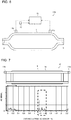
- Fig. 1 is a schematic configuration diagram illustrating a life estimation apparatus 100 for a pressure accumulator 10, according to an embodiment of the present disclosure.
- the life estimation apparatus 100 includes a pressure accumulator 10, two AE sensors 11a and 11b, a non-destructive sensor 12 and an estimation unit 13.
- the life estimation apparatus 100 estimates the life of the pressure accumulator 10, based on AE signals for the pressure accumulator 10.
- the pressure accumulator 10 includes a container 1 that is made of metal and that has opened portions, and lid members 2 that are provided at the opened portions of the container 1 to close the opened portions.
- the container 1 is a metallic cylinder member 1a having the opening portions at both end portions of the metallic cylinder member 1a, and the lid members 2 close the respective opened portions at the both end portions of the metallic cylinder member 1a.
- sealing members 3 On inner sides of the lid members 2 in the container 1, sealing members 3 that seal the inside of the container 1 are provided.
- a carbon-fiber reinforced resin member 4 is provided to cover an outer circumferential portion of the metallic cylinder member 1a.
- the carbon-fiber reinforced resin member 4 is provided to secure a mechanical strength of the pressure accumulator 10 that is a required pressure resistance, and is wound in such a manner as to cover a storage member at an outer circumference surface of the metallic cylinder member 1a.
- the metallic cylinder member 1a is made of a low-alloy steel, for example. That is, the metallic cylinder member 1a is made of a material containing any one of chrome-molybdenum steel, nickel-chrome-molybdenum steel, manganese-chrome steel, manganese steel and boron-containing steel, for example.
- the carbon-fiber reinforced resin member 4 is a layer for ensuring the mechanical strength of the pressure accumulator 10 that is a required pressure resistance, and is wound in such a manner as to cover the storage member on the outer circumference surface of the metallic cylinder member 1a.
- the carbon-fiber reinforced resin member 4 is a composite material in which a carbon fiber is used as a reinforcement and is impregnated with a resin to enhance the strength, and for example, a PAN based carbon fiber or a PITCH based carbon fiber is used.
- the PAN based carbon fiber is used for various purposes, for example, for aircraft, and is widely spread.
- the PITCH based carbon fiber has a lower strength than that of the PAN based carbon fiber, but has a higher elastic modulus and thus a higher stiffness than those of the PAN based carbon fiber.
- the Young's modulus of the PITCH based carbon fiber is 620 GPa or 780 GPa, whereas the Young's modulus of the PAN based carbon fiber is 230 GPa.
- the PITCH based carbon fiber has a high elastic modulus and thus has a high stiffness, as compared with the PAN based carbon fiber.
- the tensile strength TS of the PITCH based carbon fiber is 3600 GPa, whereas the tensile strength TS of the PAN based carbon fiber is 5000 GPa.
- the PAN based carbon fiber has a higher strength than that of the PITCH based carbon fiber.
- the lid members 2 are attached to the end portions of the metallic cylinder member 1a, and are used to close the metallic cylinder member 1a.
- a valve not illustrated is provided, and is used to enclose or release a substance in or from the metallic cylinder member.
- a through-hole or through-holes are formed for connection of the valve or valves.
- the two AE sensors 11a and 11b are provided at the pressure accumulator 10, and each detect an AE signal.
- the number of the AE sensors 11a and 11b to be provided is one or more, and preferably, should be two or more. In the case where two or more AE sensors 11a and 11b are provided, it is possible to locate a fatigue damage part of the pressure accumulator 10 based on a relative difference between AE signals detected by the two or more AE sensors 11a and 11b.
- the two AE sensors 11a and 11b are provided at the both end portions of the container 1. It should be noted that one or more AE sensors 11a and 11b may be provided at the container 1 and/or the lid member or members 2.
- the AE sensors 11a and 11b are set on a surface of a target material, and each detect an AE wave generated by formation of a crack in the material, as an AE signal. It should be noted that the AE sensors 11a and 11b may be set at the pressure accumulator 10 only at the time at which a safety inspection is made; that is, it is not indispensable that the AE sensors 11a and 11b are set at all times at the pressure accumulator 10.
- the two AE sensors 11a and 11b are each used to detect a damage AE signal that is generated from the pressure accumulator 10 because of damage of the material during use of the pressure accumulator 10. It should be noted that the damage AE signal generated because of the above damage includes an AE signal generated because of a fatigue damage.
- the non-destructive sensor 12 detects a fatigue crack depth that is the depth of a fatigue crack, according to a non-destructive inspection method.
- a non-destructive inspection method for use in the non-destructive sensor 12 for example, an ultrasonic testing, a magnetic particle testing or an eddy current testing is used. Of these methods, preferably, the eddy current testing, which enables a crack having a size of 0.1 mm or more to be detected, should be used. Therefore, the non-destructive sensor 12 detects the fatigue crack depth according to the eddy current testing.
- the non-destructive sensor 12 may be set at the pressure accumulator 10 only in the case where the AE sensors 11a and 11b each detect an AE signal indicating that a crack is formed in the material; that is, it is not indispensable that the non-destructive sensor 12 is set at all times at the pressure accumulator 10.
- Fig. 2 is a block diagram illustrating the estimation unit 13 according to the embodiment of the present disclosure.
- the estimation unit 13 is a processing circuit provided with a microcomputer that includes a CPU, a memory such as a ROM and a RAM, and an input/output device such as an I/O port.
- the estimation unit 13 receives signals from the two AE sensors 11a and 11b and the non-destructive sensor 12, wirelessly or through a communication wire.
- the estimation unit 13 may be set at the pressure accumulator 10 only at the time at which the safety inspection is performed; that is, it is not indispensable that the estimation unit 13 is set at all times at the pressure accumulator 10.
- the estimation unit 13 determines the time point at which the AE signals are detected as a minimum initial flaw generation time point that is the time point at which a minimum initial flaw at the pressure accumulator 10 is generated in shipping the pressure accumulator 10, the detection of generation of the minimum initial flaw being detected by the non-destructive inspection method.
- the non-destructive inspection method for use in detection of generation of the minimum initial flaw at the pressure accumulator 10 in the shipping of the pressure accumulator 10 for example, an ultrasonic testing, a magnetic particle testing or an eddy current testing is used.
- the magnetic particle testing which enables a 0.3 mm crack to be detected, should be used. Therefore, the magnetic particle testing is used in detection of generation of the minimum initial flaw at the pressure accumulator 10 in the shipping of the pressure accumulator 10, and 0.3 mm is set as the size of the minimum initial flaw.
- the AE sensors 11a and 11b are set at all times at the pressure accumulator 10, first damage AE signals can be immediately detected for the estimation unit 13.
- the frequency of the safety inspection is set such that first damage AE signals can be detected for the estimation unit 13 when the size of the crack is smaller than or equal to 0.3 mm, which is the size of the minimum initial flaw that can be detected in the magnetic particle testing.
- the estimation unit 13 specifies a fatigue damage part of the pressure accumulator 10 based on a relative difference between damage AE signals generated as a result of detection by the two AE sensors 11a and 11b.
- the estimation unit 13 may detect a fatigue crack depth that is the depth of a fatigue crack part of the pressure accumulator 10 at the minimum initial flaw generation time point, from the damage AE signal. Furthermore, the estimation unit 13 may determine that a flaw crack whose size corresponds to the values of the damage AE signals that correspond to a fatigue damage degree is generated, and may estimate an allowable fatigue life of the pressure accumulator 10 from the above flaw crack.
- Fig. 3 is a flowchart indicating an estimation method of the life estimation apparatus 100 for the pressure accumulator 10 according to the embodiment of the present disclosure.
- the processing according to the estimation method may be applied only at the time when the safety inspection is performed; that is, it is not indispensable that the processing according to the estimation method is applied at all time.
- step S11 the two AE sensors 11a and 11b detect damage AE signals from the pressure accumulator 10, and the estimation unit 13 determines whether the damage AE signals are detected or not.
- step S11 the step to be carried out proceeds to step S12.
- step S11 the AE signals are not detected, the processing ends.
- the detection of the damage AE signals from the pressure accumulator 10 by the two AE sensors 11a and 11b at least at a safety inspection frequency at which first damage AE signals can be detected when the size of a crack is smaller than or equal to at least 0.3 mm, which is the size of the minimum initial flaw that can be detected by the magnetic particle testing.
- step S12 when the AE sensors 11a and 11b detect damage AE signals that are generated from the pressure accumulator 10 because of damage of the material, the estimation unit 13 sets the time point at which the AE signals are detected, as the minimum initial flaw generation time point that is the time point at which the minimum initial flaw of the pressure accumulator 10 that is detected by the magnetic particle testing is generated in the shipping of the pressure accumulator 10. In this case, since the two AE sensors 11a and 11b are provided, the estimation unit 13 locates a fatigue damage part of the pressure accumulator 10 based on the relative difference between the damage AE signals detected by the two AE sensors 11a and 11b. After the process of step S12, the processing proceeds to step S13.
- Fig. 4 is an explanatory diagram illustrating a correlation between the AE signals detected by the AE sensors 11a and 11b and an estimation characteristic for the life of the pressure accumulator 10 according to the embodiment of the present disclosure.
- the estimation unit 13 sets the time point at which the AE signals are detected, as the minimum initial flaw generation time point, that is, the time point at which a minimum initial flaw having a size of 0. 3mm which is detected by the magnetic particle testing is generated in the shipping of the pressure accumulator 10, whose fatigue characteristic is indicated by a dotted line.
- the estimation unit 13 temporarily estimates an allowable fatigue life of the pressure accumulator 10 from the crack having a size of 0.3 mm, as an estimation characteristic that is indicated by a solid line.
- the estimation characteristic for the life that is obtained from the minimum initial flaw whose size is 0.3 mm is previously investigated.
- the estimation characteristic is determined as a temporary estimation characteristic, and the allowable fatigue life of the pressure accumulator 10 is estimated.
- the allowable fatigue life of the pressure accumulator 10 may be definitely set based on the estimation characteristic.
- the estimation characteristic further approaches an actual life characteristic of an actual life, which is indicated by a dash-dot-dash line in the figure. Then, it is possible to estimate an allowable fatigue life closer to the actual life.
- step S13 the non-destructive sensor 12, according to the eddy current testing, detects the fatigue crack depth that is the depth of the fatigue damage part pf the pressure accumulator 10 at the minimum initial flaw generation time point, and the estimation unit 13 determines whether the fatigue crack depth is detected. In the case where in step S13, the fatigue crack depth is detected, the processing proceeds to step S14. In the case where in step S13, the fatigue crack depth is not detected, the processing proceeds to step S15.
- v the AE sensors 11a and 11b may detect, from the damage AE signals, the fatigue crack depth of the fatigue damage part of the pressure accumulator 10 at the minimum initial flaw generation time point.
- step S14 the estimation unit 13 determines that the fatigue crack detected by the non-destructive sensor 12 according to the eddy current testing is generated, and estimates the allowable fatigue life of the pressure accumulator 10 from the fatigue crack.
- the size of the minimum flaw crack that is detected by the non-destructive sensor 12 according to the eddy current testing is 0.1 mm. Therefore, the fatigue crack to be detected in step S14 has a depth of 0.1 mm or more. Thus, it is determined as a prediction that a fatigue damage will be generated based on a previously investigated fatigue damage characteristic obtained from the fatigue crack detected by the non-destructive sensor 12, and the life of the pressure accumulator 10 is estimated.
- the fatigue damage characteristic may be estimated based on the comparison between the minimum flaw characteristic from the minimum flaw crack having a size of 0.1 mm that is detected by the eddy current testing and the estimation characteristic from the initial flaw having a size of 0.3 mm that is detected by the magnetic particle testing in step S12.
- Step S14 may be carried out in the case where for the estimation unit 13, the AE sensors 11a and 11b detects from the damage AE signals, the fatigue crack depth of the fatigue damage part of the pressure accumulator 10 at the minimum initial flaw generation time point.
- the estimation unit 13 determines that a flaw crack whose size corresponds to the values of the AE signals detected by the AE sensors 11a and 11b that correspond to the fatigue damage degree is generated. Then, the estimation unit 13 estimates the allowable fatigue life of the pressure accumulator 10 from the above flaw crack.
- the fatigue damage characteristic that is referred to in the estimation of the allowable fatigue life of the pressure accumulator 10 may be obtained in the same manner as in step S14.
- the processing may end. It should be noted that the processing may proceed to step S16.
- step S15 the estimation unit 13 determines that a crack having a size of 0.1 mm, which is the size of the minimum flaw crack that is detected at the minimum initial flaw generation time point by the non-destructive sensor 12 according to the eddy current testing is generated.
- the estimation unit 13 estimates the allowable fatigue life of the pressure accumulator 10 based on the minimum flaw characteristic from the minimum flaw crack.
- step S15 the processing may end. It should be noted that the processing may proceed to step S16.
- Fig. 5 is an explanatory diagram illustrating a correlation between AE signals detected by the AE sensors 11a and 11b and the minimum flaw characteristic for the life of the pressure accumulator 10, according to the eddy current testing in the embodiment of the present disclosure.
- the estimation unit 13 determines the point of time at which first damage AE signals are detected, as the point of time at which a crack having a size of 0.1 mm which is the minimum flaw crack that can be detected by the non-destructive sensor 12 according to the eddy current testing is generated.
- the estimation unit 13 estimates the allowable fatigue life of the pressure accumulator 10 from the minimum flaw crack having a size of 0.1 mm, from the temporal estimation characteristic that is indicated by a broken line, as a minimum flaw characteristic obtained using the non-destructive sensor 12 according to the eddy current testing, the minimum flaw characteristic being indicated by a solid line in the figure.
- the minimum flaw characteristic obtained using the non-destructive sensor 12 according to the eddy current testing is previously investigated. As a result, the minimum flaw characteristic further approaches the actual life characteristic indicated by a dash-dot-dash line in the figure, than the estimation characteristic. Then, it is possible to estimate an allowable fatigue life that is further close to the actual life.
- step S16 when the AE sensors 11a and 11b detect damage AE signals, a worker removes a fatigue damage part, for example, by polishing, to extend the life of the pressure accumulator 10.
- the fatigue damage part is located from the difference between the damage AE signals detected by the AE sensors 11a and 11b. Therefore, since the depth of the fatigue crack at the time when first damage AE signals are detected is considered smaller than or equal to 0.3 mm, which is the size of the minimum crack depth according to the magnetic particle testing, a fatigue crack itself on an inner surface side of the metallic cylinder member 1a is removed. Therefore, the fatigue damage part is removed, and the life of the pressure accumulator 10 can be further extended.
- the processing ends.
- Fig. 6 is a schematic configuration diagram illustrating a life estimation apparatus 100 for a pressure accumulator 10, according to a modification of the embodiment of the present disclosure.
- the configurations of components other than the pressure accumulator 10 are the same as the configurations described above regarding the above embodiment, and their descriptions will thus be omitted.
- the following description is made concerning configurations of the pressure accumulator 10 that are not described above.
- Fig. 6 illustrates an example of the container 1 in which the both end sides of the container 1 are smaller in diameter than the body.
- the end sides of the container 1 are small in diameter and formed hemispherically, forming shoulder portions of a tank type container.
- Lid members 2 are provided at opened portions of the both end portions of the container 1. Since the container 1 is a tank type container, the two AE sensors 11a and 11b are provided at the container 1.
- Fig. 7 is an explanatory diagram illustrating a location result based on the AE signals from two AE sensors 11a and 11b in an example of the embodiment of the present disclosure.
- the inventors performed a position location based on AE signals detected by the two AE sensors 11a and 11b, using the life estimation apparatus 100 for the pressure accumulator 10 according to the embodiment, and as illustrated in Fig. 7 , a damage part which causes a damage AE signal to be generated and whose fatigue crack depth is very shallow could be detected.
- the location result as indicated in Fig. 7 was obtained by the process of step S11 in the flowchart of Fig. 3 .
- the point of time at which the damage AE signal was detected was set as the initial flaw generation time point by the process of step S12 in the flowchart of Fig. 3 , and the fatigue crack depth was detected by the non-destructive sensor 12 according to the eddy current testing in the process of step S13.
- the damage part was detected as a flaw that has a size of 0.1 mm from the inner surface of the container 1 of the pressure accumulator 10, in the vicinity of the center in the longitudinal direction of the container 1, by the non-destructive sensor 12 according to the eddy current testing (ET).
- the total length of the container 1 was 2.2 m.
- the damage part appeared in a range indicated by a broken line in Fig.
- the damage part could not be detected from the inner surface or outer surface of the container 1 by ultrasonic testing (UT) and penetrant testing (PT) that have been used in the past.
- UT ultrasonic testing
- PT penetrant testing
- Fig. 8 is an explanatory diagram illustrating the result of estimation of the allowable life in the example of the embodiment of the present disclosure.
- the allowable life from the fatigue crack depth could be estimated in the process of step S14.
- this flaw was set as the initial flaw, and it was analyzed how much the flaw grows due to cyclic fatigue.
- the analysis method complies with KHKS 0220 (2016) standard regarding ultra-high pressure gas facilities that is set by the High Pressure Gas Safety Institute of Japan.
- the number of repetitions that is the number of times the internal pressure was raised in order that the flaw grow to penetrate the container 1 having a thickness of 50 mm was approximately 2.5 million.
- An allowable cycle life defined as a life for which a safety factor is considered is estimated to be half of a cycle life in which the depth of the flaw reaches a value obtained by multiplying the thickness of the container 1 by 0.8.
- the allowable number of repetitions is approximately 1.2 million, which is half of a cycle number of approximately 2.5 million that is the number of repetitions required until the depth of the crack reaches 40 mm that is a value obtained by multiplying 50 mm that is the thickness of the container 1, by 0.8 that is the safety factor.
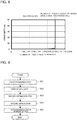
- Fig. 9 is a flowchart indicating the manufacturing method of the pressure accumulator 10 according to the embodiment of the present disclosure. As indicated in Fig. 9 , the manufacturing method of the pressure accumulator 10 includes a first estimation step S21, a first design step S22, a second estimation step S23, a second design step S24, and a decarburized-layer removal step S25.
- the AE sensors 11a and 11b provided at the pressure accumulator 10 estimate the range of stress levels at each of which a damage AE signal that is generated from the pressure accumulator 10 because of the damage of the material of the pressure accumulator 10 is in a predetermined state in which a damage AE signal is prominently generated.
- Fig. 10 is a diagram indicating a correlation between the elastic deformation and plastic deformation of metal and the state of generation of a damage AE signal in the embodiment of the present disclosure.
- Fig. 11 is an explanatory diagram indicating a stress level range in the first estimation step S21 in the embodiment of the present disclosure.
- the graph of Fig. 10 indicates the state of generation of a damage AE signal in a tensile test conducted only once.
- a damage AE signal is prominently generated in a process in which the state of the metal changes from elastic deformation to plastic deformation as indicated in Fig. 10 , and from conventional knowledge, it can be seen that generation of a damage AE signal does not prominently occur in an elastic deformation range in which the state of metal is elastic deformation.
- the inventors paid attention to a fatigue failure in which that a failure occurs at the elastic deformation range, and clarified that an AE signal is generated when damage occurs because of fatigue, even in the elastic deformation range, when the stress level is in a specific stress range.
- the characteristic of the metal as indicated in Fig. 8 is previously investigated, and a range between an upper limit and lower limit of a fatigue critical stress is estimated.
- the AE sensors 11a and 11b provided at the pressure accumulator 10 estimate that the stress level at which a damage AE signal that is generated from the pressure accumulator 10 because of the damage of the material is in the predetermined state in which an AE signal is prominently generated falls within the range between stress levels that are 0.25 times to 1.50 times higher than the level of the fatigue limit stress.
- the pressure accumulator 10 is designed such that the minimum thickness of the pressure accumulator 10 is determined based on the stress level estimated in the first estimation step S21. Therefore, the minimum thickness is determined such that the stress level at which a damage AE signal that is generated from the pressure accumulator 10 because of the damage of the material is in the predetermined state in which a damage AE signal is prominently generated can be applied to the minimum thickness.
- the pressure accumulator 10 is sealed, with hydrogen enclosed in the pressure accumulator 10. In view of this point, a fatigue limit until which hydrogen degradation in the fatigue characteristic does not become apparent is estimated based on the influence of hydrogen on the fatigue characteristic of the material of the pressure accumulator 10.
- Fig. 12 is an explanatory diagram indicating a stress level range after the first estimation step S21 and the second estimation step S23 in the embodiment of the present disclosure. As illustrated in Fig. 12 , in consideration of the fatigue limit until which the hydrogen degradation in the fatigue characteristic does not become apparent, the range estimated in the first estimation step S21 is further limited, and a hatched range as indicated in the figure is estimated.
- the pressure accumulator 10 is designed such that the minimum thickness is determined based on a stress level that is lower than or equal to the fatigue limit estimated in the second estimation step S23. As a result, the determined minimum thickness is suitable for the case where hydrogen is enclosed in the pressure accumulator 10.
- Fig. 13 is an explanatory diagram indicating stress characteristics depending on whether or not honing processing is performed on the inner surface of the container 1 according to the embodiment of the present disclosure.
- Fig. 14 is an explanatory diagram indicating stress characteristics depending on whether or not machine processing is performed on the inner surface of the entire container 1 or whether or not the machine processing is performed on the inner surface of only the metallic cylinder member 1a according to the embodiment of the present disclosure.
- the decarburized layer on the material of the pressure accumulator 10 is removed, and the stress tolerability is improved. As a result, the life of the pressure accumulator 10 can be extended.
- the pressure accumulator 10 is produced while using AE signals for the pressure accumulator 10.
- the manufacturing method of the pressure accumulator 10 includes the first estimation step S21 in which the AE sensors 11a and 11b provided at the pressure accumulator 10 estimate the range of the stress levels at each of which a damage AE signal that is generated from the pressure accumulator 10 because of the damage of the material of the pressure accumulator 10 is in the predetermined state.
- the manufacturing method of the pressure accumulator 10 includes the first design step S22 of designing the pressure accumulator 10 such that the minimum thickness is determined based on the stress level estimated in the first estimation step S21.
- the AE sensors 11a and 11b detect damage AE signals from the pressure accumulator 10, whose signal degrees are each the prominent signal degree in which the AE signals are in the predetermined state. Therefore, even in the pressure accumulator 10 whose life is determined as a diagnosis, for example, only by annual safety inspection, the AE signal can be reliably detected without fail, in the safety inspection.
- the AE sensors 11a and 11b provided at the pressure accumulator 10 estimate that the stress level at which a damage AE signal that is generated from the pressure accumulator 10 because of the damage of the material is in the predetermined state falls within the range of stress levels that are 0.25 times to 1.50 times higher than the level of the fatigue limit stress.
- the AE sensors 11a and 11b detect, from the pressure accumulator 10, damage AE signals whose signal degrees are each the prominent signal degree in which the stress level is in the range of stress levels that are 0.25 times to 1.50 times higher than the level of the fatigue limit stress, so that the damage AE signals are in the predetermined state.
- the stress level is lower than the level that is 0.25 times higher than the level of the fatigue limit stress, the amount of the damage AE signal generated because of the damage of the material is small.
- the stress level is higher than the level that is 1.50 times higher than the level of the fatigue limit stress, a damage AE signal that is generated because of the plastic deformation of the material cannot be detected.
- the manufacturing method of the pressure accumulator 10 includes the second estimation step S23 of estimating the fatigue limit until which the hydrogen degradation in the fatigue characteristic does not become apparent, based on the influence of hydrogen on the fatigue characteristic of the material of the pressure accumulator 10.
- the manufacturing method of the pressure accumulator 10 includes the second design step S24 of designing the pressure accumulator 10 such that the minimum thickness of the pressure accumulator 10 is determined based on a stress level that is lower than or equal to the fatigue limit estimated in the second estimation step S23.
- the pressure accumulator 10 when the pressure accumulator 10 is damaged due to fatigue and is in use, the AE sensors 11a and 11b detect AE signals from the pressure accumulator 10 that are in a state in which the stress level is lower than or equal to the fatigue limit until which the hydrogen degradation is not made apparent by the influence of the hydrogen enclosed in the pressure accumulator 10. Therefore, the pressure accumulator 10 is designed suitable for hydrogen enclosed in the pressure accumulator 10.
- the manufacturing method of the pressure accumulator 10 includes the decarburized-layer removal step S25 of removing the decarburized layer on at least the inner surface of the surfaces of the base material of the pressure accumulator 10, that is, of the inner surface and outer surface of the base material.
- the decarburized layer is removed from the base material of the pressure accumulator 10, and the stress tolerability of the pressure accumulator 10 can be improved. Furthermore, when the pressure accumulator 10 is damaged due to fatigue and is in use, the AE sensors 11a and 11b can more accurately detect damage AE signals from the pressure accumulator 10, whose signal degrees are each the prominent signal degree in which the AE signals are in the predetermined state.
- the pressure accumulator 10 includes the AE sensors 11a and 11b that are provided at the pressure accumulator 10 and detect AE signals.
- the AE sensors 11a and 11b can detect AE signals from the pressure accumulator 10, whose signal degrees are each the prominent signal degree in which the AE signals are in the predetermined state.
- the pressure accumulator 10 includes the container 1 that is made of metal and has opened portions.
- the pressure accumulator 10 includes the lid members 2 that are provided at the opened portions of the container 1 to close the opened portions.
- the AE sensors 11a and 11b can detect AE signals from the container 1, whose signal degrees are each the prominent signal degree in which the AE signals are in the predetermined state.
- the AE sensors 11a and 11b are provided at one or both of the container 1 and the lid members 2.
- the AE sensors 11a and 11b can detect AE signals from the container 1.
- the container 1 is the metallic cylinder member 1a.
- the opening portions of the both end portions of the metallic cylinder member 1a are closed by the lid members 2.
- the AE sensors 11a and 11b can detect AE signals from the metallic cylinder member 1a.
- the pressure accumulator 10 includes the carbon-fiber reinforced resin member 4 that covers the outer circumferential portion of the metallic cylinder member 1a.
- the carbon-fiber reinforced resin member 4 covers the outer circumferential portion of the metallic cylinder member 1a, the durability of the metallic cylinder member 1a can be improved.
Landscapes
- Engineering & Computer Science (AREA)
- General Engineering & Computer Science (AREA)
- Mechanical Engineering (AREA)
- Physics & Mathematics (AREA)
- General Physics & Mathematics (AREA)
- Analytical Chemistry (AREA)
- Life Sciences & Earth Sciences (AREA)
- Chemical & Material Sciences (AREA)
- Health & Medical Sciences (AREA)
- Biochemistry (AREA)
- General Health & Medical Sciences (AREA)
- Acoustics & Sound (AREA)
- Immunology (AREA)
- Pathology (AREA)
- Aviation & Aerospace Engineering (AREA)
- Investigating Or Analyzing Materials By The Use Of Ultrasonic Waves (AREA)
- Filling Or Discharging Of Gas Storage Vessels (AREA)
- Supply Devices, Intensifiers, Converters, And Telemotors (AREA)
Abstract
Description
- The present disclosure relates to a manufacturing method of a pressure accumulator that is sealed, with a high-pressure gas, such as hydrogen, or another kind of gas, enclosed in the pressure accumulator, and a life extension method for the pressure accumulator.
- In an existing technique, a diagnosis is made using acoustic emission (hereinafter referred to as AE) to determine the life of a bearing provided in a rotary machine (see
Patent Literature 1, for example). In the technique disclosed inPatent Literature 1, a reference maximum amplitude value of an AE signal and a maximum amplitude value of an AE signal for a bearing that is in use are compared with each other, to thereby estimate the life of the bearing as the result of a diagnosis. - Patent Literature 1: Japanese Unexamined Patent Application Publication No.
2012-242336 - The estimation of a life based on an AE signal can also be applied to a pressure accumulator that is sealed, with a high-pressure gas such as hydrogen, for example, enclosed in the pressure accumulator. It should be noted that in the technique disclosed in
Patent Literature 1, the maximum amplitude value of the AE signal is periodically acquired, and the life of the bearing is estimated by a diagnosis. A repetitive lifetime diagnosis is unsuitable for a pressure accumulator whose life is estimated, for example, only by annual safety inspection. Furthermore, for the pressure accumulator whose lift is estimated, for example, only by annual safety inspection, the safety inspection is required to reliably detect an AE signal without fail. - The present disclosure is applied to solve the above problem, and relates to a manufacturing method of a pressure accumulator, which enables an AC signal to be reliably detected without fail.
-
- [1] A manufacturing method for manufacturing a pressure accumulator, using an AE signal for the pressure accumulator, the manufacturing method includes:
- a first estimation step of estimating with an AE sensor provided at the pressure accumulator, a range of stress levels at each of which a damage AE signal that is generated from the pressure accumulator because of damage of material of the pressure accumulator is in a predetermined state; and
- a first design step of designing the pressure accumulator such that a minimum thickness of the pressure accumulator is determined based on the stress level range estimated in the first estimation step.
- [2] In the manufacturing method of the above item [1], in the first estimation step, the AE sensor provided at the pressure accumulator estimates that the range of the stress levels at each of which the damage AE signal generated from the pressure accumulator because of the damage of the material is in the predetermined state is a range between stress levels that are 0.25 times to 1.50 times higher than the level of a fatigue limit stress.
- [3] The manufacturing method of the above item [1] or [2] further includes:
- a second estimation step of estimating a fatigue limit until which hydrogen degradation in the fatigue characteristic does not become apparent, based on influence of hydrogen on a fatigue characteristic of the material of the pressure accumulator; and
- a second design step of designing the pressure accumulator such that the minimum thickness of the pressure accumulator is determined based on a stress level that is lower than or equal to the fatigue limit estimated in the second estimation step.
- [4] The manufacturing method of any one of the above items [1] to [3] further includes a removal step of removing a decarburized layer on at least an inner surface of the inner surface and an outer surface of a base material of the pressure accumulator.
- [5] In the manufacturing method of any one of the above items [1] to [4], the pressure accumulator includes an AE sensor provided at the pressure accumulator to detect the AE signal.
- [6] In the manufacturing method of any one of the above items [1] to [5], the pressure accumulator includes:
- a container made of metal and having an opened portion; and
- a lid member provided at the opened portion of the container to close the opened portion.
- [7] In the manufacturing method of the above item [6], the AE sensor is provided at one or both of the container and the lid member.
- [8] In the manufacturing method of the above item [6] or [7], the container is a metallic cylinder member having both end portions that are opened, and the lid member closes the opened portions of the both end portions of the metallic cylinder member.
- [9] In the manufacturing method of the above item [8], the pressure accumulator includes a carbon-fiber reinforced resin member that covers an outer circumferential portion of the metallic cylinder member.
- According to the manufacturing method of the pressure accumulator of the embodiment of the present disclosure, the AE sensor provided at the pressure accumulator estimates the range of the stress levels at each of which the AE signal that is generated from the pressure accumulator because of the damage of the material of the pressure accumulator is in the predetermined state, and the pressure accumulator is designed such that the minimum thickness is determined based on the estimated stress level range. Thus, when the pressure accumulator is damaged due to fatigue and is in use, the AE sensor detects an AE signal from the pressure accumulator whose signal degree is a prominent signal degree in which the AE signal is in the predetermined state. Therefore, even in a pressure accumulator whose life is determined as a diagnosis, for example, only by annual safety inspection, an AE signal can be reliably detected without fail, in the safety inspection.
-
- [
Fig. 1] Fig. 1 is a schematic configuration diagram illustrating a life estimation apparatus for a pressure accumulator, according to an embodiment of the present disclosure. - [
Fig. 2] Fig. 2 is a block diagram illustrating an estimation unit according to the embodiment of the present disclosure. - [
Fig. 3] Fig. 3 is a flowchart of an estimation method for the life estimation apparatus for the pressure accumulator according to the embodiment of the present disclosure. - [
Fig. 4] Fig. 4 is an explanatory diagram illustrating a correlation between AE signals detected by AE sensors and an estimation characteristic for the life of the pressure accumulator according to the embodiment of the present disclosure. - [
Fig. 5] Fig. 5 is an explanatory diagram illustrating a correlation between the AE signals detected by the AE sensors and a minimum flaw characteristic for the life of the pressure accumulator based on an eddy current testing, according to the embodiment of the present disclosure. - [
Fig. 6] Fig. 6 is a schematic configuration diagram illustrating a life estimation apparatus for a pressure accumulator, in a modification of the embodiment of the present disclosure. - [
Fig. 7] Fig. 7 is an explanatory diagram indicating a location result based on AE signals detected by AE sensors in an example of the embodiment of the present disclosure. - [
Fig. 8] Fig. 8 is an explanatory diagram illustrating the result of estimation of an allowable life in the example of the embodiment of the present disclosure. - [
Fig. 9] Fig. 9 is a flowchart indicating a manufacturing method of the pressure accumulator according to the embodiment of the present disclosure. - [
Fig. 10] Fig. 10 is a diagram indicating a correlation between the elastic deformation and plastic deformation of metal and the state of generation of a damage AE signal in the embodiment of the present disclosure. - [
Fig. 11] Fig. 11 is an explanatory diagram indicating a stress level range in a first estimation step in the embodiment of the present disclosure. - [
Fig. 12] Fig. 12 is an explanatory diagram indicating a stress level range after the first estimation step and a second estimation step in the embodiment of the present disclosure. - [
Fig. 13] Fig. 13 is an explanatory diagram indicating stress characteristics depending on whether or not honing processing is performed on an inner surface of a container according to the embodiment of the present disclosure. - [
Fig. 14] Fig. 14 is an explanatory diagram indicating stress characteristics depending on whether or not machine processing is performed on an inner surface of the entire container is performed or whether or not machine processing is performed on an inner surface of only a metallic cylinder member according to the embodiment of the present disclosure. - A pressure accumulator according to a preferred embodiment of the present disclosure will be described below in detail with reference to the drawings. The embodiment will be descried below as a preferred specific example of the pressure accumulator. Therefore, the following description includes various limitations concerning technically preferred configurations. However, the scope of the present disclosure is not limited to such configurations unless the present disclosure contains a description to the effect that a configuration is limited as described in the present disclosure.
-
Fig. 1 is a schematic configuration diagram illustrating alife estimation apparatus 100 for apressure accumulator 10, according to an embodiment of the present disclosure. As illustrated inFig. 1 , thelife estimation apparatus 100 includes apressure accumulator 10, twoAE sensors non-destructive sensor 12 and anestimation unit 13. Thelife estimation apparatus 100 estimates the life of thepressure accumulator 10, based on AE signals for thepressure accumulator 10. - In the
pressure accumulator 10, hydrogen is stored, for example, in a hydrogen station. Thepressure accumulator 10 includes acontainer 1 that is made of metal and that has opened portions, andlid members 2 that are provided at the opened portions of thecontainer 1 to close the opened portions. To be more specific, thecontainer 1 is ametallic cylinder member 1a having the opening portions at both end portions of themetallic cylinder member 1a, and thelid members 2 close the respective opened portions at the both end portions of themetallic cylinder member 1a. On inner sides of thelid members 2 in thecontainer 1, sealingmembers 3 that seal the inside of thecontainer 1 are provided. In thecontainer 1, a carbon-fiber reinforcedresin member 4 is provided to cover an outer circumferential portion of themetallic cylinder member 1a. The carbon-fiber reinforcedresin member 4 is provided to secure a mechanical strength of thepressure accumulator 10 that is a required pressure resistance, and is wound in such a manner as to cover a storage member at an outer circumference surface of themetallic cylinder member 1a. - The
metallic cylinder member 1a is made of a low-alloy steel, for example. That is, themetallic cylinder member 1a is made of a material containing any one of chrome-molybdenum steel, nickel-chrome-molybdenum steel, manganese-chrome steel, manganese steel and boron-containing steel, for example. - The carbon-fiber reinforced
resin member 4 is a layer for ensuring the mechanical strength of thepressure accumulator 10 that is a required pressure resistance, and is wound in such a manner as to cover the storage member on the outer circumference surface of themetallic cylinder member 1a. The carbon-fiber reinforcedresin member 4 is a composite material in which a carbon fiber is used as a reinforcement and is impregnated with a resin to enhance the strength, and for example, a PAN based carbon fiber or a PITCH based carbon fiber is used. - The PAN based carbon fiber is used for various purposes, for example, for aircraft, and is widely spread. The PITCH based carbon fiber has a lower strength than that of the PAN based carbon fiber, but has a higher elastic modulus and thus a higher stiffness than those of the PAN based carbon fiber. For example, the Young's modulus of the PITCH based carbon fiber is 620 GPa or 780 GPa, whereas the Young's modulus of the PAN based carbon fiber is 230 GPa. Thus, the PITCH based carbon fiber has a high elastic modulus and thus has a high stiffness, as compared with the PAN based carbon fiber. By contrast, the tensile strength TS of the PITCH based carbon fiber is 3600 GPa, whereas the tensile strength TS of the PAN based carbon fiber is 5000 GPa. Thus, the PAN based carbon fiber has a higher strength than that of the PITCH based carbon fiber.
- The
lid members 2 are attached to the end portions of themetallic cylinder member 1a, and are used to close themetallic cylinder member 1a. In at least one of thelid members 2, a valve not illustrated is provided, and is used to enclose or release a substance in or from the metallic cylinder member. In thelid member 2 or thelid members 2, a through-hole or through-holes are formed for connection of the valve or valves. - The two
AE sensors pressure accumulator 10, and each detect an AE signal. The number of theAE sensors more AE sensors pressure accumulator 10 based on a relative difference between AE signals detected by the two ormore AE sensors AE sensors container 1. It should be noted that one ormore AE sensors container 1 and/or the lid member ormembers 2. TheAE sensors AE sensors pressure accumulator 10 only at the time at which a safety inspection is made; that is, it is not indispensable that theAE sensors pressure accumulator 10. The twoAE sensors pressure accumulator 10 because of damage of the material during use of thepressure accumulator 10. It should be noted that the damage AE signal generated because of the above damage includes an AE signal generated because of a fatigue damage. - The
non-destructive sensor 12 detects a fatigue crack depth that is the depth of a fatigue crack, according to a non-destructive inspection method. As the non-destructive inspection method for use in thenon-destructive sensor 12, for example, an ultrasonic testing, a magnetic particle testing or an eddy current testing is used. Of these methods, preferably, the eddy current testing, which enables a crack having a size of 0.1 mm or more to be detected, should be used. Therefore, thenon-destructive sensor 12 detects the fatigue crack depth according to the eddy current testing. It should be noted that thenon-destructive sensor 12 may be set at thepressure accumulator 10 only in the case where theAE sensors non-destructive sensor 12 is set at all times at thepressure accumulator 10. -
Fig. 2 is a block diagram illustrating theestimation unit 13 according to the embodiment of the present disclosure. As illustrated inFig. 2 , theestimation unit 13 is a processing circuit provided with a microcomputer that includes a CPU, a memory such as a ROM and a RAM, and an input/output device such as an I/O port. Theestimation unit 13 receives signals from the twoAE sensors non-destructive sensor 12, wirelessly or through a communication wire. It should be noted that theestimation unit 13 may be set at thepressure accumulator 10 only at the time at which the safety inspection is performed; that is, it is not indispensable that theestimation unit 13 is set at all times at thepressure accumulator 10. - When the
AE sensors pressure accumulator 10 because of damage of the material during use of thepressure accumulator 10, theestimation unit 13 determines the time point at which the AE signals are detected as a minimum initial flaw generation time point that is the time point at which a minimum initial flaw at thepressure accumulator 10 is generated in shipping thepressure accumulator 10, the detection of generation of the minimum initial flaw being detected by the non-destructive inspection method. As the non-destructive inspection method for use in detection of generation of the minimum initial flaw at thepressure accumulator 10 in the shipping of thepressure accumulator 10, for example, an ultrasonic testing, a magnetic particle testing or an eddy current testing is used. Of these methods, preferably, the magnetic particle testing, which enables a 0.3 mm crack to be detected, should be used. Therefore, the magnetic particle testing is used in detection of generation of the minimum initial flaw at thepressure accumulator 10 in the shipping of thepressure accumulator 10, and 0.3 mm is set as the size of the minimum initial flaw. In the case where theAE sensors pressure accumulator 10, first damage AE signals can be immediately detected for theestimation unit 13. In the case where theAE sensors pressure accumulator 10 only at the time when the safety inspection is performed, the frequency of the safety inspection is set such that first damage AE signals can be detected for theestimation unit 13 when the size of the crack is smaller than or equal to 0.3 mm, which is the size of the minimum initial flaw that can be detected in the magnetic particle testing. - In addition, the
estimation unit 13 specifies a fatigue damage part of thepressure accumulator 10 based on a relative difference between damage AE signals generated as a result of detection by the twoAE sensors - Using two or
more AE sensors estimation unit 13 may detect a fatigue crack depth that is the depth of a fatigue crack part of thepressure accumulator 10 at the minimum initial flaw generation time point, from the damage AE signal. Furthermore, theestimation unit 13 may determine that a flaw crack whose size corresponds to the values of the damage AE signals that correspond to a fatigue damage degree is generated, and may estimate an allowable fatigue life of thepressure accumulator 10 from the above flaw crack. -
Fig. 3 is a flowchart indicating an estimation method of thelife estimation apparatus 100 for thepressure accumulator 10 according to the embodiment of the present disclosure. The processing according to the estimation method may be applied only at the time when the safety inspection is performed; that is, it is not indispensable that the processing according to the estimation method is applied at all time. - In step S11, the two
AE sensors pressure accumulator 10, and theestimation unit 13 determines whether the damage AE signals are detected or not. In the case where in step S11, the AE signals are detected, the step to be carried out proceeds to step S12. In the case where in step S11, the AE signals are not detected, the processing ends. It should be noted that as descried above, the detection of the damage AE signals from thepressure accumulator 10 by the twoAE sensors - In step S12, when the
AE sensors pressure accumulator 10 because of damage of the material, theestimation unit 13 sets the time point at which the AE signals are detected, as the minimum initial flaw generation time point that is the time point at which the minimum initial flaw of thepressure accumulator 10 that is detected by the magnetic particle testing is generated in the shipping of thepressure accumulator 10. In this case, since the twoAE sensors estimation unit 13 locates a fatigue damage part of thepressure accumulator 10 based on the relative difference between the damage AE signals detected by the twoAE sensors -
Fig. 4 is an explanatory diagram illustrating a correlation between the AE signals detected by theAE sensors pressure accumulator 10 according to the embodiment of the present disclosure. As illustrated inFig. 4 , when theAE sensors estimation unit 13 sets the time point at which the AE signals are detected, as the minimum initial flaw generation time point, that is, the time point at which a minimum initial flaw having a size of 0. 3mm which is detected by the magnetic particle testing is generated in the shipping of thepressure accumulator 10, whose fatigue characteristic is indicated by a dotted line. Then, theestimation unit 13 temporarily estimates an allowable fatigue life of thepressure accumulator 10 from the crack having a size of 0.3 mm, as an estimation characteristic that is indicated by a solid line. The estimation characteristic for the life that is obtained from the minimum initial flaw whose size is 0.3 mm is previously investigated. In this process, as a subsequent step is still present, the estimation characteristic is determined as a temporary estimation characteristic, and the allowable fatigue life of thepressure accumulator 10 is estimated. However, the allowable fatigue life of thepressure accumulator 10 may be definitely set based on the estimation characteristic. As a result, the estimation characteristic further approaches an actual life characteristic of an actual life, which is indicated by a dash-dot-dash line in the figure. Then, it is possible to estimate an allowable fatigue life closer to the actual life. - In step S13, the
non-destructive sensor 12, according to the eddy current testing, detects the fatigue crack depth that is the depth of the fatigue damage part pf thepressure accumulator 10 at the minimum initial flaw generation time point, and theestimation unit 13 determines whether the fatigue crack depth is detected. In the case where in step S13, the fatigue crack depth is detected, the processing proceeds to step S14. In the case where in step S13, the fatigue crack depth is not detected, the processing proceeds to step S15. - It should be noted that in step S13, v the
AE sensors pressure accumulator 10 at the minimum initial flaw generation time point. - In step S14, the
estimation unit 13 determines that the fatigue crack detected by thenon-destructive sensor 12 according to the eddy current testing is generated, and estimates the allowable fatigue life of thepressure accumulator 10 from the fatigue crack. As described later, the size of the minimum flaw crack that is detected by thenon-destructive sensor 12 according to the eddy current testing is 0.1 mm. Therefore, the fatigue crack to be detected in step S14 has a depth of 0.1 mm or more. Thus, it is determined as a prediction that a fatigue damage will be generated based on a previously investigated fatigue damage characteristic obtained from the fatigue crack detected by thenon-destructive sensor 12, and the life of thepressure accumulator 10 is estimated. - Even when the fatigue damage characteristic from the fatigue crack is not clarified, the minimum flaw crack that is detected by the
non-destructive sensor 12 according to the eddy current testing is 0.1 mm as described later, and the minimum flaw characteristic from the minimum flaw crack is previously investigated and clarified. Therefore, the fatigue damage characteristic may be estimated based on the comparison between the minimum flaw characteristic from the minimum flaw crack having a size of 0.1 mm that is detected by the eddy current testing and the estimation characteristic from the initial flaw having a size of 0.3 mm that is detected by the magnetic particle testing in step S12. - Step S14 may be carried out in the case where for the
estimation unit 13, theAE sensors pressure accumulator 10 at the minimum initial flaw generation time point. In this case, theestimation unit 13 determines that a flaw crack whose size corresponds to the values of the AE signals detected by theAE sensors estimation unit 13 estimates the allowable fatigue life of thepressure accumulator 10 from the above flaw crack. The fatigue damage characteristic that is referred to in the estimation of the allowable fatigue life of thepressure accumulator 10 may be obtained in the same manner as in step S14. After step S14, the processing may end. It should be noted that the processing may proceed to step S16. - Since in step S13, the fatigue crack depth is not detected by the
non-destructive sensor 12 according to the eddy current testing in step S13, in step S15, theestimation unit 13 determines that a crack having a size of 0.1 mm, which is the size of the minimum flaw crack that is detected at the minimum initial flaw generation time point by thenon-destructive sensor 12 according to the eddy current testing is generated. Theestimation unit 13 estimates the allowable fatigue life of thepressure accumulator 10 based on the minimum flaw characteristic from the minimum flaw crack. After step S15, the processing may end. It should be noted that the processing may proceed to step S16. -
Fig. 5 is an explanatory diagram illustrating a correlation between AE signals detected by theAE sensors pressure accumulator 10, according to the eddy current testing in the embodiment of the present disclosure. As illustrated inFig. 5 , since the fatigue crack depth is not detected by thenon-destructive sensor 12 according to the eddy current testing, theestimation unit 13 determines the point of time at which first damage AE signals are detected, as the point of time at which a crack having a size of 0.1 mm which is the minimum flaw crack that can be detected by thenon-destructive sensor 12 according to the eddy current testing is generated. Then, theestimation unit 13 estimates the allowable fatigue life of thepressure accumulator 10 from the minimum flaw crack having a size of 0.1 mm, from the temporal estimation characteristic that is indicated by a broken line, as a minimum flaw characteristic obtained using thenon-destructive sensor 12 according to the eddy current testing, the minimum flaw characteristic being indicated by a solid line in the figure. The minimum flaw characteristic obtained using thenon-destructive sensor 12 according to the eddy current testing is previously investigated. As a result, the minimum flaw characteristic further approaches the actual life characteristic indicated by a dash-dot-dash line in the figure, than the estimation characteristic. Then, it is possible to estimate an allowable fatigue life that is further close to the actual life. - In step S16, when the
AE sensors pressure accumulator 10. The fatigue damage part is located from the difference between the damage AE signals detected by theAE sensors metallic cylinder member 1a is removed. Therefore, the fatigue damage part is removed, and the life of thepressure accumulator 10 can be further extended. After step S16, the processing ends. -
Fig. 6 is a schematic configuration diagram illustrating alife estimation apparatus 100 for apressure accumulator 10, according to a modification of the embodiment of the present disclosure. The configurations of components other than thepressure accumulator 10 are the same as the configurations described above regarding the above embodiment, and their descriptions will thus be omitted. The following description is made concerning configurations of thepressure accumulator 10 that are not described above. - In the
container 1, at least one end side may be smaller in diameter than the body.Fig. 6 illustrates an example of thecontainer 1 in which the both end sides of thecontainer 1 are smaller in diameter than the body. In this example, the end sides of thecontainer 1 are small in diameter and formed hemispherically, forming shoulder portions of a tank type container.Lid members 2 are provided at opened portions of the both end portions of thecontainer 1. Since thecontainer 1 is a tank type container, the twoAE sensors container 1. -
Fig. 7 is an explanatory diagram illustrating a location result based on the AE signals from twoAE sensors AE sensors life estimation apparatus 100 for thepressure accumulator 10 according to the embodiment, and as illustrated inFig. 7 , a damage part which causes a damage AE signal to be generated and whose fatigue crack depth is very shallow could be detected. The location result as indicated inFig. 7 was obtained by the process of step S11 in the flowchart ofFig. 3 . - After the location result in
Fig. 7 was obtained, the point of time at which the damage AE signal was detected was set as the initial flaw generation time point by the process of step S12 in the flowchart ofFig. 3 , and the fatigue crack depth was detected by thenon-destructive sensor 12 according to the eddy current testing in the process of step S13. The damage part was detected as a flaw that has a size of 0.1 mm from the inner surface of thecontainer 1 of thepressure accumulator 10, in the vicinity of the center in the longitudinal direction of thecontainer 1, by thenon-destructive sensor 12 according to the eddy current testing (ET). The total length of thecontainer 1 was 2.2 m. The damage part appeared in a range indicated by a broken line inFig. 7 , and was conspicuous at a position located from theAE sensor 11b by approximately 1.2 m. The damage part could not be detected from the inner surface or outer surface of thecontainer 1 by ultrasonic testing (UT) and penetrant testing (PT) that have been used in the past. -
Fig. 8 is an explanatory diagram illustrating the result of estimation of the allowable life in the example of the embodiment of the present disclosure. As indicated inFig. 8 , the allowable life from the fatigue crack depth could be estimated in the process of step S14. To be more specific, after the 0.1 mm flaw is detected, this flaw was set as the initial flaw, and it was analyzed how much the flaw grows due to cyclic fatigue. The analysis method complies with KHKS 0220 (2016) standard regarding ultra-high pressure gas facilities that is set by the High Pressure Gas Safety Institute of Japan. As a result, the number of repetitions that is the number of times the internal pressure was raised in order that the flaw grow to penetrate thecontainer 1 having a thickness of 50 mm was approximately 2.5 million. An allowable cycle life defined as a life for which a safety factor is considered is estimated to be half of a cycle life in which the depth of the flaw reaches a value obtained by multiplying the thickness of thecontainer 1 by 0.8. To be more specific, the allowable number of repetitions is approximately 1.2 million, which is half of a cycle number of approximately 2.5 million that is the number of repetitions required until the depth of the crack reaches 40 mm that is a value obtained by multiplying 50 mm that is the thickness of thecontainer 1, by 0.8 that is the safety factor. As described above, the estimation of the allowable life from the fatigue crack depth that is made as the process of step S14 could be verified. - In order to use the
life estimation apparatus 100 for thepressure accumulator 10 as described above, it is necessary to design thepressure accumulator 10 such that theAE sensors pressure accumulator 10 is damaged due to fatigue. A manufacturing method of thepressure accumulator 10 in which thepressure accumulator 10 is manufactured by using a damage AE signal for thepressure accumulator 10 that is generated such that a damage AE signal is prominently generated when thepressure accumulator 10 is damaged due to fatigue will be described below. -
Fig. 9 is a flowchart indicating the manufacturing method of thepressure accumulator 10 according to the embodiment of the present disclosure. As indicated inFig. 9 , the manufacturing method of thepressure accumulator 10 includes a first estimation step S21, a first design step S22, a second estimation step S23, a second design step S24, and a decarburized-layer removal step S25. - In the first estimation step S21, the
AE sensors pressure accumulator 10 estimate the range of stress levels at each of which a damage AE signal that is generated from thepressure accumulator 10 because of the damage of the material of thepressure accumulator 10 is in a predetermined state in which a damage AE signal is prominently generated. -
Fig. 10 is a diagram indicating a correlation between the elastic deformation and plastic deformation of metal and the state of generation of a damage AE signal in the embodiment of the present disclosure.Fig. 11 is an explanatory diagram indicating a stress level range in the first estimation step S21 in the embodiment of the present disclosure. - The graph of
Fig. 10 indicates the state of generation of a damage AE signal in a tensile test conducted only once. As a phenomenon that occurs at metal of which thecontainer 1 of thepressure accumulator 10 is made, it is known that a damage AE signal is prominently generated in a process in which the state of the metal changes from elastic deformation to plastic deformation as indicated inFig. 10 , and from conventional knowledge, it can be seen that generation of a damage AE signal does not prominently occur in an elastic deformation range in which the state of metal is elastic deformation. - The inventors paid attention to a fatigue failure in which that a failure occurs at the elastic deformation range, and clarified that an AE signal is generated when damage occurs because of fatigue, even in the elastic deformation range, when the stress level is in a specific stress range.
- Thus, in the first estimation step S21, the characteristic of the metal as indicated in
Fig. 8 is previously investigated, and a range between an upper limit and lower limit of a fatigue critical stress is estimated. To be more specific, as indicated inFig. 11 , in the first estimation step S21, theAE sensors pressure accumulator 10 estimate that the stress level at which a damage AE signal that is generated from thepressure accumulator 10 because of the damage of the material is in the predetermined state in which an AE signal is prominently generated falls within the range between stress levels that are 0.25 times to 1.50 times higher than the level of the fatigue limit stress. When the stress level is less than the stress level that is 0.25 times higher than the level of the fatigue limit stress, the amount of the damage AE signal that is generated because of the damage of the material is small. When the stress level is higher than the stress level that is 1.50 times higher than the level of the fatigue limit stress, a damage AE signal generated because of the plastic deformation of the material cannot be detected. Therefore, a hatched range as illustrated in the figure is estimated. - In the first design step S22, the
pressure accumulator 10 is designed such that the minimum thickness of thepressure accumulator 10 is determined based on the stress level estimated in the first estimation step S21. Therefore, the minimum thickness is determined such that the stress level at which a damage AE signal that is generated from thepressure accumulator 10 because of the damage of the material is in the predetermined state in which a damage AE signal is prominently generated can be applied to the minimum thickness. - The
pressure accumulator 10 is sealed, with hydrogen enclosed in thepressure accumulator 10. In view of this point, a fatigue limit until which hydrogen degradation in the fatigue characteristic does not become apparent is estimated based on the influence of hydrogen on the fatigue characteristic of the material of thepressure accumulator 10. -
Fig. 12 is an explanatory diagram indicating a stress level range after the first estimation step S21 and the second estimation step S23 in the embodiment of the present disclosure. As illustrated inFig. 12 , in consideration of the fatigue limit until which the hydrogen degradation in the fatigue characteristic does not become apparent, the range estimated in the first estimation step S21 is further limited, and a hatched range as indicated in the figure is estimated. - In the second design step S24, the
pressure accumulator 10 is designed such that the minimum thickness is determined based on a stress level that is lower than or equal to the fatigue limit estimated in the second estimation step S23. As a result, the determined minimum thickness is suitable for the case where hydrogen is enclosed in thepressure accumulator 10. - In the decarburized-layer removal step S25, in the
pressure accumulator 10 produced through the steps to the second design step S24, a decarburized layer on at least the inner surface of the surfaces of the material of thepressure accumulator 10, that is, of the inner surface and outer surface of the material, is removed. -
Fig. 13 is an explanatory diagram indicating stress characteristics depending on whether or not honing processing is performed on the inner surface of thecontainer 1 according to the embodiment of the present disclosure.Fig. 14 is an explanatory diagram indicating stress characteristics depending on whether or not machine processing is performed on the inner surface of theentire container 1 or whether or not the machine processing is performed on the inner surface of only themetallic cylinder member 1a according to the embodiment of the present disclosure. - As illustrated in
Figs. 13 and 14 , in thepressure accumulator 10, by performing the honing or machine processing on the inner surface, the decarburized layer on the material of thepressure accumulator 10 is removed, and the stress tolerability is improved. As a result, the life of thepressure accumulator 10 can be extended. - According to the embodiment, in the manufacturing method of the
pressure accumulator 10, thepressure accumulator 10 is produced while using AE signals for thepressure accumulator 10. The manufacturing method of thepressure accumulator 10 includes the first estimation step S21 in which theAE sensors pressure accumulator 10 estimate the range of the stress levels at each of which a damage AE signal that is generated from thepressure accumulator 10 because of the damage of the material of thepressure accumulator 10 is in the predetermined state. The manufacturing method of thepressure accumulator 10 includes the first design step S22 of designing thepressure accumulator 10 such that the minimum thickness is determined based on the stress level estimated in the first estimation step S21. - By virtue of the above configuration, when the
pressure accumulator 10 is damaged due to fatigue and is in use, theAE sensors pressure accumulator 10, whose signal degrees are each the prominent signal degree in which the AE signals are in the predetermined state. Therefore, even in thepressure accumulator 10 whose life is determined as a diagnosis, for example, only by annual safety inspection, the AE signal can be reliably detected without fail, in the safety inspection. - According to the embodiment, in the first estimation step S21, the
AE sensors pressure accumulator 10 estimate that the stress level at which a damage AE signal that is generated from thepressure accumulator 10 because of the damage of the material is in the predetermined state falls within the range of stress levels that are 0.25 times to 1.50 times higher than the level of the fatigue limit stress. - In the above configuration, when the
pressure accumulator 10 is damaged due to fatigue and is in use, theAE sensors pressure accumulator 10, damage AE signals whose signal degrees are each the prominent signal degree in which the stress level is in the range of stress levels that are 0.25 times to 1.50 times higher than the level of the fatigue limit stress, so that the damage AE signals are in the predetermined state. When the stress level is lower than the level that is 0.25 times higher than the level of the fatigue limit stress, the amount of the damage AE signal generated because of the damage of the material is small. When the stress level is higher than the level that is 1.50 times higher than the level of the fatigue limit stress, a damage AE signal that is generated because of the plastic deformation of the material cannot be detected. - According to the embodiment, the manufacturing method of the
pressure accumulator 10 includes the second estimation step S23 of estimating the fatigue limit until which the hydrogen degradation in the fatigue characteristic does not become apparent, based on the influence of hydrogen on the fatigue characteristic of the material of thepressure accumulator 10. The manufacturing method of thepressure accumulator 10 includes the second design step S24 of designing thepressure accumulator 10 such that the minimum thickness of thepressure accumulator 10 is determined based on a stress level that is lower than or equal to the fatigue limit estimated in the second estimation step S23. - In the above configuration, when the
pressure accumulator 10 is damaged due to fatigue and is in use, theAE sensors pressure accumulator 10 that are in a state in which the stress level is lower than or equal to the fatigue limit until which the hydrogen degradation is not made apparent by the influence of the hydrogen enclosed in thepressure accumulator 10. Therefore, thepressure accumulator 10 is designed suitable for hydrogen enclosed in thepressure accumulator 10. - According to the embodiment, the manufacturing method of the
pressure accumulator 10 includes the decarburized-layer removal step S25 of removing the decarburized layer on at least the inner surface of the surfaces of the base material of thepressure accumulator 10, that is, of the inner surface and outer surface of the base material. - In the above configuration, the decarburized layer is removed from the base material of the
pressure accumulator 10, and the stress tolerability of thepressure accumulator 10 can be improved. Furthermore, when thepressure accumulator 10 is damaged due to fatigue and is in use, theAE sensors pressure accumulator 10, whose signal degrees are each the prominent signal degree in which the AE signals are in the predetermined state. - According to the embodiment, the
pressure accumulator 10 includes theAE sensors pressure accumulator 10 and detect AE signals. - In the above configuration, when the
pressure accumulator 10 is damaged due to fatigue and is in use, theAE sensors pressure accumulator 10, whose signal degrees are each the prominent signal degree in which the AE signals are in the predetermined state. - According to the embodiment, the
pressure accumulator 10 includes thecontainer 1 that is made of metal and has opened portions. Thepressure accumulator 10 includes thelid members 2 that are provided at the opened portions of thecontainer 1 to close the opened portions. - In the above configuration, when the
container 1 is damaged due to fatigue and is in use, theAE sensors container 1, whose signal degrees are each the prominent signal degree in which the AE signals are in the predetermined state. - According to the embodiment, the
AE sensors container 1 and thelid members 2. - In the above configuration, when the
container 1 is damaged due to fatigue and is in use, theAE sensors container 1. - The
container 1 is themetallic cylinder member 1a. The opening portions of the both end portions of themetallic cylinder member 1a are closed by thelid members 2. - In the above configuration, when the
metallic cylinder member 1a is damaged due to fatigue and is in use, theAE sensors metallic cylinder member 1a. - According to the above embodiment, the
pressure accumulator 10 includes the carbon-fiber reinforcedresin member 4 that covers the outer circumferential portion of themetallic cylinder member 1a. - In the above configuration, since the carbon-fiber reinforced
resin member 4 covers the outer circumferential portion of themetallic cylinder member 1a, the durability of themetallic cylinder member 1a can be improved. - 1
container 1ametallic cylinder member 2lid member 3 sealingmember 4 carbon-fiber reinforcedresin member 10pressure accumulator 11b AE sensor 12non-destructive sensor 13estimation unit 100 life estimation apparatus S21 first estimation step S22 first design step S23 second estimation step S24 second design step S25 decarburized-layer removal step
Claims (9)
- A manufacturing method for manufacturing a pressure accumulator, using an AE signal for the pressure accumulator, the manufacturing method comprising:a first estimation step of estimating with an AE sensor provided at the pressure accumulator, a range of stress levels at each of which a damage AE signal that is generated from the pressure accumulator because of damage of material of the pressure accumulator is in a predetermined state; anda first design step of designing the pressure accumulator such that a minimum thickness of the pressure accumulator is determined based on the stress level range estimated in the first estimation step.
- The manufacturing method of claim 1, wherein in the first estimation step, the AE sensor provided at the pressure accumulator estimates that the range of the stress levels at each of which the damage AE signal generated from the pressure accumulator because of the damage of the material is in the predetermined state is a range between stress levels that are 0.25 times to 1.50 times higher than the level of a fatigue limit stress.
- The manufacturing method of claim 1 or 2, further comprising:a second estimation step of estimating a fatigue limit until which hydrogen degradation in the fatigue characteristic does not become apparent, based on influence of hydrogen on a fatigue characteristic of the material of the pressure accumulator; anda second design step of designing the pressure accumulator such that the minimum thickness of the pressure accumulator is determined based on a stress level that is lower than or equal to the fatigue limit estimated in the second estimation step.
- The manufacturing method of any one of claims 1 to 3, further comprising a removal step of removing a decarburized layer on at least an inner surface of the inner surface and an outer surface of a base material of the pressure accumulator.
- The manufacturing method of any one of claims 1 to 4, wherein the pressure accumulator includes an AE sensor provided at the pressure accumulator and configured to detect the AE signal.
- The manufacturing method of any one of claims 1 to 5, wherein the pressure accumulator includes:a container made of metal and having an opened portion; anda lid member provided at the opened portion of the container to close the opened portion.
- The manufacturing method of claim 6, wherein AE sensors including the AE sensor are provided at one or both of the container and the lid member.
- The manufacturing method of claim 6 or 7, wherein
the container is a metallic cylinder member having both end portions that are opened, and
lid members including the lid member are provided to close the opened portions of the both end portions of the metallic cylinder member. - The manufacturing method of claim 8, wherein the pressure accumulator comprises a carbon-fiber reinforced resin member that covers an outer circumferential portion of the metallic cylinder member.
Applications Claiming Priority (2)
| Application Number | Priority Date | Filing Date | Title |
|---|---|---|---|
| JP2018118454 | 2018-06-22 | ||
| PCT/JP2019/024751 WO2019245036A1 (en) | 2018-06-22 | 2019-06-21 | Method for manufacturing pressure accumulator |
Publications (2)
| Publication Number | Publication Date |
|---|---|
| EP3812643A1 true EP3812643A1 (en) | 2021-04-28 |
| EP3812643A4 EP3812643A4 (en) | 2022-03-16 |
Family
ID=68984079
Family Applications (1)
| Application Number | Title | Priority Date | Filing Date |
|---|---|---|---|
| EP19822713.4A Ceased EP3812643A4 (en) | 2018-06-22 | 2019-06-21 | METHOD FOR MANUFACTURING A PRESSURE ACCUMULATOR |
Country Status (5)
| Country | Link |
|---|---|
| US (1) | US11788687B2 (en) |
| EP (1) | EP3812643A4 (en) |
| JP (1) | JP7023360B2 (en) |
| CN (1) | CN112334701A (en) |
| WO (1) | WO2019245036A1 (en) |
Cited By (1)
| Publication number | Priority date | Publication date | Assignee | Title |
|---|---|---|---|---|
| DE102020120598A1 (en) | 2020-08-05 | 2022-02-10 | Audi Aktiengesellschaft | Pressure tank system with sound sensors for detecting and localizing an impact and motor vehicle with such a pressure tank system |
Families Citing this family (2)
| Publication number | Priority date | Publication date | Assignee | Title |
|---|---|---|---|---|
| US12287252B2 (en) * | 2021-04-06 | 2025-04-29 | Hexagon Technology As | Multi-element sensor for monitoring composite structure |
| JP7658319B2 (en) * | 2022-04-18 | 2025-04-08 | トヨタ自動車株式会社 | Methods for assessing remaining life of pressure vessels |
Family Cites Families (10)
| Publication number | Priority date | Publication date | Assignee | Title |
|---|---|---|---|---|
| WO2002004937A1 (en) * | 2000-07-12 | 2002-01-17 | Nkk Corporation | Magnetic leakage flux flaw detection method and manufacturing method of hot rolled steel plate using the same |
| US8240209B2 (en) * | 2007-07-12 | 2012-08-14 | National Institute Of Advanced Industrial Science And Technology | Method and apparatus for detecting damage to high-pressure tank |
| JP5740208B2 (en) * | 2011-05-23 | 2015-06-24 | 千代田化工建設株式会社 | Bearing diagnosis method and system |
| JP5692107B2 (en) | 2012-02-03 | 2015-04-01 | トヨタ自動車株式会社 | High pressure gas tank |
| JP6238901B2 (en) * | 2012-10-11 | 2017-11-29 | Jxtgエネルギー株式会社 | Inspection method and inspection system for composite container |
| CN103216725B (en) * | 2013-04-12 | 2015-04-08 | 南京航空航天大学 | Design method of composite material pressure container |
| KR101517552B1 (en) | 2013-08-22 | 2015-05-04 | 한국생산기술연구원 | Pressure vessel history management apparatus and its using method |
| JP6798800B2 (en) | 2016-06-16 | 2020-12-09 | 千代田化工建設株式会社 | Pressure tank inspection method, inspection system and inspection program |
| CN106323385A (en) | 2016-11-04 | 2017-01-11 | 江苏省特种设备安全监督检验研究院南通分院 | Online detection of storage tank, assessment method and device |
| CN206800474U (en) | 2017-05-22 | 2017-12-26 | 泊头市晨枫铸造有限责任公司 | A kind of intelligent well cover with piping failure alarm and anti-theft alarm function |
-
2019
- 2019-06-21 JP JP2020525824A patent/JP7023360B2/en active Active
- 2019-06-21 WO PCT/JP2019/024751 patent/WO2019245036A1/en not_active Ceased
- 2019-06-21 EP EP19822713.4A patent/EP3812643A4/en not_active Ceased
- 2019-06-21 US US17/253,951 patent/US11788687B2/en active Active
- 2019-06-21 CN CN201980041895.4A patent/CN112334701A/en active Pending
Cited By (1)
| Publication number | Priority date | Publication date | Assignee | Title |
|---|---|---|---|---|
| DE102020120598A1 (en) | 2020-08-05 | 2022-02-10 | Audi Aktiengesellschaft | Pressure tank system with sound sensors for detecting and localizing an impact and motor vehicle with such a pressure tank system |
Also Published As
| Publication number | Publication date |
|---|---|
| US11788687B2 (en) | 2023-10-17 |
| US20210270421A1 (en) | 2021-09-02 |
| CN112334701A (en) | 2021-02-05 |
| JPWO2019245036A1 (en) | 2020-12-17 |
| EP3812643A4 (en) | 2022-03-16 |
| JP7023360B2 (en) | 2022-02-21 |
| WO2019245036A1 (en) | 2019-12-26 |
Similar Documents
| Publication | Publication Date | Title |
|---|---|---|
| US11788687B2 (en) | Method of manufacturing pressure accumulator | |
| US9903840B2 (en) | Method for detecting temporally varying thermomechanical stresses and/or stress gradients over the wall thickness of metal bodies | |
| JP6798800B2 (en) | Pressure tank inspection method, inspection system and inspection program | |
| US20130167615A1 (en) | Apparatus and method of vibration testing for manufacturing defect detection in composite insulators | |
| US20210278043A1 (en) | Pressure vessel for hydrogen and method for manufacturing same | |
| Uchanin et al. | Development of electromagnetic NDT methods for structural integrity assessment | |
| EP2737309B1 (en) | Container control by acoustic emission | |
| US11519796B2 (en) | Stress-induced magnetic field signal acquisition method and stress measurement method based thereon | |
| EP3812758A1 (en) | Accumulator lifespan estimation device and accumulator lifespan extension method | |
| KR101210472B1 (en) | Apparatus and method for detecting the micro-scale crack using nonlinear characteristics of ultrasonic resonance | |
| RU2536783C1 (en) | Method of determining operating life of metal of pipeline | |
| CN111597655B (en) | Product health judging method based on fault occurrence probability | |
| Bohse et al. | Acoustic emission testing of high-pressure composite cylinders | |
| Li | Acoustic emission monitoring and critical failure identification of bridge cable damage | |
| Donnerbauer et al. | Fatigue damage evaluation of stainless AISI 347 steel by advanced microstructure-sensitive NDT analysis | |
| CN110083857B (en) | Austenite heat-resistant steel magnetic transformation and oxide scale service life assessment method | |
| Wevers et al. | Acoustic emission for on-line monitoring of damage in various application fields | |
| Jee et al. | Determinants of damage grade for vehicle CNG cylinder by the analysis of AE features during fatigue | |
| Casperson et al. | Eddy current testing of composite pressure vessels | |
| Skalsky et al. | Nondestructive evaluation of pipelines: magnetoacoustic diagnostics of deformation | |
| SU1128146A1 (en) | Structure resource evaluating method | |
| Dybała et al. | Non-destructive evaluation of deformation in carbon steel based on magnetic method | |
| Deleau et al. | Towards a better assessment of Clip-connector fatigue thanks to an improved design methodology and the use of acoustic emission | |
| Bubenik et al. | Multiple magnetization level MFL for pipeline mechanical damage characterization | |
| Mohammad et al. | Life Prediction of SAE 1045 Carbon Steel Using the Acoustic Emission Parameter |
Legal Events
| Date | Code | Title | Description |
|---|---|---|---|
| STAA | Information on the status of an ep patent application or granted ep patent |
Free format text: STATUS: THE INTERNATIONAL PUBLICATION HAS BEEN MADE |
|
| PUAI | Public reference made under article 153(3) epc to a published international application that has entered the european phase |
Free format text: ORIGINAL CODE: 0009012 |
|
| STAA | Information on the status of an ep patent application or granted ep patent |
Free format text: STATUS: REQUEST FOR EXAMINATION WAS MADE |
|
| 17P | Request for examination filed |
Effective date: 20201221 |
|
| AK | Designated contracting states |
Kind code of ref document: A1 Designated state(s): AL AT BE BG CH CY CZ DE DK EE ES FI FR GB GR HR HU IE IS IT LI LT LU LV MC MK MT NL NO PL PT RO RS SE SI SK SM TR |
|
| AX | Request for extension of the european patent |
Extension state: BA ME |
|
| DAV | Request for validation of the european patent (deleted) | ||
| DAX | Request for extension of the european patent (deleted) | ||
| RAP1 | Party data changed (applicant data changed or rights of an application transferred) |
Owner name: JFE STEEL CORPORATION |
|
| REG | Reference to a national code |
Ref country code: DE Ref legal event code: R079 Free format text: PREVIOUS MAIN CLASS: F17C0013020000 Ipc: F15B0001040000 |
|
| A4 | Supplementary search report drawn up and despatched |
Effective date: 20220210 |
|
| RIC1 | Information provided on ipc code assigned before grant |
Ipc: G01M 5/00 20060101ALI20220204BHEP Ipc: G01N 27/90 20210101ALI20220204BHEP Ipc: G01N 29/48 20060101ALI20220204BHEP Ipc: G01N 29/14 20060101ALI20220204BHEP Ipc: F17C 1/00 20060101ALI20220204BHEP Ipc: F16J 12/00 20060101ALI20220204BHEP Ipc: F17C 13/02 20060101ALI20220204BHEP Ipc: F15B 1/04 20060101AFI20220204BHEP |
|
| STAA | Information on the status of an ep patent application or granted ep patent |
Free format text: STATUS: EXAMINATION IS IN PROGRESS |
|
| 17Q | First examination report despatched |
Effective date: 20230403 |
|
| REG | Reference to a national code |
Ref country code: DE Ref legal event code: R003 |
|
| STAA | Information on the status of an ep patent application or granted ep patent |
Free format text: STATUS: THE APPLICATION HAS BEEN REFUSED |
|
| 18R | Application refused |
Effective date: 20241128 |