EP3812620A1 - Belt-type continuously variable transmission and method for manufacturing belt-type continuously variable transmission - Google Patents
Belt-type continuously variable transmission and method for manufacturing belt-type continuously variable transmission Download PDFInfo
- Publication number
- EP3812620A1 EP3812620A1 EP20187159.7A EP20187159A EP3812620A1 EP 3812620 A1 EP3812620 A1 EP 3812620A1 EP 20187159 A EP20187159 A EP 20187159A EP 3812620 A1 EP3812620 A1 EP 3812620A1
- Authority
- EP
- European Patent Office
- Prior art keywords
- boss
- sheave
- groove
- belt
- continuously variable
- Prior art date
- Legal status (The legal status is an assumption and is not a legal conclusion. Google has not performed a legal analysis and makes no representation as to the accuracy of the status listed.)
- Granted
Links
Images



Classifications
-
- F—MECHANICAL ENGINEERING; LIGHTING; HEATING; WEAPONS; BLASTING
- F16—ENGINEERING ELEMENTS AND UNITS; GENERAL MEASURES FOR PRODUCING AND MAINTAINING EFFECTIVE FUNCTIONING OF MACHINES OR INSTALLATIONS; THERMAL INSULATION IN GENERAL
- F16H—GEARING
- F16H55/00—Elements with teeth or friction surfaces for conveying motion; Worms, pulleys or sheaves for gearing mechanisms
- F16H55/32—Friction members
- F16H55/36—Pulleys
- F16H55/44—Sheet-metal pulleys
-
- B—PERFORMING OPERATIONS; TRANSPORTING
- B21—MECHANICAL METAL-WORKING WITHOUT ESSENTIALLY REMOVING MATERIAL; PUNCHING METAL
- B21D—WORKING OR PROCESSING OF SHEET METAL OR METAL TUBES, RODS OR PROFILES WITHOUT ESSENTIALLY REMOVING MATERIAL; PUNCHING METAL
- B21D39/00—Application of procedures in order to connect objects or parts, e.g. coating with sheet metal otherwise than by plating; Tube expanders
- B21D39/06—Application of procedures in order to connect objects or parts, e.g. coating with sheet metal otherwise than by plating; Tube expanders of tubes in openings, e.g. rolling-in
-
- B—PERFORMING OPERATIONS; TRANSPORTING
- B21—MECHANICAL METAL-WORKING WITHOUT ESSENTIALLY REMOVING MATERIAL; PUNCHING METAL
- B21D—WORKING OR PROCESSING OF SHEET METAL OR METAL TUBES, RODS OR PROFILES WITHOUT ESSENTIALLY REMOVING MATERIAL; PUNCHING METAL
- B21D53/00—Making other particular articles
- B21D53/84—Making other particular articles other parts for engines, e.g. connecting-rods
-
- B—PERFORMING OPERATIONS; TRANSPORTING
- B23—MACHINE TOOLS; METAL-WORKING NOT OTHERWISE PROVIDED FOR
- B23P—METAL-WORKING NOT OTHERWISE PROVIDED FOR; COMBINED OPERATIONS; UNIVERSAL MACHINE TOOLS
- B23P11/00—Connecting or disconnecting metal parts or objects by metal-working techniques not otherwise provided for
- B23P11/005—Connecting or disconnecting metal parts or objects by metal-working techniques not otherwise provided for by expanding or crimping
-
- F—MECHANICAL ENGINEERING; LIGHTING; HEATING; WEAPONS; BLASTING
- F16—ENGINEERING ELEMENTS AND UNITS; GENERAL MEASURES FOR PRODUCING AND MAINTAINING EFFECTIVE FUNCTIONING OF MACHINES OR INSTALLATIONS; THERMAL INSULATION IN GENERAL
- F16D—COUPLINGS FOR TRANSMITTING ROTATION; CLUTCHES; BRAKES
- F16D1/00—Couplings for rigidly connecting two coaxial shafts or other movable machine elements
- F16D1/06—Couplings for rigidly connecting two coaxial shafts or other movable machine elements for attachment of a member on a shaft or on a shaft-end
- F16D1/064—Couplings for rigidly connecting two coaxial shafts or other movable machine elements for attachment of a member on a shaft or on a shaft-end non-disconnectable
- F16D1/072—Couplings for rigidly connecting two coaxial shafts or other movable machine elements for attachment of a member on a shaft or on a shaft-end non-disconnectable involving plastic deformation
-
- F—MECHANICAL ENGINEERING; LIGHTING; HEATING; WEAPONS; BLASTING
- F16—ENGINEERING ELEMENTS AND UNITS; GENERAL MEASURES FOR PRODUCING AND MAINTAINING EFFECTIVE FUNCTIONING OF MACHINES OR INSTALLATIONS; THERMAL INSULATION IN GENERAL
- F16H—GEARING
- F16H55/00—Elements with teeth or friction surfaces for conveying motion; Worms, pulleys or sheaves for gearing mechanisms
- F16H55/32—Friction members
- F16H55/52—Pulleys or friction discs of adjustable construction
- F16H55/56—Pulleys or friction discs of adjustable construction of which the bearing parts are relatively axially adjustable
-
- F—MECHANICAL ENGINEERING; LIGHTING; HEATING; WEAPONS; BLASTING
- F16—ENGINEERING ELEMENTS AND UNITS; GENERAL MEASURES FOR PRODUCING AND MAINTAINING EFFECTIVE FUNCTIONING OF MACHINES OR INSTALLATIONS; THERMAL INSULATION IN GENERAL
- F16H—GEARING
- F16H57/00—General details of gearing
- F16H57/0018—Shaft assemblies for gearings
- F16H57/0025—Shaft assemblies for gearings with gearing elements rigidly connected to a shaft, e.g. securing gears or pulleys by specially adapted splines, keys or methods
-
- F—MECHANICAL ENGINEERING; LIGHTING; HEATING; WEAPONS; BLASTING
- F16—ENGINEERING ELEMENTS AND UNITS; GENERAL MEASURES FOR PRODUCING AND MAINTAINING EFFECTIVE FUNCTIONING OF MACHINES OR INSTALLATIONS; THERMAL INSULATION IN GENERAL
- F16H—GEARING
- F16H9/00—Gearings for conveying rotary motion with variable gear ratio, or for reversing rotary motion, by endless flexible members
- F16H9/02—Gearings for conveying rotary motion with variable gear ratio, or for reversing rotary motion, by endless flexible members without members having orbital motion
- F16H9/04—Gearings for conveying rotary motion with variable gear ratio, or for reversing rotary motion, by endless flexible members without members having orbital motion using belts, V-belts, or ropes
- F16H9/12—Gearings for conveying rotary motion with variable gear ratio, or for reversing rotary motion, by endless flexible members without members having orbital motion using belts, V-belts, or ropes engaging a pulley built-up out of relatively axially-adjustable parts in which the belt engages the opposite flanges of the pulley directly without interposed belt-supporting members
- F16H9/16—Gearings for conveying rotary motion with variable gear ratio, or for reversing rotary motion, by endless flexible members without members having orbital motion using belts, V-belts, or ropes engaging a pulley built-up out of relatively axially-adjustable parts in which the belt engages the opposite flanges of the pulley directly without interposed belt-supporting members using two pulleys, both built-up out of adjustable conical parts
- F16H9/18—Gearings for conveying rotary motion with variable gear ratio, or for reversing rotary motion, by endless flexible members without members having orbital motion using belts, V-belts, or ropes engaging a pulley built-up out of relatively axially-adjustable parts in which the belt engages the opposite flanges of the pulley directly without interposed belt-supporting members using two pulleys, both built-up out of adjustable conical parts only one flange of each pulley being adjustable
-
- C—CHEMISTRY; METALLURGY
- C25—ELECTROLYTIC OR ELECTROPHORETIC PROCESSES; APPARATUS THEREFOR
- C25D—PROCESSES FOR THE ELECTROLYTIC OR ELECTROPHORETIC PRODUCTION OF COATINGS; ELECTROFORMING; APPARATUS THEREFOR
- C25D5/00—Electroplating characterised by the process; Pretreatment or after-treatment of workpieces
- C25D5/02—Electroplating of selected surface areas
- C25D5/022—Electroplating of selected surface areas using masking means
-
- F—MECHANICAL ENGINEERING; LIGHTING; HEATING; WEAPONS; BLASTING
- F16—ENGINEERING ELEMENTS AND UNITS; GENERAL MEASURES FOR PRODUCING AND MAINTAINING EFFECTIVE FUNCTIONING OF MACHINES OR INSTALLATIONS; THERMAL INSULATION IN GENERAL
- F16D—COUPLINGS FOR TRANSMITTING ROTATION; CLUTCHES; BRAKES
- F16D2250/00—Manufacturing; Assembly
- F16D2250/0061—Joining
-
- F—MECHANICAL ENGINEERING; LIGHTING; HEATING; WEAPONS; BLASTING
- F16—ENGINEERING ELEMENTS AND UNITS; GENERAL MEASURES FOR PRODUCING AND MAINTAINING EFFECTIVE FUNCTIONING OF MACHINES OR INSTALLATIONS; THERMAL INSULATION IN GENERAL
- F16H—GEARING
- F16H1/00—Toothed gearings for conveying rotary motion
- F16H1/02—Toothed gearings for conveying rotary motion without gears having orbital motion
- F16H1/20—Toothed gearings for conveying rotary motion without gears having orbital motion involving more than two intermeshing members
-
- F—MECHANICAL ENGINEERING; LIGHTING; HEATING; WEAPONS; BLASTING
- F16—ENGINEERING ELEMENTS AND UNITS; GENERAL MEASURES FOR PRODUCING AND MAINTAINING EFFECTIVE FUNCTIONING OF MACHINES OR INSTALLATIONS; THERMAL INSULATION IN GENERAL
- F16H—GEARING
- F16H37/00—Combinations of mechanical gearings, not provided for in groups F16H1/00 - F16H35/00
- F16H37/02—Combinations of mechanical gearings, not provided for in groups F16H1/00 - F16H35/00 comprising essentially only toothed or friction gearings
- F16H37/021—Combinations of mechanical gearings, not provided for in groups F16H1/00 - F16H35/00 comprising essentially only toothed or friction gearings toothed gearing combined with continuously variable friction gearing
Definitions
- the present invention relates to a belt-type continuously variable transmission and a method for manufacturing a belt-type continuously variable transmission.
- the present invention also relates to a straddle-type vehicle or saddle-ride type vehicle, such as a vehicle comprising or including a belt-type continuously variable transmission according to the present invention or manufactured according to the method of the present invention.
- a belt-type continuously variable transmission includes a primary pulley and a secondary pulley whose belt winding diameters are variable, and a belt wound around the primary pulley and the secondary pulley.
- the primary pulley includes a movable sheave and a fixed sheave supported on a primary shaft.
- the secondary pulley includes a movable sheave and a fixed sheave supported on a secondary shaft.
- Japanese Laid-Open Patent Publication No. 2010-236647 discloses such a belt-type continuously variable transmission.
- the belt-type continuously variable transmission disclosed in Japanese Laid-Open Patent Publication No. 2010-236647 includes a movable pulley support sleeve supported on the secondary shaft so as to be axially movable (hereinafter referred to as "movable boss”), a fixed pulley support sleeve supported on the secondary shaft so as to be axially unmovable (hereinafter referred to as "fixed boss”), a movable sheave joined to the movable boss, and a fixed sheave joined to the fixed boss.
- movable boss a movable pulley support sleeve supported on the secondary shaft so as to be axially movable
- fixed boss a fixed pulley support sleeve supported on the secondary shaft so as to be axially unmovable
- the movable sheave is welded to the movable boss, and the fixed sheave is welded to the fixed boss. That is, the sheave and the boss are fusion-bonded together.
- the welding condition may be strict and it may be difficult to desirably weld together the sheave and the boss.
- an additional process may be needed before or after welding together the sheave and the boss. This may incur an extra time and cost.
- An object of at least one embodiment of at least one aspect of the present invention may be to obviate or at least mitigate one or more problems or disadvantages in the prior art.
- An object of at least one embodiment of at least one aspect of the present invention may be to provide a belt-type continuously variable transmission and/or a method for manufacturing a belt-type continuously variable transmission, with which the sheave and the boss can be desirably joined together without welding.
- a method for manufacturing a belt-type continuously variable transmission may comprise or include one or more of the following steps: a step of preparing a cylindrical boss extending in a first direction; a step of forming a groove on an outer circumferential surface of the boss, wherein the groove may have a first surface crossing a first direction, a second surface crossing a second direction that may be an opposite direction to the first direction, a third surface crossing a third direction that may be a circumferential direction, and/or a fourth surface crossing a fourth direction that may be an opposite direction to the third direction; a step of preparing a sheave, wherein the sheave may include a proximal portion that has an inner circumferential surface and/or an outer circumferential surface and may extend in the first direction, and/or a main body portion that may be located radially outward relative to the proximal portion and may support a belt; a pre-press step of aligning the inner
- the outer circumferential surface of the proximal portion of the sheave may be pressed toward the radially inward direction, thereby plastically deforming the proximal portion.
- a portion of the proximal portion of the sheave may fill the groove of the boss, thus joining the sheave to the boss.
- the groove may have the first surface crossing the first direction and the second surface crossing the second direction. Therefore, the boss can sufficiently receive the load in the first direction and in the second direction of the sheave. Thus, the boss can sufficiently support the load in the axial direction of the sheave.
- the groove also may have the third surface crossing the third direction and the fourth surface crossing the fourth direction.
- the boss can sufficiently receive the load in the third direction and in the fourth direction of the sheave.
- the boss can sufficiently support the load in the rotation direction of the sheave. According to the manufacturing method set forth above, there is beneficially no need to weld together the sheave and the boss. It can be possible to desirably join together the sheave and the boss without welding.
- the first surface may be a surface that extends toward the radially outward direction while extending in the first direction
- the second surface may be a surface that extends toward the radially outward direction while extending in the second direction
- the third surface may be a surface that extends toward the radially outward direction while extending in the third direction
- the fourth surface may be a surface that extends toward the radially outward direction while extending in the fourth direction.
- a surface that extends toward the radially outward direction while extending in the first direction (hereinafter referred to as "slope") can be machined more easily than a vertical surface that perpendicularly crosses the first direction.
- slope a surface that extends toward the radially outward direction while extending in the first direction
- second surface crossing the second direction, the third surface crossing the third direction, and the fourth surface crossing the fourth direction may be a slope, it may be possible to relatively easily form the groove.
- a hardness of a material of the boss may be harder than a hardness of a material of the sheave.
- an elongation of a material of the sheave may be greater than an elongation of a material of the boss.
- a portion of the proximal portion may be plastically deformed when the outer circumferential surface of the proximal portion of the sheave is pressed toward the radially inward direction, thereby making it easier for the sheave material to flow into the groove of the boss, and/or making it easier for the sheave to be joined to the boss.
- plastic deformation to the sheave end surface it may be possible to more desirably join together the sheave and the boss.
- the groove may include a first groove that has the first surface and the second surface and may extend completely around the outer circumferential surface of the boss, and a plurality of second grooves that may have the third surface and the fourth surface and may be arranged in a circumferential direction.
- the sheave can be firmly joined to the boss through plastic deformation of the proximal portion of the sheave.
- the groove may include a plurality of first grooves that have the first surface and the second surface and may be arranged in a circumferential direction, and a plurality of second grooves that may have the third surface and the fourth surface and may be arranged in a circumferential direction.
- first surfaces and a plurality of second surfaces may be formed in the circumferential direction, it may be possible to ensure a relatively large overall area of the first surfaces and the second surfaces. Since a plurality of third surfaces and a plurality of fourth surfaces may be formed in the circumferential direction, it may be possible to ensure a relatively large overall area of the third surfaces and the fourth surfaces.
- the sheave can be firmly joined to the boss through plastic deformation of the proximal portion of the sheave.
- the second grooves may be open toward the second direction.
- the first groove may be formed between a middle position of the boss in the first direction and the second grooves.
- the first groove and the second grooves may be connected to each other.
- a length of each second groove in the first direction may be longer than a length of the first groove in the first direction.
- the boss can sufficiently receive the load in the rotation direction of the sheave.
- a depth of the first groove may be deeper than a depth of each second groove.
- the boss can sufficiently receive the load in the axial direction of the sheave.
- the method may include, after the step of forming the groove and before the pre-press step, a step of at least partially plating a portion of the outer circumferential surface other than the groove without plating an inside of the groove on the outer circumferential surface of the boss.
- the grooves on the boss may have corner portions. If the outer circumferential surface of the boss is entirely plated, the current density may be high at the corner portions of the grooves during the plating step so that the corner portions may be more easily plated than other portions. As a result, the thickness of the plating film may be likely to be non-uniform. However, when the thickness of the plating film is non-uniform, when the proximal portion of the sheave is plastically deformed so as to flow into the grooves, the proximal portion may not smoothly flow into the inside of the grooves, thus inhibiting uniform plastic deformation. According to the embodiment set forth above, however, the inside of the grooves may not be plated.
- a plastic deformation defect may not occur due to non-uniformity in the thickness of the plating film.
- the proximal portion of the sheave can be uniformly plastically deformed, and it may be possible to desirably join together the sheave and the boss.
- portions, other than the grooves, of the outer circumferential surface of the boss may be plated, it may be possible to suppress friction of those portions.
- the belt-type continuously variable transmission may comprise or including one or more of: a primary pulley which may be supported on a primary shaft, a secondary pulley which may be supported on a secondary shaft, and/or a belt which may be wound around the primary pulley and the secondary pulley.
- At least one of the primary pulley and the secondary pulley may have a cylindrical boss that may extend in a first direction and/or a sheave that may extend radially outward from the boss.
- a groove may be formed on an outer circumferential surface of the boss, wherein the groove may have one or more of: a first surface crossing the first direction, a second surface crossing a second direction that may be an opposite direction to the first direction, a third surface crossing a third direction that may be a circumferential direction, and a fourth surface crossing a fourth direction that may be an opposite direction to the third direction.
- the sheave may have a proximal portion that may extend in the first direction, and a main body portion that may be located radially outward relative to the proximal portion and may support the belt.
- the proximal portion of the sheave may comprise or include a plastically deformed portion that may be fitted into an inside of the groove of the boss. The sheave and the boss may be joined together through plastic deformation of the proximal portion of the sheave.
- the first surface may be a surface that may extend toward the radially outward direction while extending in the first direction
- the second surface may be a surface that may extend toward the radially outward direction while extending in the second direction
- the third surface may be a surface that may extend toward the radially outward direction while extending in the third direction
- the fourth surface may be a surface that may extend toward the radially outward direction while extending in the fourth direction.
- a straddle-type vehicle comprising a belt-type continuously variable transmission (CVT) according to the second aspect of the present invention.
- CVT continuously variable transmission
- FIG. 1 illustrates a motorcycle 1 including a belt-type continuously variable transmission (hereinafter referred to as "CVT") 30 according to one embodiment.
- the motorcycle 1 includes a front wheel 3, a rear wheel 4, a power unit 10 for driving the rear wheel 4, a seat 6, and a handle 5.
- the motorcycle 1 is a scooter. Note however that there is no particular limitation thereto.
- FIG. 2 is a cross-sectional view of the power unit 10.
- the power unit 10 includes an internal combustion engine (hereinafter referred to as "engine") 20 and a CVT 30.
- the engine 20 includes a crankcase 21, a cylinder body 22 connected to the crankcase 21, a cylinder head 23 connected to the cylinder body 22, and a cylinder head cover 24 connected to the cylinder head 23.
- the engine 20 also includes a crankshaft 26 rotatably supported on the crankcase 21 with a bearing 25 therebetween, a connecting rod 27 linked to the crankshaft 26, a piston 28 linked to the connecting rod 27, and an ignition device 19.
- the piston 28 is arranged inside a cylinder 22A formed in the cylinder body 22.
- the crankshaft 26 extends in the vehicle width direction.
- a generator 29 is attached to the right end portion of the crankshaft 26.
- the cylinder head 23 is provided with an intake valve and an exhaust valve.
- a primary shaft 31 is arranged leftward of the crankshaft 26.
- the crankshaft 26 and the primary shaft 31 are integral with each other. Note, however, that there is no particular limitation thereto.
- the primary shaft 31 may be separate from the crankshaft 26.
- the CVT 30 includes the primary shaft 31, a secondary shaft 32 parallel to the primary shaft 31, a primary pulley 33 supported on the primary shaft 31, a secondary pulley 34 supported on the secondary shaft 32, and a V belt 35 wound around the primary pulley 33 and the secondary pulley 34.
- the CVT 30 is arranged inside a transmission case 30A.
- the secondary shaft 32 is arranged rearward of the primary shaft 31, and the secondary pulley 34 is arranged rearward of the primary pulley 33.
- the primary pulley 33 includes a first sheave 33A that is attached so as to be un-rotatable and axially un-movable relative to the primary shaft 31, and a second sheave 33B that is attached so as to be un-rotatable and axially movable relative to the primary shaft 31.
- the first sheave 33A and the second sheave 33B rotate together with the primary shaft 31.
- the gap between the first sheave 33A and the second sheave 33B changes. This changes the winding diameter of the V belt 35 around the primary pulley 33.
- the primary pulley 33 and the V belt 35 are shown on the upper side and on the lower side of the primary shaft 31 of FIG. 2 , with the second sheave 33B being at different positions.
- the secondary pulley 34 includes a boss 36A that is supported so as to be rotatable and axially un-movable relative to the secondary shaft 32, a third sheave 34A joined to the boss 36A, a boss 36B supported so as to be rotatable and axially movable relative to the secondary shaft 32, and a fourth sheave 34B joined to the boss 36B.
- a bearing 17 and a bearing 18 are provided between the boss 36A and the secondary shaft 32.
- the boss 36A is rotatably supported on the secondary shaft 32 via the bearing 17 and the bearing 18.
- the boss 36B is attached so as to be unrotatable and axially movable relative to the boss 36A.
- the boss 36B rotates together with the boss 36A.
- the third sheave 34A and the boss 36A are joined together through plastic deformation of the third sheave 34A.
- the fourth sheave 34B and the boss 36B are joined together through plastic deformation of the fourth sheave 34B.
- the third sheave 34A and the fourth sheave 34B rotate together with the boss 36A and the boss 36B.
- the gap between the third sheave 34A and the fourth sheave 34B changes. This changes the winding diameter of the V belt 35 around the secondary pulley 34.
- the secondary pulley 34 and the V belt 35 are shown on the upper side and on the lower side of the secondary shaft 32 of FIG. 2 , with the fourth sheave 34B being at different positions.
- the CVT 30 includes a spring 38 that urges the fourth sheave 34B toward the third sheave 34A.
- the spring 38 urges the fourth sheave 34B rightward.
- a centrifugal clutch 40 is provided at the left end portion of the secondary shaft 32.
- a driving portion 41 of the centrifugal clutch 40 is fixed to the boss 36A and rotates together with the boss 36A.
- a driven portion 42 of the centrifugal clutch 40 is fixed to the secondary shaft 32 and rotates together with the secondary shaft 32.
- a centrifugal weight 43 provided on the driving portion 41 moves radially outward of the secondary shaft 32, thereby connecting together the driving portion 41 and the driven portion 42. That is, the centrifugal clutch 40 is connected.
- the connection between the driving portion 41 and the driven portion 42 is disengaged. That is, the centrifugal clutch 40 is disconnected.
- the centrifugal clutch 40 is connected, the rotational force of the boss 36A is transmitted to the secondary shaft 32, and the secondary pulley 34 and the secondary shaft 32 rotate together.
- the centrifugal clutch 40 is disconnected, the rotational force from the boss 36A to the secondary shaft 32 is blocked, and the secondary pulley 34 rotates relative to the secondary shaft 32.
- the power unit 10 includes an output shaft 45 parallel to the secondary shaft 32.
- the rear wheel 4 is linked to the output shaft 45.
- a middle shaft 46 is arranged between the secondary shaft 32 and the output shaft 45.
- the secondary shaft 32 is formed with a gear 32a, and the middle shaft 46 is provided with a gear 46a that meshes with the gear 32a.
- the middle shaft 46 is formed with a gear 46b, and the output shaft 45 is provided with a gear 45a that meshes with the gear 46b.
- the secondary shaft 32 is linked to the middle shaft 46 via the gear 32a and the gear 46a
- the middle shaft 46 is linked to the output shaft 45 via the gear 46b and the gear 45a. Therefore, the rotational force of the secondary shaft 32 is transmitted to the output shaft 45, and the rotational force is transmitted from the output shaft 45 to the rear wheel 4.
- the power unit 10 is configured as described above.
- the secondary pulley 34 of the CVT 30 is formed by joining together the third sheave 34A and the boss 36A through plastic deformation of the third sheave 34A, and joining together the fourth sheave 34B and the boss 36B through plastic deformation of the fourth sheave 34B.
- the boss 36A and the third sheave 34A before being joined together will be described.
- FIG. 4 is a perspective view of the distal portion of the boss 36A before the third sheave 34A is joined thereto.
- FIG. 5 is a partial enlarged view of the end surface of the boss 36A. That is, FIG. 5 is a partial enlarged view as the boss 36A is seen from the right side.
- FIG. 6 is a cross-sectional view taken along line VI-VI of FIG. 5
- FIG. 7 is a cross-sectional view taken along line VII-VII of FIG. 5 .
- the directions represented by arrows A1, A2, A3 and A4 will be referred to as the first direction, the second direction, the third direction and the fourth direction, respectively. As shown in FIG.
- the first direction A1 is the direction in which the boss 36A extends.
- the second direction A2 is the opposite direction to the first direction A1.
- the third direction A3 is a circumferential direction of the boss 36A.
- the fourth direction A4 is the opposite direction to the third direction A3.
- the reference sign 36c denotes the center line of the boss 36A.
- the reference sign R1 denotes radially outward of the boss 36A.
- the distal portion of the boss 36A is formed with a groove 50.
- the groove 50 includes a first groove 51 that extends completely around an outer circumferential surface 36s of the boss 36A, and a plurality of second grooves 52 arranged in the circumferential direction.
- the first groove 51 includes a first surface 61 crossing the first direction A1, and a second surface 62 crossing the second direction A2.
- first surface 61 may perpendicularly cross the first direction A1, it herein slantly (obliquely) crosses the first direction A1.
- the first surface 61 is a surface that extends toward the radially outward direction R1 while extending in the first direction A1, and is a slope that is inclined from the first direction A1.
- the second surface 62 may perpendicularly cross the second direction A2, it herein slantly (obliquely) crosses the second direction A2.
- the second surface 62 is a surface that extends toward the radially outward direction R1 while extending in the second direction A2, and is a slope that is inclined from the second direction A2.
- the first surface 61 and the second surface 62 each extend completely around a center line 36c of the boss 36A. Note, however, that there is no particular limitation thereto.
- the first surface 61 and the second surface 62 may be formed intermittently around the center line 36c.
- the second groove 52 includes a third surface 63 crossing the third direction A3, and a fourth surface 64 crossing the fourth direction A4.
- the third surface 63 may perpendicularly cross the third direction A3, it herein slantly (obliquely) crosses the third direction A3.
- the third surface 63 is a surface that extends toward the radially outward direction R1 while extending in the third direction A3, and is a slope that is inclined from the third direction A3.
- the fourth surface 64 may perpendicularly cross the fourth direction A4, it herein slantly (obliquely) crosses the fourth direction A4.
- the fourth surface 64 is a surface that extends toward the radially outward direction R1 while extending in the fourth direction A4, and is a slope that is inclined from the fourth direction A4.
- the angles ⁇ 1 to ⁇ 4 may be all equal. Any one of the angles ⁇ 1 to ⁇ 4 may be different from any other one or ones of the angles ⁇ 1 to ⁇ 4. The angles ⁇ 1 to ⁇ 4 may all be different angles.
- the depth 51d of the first groove 51 is deeper than the depth 52d of each second groove 52 (see FIG. 9 ).
- 51d>52d. Note, however, that there is no limitation thereto. It may be 51d 52d or may be 51d ⁇ 52d.
- the depth 51d of the first groove 51 and the depth 52d of each second groove 52 are set based on the thrust load, for example.
- the thrust load corresponds to the load in the direction A1 or A2 in the figures.
- the second grooves 52 are formed closer to the distal end of the boss 36A relative to the first groove 51.
- the first groove 51 is formed between the middle position of the boss 36A in the first direction A1 and the second grooves 52.
- the first groove 51 and the second grooves 52 are connected to each other.
- the first groove 51 and the second grooves 52 are continuous with each other. Note, however, that there is no limitation thereto.
- the first groove 51 and the second grooves 52 may be separate from each other.
- the second grooves 52 are formed at the distal end of the boss 36A.
- the second grooves 52 are open toward the second direction A2. Also, since the second grooves 52 are connected to the first groove 51, such are open toward the first direction A1. Note, however, that there is no limitation thereto.
- the length 52L of each second groove 52 in the first direction A1 is longer than the length 51L of the first groove 51 in the first direction A1.
- the length 51L of the first groove 51 and the length 52L of each second groove 52 are set based on the torque load, for example.
- the torque load corresponds to the load in the direction A3 or A4 in the figures.
- FIG. 10 is a longitudinal sectional view of the third sheave 34A before being joined.
- the third sheave 34A includes a proximal portion 34a extending in the first direction A1, and a main body portion 34b located radially outward R1 relative to the proximal portion 34a.
- the proximal portion 34a is formed in a tubular shape, and has an inner circumferential surface 34i and an outer circumferential surface 34o.
- the main body portion 34b is formed integral with the proximal portion 34a, and extends radially outward R1 from the proximal portion 34a.
- a portion of the main body portion 34b is inclined from the radial direction so as to extend toward the second direction A2 while extending radially outward R1.
- This portion of the main body portion 34b is a portion that is to be in contact with the V belt 35 and is a portion that supports the V belt 35 (see FIG. 2 ).
- the material of the boss 36A and the third sheave 34A is S35C (carbon steel for machine structure) and the material of the third sheave 34A is SPCC (cold rolled steel plate) in the present embodiment.
- the hardness of the material of the boss 36A is harder than the hardness of the material of the third sheave 34A.
- the "hardness of the material of the boss" as used in the present specification refers to the hardness of the material (S35C in the present embodiment) of the boss.
- the "hardness of the material of the boss” refers to the hardness of the material of the boss but not the hardness of the surface after the surface treatment.
- the "hardness of the material of the sheave” refers to the hardness of the material (SPCC in the present embodiment) of the sheave.
- the “hardness of the material of the sheave” refers to the hardness of the material of the sheave but not the hardness of the surface after the surface treatment.
- the “hardness” is herein assumed to mean Rockwell hardness. Note, however, that the “hardness” is not limited to Rockwell hardness. For example, the "hardness” may be Vickers hardness.
- the materials and the hardness described above are merely illustrative and there is no particular limitation thereto.
- the elongation of the material of the third sheave 34A is greater than the elongation of the material of the boss 36A.
- the "elongation” is the rate of change between the initial length and the length upon fracture.
- L0 denotes the initial length
- Lf denotes the length upon fracture
- the elongation of the material of the sheave and “the elongation of the material of the boss” refer respectively to the elongation of the material (SPCC in the present embodiment) of the sheave and the elongation of the material (S35C in the present embodiment) of the boss.
- a cylindrical boss 36A is prepared (step S1). Then, the first groove 51 described above is formed on the outer circumferential surface 36s of the distal portion of the boss 36A (step S2). Then, the second grooves 52 described above are formed on the outer circumferential surface 36s of the distal portion of the boss 36A (step S3).
- the boss 36A (see FIG. 4 ) is obtained, which is formed with the first groove 51 and the second grooves 52 on the distal portion thereof.
- the first groove 51 is formed by a cutting process.
- the second grooves 52 are formed by a rolling knurl process.
- step S4 a surface polishing process is performed. Thereafter, portions of the boss 36A where the first groove 51 and the second grooves 52 are formed are masked, and the other portions of the boss 36A are subjected to a plating process (step S4). In the present embodiment, a chromium plating process is performed. Thereafter, a polishing process is performed again.
- step S5 Before or after steps S1 to S4, or simultaneously with steps S1 to S4, the third sheave 34A is prepared (step S5).
- a pre-press step of step S6 is performed.
- the distal portion of the boss 36A is press-fitted into the proximal portion 34a of the third sheave 34A (see FIG. 10 ).
- the inner circumferential surface 34i of the proximal portion 34a is aligned with the first groove 51 and the second grooves 52.
- step S7 the outer circumferential surface 34o of the proximal portion 34a of the third sheave 34A is pressed toward the radially inward direction, thereby plastically deforming the proximal portion 34a (step S7). That is, the outer circumferential surface 34o of the proximal portion 34a of the third sheave 34A is pressed toward the radially inward direction until a portion of the proximal portion 34a of the third sheave 34A is fitted into the first groove 51 and the second grooves 52 of the boss 36A and the third sheave 34A is joined to the boss 36A.
- the proximal portion 34a of the third sheave 34A plastically deforms, and a portion of the proximal portion 34a flows into the first groove 51 of the boss 36A.
- the third sheave 34A then has a first plastically deformed portion 34p that is located in the first groove 51.
- the proximal portion 34a of the sheave 34A plastically deforms, and another portion of the proximal portion 34a flows into the second groove 52 of the boss 36A.
- the second sheave 34A then has a second plastically deformed portion 34q that is located in the second groove 52.
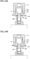
- a jig may be used when plastically deforming the proximal portion 34a of the third sheave 34A.
- a first jig 71 that is inserted into the distal portion of the boss 36A
- a second jig 72 that presses the outer circumferential surface 34o of the proximal portion 34a of the third sheave 34A in the radially inward direction
- a third jig 73 that is fitted into the second jig 72 so that it can slide up and down may be used.
- An outer circumferential surface 72a that is inclined from the vertical direction so as to extend radially outward while extending downward is formed in the lower portion of the second jig 72.
- An inner circumferential surface 73a that is inclined from the vertical direction so as to extend radially outward while extending downward is formed in the lower portion of the third jig 73.
- the inner circumferential surface 73a of the third jig 73 and the outer circumferential surface 72a of the second jig 72 come into contact with each other, and the lower portion of the second jig 72 is pushed by the third jig 73 in the radially inward direction.
- the lower portion of the second jig 72 presses the proximal portion 34a of the third sheave 34A in the radially inward direction.
- the proximal portion 34a of the third sheave 34A and the distal portion of the boss 36A are sandwiched between the first jig 71 and the second jig 72, and the proximal portion 34a of the third sheave 34A plastically deforms.
- first to third jigs 71 to 73 for example, the third sheave 34A and the boss 36A can be joined simply and inexpensively.
- the third sheave 34A and the boss 36A are joined together.
- the fourth sheave 34B and the boss 36B are joined together in a similar manner.
- the boss 36B is also formed with the first groove 51 and the second grooves 52.
- a portion of the proximal portion of the fourth sheave 34B plastically deforms to flow into the first groove 51 and the second grooves 52, thus joining together the fourth sheave 34B and the boss 36B.
- the step of joining together the third sheave 34A and the boss 36A and the step of joining together the fourth sheave 34B and the boss 36B are a part of the CVT 30 manufacturing process.
- Methods for manufacturing the CVT 30 include those in which the third sheave 34A and the boss 36A are joined together and those in which the fourth sheave 34B and the boss 36B are joined together.
- the boss 36A receives a load in the first direction A1 and a load in the second direction A2 of the third sheave 34A.
- the first groove 51 is formed on the boss 36A.
- the third sheave 34A includes the first plastically deformed portion 34p that is located in the first groove 51.
- the first groove 51 has the first surface 61 crossing the first direction A1. Therefore, the boss 36A can sufficiently receive the load in the first direction A1 of the third sheave 34A.
- the first groove 51 includes the second surface 62 crossing the second direction A2. Therefore, the boss 36A can sufficiently receive the load in the second direction A2 of the third sheave 34A. Therefore, the boss 36A can sufficiently support the load in the axial direction of the third sheave 34A.
- the boss 36A receives a load in the third direction A3 and a load in the fourth direction A4 of the third sheave 34A.
- the boss 36A is formed with the second grooves 52.
- the third sheave 34A includes the second plastically deformed portion 34q that is located in the second groove 52.
- the second groove 52 has the third surface 63 crossing the third direction A3. Therefore, the boss 36A can sufficiently receive the load in the third direction A3 of the third sheave 34A.
- the second groove 52 includes the fourth surface 64 crossing the fourth direction A4. Therefore, the boss 36A can sufficiently receive the load in the fourth direction A4 of the third sheave 34A. Therefore, the boss 36A can sufficiently support the load in the rotation direction of the third sheave 34A.
- the third sheave 34A and the boss 36A can be desirably joined together without welding together the third sheave 34A and the boss 36A.
- the first surface 61 is a surface that extends toward the radially outward direction R1 while extending in the first direction A1.
- the second surface 62 is a surface that extends in the radially outward direction R1 while extending in the second direction A2.
- the third surface 63 is a surface that extends in the radially outward direction R1 while extending in the third direction A3.
- the fourth surface 64 is a surface that extends in the radially outward direction R1 while extending in the fourth direction A4. Therefore, it is possible to relatively easily form the first groove 51 and the second grooves 52.
- the hardness of the material of the boss 36A is harder than the hardness of the material of the third sheave 34A.
- the elongation of the material of the third sheave 34A is greater than the elongation of the material of the boss 36A. Therefore, when joining together the third sheave 34A and the boss 36A, it is easier to plastically deform the proximal portion 34a of the third sheave 34A.
- a portion of the proximal portion 34a of the third sheave 34A is plastically deformed when the outer circumferential surface 34o of the proximal portion 34a of the third sheave 34A is pressed toward the radially inward direction, thereby making it easier to flow into the first groove 51 and the second grooves 52 of the boss 36A. Therefore, it is possible to desirably join together the third sheave 34A and the boss 36A.
- the first groove 51 extends completely around the outer circumferential surface 36s of the boss 36A. It is possible to relatively easily form the first groove 51.
- the first surface 61 and the second surface 62 are formed across the entirety in the circumferential direction of the boss 36A. Therefore, it is possible to ensure a relatively large area of the first surface 61 and the second surface 62. Therefore, the boss 36A can sufficiently support the load in the axial direction of the third sheave 34A.
- a plurality of second grooves 52 are arranged in the circumferential direction.
- a plurality of third surfaces 63 and a plurality of fourth surfaces 64 are formed in the circumferential direction. Therefore, it is possible to ensure a relatively large overall area of the third surfaces 63 and the fourth surfaces 64.
- the boss 36A can sufficiently support the load in the rotation direction of the sheave 34A.
- the sheave 34A is plastically deformed, thereby making it possible to firmly join the sheave 34A to the boss 36A.
- the second grooves 52 are open toward the second direction A2. Therefore, it is possible to easily form the second grooves 52.
- the second grooves 52 are connected to the first groove 51, and the second grooves 52 are open toward the first direction A1. This also makes it possible to easily form the second grooves 52.
- the length 52L of each second groove 52 in the first direction A1 is longer than the length 51L in the first direction A1 of the first groove 51. 52L>51L (see FIG. 4 ). Since the length 52L of each second groove 52 in the first direction A1 is relatively long, it is possible to ensure a relatively large area of the third surface 63 and the fourth surface 64. Therefore, the boss 36A can sufficiently support the load in the rotation direction of the third sheave 34A.
- the depth 51d of the first groove 51 (see FIG. 8 ) is deeper than the depth 52d of each second groove 52 (see FIG. 9 ). 51d>52d. Since the depth 51d of the first groove 51 is relatively deep, it is possible to ensure a relatively large area of the first surface 61 and the second surface 62.
- the boss 36A can sufficiently support the load in the axial direction of the third sheave 34A.
- the first groove 51 and the second grooves 52 have corner portions.
- the current density is high at the corner portions of the first groove 51 and the second grooves 52 so that the corner portions are more easily plated than other portions.
- the thickness of the plating film is likely to be non-uniform.
- the proximal portion 34a of the third sheave 34A when the thickness of the plating film is non-uniform, when the proximal portion 34a of the third sheave 34A is plastically deformed so as to flow into the first groove 51 and the second grooves 52, the proximal portion 34a may not smoothly flow into the inside of the first groove 51 and the second grooves 52, thus inhibiting uniform plastic deformation.
- the first groove 51 and the second grooves 52 are masked during the plating process, and the inside of the first groove 51 and the inside of the second grooves 52 are not plated. Therefore, a plastic deformation defect does not occur due to non-uniformity in the thickness of the plating film.
- the proximal portion 34a of the third sheave 34A can be uniformly plastically deformed, and it is possible to desirably join together the third sheave 34A and the boss 36A.
- portions, other than the first groove 51 and the second grooves 52, of the outer circumferential surface 36s of the boss 36A are plated, it is possible to suppress friction of those portions while the CVT 30 is in operation.
- the third sheave 34A and the boss 36A are joined together through plastic deformation of the third sheave 34A without welding together the third sheave 34A and the boss 36A. Therefore, before joining together the third sheave 34A and the boss 36A, only the third sheave 34A can be subjected to a heat treatment, etc., and only the boss 36A can be subjected to a heat treatment, etc. Thus, as compared with a case where the third sheave 34A and the boss 36A are welded together, the process to be performed on the third sheave 34A and the boss 36A is easier.
- first groove 51 extends completely around the outer circumferential surface 36s of the boss 36A in the embodiment described above, there is no particular limitation on the shape of the first groove 51.
- a plurality of first grooves 51 may be arranged in the circumferential direction of the boss 36A.
- the boss 36A may include a plurality of first grooves 51 having the first surface 61 and the second surface 62, extending in the circumferential direction and arranged in the circumferential direction, and a plurality of second grooves 52 having the third surface 63 and the fourth surface 64, extending in the first direction A1 and arranged in the circumferential direction.
- first groove 51 and the second grooves 52 are continuous with each other in the embodiment described above, the first groove 51 and the second grooves 52 do not need to be continues with each other as shown in FIG. 15 , for example.
- the first groove 51 and the second grooves 52 may be separate from each other.
- the first surface 61 and the second surface 62 are provided on the first groove 51, and the third surface 63 and the fourth surface 64 are provided on the second grooves 52.
- the groove 50 formed on the boss 36A includes the first groove 51 and the second grooves 52, which have different shapes. However, there is no particular limitation on the shape of the groove 50 of the boss 36A. For example, a plurality of grooves of the same shape may be formed on the boss 36A.
- the boss 36A may include a plurality of grooves having the first to fourth surfaces 61 to 64 and formed in the circumferential direction.
- the first surface 61 may be a surface that is perpendicular to the first direction A1.
- the second surface 62 may be a surface that is perpendicular to the second direction A2.
- the third surface 63 may be a surface that is perpendicular to the third direction A3.
- the fourth surface 64 may be a surface that is perpendicular to the fourth direction A4.
- the second grooves 52 do not need to be open toward the first direction A1.
- the second grooves 52 may have the first surface 61 crossing the first direction A1.
- the second grooves 52 do not need to be open toward the second direction A2.
- the second grooves 52 may have the second surface 62 crossing the second direction A2.
- first groove 51 is formed between the middle position of the boss 36A in the first direction A1 and the second grooves 52 in the embodiment described above, the first groove 51 may be formed closer to the distal end of the boss 36A relative to the second grooves 52.
- the second grooves 52 may be formed between the middle position of the boss 36A in the first direction A1 and the first groove 51.
- first groove 51 and the second grooves 52 do not need to be masked during the plating process.
- the second grooves 52 are formed by a knurl process in the embodiment described above, there is no particular limitation on the method for machining the second grooves 52.
- boss 36A is subjected to a plating process in the embodiment described above, there is no particular limitation thereto. Depending on the material of the boss 36A, there may be no plating process.
- first groove 51 may be formed after the second grooves 52 are formed.
- first groove 51 and the second grooves 52 may be formed simultaneously.
- the embodiment described above is an embodiment where the method for joining together the sheave and the boss through plastic deformation of the proximal portion of the sheave is applied to the secondary pulley 34. Note, however, that the application of the joining method is not limited to the secondary pulley 34. The joining method can be applied to the primary pulley 33.
- a motorcycle on which the CVT 30 is installed may be a type of a motorcycle other than a scooter.
- the CVT 30 may be installed on a vehicle other than a motorcycle.
- the CVT 30 may be any other straddled vehicle such as an auto tricycle, an ATV (All Terrain Vehicle), and the like. Note that a straddled vehicle refers to a vehicle that is straddled by a passenger.
- the CVT 30 may be installed on a vehicle other than a straddled vehicle.
- straddle-type vehicle or motor vehicle used herein is meant to include at least the following terms also used in the art: straddled vehicle, saddle-ride vehicle, saddle-straddling type vehicle, and includes: motorcycles and motorbikes as well as motor tricycles, quad bikes, All Terrain Vehicles (ATVs), scooters, mopeds and snowmobiles.
- ATVs All Terrain Vehicles
- scooters scooters
- mopeds snowmobiles.
- 30 Belt-type continuously variable transmission
- 33 Primary pulley
- 34 Secondary pulley
- 34A Third sheave
- 34a Proximal portion
- 34b Main body portion
- 34i Inner circumferential surface of proximal portion
- 34o Outer circumferential surface of proximal portion
- 36A Boss
- 36s Outer circumferential surface of boss
- 50 Groove
- 51 First groove
- 52 Second groove
- 61 First surface
- 62 Second surface
- 63 Third surface
- 64 Fourth surface.
Landscapes
- Engineering & Computer Science (AREA)
- General Engineering & Computer Science (AREA)
- Mechanical Engineering (AREA)
- Transmissions By Endless Flexible Members (AREA)
- Pulleys (AREA)
Abstract
Description
- The present invention relates to a belt-type continuously variable transmission and a method for manufacturing a belt-type continuously variable transmission. The present invention also relates to a straddle-type vehicle or saddle-ride type vehicle, such as a vehicle comprising or including a belt-type continuously variable transmission according to the present invention or manufactured according to the method of the present invention.
- A belt-type continuously variable transmission includes a primary pulley and a secondary pulley whose belt winding diameters are variable, and a belt wound around the primary pulley and the secondary pulley. The primary pulley includes a movable sheave and a fixed sheave supported on a primary shaft. The secondary pulley includes a movable sheave and a fixed sheave supported on a secondary shaft.
- For example, Japanese Laid-Open Patent Publication No.
2010-236647 2010-236647 - An object of at least one embodiment of at least one aspect of the present invention may be to obviate or at least mitigate one or more problems or disadvantages in the prior art.
- An object of at least one embodiment of at least one aspect of the present invention may be to provide a belt-type continuously variable transmission and/or a method for manufacturing a belt-type continuously variable transmission, with which the sheave and the boss can be desirably joined together without welding.
- Various aspects of the present invention are defined in the independent claims appended hereto. Some optional and/or preferred features are defined in the dependent claims appended hereto.
- According to a first aspect of the present invention there is provided a method for manufacturing a belt-type continuously variable transmission (CVT). The method may comprise or include one or more of the following steps: a step of preparing a cylindrical boss extending in a first direction; a step of forming a groove on an outer circumferential surface of the boss, wherein the groove may have a first surface crossing a first direction, a second surface crossing a second direction that may be an opposite direction to the first direction, a third surface crossing a third direction that may be a circumferential direction, and/or a fourth surface crossing a fourth direction that may be an opposite direction to the third direction; a step of preparing a sheave, wherein the sheave may include a proximal portion that has an inner circumferential surface and/or an outer circumferential surface and may extend in the first direction, and/or a main body portion that may be located radially outward relative to the proximal portion and may support a belt; a pre-press step of aligning the inner circumferential surface of the proximal portion of the sheave with the groove on the outer circumferential surface of the boss; and/or a step of pressing the outer circumferential surface of the proximal portion of the sheave toward a radially inward direction, thereby preferably plastically deforming the proximal portion until a portion of the proximal portion of the sheave may be fitted into the groove of the boss and/or the sheave may be joined to the boss.
- According to the manufacturing method set forth above, the outer circumferential surface of the proximal portion of the sheave may be pressed toward the radially inward direction, thereby plastically deforming the proximal portion. Moreover, by suppressing plastic deformation to the sheave end surface, a portion of the proximal portion of the sheave may fill the groove of the boss, thus joining the sheave to the boss. Herein, the groove may have the first surface crossing the first direction and the second surface crossing the second direction. Therefore, the boss can sufficiently receive the load in the first direction and in the second direction of the sheave. Thus, the boss can sufficiently support the load in the axial direction of the sheave. The groove also may have the third surface crossing the third direction and the fourth surface crossing the fourth direction. Therefore, the boss can sufficiently receive the load in the third direction and in the fourth direction of the sheave. Thus, the boss can sufficiently support the load in the rotation direction of the sheave. According to the manufacturing method set forth above, there is beneficially no need to weld together the sheave and the boss. It can be possible to desirably join together the sheave and the boss without welding.
- According to a preferred embodiment, the first surface may be a surface that extends toward the radially outward direction while extending in the first direction, the second surface may be a surface that extends toward the radially outward direction while extending in the second direction, the third surface may be a surface that extends toward the radially outward direction while extending in the third direction, and the fourth surface may be a surface that extends toward the radially outward direction while extending in the fourth direction.
- When machining the first surface crossing the first direction, a surface that extends toward the radially outward direction while extending in the first direction (hereinafter referred to as "slope") can be machined more easily than a vertical surface that perpendicularly crosses the first direction. This similarly holds true for the second surface crossing the second direction, the third surface crossing the third direction, and the fourth surface crossing the fourth direction. According to the embodiment set forth above, since at least one of the first to fourth surfaces may be a slope, it may be possible to relatively easily form the groove.
- According to a preferred embodiment, a hardness of a material of the boss may be harder than a hardness of a material of the sheave. According to a preferred embodiment, an elongation of a material of the sheave may be greater than an elongation of a material of the boss.
- According to the embodiment set forth above, a portion of the proximal portion may be plastically deformed when the outer circumferential surface of the proximal portion of the sheave is pressed toward the radially inward direction, thereby making it easier for the sheave material to flow into the groove of the boss, and/or making it easier for the sheave to be joined to the boss. Moreover, by suppressing plastic deformation to the sheave end surface, it may be possible to more desirably join together the sheave and the boss.
- According to a preferred embodiment, the groove may include a first groove that has the first surface and the second surface and may extend completely around the outer circumferential surface of the boss, and a plurality of second grooves that may have the third surface and the fourth surface and may be arranged in a circumferential direction.
- According to the embodiment set forth above, it may be possible to relatively easily form the first groove. Since the first surface or the second surface may be formed across the entirety in the circumferential direction of the boss, it may be possible to ensure a relatively large area of the first surface or the second surface. Since a plurality of third surfaces and/or a plurality of fourth surfaces may be formed in the circumferential direction, it may be possible to ensure a relatively large overall area of the third surfaces and the fourth surfaces. Thus, the sheave can be firmly joined to the boss through plastic deformation of the proximal portion of the sheave.
- According to a preferred embodiment, the groove may include a plurality of first grooves that have the first surface and the second surface and may be arranged in a circumferential direction, and a plurality of second grooves that may have the third surface and the fourth surface and may be arranged in a circumferential direction.
- According to the embodiment set forth above, since a plurality of first surfaces and a plurality of second surfaces may be formed in the circumferential direction, it may be possible to ensure a relatively large overall area of the first surfaces and the second surfaces. Since a plurality of third surfaces and a plurality of fourth surfaces may be formed in the circumferential direction, it may be possible to ensure a relatively large overall area of the third surfaces and the fourth surfaces. Thus, the sheave can be firmly joined to the boss through plastic deformation of the proximal portion of the sheave.
- According to a preferred embodiment, the second grooves may be open toward the second direction.
- According to the embodiment set forth above, it may be possible to (easily) form the second grooves.
- The first groove may be formed between a middle position of the boss in the first direction and the second grooves.
- The first groove and the second grooves may be connected to each other.
- According to a preferred embodiment, a length of each second groove in the first direction may be longer than a length of the first groove in the first direction.
- According to the embodiment set forth above, it may be possible to ensure a relatively large area of the third surface and the fourth surface. Thus, the boss can sufficiently receive the load in the rotation direction of the sheave.
- According to a preferred embodiment, a depth of the first groove may be deeper than a depth of each second groove.
- According to the embodiment set forth above, it may be possible to ensure a relatively large area of the first surface and the second surface. Thus, the boss can sufficiently receive the load in the axial direction of the sheave.
- According to a preferred embodiment, the method may include, after the step of forming the groove and before the pre-press step, a step of at least partially plating a portion of the outer circumferential surface other than the groove without plating an inside of the groove on the outer circumferential surface of the boss.
- The grooves on the boss may have corner portions. If the outer circumferential surface of the boss is entirely plated, the current density may be high at the corner portions of the grooves during the plating step so that the corner portions may be more easily plated than other portions. As a result, the thickness of the plating film may be likely to be non-uniform. However, when the thickness of the plating film is non-uniform, when the proximal portion of the sheave is plastically deformed so as to flow into the grooves, the proximal portion may not smoothly flow into the inside of the grooves, thus inhibiting uniform plastic deformation. According to the embodiment set forth above, however, the inside of the grooves may not be plated. Therefore, a plastic deformation defect may not occur due to non-uniformity in the thickness of the plating film. Thus, the proximal portion of the sheave can be uniformly plastically deformed, and it may be possible to desirably join together the sheave and the boss. On the other hand, since portions, other than the grooves, of the outer circumferential surface of the boss may be plated, it may be possible to suppress friction of those portions.
- According to a second aspect of the present invention there is provided a belt-type continuously variable transmission (CVT). The belt-type continuously variable transmission may comprise or including one or more of: a primary pulley which may be supported on a primary shaft, a secondary pulley which may be supported on a secondary shaft, and/or a belt which may be wound around the primary pulley and the secondary pulley. At least one of the primary pulley and the secondary pulley may have a cylindrical boss that may extend in a first direction and/or a sheave that may extend radially outward from the boss. A groove may be formed on an outer circumferential surface of the boss, wherein the groove may have one or more of: a first surface crossing the first direction, a second surface crossing a second direction that may be an opposite direction to the first direction, a third surface crossing a third direction that may be a circumferential direction, and a fourth surface crossing a fourth direction that may be an opposite direction to the third direction. The sheave may have a proximal portion that may extend in the first direction, and a main body portion that may be located radially outward relative to the proximal portion and may support the belt. The proximal portion of the sheave may comprise or include a plastically deformed portion that may be fitted into an inside of the groove of the boss. The sheave and the boss may be joined together through plastic deformation of the proximal portion of the sheave.
- According to a preferred embodiment, the first surface may be a surface that may extend toward the radially outward direction while extending in the first direction, the second surface may be a surface that may extend toward the radially outward direction while extending in the second direction, the third surface may be a surface that may extend toward the radially outward direction while extending in the third direction, and/or the fourth surface may be a surface that may extend toward the radially outward direction while extending in the fourth direction.
- According to a third aspect of the present invention there is provided a straddle-type vehicle comprising a belt-type continuously variable transmission (CVT) according to the second aspect of the present invention.
- According to one or more embodiments of one or more aspects of the present invention, it is possible to provide a belt-type continuously variable transmission and a method for manufacturing a belt-type continuously variable transmission, with which the sheave and the boss can be desirably joined together without welding.
- Embodiments of the present invention will now be described by way of example only, and with reference to the accompanying drawings, which are:
-
FIG. 1 a side view of a motorcycle including a belt-type continuously variable transmission according to an embodiment of the present invention; -
FIG. 2 a cross-sectional view of a power unit; -
FIG. 3 a cross-sectional view of a portion of the power unit; -
FIG. 4 a perspective view of the distal portion of the boss of the secondary pulley; -
FIG. 5 a partial enlarged view of the end surface of the boss; -
FIG. 6 a cross-sectional view taken along line VI-VI ofFIG. 5 ; -
FIG. 7 a cross-sectional view taken along line VII-VII ofFIG. 5 ; -
FIG. 8 an enlarged view of the first groove, and is a longitudinal sectional view passing through the center line of the boss; -
FIG. 9 an enlarged view of a second groove, and is a cross sectional view perpendicular to the center line of the boss; -
FIG. 10 a longitudinal sectional view of the third sheave; -
FIG. 11 a flow chart of a method for joining together the third sheave and the boss; -
FIG. 12 a diagram illustrating the plastic deformation of the proximal portion of the third sheave into the first groove; -
FIG. 13 a diagram illustrating the plastic deformation of the proximal portion of the third sheave into the first groove and the second groove; -
FIG. 14A a cross-sectional view of jigs, the third sheave and the boss before the proximal portion of the third sheave is pressed; -
FIG. 14B a cross-sectional view of jigs, the third sheave and the boss after the proximal portion of the third sheave is pressed; and -
FIG. 15 a diagram equivalent toFIG. 5 according to another embodiment of the present invention. -
FIG. 1 illustrates a motorcycle 1 including a belt-type continuously variable transmission (hereinafter referred to as "CVT") 30 according to one embodiment. The motorcycle 1 includes afront wheel 3, arear wheel 4, apower unit 10 for driving therear wheel 4, aseat 6, and a handle 5. Herein, the motorcycle 1 is a scooter. Note however that there is no particular limitation thereto. -
FIG. 2 is a cross-sectional view of thepower unit 10. Thepower unit 10 includes an internal combustion engine (hereinafter referred to as "engine") 20 and aCVT 30. - The
engine 20 includes acrankcase 21, acylinder body 22 connected to thecrankcase 21, acylinder head 23 connected to thecylinder body 22, and acylinder head cover 24 connected to thecylinder head 23. Theengine 20 also includes acrankshaft 26 rotatably supported on thecrankcase 21 with abearing 25 therebetween, a connectingrod 27 linked to thecrankshaft 26, apiston 28 linked to the connectingrod 27, and anignition device 19. Thepiston 28 is arranged inside acylinder 22A formed in thecylinder body 22. Thecrankshaft 26 extends in the vehicle width direction. Agenerator 29 is attached to the right end portion of thecrankshaft 26. Although not shown in the figures, thecylinder head 23 is provided with an intake valve and an exhaust valve. - In the present embodiment, a
primary shaft 31 is arranged leftward of thecrankshaft 26. Thecrankshaft 26 and theprimary shaft 31 are integral with each other. Note, however, that there is no particular limitation thereto. Theprimary shaft 31 may be separate from thecrankshaft 26. TheCVT 30 includes theprimary shaft 31, asecondary shaft 32 parallel to theprimary shaft 31, aprimary pulley 33 supported on theprimary shaft 31, a secondary pulley 34 supported on thesecondary shaft 32, and aV belt 35 wound around theprimary pulley 33 and the secondary pulley 34. TheCVT 30 is arranged inside atransmission case 30A. In the present embodiment, thesecondary shaft 32 is arranged rearward of theprimary shaft 31, and the secondary pulley 34 is arranged rearward of theprimary pulley 33. - The
primary pulley 33 includes afirst sheave 33A that is attached so as to be un-rotatable and axially un-movable relative to theprimary shaft 31, and asecond sheave 33B that is attached so as to be un-rotatable and axially movable relative to theprimary shaft 31. Thefirst sheave 33A and thesecond sheave 33B rotate together with theprimary shaft 31. As thesecond sheave 33B moves in the axial direction, the gap between thefirst sheave 33A and thesecond sheave 33B changes. This changes the winding diameter of theV belt 35 around theprimary pulley 33. Note that theprimary pulley 33 and theV belt 35 are shown on the upper side and on the lower side of theprimary shaft 31 ofFIG. 2 , with thesecond sheave 33B being at different positions. - The secondary pulley 34 includes a
boss 36A that is supported so as to be rotatable and axially un-movable relative to thesecondary shaft 32, athird sheave 34A joined to theboss 36A, a boss 36B supported so as to be rotatable and axially movable relative to thesecondary shaft 32, and afourth sheave 34B joined to the boss 36B. Abearing 17 and abearing 18 are provided between theboss 36A and thesecondary shaft 32. Theboss 36A is rotatably supported on thesecondary shaft 32 via thebearing 17 and thebearing 18. The boss 36B is attached so as to be unrotatable and axially movable relative to theboss 36A. The boss 36B rotates together with theboss 36A. Although the details will be described later, thethird sheave 34A and theboss 36A are joined together through plastic deformation of thethird sheave 34A. Thefourth sheave 34B and the boss 36B are joined together through plastic deformation of thefourth sheave 34B. - The
third sheave 34A and thefourth sheave 34B rotate together with theboss 36A and the boss 36B. As thefourth sheave 34B moves in the axial direction, the gap between thethird sheave 34A and thefourth sheave 34B changes. This changes the winding diameter of theV belt 35 around the secondary pulley 34. Note that the secondary pulley 34 and theV belt 35 are shown on the upper side and on the lower side of thesecondary shaft 32 ofFIG. 2 , with thefourth sheave 34B being at different positions. - The
CVT 30 includes aspring 38 that urges thefourth sheave 34B toward thethird sheave 34A. Thespring 38 urges thefourth sheave 34B rightward. - A
centrifugal clutch 40 is provided at the left end portion of thesecondary shaft 32. A drivingportion 41 of the centrifugal clutch 40 is fixed to theboss 36A and rotates together with theboss 36A. A drivenportion 42 of the centrifugal clutch 40 is fixed to thesecondary shaft 32 and rotates together with thesecondary shaft 32. When the rotation speed of the drivingportion 41 becomes greater than or equal to a predetermined rotation speed, acentrifugal weight 43 provided on the drivingportion 41 moves radially outward of thesecondary shaft 32, thereby connecting together the drivingportion 41 and the drivenportion 42. That is, the centrifugal clutch 40 is connected. On the other hand, when the rotation speed of the drivingportion 41 is less than the predetermined rotation speed, the connection between the drivingportion 41 and the drivenportion 42 is disengaged. That is, the centrifugal clutch 40 is disconnected. When the centrifugal clutch 40 is connected, the rotational force of theboss 36A is transmitted to thesecondary shaft 32, and the secondary pulley 34 and thesecondary shaft 32 rotate together. When the centrifugal clutch 40 is disconnected, the rotational force from theboss 36A to thesecondary shaft 32 is blocked, and the secondary pulley 34 rotates relative to thesecondary shaft 32. - The
power unit 10 includes anoutput shaft 45 parallel to thesecondary shaft 32. Therear wheel 4 is linked to theoutput shaft 45. As shown inFIG. 3 , amiddle shaft 46 is arranged between thesecondary shaft 32 and theoutput shaft 45. Thesecondary shaft 32 is formed with agear 32a, and themiddle shaft 46 is provided with agear 46a that meshes with thegear 32a. Themiddle shaft 46 is formed with agear 46b, and theoutput shaft 45 is provided with agear 45a that meshes with thegear 46b. Thus, thesecondary shaft 32 is linked to themiddle shaft 46 via thegear 32a and thegear 46a, and themiddle shaft 46 is linked to theoutput shaft 45 via thegear 46b and thegear 45a. Therefore, the rotational force of thesecondary shaft 32 is transmitted to theoutput shaft 45, and the rotational force is transmitted from theoutput shaft 45 to therear wheel 4. - The
power unit 10 is configured as described above. As described above, the secondary pulley 34 of theCVT 30 is formed by joining together thethird sheave 34A and theboss 36A through plastic deformation of thethird sheave 34A, and joining together thefourth sheave 34B and the boss 36B through plastic deformation of thefourth sheave 34B. Next, theboss 36A and thethird sheave 34A before being joined together will be described. -
FIG. 4 is a perspective view of the distal portion of theboss 36A before thethird sheave 34A is joined thereto.FIG. 5 is a partial enlarged view of the end surface of theboss 36A. That is,FIG. 5 is a partial enlarged view as theboss 36A is seen from the right side.FIG. 6 is a cross-sectional view taken along line VI-VI ofFIG. 5 , andFIG. 7 is a cross-sectional view taken along line VII-VII ofFIG. 5 . In the following description, the directions represented by arrows A1, A2, A3 and A4 will be referred to as the first direction, the second direction, the third direction and the fourth direction, respectively. As shown inFIG. 4 , the first direction A1 is the direction in which theboss 36A extends. The second direction A2 is the opposite direction to the first direction A1. The third direction A3 is a circumferential direction of theboss 36A. The fourth direction A4 is the opposite direction to the third direction A3. Thereference sign 36c denotes the center line of theboss 36A. The reference sign R1 denotes radially outward of theboss 36A. - As shown in
FIG. 4 , the distal portion of theboss 36A is formed with agroove 50. Thegroove 50 includes afirst groove 51 that extends completely around an outercircumferential surface 36s of theboss 36A, and a plurality ofsecond grooves 52 arranged in the circumferential direction. - As shown in
FIG. 6 , thefirst groove 51 includes afirst surface 61 crossing the first direction A1, and asecond surface 62 crossing the second direction A2. Although thefirst surface 61 may perpendicularly cross the first direction A1, it herein slantly (obliquely) crosses the first direction A1. Thefirst surface 61 is a surface that extends toward the radially outward direction R1 while extending in the first direction A1, and is a slope that is inclined from the first direction A1. Similarly, although thesecond surface 62 may perpendicularly cross the second direction A2, it herein slantly (obliquely) crosses the second direction A2. Thesecond surface 62 is a surface that extends toward the radially outward direction R1 while extending in the second direction A2, and is a slope that is inclined from the second direction A2. In the present embodiment, thefirst surface 61 and thesecond surface 62 each extend completely around acenter line 36c of theboss 36A. Note, however, that there is no particular limitation thereto. Thefirst surface 61 and thesecond surface 62 may be formed intermittently around thecenter line 36c. - As shown in
FIG. 8 , on a longitudinal section passing through thecenter line 36c of theboss 36A, the angle θ1 formed between the first direction A1 and thefirst surface 61 may be equal to, or different from, the angle θ2 formed between the second direction A2 and thesecond surface 62. While there is no particular limitation on the angles θ1 and θ2, such may be in the range of 40° to 50° or in the range of 30° to 60°, for example. In the present embodiment, θ1=θ2=47.5°. - As shown in
FIG. 5 , thesecond groove 52 includes athird surface 63 crossing the third direction A3, and afourth surface 64 crossing the fourth direction A4. Although thethird surface 63 may perpendicularly cross the third direction A3, it herein slantly (obliquely) crosses the third direction A3. Thethird surface 63 is a surface that extends toward the radially outward direction R1 while extending in the third direction A3, and is a slope that is inclined from the third direction A3. Similarly, although thefourth surface 64 may perpendicularly cross the fourth direction A4, it herein slantly (obliquely) crosses the fourth direction A4. Thefourth surface 64 is a surface that extends toward the radially outward direction R1 while extending in the fourth direction A4, and is a slope that is inclined from the fourth direction A4. - As shown in
FIG. 9 , on a cross-section perpendicular to thecenter line 36c of theboss 36A, the angle θ3 formed between the third direction A3 and thethird surface 63 and the angle θ4 formed between the fourth direction A4 and thefourth surface 64 may be equal to each other or different from each other. While there is no particular limitation on the angles θ3 and θ4, such may be in the range of 40° to 50° or in the range of 30° to 60°, for example. In the present embodiment, θ3=θ4=45°. The angles θ1 to θ4 may be all equal. Any one of the angles θ1 to θ4 may be different from any other one or ones of the angles θ1 to θ4. The angles θ1 to θ4 may all be different angles. - In the present embodiment, the
depth 51d of the first groove 51 (seeFIG. 8 ) is deeper than thedepth 52d of each second groove 52 (seeFIG. 9 ). 51d>52d. Note, however, that there is no limitation thereto. It may be 51d=52d or may be 51d<52d. Note that thedepth 51d of thefirst groove 51 and thedepth 52d of eachsecond groove 52 are set based on the thrust load, for example. Herein, the thrust load corresponds to the load in the direction A1 or A2 in the figures. - As shown in
FIG. 4 , thesecond grooves 52 are formed closer to the distal end of theboss 36A relative to thefirst groove 51. Thefirst groove 51 is formed between the middle position of theboss 36A in the first direction A1 and thesecond grooves 52. - As shown in
FIG. 7 , in the present embodiment, thefirst groove 51 and thesecond grooves 52 are connected to each other. Thefirst groove 51 and thesecond grooves 52 are continuous with each other. Note, however, that there is no limitation thereto. Thefirst groove 51 and thesecond grooves 52 may be separate from each other. - As shown in
FIG. 4 andFIG. 7 , thesecond grooves 52 are formed at the distal end of theboss 36A. Thesecond grooves 52 are open toward the second direction A2. Also, since thesecond grooves 52 are connected to thefirst groove 51, such are open toward the first direction A1. Note, however, that there is no limitation thereto. - As shown in
FIG. 4 , thelength 52L of eachsecond groove 52 in the first direction A1 is longer than thelength 51L of thefirst groove 51 in the first direction A1. 51L<52L. Note, however, that there is no limitation thereto. It may be 51L=52L or may be 51L>52L. Note that thelength 51L of thefirst groove 51 and thelength 52L of eachsecond groove 52 are set based on the torque load, for example. Herein, the torque load corresponds to the load in the direction A3 or A4 in the figures. -
FIG. 10 is a longitudinal sectional view of thethird sheave 34A before being joined. Thethird sheave 34A includes aproximal portion 34a extending in the first direction A1, and amain body portion 34b located radially outward R1 relative to theproximal portion 34a. Theproximal portion 34a is formed in a tubular shape, and has an innercircumferential surface 34i and an outer circumferential surface 34o. Themain body portion 34b is formed integral with theproximal portion 34a, and extends radially outward R1 from theproximal portion 34a. A portion of themain body portion 34b is inclined from the radial direction so as to extend toward the second direction A2 while extending radially outward R1. This portion of themain body portion 34b is a portion that is to be in contact with theV belt 35 and is a portion that supports the V belt 35 (seeFIG. 2 ). - Although there is no particular limitation on the materials of the
boss 36A and thethird sheave 34A, the material of theboss 36A is S35C (carbon steel for machine structure) and the material of thethird sheave 34A is SPCC (cold rolled steel plate) in the present embodiment. The hardness of the material of theboss 36A is harder than the hardness of the material of thethird sheave 34A. Note that the "hardness of the material of the boss" as used in the present specification refers to the hardness of the material (S35C in the present embodiment) of the boss. Where the boss is subjected to a surface treatment, the "hardness of the material of the boss" refers to the hardness of the material of the boss but not the hardness of the surface after the surface treatment. Similarly, the "hardness of the material of the sheave" refers to the hardness of the material (SPCC in the present embodiment) of the sheave. Where the sheave is subjected to a surface treatment, the "hardness of the material of the sheave" refers to the hardness of the material of the sheave but not the hardness of the surface after the surface treatment. Note that the "hardness" is herein assumed to mean Rockwell hardness. Note, however, that the "hardness" is not limited to Rockwell hardness. For example, the "hardness" may be Vickers hardness. The materials and the hardness described above are merely illustrative and there is no particular limitation thereto. - In the present embodiment, the elongation of the material of the
third sheave 34A is greater than the elongation of the material of theboss 36A. Note that the "elongation" is the rate of change between the initial length and the length upon fracture. Where L0 denotes the initial length and Lf denotes the length upon fracture, the elongation δ is expressed as δ=[(Lf-L0)/L0]×100(%). In the present specification, "the elongation of the material of the sheave" and "the elongation of the material of the boss" refer respectively to the elongation of the material (SPCC in the present embodiment) of the sheave and the elongation of the material (S35C in the present embodiment) of the boss. - Next, referring to the flow chart of
FIG. 11 , a method for joining together thethird sheave 34A and theboss 36A will be described. - First, a
cylindrical boss 36A is prepared (step S1). Then, thefirst groove 51 described above is formed on the outercircumferential surface 36s of the distal portion of theboss 36A (step S2). Then, thesecond grooves 52 described above are formed on the outercircumferential surface 36s of the distal portion of theboss 36A (step S3). Thus, theboss 36A (seeFIG. 4 ) is obtained, which is formed with thefirst groove 51 and thesecond grooves 52 on the distal portion thereof. Note that there is no particular limitation on the method for machining thefirst groove 51 and thesecond grooves 52. In the present embodiment, thefirst groove 51 is formed by a cutting process. Thesecond grooves 52 are formed by a rolling knurl process. - Then, after the
boss 36A is subjected to induction hardening, a surface polishing process is performed. Thereafter, portions of theboss 36A where thefirst groove 51 and thesecond grooves 52 are formed are masked, and the other portions of theboss 36A are subjected to a plating process (step S4). In the present embodiment, a chromium plating process is performed. Thereafter, a polishing process is performed again. - Before or after steps S1 to S4, or simultaneously with steps S1 to S4, the
third sheave 34A is prepared (step S5). - Then, a pre-press step of step S6 is performed. In the pre-press step, the distal portion of the
boss 36A is press-fitted into theproximal portion 34a of thethird sheave 34A (seeFIG. 10 ). Thus, the innercircumferential surface 34i of theproximal portion 34a is aligned with thefirst groove 51 and thesecond grooves 52. - Then, the outer circumferential surface 34o of the
proximal portion 34a of thethird sheave 34A is pressed toward the radially inward direction, thereby plastically deforming theproximal portion 34a (step S7). That is, the outer circumferential surface 34o of theproximal portion 34a of thethird sheave 34A is pressed toward the radially inward direction until a portion of theproximal portion 34a of thethird sheave 34A is fitted into thefirst groove 51 and thesecond grooves 52 of theboss 36A and thethird sheave 34A is joined to theboss 36A. Thus, as shown inFIG. 12 , theproximal portion 34a of thethird sheave 34A plastically deforms, and a portion of theproximal portion 34a flows into thefirst groove 51 of theboss 36A. Thethird sheave 34A then has a first plasticallydeformed portion 34p that is located in thefirst groove 51. As shown inFIG. 13 , theproximal portion 34a of thesheave 34A plastically deforms, and another portion of theproximal portion 34a flows into thesecond groove 52 of theboss 36A. Thesecond sheave 34A then has a second plasticallydeformed portion 34q that is located in thesecond groove 52. - Note that a jig may be used when plastically deforming the
proximal portion 34a of thethird sheave 34A. For example, as shown inFIG. 14A , afirst jig 71 that is inserted into the distal portion of theboss 36A, a second jig 72 that presses the outer circumferential surface 34o of theproximal portion 34a of thethird sheave 34A in the radially inward direction, and athird jig 73 that is fitted into the second jig 72 so that it can slide up and down may be used. An outercircumferential surface 72a that is inclined from the vertical direction so as to extend radially outward while extending downward is formed in the lower portion of the second jig 72. An innercircumferential surface 73a that is inclined from the vertical direction so as to extend radially outward while extending downward is formed in the lower portion of thethird jig 73. As thethird jig 73 is moved downward, the innercircumferential surface 73a of thethird jig 73 and the outercircumferential surface 72a of the second jig 72 come into contact with each other, and the lower portion of the second jig 72 is pushed by thethird jig 73 in the radially inward direction. As a result, the lower portion of the second jig 72 presses theproximal portion 34a of thethird sheave 34A in the radially inward direction. Theproximal portion 34a of thethird sheave 34A and the distal portion of theboss 36A are sandwiched between thefirst jig 71 and the second jig 72, and theproximal portion 34a of thethird sheave 34A plastically deforms. By using such first tothird jigs 71 to 73, for example, thethird sheave 34A and theboss 36A can be joined simply and inexpensively. - As described above, the
third sheave 34A and theboss 36A are joined together. Note that although detailed description is omitted, thefourth sheave 34B and the boss 36B are joined together in a similar manner. As with theboss 36A, the boss 36B is also formed with thefirst groove 51 and thesecond grooves 52. As the proximal portion of thefourth sheave 34B is pressed in the radially inward direction, a portion of the proximal portion of thefourth sheave 34B plastically deforms to flow into thefirst groove 51 and thesecond grooves 52, thus joining together thefourth sheave 34B and the boss 36B. - The step of joining together the
third sheave 34A and theboss 36A and the step of joining together thefourth sheave 34B and the boss 36B are a part of theCVT 30 manufacturing process. Methods for manufacturing theCVT 30 include those in which thethird sheave 34A and theboss 36A are joined together and those in which thefourth sheave 34B and the boss 36B are joined together. - As described above, according to the present embodiment, there is no need to weld together the
third sheave 34A and theboss 36A. Therefore, materials that are difficult to weld together can be used as the materials of thethird sheave 34A and theboss 36A. Since there is no need for welding, it is possible to inexpensively join together thethird sheave 34A and theboss 36A. - Now, the
boss 36A receives a load in the first direction A1 and a load in the second direction A2 of thethird sheave 34A. In the present embodiment, thefirst groove 51 is formed on theboss 36A. Thethird sheave 34A includes the first plasticallydeformed portion 34p that is located in thefirst groove 51. Herein, thefirst groove 51 has thefirst surface 61 crossing the first direction A1. Therefore, theboss 36A can sufficiently receive the load in the first direction A1 of thethird sheave 34A. Thefirst groove 51 includes thesecond surface 62 crossing the second direction A2. Therefore, theboss 36A can sufficiently receive the load in the second direction A2 of thethird sheave 34A. Therefore, theboss 36A can sufficiently support the load in the axial direction of thethird sheave 34A. - The
boss 36A receives a load in the third direction A3 and a load in the fourth direction A4 of thethird sheave 34A. In the present embodiment, theboss 36A is formed with thesecond grooves 52. Thethird sheave 34A includes the second plasticallydeformed portion 34q that is located in thesecond groove 52. Herein, thesecond groove 52 has thethird surface 63 crossing the third direction A3. Therefore, theboss 36A can sufficiently receive the load in the third direction A3 of thethird sheave 34A. Thesecond groove 52 includes thefourth surface 64 crossing the fourth direction A4. Therefore, theboss 36A can sufficiently receive the load in the fourth direction A4 of thethird sheave 34A. Therefore, theboss 36A can sufficiently support the load in the rotation direction of thethird sheave 34A. - Therefore, according to the present embodiment and the present invention, the
third sheave 34A and theboss 36A can be desirably joined together without welding together thethird sheave 34A and theboss 36A. - In the present embodiment, the
first surface 61 is a surface that extends toward the radially outward direction R1 while extending in the first direction A1. Thesecond surface 62 is a surface that extends in the radially outward direction R1 while extending in the second direction A2. Thethird surface 63 is a surface that extends in the radially outward direction R1 while extending in the third direction A3. Thefourth surface 64 is a surface that extends in the radially outward direction R1 while extending in the fourth direction A4. Therefore, it is possible to relatively easily form thefirst groove 51 and thesecond grooves 52. - In the present embodiment, the hardness of the material of the
boss 36A is harder than the hardness of the material of thethird sheave 34A. The elongation of the material of thethird sheave 34A is greater than the elongation of the material of theboss 36A. Therefore, when joining together thethird sheave 34A and theboss 36A, it is easier to plastically deform theproximal portion 34a of thethird sheave 34A. A portion of theproximal portion 34a of thethird sheave 34A is plastically deformed when the outer circumferential surface 34o of theproximal portion 34a of thethird sheave 34A is pressed toward the radially inward direction, thereby making it easier to flow into thefirst groove 51 and thesecond grooves 52 of theboss 36A. Therefore, it is possible to desirably join together thethird sheave 34A and theboss 36A. - According to the present embodiment, the
first groove 51 extends completely around the outercircumferential surface 36s of theboss 36A. It is possible to relatively easily form thefirst groove 51. Thefirst surface 61 and thesecond surface 62 are formed across the entirety in the circumferential direction of theboss 36A. Therefore, it is possible to ensure a relatively large area of thefirst surface 61 and thesecond surface 62. Therefore, theboss 36A can sufficiently support the load in the axial direction of thethird sheave 34A. A plurality ofsecond grooves 52 are arranged in the circumferential direction. A plurality ofthird surfaces 63 and a plurality offourth surfaces 64 are formed in the circumferential direction. Therefore, it is possible to ensure a relatively large overall area of thethird surfaces 63 and the fourth surfaces 64. Thus, theboss 36A can sufficiently support the load in the rotation direction of thesheave 34A. According to the present embodiment, thesheave 34A is plastically deformed, thereby making it possible to firmly join thesheave 34A to theboss 36A. - According to the present embodiment, the
second grooves 52 are open toward the second direction A2. Therefore, it is possible to easily form thesecond grooves 52. Thesecond grooves 52 are connected to thefirst groove 51, and thesecond grooves 52 are open toward the first direction A1. This also makes it possible to easily form thesecond grooves 52. - According to the present embodiment, the
length 52L of eachsecond groove 52 in the first direction A1 is longer than thelength 51L in the first direction A1 of thefirst groove 51. 52L>51L (seeFIG. 4 ). Since thelength 52L of eachsecond groove 52 in the first direction A1 is relatively long, it is possible to ensure a relatively large area of thethird surface 63 and thefourth surface 64. Therefore, theboss 36A can sufficiently support the load in the rotation direction of thethird sheave 34A. - According to the present embodiment, the
depth 51d of the first groove 51 (seeFIG. 8 ) is deeper than thedepth 52d of each second groove 52 (seeFIG. 9 ). 51d>52d. Since thedepth 51d of thefirst groove 51 is relatively deep, it is possible to ensure a relatively large area of thefirst surface 61 and thesecond surface 62. Theboss 36A can sufficiently support the load in the axial direction of thethird sheave 34A. - Now, the
first groove 51 and thesecond grooves 52 have corner portions. In the plating process (see step S4), if the outercircumferential surface 36s of theboss 36A is entirely subjected to a plating process, the current density is high at the corner portions of thefirst groove 51 and thesecond grooves 52 so that the corner portions are more easily plated than other portions. As a result, the thickness of the plating film is likely to be non-uniform. However, when the thickness of the plating film is non-uniform, when theproximal portion 34a of thethird sheave 34A is plastically deformed so as to flow into thefirst groove 51 and thesecond grooves 52, theproximal portion 34a may not smoothly flow into the inside of thefirst groove 51 and thesecond grooves 52, thus inhibiting uniform plastic deformation. According to the present embodiment, however, thefirst groove 51 and thesecond grooves 52 are masked during the plating process, and the inside of thefirst groove 51 and the inside of thesecond grooves 52 are not plated. Therefore, a plastic deformation defect does not occur due to non-uniformity in the thickness of the plating film. Thus, theproximal portion 34a of thethird sheave 34A can be uniformly plastically deformed, and it is possible to desirably join together thethird sheave 34A and theboss 36A. On the other hand, since portions, other than thefirst groove 51 and thesecond grooves 52, of the outercircumferential surface 36s of theboss 36A are plated, it is possible to suppress friction of those portions while theCVT 30 is in operation. - As described above, according to the present embodiment and the present invention, the
third sheave 34A and theboss 36A are joined together through plastic deformation of thethird sheave 34A without welding together thethird sheave 34A and theboss 36A. Therefore, before joining together thethird sheave 34A and theboss 36A, only thethird sheave 34A can be subjected to a heat treatment, etc., and only theboss 36A can be subjected to a heat treatment, etc. Thus, as compared with a case where thethird sheave 34A and theboss 36A are welded together, the process to be performed on thethird sheave 34A and theboss 36A is easier. - Note that the effects described above can similarly be achieved also for the
fourth sheave 34B and the boss 36B. - While one embodiment has been described above, the embodiment is merely an example. Various other embodiments are possible. Next, examples of other embodiments will be briefly described.
- While the
first groove 51 extends completely around the outercircumferential surface 36s of theboss 36A in the embodiment described above, there is no particular limitation on the shape of thefirst groove 51. For example, as shown inFIG. 15 , a plurality offirst grooves 51 may be arranged in the circumferential direction of theboss 36A. Theboss 36A may include a plurality offirst grooves 51 having thefirst surface 61 and thesecond surface 62, extending in the circumferential direction and arranged in the circumferential direction, and a plurality ofsecond grooves 52 having thethird surface 63 and thefourth surface 64, extending in the first direction A1 and arranged in the circumferential direction. - While the
first groove 51 and thesecond grooves 52 are continuous with each other in the embodiment described above, thefirst groove 51 and thesecond grooves 52 do not need to be continues with each other as shown inFIG. 15 , for example. Thefirst groove 51 and thesecond grooves 52 may be separate from each other. - In the embodiment described above, the
first surface 61 and thesecond surface 62 are provided on thefirst groove 51, and thethird surface 63 and thefourth surface 64 are provided on thesecond grooves 52. Thegroove 50 formed on theboss 36A includes thefirst groove 51 and thesecond grooves 52, which have different shapes. However, there is no particular limitation on the shape of thegroove 50 of theboss 36A. For example, a plurality of grooves of the same shape may be formed on theboss 36A. Theboss 36A may include a plurality of grooves having the first tofourth surfaces 61 to 64 and formed in the circumferential direction. - The
first surface 61 may be a surface that is perpendicular to the first direction A1. Similarly, thesecond surface 62 may be a surface that is perpendicular to the second direction A2. Thethird surface 63 may be a surface that is perpendicular to the third direction A3. Thefourth surface 64 may be a surface that is perpendicular to the fourth direction A4. - In the embodiment described above, the
second grooves 52 do not need to be open toward the first direction A1. Thesecond grooves 52 may have thefirst surface 61 crossing the first direction A1. Thesecond grooves 52 do not need to be open toward the second direction A2. Thesecond grooves 52 may have thesecond surface 62 crossing the second direction A2. - While the
first groove 51 is formed between the middle position of theboss 36A in the first direction A1 and thesecond grooves 52 in the embodiment described above, thefirst groove 51 may be formed closer to the distal end of theboss 36A relative to thesecond grooves 52. Thesecond grooves 52 may be formed between the middle position of theboss 36A in the first direction A1 and thefirst groove 51. - The
length 52L of eachsecond groove 52 in the first direction A1 does not always need to be longer than thelength 51L of thefirst groove 51 in the first direction A1. It may be 52L=51L or may be 52L<51L. - The
depth 51d of thefirst groove 51 does not always need to be deeper than thedepth 52d of eachsecond groove 52. It may be 51d=52d or may be 51d<52d. - Where a relatively uniform plating film can be formed on the
first groove 51 and thesecond grooves 52, thefirst groove 51 and thesecond grooves 52 do not need to be masked during the plating process. - While the
second grooves 52 are formed by a knurl process in the embodiment described above, there is no particular limitation on the method for machining thesecond grooves 52. - While the
boss 36A is subjected to a plating process in the embodiment described above, there is no particular limitation thereto. Depending on the material of theboss 36A, there may be no plating process. - While the
second grooves 52 are formed after thefirst groove 51 is formed in the embodiment described above, the order is not limited to this. Thefirst groove 51 may be formed after thesecond grooves 52 are formed. Alternatively, thefirst groove 51 and thesecond grooves 52 may be formed simultaneously. - The embodiment described above is an embodiment where the method for joining together the sheave and the boss through plastic deformation of the proximal portion of the sheave is applied to the secondary pulley 34. Note, however, that the application of the joining method is not limited to the secondary pulley 34. The joining method can be applied to the
primary pulley 33. - A motorcycle on which the
CVT 30 is installed may be a type of a motorcycle other than a scooter. TheCVT 30 may be installed on a vehicle other than a motorcycle. TheCVT 30 may be any other straddled vehicle such as an auto tricycle, an ATV (All Terrain Vehicle), and the like. Note that a straddled vehicle refers to a vehicle that is straddled by a passenger. TheCVT 30 may be installed on a vehicle other than a straddled vehicle. - It will be appreciated that the embodiments of the present invention hereinbefore described are given by way of example only, and are not intended to limit the scope of the invention in any way. The steps of the method of the present invention may be carried out in the sequence presented or claimed or in any other suitable sequence.
- It will be appreciated that any of the features of any of the disclosed embodiments may be provided in combination with any of the features of the statements of invention given in the Summary of Invention and/or any of the other disclosed embodiments either individually or in combination.
- It will be appreciated that the term "straddle-type" vehicle or motor vehicle used herein, and as used in the art, is meant to include at least the following terms also used in the art:
straddled vehicle, saddle-ride vehicle, saddle-straddling type vehicle, and includes: motorcycles and motorbikes as well as motor tricycles, quad bikes, All Terrain Vehicles (ATVs), scooters, mopeds and snowmobiles. - 30: Belt-type continuously variable transmission, 33: Primary pulley, 34: Secondary pulley, 34A: Third sheave, 34a: Proximal portion, 34b: Main body portion, 34i: Inner circumferential surface of proximal portion, 34o: Outer circumferential surface of proximal portion, 36A: Boss, 36s: Outer circumferential surface of boss, 50: Groove, 51: First groove, 52: Second groove, 61: First surface, 62: Second surface, 63: Third surface, 64: Fourth surface.
Claims (15)
- A method for manufacturing a belt-type continuously variable transmission, the method comprising:a step (S1) of preparing a cylindrical boss (36A) extending in a first direction (A1);a step (S2, S3) of forming a groove (50) on an outer circumferential surface (36s) of the boss (36A), wherein the groove (50) has a first surface (61) crossing a first direction (A1), a second surface (62) crossing a second direction (A2) that is an opposite direction to the first direction (A1), a third surface (63) crossing a third direction (A3) that is a circumferential direction, and a fourth surface (64) crossing a fourth direction (A4) that is an opposite direction to the third direction (A3);a step (S5) of preparing a sheave (34A), wherein the sheave (34A) comprises or includes a proximal portion (34a) that has an inner circumferential surface (34i) and an outer circumferential surface (34o) and extends in the first direction (A1), and a main body portion (34b) that is located radially outward (R1) relative to the proximal portion (34a) and supports a belt (35);a pre-press step (S6) of aligning the inner circumferential surface (34i) of the proximal portion (34a) of the sheave (34A) with the groove (50) on the outer circumferential surface (36s) of the boss (36A); anda step (S7) of pressing the outer circumferential surface (34o) of the proximal portion (34a) of the sheave (34A) toward a radially inward direction, thereby plastically deforming the proximal portion (34a) until a portion of the proximal portion (34a) of the sheave (34A) is fitted into the groove (50) of the boss (36A) and the sheave (34A) is joined to the boss (36A).
- The method for manufacturing a belt-type continuously variable transmission according to claim 1, wherein the first surface (61) is a surface that extends toward the radially outward direction (R1) while extending in the first direction (A1), the second surface (62) is a surface that extends toward the radially outward direction (R1) while extending in the second direction (A2), the third surface (63) is a surface that extends toward the radially outward direction (R1) while extending in the third direction (A3), and the fourth surface (64) is a surface that extends toward the radially outward direction (R1) while extending in the fourth direction (A4).
- The method for manufacturing a belt-type continuously variable transmission according to claim 1 or 2, wherein a hardness of a material of the boss (36A) is harder than a hardness of a material of the sheave (34A).
- The method for manufacturing a belt-type continuously variable transmission according to any one of claims 1 to 3, wherein an elongation of a material of the sheave (34A) is greater than an elongation of a material of the boss (36A).
- The method for manufacturing a belt-type continuously variable transmission according to any one of claims 1 to 4, wherein the groove (50) comprises or includes a first groove (51) that has the first surface (61) and the second surface (62) and extends completely around the outer circumferential surface (36s) of the boss (36A), and a plurality of second grooves (52) that have the third surface (63) and the fourth surface (64) and are arranged in a circumferential direction.
- The method for manufacturing a belt-type continuously variable transmission according to any one of claims 1 to 4, wherein the groove (50) comprises or includes a plurality of first grooves (51) that have the first surface (61) and the second surface (62) and are arranged in a circumferential direction, and a plurality of second grooves (52) that have the third surface (63) and the fourth surface (64) and are arranged in a circumferential direction.
- The method for manufacturing a belt-type continuously variable transmission according either of claims 5 or 6, wherein the second grooves (52) are open toward the second direction (A2).
- The method for manufacturing a belt-type continuously variable transmission according to any one of claims 5 to 7, wherein the first groove (51) is formed between a middle position of the boss (36A) in the first direction (A1) and the second grooves (52).
- The method for manufacturing a belt-type continuously variable transmission according to any one of claims 5 to 8, wherein the first groove (51) and the second grooves (52) are connected to each other.
- The method for manufacturing a belt-type continuously variable transmission according to any one of claims 5 to 9, wherein a length (52L) of each second groove (52) in the first direction (A1) is longer than a length (51L) of the first groove (51) in the first direction (A1).
- The method for manufacturing a belt-type continuously variable transmission according to any one of claims 5 to 10, wherein a depth (51d) of the first groove (51) is deeper than a depth (52d) of each second groove (52).
- The method for manufacturing a belt-type continuously variable transmission according to any one of claims 1 to 11, comprising, after the step (S2, S3) of forming the groove and before the pre-press step (S6), a step (S4) of at least partially plating a portion of the outer circumferential surface (36s) other than the groove (50) without plating an inside of the groove (50) on the outer circumferential surface (36s) of the boss (36A).
- A belt-type continuously variable transmission (30) comprising a primary pulley (33) supported on a primary shaft (31), a secondary pulley (34) supported on a secondary shaft (32), and a belt (35) wound around the primary pulley (33) and the secondary pulley (34), wherein:at least one of the primary pulley (33) and the secondary pulley (34) has a cylindrical boss (36A) that extends in a first direction (A1) and a sheave (34A) that extends radially outward from the boss (36A);a groove (50) is formed on an outer circumferential surface (36s) of the boss (36A), wherein the groove (50) has a first surface (61) crossing the first direction (A1), a second surface (62) crossing a second direction (A2) that is an opposite direction to the first direction (A1), a third surface (63) crossing a third direction (A3) that is a circumferential direction, and a fourth surface (64) crossing a fourth direction (A4) that is an opposite direction to the third direction (A3);the sheave (34A) has a proximal portion (34a) that extends in the first direction (A1), and a main body portion (34b) that is located radially outward relative to the proximal portion (34a) and supports the belt (35);the proximal portion (34a) of the sheave (34A) includes a plastically deformed portion (34p, 34q) that is fitted into an inside of the groove (50) of the boss (36A); andthe sheave (34A) and the boss (36A) are joined together through plastic deformation of the proximal portion (34a) of the sheave (34A).
- The belt-type continuously variable transmission (30) according to claim 13, wherein the first surface (61) is a surface that extends toward the radially outward direction while extending in the first direction (A1), the second surface (62) is a surface that extends toward the radially outward direction while extending in the second direction (A2), the third surface (63) is a surface that extends toward the radially outward direction while extending in the third direction (A3), and the fourth surface (64) is a surface that extends toward the radially outward direction while extending in the fourth direction (A4).
- A straddle-type vehicle (1) comprising a belt-type continuously variable transmission (30) according to either of claims 13 or 14.
Applications Claiming Priority (1)
| Application Number | Priority Date | Filing Date | Title |
|---|---|---|---|
| JP2019191660A JP2021067298A (en) | 2019-10-21 | 2019-10-21 | Belt type continuously variable transmission and manufacturing method for belt type continuously variable transmission |
Publications (2)
| Publication Number | Publication Date |
|---|---|
| EP3812620A1 true EP3812620A1 (en) | 2021-04-28 |
| EP3812620B1 EP3812620B1 (en) | 2022-09-07 |
Family
ID=71741676
Family Applications (1)
| Application Number | Title | Priority Date | Filing Date |
|---|---|---|---|
| EP20187159.7A Active EP3812620B1 (en) | 2019-10-21 | 2020-07-22 | Method for manufacturing a pulley for a belt-type continuously variable transmission and belt-type continuously variable transmission with such a pulley |
Country Status (3)
| Country | Link |
|---|---|
| EP (1) | EP3812620B1 (en) |
| JP (1) | JP2021067298A (en) |
| TW (1) | TWI749510B (en) |
Citations (3)
| Publication number | Priority date | Publication date | Assignee | Title |
|---|---|---|---|---|
| US6733406B2 (en) * | 2001-02-23 | 2004-05-11 | Kawasaki Jukogyo Kabushiki Kaisha | Variable-speed V-belt drive for vehicle |
| EP1760365A2 (en) * | 2005-08-30 | 2007-03-07 | Yamaha Hatsudoki Kabushiki Kaisha | Continously variable transmission, saddle-ride type vehicle, and method of manufacturing the continously variable transmission |
| JP2010236647A (en) | 2009-03-31 | 2010-10-21 | Honda Motor Co Ltd | Internal combustion engine |
-
2019
- 2019-10-21 JP JP2019191660A patent/JP2021067298A/en active Pending
-
2020
- 2020-04-08 TW TW109111726A patent/TWI749510B/en active
- 2020-07-22 EP EP20187159.7A patent/EP3812620B1/en active Active
Patent Citations (3)
| Publication number | Priority date | Publication date | Assignee | Title |
|---|---|---|---|---|
| US6733406B2 (en) * | 2001-02-23 | 2004-05-11 | Kawasaki Jukogyo Kabushiki Kaisha | Variable-speed V-belt drive for vehicle |
| EP1760365A2 (en) * | 2005-08-30 | 2007-03-07 | Yamaha Hatsudoki Kabushiki Kaisha | Continously variable transmission, saddle-ride type vehicle, and method of manufacturing the continously variable transmission |
| JP2010236647A (en) | 2009-03-31 | 2010-10-21 | Honda Motor Co Ltd | Internal combustion engine |
Also Published As
| Publication number | Publication date |
|---|---|
| EP3812620B1 (en) | 2022-09-07 |
| JP2021067298A (en) | 2021-04-30 |
| TWI749510B (en) | 2021-12-11 |
| TW202117212A (en) | 2021-05-01 |
Similar Documents
| Publication | Publication Date | Title |
|---|---|---|
| US8382632B2 (en) | Differential gear | |
| EP1878948B1 (en) | Belt type continuously variable transmission, and method of manufacturing a sheave of the belt type continuously variable transmission | |
| EP1767816A1 (en) | Belt type continuously variable transmission for saddle-riding type vehicle and saddle-riding type vehicle | |
| US20120240701A1 (en) | Transmission device for two-wheeled motor vehicle | |
| US7731613B2 (en) | V-belt type continuously variable transmission, saddle-ride type vehicle, and method of manufacturing the V-belt type continuously variable transmission | |
| EP3812620B1 (en) | Method for manufacturing a pulley for a belt-type continuously variable transmission and belt-type continuously variable transmission with such a pulley | |
| JP5030492B2 (en) | Belt type continuously variable transmission and saddle type vehicle | |
| EP1201535B1 (en) | Vehicle transmission | |
| EP2314896B1 (en) | Continuously variable transmission and saddle ride-type vehicle | |
| TWI783470B (en) | Centrifugal clutch, its manufacturing method, and a straddled vehicle having the centrifugal clutch | |
| EP2034220B1 (en) | V-belt type continuously variable transmission | |
| TWI896361B (en) | Sheave for continuously variable transmission, continuously variable transmission, straddled vehicle, and method for producing sheave for continuously variable transmission | |
| JP6605745B2 (en) | Drive pulley device for V-belt type automatic transmission | |
| KR20100010947U (en) | End piece assemble structure for assemble type cam shaft | |
| EP3424612B1 (en) | Method for manufacturing forged drive shaft and forged drive shaft | |
| EP2039601B1 (en) | Power unit | |
| JP2023146988A (en) | pulley device | |
| EP3561244B1 (en) | Single-cylinder internal-combustion engine and straddled vehicle including the same | |
| JP7504955B2 (en) | Pulley device | |
| EP3561321B1 (en) | Crankshaft and internal-combustion engine | |
| JP2025158492A (en) | Continuously variable transmission and straddle-type vehicle having continuously variable transmission | |
| JP6071579B2 (en) | Bearing structure of rotating shaft | |
| JP2010242922A (en) | Belt type continuously variable transmission | |
| JP2010276071A (en) | Pulley structure of V-belt continuously variable transmission | |
| JP2009041668A (en) | Power unit and straddle-type vehicle |
Legal Events
| Date | Code | Title | Description |
|---|---|---|---|
| PUAI | Public reference made under article 153(3) epc to a published international application that has entered the european phase |
Free format text: ORIGINAL CODE: 0009012 |
|
| STAA | Information on the status of an ep patent application or granted ep patent |
Free format text: STATUS: REQUEST FOR EXAMINATION WAS MADE |
|
| 17P | Request for examination filed |
Effective date: 20200722 |
|
| AK | Designated contracting states |
Kind code of ref document: A1 Designated state(s): AL AT BE BG CH CY CZ DE DK EE ES FI FR GB GR HR HU IE IS IT LI LT LU LV MC MK MT NL NO PL PT RO RS SE SI SK SM TR |
|
| AX | Request for extension of the european patent |
Extension state: BA ME |
|
| STAA | Information on the status of an ep patent application or granted ep patent |
Free format text: STATUS: EXAMINATION IS IN PROGRESS |
|
| 17Q | First examination report despatched |
Effective date: 20211105 |
|
| RIC1 | Information provided on ipc code assigned before grant |
Ipc: F16H 37/02 20060101ALN20220413BHEP Ipc: F16H 1/20 20060101ALN20220413BHEP Ipc: C25D 5/02 20060101ALI20220413BHEP Ipc: B23P 11/00 20060101ALI20220413BHEP Ipc: B21D 53/84 20060101ALI20220413BHEP Ipc: B21D 39/06 20060101ALI20220413BHEP Ipc: B21D 39/00 20060101ALI20220413BHEP Ipc: F16D 1/072 20060101ALI20220413BHEP Ipc: F16H 57/00 20120101ALI20220413BHEP Ipc: F16H 55/56 20060101ALI20220413BHEP Ipc: F16H 55/44 20060101ALI20220413BHEP Ipc: C25D 3/04 20060101ALI20220413BHEP Ipc: F16H 9/18 20060101AFI20220413BHEP |
|
| GRAP | Despatch of communication of intention to grant a patent |
Free format text: ORIGINAL CODE: EPIDOSNIGR1 |
|
| STAA | Information on the status of an ep patent application or granted ep patent |
Free format text: STATUS: GRANT OF PATENT IS INTENDED |
|
| RIC1 | Information provided on ipc code assigned before grant |
Ipc: F16H 37/02 20060101ALN20220504BHEP Ipc: F16H 1/20 20060101ALN20220504BHEP Ipc: C25D 5/02 20060101ALI20220504BHEP Ipc: B23P 11/00 20060101ALI20220504BHEP Ipc: B21D 53/84 20060101ALI20220504BHEP Ipc: B21D 39/06 20060101ALI20220504BHEP Ipc: B21D 39/00 20060101ALI20220504BHEP Ipc: F16D 1/072 20060101ALI20220504BHEP Ipc: F16H 57/00 20120101ALI20220504BHEP Ipc: F16H 55/56 20060101ALI20220504BHEP Ipc: F16H 55/44 20060101ALI20220504BHEP Ipc: C25D 3/04 20060101ALI20220504BHEP Ipc: F16H 9/18 20060101AFI20220504BHEP |
|
| INTG | Intention to grant announced |
Effective date: 20220525 |
|
| GRAS | Grant fee paid |
Free format text: ORIGINAL CODE: EPIDOSNIGR3 |
|
| GRAA | (expected) grant |
Free format text: ORIGINAL CODE: 0009210 |
|
| STAA | Information on the status of an ep patent application or granted ep patent |
Free format text: STATUS: THE PATENT HAS BEEN GRANTED |
|
| AK | Designated contracting states |
Kind code of ref document: B1 Designated state(s): AL AT BE BG CH CY CZ DE DK EE ES FI FR GB GR HR HU IE IS IT LI LT LU LV MC MK MT NL NO PL PT RO RS SE SI SK SM TR |
|
| REG | Reference to a national code |
Ref country code: GB Ref legal event code: FG4D |
|
| REG | Reference to a national code |
Ref country code: CH Ref legal event code: EP Ref country code: AT Ref legal event code: REF Ref document number: 1517291 Country of ref document: AT Kind code of ref document: T Effective date: 20220915 |
|
| REG | Reference to a national code |
Ref country code: IE Ref legal event code: FG4D |
|
| REG | Reference to a national code |
Ref country code: DE Ref legal event code: R096 Ref document number: 602020004940 Country of ref document: DE |
|
| REG | Reference to a national code |
Ref country code: LT Ref legal event code: MG9D |
|
| REG | Reference to a national code |
Ref country code: NL Ref legal event code: MP Effective date: 20220907 |
|
| PG25 | Lapsed in a contracting state [announced via postgrant information from national office to epo] |
Ref country code: SE Free format text: LAPSE BECAUSE OF FAILURE TO SUBMIT A TRANSLATION OF THE DESCRIPTION OR TO PAY THE FEE WITHIN THE PRESCRIBED TIME-LIMIT Effective date: 20220907 Ref country code: RS Free format text: LAPSE BECAUSE OF FAILURE TO SUBMIT A TRANSLATION OF THE DESCRIPTION OR TO PAY THE FEE WITHIN THE PRESCRIBED TIME-LIMIT Effective date: 20220907 Ref country code: NO Free format text: LAPSE BECAUSE OF FAILURE TO SUBMIT A TRANSLATION OF THE DESCRIPTION OR TO PAY THE FEE WITHIN THE PRESCRIBED TIME-LIMIT Effective date: 20221207 Ref country code: LV Free format text: LAPSE BECAUSE OF FAILURE TO SUBMIT A TRANSLATION OF THE DESCRIPTION OR TO PAY THE FEE WITHIN THE PRESCRIBED TIME-LIMIT Effective date: 20220907 Ref country code: LT Free format text: LAPSE BECAUSE OF FAILURE TO SUBMIT A TRANSLATION OF THE DESCRIPTION OR TO PAY THE FEE WITHIN THE PRESCRIBED TIME-LIMIT Effective date: 20220907 Ref country code: FI Free format text: LAPSE BECAUSE OF FAILURE TO SUBMIT A TRANSLATION OF THE DESCRIPTION OR TO PAY THE FEE WITHIN THE PRESCRIBED TIME-LIMIT Effective date: 20220907 |
|
| REG | Reference to a national code |
Ref country code: AT Ref legal event code: MK05 Ref document number: 1517291 Country of ref document: AT Kind code of ref document: T Effective date: 20220907 |
|
| PG25 | Lapsed in a contracting state [announced via postgrant information from national office to epo] |
Ref country code: HR Free format text: LAPSE BECAUSE OF FAILURE TO SUBMIT A TRANSLATION OF THE DESCRIPTION OR TO PAY THE FEE WITHIN THE PRESCRIBED TIME-LIMIT Effective date: 20220907 Ref country code: GR Free format text: LAPSE BECAUSE OF FAILURE TO SUBMIT A TRANSLATION OF THE DESCRIPTION OR TO PAY THE FEE WITHIN THE PRESCRIBED TIME-LIMIT Effective date: 20221208 |
|
| PG25 | Lapsed in a contracting state [announced via postgrant information from national office to epo] |
Ref country code: SM Free format text: LAPSE BECAUSE OF FAILURE TO SUBMIT A TRANSLATION OF THE DESCRIPTION OR TO PAY THE FEE WITHIN THE PRESCRIBED TIME-LIMIT Effective date: 20220907 Ref country code: RO Free format text: LAPSE BECAUSE OF FAILURE TO SUBMIT A TRANSLATION OF THE DESCRIPTION OR TO PAY THE FEE WITHIN THE PRESCRIBED TIME-LIMIT Effective date: 20220907 Ref country code: PT Free format text: LAPSE BECAUSE OF FAILURE TO SUBMIT A TRANSLATION OF THE DESCRIPTION OR TO PAY THE FEE WITHIN THE PRESCRIBED TIME-LIMIT Effective date: 20230109 Ref country code: ES Free format text: LAPSE BECAUSE OF FAILURE TO SUBMIT A TRANSLATION OF THE DESCRIPTION OR TO PAY THE FEE WITHIN THE PRESCRIBED TIME-LIMIT Effective date: 20220907 Ref country code: CZ Free format text: LAPSE BECAUSE OF FAILURE TO SUBMIT A TRANSLATION OF THE DESCRIPTION OR TO PAY THE FEE WITHIN THE PRESCRIBED TIME-LIMIT Effective date: 20220907 Ref country code: AT Free format text: LAPSE BECAUSE OF FAILURE TO SUBMIT A TRANSLATION OF THE DESCRIPTION OR TO PAY THE FEE WITHIN THE PRESCRIBED TIME-LIMIT Effective date: 20220907 |
|
| PG25 | Lapsed in a contracting state [announced via postgrant information from national office to epo] |
Ref country code: SK Free format text: LAPSE BECAUSE OF FAILURE TO SUBMIT A TRANSLATION OF THE DESCRIPTION OR TO PAY THE FEE WITHIN THE PRESCRIBED TIME-LIMIT Effective date: 20220907 Ref country code: PL Free format text: LAPSE BECAUSE OF FAILURE TO SUBMIT A TRANSLATION OF THE DESCRIPTION OR TO PAY THE FEE WITHIN THE PRESCRIBED TIME-LIMIT Effective date: 20220907 Ref country code: IS Free format text: LAPSE BECAUSE OF FAILURE TO SUBMIT A TRANSLATION OF THE DESCRIPTION OR TO PAY THE FEE WITHIN THE PRESCRIBED TIME-LIMIT Effective date: 20230107 Ref country code: EE Free format text: LAPSE BECAUSE OF FAILURE TO SUBMIT A TRANSLATION OF THE DESCRIPTION OR TO PAY THE FEE WITHIN THE PRESCRIBED TIME-LIMIT Effective date: 20220907 |
|
| REG | Reference to a national code |
Ref country code: DE Ref legal event code: R097 Ref document number: 602020004940 Country of ref document: DE |
|
| PG25 | Lapsed in a contracting state [announced via postgrant information from national office to epo] |
Ref country code: NL Free format text: LAPSE BECAUSE OF FAILURE TO SUBMIT A TRANSLATION OF THE DESCRIPTION OR TO PAY THE FEE WITHIN THE PRESCRIBED TIME-LIMIT Effective date: 20220907 Ref country code: AL Free format text: LAPSE BECAUSE OF FAILURE TO SUBMIT A TRANSLATION OF THE DESCRIPTION OR TO PAY THE FEE WITHIN THE PRESCRIBED TIME-LIMIT Effective date: 20220907 |
|
| P01 | Opt-out of the competence of the unified patent court (upc) registered |
Effective date: 20230527 |
|
| PLBE | No opposition filed within time limit |
Free format text: ORIGINAL CODE: 0009261 |
|
| STAA | Information on the status of an ep patent application or granted ep patent |
Free format text: STATUS: NO OPPOSITION FILED WITHIN TIME LIMIT |
|
| PG25 | Lapsed in a contracting state [announced via postgrant information from national office to epo] |
Ref country code: DK Free format text: LAPSE BECAUSE OF FAILURE TO SUBMIT A TRANSLATION OF THE DESCRIPTION OR TO PAY THE FEE WITHIN THE PRESCRIBED TIME-LIMIT Effective date: 20220907 |
|
| 26N | No opposition filed |
Effective date: 20230608 |
|
| PG25 | Lapsed in a contracting state [announced via postgrant information from national office to epo] |
Ref country code: SI Free format text: LAPSE BECAUSE OF FAILURE TO SUBMIT A TRANSLATION OF THE DESCRIPTION OR TO PAY THE FEE WITHIN THE PRESCRIBED TIME-LIMIT Effective date: 20220907 |
|
| PG25 | Lapsed in a contracting state [announced via postgrant information from national office to epo] |
Ref country code: MC Free format text: LAPSE BECAUSE OF FAILURE TO SUBMIT A TRANSLATION OF THE DESCRIPTION OR TO PAY THE FEE WITHIN THE PRESCRIBED TIME-LIMIT Effective date: 20220907 |
|
| PG25 | Lapsed in a contracting state [announced via postgrant information from national office to epo] |
Ref country code: MC Free format text: LAPSE BECAUSE OF FAILURE TO SUBMIT A TRANSLATION OF THE DESCRIPTION OR TO PAY THE FEE WITHIN THE PRESCRIBED TIME-LIMIT Effective date: 20220907 |
|
| REG | Reference to a national code |
Ref country code: CH Ref legal event code: PL |
|
| REG | Reference to a national code |
Ref country code: BE Ref legal event code: MM Effective date: 20230731 |
|
| PG25 | Lapsed in a contracting state [announced via postgrant information from national office to epo] |
Ref country code: LU Free format text: LAPSE BECAUSE OF NON-PAYMENT OF DUE FEES Effective date: 20230722 |
|
| PG25 | Lapsed in a contracting state [announced via postgrant information from national office to epo] |
Ref country code: LU Free format text: LAPSE BECAUSE OF NON-PAYMENT OF DUE FEES Effective date: 20230722 |
|
| REG | Reference to a national code |
Ref country code: IE Ref legal event code: MM4A |
|
| PG25 | Lapsed in a contracting state [announced via postgrant information from national office to epo] |
Ref country code: CH Free format text: LAPSE BECAUSE OF NON-PAYMENT OF DUE FEES Effective date: 20230731 |
|
| PG25 | Lapsed in a contracting state [announced via postgrant information from national office to epo] |
Ref country code: BE Free format text: LAPSE BECAUSE OF NON-PAYMENT OF DUE FEES Effective date: 20230731 |
|
| PG25 | Lapsed in a contracting state [announced via postgrant information from national office to epo] |
Ref country code: IE Free format text: LAPSE BECAUSE OF NON-PAYMENT OF DUE FEES Effective date: 20230722 |
|
| PG25 | Lapsed in a contracting state [announced via postgrant information from national office to epo] |
Ref country code: IE Free format text: LAPSE BECAUSE OF NON-PAYMENT OF DUE FEES Effective date: 20230722 |
|
| PG25 | Lapsed in a contracting state [announced via postgrant information from national office to epo] |
Ref country code: BG Free format text: LAPSE BECAUSE OF FAILURE TO SUBMIT A TRANSLATION OF THE DESCRIPTION OR TO PAY THE FEE WITHIN THE PRESCRIBED TIME-LIMIT Effective date: 20220907 |
|
| PG25 | Lapsed in a contracting state [announced via postgrant information from national office to epo] |
Ref country code: BG Free format text: LAPSE BECAUSE OF FAILURE TO SUBMIT A TRANSLATION OF THE DESCRIPTION OR TO PAY THE FEE WITHIN THE PRESCRIBED TIME-LIMIT Effective date: 20220907 |
|
| GBPC | Gb: european patent ceased through non-payment of renewal fee |
Effective date: 20240722 |
|
| PG25 | Lapsed in a contracting state [announced via postgrant information from national office to epo] |
Ref country code: GB Free format text: LAPSE BECAUSE OF NON-PAYMENT OF DUE FEES Effective date: 20240722 |
|
| PG25 | Lapsed in a contracting state [announced via postgrant information from national office to epo] |
Ref country code: CY Free format text: LAPSE BECAUSE OF FAILURE TO SUBMIT A TRANSLATION OF THE DESCRIPTION OR TO PAY THE FEE WITHIN THE PRESCRIBED TIME-LIMIT; INVALID AB INITIO Effective date: 20200722 |
|
| PG25 | Lapsed in a contracting state [announced via postgrant information from national office to epo] |
Ref country code: HU Free format text: LAPSE BECAUSE OF FAILURE TO SUBMIT A TRANSLATION OF THE DESCRIPTION OR TO PAY THE FEE WITHIN THE PRESCRIBED TIME-LIMIT; INVALID AB INITIO Effective date: 20200722 |
|
| PGFP | Annual fee paid to national office [announced via postgrant information from national office to epo] |
Ref country code: DE Payment date: 20250722 Year of fee payment: 6 |
|
| PGFP | Annual fee paid to national office [announced via postgrant information from national office to epo] |
Ref country code: IT Payment date: 20250724 Year of fee payment: 6 |
|
| PGFP | Annual fee paid to national office [announced via postgrant information from national office to epo] |
Ref country code: FR Payment date: 20250725 Year of fee payment: 6 |
|
| PG25 | Lapsed in a contracting state [announced via postgrant information from national office to epo] |
Ref country code: TR Free format text: LAPSE BECAUSE OF FAILURE TO SUBMIT A TRANSLATION OF THE DESCRIPTION OR TO PAY THE FEE WITHIN THE PRESCRIBED TIME-LIMIT Effective date: 20220907 |