EP3812606A1 - Disc brake and caliper - Google Patents
Disc brake and caliper Download PDFInfo
- Publication number
- EP3812606A1 EP3812606A1 EP19821776.2A EP19821776A EP3812606A1 EP 3812606 A1 EP3812606 A1 EP 3812606A1 EP 19821776 A EP19821776 A EP 19821776A EP 3812606 A1 EP3812606 A1 EP 3812606A1
- Authority
- EP
- European Patent Office
- Prior art keywords
- disc
- surface portion
- pad
- flat surface
- support part
- Prior art date
- Legal status (The legal status is an assumption and is not a legal conclusion. Google has not performed a legal analysis and makes no representation as to the accuracy of the status listed.)
- Granted
Links
Images







Classifications
-
- F—MECHANICAL ENGINEERING; LIGHTING; HEATING; WEAPONS; BLASTING
- F16—ENGINEERING ELEMENTS AND UNITS; GENERAL MEASURES FOR PRODUCING AND MAINTAINING EFFECTIVE FUNCTIONING OF MACHINES OR INSTALLATIONS; THERMAL INSULATION IN GENERAL
- F16D—COUPLINGS FOR TRANSMITTING ROTATION; CLUTCHES; BRAKES
- F16D55/00—Brakes with substantially-radial braking surfaces pressed together in axial direction, e.g. disc brakes
- F16D55/02—Brakes with substantially-radial braking surfaces pressed together in axial direction, e.g. disc brakes with axially-movable discs or pads pressed against axially-located rotating members
- F16D55/22—Brakes with substantially-radial braking surfaces pressed together in axial direction, e.g. disc brakes with axially-movable discs or pads pressed against axially-located rotating members by clamping an axially-located rotating disc between movable braking members, e.g. movable brake discs or brake pads
- F16D55/224—Brakes with substantially-radial braking surfaces pressed together in axial direction, e.g. disc brakes with axially-movable discs or pads pressed against axially-located rotating members by clamping an axially-located rotating disc between movable braking members, e.g. movable brake discs or brake pads with a common actuating member for the braking members
- F16D55/225—Brakes with substantially-radial braking surfaces pressed together in axial direction, e.g. disc brakes with axially-movable discs or pads pressed against axially-located rotating members by clamping an axially-located rotating disc between movable braking members, e.g. movable brake discs or brake pads with a common actuating member for the braking members the braking members being brake pads
- F16D55/226—Brakes with substantially-radial braking surfaces pressed together in axial direction, e.g. disc brakes with axially-movable discs or pads pressed against axially-located rotating members by clamping an axially-located rotating disc between movable braking members, e.g. movable brake discs or brake pads with a common actuating member for the braking members the braking members being brake pads in which the common actuating member is moved axially, e.g. floating caliper disc brakes
-
- F—MECHANICAL ENGINEERING; LIGHTING; HEATING; WEAPONS; BLASTING
- F16—ENGINEERING ELEMENTS AND UNITS; GENERAL MEASURES FOR PRODUCING AND MAINTAINING EFFECTIVE FUNCTIONING OF MACHINES OR INSTALLATIONS; THERMAL INSULATION IN GENERAL
- F16D—COUPLINGS FOR TRANSMITTING ROTATION; CLUTCHES; BRAKES
- F16D55/00—Brakes with substantially-radial braking surfaces pressed together in axial direction, e.g. disc brakes
- F16D55/02—Brakes with substantially-radial braking surfaces pressed together in axial direction, e.g. disc brakes with axially-movable discs or pads pressed against axially-located rotating members
- F16D55/22—Brakes with substantially-radial braking surfaces pressed together in axial direction, e.g. disc brakes with axially-movable discs or pads pressed against axially-located rotating members by clamping an axially-located rotating disc between movable braking members, e.g. movable brake discs or brake pads
- F16D55/228—Brakes with substantially-radial braking surfaces pressed together in axial direction, e.g. disc brakes with axially-movable discs or pads pressed against axially-located rotating members by clamping an axially-located rotating disc between movable braking members, e.g. movable brake discs or brake pads with a separate actuating member for each side
-
- B—PERFORMING OPERATIONS; TRANSPORTING
- B62—LAND VEHICLES FOR TRAVELLING OTHERWISE THAN ON RAILS
- B62L—BRAKES SPECIALLY ADAPTED FOR CYCLES
- B62L1/00—Brakes; Arrangements thereof
- B62L1/005—Brakes; Arrangements thereof constructional features of brake elements, e.g. fastening of brake blocks in their holders
-
- F—MECHANICAL ENGINEERING; LIGHTING; HEATING; WEAPONS; BLASTING
- F16—ENGINEERING ELEMENTS AND UNITS; GENERAL MEASURES FOR PRODUCING AND MAINTAINING EFFECTIVE FUNCTIONING OF MACHINES OR INSTALLATIONS; THERMAL INSULATION IN GENERAL
- F16D—COUPLINGS FOR TRANSMITTING ROTATION; CLUTCHES; BRAKES
- F16D65/00—Parts or details
- F16D65/02—Braking members; Mounting thereof
- F16D2065/026—Braking members; Mounting thereof characterised by a particular outline shape of the braking member, e.g. footprint of friction lining
-
- F—MECHANICAL ENGINEERING; LIGHTING; HEATING; WEAPONS; BLASTING
- F16—ENGINEERING ELEMENTS AND UNITS; GENERAL MEASURES FOR PRODUCING AND MAINTAINING EFFECTIVE FUNCTIONING OF MACHINES OR INSTALLATIONS; THERMAL INSULATION IN GENERAL
- F16D—COUPLINGS FOR TRANSMITTING ROTATION; CLUTCHES; BRAKES
- F16D65/00—Parts or details
- F16D65/02—Braking members; Mounting thereof
- F16D65/04—Bands, shoes or pads; Pivots or supporting members therefor
- F16D65/092—Bands, shoes or pads; Pivots or supporting members therefor for axially-engaging brakes, e.g. disc brakes
- F16D65/095—Pivots or supporting members therefor
- F16D65/097—Resilient means interposed between pads and supporting members or other brake parts
- F16D65/0973—Resilient means interposed between pads and supporting members or other brake parts not subjected to brake forces
- F16D65/0974—Resilient means interposed between pads and supporting members or other brake parts not subjected to brake forces acting on or in the vicinity of the pad rim in a direction substantially transverse to the brake disc axis
- F16D65/0977—Springs made from sheet metal
- F16D65/0978—Springs made from sheet metal acting on one pad only
Definitions
- the present invention relates to a disc brake and a caliper for braking vehicles such as motorcycles and four-wheeled vehicles.
- a disc brake having a structure in which an extended part extending in a longitudinal direction of a friction pad is formed on an end portion side in a disc rotation direction and an outer side in a disc radial direction of the friction pad, and the extended part is supported by a caliper main body (for example, see Patent Document 1).
- Patent Document 1 Japanese Unexamined Patent Application, First Publication No. 2014-173623
- An objective of the present invention is to provide a disc brake and a caliper in which costs can be reduced.
- a friction pad in a first aspect of the present invention, includes a lining material which comes into contact with a disc rotor, and a back plate to which the lining material is affixed.
- An extended part extending in a direction inclined with respect to a longitudinal direction of the friction pad is formed in the back plate on an end portion side in a disc rotation direction.
- a locking member which locks the friction pad to be movable in a disc axial direction includes a pad support part having a flat surface portion extending in a direction in which the extended part extends. The extended part is locked to the pad support part.
- a pad support part is constituted by a torque receiving surface facing a direction in which a friction pad is disposed, and a flat surface portion facing outward in a disc radial direction.
- the flat surface portion is inclined in a direction away from a center of a caliper in a rotor rotation direction.
- a first embodiment according to the present invention will be described with reference to FIGS. 1 to 9 .
- a disc brake 10 of the first embodiment is an opposed piston type disc brake for front wheel braking of motorcycles.
- the present invention is not limited thereto, and can also be applied to, for example, disc brakes for rear wheel braking of motorcycles and braking of four-wheeled vehicles as a matter of course.
- the disc brake 10 includes a disc rotor 11 that rotates together with a wheel to be braked, and a caliper 12 attached to a vehicle body side and configured to apply frictional resistance to the disc rotor 11.
- a radial direction in the disc rotor 11 is referred to as a disc radial direction
- a central axis of the disc rotor 11 is referred to as a disc axis
- a direction in which the disc axis extends is referred to as a disc axial direction
- a rotation direction (circumferential direction) of the disc rotor 11 is referred to as a disc rotation direction.
- a center side of the disc rotor 11 in the disc radial direction is referred to as an inner side in the disc radial direction
- a side opposite to the center of the disc rotor 11 in the disc radial direction is referred to as an outer side in the disc radial direction.
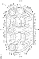
- the caliper 12 includes a caliper main body 15 (locking member) disposed across an outer circumferential side of the disc rotor 11 and fixed to the vehicle body side as shown in FIGS. 1 to 3 , and a pair of pistons 16 (pressing members) of the same shape accommodated in the caliper main body 15 as shown in FIGS. 2 to 4 , and a pair of pistons 17 (pressing members) of the same shape having smaller diameters than those of the pistons 16 and accommodated in the caliper main body 15.
- a line in the disc radial direction through the disc axis of the disc rotor 11 and a center of the caliper main body 15 in the disc rotation direction is referred to as a first radial reference line, and a direction in which the first radial reference line extends is referred to as a first reference line direction.
- the first radial reference line is perpendicular to the disc axis.
- the pair of pistons 16, which are common parts are provided in pairs on both sides of the disc rotor 11 in the disc axial direction to be aligned in the disc radial direction and the disc rotation direction.
- the pair of pistons 17, which are common parts are provided in pairs on both sides of the disc rotor 11 in the disc axial direction to be aligned in the disc radial direction and the disc rotation direction.
- one piston 16 and one piston 17 are provided to be aligned in the disc rotation direction with a predetermined distance therebetween on one side of the disc rotor 11 in the disc axial direction, and such a configuration is provided on both sides in the disc axial direction. Therefore, the caliper 12 is an opposed piston type four-pot caliper.
- the number of pistons may be at least one pair with the disc rotor 11 interposed therebetween and may also be three or four pairs in addition to the above-described two pairs. Further, the number of pistons may be different on both sides of the disc rotor 11 in the disc axial direction such as one and two or two and three.
- the caliper main body 15 includes a cylinder part 21 disposed on an outer side of the disc rotor 11 in the disc axial direction (on a side opposite to the wheel with respect to the disc rotor 11), and a cylinder part 22 disposed on an inner side (on the wheel side with respect to the disc rotor 11) of the disc rotor 11.
- the caliper main body 15 includes an end side connection part 23 (connection part) that connects one end portions of the cylinder part 21 and the cylinder part 22 in the disc rotation direction, an end side connection part 24 (connection part) that connects the other end portions of the cylinder part 21 and the cylinder part 22 in the disc rotation direction, and an intermediate connection part 25 that connects intermediate portions of the cylinder part 21 and the cylinder part 22 in the disc rotation direction.
- the end side connection part 23, the end side connection part 24, and the intermediate connection part 25 are all disposed to cross the disc rotor 11 on an outer side in the disc radial direction.
- the caliper main body 15 includes a pair of end side connection parts 23 and 24 that connect a pair of cylinder parts 21 and 22 across the disc rotor 11 at end portions of the pair of cylinder parts 21 and 22 in the disc rotation direction.
- the caliper main body 15 is a monoblock caliper in which the cylinder part 21, the cylinder part 22, the end side connection part 23, the end side connection part 24, and the intermediate connection part 25 are formed of an integral cast material. Therefore, the cylinder part 21 and the cylinder part 22 are integrally formed via the end side connection part 23, the end side connection part 24, and the intermediate connection part 25.
- the cylinder part 21 on the outer side is disposed to face a surface on an outer side of the disc rotor 11.
- the cylinder part 21 on the outer side includes a mounting boss part 34 disposed on the end side connection part 23 side which is one end in the disc rotation direction, and a mounting boss part 35 disposed on the end side connection part 24 side which is the other end in the disc rotation direction.
- the cylinder part 21 has a shape longer in the disc rotation direction to accommodate a plurality of pistons 16 and 17 which are aligned in the disc rotation direction.
- two cylinder bores 38 and 39 that accommodate the pistons 16 and 17 to be movable in the disc axial direction are formed to be aligned in the disc rotation direction.
- a large diameter cylinder bore 38 accommodating a large diameter piston 16 is disposed on the end side connection part 23 side in the disc rotation direction.
- a small diameter cylinder bore 39 accommodating a small diameter piston 17 is disposed on the end side connection part 24 side in the disc rotation direction.
- the cylinder bores 38 and 39 open to the disc rotor 11 side in the disc axial direction.
- a supply/discharge port 41 for supplying/discharging a brake fluid to the cylinder bores 38 and 39 is formed at a center position of the cylinder part 21 in the disc rotation direction.
- the supply/discharge port 41 is formed parallel to the first radial reference line.
- a mounting hole 44 and a mounting hole 45 are respectively formed to penetrate the mounting boss part 34 and the mounting boss part 35 in the disc radial direction. These mounting holes 44 and 45 are parallel to the first radial reference line. These mounting holes 44 and 45 are formed to be aligned with each other in the disc axial direction at equidistant positions from the center of the caliper main body 15 in the disc rotation direction.
- the caliper 12 is a so-called radial mount type in which the caliper 12 is fixed to the vehicle body side using mounting bolts (not shown) inserted into these mounting holes 44 and 45.
- a bleeder boss part 49 to which a bleeder plug 48 for bleeding air is attached is formed on the end side connection part 23.
- the caliper main body 15 is disposed on a rear side of the disc rotor 11 in a vehicle front-rear direction with the end side connection part 23 on which the bleeder boss part 49 is formed disposed on an upper side in a vertical direction. Therefore, when the vehicle travels forward, the disc rotor 11 moves upward from below in the vertical direction with respect to the caliper main body 15.
- the end side connection part 23 on one side on which the bleeder boss part 49 is disposed is disposed on a forward disc rotation exit side which is an exit side of the disc rotor 11 in a rotation direction R when the vehicle travels forward.
- the end side connection part 24 on the other side is disposed on a forward disc rotation entry side which is an entry side of the disc rotor 11 in the rotation direction R when the vehicle travels forward.
- the cylinder part 22 on the inner side is disposed to face a surface on an inner side of the disc rotor 11.
- the cylinder part 22 on the inner side has a shape longer in the disc rotation direction to accommodate the plurality of pistons 16 and 17 which are aligned in the disc rotation direction.
- two cylinder bores 58 and 59 that accommodate the pistons 16 and 17 to be movable in the disc axial direction are formed to be aligned in the disc rotation direction.
- a large diameter cylinder bore 58 accommodating a large diameter piston 16 is disposed on the end side connection part 23 side in the disc rotation direction.
- a small diameter cylinder bore 59 accommodating a small diameter piston 17 is disposed on the end side connection part 24 side in the disc rotation direction.
- the cylinder bores 58 and 59 open to the disc rotor 11 side in the disc axial direction.
- the supply/discharge port 41 of the cylinder part 21 on the outer side shown in FIG. 1 supplies/discharges the brake fluid to the cylinder bores 38 and 39 of the cylinder part 21 shown in FIG. 2 .
- the supply/discharge port 41 supplies/discharges the brake fluid also to the cylinder bores 58 and 59 of the cylinder part 22 shown in FIG. 3 .
- the cylinder part 21 shown in FIGS. 1 and 2 and the cylinder part 22 shown in FIGS. 1 and 3 are disposed to face in the disc axial direction while positions thereof in the disc rotation direction and the disc radial direction are aligned to be superimposed on each other.
- the cylinder bore 58 is formed coaxially with the cylinder bore 38, and the cylinder bore 59 is formed coaxially with the cylinder bore 39.
- the end side connection part 23 includes a pad support part 32A and a pad support part 33B on the end side connection part 24 side in the disc rotation direction.
- the pad support part 32A is disposed on the outer side of the disc rotor 11, and the pad support part 33B is disposed on the inner side of the disc rotor 11.
- the end side connection part 24 includes a pad support part 32B and a pad support part 33A on the end side connection part 23 side in the disc rotation direction.
- the pad support part 33A is disposed on the outer side of the disc rotor 11, and the pad support part 32B is disposed on the inner side of the disc rotor 11.
- the end side connection part 23 includes the pad support parts 32A and 33B on both sides of the disc rotor 11 in the disc axial direction.
- the end side connection part 24 includes the pad support parts 32B and 33A on both sides of the disc rotor 11 in the disc axial direction.
- the pad support parts 32A, 33B, 32B, and 33A are provided in the end side connection parts 23 and 24.
- the pad support parts 32A and 33B are disposed on the forward disc rotation exit side.
- the pad support parts 32B and 33A are disposed on the forward disc rotation entry side.
- the pad support part 32A and the pad support part 33B shown in FIGS. 1 and 4 are disposed to face in the disc axial direction while positions thereof in the disc rotation direction and the disc radial direction are aligned to be superimposed on each other. Also, the pad support part 33A and the pad support part 32B are disposed to face in the disc axial direction while positions thereof in the disc rotation direction and the disc radial direction are aligned to be superimposed on each other. As shown in FIG. 4 , the disc rotor 11 is disposed between: the pad support parts 32A and 33A; and the pad support parts 32B and 33B.
- the pair of end side connection parts 23 and 24 connect the pair of cylinder parts 21 and 22 across the disc rotor 11 at end portions of the pair of cylinder parts 21 and 22 in the disc rotation direction.
- a pad disposition space 61 that opens to both sides in the disc radial direction is formed substantially at a center of the caliper main body 15 surrounded by the cylinder parts 21 and 22 and the pad support parts 32A, 32B, 33A, and 33B.
- the entire pad disposition space 61 opens to an inner side in the disc radial direction.
- the intermediate connection part 25 is provided at a center position of the caliper main body 15 in the disc rotation direction.
- the intermediate connection part 25 is provided across the pad disposition space 61 in the disc axial direction on the outer side in the disc radial direction.
- the outer side in the disc radial direction of the pad disposition space 61 opens at a portion between the pad support parts 32Aand 33B on one side in the disc rotation direction and the intermediate connection part 25, and at a portion between the pad support parts 33A and 32B on the opposite side in the disc rotation direction and the intermediate connection part 25.
- the cylinder bores 38, 39, 58, and 59 shown in FIGS. 2 and 3 open to the pad disposition space 61 shown in FIG. 4 .
- the disc rotor 11 traverses a center position in the disc axial direction of the pad disposition space 61 in the disc rotation direction.
- the cylinder part 21, the cylinder part 22, the end side connection part 23, the end side connection part 24, and the intermediate connection part 25 shown in FIG. 1 are integrally formed by casting except for bottom portions of the cylinder bores 58 and 59 of the cylinder part 22 shown in FIG. 3 .
- cutting work is performed on inner surfaces of the cylinder bores 38, 39, 58, and 59 via openings formed by casting at the bottom portions of the two cylinder bores 58 and 59 of the cylinder part 22.
- the caliper main body 15 is formed by joining a separate closing member to the openings at the bottom portions of the cylinder bores 58 and 59 of the cylinder part 22 by friction stir welding to close the openings and form the bottom portions.
- this may also be achieved by integrally forming the whole of the cylinder part 21, the cylinder part 22, the end side connection part 23, the end side connection part 24, and the intermediate connection part 25 by casting, and performing cutting work on the inner surfaces of the cylinder bores 38, 39, 58, and 59 via the pad disposition space 61 between the cylinder parts 21 and 22.
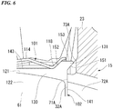
- a torque receiving surface 71A facing the pad disposition space 61 side, a rotor facing surface 72A facing the disc rotor 11 side, and a flat surface portion 73 A facing outward in the disc radial direction are formed on the outer pad support part 32A of the end side connection part 23 on the forward disc rotation exit side.
- the torque receiving surface 71A is a flat surface extending parallel to the first radial reference line.
- the torque receiving surface 71A also extends parallel to the disc axis.
- the rotor facing surface 72A extends perpendicular to the disc axis.
- the flat surface portion 73A is a flat surface extending parallel to the disc axis.
- the flat surface portion 73A in the first reference line direction, is inclined to become further away from the first radial reference line outward in the disc radial direction.
- the flat surface portion 73 A is inclined in a direction away from a center of the caliper 12 in a rotor rotation direction outward in the disc radial direction.
- the flat surface portion 73A and the torque receiving surface 71A form an obtuse angle.
- the flat surface portion 73A and the torque receiving surface 71A are not limited to having an obtuse angle and may have an acute angle.
- a torque receiving surface 81A facing the pad disposition space 61 side, a rotor facing surface 82A facing the disc rotor 11 side, and a flat surface portion 83 A facing outward in the disc radial direction are formed on the outer pad support part 33A of the end side connection part 24 on the forward disc rotation entry side.
- the torque receiving surface 81A is a flat surface extending parallel to the first radial reference line.
- the torque receiving surface 81A also extends parallel to the disc axis.
- the rotor facing surface 82A extends perpendicular to the disc axis. As shown in FIG. 4 , the rotor facing surface 82A is disposed on the same plane as the rotor facing surface 72A.
- the flat surface portion 83A is a flat surface extending parallel to the disc axis. As shown in FIG. 5 , in the first reference line direction, the flat surface portion 83 A is inclined to become further away from the first radial reference line outward in the disc radial direction. The flat surface portion 83A is inclined in a direction away from the center of the caliper 12 in the rotor rotation direction outward in the disc radial direction. The flat surface portion 83A and the torque receiving surface 81A form an obtuse angle. The angle formed by the flat surface portion 83A and the torque receiving surface 81A is equivalent to an angle formed by the flat surface portion 73A and the torque receiving surface 71A.
- the flat surface portion 83 A and the torque receiving surface 81A are not limited to having an obtuse angle and may have an acute angle.
- a line connecting a boundary position between the flat surface portion 73 A and the torque receiving surface 71A to a boundary position between the flat surface portion 83A and the torque receiving surface 81A is parallel to a line connecting the torque receiving surface 71A and the torque receiving surface 81A perpendicularly to each other. Therefore, the boundary position between the flat surface portion 73 A and the torque receiving surface 71A is aligned with the boundary position between the flat surface portion 83A and the torque receiving surface 81A in the disc radial direction.
- an inner end position of the flat surface portion 73A in the disc radial direction and an inner end position of the flat surface portion 83A in the disc radial direction are aligned in the disc radial direction.
- a length of a line connecting the inner end position of the flat surface portion 73A in the disc radial direction to the central axis of the disc rotor 11 is equivalent to a length of a line connecting the inner end position of the flat surface portion 83A in the disc radial direction to the central axis of the disc rotor 11.
- a torque receiving surface 81B facing the pad disposition space 61 side and a rotor facing surface 82B facing the disc rotor 11 are formed in the inner pad support part 33B of the end side connection part 23 on the forward disc rotation exit side.
- a flat surface portion 83B facing outward in the disc radial direction is formed on the pad support part 33B.
- the torque receiving surface 81B shown in FIG. 4 is a flat surface extending parallel to the first radial reference line.
- the torque receiving surface 81B also extends parallel to the disc axis.
- the torque receiving surface 81B is disposed on the same plane as the torque receiving surface 71A.
- the rotor facing surface 82B extends perpendicular to the disc axis.
- the flat surface portion 83B shown in FIG. 1 is a flat surface extending parallel to the disc axis. As shown in FIG. 7 , in the first reference line direction, the flat surface portion 83B is inclined to become further away from the first radial reference line outward in the disc radial direction.
- the flat surface portion 83B is inclined in a direction away from the center of the caliper 12 in the rotor rotation direction outward in the disc radial direction.
- the flat surface portion 83B is disposed on the same plane as the flat surface portion 73A.
- the flat surface portion 83B and the torque receiving surface 81B that is shown in FIG. 4 form an obtuse angle.
- the angle formed by the flat surface portion 83B and the torque receiving surface 81B is equivalent to an angle formed by the flat surface portion 73A and the torque receiving surface 71A.
- the flat surface portion 83B and the torque receiving surface 81B are not limited to having an obtuse angle and may have an acute angle.
- the torque receiving surface 71A and the torque receiving surface 81A are parallel to each other.
- the torque receiving surface 71B and the torque receiving surface 81B are parallel to each other.
- a distance between the torque receiving surface 71A and the torque receiving surface 81A is equivalent to a distance between the torque receiving surface 71B and the torque receiving surface 81B.
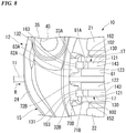
- a torque receiving surface 71B facing the pad disposition space 61 side and a rotor facing surface 72B facing the disc rotor 11 are formed in the inner pad support part 32B of the end side connection part 24 on the forward disc rotation entry side.
- a flat surface portion 73B facing outward in the disc radial direction is formed on the pad support part 32B.
- the torque receiving surface 71B shown in FIG. 4 is a flat surface extending parallel to the first radial reference line.
- the torque receiving surface 71B also extends parallel to the disc axis.
- the torque receiving surface 71B is disposed on the same plane as the torque receiving surface 81A.
- the rotor facing surface 72B extends perpendicular to the disc axis.
- the rotor facing surface 72B is disposed on the same plane as the rotor facing surface 82B.
- the flat surface portion 73B shown in FIGS. 1 and 8 is a flat surface extending parallel to the disc axis. In the first reference line direction, the flat surface portion 73B is inclined to become further away from the first radial reference line outward in the disc radial direction.
- the flat surface portion 73B is inclined in a direction away from the center of the caliper 12 in the rotor rotation direction outward in the disc radial direction.
- the flat surface portion 73B is disposed on the same plane as the flat surface portion 83A.
- the flat surface portion 73B and the torque receiving surface 71B form an obtuse angle.
- the angle formed by the flat surface portion 73B and the torque receiving surface 71B is equivalent to an angle formed by the flat surface portion 73A and the torque receiving surface 71A.
- the flat surface portion 73B and the torque receiving surface 71B are not limited to having an obtuse angle and may form an acute angle.
- a line connecting a boundary position between the flat surface portion 73B and the torque receiving surface 71B to a boundary position between the flat surface portion 83B and the torque receiving surface 81B is parallel to a line connecting the torque receiving surface 71B and the torque receiving surface 81B perpendicularly to each other.
- the boundary position between the flat surface portion 73B and the torque receiving surface 71B is aligned with the boundary position between the flat surface portion 83B and the torque receiving surface 81B in the disc radial direction.
- These boundary positions are also aligned with the boundary position between the flat surface portion 73A and the torque receiving surface 71A and the boundary position between the flat surface portion 83A and the torque receiving surface 81A in the disc radial direction.
- an inner end position of the flat surface portion 73B in the disc radial direction and an inner end position of the flat surface portion 83B in the disc radial direction are aligned in the disc radial direction.
- a length of a line connecting the inner end position of the flat surface portion 73B in the disc radial direction to the central axis of the disc rotor 11 is equivalent to a length of a line connecting the inner end position of the flat surface portion 83B in the disc radial direction and the central axis of the disc rotor 11.
- These inner end positions are also aligned in the disc radial direction with the inner end position of the flat surface portion 73A in the disc radial direction and the inner end position of the flat surface portion 83A in the disc radial direction.
- an engaging recessed part 91 and an engaging recessed part 92 having different widths in the disc axial direction are formed in the intermediate connection part 25 on the forward disc rotation exit side and the forward disc rotation entry side.
- the engaging recessed part 91 on the forward disc rotation exit side is recessed from a wall surface of the intermediate connection part 25 on the forward disc rotation exit side toward the forward disc rotation entry side.
- the engaging recessed part 92 on the forward disc rotation entry side is recessed from a wall surface of the intermediate connection part 25 on the forward disc rotation entry side toward the forward disc rotation exit side.
- a width of the engaging recessed part 91 on the forward disc rotation exit side in the disc axial direction is larger than that of the engaging recessed part 92 on the forward disc rotation entry side.
- a pad spring 101 is attached to the caliper main body 15 by being locked to the engaging recessed parts 91 and 92 of the intermediate connection part 25.
- the caliper main body 15 supports a pair of friction pads 102 and 102 having the same shape that are biased by the pad spring 101. These friction pads 102 are disposed to face the disc rotor 11.
- One friction pad 102 is disposed between the cylinder part 21 on the outer side and the disc rotor 11, and the other friction pad 102 is disposed between the cylinder part 22 on the inner side and the disc rotor 11.
- the pad spring 101 is formed by press-forming a plate having a constant plate thickness by punching and bending the plate.
- the pad spring 101 includes a base plate 111, an engaging plate part 112, and an engaging plate part 113 shown in FIG. 5 , and a pair of extended plate parts 114 and 115 and a pair of extended plate parts 116 and 117 shown in FIG. 1 .
- the base plate 111 shown in FIG. 5 is disposed between the intermediate connection part 25 and the pair of friction pads 102 and is in contact with the intermediate connection part 25.
- the engaging plate part 112 extends outward in the disc radial direction from an end edge portion of the base plate 111 on the forward disc rotation exit side and engages with the engaging recessed part 91 of the intermediate connection part 25.
- the engaging plate part 113 extends outward in the disc radial direction from an end edge portion of the base plate 111 on the forward disc rotation entry side and engages with the engaging recessed part 92 of the intermediate connection part 25. Thereby, the engaging plate parts 112 and 113 sandwich the intermediate connection part 25. As a result, the pad spring 101 is attached to the caliper main body 15.
- the engaging plate part 112 on the forward disc rotation exit side is wider than the engaging plate part 113 on the forward disc rotation entry side in the disc axial direction.
- the engaging plate part 112 is configured such that its proper engagement with the engaging recessed parts 92, which has a narrower width between the engaging recessed parts 91 and 92 in the disc axial direction, is inhibited. Thereby, erroneous assembly in which the pad spring 101 is attached by reversing in the disc rotation direction is restricted.
- the pair of extended plate parts 114 and 115 on the forward disc rotation exit side extend from the end edge portion of the base plate 111 on the forward disc rotation exit side to the forward disc rotation exit side.
- a V-shaped bent part 118 protruding inward in the disc radial direction on the forward disc rotation exit side is formed on the extended plate part 114 on the outer side.
- a V-shaped bent part 119 protruding inward in the disc radial direction on the forward disc rotation exit side is also formed on the extended plate part 115 on the inner side shown in FIG. 1 .
- the extended plate parts 114 and 115 have a mirror-symmetrical shape.
- the extended plate parts 114 and 115 are disposed on both sides of the engaging plate part 112 in the disc axial direction.
- the pair of extended plate parts 116 and 117 on the forward disc rotation entry side extend from the end edge portion of the base plate 111 on the forward disc rotation entry side to the forward disc rotation entry side.
- the extended plate part 116 on the outer side has a stepped shape in which a predetermined range on the forward disc rotation entry side is positioned on an outer side in the disc radial direction with respect to a predetermined range on the forward disc rotation exit side.
- the extended plate part 117 on the inner side shown in FIG. 1 also has a similar stepped shape and has a mirror-symmetrical shape with respect to the extended plate part 116.
- the extended plate parts 116 and 117 are disposed on both sides of the engaging plate part 113 in the disc axial direction.
- the extended plate parts 114 and 116 on the outer side come into contact with the outer friction pad 102 and press it inward in the disc radial direction.
- the extended plate part 114 on the forward disc rotation exit side comes into contact with the outer friction pad 102 at the bent part 118 and presses the friction pad 102 also to the forward disc rotation exit side.
- the extended plate parts 115 and 117 on the inner side shown in FIG. 1 come into contact with the inner friction pad 102 and press it inward in the disc radial direction.
- the extended plate part 115 on the forward disc rotation exit side comes into contact with the inner friction pad 102 at the bent part 119 and presses the friction pad 102 also to the forward disc rotation exit side as well.
- the pair of friction pads 102 are common parts having the same shape. As shown in FIG. 5 , the friction pads 102 each include a back plate 121 which is long in the disc rotation direction, and lining materials 122 and 123 affixed to two places spaced apart from each other in a longitudinal direction on a surface on one side in the thickness direction of the back plate 121. The friction pad 102 is supported by the caliper 12 at the back plate 121. The friction pad 102 comes into contact with the disc rotor 11 via the lining materials 122 and 123 and applies a braking force to the vehicle.
- the back plate 121 has a constant plate thickness.
- the back plate 121 includes a main plate part 130 to which the lining materials 122 and 123 are affixed, and a pair of an extended part 131 and an extended part 132 which extend to both outer sides in the disc rotation direction from both end portion sides in the disc rotation direction and an outer side in the disc radial direction of the main plate part 130.
- the main plate part 130 has substantially a rectangular shape that is long in the disc rotation direction.
- the extended part 131 and the extended part 132 extend in a direction inclined with respect to the longitudinal direction of the main plate part 130 from the both end portion sides of the main plate part 130 in the disc rotation direction which are on both sides thereof in the longitudinal direction.
- the longitudinal direction of the main plate part 130 is the longitudinal direction of the back plate 121 and the longitudinal direction of the friction pad 102. Therefore, the pair of extended parts 131 and 132 which extend in a direction inclined with respect to the longitudinal direction of the friction pad 102 are formed in the back plate 121 on both end portion sides in the disc rotation direction and an outer side in the disc radial direction.
- the main plate part 130 has a mirror-symmetrical outer shape.
- shapes of the extended part 131 and the extended part 132 are mirror symmetrical.
- the extended part 131 on one side extends in a direction away from the main plate part 130 in the longitudinal direction of the main plate part 130 from one end portion side in the disc rotation direction and an outer side in the disc radial direction of the main plate part 130.
- the extended part 131 is inclined such that it is positioned further outward in the disc radial direction in the first reference line direction toward an extended distal end side.
- the extended part 132 on the other side extends in a direction away from the main plate part 130 in the longitudinal direction of the main plate part 130 from the other end portion side in the disc rotation direction and an outer side in the disc radial direction of the main plate part 130.
- the extended part 132 is inclined such that it is positioned further outward in the disc radial direction in the first reference line direction toward an extended distal end side.
- the main plate part 130 includes a side surface portion 141 which is a flat surface extending perpendicular to the longitudinal direction of the main plate part 130 on one side thereof in the longitudinal direction which is a base position of the extended part 131.
- the main plate part 130 includes a side surface portion 142 which is a flat surface extending perpendicular to the longitudinal direction of the main plate part 130 on the other side thereof in the longitudinal direction which is a base position of the extended part 132.
- the main plate part 130 includes an outer surface portion 143 which is a flat surface extending perpendicular to the first radial reference line on the outer side in the disc radial direction.
- the side surface portions 141 and 142 and the outer surface portion 143 are all flat surfaces extending in a plate thickness direction of the back plate 121.
- the side surface portions 141 and 142 are parallel to each other.
- the side surface portions 141 and 142 are perpendicular to the outer surface portion 143.
- the extended part 131 extends from between the side surface portion 141 and the outer surface portion 143.
- the extended part 131 has a rhombic shape when the back plate 121 is viewed from a plate thickness direction.
- the extended part 131 includes a surface portion 151 (facing surface portion) on an inner side in the disc radial direction, a surface portion 152 on an outer side in the disc radial direction and an inner side in the disc rotation direction, and a surface portion 153 on an outer side in the disc radial direction and an outer side in the disc rotation direction.
- the surface portions 151, 152, and 153 are all flat surfaces extending in the plate thickness direction of the back plate 121.
- the surface portions 151, 152, and 153 extend in the disc axial direction.
- the surface portion 151 extends outward in the disc radial direction and outward in the disc rotation direction obliquely with respect to the longitudinal direction of the friction pad 102 and the first reference line direction from an end edge portion of the side surface portion 141 on the outer side in the disc radial direction.
- the surface portion 151 and the side surface portion 141 form an obtuse angle.
- the angle formed by the surface portion 151 and the side surface portion 141 is equivalent to an angle formed by the flat surface portion 73 A of the pad support part 32A and the torque receiving surface 71A.
- the surface portion 152 extends outward in the disc radial direction and outward in the disc rotation direction obliquely with respect to the longitudinal direction of the friction pad 102 and the first reference line direction from an end edge portion of the outer surface portion 143 on the side surface portion 141 side in the disc rotation direction.
- the surface portion 152 and the outer surface portion 143 form an obtuse angle.
- the surface portion 152 extends parallel to the surface portion 151.
- the surface portion 153 connects an end edge portion of the surface portion 151 on a side opposite to the side surface portion 141 to an end edge portion of the surface portion 152 on a side opposite to the outer surface portion 143.
- the surface portion 153 extends parallel to the outer surface portion 143.
- the surface portion 151 and the surface portion 153 form an acute angle.
- the extended part 132 extends from between the side surface portion 142 and the outer surface portion 143.
- the extended part 132 has a rhombic shape when the back plate 121 is viewed from the plate thickness direction.
- the extended part 132 includes a surface portion 161 (facing surface portion) on an inner side in the disc radial direction, a surface portion 162 on an outer side in the disc radial direction and an inner side in the disc rotation direction, and a surface portion 163 on an outer side in the disc radial direction and an outer side in the disc rotation direction.
- the surface portions 161, 162, and 163 are all flat surfaces extending in the plate thickness direction of the back plate 121.
- the surface portions 161, 162, and 163 extend in the disc axial direction.
- the surface portion 161 extends outward in the disc radial direction and outward in the disc rotation direction obliquely with respect to the longitudinal direction of the friction pad 102 and the first reference line direction from an end edge portion of the side surface portion 142 on the outer side in the disc radial direction.
- the surface portion 161 and the side surface portion 142 form an obtuse angle.
- An angle formed by the surface portion 161 and the side surface portion 142 is equivalent to the angle formed by the surface portion 151 and the side surface portion 141.
- the surface portion 162 extends outward in the disc radial direction and outward in the disc rotation direction obliquely with respect to the longitudinal direction of the friction pad 102 and the first reference line direction from an end edge portion of the outer surface portion 143 on the side surface portion 142 side in the disc rotation direction.
- the surface portion 162 and the outer surface portion 143 form an obtuse angle.
- the angle formed by the surface portion 162 and the outer surface portion 143 is equivalent to an angle formed by the surface portion 152 and the outer surface portion 143.
- the surface portion 162 extends parallel to the surface portion 161.
- the surface portion 163 connects an end edge portion of the surface portion 161 on a side opposite to the side surface portion 142 to an end edge portion of the surface portion 162 on a side opposite to the outer surface portion 143.
- the surface portion 163 extends parallel to the outer surface portion 143.
- the surface portion 161 and the surface portion 163 form an acute angle.
- the surface portion 163 is disposed on the same plane as the surface portion 153.
- a line connecting a boundary position between the surface portion 161 and the side surface portion 142 to a boundary position between the surface portion 151 and the side surface portion 141 is parallel to a line connecting the side surface portion 141 and the side surface portion 142 perpendicularly to each other.
- a distance between the side surface portion 141 and the side surface portion 142 is smaller than the distance between the torque receiving surface 71A and the torque receiving surface 81A.
- a maximum distance between the surface portion 151 and the surface portion 161 is larger than the distance between the torque receiving surface 71A and the torque receiving surface 81A.
- the distance between the side surface portion 141 and the side surface portion 142 is smaller than the distance between the torque receiving surface 71B and the torque receiving surface 81B.
- the maximum distance between the surface portion 151 and the surface portion 161 is larger than the distance between the torque receiving surface 71B and the torque receiving surface 81B.
- the extended part 131 is supported by the pad support part 32A on the forward disc rotation exit side and the extended part 132 is supported by the pad support part 33A on the forward disc rotation entry side in a posture of the friction pad 102 in which the lining materials 122 and 123 are disposed on an inner side with respect to the back plate 121 and the extended parts 131 and 132 are disposed on the outer side in the disc radial direction.
- the extended part 131 disposed on the forward disc rotation exit side comes into contact with the bent part 118 of the extended plate part 114 of the pad spring 101 at the surface portion 152 and is pressed inward in the disc radial direction and toward the forward disc rotation exit side by the bent part 118.
- the extended part 131 comes into contact with the flat surface portion 73 A of the pad support part 32A at the surface portion 151.
- the extended part 132 on the forward disc rotation entry side comes into contact with the extended plate part 116 of the pad spring 101 at the surface portion 163 and is pressed inward in the disc radial direction by the extended plate part 116.
- the extended part 132 comes into contact with the flat surface portion 83 A of the pad support part 33A at the surface portion 161.
- the biasing force of the pad spring 101 brings the side surface portion 141 of the main plate part 130 into direct contact with the facing torque receiving surface 71A on the outer side and the forward disc rotation exit side by surface contact, brings the surface portion 151 of the extended part 131 into direct contact with the facing flat surface portion 73A on the outer side and the forward disc rotation exit side by surface contact, and brings the surface portion 161 of the extended part 132 into direct contact with the facing flat surface portion 83A on the outer side and the forward disc rotation entry side by surface contact.
- the outer pad support part 32A of the caliper main body 15 includes the flat surface portion 73A that extends in a direction in which the extended part 131 of the outer friction pad 102 extends. In this state, the extended part 131 of the outer friction pad 102 is locked to the outer pad support part 32A. Also, in this state, the outer pad support part 33A of the caliper main body 15 includes the flat surface portion 83A that extends in a direction in which the extended part 132 of the outer friction pad 102 extends. In this state, the extended part 132 of the outer friction pad 102 is locked to the outer pad support part 33A.
- the outer friction pad 102 brings the side surface portion 141 of the main plate part 130 into contact with the torque receiving surface 71A, and causes the side surface portion 142 of the main plate part 130 to face the torque receiving surface 81A with a slight gap therebetween. Further, in this state, the extended parts 131 and 132 of the outer friction pad 102 are disposed on an outer side in the disc radial direction with respect to an outermost circumference of the disc rotor 11. Also, in this state, the torque receiving surfaces 71A and 81A face in a direction in which the friction pad 102 is disposed.
- the extended part 131 is supported by the pad support part 32B on the forward disc rotation entry side and the extended part 132 is supported by the pad support part 33B on the forward disc rotation exit side in a posture of the friction pad 102 in which the lining materials 122 and 123 are disposed on the outer side of the back plate 121 and the extended parts 131 and 132 are disposed on the outer side in the disc radial direction.
- the extended part 132 disposed on the forward disc rotation exit side comes into contact with the bent part 119 of the extended plate part 115 of the pad spring 101 at the surface portion 162 and is pressed inward in the disc radial direction and toward the forward disc rotation exit side by the bent part 119.
- the extended part 132 comes into contact with the flat surface portion 83B of the pad support part 33B at the surface portion 161.
- the extended part 131 on the forward disc rotation entry side comes into contact with the extended plate part 117 of the pad spring 101 at the surface portion 153 and is pressed inward in the disc radial direction by the extended plate part 117.
- the extended part 131 comes into contact with the flat surface portion 73B of the pad support part 32B at the surface portion 151.
- the biasing force of the pad spring 101 brings the side surface portion 142 of the main plate part 130 into direct contact with the facing torque receiving surface 81B on the inner side and the forward disc rotation exit side by surface contact, brings the surface portion 161 of the extended part 132 into direct contact with the facing flat surface portion 83B on the inner side and the forward disc rotation exit side by surface contact, and brings the surface portion 151 of the extended part 131 into direct contact with the facing flat surface portion 73B on the inner side and the forward disc rotation entry side by surface contact.
- the inner pad support part 32B of the caliper main body 15 includes the flat surface portion 73B that extends in a direction in which the extended part 131 of the inner friction pad 102 extends. In this state, the extended part 131 of the inner friction pad 102 is locked to the inner pad support part 32B. Also, in this state, the inner pad support part 33B of the caliper main body 15 includes the flat surface portion 83B that extends in a direction in which the extended part 132 of the inner friction pad 102 extends. In this state, the extended part 132 of the inner friction pad 102 is locked to the inner pad support part 33B.
- the inner friction pad 102 brings the side surface portion 142 of the main plate part 130 into contact with the torque receiving surface 81B, and causes the side surface portion 141 of the main plate part 130 to face the torque receiving surface 71B with a slight gap therebetween. Further, in this state, the extended parts 131 and 132 of the inner friction pad 102 are disposed on an outer side in the disc radial direction with respect to the outermost circumference of the disc rotor 11. Also, in this state, the torque receiving surfaces 71B and 81B face in a direction in which the friction pad 102 is disposed. As described above, the pair of friction pads 102 are locked to one caliper main body 15.
- the outer friction pad 102 shown in FIG. 5 is supported by the outer pad support parts 32Aand 33A of the caliper main body 15 and moves in the disc axial direction. At that time, the pad support parts 32A and 33Alock the extended parts 131 and 132 of the outer friction pad 102 with the flat surface portions 73A and 83A disposed in a V shape on both sides in the disc rotation direction.
- the inner friction pad 102 shown in FIG. 1 is supported by the inner pad support parts 32B and 33B of the caliper main body 15 and moves in the disc axial direction. At that time, the pad support parts 32B and 33B lock the extended parts 131 and 132 of the inner friction pad 102 with the flat surface portions 73B and 83B disposed in a V shape on both sides in the disc rotation direction.
- the caliper 12 has a so-called pad pin-less structure in which the pair of friction pads 102 are directly supported by the caliper main body 15 without having a pad pin that supports the pair of friction pads 102.
- the pad support parts 32A, 33A, 32B, and 33B support the pair of friction pads 102 provided to face each other across the disc rotor 11 to be able to press against the disc rotor 11.
- the two pistons 16 and 17 provided in the cylinder part 22 on the inner side press the inner friction pad 102 provided between the cylinder part 22 and the disc rotor 11 so that the lining materials 122 and 123 thereof are pressed against the disc rotor 11. Thereby, a braking force is generated in the vehicle.
- the pistons 16 and 17 on the outer side press the outer friction pad 102 against the disc rotor 11, and the pistons 16 and 17 on the inner side press the inner friction pad 102 against the disc rotor 11.
- the pair of friction pads 102 are locked to the caliper main body 15 so that inward movement in the disc radial direction and movement in the disc rotation direction are restricted by the pad support parts 32A, 33A, 32B, and 33B, and move in the disc axial direction.
- the outer friction pad 102 shown in FIG. 5 is locked to the outer pad support parts 32Aand 33A at the extended parts 131 and 132 and moves.
- the extended part 131 slides on the flat surface portion 73A of the pad support part 32A by the surface portion 151
- the extended part 132 slides on the flat surface portion 83 A of the pad support part 33A by the surface portion 161.
- the inner friction pad 102 shown in FIG. 1 is supported by the inner pad support parts 32B and 33B at the extended parts 131 and 132 and moves.
- the extended part 132 slides on the flat surface portion 83B of the pad support part 33B by the surface portion 161, and the extended part 131 slides on the flat surface portion 73B of the pad support part 32B by the surface portion 151.
- the caliper main body 15 including the pad support parts 32A, 33A, 32B, and 33B locks the friction pad 102 to be movable in the disc axial direction.
- both the friction pads 102 come into contact with the disc rotor 11 via the lining materials 122 and 123 and move to the forward disc rotation exit side. Then, as shown in FIG. 4 , the outer friction pad 102 comes into contact with the torque receiving surface 71A of the pad support part 32A, which is on the forward disc rotation exit side, at the side surface portion 141 of the back plate 121, and the inner friction pad 102 comes into contact with the torque receiving surface 81B of the pad support part 33B, which is on the forward disc rotation exit side, at the side surface portion 142 of the back plate 121. Thereby, the caliper main body 15 receives a braking torque mainly at the pad support parts 32A and 33B.
- both the friction pads 102 come into contact with the disc rotor 11 via the lining materials 122 and 123 and move to a rearward disc rotation exit side. Then, the outer friction pad 102 comes into contact with the torque receiving surface 81A of the pad support part 33A, which is on the rearward disc rotation exit side, at the side surface portion 142 of the back plate 121, and the inner friction pad 102 comes into contact with the torque receiving surface 71B of the pad support part 32B, which is on the rearward disc rotation exit side, at the side surface portion 141 of the back plate 121. Thereby, the caliper main body 15 receives the braking torque mainly at the pad support parts 32B and 33A.
- Patent Document 1 described above describes a disc brake in which an extended part extending in a longitudinal direction of a friction pad is formed on both end portion sides in the disc rotation direction and an outer side in the disc radial direction of the friction pad, and the extended part is supported by a caliper main body.
- a retainer as a countermeasure against wear of the caliper main body, is interposed between the extended part of the friction pad and the caliper main body. Therefore, a space for disposing the retainer is required, and this causes an increase in size of the caliper main body, resulting in an increase in costs. Also, the number of parts increases due to the retainer, resulting in an increase in costs.
- the extended parts 131 and 132 extending in a direction inclined with respect to the longitudinal direction of the friction pad 102 are formed on both end portion sides in the disc rotation direction and an outer side in the disc radial direction of the back plate 121 of the friction pad 102.
- the caliper main body 15 that locks the friction pad 102 to be movable in the disc axial direction includes the pad support part 32A having the flat surface portion 73A that extends in a direction in which the extended part 131 of the outer friction pad 102 extends, the pad support part 33A having the flat surface portion 83Athat extends in a direction in which the extended part 132 of the outer friction pad 102 extends, the pad support part 32B having the flat surface portion 73B that extends in a direction in which the extended part 131 of the inner friction pad 102 extends, and the pad support part 33B having the flat surface portion 83B that extends in a direction in which the extended part 132 of the inner friction pad 102 extends.
- the extended part 131 of the outer friction pad 102 is brought into contact with the flat surface portion 73A and locked to the pad support part 32A, the extended part 132 of the outer friction pad 102 is brought into contact with the flat surface portion 83 A and locked to the pad support part 33A, the extended part 131 of the inner friction pad 102 is brought into contact with the flat surface portion 73B and locked to the pad support part 32B, and the extended part 132 of the inner friction pad 102 is brought into contact with the flat surface portion 83B and locked to the pad support part 33B.
- contact lengths between the extended parts 131 and 132 of the outer friction pad 102 and the flat surface portions 73A and 83 A can be increased without increasing lengths of the extended parts 131 and 132 of the outer friction pad 102 and the outer pad support parts 32A and 33A in the disc rotation direction, and thereby a contact area can be increased.
- a contact length between the extended parts 131 and 132 of the inner friction pad 102 and the flat surface portions 73B and 83B can be increased without increasing lengths of the extended parts 131 and 132 of the inner friction pad 102 and the inner pad support parts 32B and 33B in the disc rotation direction, and thereby a contact area can be increased.
- a vibration load of the friction pad 102 received by the caliper main body 15 can be dispersed. Therefore, wear of the caliper main body 15 can be suppressed without interposing a retainer as a countermeasure against wear between the extended parts 131 and 132 of the pair of friction pads 102 and the pad support parts 32A, 32B, 33A, and 33B.
- a structure can be made such that the flat surface portion 73 A of the outer pad support part 32A is brought into direct contact with the facing surface portion 151 of the extended part 131 of the outer friction pad 102, the flat surface portion 83A of the outer pad support part 33A is brought into direct contact with the facing surface portion 161 of the extended part 132 of the outer friction pad 102, the flat surface portion 73B of the inner pad support part 32B is brought into direct contact with the facing surface portion 151 of the extended part 131 of the inner friction pad 102, and the flat surface portion 83B of the inner pad support part 33B is brought into direct contact with the facing surface portion 161 of the extended part 132 of the inner friction pad 102.
- the structure is made such that a retainer as a countermeasure against wear is not interposed between the extended parts 131 and 132 of the pair of friction pads 102 and the pad support parts 32A, 33A, 32B, and 33B, and thus the number of parts can be reduced. Therefore, costs of parts and assembly man-hours can be reduced. In addition, it is not necessary to secure a space for disposing the retainer, and thus a degree of freedom in design increases.
- a vibration load of the friction pad 102 received by the caliper main body 15 can be dispersed, wear of the caliper main body 15 can be suppressed without increasing a load of the pad spring 101. Therefore, dragging of the friction pad 102 that occurs when the load of the pad spring 101 is large can be suppressed.
- the extended parts 131 and 132 of the friction pads 102 on both the outer side and inner side are disposed on an outer side in the disc radial direction with respect to the outermost circumference of the disc rotor 11. Therefore, the flat surface portions 73A, 83A, 73B, and 83B of the pad support parts 32A, 33A, 32B, and 33B supporting the extended parts 131 and 132 can be easily made as surfaces exposed to the outside on the outer side in the disc radial direction. Therefore, the flat surface portions 73A, 83A, 73B, and 83B can be formed by casting without a core. Therefore, the flat surface portions 73A, 83A, 73B, and 83B can be formed without using or processing a core, and thus manufacturing costs can be reduced.
- the caliper main body 15 that locks the pair of friction pads 102 includes the pair of cylinder parts 21 and 22 in which the pistons 16 and 17 as pressing members are accommodated and disposed to face each other, and the pair of end side connection parts 23 and 24 that connect the pair of cylinder parts 21 and 22 across the disc rotor 11 at the end portions of the pair of cylinder parts 21 and 22 in the disc rotation direction.
- the pad support parts 32A and 33B are provided at the end side connection part 23 on one side, and the pad support parts 32B and 33A are provided at the end side connection part 24 on the other side. Therefore, a size of the caliper main body 15 in the disc rotation direction is highly effectively reduced.
- the outer pad support part 33A on the forward disc rotation entry side and the inner pad support part 32B on the forward disc rotation entry side in the caliper main body 15 may be connected in the disc axial direction on the outer side in the disc radial direction. That is, a support part connecting part 181 that connects the pad support part 33 A and the pad support part 32B in the disc axial direction on the outer side in the disc radial direction is formed. The support part connecting part 181 crosses the outer circumferential side of the disc rotor 11 in the disc axial direction.
- the support part connecting part 181 includes a connecting surface portion 182 disposed on the same plane as the torque receiving surfaces 71B and 81A and making the torque receiving surfaces 71B and 81A continuous in the disc axial direction on the outer side in the disc radial direction, and a connecting surface portion 183 disposed on the same plane as the flat surface portions 73B and 83A and making the flat surface portions 73B and 83 A continuous in the disc axial direction.
- a support part connecting part 181 that connects the pad support part 32A and the pad support part 33B in the disc axial direction on the outer side in the disc radial direction is formed also on the forward disc rotation exit side in the same manner.
- the support part connecting part 181 includes a connecting surface portion 182 disposed on the same plane as the torque receiving surfaces 71A and 81B and making the torque receiving surfaces 71A and 81B continuous in the disc axial direction on the outer side in the disc radial direction, and a connecting surface portion 183 disposed on the same plane as the flat surface portions 73A and 83B and making the flat surface portions 73A and 83B continuous in the disc axial direction.
- the flat surface portion 83A of the pad support part 33A that locks the extended part 132 of the outer friction pad 102 is made to be continuous in the disc axial direction with the flat surface portion 73B of the pad support part 32B that locks the extended part 131 of the inner friction pad 102 by the connecting surface portion 183.
- the flat surface portion 73A of the pad support part 32A that locks the extended part 131 of the outer friction pad 102 is made to be continuous in the disc axial direction with the flat surface portion 83B of the pad support part 33B that locks the extended part 132 of the inner friction pad 102 by the connecting surface portion 183.
- the pad support part 32B and the pad support part 33A are continuous due to the support part connecting part 181
- the pad support part 32A and the pad support part 33B are continuous due to the support part connecting part 181, and thereby stress concentration occurring in the caliper main body 15 can be minimized and reliability can be improved.
- the support part connecting part 181 may decrease an efficiency of assembling the friction pad 102 on the caliper main body 15. Therefore, the efficiency of assembling the friction pad 102 on the caliper main body 15 may be secured, for example, by eliminating the intermediate connection part 25 of the caliper main body 15.
- a disc brake 200 of the second embodiment includes a disc rotor 201, a carrier 203, and a caliper 204. Also, the disc brake 200 includes a pair of friction pads 205 as shown in FIGS. 11 and 12 .
- the carrier 203 includes a bracket 215 (locking member) fixed to a non-rotating portion of a vehicle.
- the bracket 215 is disposed mainly on an outer side which is one surface side of the disc rotor 201 and is fixed to a non-rotating portion in the vicinity of the disc rotor 201 of the vehicle.
- the bracket 215 includes a base plate 221 that extends perpendicular to a disc axial direction, a boss part 222 provided on an inner side in a disc radial direction of the base plate 221 on a forward disc rotation entry side, and a rotation entry side protruding part 223 that protrudes outward in the disc radial direction and toward the forward disc rotation entry side from an end portion on an outer side in the disc radial direction of the base plate 221 and the forward disc rotation entry side.
- the bracket 215 includes a rotation exit side protruding part 224 that protrudes to a forward disc rotation exit side from the inner side in the disc radial direction of the base plate 221 on a forward disc rotation exit side, and a radial protruding part 225 that protrudes outward in the disc radial direction from the outer side in the disc radial direction of the base plate 221 on the forward disc rotation exit side.
- the base plate 221, the boss part 222, the rotation entry side protruding part 223, the rotation exit side protruding part 224, and the radial protruding part 225 are disposed on an outer side of the disc rotor 201.
- the bracket 215 includes an axial protruding part 226 that protrudes to an inner side of the disc rotor 201 from the radial protruding part 225.
- the axial protruding part 226 is disposed to cross the disc rotor 201.
- the bracket 215 is a cast part, and the base plate 221, the boss part 222, the rotation entry side protruding part 223, the rotation exit side protruding part 224, the radial protruding part 225, and the axial protruding part 226 are integrally formed at the time of casting.
- a through hole 228 extending in the disc axial direction is formed in the boss part 222 of the bracket 215.
- An axle (not shown) is disposed in the through hole 228.
- An inner pin mounting part 229 is formed at a distal end portion on a protruding side of the rotation entry side protruding part 223 of the bracket 215.
- An inner pin mounting hole 230 is formed in the inner pin mounting part 229 in parallel with the through hole 228.
- An outer pin mounting part 231 is formed at a distal end portion on a protruding side of the radial protruding part 225 of the bracket 215.
- An outer pin mounting hole 232 is formed in the outer pin mounting part 231 in parallel with the through hole 228.
- the carrier 203 includes the bracket 215, and a slide pin 241 and a slide pin 242 which are mounted to the bracket 215.
- the slide pin 241 is screwed into the inner pin mounting hole 230 of the bracket 215 and fixed to the inner pin mounting part 229.
- the slide pin 242 is screwed into the outer pin mounting hole 232 and fixed to the outer pin mounting part 231.
- the caliper 204 is attached to the carrier 203 to be movable in the disc axial direction by these slide pins 241 and 242.
- the caliper 204 is disposed to cross the disc rotor 201 in a state of being supported by the carrier 203.
- the caliper 204 includes a caliper main body 250 (pressing member) slidably supported by the slide pins 241 and 242 of the carrier 203, a piston 251 (pressing member), and a pad pin 252.
- the caliper main body 250 includes a cylinder part 255 disposed on the outer side of the disc rotor 201, a bridge part 256 that extends to the inner side to cross over the radial outer side of the disc rotor 201 from the outer side in the disc radial direction of the cylinder part 255, and a claw part 257 that extends inward in the disc radial direction to face the cylinder part 255 from an end portion on the inner side of the bridge part 256.
- the piston 251 is accommodated in the cylinder part 255 of the caliper main body 250 to be movable in the disc axial direction.
- the pad pin 252 is attached to the forward disc rotation entry side of the cylinder part 255 and the claw part 257 to connect them.
- the pad pin 252 extends in the disc axial direction.
- the pad pin 252 is disposed to cross the disc rotor 201 on the outer side with respect to the disc rotor 201 in the disc radial direction.
- a line extending in the disc radial direction through a disc axis of the disc rotor 201 and a central axis of the piston 251 is referred to as a second radial reference line, and a direction in which the second radial reference line extends is referred to as a second reference line direction.
- the second radial reference line is perpendicular to the disc axis and the central axis of the piston 251.
- the axial protruding part 226 of the bracket 215 includes a pad support part 261 on the forward disc rotation entry side and the outer side in the disc axial direction.
- the axial protruding part 226 includes a pad support part 262 on the forward disc rotation entry side and the inner side in the disc axial direction.
- the axial protruding part 226 includes a support part connecting part 263 that connects the pad support part 261 and the pad support part 262 in the disc axial direction on the outer side in the disc radial direction formed between the pad support part 261 and the pad support part 262. Therefore, the axial protruding part 226 includes the pad support parts 261 and 262 on both sides thereof in the disc axial direction.
- the pad support part 261 and the pad support part 262 face each other in the disc axial direction while positions thereof in the disc rotation direction and the disc radial direction are aligned to be superimposed on each other.
- the disc rotor 201 is disposed between the pad support part 261 and the pad support part 262.
- a torque receiving surface 271 facing the forward disc rotation entry side and a flat surface portion 273 on the outer side in the disc radial direction are formed in the pad support part 261.
- the torque receiving surface 271 is a flat surface extending parallel to the second radial reference line.
- the torque receiving surface 271 also extends parallel to the disc axis.
- the flat surface portion 273 is a flat surface extending parallel to the disc axis.
- the flat surface portion 273 faces outward in the disc radial direction. In the second reference line direction, the flat surface portion 273 is inclined to become further away from the second radial reference line outward in the disc radial direction.
- the flat surface portion 273 and the torque receiving surface 271 form an obtuse angle.
- the flat surface portion 273 and the torque receiving surface 271 are not limited to having an obtuse angle and may have an acute angle.
- a torque receiving surface 281 facing the forward disc rotation entry side and a flat surface portion 283 on the outer side in the disc radial direction are formed in the pad support part 262.
- the torque receiving surface 281 is a flat surface extending parallel to the second radial reference line.
- the torque receiving surface 281 also extends parallel to the disc axis.
- the torque receiving surface 281 is disposed on the same plane as the torque receiving surface 271.
- the flat surface portion 283 is a flat surface extending parallel to the disc axis.
- the flat surface portion 283 faces outward in the disc radial direction. In the second reference line direction, the flat surface portion 283 is inclined to become further away from the second radial reference line outward in the disc radial direction.
- the flat surface portion 283 is disposed on the same plane as the flat surface portion 273.
- the flat surface portion 283 and the torque receiving surface 281 form an obtuse angle, and this angle is equivalent to an angle formed by the flat surface portion 273 and the torque receiving surface 271.
- the flat surface portion 283 and the torque receiving surface 281 are not limited to having an obtuse angle and may have an acute angle.
- the support part connecting part 263 crosses an outer circumferential side of the disc rotor 201 in the disc axial direction.
- the support part connecting part 263 includes a connecting surface portion 286 disposed on the same plane as the torque receiving surfaces 271 and 281 and making the torque receiving surfaces 271 and 281 continuous in the disc axial direction on the outer side in the disc radial direction, and a connecting surface portion 287 disposed on the same plane as the flat surface portions 273 and 283 and making the flat surface portions 273 and 283 continuous in the disc axial direction.
- the pair of friction pads 205 are constituted by back plates 295 having the same shape and lining materials 296 having the same shape and affixed to the back plates 295.
- orientations of surfaces of the lining materials 296 affixed to the back plates 295 on the outer side and the inner side with respect to the disc rotor 201 are opposite to each other. That is, the friction pad 205 disposed on the outer side and the friction pad 205 disposed on the inner side have a mirror-symmetrical shape.
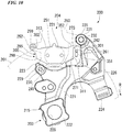
- the back plate 295 is formed of a single plate, and as shown in FIG. 10 , includes a main plate part 298, an arm part 299 extending obliquely outward from an end portion on one end side in a length direction of the main plate part 298 and the outer side in the disc radial direction, and an extended part 301 extending obliquely outward from an end portion on the other end side in the length direction of the main plate part 298 and the outer side in the disc radial direction.
- a pin hole 302 is formed in the arm part 299 in a thickness direction of the back plate 295.
- the pin hole 302 is an elongated hole that is long in the disc rotation direction.
- the main plate part 298 has a shape that is long in the disc rotation direction.
- the lining material 296 is affixed to the main plate part 298.
- the arm part 299 extends in a direction inclined with respect to a longitudinal direction of the main plate part 298 from the outer side in the disc radial direction of an end portion of the forward disc rotation entry side which is one side in the longitudinal direction of the main plate part 298.
- the extended part 301 extends in a direction inclined with respect to the longitudinal direction of the main plate part 298 from the outer side in the disc radial direction of an end portion on the forward disc rotation exit side which is the other side in the longitudinal direction of the main plate part 298.
- the longitudinal direction of the main plate part 298 is a longitudinal direction of the back plate 295.
- the longitudinal direction of the main plate part 298 is a longitudinal direction of the friction pad 205. Therefore, the arm part 299 and the extended part 301 extending in a direction inclined with respect to the longitudinal direction of the friction pad 205 are formed in the back plate 295 on both end portion sides in the disc rotation direction and an outer side in the disc radial direction.
- the main plate part 298 has substantially a mirror-symmetrical shape.
- a shape of the arm part 299 and the extended part 301 is asymmetric.
- the extended part 301 extends in a direction away from the main plate part 298 in the longitudinal direction of the main plate part 298 from one end portion side in the disc rotation direction and an outer side in the disc radial direction of the main plate part 298.
- the extended part 301 is inclined such that it is positioned further outward in the disc radial direction in the second reference line direction toward an extended distal end side.
- the main plate part 298 includes a side surface portion 311 which is a flat surface extending perpendicular to the longitudinal direction of the main plate part 298 on one side thereof in the longitudinal direction which is a base position of the extended part 301.
- the main plate part 298 includes an outer surface portion 313 along an outer circumferential surface of the disc rotor 201 on the outer side in the disc radial direction.
- the side surface portion 311 is a flat surface extending in a plate thickness direction of the back plate 121.
- the extended part 301 extends to become further away from the main plate part 298 obliquely with respect to the longitudinal direction of the friction pad 205 and the second reference line direction from between the side surface portion 311 and the outer surface portion 313.
- the extended part 301 includes a surface portion 351 (facing surface portion) on the inner side in the disc radial direction and a surface portion 352 on the outer side in the disc radial direction.
- the surface portions 351 and 352 are both flat surfaces extending in the plate thickness direction of the back plate 121.
- the surface portion 351 extends outward in the disc radial direction and toward the forward disc rotation exit side obliquely with respect to the longitudinal direction of the friction pad 205 and the second reference line direction from an end edge portion of the side surface portion 311 on the outer side in the disc radial direction.
- the surface portion 351 and the side surface portion 311 form an obtuse angle.
- An angle formed by the surface portion 351 and the side surface portion 311 is equivalent to the angle formed by the flat surface portion 273 and the torque receiving surface 271 of the pad support part 261.
- the surface portion 352 extends outward in the disc radial direction and toward the forward disc rotation exit side obliquely with respect to the longitudinal direction of the friction pad 205 and the second reference line direction from an end edge portion of the outer surface portion 313 on the forward disc rotation exit side.
- the surface portion 352 extends substantially parallel to the surface portion 351.
- the arm part 299 thereof is supported by the pad pin 252 on the forward disc rotation entry side inserted into the pin hole 302. Also, in this posture of the outer friction pad 205, the extended part 301 thereof is supported by the outer pad support part 261 on the forward disc rotation exit side.
- the outer friction pad 205 is pressed inward in the disc radial direction and toward the forward disc rotation exit side by a pad spring (not shown) provided in the caliper 204. Then, the extended part 301 disposed on the forward disc rotation exit side comes into direct contact with the flat surface portion 273 of the outer pad support part 261 at the surface portion 351 by surface contact. Also, the main plate part 298 comes into direct contact with the torque receiving surface 271 of the pad support part 261 at the side surface portion 311 by surface contact.
- the outer pad support part 261 of the bracket 215 includes the flat surface portion 273 that extends in a direction in which the extended part 301 of the outer friction pad 205 extends. Also, in this state, the extended part 301 of the outer friction pad 205 is locked to the outer pad support part 261. Also, in this state, the extended part 301 of the outer friction pad 205 is disposed on an outer side in the disc radial direction with respect to an outermost circumference of the disc rotor 11. Further, in this state, the torque receiving surface 271 of the outer pad support part 261 faces in a direction in which the outer friction pad 205 is disposed.
- the arm part 299 thereof is supported by the pad pin 252 on the forward disc rotation entry side inserted into the pin hole 302. Also, in this posture of the inner friction pad 205, the extended part 301 thereof is supported by the inner pad support part 262 on the forward disc rotation exit side.
- the inner friction pad 205 is pressed inward in the disc radial direction and toward the forward disc rotation exit side by the pad spring (not shown) provided in the caliper 204. Then, the extended part 301 disposed on the forward disc rotation exit side comes into direct contact with the flat surface portion 283 of the inner pad support part 262 at the surface portion 351 by surface contact. Also, the main plate part 298 comes into direct contact with the torque receiving surface 281 of the pad support part 262 at the side surface portion 311 by surface contact.
- the inner pad support part 262 of the bracket 215 includes the flat surface portion 283 that extends in a direction in which the extended part 301 of the inner friction pad 205 extends. Also, in this state, the extended part 301 of the inner friction pad 205 is locked to the inner pad support part 262. Also, in this state, the extended part 301 of the inner friction pad 205 is disposed on an outer side in the disc radial direction with respect to the outermost circumference of the disc rotor 11. Further, in this state, the torque receiving surface 281 of the inner pad support part 262 faces in a direction in which the inner friction pad 205 is disposed. As described above, the pair of friction pads 205 are locked to the bracket 215.
- the outer friction pad 205 is supported by the outer pad support part 261 of the bracket 215 and the pad pin 252 of the caliper 204 and moves in the disc axial direction. At that time, the pad support part 261 locks the extended part 301 of the outer friction pad 205.
- the inner friction pad 205 is supported by the inner pad support part 262 of the bracket 215 and the pad pin 252 of the caliper 204 and moves in the disc axial direction. At that time, the pad support part 262 locks the extended part 301 of the inner friction pad 205.
- the piston 251 moves forward in a direction of the disc rotor 201 in the disc axial direction with respect to the cylinder part 255, and presses the outer friction pad 205 against the disc rotor 201. Then, the outer friction pad 205 comes into contact with one surface of the disc rotor 201 via the lining material 296. Also, due to a reaction force generated thereby, the caliper main body 250 slides on the slide pins 241 and 242 of the carrier 203 and moves in a direction of separating the cylinder part 255 from the disc rotor 201.
- the claw part 257 presses the lining material 296 of the inner friction pad 205 against the other surface of the disc rotor 201.
- the caliper 204 applies a brake to rotation of the disc rotor 201, that is, the wheel, by the claw part 257 and the piston 251 sandwiching the pair of friction pads 205 from both sides and pressing against the disc rotor 201.
- the pair of friction pads 205 are locked to the carrier 203 and the caliper 204 so that inward movement in the disc radial direction and movement in the disc rotation direction are restricted by the pad supports parts 261 and 262 and the pad pins 252, and move in the disc axial direction.
- the bracket 215 including the pad support parts 261 and 262 locks the friction pads 205 to be movable in the disc axial direction.
- both the pair of friction pads 205 come into contact with the disc rotor 201 via the lining materials 296 and move to the forward disc rotation exit side. Then, the outer friction pad 205 comes into direct contact with the torque receiving surface 271 of the outer pad support part 261 at the side surface portion 311 of the back plate 295 by surface contact. Also, the inner friction pad 205 comes into direct contact with the torque receiving surface 281 of the inner pad support part 262 at the side surface portion 311 of the back plate 295 by surface contact. Thereby, the bracket 215 receives a braking torque mainly at the pad support parts 261 and 262.
- both the pair of friction pads 205 come into contact with the disc rotor 201 via the lining materials 296, move to a rearward disc rotation exit side, and come into contact with the pad pin 252 at the arm part 299 of the back plate 295.
- the caliper 204 receives a braking torque mainly at the pad pin 252.
- the extended part 301 extending in a direction inclined with respect to the longitudinal direction of the friction pad 205 is formed on an end portion side in the disc rotation direction and an outer side in the disc radial direction of the back plate 295 of the friction pad 205.
- the bracket 215 that locks the friction pad 205 to be movable in the disc axial direction includes the pad support part 261 having the flat surface portion 273 that extends in a direction in which the extended part 301 of the outer friction pad 205 extends, and the pad support part 262 having the flat surface portion 283 that extends in a direction in which the extended part 301 of the inner friction pad 205 extends.
- the extended part 301 of the outer friction pad 205 is brought into contact with the flat surface portion 273 and locked to the pad support part 261. Also, the extended part 301 of the inner friction pad 205 is brought into contact with the flat surface portion 283 and locked to the pad support part 262.
- lengths of the extended part 301 of the outer friction pad 205 and the outer pad support part 261 of the bracket 215 in the disc rotation direction can be reduced while maintaining a contact length between the extended part 301 of the outer friction pad 205 and the flat surface portion 273.
- lengths of the extended part 301 of the inner friction pad 205 and the inner pad support part 262 of the bracket 215 in the disc rotation direction can be reduced while maintaining a contact length between the extended part 301 of the inner friction pad 205 and the flat surface portion 283. Therefore, the friction pad 205 and the bracket 215 can be reduced in size in the disc rotation direction. Therefore, particularly, costs of parts of the bracket 215 can be reduced.
- the contact length between the extended part 301 of the outer friction pad 205 and the flat surface portion 273 can be increased without increasing the lengths of the extended part 301 of the outer friction pad 205 and the outer pad support part 261 in the disc rotation direction, and thereby a contact area can be increased.
- the contact length between the extended part 301 of the inner friction pad 205 and the flat surface portion 283 can be increased without increasing lengths of the extended part 301 of the inner friction pad 205 and the inner pad support part 262 in the disc rotation direction, and thereby a contact area can be increased. Therefore, a vibration load of the friction pad 205 received by the bracket 215 can be dispersed. Therefore, wear of the bracket 215 can be suppressed without interposing a retainer as a countermeasure against wear between the extended parts 301 of the pair of friction pads 205 and the pad support parts 261 and 262.
- a structure can be made such that the flat surface portion 273 of the pad support part 261 is brought into direct contact with the facing surface portion 351 of the extended part 301 of the outer friction pad 205, and the flat surface portion 283 of the pad support part 262 is brought into direct contact with the facing surface portion 351 of the extended part 301 of the inner friction pad 205. Therefore, the structure is made such that a retainer as a countermeasure against wear is not interposed between the extended parts 301 of the pair of friction pads 205 and the pad support parts 261 and 262, and thus the number of parts can be reduced. Therefore, costs of parts and assembly man-hours can be reduced. In addition, it is not necessary to secure a space for disposing a retainer, and thus a degree of freedom in design increases.
- the extended parts 301 of the friction pads 205 on both the outer side and inner side are disposed on an outer side in the disc radial direction with respect to the outermost circumference of the disc rotor 11. Therefore, the flat surface portions 273 and 283 of the pad support parts 261 and 262 supporting the extended parts 301 can be easily made as surfaces exposed to the outside on the outer side in the disc radial direction. Therefore, the flat surface portions 273 and 283 can be formed by casting without a core. Therefore, the flat surface portions 273 and 283 can be formed without using or processing a core, and thus manufacturing costs can be reduced.
- the flat surface portion 273 of the pad support part 261 and the flat surface portion 283 of the pad support part 262 are continuous in the disc axial direction due to the connecting surface portion 287. Thereby, stress concentration occurring in the bracket 215 can be minimized and reliability can be improved.
- FIGS. 13 to 15 a third embodiment according to the present invention will be described mainly on the basis of FIGS. 13 to 15 , focusing on differences from the first embodiment. Parts common to those in the first embodiment are denoted by the same terms and the same reference signs.
- a caliper 12a that is partially different from the caliper 12 is used.
- the caliper 12a uses a caliper main body 15a (locking member) that is partially different from the caliper main body 15.
- the caliper main body 15a includes a pad support part 32Ba, that is partially different from the pad support part 32B on the disc rotation entry side of the first embodiment, on an inner side.
- the caliper main body 15a includes a pad support part 33Aa, that is partially different from the pad support part 33A on the disc rotation entry side of the first embodiment, on an outer side.
- the inner pad support part 32Ba is provided to extend to an outer side in a disc radial direction with respect to the pad support part 32B of the first embodiment. Therefore, as shown in FIG. 15 , the pad support part 32Ba is provided to extend to an outer side in the disc radial direction with respect to a pad support part 33B on a disc rotation exit side. Therefore, similarly to the torque receiving surface 71B, the pad support part 32Ba includes a torque receiving surface 71Ba extending to an outer side in the disc radial direction with respect to the torque receiving surface 71B.
- the pad support part 32Ba includes a rotor facing surface 72Ba extending to an outer side in the disc radial direction with respect to the rotor facing surface 72B.
- the pad support part 32Ba similarly to the flat surface portion 73B, includes a flat surface portion 73Ba disposed on an outer side in the disc radial direction with respect to the flat surface portion 73B.
- the torque receiving surface 71Ba is parallel to a torque receiving surface 81B.
- An angle formed by the torque receiving surface 71Ba and the flat surface portion 73Ba is equivalent to an angle formed by the torque receiving surface 81B and a flat surface portion 83B.
- a line connecting a boundary position 398 between the flat surface portion 83B and the torque receiving surface 81B of the pad support part 33B to a boundary position 399 between the flat surface portion 73Ba and the torque receiving surface 71Ba becomes farther in distance toward the boundary position 399 side with respect to a line connecting the torque receiving surface 81B and the torque receiving surface 71Ba perpendicularly to each other. Therefore, the boundary position 399 between the flat surface portion 73Ba and the torque receiving surface 71Ba is disposed on an outer side in the disc radial direction with respect to the boundary position 398 between the flat surface portion 83B and the torque receiving surface 81B.
- the inner end position 399 of the flat surface portion 73Ba in the disc radial direction is disposed on an outer side in the disc radial direction with respect to the inner end position 398 of the flat surface portion 83B in the disc radial direction.
- a length of a line connecting the inner end position 399 of the flat surface portion 73Ba in the disc radial direction to a central axis of a disc rotor 11 is larger than a length of a line connecting the inner end position 398 of the flat surface portion 83B in the disc radial direction to the central axis of the disc rotor 11.
- the boundary position 399 between the torque receiving surface 71Ba facing a direction in which a friction pad 102a is disposed and the flat surface portion 73Ba facing outward in the disc radial direction in the pad support part 32Ba on the disc rotation entry side is disposed on an outer side in the disc radial direction with respect to the boundary position 398 between the torque receiving surface 81B facing the direction in which the friction pad 102a is disposed and the flat surface portion 83B facing outward in the disc radial direction in the pad support part 33B on the disc rotation exit side.
- the pad support part 32Ba and the pad support part 33B are different in that the boundary position 399 between the torque receiving surface 71Ba and the flat surface portion 73Ba and the boundary position 398 between the torque receiving surface 81B and the flat surface portion 83B on the outer side in the disc radial direction are respectively on one side and on the other side in a disc rotation direction.
- the outer pad support part 33Aa shown in FIG. 13 is provided to extend to an outer side in the disc radial direction with respect to the pad support part 33A of the first embodiment. Therefore, the pad support part 33Aa is provided extend to the outer side in the disc radial direction with respect to the pad support part 32A on the disc rotation exit side. Therefore, similarly to the torque receiving surface 81A, the pad support part 33Aa includes a torque receiving surface 81Aa extending to the outer side in the disc radial direction with respect to the torque receiving surface 81A.
- the pad support part 33Aa includes a rotor facing surface 82Aa extending to the outer side in the disc radial direction with respect to the rotor facing surface 82A.
- the pad support part 33Aa includes a flat surface portion 83Aa disposed on the outer side in the disc radial direction with respect to the flat surface portion 83 A.
- the torque receiving surface 81Aa is parallel to a torque receiving surface 71A.
- An angle formed by the torque receiving surface 81Aa and the flat surface portion 83Aa is equivalent to an angle formed by the torque receiving surface 71A and a flat surface portion 73A.
- the angle formed by the torque receiving surface 81Aa and the flat surface portion 83Aa is equivalent to an angle formed by the torque receiving surface 71Ba and the flat surface portion 73Ba.
- the torque receiving surface 81Aa is disposed on the same plane as the torque receiving surface 71Ba.
- the flat surface portion 83Aa is disposed on the same plane as the flat surface portion 73Ba.
- a distance between the torque receiving surface 71A and the torque receiving surface 81Aa is equivalent to a distance between the torque receiving surface 71Ba and the torque receiving surface 81B.
- a line connecting a boundary position between the flat surface portion 73 A and the torque receiving surface 71A of the pad support part 32A to a boundary position between the flat surface portion 83Aa and the torque receiving surface 81Aa becomes farther in distance toward a boundary position side between the flat surface portion 83Aa and the torque receiving surface 81Aa with respect to a line connecting the torque receiving surface 71A and the torque receiving surface 81Aa perpendicularly to each other. Therefore, the boundary position between the flat surface portion 83Aa and the torque receiving surface 81Aa is disposed on an outer side in the disc radial direction with respect to the boundary position between the flat surface portion 73 A and the torque receiving surface 71A.
- the boundary position between the flat surface portion 83Aa and the torque receiving surface 81Aa is aligned with the boundary position 399 between the flat surface portion 73Ba and the torque receiving surface 71Ba shown in FIG. 15 in the disc radial direction.
- an inner end position of the flat surface portion 83Aa in the disc radial direction is disposed on an outer side in the disc radial direction with respect to an inner end position of the flat surface portion 73A in the disc radial direction.
- a length of a line connecting the inner end position of the flat surface portion 83Aa in the disc radial direction to the central axis of the disc rotor 11 is larger than a length of a line connecting the inner end position of the flat surface portion 73A in the disc radial direction to the central axis of the disc rotor 11.
- the inner end position of the flat surface portion 83Aa in the disc radial direction and the inner end position 399 of the flat surface portion 73Ba in the disc radial direction are aligned in the disc radial direction.
- the boundary position of the pad support part 33Aa on the disc rotation entry side between the torque receiving surface 81Aa facing the direction in which the friction pad 102a is disposed and the flat surface portion 83Aa facing outward in the disc radial direction is disposed on an outer side in the disc radial direction with respect to the boundary position of the pad support part 32A on the disc rotation exit side between the torque receiving surface 71A facing the direction in which the friction pad 102a is disposed and the flat surface portion 73A facing outward in the disc radial direction.
- the pad support part 33Aa and the pad support part 32A are different in that the boundary position between the torque receiving surface 81Aa and the flat surface portion 83Aa and the boundary position between the torque receiving surface 71A and the flat surface portion 73 A on the outer side in the disc radial direction are respectively on one side and on the other side in the disc rotation direction.
- the friction pad 102a which is partially different from the friction pad 102 is used.
- one lining material 122a is affixed to a back plate 121 similar to the back plate 121 of the first embodiment.
- the extended part 131 is supported by the pad support part 32Ba on the forward disc rotation entry side and the extended part 132 is supported by the pad support part 33B on the forward disc rotation exit side in a posture of the friction pad 102a in which the lining material 122a is disposed on an outer side of the back plate 121 and the extended parts 131 and 132 are disposed on the outer side in the disc radial direction.
- the extended part 132 disposed on the forward disc rotation exit side comes into contact with a bent part 119 of an extended plate part 115 of a pad spring 101 at a surface portion 162 and is pressed inward in the disc radial direction and toward the forward disc rotation exit side by the bent part 119.
- the extended part 132 comes into contact with the flat surface portion 83B of the pad support part 33B at a surface portion 161.
- the extended part 131 on the forward disc rotation entry side comes into contact with an extended plate part 117 of the pad spring 101 at a surface portion 153 and is pressed inward in the disc radial direction by the extended plate part 117.
- the extended part 131 comes into contact with the flat surface portion 73Ba of the pad support part 32Ba at a surface portion 151.
- the biasing force of the pad spring 101 brings a side surface portion 142 of a main plate part 130 into direct contact with the facing torque receiving surface 81B on the inner side and the forward disc rotation exit side by surface contact, brings the surface portion 161 of the extended part 132 into direct contact with the facing flat surface portion 83B on the inner side and the forward disc rotation exit side by surface contact, and brings the surface portion 151 of the extended part 131 into direct contact with the facing flat surface portion 73Ba on the inner side and the forward disc rotation entry side by surface contact.
- the inner pad support part 32Ba of the caliper main body 15a includes the flat surface portion 73Ba that extends in a direction in which the extended part 131 of the inner friction pad 102a extends. In this state, the extended part 131 of the inner friction pad 102a is locked to the inner pad support part 32Ba. Also, in this state, the inner pad support part 33B of the caliper main body 15a includes the flat surface portion 83B that extends in a direction in which the extended part 132 of the inner friction pad 102a extends. In this state, the extended part 132 of the inner friction pad 102a is locked to the inner pad support part 33B.
- the inner friction pad 102a brings the side surface portion 142 of the main plate part 130 into contact with the torque receiving surface 81B, and causes a side surface portion 141 of the main plate part 130 to face the torque receiving surface 71Ba with a slight gap therebetween. Further, in this state, the extended parts 131 and 132 of the inner friction pad 102a are disposed on an outer side in the disc radial direction with respect to an outermost circumference of the disc rotor 11.
- the extended part 131 is supported by the pad support part 32A on the forward disc rotation exit side and the extended part 132 is supported by the pad support part 33Aa on the forward disc rotation entry side in a posture of the friction pad 102a in which the lining material 122a is disposed on an inner side of the back plate 121 and the extended parts 131 and 132 are disposed on the outer side in the disc radial direction.
- the extended part 131 disposed on the forward disc rotation exit side comes into contact with a bent part 118 of an extended plate part 114 of the pad spring 101 at a surface portion 152 and is pressed inward in the disc radial direction and toward the forward disc rotation exit side by the bent part 118.
- the extended part 131 comes into contact with the flat surface portion 73 A of the pad support part 32A at the surface portion 151.
- the extended part 132 on the forward disc rotation entry side comes into contact with an extended plate part 116 of the pad spring 101 at a surface portion 163 and is pressed inward in the disc radial direction by the extended plate part 116.
- the extended part 132 comes into contact with the flat surface portion 83Aa of the pad support part 33Aa at the surface portion 161.
- the biasing force of the pad spring 101 brings the side surface portion 141 of the main plate part 130 into direct contact with the facing torque receiving surface 71A on the outer side and the forward disc rotation exit side by surface contact, brings the surface portion 151 of the extended part 131 into direct contact with the facing flat surface portion 73A on the outer side and the forward disc rotation exit side by surface contact, and brings the surface portion 161 of the extended part 132 into direct contact with the facing flat surface portion 83Aa on the outer side and the forward disc rotation entry side by surface contact.
- the outer pad support part 32A of the caliper main body 15a includes the flat surface portion 73A that extends in a direction in which the extended part 131 of the outer friction pad 102a extends. In this state, the extended part 131 of the outer friction pad 102a is locked to the outer pad support part 32A. Also, in this state, the outer pad support part 33Aa of the caliper main body 15a includes the flat surface portion 83Aa that extends in a direction in which the extended part 132 of the outer friction pad 102a extends. In this state, the extended part 132 of the outer friction pad 102a is locked to the outer pad support part 33Aa. Also, in this state, as shown in FIG.
- the outer friction pad 102a brings the side surface portion 141 of the main plate part 130 into contact with the torque receiving surface 71A, and causes the side surface portion 142 of the main plate part 130 to face the torque receiving surface 81Aa with a slight gap therebetween. Further, in this state, the extended parts 131 and 132 of the outer friction pad 102a shown in FIG. 13 are disposed on an outer side in the disc radial direction with respect to the outermost circumference of the disc rotor 11. As described above, the pair of friction pads 102a are locked to one caliper main body 15a.
- the inner friction pad 102a shown in FIG. 15 is supported by the inner pad support parts 32Ba and 33B of the caliper main body 15a and moves in the disc axial direction. At that time, the pad support parts 32Ba and 33B lock the extended parts 131 and 132 of the inner friction pad 102a with the flat surface portions 73Ba and 83B disposed in a V shape on both sides in the disc rotation direction.
- the outer friction pad 102a shown in FIG. 13 is supported by the outer pad support parts 32Aand 33Aa of the caliper main body 15a and moves in the disc axial direction. At that time, the pad support parts 32A and 33Aa lock the extended parts 131 and 132 of the outer friction pad 102a with the flat surface portions 73A and 83Aa disposed in a V shape on both sides in the disc rotation direction.
- pistons 16 and 17 on the outer sides shown in FIG. 14 press the outer friction pad 102a against the disc rotor 11, and pistons 16 and 17 on the inner side press the inner friction pad 102a against the disc rotor 11. Then, the pair of friction pads 102a are locked to the caliper main body 15a so that inward movement in the disc radial direction and movement in the disc rotation direction are restricted by the pad support parts 32A, 33Aa, 32Ba, and 33B, and move in the disc axial direction.
- the inner friction pad 102a shown in FIG. 15 is supported by the inner pad support parts 32Ba and 33B at the extended parts 131 and 132 and moves.
- the extended part 132 slides on the flat surface portion 83B of the pad support part 33B by the surface portion 161
- the extended part 131 slides on the flat surface portion 73Ba of the pad support part 32Ba by the surface portion 151.
- the outer friction pad 102a shown in FIG. 13 is locked to the outer pad support parts 32A and 33Aa at the extended parts 131 and 132 and moves.
- the extended part 131 slides on the flat surface portion 73A of the pad support part 32A by the surface portion 151, and the extended part 132 slides on the flat surface portion 83Aa of the pad support part 33Aa by the surface portion 161.
- the caliper main body 15a including the pad support parts 32A, 33Aa, 32Ba, and 33B as described above locks the friction pad 102a to be movable in the disc axial direction.
- both the pair of friction pads 102a come into contact with the disc rotor 11 via the lining materials 122a and move to the forward disc rotation exit side. Then, as shown in FIG. 15 , the inner friction pad 102a comes into contact with the torque receiving surface 81B of the pad support part 33B, which is on the forward disc rotation exit side, at the side surface portion 142 of the back plate 121. Also, as shown in FIG. 14 , the outer friction pad 102a comes into contact with the torque receiving surface 71A of the pad support part 32A, which is on the forward disc rotation exit side, at the side surface portion 141 of the back plate 121. Thereby, the caliper main body 15a receives a braking torque mainly at the pad support parts 32A and 33B.
- both the friction pads 102a come into contact with the disc rotor 11 via the lining materials 122a and move to a rearward disc rotation exit side. Then, the inner friction pad 102a shown in FIG. 15 comes into contact with the torque receiving surface 71Ba of the pad support part 32Ba, which is the rearward disc rotation exit side, at the side surface portion 141 of the back plate 121, and the outer friction pad 102a shown in FIG. 13 comes into contact with the torque receiving surface 81Aa of the pad support part 33Aa, which is the rearward disc rotation exit side, at the side surface portion 142 of the back plate 121. Thereby, the caliper main body 15a receives the braking torque mainly at the pad support parts 32Ba and 33Aa.
- the flat surface portion 73Ba of the pad support part 32Ba on the forward disc rotation entry side is disposed on an outer side in the disc radial direction with respect to the flat surface portion 83B of the pad support part 33B on the forward disc rotation exit side.
- the flat surface portion 73Ba which is a locking surface for locking the extended part 131 of the inner friction pad 102a is disposed on an outer side in the disc radial direction with respect to the flat surface portion 83B which is a locking surface for locking the extended part 132 of the inner friction pad 102a.
- the inner friction pad 102a is tilted so that the extended part 131 on the forward disc rotation entry side is positioned on an inner side in the disc radial direction with respect to the extended part 132 on the forward disc rotation exit side by the biasing force of the pad spring 101.
- the inner friction pad 102a is tilted so that the side surface portion 142 makes line contact with the torque receiving surface 81B at a portion thereof on a side opposite to the extended part 132.
- such a tilt can be suppressed and the side surface portion 142 can be brought into contact with the torque receiving surface 81B by surface contact.
- torque wear resistance is improved, vibration resistance is improved, and occurrence of rattle noise and brake squeal can be suppressed.
- the flat surface portion 83Aa of the pad support part 33Aa on the forward disc rotation entry side shown in FIG. 13 is disposed on an outer side in the disc radial direction with respect to the flat surface portion 73 A of the pad support part 32A on the forward disc rotation exit side.
- the flat surface portion 83Aa which is a locking surface for locking the extended part 132 of the outer friction pad 102a is disposed on an outer side in the disc radial direction with respect to the flat surface portion 73 A which is a locking surface for locking the extended part 131 of the outer friction pad 102a.
- the outer friction pad 102a is tilted so that the extended part 132 on the forward disc rotation entry side is positioned on an inner side in the disc radial direction with respect to the extended part 131 on the forward disc rotation exit side by the biasing force of the pad spring 101.
- the outer friction pad 102a is tilted so that the side surface portion 141 makes line contact with the torque receiving surface 71A at a portion on a side opposite to the extended part 131 of the side surface portion 141.
- such a tilt can be suppressed and the side surface portion 141 can be brought into contact with the torque receiving surface 71A by surface contact.
- torque wear resistance is improved, vibration resistance is improved, and occurrence of rattle noise and brake squeal can be suppressed.
- the caliper main body 15b instead of the caliper main body 15, a caliper main body 15b (locking member) which is partially different from the caliper main body 15 is used.
- the caliper main body 15b includes a pad support part 33Bb which is partially different from the pad support part 33B on the forward disc rotation exit side of the first embodiment, and a pad support part 32Bb which is partially different from the pad support part 32B on the forward disc rotation entry side of the first embodiment.
- the pad support part 33Bb includes a pad locking recessed part 401.
- the pad locking recessed part 401 is recessed from the torque receiving surface 81B to the forward disc rotation exit side.
- the pad locking recessed part 401 has a flat surface portion 83Bb on an inner side in the disc radial direction.
- the flat surface portion 83Bb extends in the axial direction of the disc rotor 11.
- the flat surface portion 83Bb is inclined with respect to the first radial reference line.
- the flat surface portion 83Bb is inclined to become further away from the first radial reference line outward in the disc radial direction.
- the pad support part 32Bb includes a pad locking recessed part 402.
- the pad locking recessed part 402 is recessed from the torque receiving surface 71B to the forward disc rotation entry side.
- the pad locking recessed part 402 has a flat surface portion 73Bb on an inner side in the disc radial direction.
- the flat surface portion 73Bb extends in the axial direction of the disc rotor 11.
- the flat surface portion 73Bb is inclined with respect to the first radial reference line.
- the flat surface portion 73Bb is inclined to become further away from the first radial reference line outward in the disc radial direction.
- An angle formed by the flat surface portion 73Bb and the torque receiving surface 71B is equivalent to an angle formed by the flat surface portion 83Bb and the torque receiving surface 81B.
- the pad locking recessed part 401 on the forward disc rotation entry side is provided on an outer side in the disc radial direction with respect to the pad locking recessed part 402 on the forward disc rotation exit side. Therefore, the pad support part 32Bb includes the flat surface portion 73Bb disposed on an outer side with respect to the flat surface portion 83Bb in the disc radial direction.
- a line connecting a boundary position 398b between the flat surface portion 83Bb and the torque receiving surface 81B of the pad support part 33Bb to a boundary position 399b between the flat surface portion 73Bb and the torque receiving surface 71B becomes farther in distance toward the boundary position 399b side with respect to a line connecting the torque receiving surface 81B and the torque receiving surface 71B perpendicularly to each other on an inner side in the disc radial direction with respect to the pad locking recessed parts 401 and 402.
- the boundary position 399b between the flat surface portion 73Bb and the torque receiving surface 71B is disposed on an outer side in the disc radial direction with respect to the boundary position 398b between the flat surface portion 83Bb and the torque receiving surface 81B.
- the inner end position 399b of the flat surface portion 73Bb in the disc radial direction is disposed on an outer side in the disc radial direction with respect to the inner end position 398b of the flat surface portion 83Bb in the disc radial direction.
- a length of a line connecting the inner end position 399b of the flat surface portion 73Bb in the disc radial direction to the central axis of the disc rotor 11 is larger than a length of a line connecting the inner end position 398b of the flat surface portion 83Bb in the disc radial direction to the central axis of the disc rotor 11.
- a friction pad 102b that is partially different from the friction pad 102 is used.
- one lining material 122b is affixed to a back plate 121b which is partially different from the back plate 121 of the first embodiment.
- the back plate 121b includes a main plate part 130b to which the lining material 122b is affixed, and a pair of an extended part 131b and an extended part 132b which extends to both outer sides in the disc rotation direction from intermediate positions in the disc radial direction on both end portion sides of the main plate part 130b in the disc rotation direction.
- the extended part 131b and the extended part 132b extend in a direction inclined with respect to a longitudinal direction of the main plate part 130b from both end portion sides of the main plate part 130b in the disc rotation direction which are on both sides thereof in the longitudinal direction.
- the longitudinal direction of the main plate part 130b is a longitudinal direction of the back plate 121b and a longitudinal direction of the friction pad 102b.
- the pair of extended parts 131b and 132b extending in a direction inclined with respect to the longitudinal direction of the friction pad 102b are formed in the back plate 121b at intermediate portions in the disc radial direction on both end portion sides in the disc rotation direction.
- the main plate part 130b has a mirror-symmetrical outer shape.
- shapes of the extended part 131b and the extended part 132b are mirror symmetrical.
- the extended part 131b on one side includes a surface portion 151b (facing surface portion) on an inner side in the disc radial direction.
- the surface portion 151b (facing surface portion) extends in a direction away from the main plate part 130b in the longitudinal direction of the main plate part 130b from an intermediate portion of the main plate part 130b in the disc radial direction on one end portion side thereof in the disc rotation direction.
- the surface portion 151b of the extended part 131b is inclined such that it is positioned further outward in the disc radial direction in the first reference line direction toward an extended distal end side.
- the extended part 132b on the other side includes a surface portion 161b (facing surface portion) on an inner side in the disc radial direction.
- the surface portion 161b (facing surface portion) extends in a direction away from the main plate part 130b in the longitudinal direction of the main plate part 130b from an intermediate portion of the main plate part 130b in the disc radial direction on the other end portion side thereof in the disc rotation direction.
- the surface portion 161b of the extended part 132b is inclined such that it is positioned further outward in the disc radial direction in the first reference line direction toward an extended distal end side.
- the main plate part 130b includes a side surface portion 141b which is a flat surface extending perpendicular to the longitudinal direction of the main plate part 130b on one side thereof in the longitudinal direction which is a base position of the extended part 131b.
- the main plate part 130b includes a side surface portion 142b which is a flat surface extending perpendicular to the longitudinal direction of the main plate part 130b on the other side thereof in the longitudinal direction which is a base position of the extended part 132b.
- the surface portion 151b extends outward in the disc radial direction and outward in the disc rotation direction obliquely with respect to the longitudinal direction of the friction pad 102b and the first reference line direction from an intermediate portion of the side surface portion 141b in the disc radial direction.
- the surface portion 151b and the side surface portion 141b form an obtuse angle.
- the angle formed by the surface portion 151b and the side surface portion 141b is equivalent to an angle formed by the flat surface portion 73Bb and the torque receiving surface 71B of the pad support part 32Bb.
- the surface portion 161b extends outward in the disc radial direction and outward in the disc rotation direction obliquely with respect to the longitudinal direction of the friction pad 102b and the first reference line direction from an intermediate portion of the side surface portion 142b in the disc radial direction.
- the surface portion 161b and the side surface portion 142b form an obtuse angle.
- the angle formed by the surface portion 161b and the side surface portion 142b is equivalent to an angle formed by the surface portion 151b and the side surface portion 141b.
- the angle formed by the surface portion 161b and the side surface portion 142b is equivalent to an angle formed by the flat surface portion 83Bb and the torque receiving surface 81B of the pad support part 33Bb.
- a line connecting a boundary position between the surface portion 161b and the side surface portion 142b to a boundary position between the surface portion 151b and the side surface portion 141b is parallel to a line connecting the side surface portion 141b and the side surface portion 142b perpendicularly to each other.
- a distance between the side surface portion 141b and the side surface portion 142b is smaller than a distance between the torque receiving surface 71B and the torque receiving surface 81B.
- a maximum distance between the surface portion 151b and the surface portion 161b is larger than a distance between the torque receiving surface 71B and the torque receiving surface 81B.
- the extended part 131b is supported by the pad locking recessed part 402 of pad support part 32Bb on the forward disc rotation entry side in a posture of the friction pad 102b in which the lining material 122b is disposed on an outer side of the back plate 121b and the surface portions 151b and 161b are disposed on an inner side in the disc radial direction in the extended parts 131b and 132b.
- the extended part 132b is supported by the pad locking recessed part 401 of the pad support part 33B on the forward disc rotation exit side.
- the forward disc rotation exit side of the friction pad 102b disposed on the inner side is pressed inward in the disc radial direction and the forward disc rotation exit side by the pad spring (not shown).
- the extended part 132b comes into contact with the flat surface portion 83Bb of the pad support part 33Bb at the surface portion 161b thereof.
- the forward disc rotation entry side of the friction pad 102b is pressed inward in the disc radial direction by the pad spring (not shown).
- the extended part 131b comes into contact with the flat surface portion 73Bb of the pad support part 32Bb at the surface portion 151b thereof.
- the biasing force of the pad spring brings the side surface portion 142b of the main plate part 130b into direct contact with the facing torque receiving surface 81B on the inner side and the forward disc rotation exit side by surface contact, brings the surface portion 161b of the extended part 132b into direct contact with the facing flat surface portion 83Bb on the inner side and the forward disc rotation exit side by surface contact, and brings the surface portion 151b of the extended part 131b into direct contact with the facing flat surface portion 73Bb on the inner side and the forward disc rotation entry side by surface contact.
- the inner pad support part 32Bb of the caliper main body 15b includes the flat surface portion 73Bb that extends in a direction in which the surface portion 151b of the extended part 131b of the inner friction pad 102b extends. In this state, the extended part 131b of the inner friction pad 102b is locked to the inner pad support part 32Bb. Also, in this state, the inner pad support part 33Bb of the caliper main body 15b includes the flat surface portion 83Bb that extends in a direction in which the surface portion 161b of the extended part 132b of the inner friction pad 102b extends. In this state, the extended part 132b of the inner friction pad 102b is locked to the inner pad support part 33Bb.
- the inner friction pad 102b brings the side surface portion 142b of the main plate part 130b into contact with the torque receiving surface 81B, and causes the side surface portion 141b of the main plate part 130b to face the torque receiving surface 71B with a slight gap therebetween.
- the inner friction pad 102b is supported by the inner pad support parts 32Bb and 33Bb of the caliper main body 15b and moves in the disc axial direction. At that time, the pad support parts 32Bb and 33Bb lock the extended parts 131b and 132b of the inner friction pad 102b with the flat surface portions 73Bb and 83Bb disposed in a V shape on both sides in the disc rotation direction.
- the inner friction pad 102b moves in the disc axial direction, it is supported by the inner pad support parts 32Bb and 33Bb at the extended parts 131b and 132b and moves. At that time, the extended part 132b slides on the flat surface portion 83Bb of the pad support part 33Bb by the surface portion 161b, and the extended part 131b slides on the flat surface portion 73Bb of the pad support part 32Bb by the surface portion 151b.
- the caliper main body 15b including the pad support parts 32Bb and 33Bb as described above locks the friction pad 102b to be movable in the disc axial direction.
- the inner friction pad 102b comes into contact with the disc rotor 11 via the lining material 122b and moves to the forward disc rotation exit side. Then, the friction pad 102b comes into contact with the torque receiving surface 81B of the pad support part 33Bb, which is on the forward disc rotation exit side, at the side surface portion 142b of the back plate 121b. Thereby, the caliper main body 15b receives a braking torque of the inner friction pad 102b mainly at the pad support part 33Bb.
- the inner friction pad 102b comes into contact with the disc rotor 11 via the lining material 122b and moves to the rearward disc rotation exit side. Then, the friction pad 102b comes into contact with the torque receiving surface 71B of the pad support part 32Bb, which is on the rearward disc rotation exit side, at the side surface portion 141b of the back plate 121b. Thereby, the caliper main body 15b receives a braking torque of the inner friction pad 102b mainly at the pad support part 32Bb.
- the flat surface portion 73Bb of the pad support part 32Bb on the forward disc rotation entry side is disposed on an outer side in the disc radial direction with respect to the flat surface portion 83Bb of the pad support part 33Bb on the forward disc rotation exit side.
- the flat surface portion 73Bb which is a locking surface for locking the extended part 131b of the inner friction pad 102b is disposed on an outer side in the disc radial direction with respect to the flat surface portion 83Bb which is a locking surface for locking the extended part 132b of the inner friction pad 102b.
- the inner friction pad 102b is tilted so that the extended part 131b on the forward disc rotation entry side is positioned on an inner side in the disc radial direction with respect to the extended part 132b on the forward disc rotation exit side by the biasing force of the pad spring.
- the inner friction pad 102b is tilted so that the side surface portion 142b makes line contact with the torque receiving surface 81B at a portion thereof on the inner side in the disc radial direction.
- such a tilt can be suppressed, and the side surface portion 142b can be brought into contact with the torque receiving surface 81B by surface contact.
- torque wear resistance is improved, vibration resistance is improved, and occurrence of rattle noise and brake squeal can be suppressed.
- a first aspect of the present embodiment described above includes a locking member which locks a friction pad to be movable in a disc axial direction, and a pressing member which presses the friction pad against a disc rotor.
- the friction pad includes a lining material which comes into contact with the disc rotor, and a back plate to which the lining material is affixed.
- An extended part extending in a direction inclined with respect to a longitudinal direction of the friction pad is formed in the back plate on an end portion side in a disc rotation direction.
- the locking member includes a pad support part having a flat surface portion extending in a direction in which the extended part extends. The extended part is locked to the pad support part. Thereby, costs can be reduced.
- the extended part of the friction pad is disposed on an outer side in a disc radial direction with respect to an outermost circumference of the disc rotor.
- the flat surface portion of the pad support part comes into direct contact with a facing surface portion of the extended part facing the flat surface portion.
- a pair of friction pads are locked to the locking member.
- the locking member includes a pair of cylinder parts in which pistons as the pressing member are accommodated and disposed to face each other, and a pair of connection parts which connect the pair of cylinder parts across the disc rotor at end portions of the pair of cylinder parts in the disc rotation direction.
- the pad support part is provided in each of the connection parts.
- the locking member is configured so that the flat surface portion of the pad support part which locks the extended part of the friction pad on one side is continuous in the disc axial direction with the flat surface portion of the pad support part which locks the extended part of the friction pad on the other side.
- the pad support part on a disc rotation entry side is disposed on an outer side in the disc radial direction with respect to the pad support part on a disc rotation exit side.
- a boundary position of the pad support part on the disc rotation entry side between a torque receiving surface facing a direction in which the friction pad is disposed and a flat surface portion facing outward in the disc radial direction is disposed on an outer side in the disc radial direction with respect to a boundary position of the pad support part on the disc rotation exit side between a torque receiving surface facing a direction in which the friction pad is disposed and a flat surface portion facing outward in the disc radial direction.
- An eighth aspect is a caliper including a pad support part which supports a pair of friction pads provided to face each other across a disc rotor to be able to press against the disc rotor.
- the pad support part is constituted by a torque receiving surface facing a direction in which the friction pads are disposed, and a flat surface portion facing outward in a disc radial direction.
- the flat surface portion is inclined in a direction away from a center of the caliper in a rotor rotation direction.
- the pad support part is configured so that a boundary position between the torque receiving surface and the flat surface portion on an outer side in the disc radial direction is different between one side and the other side in the disc rotation direction.
Landscapes
- Engineering & Computer Science (AREA)
- General Engineering & Computer Science (AREA)
- Mechanical Engineering (AREA)
- Braking Arrangements (AREA)
Abstract
Description
- The present invention relates to a disc brake and a caliper for braking vehicles such as motorcycles and four-wheeled vehicles.
- Priority is claimed on Japanese Patent Application No.
2018-116902 - There is a disc brake having a structure in which an extended part extending in a longitudinal direction of a friction pad is formed on an end portion side in a disc rotation direction and an outer side in a disc radial direction of the friction pad, and the extended part is supported by a caliper main body (for example, see Patent Document 1).
- [Patent Document 1]
Japanese Unexamined Patent Application, First Publication No.2014-173623 - In a disc brake, cost reduction is required.
- An objective of the present invention is to provide a disc brake and a caliper in which costs can be reduced.
- In a first aspect of the present invention, a friction pad includes a lining material which comes into contact with a disc rotor, and a back plate to which the lining material is affixed. An extended part extending in a direction inclined with respect to a longitudinal direction of the friction pad is formed in the back plate on an end portion side in a disc rotation direction. A locking member which locks the friction pad to be movable in a disc axial direction includes a pad support part having a flat surface portion extending in a direction in which the extended part extends. The extended part is locked to the pad support part.
- In a second aspect of the present invention, a pad support part is constituted by a torque receiving surface facing a direction in which a friction pad is disposed, and a flat surface portion facing outward in a disc radial direction. The flat surface portion is inclined in a direction away from a center of a caliper in a rotor rotation direction.
- According to the disc brake and the caliper of the present invention, it is possible to reduce costs.
-
-
FIG. 1 is a view of a disc brake of a first embodiment from outside in a disc radial direction. -
FIG. 2 is a view taken in a direction of arrow II ofFIG. 1 showing the disc brake of the first embodiment. -
FIG. 3 is a view taken in a direction of arrow III ofFIG. 1 showing the disc brake of the first embodiment. -
FIG. 4 is a view of the disc brake of the first embodiment from inside in the disc radial direction. -
FIG. 5 is a cross-sectional view taken along line V-V ofFIG. 1 showing the disc brake of the first embodiment. -
FIG. 6 is a cross-sectional view of a main part showing the disc brake of the first embodiment. -
FIG. 7 is a perspective view of a main part showing the disc brake of the first embodiment. -
FIG. 8 is a view of a main part of the disc brake of the first embodiment from outside in the disc radial direction except for a pad spring. -
FIG. 9 is a view of a modified example of a main part of the disc brake of the first embodiment from outside in the disc radial direction except for the pad spring. -
FIG. 10 is a front view showing a disc brake of a second embodiment. -
FIG. 11 is a view of the disc brake of the second embodiment from outside in a disc radial direction. -
FIG. 12 is a perspective view showing a disc, a bracket, and a pair of friction pads of the disc brake of the second embodiment. -
FIG. 13 is a view of a disc brake of a third embodiment from outside in a disc radial direction. -
FIG. 14 is a view of the disc brake of the third embodiment from inside in the disc radial direction. -
FIG. 15 is a cross-sectional view taken along line XV-XV ofFIG. 13 showing the disc brake of the third embodiment. -
FIG. 16 is a cross-sectional view showing a main part of a modified example of the disc brake of the first embodiment. - A first embodiment according to the present invention will be described with reference to
FIGS. 1 to 9 . Adisc brake 10 of the first embodiment is an opposed piston type disc brake for front wheel braking of motorcycles. Further, the present invention is not limited thereto, and can also be applied to, for example, disc brakes for rear wheel braking of motorcycles and braking of four-wheeled vehicles as a matter of course. - As shown in
FIGS. 1 to 5 , thedisc brake 10 includes adisc rotor 11 that rotates together with a wheel to be braked, and acaliper 12 attached to a vehicle body side and configured to apply frictional resistance to thedisc rotor 11. Hereinafter, a radial direction in thedisc rotor 11 is referred to as a disc radial direction, a central axis of thedisc rotor 11 is referred to as a disc axis, a direction in which the disc axis extends is referred to as a disc axial direction, and a rotation direction (circumferential direction) of thedisc rotor 11 is referred to as a disc rotation direction. Also, a center side of thedisc rotor 11 in the disc radial direction is referred to as an inner side in the disc radial direction, and a side opposite to the center of thedisc rotor 11 in the disc radial direction is referred to as an outer side in the disc radial direction. - The
caliper 12 includes a caliper main body 15 (locking member) disposed across an outer circumferential side of thedisc rotor 11 and fixed to the vehicle body side as shown inFIGS. 1 to 3 , and a pair of pistons 16 (pressing members) of the same shape accommodated in the calipermain body 15 as shown inFIGS. 2 to 4 , and a pair of pistons 17 (pressing members) of the same shape having smaller diameters than those of thepistons 16 and accommodated in the calipermain body 15. In the first embodiment, a line in the disc radial direction through the disc axis of thedisc rotor 11 and a center of the calipermain body 15 in the disc rotation direction is referred to as a first radial reference line, and a direction in which the first radial reference line extends is referred to as a first reference line direction. The first radial reference line is perpendicular to the disc axis. - In the
caliper 12, the pair ofpistons 16, which are common parts, are provided in pairs on both sides of thedisc rotor 11 in the disc axial direction to be aligned in the disc radial direction and the disc rotation direction. Also, the pair ofpistons 17, which are common parts, are provided in pairs on both sides of thedisc rotor 11 in the disc axial direction to be aligned in the disc radial direction and the disc rotation direction. In other words, onepiston 16 and onepiston 17 are provided to be aligned in the disc rotation direction with a predetermined distance therebetween on one side of thedisc rotor 11 in the disc axial direction, and such a configuration is provided on both sides in the disc axial direction. Therefore, thecaliper 12 is an opposed piston type four-pot caliper. Further, the number of pistons may be at least one pair with thedisc rotor 11 interposed therebetween and may also be three or four pairs in addition to the above-described two pairs. Further, the number of pistons may be different on both sides of thedisc rotor 11 in the disc axial direction such as one and two or two and three. - As shown in
FIG. 1 , the calipermain body 15 includes acylinder part 21 disposed on an outer side of thedisc rotor 11 in the disc axial direction (on a side opposite to the wheel with respect to the disc rotor 11), and acylinder part 22 disposed on an inner side (on the wheel side with respect to the disc rotor 11) of thedisc rotor 11. Also, the calipermain body 15 includes an end side connection part 23 (connection part) that connects one end portions of thecylinder part 21 and thecylinder part 22 in the disc rotation direction, an end side connection part 24 (connection part) that connects the other end portions of thecylinder part 21 and thecylinder part 22 in the disc rotation direction, and anintermediate connection part 25 that connects intermediate portions of thecylinder part 21 and thecylinder part 22 in the disc rotation direction. The endside connection part 23, the endside connection part 24, and theintermediate connection part 25 are all disposed to cross thedisc rotor 11 on an outer side in the disc radial direction. In other words, the calipermain body 15 includes a pair of endside connection parts cylinder parts disc rotor 11 at end portions of the pair ofcylinder parts - The caliper
main body 15 is a monoblock caliper in which thecylinder part 21, thecylinder part 22, the endside connection part 23, the endside connection part 24, and theintermediate connection part 25 are formed of an integral cast material. Therefore, thecylinder part 21 and thecylinder part 22 are integrally formed via the endside connection part 23, the endside connection part 24, and theintermediate connection part 25. - As shown in
FIG. 4 , thecylinder part 21 on the outer side is disposed to face a surface on an outer side of thedisc rotor 11. Thecylinder part 21 on the outer side includes amounting boss part 34 disposed on the endside connection part 23 side which is one end in the disc rotation direction, and amounting boss part 35 disposed on the endside connection part 24 side which is the other end in the disc rotation direction. - The
cylinder part 21 has a shape longer in the disc rotation direction to accommodate a plurality ofpistons FIG. 2 , in thecylinder part 21, twocylinder bores pistons cylinder bores large diameter piston 16 is disposed on the endside connection part 23 side in the disc rotation direction. Also, of thecylinder bores diameter cylinder bore 39 accommodating asmall diameter piston 17 is disposed on the endside connection part 24 side in the disc rotation direction. The cylinder bores 38 and 39 open to thedisc rotor 11 side in the disc axial direction. - As shown in
FIG. 1 , a supply/discharge port 41 for supplying/discharging a brake fluid to the cylinder bores 38 and 39 is formed at a center position of thecylinder part 21 in the disc rotation direction. The supply/discharge port 41 is formed parallel to the first radial reference line. - A mounting
hole 44 and a mountinghole 45 are respectively formed to penetrate the mountingboss part 34 and the mountingboss part 35 in the disc radial direction. These mountingholes holes main body 15 in the disc rotation direction. Thecaliper 12 is a so-called radial mount type in which thecaliper 12 is fixed to the vehicle body side using mounting bolts (not shown) inserted into these mountingholes - A
bleeder boss part 49 to which ableeder plug 48 for bleeding air is attached is formed on the endside connection part 23. The calipermain body 15 is disposed on a rear side of thedisc rotor 11 in a vehicle front-rear direction with the endside connection part 23 on which thebleeder boss part 49 is formed disposed on an upper side in a vertical direction. Therefore, when the vehicle travels forward, thedisc rotor 11 moves upward from below in the vertical direction with respect to the calipermain body 15. In the calipermain body 15, the endside connection part 23 on one side on which thebleeder boss part 49 is disposed is disposed on a forward disc rotation exit side which is an exit side of thedisc rotor 11 in a rotation direction R when the vehicle travels forward. In the calipermain body 15, the endside connection part 24 on the other side is disposed on a forward disc rotation entry side which is an entry side of thedisc rotor 11 in the rotation direction R when the vehicle travels forward. - As shown in
FIG. 4 , thecylinder part 22 on the inner side is disposed to face a surface on an inner side of thedisc rotor 11. As shown inFIG. 3 , thecylinder part 22 on the inner side has a shape longer in the disc rotation direction to accommodate the plurality ofpistons cylinder part 22, two cylinder bores 58 and 59 that accommodate thepistons large diameter piston 16 is disposed on the endside connection part 23 side in the disc rotation direction. Of the cylinder bores 58 and 59, a small diameter cylinder bore 59 accommodating asmall diameter piston 17 is disposed on the endside connection part 24 side in the disc rotation direction. The cylinder bores 58 and 59 open to thedisc rotor 11 side in the disc axial direction. The supply/discharge port 41 of thecylinder part 21 on the outer side shown inFIG. 1 supplies/discharges the brake fluid to the cylinder bores 38 and 39 of thecylinder part 21 shown inFIG. 2 . In addition, the supply/discharge port 41 supplies/discharges the brake fluid also to the cylinder bores 58 and 59 of thecylinder part 22 shown inFIG. 3 . - In the caliper
main body 15, thecylinder part 21 shown inFIGS. 1 and2 and thecylinder part 22 shown inFIGS. 1 and3 are disposed to face in the disc axial direction while positions thereof in the disc rotation direction and the disc radial direction are aligned to be superimposed on each other. The cylinder bore 58 is formed coaxially with the cylinder bore 38, and the cylinder bore 59 is formed coaxially with the cylinder bore 39. - As shown in
FIG. 1 , the endside connection part 23 includes apad support part 32A and apad support part 33B on the endside connection part 24 side in the disc rotation direction. Thepad support part 32A is disposed on the outer side of thedisc rotor 11, and thepad support part 33B is disposed on the inner side of thedisc rotor 11. The endside connection part 24 includes apad support part 32B and apad support part 33A on the endside connection part 23 side in the disc rotation direction. The pad support part 33Ais disposed on the outer side of thedisc rotor 11, and thepad support part 32B is disposed on the inner side of thedisc rotor 11. Therefore, the endside connection part 23 includes thepad support parts disc rotor 11 in the disc axial direction. The endside connection part 24 includes thepad support parts disc rotor 11 in the disc axial direction. In other words, thepad support parts side connection parts main body 15, thepad support parts main body 15, thepad support parts - The
pad support part 32A and thepad support part 33B shown inFIGS. 1 and4 are disposed to face in the disc axial direction while positions thereof in the disc rotation direction and the disc radial direction are aligned to be superimposed on each other. Also, thepad support part 33A and thepad support part 32B are disposed to face in the disc axial direction while positions thereof in the disc rotation direction and the disc radial direction are aligned to be superimposed on each other. As shown inFIG. 4 , thedisc rotor 11 is disposed between: thepad support parts pad support parts side connection parts cylinder parts disc rotor 11 at end portions of the pair ofcylinder parts - A
pad disposition space 61 that opens to both sides in the disc radial direction is formed substantially at a center of the calipermain body 15 surrounded by thecylinder parts pad support parts pad disposition space 61 opens to an inner side in the disc radial direction. As shown inFIG. 1 , theintermediate connection part 25 is provided at a center position of the calipermain body 15 in the disc rotation direction. Theintermediate connection part 25 is provided across thepad disposition space 61 in the disc axial direction on the outer side in the disc radial direction. Therefore, the outer side in the disc radial direction of thepad disposition space 61 opens at a portion between the padsupport parts 32Aand 33B on one side in the disc rotation direction and theintermediate connection part 25, and at a portion between thepad support parts intermediate connection part 25. The cylinder bores 38, 39, 58, and 59 shown inFIGS. 2 and3 open to thepad disposition space 61 shown inFIG. 4 . Thedisc rotor 11 traverses a center position in the disc axial direction of thepad disposition space 61 in the disc rotation direction. - Here, in the caliper
main body 15, thecylinder part 21, thecylinder part 22, the endside connection part 23, the endside connection part 24, and theintermediate connection part 25 shown inFIG. 1 are integrally formed by casting except for bottom portions of the cylinder bores 58 and 59 of thecylinder part 22 shown inFIG. 3 . Then, cutting work is performed on inner surfaces of the cylinder bores 38, 39, 58, and 59 via openings formed by casting at the bottom portions of the two cylinder bores 58 and 59 of thecylinder part 22. Thereafter, the calipermain body 15 is formed by joining a separate closing member to the openings at the bottom portions of the cylinder bores 58 and 59 of thecylinder part 22 by friction stir welding to close the openings and form the bottom portions. Further, this may also be achieved by integrally forming the whole of thecylinder part 21, thecylinder part 22, the endside connection part 23, the endside connection part 24, and theintermediate connection part 25 by casting, and performing cutting work on the inner surfaces of the cylinder bores 38, 39, 58, and 59 via thepad disposition space 61 between thecylinder parts - As shown in
FIGS. 5 and6 , atorque receiving surface 71A facing thepad disposition space 61 side, arotor facing surface 72A facing thedisc rotor 11 side, and aflat surface portion 73 A facing outward in the disc radial direction are formed on the outerpad support part 32A of the endside connection part 23 on the forward disc rotation exit side. Thetorque receiving surface 71A is a flat surface extending parallel to the first radial reference line. Thetorque receiving surface 71A also extends parallel to the disc axis. Therotor facing surface 72A extends perpendicular to the disc axis. Theflat surface portion 73A is a flat surface extending parallel to the disc axis. As shown also inFIG. 7 , in the first reference line direction, theflat surface portion 73A is inclined to become further away from the first radial reference line outward in the disc radial direction. Theflat surface portion 73 A is inclined in a direction away from a center of thecaliper 12 in a rotor rotation direction outward in the disc radial direction. As shown inFIGS. 5 and6 , theflat surface portion 73A and thetorque receiving surface 71A form an obtuse angle. Theflat surface portion 73A and thetorque receiving surface 71A are not limited to having an obtuse angle and may have an acute angle. - As shown in
FIGS. 5 and8 , atorque receiving surface 81A facing thepad disposition space 61 side, arotor facing surface 82A facing thedisc rotor 11 side, and aflat surface portion 83 A facing outward in the disc radial direction are formed on the outerpad support part 33A of the endside connection part 24 on the forward disc rotation entry side. Thetorque receiving surface 81A is a flat surface extending parallel to the first radial reference line. Thetorque receiving surface 81A also extends parallel to the disc axis. Therotor facing surface 82A extends perpendicular to the disc axis. As shown inFIG. 4 , therotor facing surface 82A is disposed on the same plane as therotor facing surface 72A. As shown inFIGS. 5 and8 , theflat surface portion 83A is a flat surface extending parallel to the disc axis. As shown inFIG. 5 , in the first reference line direction, theflat surface portion 83 A is inclined to become further away from the first radial reference line outward in the disc radial direction. Theflat surface portion 83A is inclined in a direction away from the center of thecaliper 12 in the rotor rotation direction outward in the disc radial direction. Theflat surface portion 83A and thetorque receiving surface 81A form an obtuse angle. The angle formed by theflat surface portion 83A and thetorque receiving surface 81A is equivalent to an angle formed by theflat surface portion 73A and thetorque receiving surface 71A. Theflat surface portion 83 A and thetorque receiving surface 81A are not limited to having an obtuse angle and may have an acute angle. A line connecting a boundary position between theflat surface portion 73 A and thetorque receiving surface 71A to a boundary position between theflat surface portion 83A and thetorque receiving surface 81A is parallel to a line connecting thetorque receiving surface 71A and thetorque receiving surface 81A perpendicularly to each other. Therefore, the boundary position between theflat surface portion 73 A and thetorque receiving surface 71A is aligned with the boundary position between theflat surface portion 83A and thetorque receiving surface 81A in the disc radial direction. In other words, an inner end position of theflat surface portion 73A in the disc radial direction and an inner end position of theflat surface portion 83A in the disc radial direction are aligned in the disc radial direction. In yet other words, a length of a line connecting the inner end position of theflat surface portion 73A in the disc radial direction to the central axis of thedisc rotor 11 is equivalent to a length of a line connecting the inner end position of theflat surface portion 83A in the disc radial direction to the central axis of thedisc rotor 11. - As shown in
FIG. 4 , atorque receiving surface 81B facing thepad disposition space 61 side and arotor facing surface 82B facing thedisc rotor 11 are formed in the innerpad support part 33B of the endside connection part 23 on the forward disc rotation exit side. As shown inFIG. 1 , aflat surface portion 83B facing outward in the disc radial direction is formed on thepad support part 33B. Thetorque receiving surface 81B shown inFIG. 4 is a flat surface extending parallel to the first radial reference line. Thetorque receiving surface 81B also extends parallel to the disc axis. Thetorque receiving surface 81B is disposed on the same plane as thetorque receiving surface 71A. Therotor facing surface 82B extends perpendicular to the disc axis. Theflat surface portion 83B shown inFIG. 1 is a flat surface extending parallel to the disc axis. As shown inFIG. 7 , in the first reference line direction, theflat surface portion 83B is inclined to become further away from the first radial reference line outward in the disc radial direction. Theflat surface portion 83B is inclined in a direction away from the center of thecaliper 12 in the rotor rotation direction outward in the disc radial direction. Theflat surface portion 83B is disposed on the same plane as theflat surface portion 73A. Theflat surface portion 83B and thetorque receiving surface 81B that is shown inFIG. 4 form an obtuse angle. The angle formed by theflat surface portion 83B and thetorque receiving surface 81B is equivalent to an angle formed by theflat surface portion 73A and thetorque receiving surface 71A. Theflat surface portion 83B and thetorque receiving surface 81B are not limited to having an obtuse angle and may have an acute angle. Thetorque receiving surface 71A and thetorque receiving surface 81A are parallel to each other. Thetorque receiving surface 71B and thetorque receiving surface 81B are parallel to each other. A distance between thetorque receiving surface 71A and thetorque receiving surface 81A is equivalent to a distance between thetorque receiving surface 71B and thetorque receiving surface 81B. - As shown in
FIG. 4 , atorque receiving surface 71B facing thepad disposition space 61 side and arotor facing surface 72B facing thedisc rotor 11 are formed in the innerpad support part 32B of the endside connection part 24 on the forward disc rotation entry side. As shown inFIGS. 1 and8 , aflat surface portion 73B facing outward in the disc radial direction is formed on thepad support part 32B. Thetorque receiving surface 71B shown inFIG. 4 is a flat surface extending parallel to the first radial reference line. Thetorque receiving surface 71B also extends parallel to the disc axis. Thetorque receiving surface 71B is disposed on the same plane as thetorque receiving surface 81A. Therotor facing surface 72B extends perpendicular to the disc axis. Therotor facing surface 72B is disposed on the same plane as therotor facing surface 82B. Theflat surface portion 73B shown inFIGS. 1 and8 is a flat surface extending parallel to the disc axis. In the first reference line direction, theflat surface portion 73B is inclined to become further away from the first radial reference line outward in the disc radial direction. Theflat surface portion 73B is inclined in a direction away from the center of thecaliper 12 in the rotor rotation direction outward in the disc radial direction. Theflat surface portion 73B is disposed on the same plane as theflat surface portion 83A. Theflat surface portion 73B and thetorque receiving surface 71B form an obtuse angle. The angle formed by theflat surface portion 73B and thetorque receiving surface 71B is equivalent to an angle formed by theflat surface portion 73A and thetorque receiving surface 71A. Theflat surface portion 73B and thetorque receiving surface 71B are not limited to having an obtuse angle and may form an acute angle. A line connecting a boundary position between theflat surface portion 73B and thetorque receiving surface 71B to a boundary position between theflat surface portion 83B and thetorque receiving surface 81B is parallel to a line connecting thetorque receiving surface 71B and thetorque receiving surface 81B perpendicularly to each other. Therefore, the boundary position between theflat surface portion 73B and thetorque receiving surface 71B is aligned with the boundary position between theflat surface portion 83B and thetorque receiving surface 81B in the disc radial direction. These boundary positions are also aligned with the boundary position between theflat surface portion 73A and thetorque receiving surface 71A and the boundary position between theflat surface portion 83A and thetorque receiving surface 81A in the disc radial direction. In other words, an inner end position of theflat surface portion 73B in the disc radial direction and an inner end position of theflat surface portion 83B in the disc radial direction are aligned in the disc radial direction. In yet other words, a length of a line connecting the inner end position of theflat surface portion 73B in the disc radial direction to the central axis of thedisc rotor 11 is equivalent to a length of a line connecting the inner end position of theflat surface portion 83B in the disc radial direction and the central axis of thedisc rotor 11. These inner end positions are also aligned in the disc radial direction with the inner end position of theflat surface portion 73A in the disc radial direction and the inner end position of theflat surface portion 83A in the disc radial direction. - As shown in
FIG. 1 , an engaging recessedpart 91 and an engaging recessedpart 92 having different widths in the disc axial direction are formed in theintermediate connection part 25 on the forward disc rotation exit side and the forward disc rotation entry side. The engaging recessedpart 91 on the forward disc rotation exit side is recessed from a wall surface of theintermediate connection part 25 on the forward disc rotation exit side toward the forward disc rotation entry side. The engaging recessedpart 92 on the forward disc rotation entry side is recessed from a wall surface of theintermediate connection part 25 on the forward disc rotation entry side toward the forward disc rotation exit side. A width of the engaging recessedpart 91 on the forward disc rotation exit side in the disc axial direction is larger than that of the engaging recessedpart 92 on the forward disc rotation entry side. - A
pad spring 101 is attached to the calipermain body 15 by being locked to the engaging recessedparts intermediate connection part 25. The calipermain body 15 supports a pair offriction pads pad spring 101. Thesefriction pads 102 are disposed to face thedisc rotor 11. Onefriction pad 102 is disposed between thecylinder part 21 on the outer side and thedisc rotor 11, and theother friction pad 102 is disposed between thecylinder part 22 on the inner side and thedisc rotor 11. - The
pad spring 101 is formed by press-forming a plate having a constant plate thickness by punching and bending the plate. Thepad spring 101 includes abase plate 111, an engagingplate part 112, and anengaging plate part 113 shown inFIG. 5 , and a pair ofextended plate parts extended plate parts FIG. 1 . Thebase plate 111 shown inFIG. 5 is disposed between theintermediate connection part 25 and the pair offriction pads 102 and is in contact with theintermediate connection part 25. The engagingplate part 112 extends outward in the disc radial direction from an end edge portion of thebase plate 111 on the forward disc rotation exit side and engages with the engaging recessedpart 91 of theintermediate connection part 25. The engagingplate part 113 extends outward in the disc radial direction from an end edge portion of thebase plate 111 on the forward disc rotation entry side and engages with the engaging recessedpart 92 of theintermediate connection part 25. Thereby, the engagingplate parts intermediate connection part 25. As a result, thepad spring 101 is attached to the calipermain body 15. Here, as shown inFIG. 1 , the engagingplate part 112 on the forward disc rotation exit side is wider than theengaging plate part 113 on the forward disc rotation entry side in the disc axial direction. The engagingplate part 112 is configured such that its proper engagement with the engaging recessedparts 92, which has a narrower width between the engaging recessedparts pad spring 101 is attached by reversing in the disc rotation direction is restricted. - The pair of
extended plate parts base plate 111 on the forward disc rotation exit side to the forward disc rotation exit side. As shown inFIG. 5 , a V-shapedbent part 118 protruding inward in the disc radial direction on the forward disc rotation exit side is formed on theextended plate part 114 on the outer side. Similarly, a V-shapedbent part 119 protruding inward in the disc radial direction on the forward disc rotation exit side is also formed on theextended plate part 115 on the inner side shown inFIG. 1 . Theextended plate parts extended plate parts engaging plate part 112 in the disc axial direction. - The pair of
extended plate parts base plate 111 on the forward disc rotation entry side to the forward disc rotation entry side. As shown inFIG. 5 , theextended plate part 116 on the outer side has a stepped shape in which a predetermined range on the forward disc rotation entry side is positioned on an outer side in the disc radial direction with respect to a predetermined range on the forward disc rotation exit side. Theextended plate part 117 on the inner side shown inFIG. 1 also has a similar stepped shape and has a mirror-symmetrical shape with respect to theextended plate part 116. Theextended plate parts engaging plate part 113 in the disc axial direction. - In the
pad spring 101, theextended plate parts outer friction pad 102 and press it inward in the disc radial direction. At that time, as shown inFIG. 5 , theextended plate part 114 on the forward disc rotation exit side comes into contact with theouter friction pad 102 at thebent part 118 and presses thefriction pad 102 also to the forward disc rotation exit side. In thepad spring 101, theextended plate parts FIG. 1 come into contact with theinner friction pad 102 and press it inward in the disc radial direction. At that time, theextended plate part 115 on the forward disc rotation exit side comes into contact with theinner friction pad 102 at thebent part 119 and presses thefriction pad 102 also to the forward disc rotation exit side as well. - The pair of
friction pads 102 are common parts having the same shape. As shown inFIG. 5 , thefriction pads 102 each include aback plate 121 which is long in the disc rotation direction, and liningmaterials back plate 121. Thefriction pad 102 is supported by thecaliper 12 at theback plate 121. Thefriction pad 102 comes into contact with thedisc rotor 11 via thelining materials - The
back plate 121 has a constant plate thickness. Theback plate 121 includes amain plate part 130 to which thelining materials extended part 131 and anextended part 132 which extend to both outer sides in the disc rotation direction from both end portion sides in the disc rotation direction and an outer side in the disc radial direction of themain plate part 130. Themain plate part 130 has substantially a rectangular shape that is long in the disc rotation direction. Theextended part 131 and theextended part 132 extend in a direction inclined with respect to the longitudinal direction of themain plate part 130 from the both end portion sides of themain plate part 130 in the disc rotation direction which are on both sides thereof in the longitudinal direction. The longitudinal direction of themain plate part 130 is the longitudinal direction of theback plate 121 and the longitudinal direction of thefriction pad 102. Therefore, the pair ofextended parts friction pad 102 are formed in theback plate 121 on both end portion sides in the disc rotation direction and an outer side in the disc radial direction. In theback plate 121, themain plate part 130 has a mirror-symmetrical outer shape. In theback plate 121, shapes of theextended part 131 and theextended part 132 are mirror symmetrical. - The
extended part 131 on one side extends in a direction away from themain plate part 130 in the longitudinal direction of themain plate part 130 from one end portion side in the disc rotation direction and an outer side in the disc radial direction of themain plate part 130. Theextended part 131 is inclined such that it is positioned further outward in the disc radial direction in the first reference line direction toward an extended distal end side. Theextended part 132 on the other side extends in a direction away from themain plate part 130 in the longitudinal direction of themain plate part 130 from the other end portion side in the disc rotation direction and an outer side in the disc radial direction of themain plate part 130. Theextended part 132 is inclined such that it is positioned further outward in the disc radial direction in the first reference line direction toward an extended distal end side. - The
main plate part 130 includes aside surface portion 141 which is a flat surface extending perpendicular to the longitudinal direction of themain plate part 130 on one side thereof in the longitudinal direction which is a base position of theextended part 131. Themain plate part 130 includes aside surface portion 142 which is a flat surface extending perpendicular to the longitudinal direction of themain plate part 130 on the other side thereof in the longitudinal direction which is a base position of theextended part 132. Themain plate part 130 includes anouter surface portion 143 which is a flat surface extending perpendicular to the first radial reference line on the outer side in the disc radial direction. Theside surface portions outer surface portion 143 are all flat surfaces extending in a plate thickness direction of theback plate 121. Theside surface portions side surface portions outer surface portion 143. - As shown in
FIGS. 5 and6 , theextended part 131 extends from between theside surface portion 141 and theouter surface portion 143. Theextended part 131 has a rhombic shape when theback plate 121 is viewed from a plate thickness direction. Theextended part 131 includes a surface portion 151 (facing surface portion) on an inner side in the disc radial direction, asurface portion 152 on an outer side in the disc radial direction and an inner side in the disc rotation direction, and asurface portion 153 on an outer side in the disc radial direction and an outer side in the disc rotation direction. Thesurface portions back plate 121. Thesurface portions - The
surface portion 151 extends outward in the disc radial direction and outward in the disc rotation direction obliquely with respect to the longitudinal direction of thefriction pad 102 and the first reference line direction from an end edge portion of theside surface portion 141 on the outer side in the disc radial direction. Thesurface portion 151 and theside surface portion 141 form an obtuse angle. The angle formed by thesurface portion 151 and theside surface portion 141 is equivalent to an angle formed by theflat surface portion 73 A of thepad support part 32A and thetorque receiving surface 71A. Thesurface portion 152 extends outward in the disc radial direction and outward in the disc rotation direction obliquely with respect to the longitudinal direction of thefriction pad 102 and the first reference line direction from an end edge portion of theouter surface portion 143 on theside surface portion 141 side in the disc rotation direction. Thesurface portion 152 and theouter surface portion 143 form an obtuse angle. Thesurface portion 152 extends parallel to thesurface portion 151. Thesurface portion 153 connects an end edge portion of thesurface portion 151 on a side opposite to theside surface portion 141 to an end edge portion of thesurface portion 152 on a side opposite to theouter surface portion 143. Thesurface portion 153 extends parallel to theouter surface portion 143. Thesurface portion 151 and thesurface portion 153 form an acute angle. - As shown in
FIG. 5 , theextended part 132 extends from between theside surface portion 142 and theouter surface portion 143. Theextended part 132 has a rhombic shape when theback plate 121 is viewed from the plate thickness direction. Theextended part 132 includes a surface portion 161 (facing surface portion) on an inner side in the disc radial direction, asurface portion 162 on an outer side in the disc radial direction and an inner side in the disc rotation direction, and asurface portion 163 on an outer side in the disc radial direction and an outer side in the disc rotation direction. Thesurface portions back plate 121. Thesurface portions - The
surface portion 161 extends outward in the disc radial direction and outward in the disc rotation direction obliquely with respect to the longitudinal direction of thefriction pad 102 and the first reference line direction from an end edge portion of theside surface portion 142 on the outer side in the disc radial direction. Thesurface portion 161 and theside surface portion 142 form an obtuse angle. An angle formed by thesurface portion 161 and theside surface portion 142 is equivalent to the angle formed by thesurface portion 151 and theside surface portion 141. Thesurface portion 162 extends outward in the disc radial direction and outward in the disc rotation direction obliquely with respect to the longitudinal direction of thefriction pad 102 and the first reference line direction from an end edge portion of theouter surface portion 143 on theside surface portion 142 side in the disc rotation direction. Thesurface portion 162 and theouter surface portion 143 form an obtuse angle. The angle formed by thesurface portion 162 and theouter surface portion 143 is equivalent to an angle formed by thesurface portion 152 and theouter surface portion 143. Thesurface portion 162 extends parallel to thesurface portion 161. Thesurface portion 163 connects an end edge portion of thesurface portion 161 on a side opposite to theside surface portion 142 to an end edge portion of thesurface portion 162 on a side opposite to theouter surface portion 143. Thesurface portion 163 extends parallel to theouter surface portion 143. Thesurface portion 161 and thesurface portion 163 form an acute angle. Thesurface portion 163 is disposed on the same plane as thesurface portion 153. A line connecting a boundary position between thesurface portion 161 and theside surface portion 142 to a boundary position between thesurface portion 151 and theside surface portion 141 is parallel to a line connecting theside surface portion 141 and theside surface portion 142 perpendicularly to each other. A distance between theside surface portion 141 and theside surface portion 142 is smaller than the distance between thetorque receiving surface 71A and thetorque receiving surface 81A. A maximum distance between thesurface portion 151 and thesurface portion 161 is larger than the distance between thetorque receiving surface 71A and thetorque receiving surface 81A. Similarly, the distance between theside surface portion 141 and theside surface portion 142 is smaller than the distance between thetorque receiving surface 71B and thetorque receiving surface 81B. The maximum distance between thesurface portion 151 and thesurface portion 161 is larger than the distance between thetorque receiving surface 71B and thetorque receiving surface 81B. - When the
friction pad 102 is assembled to the outer side of thepad disposition space 61 of the calipermain body 15, theextended part 131 is supported by thepad support part 32A on the forward disc rotation exit side and theextended part 132 is supported by thepad support part 33A on the forward disc rotation entry side in a posture of thefriction pad 102 in which thelining materials back plate 121 and theextended parts - At that time, in the
friction pad 102 disposed on the outer side, theextended part 131 disposed on the forward disc rotation exit side comes into contact with thebent part 118 of theextended plate part 114 of thepad spring 101 at thesurface portion 152 and is pressed inward in the disc radial direction and toward the forward disc rotation exit side by thebent part 118. Thereby, theextended part 131 comes into contact with theflat surface portion 73 A of thepad support part 32A at thesurface portion 151. Also, in thefriction pad 102, theextended part 132 on the forward disc rotation entry side comes into contact with theextended plate part 116 of thepad spring 101 at thesurface portion 163 and is pressed inward in the disc radial direction by theextended plate part 116. Thereby, theextended part 132 comes into contact with theflat surface portion 83 A of thepad support part 33A at thesurface portion 161. - In a state in which the
friction pad 102 disposed on the outer side receives only a biasing force of thepad spring 101, the biasing force of thepad spring 101 brings theside surface portion 141 of themain plate part 130 into direct contact with the facingtorque receiving surface 71A on the outer side and the forward disc rotation exit side by surface contact, brings thesurface portion 151 of theextended part 131 into direct contact with the facingflat surface portion 73A on the outer side and the forward disc rotation exit side by surface contact, and brings thesurface portion 161 of theextended part 132 into direct contact with the facingflat surface portion 83A on the outer side and the forward disc rotation entry side by surface contact. - In this state, the outer
pad support part 32A of the calipermain body 15 includes theflat surface portion 73A that extends in a direction in which theextended part 131 of theouter friction pad 102 extends. In this state, theextended part 131 of theouter friction pad 102 is locked to the outerpad support part 32A. Also, in this state, the outerpad support part 33A of the calipermain body 15 includes theflat surface portion 83A that extends in a direction in which theextended part 132 of theouter friction pad 102 extends. In this state, theextended part 132 of theouter friction pad 102 is locked to the outerpad support part 33A. Also, in this state, theouter friction pad 102 brings theside surface portion 141 of themain plate part 130 into contact with thetorque receiving surface 71A, and causes theside surface portion 142 of themain plate part 130 to face thetorque receiving surface 81A with a slight gap therebetween. Further, in this state, theextended parts outer friction pad 102 are disposed on an outer side in the disc radial direction with respect to an outermost circumference of thedisc rotor 11. Also, in this state, the torque receiving surfaces 71A and 81A face in a direction in which thefriction pad 102 is disposed. - When the
friction pad 102 is assembled to the inner side of thepad disposition space 61 of the calipermain body 15, as shown inFIG. 1 , theextended part 131 is supported by thepad support part 32B on the forward disc rotation entry side and theextended part 132 is supported by thepad support part 33B on the forward disc rotation exit side in a posture of thefriction pad 102 in which thelining materials back plate 121 and theextended parts - At that time, in the
friction pad 102 disposed on the inner side, theextended part 132 disposed on the forward disc rotation exit side comes into contact with thebent part 119 of theextended plate part 115 of thepad spring 101 at thesurface portion 162 and is pressed inward in the disc radial direction and toward the forward disc rotation exit side by thebent part 119. Thereby, theextended part 132 comes into contact with theflat surface portion 83B of thepad support part 33B at thesurface portion 161. Also, in thefriction pad 102, theextended part 131 on the forward disc rotation entry side comes into contact with theextended plate part 117 of thepad spring 101 at thesurface portion 153 and is pressed inward in the disc radial direction by theextended plate part 117. Thereby, theextended part 131 comes into contact with theflat surface portion 73B of thepad support part 32B at thesurface portion 151. - In a state in which the
friction pad 102 disposed on the inner side receives only the biasing force of thepad spring 101, the biasing force of thepad spring 101 brings theside surface portion 142 of themain plate part 130 into direct contact with the facingtorque receiving surface 81B on the inner side and the forward disc rotation exit side by surface contact, brings thesurface portion 161 of theextended part 132 into direct contact with the facingflat surface portion 83B on the inner side and the forward disc rotation exit side by surface contact, and brings thesurface portion 151 of theextended part 131 into direct contact with the facingflat surface portion 73B on the inner side and the forward disc rotation entry side by surface contact. - In this state, the inner
pad support part 32B of the calipermain body 15 includes theflat surface portion 73B that extends in a direction in which theextended part 131 of theinner friction pad 102 extends. In this state, theextended part 131 of theinner friction pad 102 is locked to the innerpad support part 32B. Also, in this state, the innerpad support part 33B of the calipermain body 15 includes theflat surface portion 83B that extends in a direction in which theextended part 132 of theinner friction pad 102 extends. In this state, theextended part 132 of theinner friction pad 102 is locked to the innerpad support part 33B. Also, in this state, theinner friction pad 102 brings theside surface portion 142 of themain plate part 130 into contact with thetorque receiving surface 81B, and causes theside surface portion 141 of themain plate part 130 to face thetorque receiving surface 71B with a slight gap therebetween. Further, in this state, theextended parts inner friction pad 102 are disposed on an outer side in the disc radial direction with respect to the outermost circumference of thedisc rotor 11. Also, in this state, the torque receiving surfaces 71B and 81B face in a direction in which thefriction pad 102 is disposed. As described above, the pair offriction pads 102 are locked to one calipermain body 15. - The
outer friction pad 102 shown inFIG. 5 is supported by the outer padsupport parts 32Aand 33A of the calipermain body 15 and moves in the disc axial direction. At that time, thepad support parts 32A and 33Alock theextended parts outer friction pad 102 with theflat surface portions - The
inner friction pad 102 shown inFIG. 1 is supported by the innerpad support parts main body 15 and moves in the disc axial direction. At that time, thepad support parts extended parts inner friction pad 102 with theflat surface portions - Therefore, the
caliper 12 has a so-called pad pin-less structure in which the pair offriction pads 102 are directly supported by the calipermain body 15 without having a pad pin that supports the pair offriction pads 102. Thepad support parts friction pads 102 provided to face each other across thedisc rotor 11 to be able to press against thedisc rotor 11. - In the
above disc brake 10, when the brake fluid is introduced into the cylinder bores 38, 39, 58, and 59 of thecylinder parts FIGS. 2 and3 through the supply/discharge port 41 shown inFIG. 1 , the two pairs ofpistons pistons FIG. 4 move in a direction of thedisc rotor 11 due to a hydraulic pressure of the brake fluid. Then, the twopistons cylinder part 21 on the outer side press theouter friction pad 102 provided between thecylinder part 21 and thedisc rotor 11 so that thelining materials disc rotor 11. Also, the twopistons cylinder part 22 on the inner side press theinner friction pad 102 provided between thecylinder part 22 and thedisc rotor 11 so that thelining materials disc rotor 11. Thereby, a braking force is generated in the vehicle. In other words, thepistons outer friction pad 102 against thedisc rotor 11, and thepistons inner friction pad 102 against thedisc rotor 11. - At this time, the pair of
friction pads 102 are locked to the calipermain body 15 so that inward movement in the disc radial direction and movement in the disc rotation direction are restricted by thepad support parts - When the
outer friction pad 102 moves in the disc axial direction, theouter friction pad 102 shown inFIG. 5 is locked to the outer padsupport parts 32Aand 33A at theextended parts extended part 131 slides on theflat surface portion 73A of thepad support part 32A by thesurface portion 151, and theextended part 132 slides on theflat surface portion 83 A of thepad support part 33A by thesurface portion 161. When theinner friction pad 102 moves in the disc axial direction, theinner friction pad 102 shown inFIG. 1 is supported by the innerpad support parts extended parts extended part 132 slides on theflat surface portion 83B of thepad support part 33B by thesurface portion 161, and theextended part 131 slides on theflat surface portion 73B of thepad support part 32B by thesurface portion 151. In this way, the calipermain body 15 including thepad support parts friction pad 102 to be movable in the disc axial direction. - At the time of forward braking of the vehicle, both the
friction pads 102 come into contact with thedisc rotor 11 via thelining materials FIG. 4 , theouter friction pad 102 comes into contact with thetorque receiving surface 71A of thepad support part 32A, which is on the forward disc rotation exit side, at theside surface portion 141 of theback plate 121, and theinner friction pad 102 comes into contact with thetorque receiving surface 81B of thepad support part 33B, which is on the forward disc rotation exit side, at theside surface portion 142 of theback plate 121. Thereby, the calipermain body 15 receives a braking torque mainly at thepad support parts - At the time of reward braking of the vehicle, both the
friction pads 102 come into contact with thedisc rotor 11 via thelining materials outer friction pad 102 comes into contact with thetorque receiving surface 81A of thepad support part 33A, which is on the rearward disc rotation exit side, at theside surface portion 142 of theback plate 121, and theinner friction pad 102 comes into contact with thetorque receiving surface 71B of thepad support part 32B, which is on the rearward disc rotation exit side, at theside surface portion 141 of theback plate 121. Thereby, the calipermain body 15 receives the braking torque mainly at thepad support parts - Patent Document 1 described above describes a disc brake in which an extended part extending in a longitudinal direction of a friction pad is formed on both end portion sides in the disc rotation direction and an outer side in the disc radial direction of the friction pad, and the extended part is supported by a caliper main body. In this disc brake, a retainer, as a countermeasure against wear of the caliper main body, is interposed between the extended part of the friction pad and the caliper main body. Therefore, a space for disposing the retainer is required, and this causes an increase in size of the caliper main body, resulting in an increase in costs. Also, the number of parts increases due to the retainer, resulting in an increase in costs.
- In contrast, in the first embodiment, the
extended parts friction pad 102 are formed on both end portion sides in the disc rotation direction and an outer side in the disc radial direction of theback plate 121 of thefriction pad 102. Also, the calipermain body 15 that locks thefriction pad 102 to be movable in the disc axial direction includes thepad support part 32A having theflat surface portion 73A that extends in a direction in which theextended part 131 of theouter friction pad 102 extends, thepad support part 33A having the flat surface portion 83Athat extends in a direction in which theextended part 132 of theouter friction pad 102 extends, thepad support part 32B having theflat surface portion 73B that extends in a direction in which theextended part 131 of theinner friction pad 102 extends, and thepad support part 33B having theflat surface portion 83B that extends in a direction in which theextended part 132 of theinner friction pad 102 extends. Then, theextended part 131 of theouter friction pad 102 is brought into contact with theflat surface portion 73A and locked to thepad support part 32A, theextended part 132 of theouter friction pad 102 is brought into contact with theflat surface portion 83 A and locked to thepad support part 33A, theextended part 131 of theinner friction pad 102 is brought into contact with theflat surface portion 73B and locked to thepad support part 32B, and theextended part 132 of theinner friction pad 102 is brought into contact with theflat surface portion 83B and locked to thepad support part 33B. - Thereby, lengths in the disc rotation direction of the
extended parts outer friction pad 102 and thepad support parts main body 15 can be reduced while maintaining contact lengths between theextended parts outer friction pad 102 and theflat surface portions extended parts inner friction pad 102 and thepad support parts main body 15 can be reduced while maintaining contact lengths between theextended parts inner friction pad 102 and theflat surface portions friction pad 102 and the calipermain body 15 can be reduced in size in the disc rotation direction. Therefore, particularly, costs of parts of the calipermain body 15 can be reduced. Moreover, as a result of the reduction in size of the calipermain body 15 in the disc rotation direction, theentire caliper 12 can be reduced in size in the disc rotation direction. - Alternatively, contact lengths between the
extended parts outer friction pad 102 and theflat surface portions extended parts outer friction pad 102 and the outerpad support parts extended parts inner friction pad 102 and theflat surface portions extended parts inner friction pad 102 and the innerpad support parts friction pad 102 received by the calipermain body 15 can be dispersed. Therefore, wear of the calipermain body 15 can be suppressed without interposing a retainer as a countermeasure against wear between theextended parts friction pads 102 and thepad support parts - That is, a structure can be made such that the
flat surface portion 73 A of the outerpad support part 32A is brought into direct contact with the facingsurface portion 151 of theextended part 131 of theouter friction pad 102, theflat surface portion 83A of the outerpad support part 33A is brought into direct contact with the facingsurface portion 161 of theextended part 132 of theouter friction pad 102, theflat surface portion 73B of the innerpad support part 32B is brought into direct contact with the facingsurface portion 151 of theextended part 131 of theinner friction pad 102, and theflat surface portion 83B of the innerpad support part 33B is brought into direct contact with the facingsurface portion 161 of theextended part 132 of theinner friction pad 102. Therefore, the structure is made such that a retainer as a countermeasure against wear is not interposed between theextended parts friction pads 102 and thepad support parts - Also, since a vibration load of the
friction pad 102 received by the calipermain body 15 can be dispersed, wear of the calipermain body 15 can be suppressed without increasing a load of thepad spring 101. Therefore, dragging of thefriction pad 102 that occurs when the load of thepad spring 101 is large can be suppressed. - Also, the
extended parts friction pads 102 on both the outer side and inner side are disposed on an outer side in the disc radial direction with respect to the outermost circumference of thedisc rotor 11. Therefore, theflat surface portions pad support parts extended parts flat surface portions flat surface portions - Also, the caliper
main body 15 that locks the pair offriction pads 102 includes the pair ofcylinder parts pistons side connection parts cylinder parts disc rotor 11 at the end portions of the pair ofcylinder parts pad support parts side connection part 23 on one side, and thepad support parts side connection part 24 on the other side. Therefore, a size of the calipermain body 15 in the disc rotation direction is highly effectively reduced. - Further, in the first embodiment, as shown in
FIG. 9 , the outerpad support part 33A on the forward disc rotation entry side and the innerpad support part 32B on the forward disc rotation entry side in the calipermain body 15 may be connected in the disc axial direction on the outer side in the disc radial direction. That is, a supportpart connecting part 181 that connects thepad support part 33 A and thepad support part 32B in the disc axial direction on the outer side in the disc radial direction is formed. The supportpart connecting part 181 crosses the outer circumferential side of thedisc rotor 11 in the disc axial direction. The supportpart connecting part 181 includes a connectingsurface portion 182 disposed on the same plane as the torque receiving surfaces 71B and 81A and making the torque receiving surfaces 71B and 81A continuous in the disc axial direction on the outer side in the disc radial direction, and a connectingsurface portion 183 disposed on the same plane as theflat surface portions flat surface portions - Although not shown, a support
part connecting part 181 that connects thepad support part 32A and thepad support part 33B in the disc axial direction on the outer side in the disc radial direction is formed also on the forward disc rotation exit side in the same manner. The supportpart connecting part 181 includes a connectingsurface portion 182 disposed on the same plane as the torque receiving surfaces 71A and 81B and making the torque receiving surfaces 71A and 81B continuous in the disc axial direction on the outer side in the disc radial direction, and a connectingsurface portion 183 disposed on the same plane as theflat surface portions flat surface portions - In other words, in the caliper
main body 15, theflat surface portion 83A of thepad support part 33A that locks theextended part 132 of theouter friction pad 102 is made to be continuous in the disc axial direction with theflat surface portion 73B of thepad support part 32B that locks theextended part 131 of theinner friction pad 102 by the connectingsurface portion 183. Although not shown, similarly, in the calipermain body 15 theflat surface portion 73A of thepad support part 32A that locks theextended part 131 of theouter friction pad 102 is made to be continuous in the disc axial direction with theflat surface portion 83B of thepad support part 33B that locks theextended part 132 of theinner friction pad 102 by the connectingsurface portion 183. - With this configuration, in a state before the
caliper 12 is attached to the vehicle body, falling off of thefriction pad 102 in an assembled state on thecaliper 12 from the calipermain body 15 can be prevented. - Also, the
pad support part 32B and thepad support part 33A are continuous due to the supportpart connecting part 181, and thepad support part 32A and thepad support part 33B are continuous due to the supportpart connecting part 181, and thereby stress concentration occurring in the calipermain body 15 can be minimized and reliability can be improved. - Further, in this case, there is a possibility that the support
part connecting part 181 may decrease an efficiency of assembling thefriction pad 102 on the calipermain body 15. Therefore, the efficiency of assembling thefriction pad 102 on the calipermain body 15 may be secured, for example, by eliminating theintermediate connection part 25 of the calipermain body 15. - Next, a second embodiment according to the present invention will be described mainly with reference to
FIGS. 10 to 12 . - As shown in
FIG. 10 , adisc brake 200 of the second embodiment includes adisc rotor 201, acarrier 203, and acaliper 204. Also, thedisc brake 200 includes a pair offriction pads 205 as shown inFIGS. 11 and12 . - As shown in
FIG. 10 , thecarrier 203 includes a bracket 215 (locking member) fixed to a non-rotating portion of a vehicle. Thebracket 215 is disposed mainly on an outer side which is one surface side of thedisc rotor 201 and is fixed to a non-rotating portion in the vicinity of thedisc rotor 201 of the vehicle. Thebracket 215 includes abase plate 221 that extends perpendicular to a disc axial direction, aboss part 222 provided on an inner side in a disc radial direction of thebase plate 221 on a forward disc rotation entry side, and a rotation entryside protruding part 223 that protrudes outward in the disc radial direction and toward the forward disc rotation entry side from an end portion on an outer side in the disc radial direction of thebase plate 221 and the forward disc rotation entry side. Also, thebracket 215 includes a rotation exitside protruding part 224 that protrudes to a forward disc rotation exit side from the inner side in the disc radial direction of thebase plate 221 on a forward disc rotation exit side, and aradial protruding part 225 that protrudes outward in the disc radial direction from the outer side in the disc radial direction of thebase plate 221 on the forward disc rotation exit side. Thebase plate 221, theboss part 222, the rotation entryside protruding part 223, the rotation exitside protruding part 224, and theradial protruding part 225 are disposed on an outer side of thedisc rotor 201. - Further, as shown in
FIG. 11 , thebracket 215 includes an axialprotruding part 226 that protrudes to an inner side of thedisc rotor 201 from theradial protruding part 225. The axialprotruding part 226 is disposed to cross thedisc rotor 201. Thebracket 215 is a cast part, and thebase plate 221, theboss part 222, the rotation entryside protruding part 223, the rotation exitside protruding part 224, theradial protruding part 225, and the axial protrudingpart 226 are integrally formed at the time of casting. - As shown in
FIG. 10 , a throughhole 228 extending in the disc axial direction is formed in theboss part 222 of thebracket 215. An axle (not shown) is disposed in the throughhole 228. An innerpin mounting part 229 is formed at a distal end portion on a protruding side of the rotation entryside protruding part 223 of thebracket 215. An innerpin mounting hole 230 is formed in the innerpin mounting part 229 in parallel with the throughhole 228. An outerpin mounting part 231 is formed at a distal end portion on a protruding side of theradial protruding part 225 of thebracket 215. An outerpin mounting hole 232 is formed in the outerpin mounting part 231 in parallel with the throughhole 228. - The
carrier 203 includes thebracket 215, and aslide pin 241 and aslide pin 242 which are mounted to thebracket 215. Theslide pin 241 is screwed into the innerpin mounting hole 230 of thebracket 215 and fixed to the innerpin mounting part 229. Theslide pin 242 is screwed into the outerpin mounting hole 232 and fixed to the outerpin mounting part 231. Then, thecaliper 204 is attached to thecarrier 203 to be movable in the disc axial direction by these slide pins 241 and 242. Thecaliper 204 is disposed to cross thedisc rotor 201 in a state of being supported by thecarrier 203. - The
caliper 204 includes a caliper main body 250 (pressing member) slidably supported by the slide pins 241 and 242 of thecarrier 203, a piston 251 (pressing member), and apad pin 252. As shown inFIG. 11 , the calipermain body 250 includes acylinder part 255 disposed on the outer side of thedisc rotor 201, abridge part 256 that extends to the inner side to cross over the radial outer side of thedisc rotor 201 from the outer side in the disc radial direction of thecylinder part 255, and aclaw part 257 that extends inward in the disc radial direction to face thecylinder part 255 from an end portion on the inner side of thebridge part 256. Thepiston 251 is accommodated in thecylinder part 255 of the calipermain body 250 to be movable in the disc axial direction. - The
pad pin 252 is attached to the forward disc rotation entry side of thecylinder part 255 and theclaw part 257 to connect them. Thepad pin 252 extends in the disc axial direction. As shown inFIG. 10 , thepad pin 252 is disposed to cross thedisc rotor 201 on the outer side with respect to thedisc rotor 201 in the disc radial direction. In the second embodiment, a line extending in the disc radial direction through a disc axis of thedisc rotor 201 and a central axis of thepiston 251 is referred to as a second radial reference line, and a direction in which the second radial reference line extends is referred to as a second reference line direction. The second radial reference line is perpendicular to the disc axis and the central axis of thepiston 251. - As shown in
FIG. 12 , the axial protrudingpart 226 of thebracket 215 includes apad support part 261 on the forward disc rotation entry side and the outer side in the disc axial direction. The axialprotruding part 226 includes apad support part 262 on the forward disc rotation entry side and the inner side in the disc axial direction. Also, the axial protrudingpart 226 includes a supportpart connecting part 263 that connects thepad support part 261 and thepad support part 262 in the disc axial direction on the outer side in the disc radial direction formed between thepad support part 261 and thepad support part 262. Therefore, the axial protrudingpart 226 includes thepad support parts - The
pad support part 261 and thepad support part 262 face each other in the disc axial direction while positions thereof in the disc rotation direction and the disc radial direction are aligned to be superimposed on each other. Thedisc rotor 201 is disposed between thepad support part 261 and thepad support part 262. - A
torque receiving surface 271 facing the forward disc rotation entry side and aflat surface portion 273 on the outer side in the disc radial direction are formed in thepad support part 261. Thetorque receiving surface 271 is a flat surface extending parallel to the second radial reference line. Thetorque receiving surface 271 also extends parallel to the disc axis. Theflat surface portion 273 is a flat surface extending parallel to the disc axis. Theflat surface portion 273 faces outward in the disc radial direction. In the second reference line direction, theflat surface portion 273 is inclined to become further away from the second radial reference line outward in the disc radial direction. Theflat surface portion 273 and thetorque receiving surface 271 form an obtuse angle. Theflat surface portion 273 and thetorque receiving surface 271 are not limited to having an obtuse angle and may have an acute angle. - A
torque receiving surface 281 facing the forward disc rotation entry side and aflat surface portion 283 on the outer side in the disc radial direction are formed in thepad support part 262. Thetorque receiving surface 281 is a flat surface extending parallel to the second radial reference line. Thetorque receiving surface 281 also extends parallel to the disc axis. Thetorque receiving surface 281 is disposed on the same plane as thetorque receiving surface 271. Theflat surface portion 283 is a flat surface extending parallel to the disc axis. Theflat surface portion 283 faces outward in the disc radial direction. In the second reference line direction, theflat surface portion 283 is inclined to become further away from the second radial reference line outward in the disc radial direction. Theflat surface portion 283 is disposed on the same plane as theflat surface portion 273. Theflat surface portion 283 and thetorque receiving surface 281 form an obtuse angle, and this angle is equivalent to an angle formed by theflat surface portion 273 and thetorque receiving surface 271. Theflat surface portion 283 and thetorque receiving surface 281 are not limited to having an obtuse angle and may have an acute angle. - The support
part connecting part 263 crosses an outer circumferential side of thedisc rotor 201 in the disc axial direction. The supportpart connecting part 263 includes a connectingsurface portion 286 disposed on the same plane as the torque receiving surfaces 271 and 281 and making the torque receiving surfaces 271 and 281 continuous in the disc axial direction on the outer side in the disc radial direction, and a connectingsurface portion 287 disposed on the same plane as theflat surface portions flat surface portions - The pair of
friction pads 205 are constituted byback plates 295 having the same shape andlining materials 296 having the same shape and affixed to theback plates 295. In the pair offriction pads 205, orientations of surfaces of thelining materials 296 affixed to theback plates 295 on the outer side and the inner side with respect to thedisc rotor 201 are opposite to each other. That is, thefriction pad 205 disposed on the outer side and thefriction pad 205 disposed on the inner side have a mirror-symmetrical shape. - The
back plate 295 is formed of a single plate, and as shown inFIG. 10 , includes amain plate part 298, anarm part 299 extending obliquely outward from an end portion on one end side in a length direction of themain plate part 298 and the outer side in the disc radial direction, and anextended part 301 extending obliquely outward from an end portion on the other end side in the length direction of themain plate part 298 and the outer side in the disc radial direction. Apin hole 302 is formed in thearm part 299 in a thickness direction of theback plate 295. Thepin hole 302 is an elongated hole that is long in the disc rotation direction. - The
main plate part 298 has a shape that is long in the disc rotation direction. As shown inFIG. 12 , thelining material 296 is affixed to themain plate part 298. As shown inFIG. 10 , thearm part 299 extends in a direction inclined with respect to a longitudinal direction of themain plate part 298 from the outer side in the disc radial direction of an end portion of the forward disc rotation entry side which is one side in the longitudinal direction of themain plate part 298. Theextended part 301 extends in a direction inclined with respect to the longitudinal direction of themain plate part 298 from the outer side in the disc radial direction of an end portion on the forward disc rotation exit side which is the other side in the longitudinal direction of themain plate part 298. The longitudinal direction of themain plate part 298 is a longitudinal direction of theback plate 295. The longitudinal direction of themain plate part 298 is a longitudinal direction of thefriction pad 205. Therefore, thearm part 299 and theextended part 301 extending in a direction inclined with respect to the longitudinal direction of thefriction pad 205 are formed in theback plate 295 on both end portion sides in the disc rotation direction and an outer side in the disc radial direction. In theback plate 121, themain plate part 298 has substantially a mirror-symmetrical shape. In theback plate 121, a shape of thearm part 299 and theextended part 301 is asymmetric. - The
extended part 301 extends in a direction away from themain plate part 298 in the longitudinal direction of themain plate part 298 from one end portion side in the disc rotation direction and an outer side in the disc radial direction of themain plate part 298. Theextended part 301 is inclined such that it is positioned further outward in the disc radial direction in the second reference line direction toward an extended distal end side. - The
main plate part 298 includes aside surface portion 311 which is a flat surface extending perpendicular to the longitudinal direction of themain plate part 298 on one side thereof in the longitudinal direction which is a base position of theextended part 301. Themain plate part 298 includes anouter surface portion 313 along an outer circumferential surface of thedisc rotor 201 on the outer side in the disc radial direction. Theside surface portion 311 is a flat surface extending in a plate thickness direction of theback plate 121. - The
extended part 301 extends to become further away from themain plate part 298 obliquely with respect to the longitudinal direction of thefriction pad 205 and the second reference line direction from between theside surface portion 311 and theouter surface portion 313. Theextended part 301 includes a surface portion 351 (facing surface portion) on the inner side in the disc radial direction and asurface portion 352 on the outer side in the disc radial direction. Thesurface portions back plate 121. - The
surface portion 351 extends outward in the disc radial direction and toward the forward disc rotation exit side obliquely with respect to the longitudinal direction of thefriction pad 205 and the second reference line direction from an end edge portion of theside surface portion 311 on the outer side in the disc radial direction. Thesurface portion 351 and theside surface portion 311 form an obtuse angle. An angle formed by thesurface portion 351 and theside surface portion 311 is equivalent to the angle formed by theflat surface portion 273 and thetorque receiving surface 271 of thepad support part 261. Thesurface portion 352 extends outward in the disc radial direction and toward the forward disc rotation exit side obliquely with respect to the longitudinal direction of thefriction pad 205 and the second reference line direction from an end edge portion of theouter surface portion 313 on the forward disc rotation exit side. Thesurface portion 352 extends substantially parallel to thesurface portion 351. - With the
outer friction pad 205 having a posture in which thelining material 296 is disposed on the inner side with respect to theback plate 295, and thearm part 299 and theextended part 301 are disposed on the outer side in the disc radial direction, thearm part 299 thereof is supported by thepad pin 252 on the forward disc rotation entry side inserted into thepin hole 302. Also, in this posture of theouter friction pad 205, theextended part 301 thereof is supported by the outerpad support part 261 on the forward disc rotation exit side. - At that time, the
outer friction pad 205 is pressed inward in the disc radial direction and toward the forward disc rotation exit side by a pad spring (not shown) provided in thecaliper 204. Then, theextended part 301 disposed on the forward disc rotation exit side comes into direct contact with theflat surface portion 273 of the outerpad support part 261 at thesurface portion 351 by surface contact. Also, themain plate part 298 comes into direct contact with thetorque receiving surface 271 of thepad support part 261 at theside surface portion 311 by surface contact. - In this state, the outer
pad support part 261 of thebracket 215 includes theflat surface portion 273 that extends in a direction in which theextended part 301 of theouter friction pad 205 extends. Also, in this state, theextended part 301 of theouter friction pad 205 is locked to the outerpad support part 261. Also, in this state, theextended part 301 of theouter friction pad 205 is disposed on an outer side in the disc radial direction with respect to an outermost circumference of thedisc rotor 11. Further, in this state, thetorque receiving surface 271 of the outerpad support part 261 faces in a direction in which theouter friction pad 205 is disposed. - With the
inner friction pad 205 having a posture in which thelining material 296 is disposed on the outer side of theback plate 295, and thearm part 299 and theextended part 301 are disposed on the outer side in the disc radial direction, thearm part 299 thereof is supported by thepad pin 252 on the forward disc rotation entry side inserted into thepin hole 302. Also, in this posture of theinner friction pad 205, theextended part 301 thereof is supported by the innerpad support part 262 on the forward disc rotation exit side. - At that time, the
inner friction pad 205 is pressed inward in the disc radial direction and toward the forward disc rotation exit side by the pad spring (not shown) provided in thecaliper 204. Then, theextended part 301 disposed on the forward disc rotation exit side comes into direct contact with theflat surface portion 283 of the innerpad support part 262 at thesurface portion 351 by surface contact. Also, themain plate part 298 comes into direct contact with thetorque receiving surface 281 of thepad support part 262 at theside surface portion 311 by surface contact. - In this state, the inner
pad support part 262 of thebracket 215 includes theflat surface portion 283 that extends in a direction in which theextended part 301 of theinner friction pad 205 extends. Also, in this state, theextended part 301 of theinner friction pad 205 is locked to the innerpad support part 262. Also, in this state, theextended part 301 of theinner friction pad 205 is disposed on an outer side in the disc radial direction with respect to the outermost circumference of thedisc rotor 11. Further, in this state, thetorque receiving surface 281 of the innerpad support part 262 faces in a direction in which theinner friction pad 205 is disposed. As described above, the pair offriction pads 205 are locked to thebracket 215. - The
outer friction pad 205 is supported by the outerpad support part 261 of thebracket 215 and thepad pin 252 of thecaliper 204 and moves in the disc axial direction. At that time, thepad support part 261 locks theextended part 301 of theouter friction pad 205. Theinner friction pad 205 is supported by the innerpad support part 262 of thebracket 215 and thepad pin 252 of thecaliper 204 and moves in the disc axial direction. At that time, thepad support part 262 locks theextended part 301 of theinner friction pad 205. - In the
caliper 204, when a brake fluid is introduced into thecylinder part 255, thepiston 251 moves forward in a direction of thedisc rotor 201 in the disc axial direction with respect to thecylinder part 255, and presses theouter friction pad 205 against thedisc rotor 201. Then, theouter friction pad 205 comes into contact with one surface of thedisc rotor 201 via thelining material 296. Also, due to a reaction force generated thereby, the calipermain body 250 slides on the slide pins 241 and 242 of thecarrier 203 and moves in a direction of separating thecylinder part 255 from thedisc rotor 201. Then, theclaw part 257 presses thelining material 296 of theinner friction pad 205 against the other surface of thedisc rotor 201. In this way, thecaliper 204 applies a brake to rotation of thedisc rotor 201, that is, the wheel, by theclaw part 257 and thepiston 251 sandwiching the pair offriction pads 205 from both sides and pressing against thedisc rotor 201. - At this time, the pair of
friction pads 205 are locked to thecarrier 203 and thecaliper 204 so that inward movement in the disc radial direction and movement in the disc rotation direction are restricted by the pad supportsparts - When the
outer friction pad 205 moves in the disc axial direction, it moves with theextended part 301 supported by the outerpad support part 261 and thearm part 299 supported by thepad pin 252. At that time, theextended part 301 slides on theflat surface portion 273 of thepad support part 261 by thesurface portion 351, and thearm part 299 slides along thepad pin 252. When theinner friction pad 205 moves in the disc axial direction, it moves with theextended part 301 supported by the innerpad support part 262 and thearm part 299 supported by thepad pin 252. At that time, theextended part 301 slides on theflat surface portion 283 of thepad support part 262 by thesurface portion 351, and thearm part 299 slides along thepad pin 252. In this way, thebracket 215 including thepad support parts friction pads 205 to be movable in the disc axial direction. - At the time of forward braking of the vehicle, both the pair of
friction pads 205 come into contact with thedisc rotor 201 via thelining materials 296 and move to the forward disc rotation exit side. Then, theouter friction pad 205 comes into direct contact with thetorque receiving surface 271 of the outerpad support part 261 at theside surface portion 311 of theback plate 295 by surface contact. Also, theinner friction pad 205 comes into direct contact with thetorque receiving surface 281 of the innerpad support part 262 at theside surface portion 311 of theback plate 295 by surface contact. Thereby, thebracket 215 receives a braking torque mainly at thepad support parts - At the time of rearward braking of the vehicle, both the pair of
friction pads 205 come into contact with thedisc rotor 201 via thelining materials 296, move to a rearward disc rotation exit side, and come into contact with thepad pin 252 at thearm part 299 of theback plate 295. Thereby, thecaliper 204 receives a braking torque mainly at thepad pin 252. - In the second embodiment, the
extended part 301 extending in a direction inclined with respect to the longitudinal direction of thefriction pad 205 is formed on an end portion side in the disc rotation direction and an outer side in the disc radial direction of theback plate 295 of thefriction pad 205. Also, thebracket 215 that locks thefriction pad 205 to be movable in the disc axial direction includes thepad support part 261 having theflat surface portion 273 that extends in a direction in which theextended part 301 of theouter friction pad 205 extends, and thepad support part 262 having theflat surface portion 283 that extends in a direction in which theextended part 301 of theinner friction pad 205 extends. Then, theextended part 301 of theouter friction pad 205 is brought into contact with theflat surface portion 273 and locked to thepad support part 261. Also, theextended part 301 of theinner friction pad 205 is brought into contact with theflat surface portion 283 and locked to thepad support part 262. - Thereby, lengths of the
extended part 301 of theouter friction pad 205 and the outerpad support part 261 of thebracket 215 in the disc rotation direction can be reduced while maintaining a contact length between theextended part 301 of theouter friction pad 205 and theflat surface portion 273. Similarly, lengths of theextended part 301 of theinner friction pad 205 and the innerpad support part 262 of thebracket 215 in the disc rotation direction can be reduced while maintaining a contact length between theextended part 301 of theinner friction pad 205 and theflat surface portion 283. Therefore, thefriction pad 205 and thebracket 215 can be reduced in size in the disc rotation direction. Therefore, particularly, costs of parts of thebracket 215 can be reduced. - Alternatively, the contact length between the
extended part 301 of theouter friction pad 205 and theflat surface portion 273 can be increased without increasing the lengths of theextended part 301 of theouter friction pad 205 and the outerpad support part 261 in the disc rotation direction, and thereby a contact area can be increased. Similarly, the contact length between theextended part 301 of theinner friction pad 205 and theflat surface portion 283 can be increased without increasing lengths of theextended part 301 of theinner friction pad 205 and the innerpad support part 262 in the disc rotation direction, and thereby a contact area can be increased. Therefore, a vibration load of thefriction pad 205 received by thebracket 215 can be dispersed. Therefore, wear of thebracket 215 can be suppressed without interposing a retainer as a countermeasure against wear between theextended parts 301 of the pair offriction pads 205 and thepad support parts - That is, a structure can be made such that the
flat surface portion 273 of thepad support part 261 is brought into direct contact with the facingsurface portion 351 of theextended part 301 of theouter friction pad 205, and theflat surface portion 283 of thepad support part 262 is brought into direct contact with the facingsurface portion 351 of theextended part 301 of theinner friction pad 205. Therefore, the structure is made such that a retainer as a countermeasure against wear is not interposed between theextended parts 301 of the pair offriction pads 205 and thepad support parts - Also, since a vibration load of the
friction pad 205 received by thebracket 215 can be dispersed, wear of thebracket 215 can be suppressed without increasing a load of the pad spring. Therefore, dragging of thefriction pad 205 can be suppressed. - Also, the
extended parts 301 of thefriction pads 205 on both the outer side and inner side are disposed on an outer side in the disc radial direction with respect to the outermost circumference of thedisc rotor 11. Therefore, theflat surface portions pad support parts extended parts 301 can be easily made as surfaces exposed to the outside on the outer side in the disc radial direction. Therefore, theflat surface portions flat surface portions - Also, in the
bracket 215, theflat surface portion 273 of thepad support part 261 and theflat surface portion 283 of thepad support part 262 are continuous in the disc axial direction due to the connectingsurface portion 287. Thereby, stress concentration occurring in thebracket 215 can be minimized and reliability can be improved. - Next, a third embodiment according to the present invention will be described mainly on the basis of
FIGS. 13 to 15 , focusing on differences from the first embodiment. Parts common to those in the first embodiment are denoted by the same terms and the same reference signs. - In a
disc brake 10a of the third embodiment, as shown inFIGS. 13 to 15 , instead of thecaliper 12 of the first embodiment, acaliper 12a that is partially different from thecaliper 12 is used. Instead of the calipermain body 15 of the first embodiment, thecaliper 12a uses a calipermain body 15a (locking member) that is partially different from the calipermain body 15. The calipermain body 15a includes a pad support part 32Ba, that is partially different from thepad support part 32B on the disc rotation entry side of the first embodiment, on an inner side. The calipermain body 15a includes a pad support part 33Aa, that is partially different from thepad support part 33A on the disc rotation entry side of the first embodiment, on an outer side. - The inner pad support part 32Ba is provided to extend to an outer side in a disc radial direction with respect to the
pad support part 32B of the first embodiment. Therefore, as shown inFIG. 15 , the pad support part 32Ba is provided to extend to an outer side in the disc radial direction with respect to apad support part 33B on a disc rotation exit side. Therefore, similarly to thetorque receiving surface 71B, the pad support part 32Ba includes a torque receiving surface 71Ba extending to an outer side in the disc radial direction with respect to thetorque receiving surface 71B. Also, similarly to therotor facing surface 72B, the pad support part 32Ba includes a rotor facing surface 72Ba extending to an outer side in the disc radial direction with respect to therotor facing surface 72B. Further, similarly to theflat surface portion 73B, the pad support part 32Ba includes a flat surface portion 73Ba disposed on an outer side in the disc radial direction with respect to theflat surface portion 73B. The torque receiving surface 71Ba is parallel to atorque receiving surface 81B. An angle formed by the torque receiving surface 71Ba and the flat surface portion 73Ba is equivalent to an angle formed by thetorque receiving surface 81B and aflat surface portion 83B. - A line connecting a
boundary position 398 between theflat surface portion 83B and thetorque receiving surface 81B of thepad support part 33B to aboundary position 399 between the flat surface portion 73Ba and the torque receiving surface 71Ba becomes farther in distance toward theboundary position 399 side with respect to a line connecting thetorque receiving surface 81B and the torque receiving surface 71Ba perpendicularly to each other. Therefore, theboundary position 399 between the flat surface portion 73Ba and the torque receiving surface 71Ba is disposed on an outer side in the disc radial direction with respect to theboundary position 398 between theflat surface portion 83B and thetorque receiving surface 81B. In other words, theinner end position 399 of the flat surface portion 73Ba in the disc radial direction is disposed on an outer side in the disc radial direction with respect to theinner end position 398 of theflat surface portion 83B in the disc radial direction. In yet other words, a length of a line connecting theinner end position 399 of the flat surface portion 73Ba in the disc radial direction to a central axis of adisc rotor 11 is larger than a length of a line connecting theinner end position 398 of theflat surface portion 83B in the disc radial direction to the central axis of thedisc rotor 11. Theboundary position 399 between the torque receiving surface 71Ba facing a direction in which afriction pad 102a is disposed and the flat surface portion 73Ba facing outward in the disc radial direction in the pad support part 32Ba on the disc rotation entry side is disposed on an outer side in the disc radial direction with respect to theboundary position 398 between thetorque receiving surface 81B facing the direction in which thefriction pad 102a is disposed and theflat surface portion 83B facing outward in the disc radial direction in thepad support part 33B on the disc rotation exit side. The pad support part 32Ba and thepad support part 33B are different in that theboundary position 399 between the torque receiving surface 71Ba and the flat surface portion 73Ba and theboundary position 398 between thetorque receiving surface 81B and theflat surface portion 83B on the outer side in the disc radial direction are respectively on one side and on the other side in a disc rotation direction. - Similarly, the outer pad support part 33Aa shown in
FIG. 13 is provided to extend to an outer side in the disc radial direction with respect to thepad support part 33A of the first embodiment. Therefore, the pad support part 33Aa is provided extend to the outer side in the disc radial direction with respect to thepad support part 32A on the disc rotation exit side. Therefore, similarly to thetorque receiving surface 81A, the pad support part 33Aa includes a torque receiving surface 81Aa extending to the outer side in the disc radial direction with respect to thetorque receiving surface 81A. Also, similarly to therotor facing surface 82A, the pad support part 33Aa includes a rotor facing surface 82Aa extending to the outer side in the disc radial direction with respect to therotor facing surface 82A. Also, similarly to theflat surface portion 83A, the pad support part 33Aa includes a flat surface portion 83Aa disposed on the outer side in the disc radial direction with respect to theflat surface portion 83 A. The torque receiving surface 81Aa is parallel to atorque receiving surface 71A. An angle formed by the torque receiving surface 81Aa and the flat surface portion 83Aa is equivalent to an angle formed by thetorque receiving surface 71A and aflat surface portion 73A. The angle formed by the torque receiving surface 81Aa and the flat surface portion 83Aa is equivalent to an angle formed by the torque receiving surface 71Ba and the flat surface portion 73Ba. The torque receiving surface 81Aa is disposed on the same plane as the torque receiving surface 71Ba. The flat surface portion 83Aa is disposed on the same plane as the flat surface portion 73Ba. A distance between thetorque receiving surface 71A and the torque receiving surface 81Aa is equivalent to a distance between the torque receiving surface 71Ba and thetorque receiving surface 81B. - A line connecting a boundary position between the
flat surface portion 73 A and thetorque receiving surface 71A of thepad support part 32A to a boundary position between the flat surface portion 83Aa and the torque receiving surface 81Aa becomes farther in distance toward a boundary position side between the flat surface portion 83Aa and the torque receiving surface 81Aa with respect to a line connecting thetorque receiving surface 71A and the torque receiving surface 81Aa perpendicularly to each other. Therefore, the boundary position between the flat surface portion 83Aa and the torque receiving surface 81Aa is disposed on an outer side in the disc radial direction with respect to the boundary position between theflat surface portion 73 A and thetorque receiving surface 71A. The boundary position between the flat surface portion 83Aa and the torque receiving surface 81Aa is aligned with theboundary position 399 between the flat surface portion 73Ba and the torque receiving surface 71Ba shown inFIG. 15 in the disc radial direction. In other words, an inner end position of the flat surface portion 83Aa in the disc radial direction is disposed on an outer side in the disc radial direction with respect to an inner end position of theflat surface portion 73A in the disc radial direction. In yet other words, a length of a line connecting the inner end position of the flat surface portion 83Aa in the disc radial direction to the central axis of thedisc rotor 11 is larger than a length of a line connecting the inner end position of theflat surface portion 73A in the disc radial direction to the central axis of thedisc rotor 11. The inner end position of the flat surface portion 83Aa in the disc radial direction and theinner end position 399 of the flat surface portion 73Ba in the disc radial direction are aligned in the disc radial direction. The boundary position of the pad support part 33Aa on the disc rotation entry side between the torque receiving surface 81Aa facing the direction in which thefriction pad 102a is disposed and the flat surface portion 83Aa facing outward in the disc radial direction is disposed on an outer side in the disc radial direction with respect to the boundary position of thepad support part 32A on the disc rotation exit side between thetorque receiving surface 71A facing the direction in which thefriction pad 102a is disposed and theflat surface portion 73A facing outward in the disc radial direction. The pad support part 33Aa and thepad support part 32A are different in that the boundary position between the torque receiving surface 81Aa and the flat surface portion 83Aa and the boundary position between thetorque receiving surface 71A and theflat surface portion 73 A on the outer side in the disc radial direction are respectively on one side and on the other side in the disc rotation direction. - As shown in
FIG. 15 , in the third embodiment, instead of thefriction pad 102 of the first embodiment thefriction pad 102a which is partially different from thefriction pad 102 is used. In thefriction pad 102a, onelining material 122a is affixed to aback plate 121 similar to theback plate 121 of the first embodiment. - When the
friction pad 102a is assembled to the inner side of apad disposition space 61 of the calipermain body 15a, as shown inFIG. 15 , theextended part 131 is supported by the pad support part 32Ba on the forward disc rotation entry side and theextended part 132 is supported by thepad support part 33B on the forward disc rotation exit side in a posture of thefriction pad 102a in which thelining material 122a is disposed on an outer side of theback plate 121 and theextended parts - At that time, in the
friction pad 102a, theextended part 132 disposed on the forward disc rotation exit side comes into contact with abent part 119 of anextended plate part 115 of apad spring 101 at asurface portion 162 and is pressed inward in the disc radial direction and toward the forward disc rotation exit side by thebent part 119. Thereby, theextended part 132 comes into contact with theflat surface portion 83B of thepad support part 33B at asurface portion 161. Also, in thefriction pad 102a, theextended part 131 on the forward disc rotation entry side comes into contact with anextended plate part 117 of thepad spring 101 at asurface portion 153 and is pressed inward in the disc radial direction by theextended plate part 117. Thereby, theextended part 131 comes into contact with the flat surface portion 73Ba of the pad support part 32Ba at asurface portion 151. - In a state in which the
friction pad 102a receives only a biasing force of thepad spring 101, the biasing force of thepad spring 101 brings aside surface portion 142 of amain plate part 130 into direct contact with the facingtorque receiving surface 81B on the inner side and the forward disc rotation exit side by surface contact, brings thesurface portion 161 of theextended part 132 into direct contact with the facingflat surface portion 83B on the inner side and the forward disc rotation exit side by surface contact, and brings thesurface portion 151 of theextended part 131 into direct contact with the facing flat surface portion 73Ba on the inner side and the forward disc rotation entry side by surface contact. - In this state, the inner pad support part 32Ba of the caliper
main body 15a includes the flat surface portion 73Ba that extends in a direction in which theextended part 131 of theinner friction pad 102a extends. In this state, theextended part 131 of theinner friction pad 102a is locked to the inner pad support part 32Ba. Also, in this state, the innerpad support part 33B of the calipermain body 15a includes theflat surface portion 83B that extends in a direction in which theextended part 132 of theinner friction pad 102a extends. In this state, theextended part 132 of theinner friction pad 102a is locked to the innerpad support part 33B. Also, in this state, theinner friction pad 102a brings theside surface portion 142 of themain plate part 130 into contact with thetorque receiving surface 81B, and causes aside surface portion 141 of themain plate part 130 to face the torque receiving surface 71Ba with a slight gap therebetween. Further, in this state, theextended parts inner friction pad 102a are disposed on an outer side in the disc radial direction with respect to an outermost circumference of thedisc rotor 11. - When the
friction pad 102a is assembled to the outer side of thepad disposition space 61 of the calipermain body 15a, theextended part 131 is supported by thepad support part 32A on the forward disc rotation exit side and theextended part 132 is supported by the pad support part 33Aa on the forward disc rotation entry side in a posture of thefriction pad 102a in which thelining material 122a is disposed on an inner side of theback plate 121 and theextended parts - At that time, in the
friction pad 102a disposed on the outer side, theextended part 131 disposed on the forward disc rotation exit side comes into contact with abent part 118 of anextended plate part 114 of thepad spring 101 at asurface portion 152 and is pressed inward in the disc radial direction and toward the forward disc rotation exit side by thebent part 118. Thereby, theextended part 131 comes into contact with theflat surface portion 73 A of thepad support part 32A at thesurface portion 151. Also, in thefriction pad 102a, theextended part 132 on the forward disc rotation entry side comes into contact with anextended plate part 116 of thepad spring 101 at asurface portion 163 and is pressed inward in the disc radial direction by theextended plate part 116. Thereby, theextended part 132 comes into contact with the flat surface portion 83Aa of the pad support part 33Aa at thesurface portion 161. - In a state in which the
friction pad 102a disposed on the outer side receives only the biasing force of thepad spring 101, the biasing force of thepad spring 101 brings theside surface portion 141 of themain plate part 130 into direct contact with the facingtorque receiving surface 71A on the outer side and the forward disc rotation exit side by surface contact, brings thesurface portion 151 of theextended part 131 into direct contact with the facingflat surface portion 73A on the outer side and the forward disc rotation exit side by surface contact, and brings thesurface portion 161 of theextended part 132 into direct contact with the facing flat surface portion 83Aa on the outer side and the forward disc rotation entry side by surface contact. - In this state, the outer
pad support part 32A of the calipermain body 15a includes theflat surface portion 73A that extends in a direction in which theextended part 131 of theouter friction pad 102a extends. In this state, theextended part 131 of theouter friction pad 102a is locked to the outerpad support part 32A. Also, in this state, the outer pad support part 33Aa of the calipermain body 15a includes the flat surface portion 83Aa that extends in a direction in which theextended part 132 of theouter friction pad 102a extends. In this state, theextended part 132 of theouter friction pad 102a is locked to the outer pad support part 33Aa. Also, in this state, as shown inFIG. 14 , theouter friction pad 102a brings theside surface portion 141 of themain plate part 130 into contact with thetorque receiving surface 71A, and causes theside surface portion 142 of themain plate part 130 to face the torque receiving surface 81Aa with a slight gap therebetween. Further, in this state, theextended parts outer friction pad 102a shown inFIG. 13 are disposed on an outer side in the disc radial direction with respect to the outermost circumference of thedisc rotor 11. As described above, the pair offriction pads 102a are locked to one calipermain body 15a. - The
inner friction pad 102a shown inFIG. 15 is supported by the inner pad support parts 32Ba and 33B of the calipermain body 15a and moves in the disc axial direction. At that time, the pad support parts 32Ba and 33B lock theextended parts inner friction pad 102a with the flat surface portions 73Ba and 83B disposed in a V shape on both sides in the disc rotation direction. - The
outer friction pad 102a shown inFIG. 13 is supported by the outer pad support parts 32Aand 33Aa of the calipermain body 15a and moves in the disc axial direction. At that time, thepad support parts 32A and 33Aa lock theextended parts outer friction pad 102a with theflat surface portions 73A and 83Aa disposed in a V shape on both sides in the disc rotation direction. - In the third embodiment, as in the first embodiment, at the time of braking,
pistons FIG. 14 press theouter friction pad 102a against thedisc rotor 11, andpistons inner friction pad 102a against thedisc rotor 11. Then, the pair offriction pads 102a are locked to the calipermain body 15a so that inward movement in the disc radial direction and movement in the disc rotation direction are restricted by thepad support parts 32A, 33Aa, 32Ba, and 33B, and move in the disc axial direction. - When the
inner friction pad 102a moves in the disc axial direction, theinner friction pad 102a shown inFIG. 15 is supported by the inner pad support parts 32Ba and 33B at theextended parts extended part 132 slides on theflat surface portion 83B of thepad support part 33B by thesurface portion 161, and theextended part 131 slides on the flat surface portion 73Ba of the pad support part 32Ba by thesurface portion 151. Also, at that time, theouter friction pad 102a shown inFIG. 13 is locked to the outerpad support parts 32A and 33Aa at theextended parts extended part 131 slides on theflat surface portion 73A of thepad support part 32A by thesurface portion 151, and theextended part 132 slides on the flat surface portion 83Aa of the pad support part 33Aa by thesurface portion 161. When theinner friction pad 102a moves in the disc axial direction, the calipermain body 15a including thepad support parts 32A, 33Aa, 32Ba, and 33B as described above locks thefriction pad 102a to be movable in the disc axial direction. - At the time of forward braking of the vehicle, both the pair of
friction pads 102a come into contact with thedisc rotor 11 via thelining materials 122a and move to the forward disc rotation exit side. Then, as shown inFIG. 15 , theinner friction pad 102a comes into contact with thetorque receiving surface 81B of thepad support part 33B, which is on the forward disc rotation exit side, at theside surface portion 142 of theback plate 121. Also, as shown inFIG. 14 , theouter friction pad 102a comes into contact with thetorque receiving surface 71A of thepad support part 32A, which is on the forward disc rotation exit side, at theside surface portion 141 of theback plate 121. Thereby, the calipermain body 15a receives a braking torque mainly at thepad support parts - At the time of rearward braking of the vehicle, both the
friction pads 102a come into contact with thedisc rotor 11 via thelining materials 122a and move to a rearward disc rotation exit side. Then, theinner friction pad 102a shown inFIG. 15 comes into contact with the torque receiving surface 71Ba of the pad support part 32Ba, which is the rearward disc rotation exit side, at theside surface portion 141 of theback plate 121, and theouter friction pad 102a shown inFIG. 13 comes into contact with the torque receiving surface 81Aa of the pad support part 33Aa, which is the rearward disc rotation exit side, at theside surface portion 142 of theback plate 121. Thereby, the calipermain body 15a receives the braking torque mainly at the pad support parts 32Ba and 33Aa. - In the third embodiment, as shown in
FIG. 15 , on the inner side, the flat surface portion 73Ba of the pad support part 32Ba on the forward disc rotation entry side is disposed on an outer side in the disc radial direction with respect to theflat surface portion 83B of thepad support part 33B on the forward disc rotation exit side. In other words, the flat surface portion 73Ba which is a locking surface for locking theextended part 131 of theinner friction pad 102a is disposed on an outer side in the disc radial direction with respect to theflat surface portion 83B which is a locking surface for locking theextended part 132 of theinner friction pad 102a. Thereby, even when a load of thepad spring 101 is applied to theinner friction pad 102a on the forward disc rotation exit side, theinner friction pad 102a does not easily tilt. - That is, when the flat surface portion 73Ba and the
flat surface portion 83B are disposed at a position equivalent to each other in the disc radial direction, there is a possibility that theinner friction pad 102a is tilted so that theextended part 131 on the forward disc rotation entry side is positioned on an inner side in the disc radial direction with respect to theextended part 132 on the forward disc rotation exit side by the biasing force of thepad spring 101. When the tilt is made in this way, theinner friction pad 102a is tilted so that theside surface portion 142 makes line contact with thetorque receiving surface 81B at a portion thereof on a side opposite to theextended part 132. In the third embodiment, such a tilt can be suppressed and theside surface portion 142 can be brought into contact with thetorque receiving surface 81B by surface contact. As a result, torque wear resistance is improved, vibration resistance is improved, and occurrence of rattle noise and brake squeal can be suppressed. - Also, on the outer side, the flat surface portion 83Aa of the pad support part 33Aa on the forward disc rotation entry side shown in
FIG. 13 is disposed on an outer side in the disc radial direction with respect to theflat surface portion 73 A of thepad support part 32A on the forward disc rotation exit side. In other words, the flat surface portion 83Aa which is a locking surface for locking theextended part 132 of theouter friction pad 102a is disposed on an outer side in the disc radial direction with respect to theflat surface portion 73 A which is a locking surface for locking theextended part 131 of theouter friction pad 102a. Thereby, even when a load of thepad spring 101 is applied to theouter friction pad 102a on the forward disc rotation exit side, theouter friction pad 102a does not easily tilt. - That is, when the flat surface portion 83Aa and the
flat surface portion 73 A are disposed at a position equivalent to each other in the disc radial direction, there is a possibility that theouter friction pad 102a is tilted so that theextended part 132 on the forward disc rotation entry side is positioned on an inner side in the disc radial direction with respect to theextended part 131 on the forward disc rotation exit side by the biasing force of thepad spring 101. When the tilt is made in this way, theouter friction pad 102a is tilted so that theside surface portion 141 makes line contact with thetorque receiving surface 71A at a portion on a side opposite to theextended part 131 of theside surface portion 141. In the third embodiment, such a tilt can be suppressed and theside surface portion 141 can be brought into contact with thetorque receiving surface 71A by surface contact. As a result, torque wear resistance is improved, vibration resistance is improved, and occurrence of rattle noise and brake squeal can be suppressed. - In the first and third embodiments, cases in which the
back plates 121 of thefriction pads main bodies back plates 121 may be locked to the calipermain bodies back plate 295 of thefriction pad 205 may be locked to thebracket 215 at an intermediate portion in the disc radial direction. - Here, portions changed on the inner side with respect to the first embodiment will be described mainly on the basis of
FIG. 16 . Although description is omitted, the outer side can also be changed in the same way. - In the modified example, instead of the caliper
main body 15, a calipermain body 15b (locking member) which is partially different from the calipermain body 15 is used. In the inner side, the calipermain body 15b includes a pad support part 33Bb which is partially different from thepad support part 33B on the forward disc rotation exit side of the first embodiment, and a pad support part 32Bb which is partially different from thepad support part 32B on the forward disc rotation entry side of the first embodiment. - The pad support part 33Bb includes a pad locking recessed
part 401. The pad locking recessedpart 401 is recessed from thetorque receiving surface 81B to the forward disc rotation exit side. The pad locking recessedpart 401 has a flat surface portion 83Bb on an inner side in the disc radial direction. The flat surface portion 83Bb extends in the axial direction of thedisc rotor 11. The flat surface portion 83Bb is inclined with respect to the first radial reference line. The flat surface portion 83Bb is inclined to become further away from the first radial reference line outward in the disc radial direction. - The pad support part 32Bb includes a pad locking recessed
part 402. The pad locking recessedpart 402 is recessed from thetorque receiving surface 71B to the forward disc rotation entry side. The pad locking recessedpart 402 has a flat surface portion 73Bb on an inner side in the disc radial direction. The flat surface portion 73Bb extends in the axial direction of thedisc rotor 11. The flat surface portion 73Bb is inclined with respect to the first radial reference line. The flat surface portion 73Bb is inclined to become further away from the first radial reference line outward in the disc radial direction. An angle formed by the flat surface portion 73Bb and thetorque receiving surface 71B is equivalent to an angle formed by the flat surface portion 83Bb and thetorque receiving surface 81B. - The pad locking recessed
part 401 on the forward disc rotation entry side is provided on an outer side in the disc radial direction with respect to the pad locking recessedpart 402 on the forward disc rotation exit side. Therefore, the pad support part 32Bb includes the flat surface portion 73Bb disposed on an outer side with respect to the flat surface portion 83Bb in the disc radial direction. - A line connecting a
boundary position 398b between the flat surface portion 83Bb and thetorque receiving surface 81B of the pad support part 33Bb to aboundary position 399b between the flat surface portion 73Bb and thetorque receiving surface 71B becomes farther in distance toward theboundary position 399b side with respect to a line connecting thetorque receiving surface 81B and thetorque receiving surface 71B perpendicularly to each other on an inner side in the disc radial direction with respect to the pad locking recessedparts boundary position 399b between the flat surface portion 73Bb and thetorque receiving surface 71B is disposed on an outer side in the disc radial direction with respect to theboundary position 398b between the flat surface portion 83Bb and thetorque receiving surface 81B. In other words, theinner end position 399b of the flat surface portion 73Bb in the disc radial direction is disposed on an outer side in the disc radial direction with respect to theinner end position 398b of the flat surface portion 83Bb in the disc radial direction. In yet other words, a length of a line connecting theinner end position 399b of the flat surface portion 73Bb in the disc radial direction to the central axis of thedisc rotor 11 is larger than a length of a line connecting theinner end position 398b of the flat surface portion 83Bb in the disc radial direction to the central axis of thedisc rotor 11. - In the third embodiment, instead of the
friction pad 102 of the first embodiment, afriction pad 102b that is partially different from thefriction pad 102 is used. In thefriction pad 102b, onelining material 122b is affixed to aback plate 121b which is partially different from theback plate 121 of the first embodiment. - The
back plate 121b includes amain plate part 130b to which thelining material 122b is affixed, and a pair of anextended part 131b and anextended part 132b which extends to both outer sides in the disc rotation direction from intermediate positions in the disc radial direction on both end portion sides of themain plate part 130b in the disc rotation direction. Theextended part 131b and theextended part 132b extend in a direction inclined with respect to a longitudinal direction of themain plate part 130b from both end portion sides of themain plate part 130b in the disc rotation direction which are on both sides thereof in the longitudinal direction. The longitudinal direction of themain plate part 130b is a longitudinal direction of theback plate 121b and a longitudinal direction of thefriction pad 102b. Therefore, the pair ofextended parts friction pad 102b are formed in theback plate 121b at intermediate portions in the disc radial direction on both end portion sides in the disc rotation direction. In theback plate 121b, themain plate part 130b has a mirror-symmetrical outer shape. In theback plate 121b, shapes of theextended part 131b and theextended part 132b are mirror symmetrical. - The
extended part 131b on one side includes asurface portion 151b (facing surface portion) on an inner side in the disc radial direction. Thesurface portion 151b (facing surface portion) extends in a direction away from themain plate part 130b in the longitudinal direction of themain plate part 130b from an intermediate portion of themain plate part 130b in the disc radial direction on one end portion side thereof in the disc rotation direction. Thesurface portion 151b of theextended part 131b is inclined such that it is positioned further outward in the disc radial direction in the first reference line direction toward an extended distal end side. - The
extended part 132b on the other side includes asurface portion 161b (facing surface portion) on an inner side in the disc radial direction. Thesurface portion 161b (facing surface portion) extends in a direction away from themain plate part 130b in the longitudinal direction of themain plate part 130b from an intermediate portion of themain plate part 130b in the disc radial direction on the other end portion side thereof in the disc rotation direction. Thesurface portion 161b of theextended part 132b is inclined such that it is positioned further outward in the disc radial direction in the first reference line direction toward an extended distal end side. - The
main plate part 130b includes aside surface portion 141b which is a flat surface extending perpendicular to the longitudinal direction of themain plate part 130b on one side thereof in the longitudinal direction which is a base position of theextended part 131b. Themain plate part 130b includes aside surface portion 142b which is a flat surface extending perpendicular to the longitudinal direction of themain plate part 130b on the other side thereof in the longitudinal direction which is a base position of theextended part 132b. - The
surface portion 151b extends outward in the disc radial direction and outward in the disc rotation direction obliquely with respect to the longitudinal direction of thefriction pad 102b and the first reference line direction from an intermediate portion of theside surface portion 141b in the disc radial direction. Thesurface portion 151b and theside surface portion 141b form an obtuse angle. The angle formed by thesurface portion 151b and theside surface portion 141b is equivalent to an angle formed by the flat surface portion 73Bb and thetorque receiving surface 71B of the pad support part 32Bb. - The
surface portion 161b extends outward in the disc radial direction and outward in the disc rotation direction obliquely with respect to the longitudinal direction of thefriction pad 102b and the first reference line direction from an intermediate portion of theside surface portion 142b in the disc radial direction. Thesurface portion 161b and theside surface portion 142b form an obtuse angle. The angle formed by thesurface portion 161b and theside surface portion 142b is equivalent to an angle formed by thesurface portion 151b and theside surface portion 141b. The angle formed by thesurface portion 161b and theside surface portion 142b is equivalent to an angle formed by the flat surface portion 83Bb and thetorque receiving surface 81B of the pad support part 33Bb. A line connecting a boundary position between thesurface portion 161b and theside surface portion 142b to a boundary position between thesurface portion 151b and theside surface portion 141b is parallel to a line connecting theside surface portion 141b and theside surface portion 142b perpendicularly to each other. A distance between theside surface portion 141b and theside surface portion 142b is smaller than a distance between thetorque receiving surface 71B and thetorque receiving surface 81B. A maximum distance between thesurface portion 151b and thesurface portion 161b is larger than a distance between thetorque receiving surface 71B and thetorque receiving surface 81B. - When the
friction pad 102b is assembled to the inner side of the calipermain body 15b, theextended part 131b is supported by the pad locking recessedpart 402 of pad support part 32Bb on the forward disc rotation entry side in a posture of thefriction pad 102b in which thelining material 122b is disposed on an outer side of theback plate 121b and thesurface portions extended parts extended part 132b is supported by the pad locking recessedpart 401 of thepad support part 33B on the forward disc rotation exit side. - At that time, the forward disc rotation exit side of the
friction pad 102b disposed on the inner side is pressed inward in the disc radial direction and the forward disc rotation exit side by the pad spring (not shown). Thereby, theextended part 132b comes into contact with the flat surface portion 83Bb of the pad support part 33Bb at thesurface portion 161b thereof. Also, the forward disc rotation entry side of thefriction pad 102b is pressed inward in the disc radial direction by the pad spring (not shown). Thereby, theextended part 131b comes into contact with the flat surface portion 73Bb of the pad support part 32Bb at thesurface portion 151b thereof. - In a state in which the
friction pad 102b disposed on the inner side receives only a biasing force of the pad spring, the biasing force of the pad spring brings theside surface portion 142b of themain plate part 130b into direct contact with the facingtorque receiving surface 81B on the inner side and the forward disc rotation exit side by surface contact, brings thesurface portion 161b of theextended part 132b into direct contact with the facing flat surface portion 83Bb on the inner side and the forward disc rotation exit side by surface contact, and brings thesurface portion 151b of theextended part 131b into direct contact with the facing flat surface portion 73Bb on the inner side and the forward disc rotation entry side by surface contact. - In this state, the inner pad support part 32Bb of the caliper
main body 15b includes the flat surface portion 73Bb that extends in a direction in which thesurface portion 151b of theextended part 131b of theinner friction pad 102b extends. In this state, theextended part 131b of theinner friction pad 102b is locked to the inner pad support part 32Bb. Also, in this state, the inner pad support part 33Bb of the calipermain body 15b includes the flat surface portion 83Bb that extends in a direction in which thesurface portion 161b of theextended part 132b of theinner friction pad 102b extends. In this state, theextended part 132b of theinner friction pad 102b is locked to the inner pad support part 33Bb. Also, in this state, theinner friction pad 102b brings theside surface portion 142b of themain plate part 130b into contact with thetorque receiving surface 81B, and causes theside surface portion 141b of themain plate part 130b to face thetorque receiving surface 71B with a slight gap therebetween. - The
inner friction pad 102b is supported by the inner pad support parts 32Bb and 33Bb of the calipermain body 15b and moves in the disc axial direction. At that time, the pad support parts 32Bb and 33Bb lock theextended parts inner friction pad 102b with the flat surface portions 73Bb and 83Bb disposed in a V shape on both sides in the disc rotation direction. - When the
inner friction pad 102b moves in the disc axial direction, it is supported by the inner pad support parts 32Bb and 33Bb at theextended parts extended part 132b slides on the flat surface portion 83Bb of the pad support part 33Bb by thesurface portion 161b, and theextended part 131b slides on the flat surface portion 73Bb of the pad support part 32Bb by thesurface portion 151b. When thefriction pad 102b moves in the disc axial direction, the calipermain body 15b including the pad support parts 32Bb and 33Bb as described above locks thefriction pad 102b to be movable in the disc axial direction. - At the time of forward braking of the vehicle, the
inner friction pad 102b comes into contact with thedisc rotor 11 via thelining material 122b and moves to the forward disc rotation exit side. Then, thefriction pad 102b comes into contact with thetorque receiving surface 81B of the pad support part 33Bb, which is on the forward disc rotation exit side, at theside surface portion 142b of theback plate 121b. Thereby, the calipermain body 15b receives a braking torque of theinner friction pad 102b mainly at the pad support part 33Bb. - At the time of rearward braking of the vehicle, the
inner friction pad 102b comes into contact with thedisc rotor 11 via thelining material 122b and moves to the rearward disc rotation exit side. Then, thefriction pad 102b comes into contact with thetorque receiving surface 71B of the pad support part 32Bb, which is on the rearward disc rotation exit side, at theside surface portion 141b of theback plate 121b. Thereby, the calipermain body 15b receives a braking torque of theinner friction pad 102b mainly at the pad support part 32Bb. - On the inner side, the flat surface portion 73Bb of the pad support part 32Bb on the forward disc rotation entry side is disposed on an outer side in the disc radial direction with respect to the flat surface portion 83Bb of the pad support part 33Bb on the forward disc rotation exit side. In other words, the flat surface portion 73Bb which is a locking surface for locking the
extended part 131b of theinner friction pad 102b is disposed on an outer side in the disc radial direction with respect to the flat surface portion 83Bb which is a locking surface for locking theextended part 132b of theinner friction pad 102b. Thereby, even when a load of the pad spring is applied to theinner friction pad 102b on the forward disc rotation exit side, theinner friction pad 102b does not easily tilt. - That is, when the flat surface portion 73Bb and the flat surface portion 83Bb are disposed at a position equivalent to each other in the disc radial direction, there is a possibility that the
inner friction pad 102b is tilted so that theextended part 131b on the forward disc rotation entry side is positioned on an inner side in the disc radial direction with respect to theextended part 132b on the forward disc rotation exit side by the biasing force of the pad spring. When the tilt is made in this way, theinner friction pad 102b is tilted so that theside surface portion 142b makes line contact with thetorque receiving surface 81B at a portion thereof on the inner side in the disc radial direction. In the modified example, such a tilt can be suppressed, and theside surface portion 142b can be brought into contact with thetorque receiving surface 81B by surface contact. As a result, torque wear resistance is improved, vibration resistance is improved, and occurrence of rattle noise and brake squeal can be suppressed. - A first aspect of the present embodiment described above includes a locking member which locks a friction pad to be movable in a disc axial direction, and a pressing member which presses the friction pad against a disc rotor. The friction pad includes a lining material which comes into contact with the disc rotor, and a back plate to which the lining material is affixed. An extended part extending in a direction inclined with respect to a longitudinal direction of the friction pad is formed in the back plate on an end portion side in a disc rotation direction. The locking member includes a pad support part having a flat surface portion extending in a direction in which the extended part extends. The extended part is locked to the pad support part. Thereby, costs can be reduced.
- According to a second aspect, in the first aspect, the extended part of the friction pad is disposed on an outer side in a disc radial direction with respect to an outermost circumference of the disc rotor.
- According to a third aspect, in the first or second aspect, the flat surface portion of the pad support part comes into direct contact with a facing surface portion of the extended part facing the flat surface portion.
- According to a fourth aspect, in any one of the first to third aspects, a pair of friction pads are locked to the locking member. The locking member includes a pair of cylinder parts in which pistons as the pressing member are accommodated and disposed to face each other, and a pair of connection parts which connect the pair of cylinder parts across the disc rotor at end portions of the pair of cylinder parts in the disc rotation direction. The pad support part is provided in each of the connection parts.
- According to a fifth aspect, in the fourth aspect, the locking member is configured so that the flat surface portion of the pad support part which locks the extended part of the friction pad on one side is continuous in the disc axial direction with the flat surface portion of the pad support part which locks the extended part of the friction pad on the other side.
- According to a sixth aspect, in any one of the first to fifth aspects, the pad support part on a disc rotation entry side is disposed on an outer side in the disc radial direction with respect to the pad support part on a disc rotation exit side.
- According to a seventh aspect, in the sixth aspect, a boundary position of the pad support part on the disc rotation entry side between a torque receiving surface facing a direction in which the friction pad is disposed and a flat surface portion facing outward in the disc radial direction is disposed on an outer side in the disc radial direction with respect to a boundary position of the pad support part on the disc rotation exit side between a torque receiving surface facing a direction in which the friction pad is disposed and a flat surface portion facing outward in the disc radial direction.
- An eighth aspect is a caliper including a pad support part which supports a pair of friction pads provided to face each other across a disc rotor to be able to press against the disc rotor. The pad support part is constituted by a torque receiving surface facing a direction in which the friction pads are disposed, and a flat surface portion facing outward in a disc radial direction. The flat surface portion is inclined in a direction away from a center of the caliper in a rotor rotation direction.
- According to a ninth aspect, in the eighth aspect, the pad support part is configured so that a boundary position between the torque receiving surface and the flat surface portion on an outer side in the disc radial direction is different between one side and the other side in the disc rotation direction.
- According to the disc brake and the caliper described above, costs can be reduced.
-
- 10, 10a, 200 Disc brake
- 11, 201 Disc rotor
- 15, 15a, 15b Caliper main body (locking member)
- 16, 17, 251 Piston (pressing member)
- 21, 22 Cylinder part
- 23, 24 End side connection part (connection part)
- 32A, 32B, 32Ba, 32Bb, 33A, 33Aa, 33B, 33Bb, 261, 262 Pad support part
- 73A, 73B, 73Ba, 73Bb, 83A, 83Aa, 83B, 83Bb, 273, 283 Flat surface portion
- 102, 102a, 102b, 205 Friction pad
- 121, 121b, 295 Back plate
- 122, 122a, 122b, 123, 296 Lining material
- 131, 131b, 132, 132b, 301 Extended part
- 151, 151b, 161, 161b, 351 Surface portion (facing surface portion)
- 215 Bracket (locking member)
- 250 Caliper main body (pressing member)
Claims (9)
- A disc brake comprising:a locking member which locks a friction pad to be movable in a disc axial direction; anda pressing member which presses the friction pad against a disc rotor, wherein:the friction pad includesa lining material which comes into contact with the disc rotor, anda back plate to which the lining material is affixed;an extended part extending in a direction inclined with respect to a longitudinal direction of the friction pad is formed in the back plate on an end portion side in a disc rotation direction;the locking member includes a pad support part having a flat surface portion extending in a direction in which the extended part extends; andthe extended part is locked to the pad support part.
- The disc brake according to claim 1, wherein
the extended part of the friction pad is disposed on an outer side in a disc radial direction with respect to an outermost circumference of the disc rotor. - The disc brake according to claim 1 or 2, wherein
the flat surface portion of the pad support part comes into direct contact with a facing surface portion of the extended part facing the flat surface portion. - The disc brake according to any one of claims 1 to 3, wherein:a pair of the friction pads are locked to the locking member;the locking member includesa pair of cylinder parts in which pistons as the pressing member are accommodated and disposed to face each other, anda pair of connection parts which connect the pair of cylinder parts across the disc rotor at end portions of the pair of cylinder parts in the disc rotation direction; andthe pad support part is provided in each of the connection parts.
- The disc brake according to claim 4, wherein
the locking member is configured so that the flat surface portion of the pad support part which locks the extended part of the friction pad on one side is continuous in the disc axial direction with the flat surface portion of the pad support part which locks the extended part of the friction pad on the other side. - The disc brake according to any one of claims 1 to 5, wherein
the pad support part on a disc rotation entry side is disposed on an outer side in the disc radial direction with respect to the pad support part on a disc rotation exit side. - The disc brake according to claim 6, wherein
a boundary position of the pad support part on the disc rotation entry side between a torque receiving surface facing a direction in which the friction pad is disposed and a flat surface portion facing outward in the disc radial direction
is disposed on an outer side in the disc radial direction with respect to
a boundary position of the pad support part on the disc rotation exit side between a torque receiving surface facing a direction in which the friction pad is disposed and a flat surface portion facing outward in the disc radial direction. - A caliper comprising
a pad support part which supports a pair of friction pads provided to face each other across a disc rotor to be able to press against the disc rotor, wherein:the pad support part is constituted bya torque receiving surface facing a direction in which the friction pads are disposed, anda flat surface portion facing outward in a disc radial direction; andthe flat surface portion is inclined in a direction away from a center of the caliper in a rotor rotation direction. - The caliper according to claim 8, wherein
the pad support part is configured so that a boundary position between the torque receiving surface and the flat surface portion on an outer side in the disc radial direction is different between one side and the other side in a disc rotation direction.
Applications Claiming Priority (2)
| Application Number | Priority Date | Filing Date | Title |
|---|---|---|---|
| JP2018116902 | 2018-06-20 | ||
| PCT/JP2019/024401 WO2019244960A1 (en) | 2018-06-20 | 2019-06-20 | Disc brake and caliper |
Publications (3)
| Publication Number | Publication Date |
|---|---|
| EP3812606A1 true EP3812606A1 (en) | 2021-04-28 |
| EP3812606A4 EP3812606A4 (en) | 2022-07-27 |
| EP3812606B1 EP3812606B1 (en) | 2026-01-28 |
Family
ID=68983235
Family Applications (1)
| Application Number | Title | Priority Date | Filing Date |
|---|---|---|---|
| EP19821776.2A Active EP3812606B1 (en) | 2018-06-20 | 2019-06-20 | Disc brake and caliper |
Country Status (4)
| Country | Link |
|---|---|
| EP (1) | EP3812606B1 (en) |
| JP (1) | JP7034281B2 (en) |
| ES (1) | ES3064144T3 (en) |
| WO (1) | WO2019244960A1 (en) |
Family Cites Families (12)
| Publication number | Priority date | Publication date | Assignee | Title |
|---|---|---|---|---|
| JPS557464U (en) * | 1978-06-28 | 1980-01-18 | ||
| JPS55163336A (en) * | 1979-06-06 | 1980-12-19 | Akebono Brake Ind Co Ltd | Friction pad holder of disc brake |
| JPS5699132U (en) * | 1980-12-16 | 1981-08-05 | ||
| JPH038813Y2 (en) * | 1988-05-09 | 1991-03-05 | ||
| JP2724757B2 (en) * | 1989-09-13 | 1998-03-09 | 曙ブレーキ工業株式会社 | Disc brake device |
| DE4318744C1 (en) * | 1993-06-05 | 1994-09-01 | Teves Gmbh Alfred | Floating calliper disc brake for motor vehicles |
| JP2002276700A (en) * | 2001-03-21 | 2002-09-25 | Aisin Seiki Co Ltd | Disc brake |
| AU2003300763A1 (en) * | 2003-12-30 | 2005-07-21 | Freni Brembo S.P.A. | Pad spring or resilient member for a disc brake |
| HUE025523T2 (en) * | 2011-09-14 | 2016-02-29 | Knorr Bremse Systeme Fuer Nutzfahrzeuge Gmbh | Disc brake of a motor vehicle and brake lining |
| JP2013072501A (en) * | 2011-09-28 | 2013-04-22 | Akebono Brake Ind Co Ltd | Disk brake apparatus |
| JP6155056B2 (en) | 2013-03-06 | 2017-06-28 | 日立オートモティブシステムズ株式会社 | Disc brake |
| JP2018116902A (en) | 2017-01-20 | 2018-07-26 | 森 敏明 | Power plug cover |
-
2019
- 2019-06-20 JP JP2020525785A patent/JP7034281B2/en active Active
- 2019-06-20 ES ES19821776T patent/ES3064144T3/en active Active
- 2019-06-20 WO PCT/JP2019/024401 patent/WO2019244960A1/en not_active Ceased
- 2019-06-20 EP EP19821776.2A patent/EP3812606B1/en active Active
Also Published As
| Publication number | Publication date |
|---|---|
| ES3064144T3 (en) | 2026-04-22 |
| EP3812606B1 (en) | 2026-01-28 |
| EP3812606A4 (en) | 2022-07-27 |
| JPWO2019244960A1 (en) | 2021-04-22 |
| JP7034281B2 (en) | 2022-03-11 |
| WO2019244960A1 (en) | 2019-12-26 |
Similar Documents
| Publication | Publication Date | Title |
|---|---|---|
| EP1979643A2 (en) | Symmetric brake clip | |
| CN113124073A (en) | Pin boss metal member for pad, pad for disc brake, and disc brake device | |
| EP3812606B1 (en) | Disc brake and caliper | |
| US20220154790A1 (en) | Disc brake and laminated shim | |
| EP3779228B1 (en) | Floating-type disk brake | |
| US20240263679A1 (en) | Disc brake and pad spring | |
| WO2024116541A1 (en) | Disc brake | |
| EP4495450A1 (en) | Disc brake and carrier therefor | |
| JP7486607B2 (en) | Disc brake | |
| JP4880250B2 (en) | Vehicle disc brake | |
| WO2010137715A1 (en) | Disc brake for vehicles | |
| JP4076750B2 (en) | Opposite piston type disc brake | |
| JP4037330B2 (en) | Disc brake | |
| US20250137504A1 (en) | Disc brake and plate | |
| JP2002161931A (en) | Disc brake | |
| JP7292415B2 (en) | disc brake | |
| JP4871920B2 (en) | Disc brake | |
| JP4263146B2 (en) | Vehicle disc brake | |
| JP4319046B2 (en) | Motorcycle brake equipment | |
| JP4288197B2 (en) | Vehicle disc brake | |
| JP2025010798A (en) | Disc brake | |
| JP2021116882A (en) | Disc brake | |
| WO2025169565A1 (en) | Disc brake and cover component | |
| WO2019189508A1 (en) | Disc brake pad | |
| JPWO2019044091A1 (en) | Disc brake |
Legal Events
| Date | Code | Title | Description |
|---|---|---|---|
| STAA | Information on the status of an ep patent application or granted ep patent |
Free format text: STATUS: THE INTERNATIONAL PUBLICATION HAS BEEN MADE |
|
| PUAI | Public reference made under article 153(3) epc to a published international application that has entered the european phase |
Free format text: ORIGINAL CODE: 0009012 |
|
| STAA | Information on the status of an ep patent application or granted ep patent |
Free format text: STATUS: REQUEST FOR EXAMINATION WAS MADE |
|
| 17P | Request for examination filed |
Effective date: 20201215 |
|
| AK | Designated contracting states |
Kind code of ref document: A1 Designated state(s): AL AT BE BG CH CY CZ DE DK EE ES FI FR GB GR HR HU IE IS IT LI LT LU LV MC MK MT NL NO PL PT RO RS SE SI SK SM TR |
|
| AX | Request for extension of the european patent |
Extension state: BA ME |
|
| DAV | Request for validation of the european patent (deleted) | ||
| DAX | Request for extension of the european patent (deleted) | ||
| RAP3 | Party data changed (applicant data changed or rights of an application transferred) |
Owner name: HITACHI ASTEMO, LTD. |
|
| A4 | Supplementary search report drawn up and despatched |
Effective date: 20220624 |
|
| RIC1 | Information provided on ipc code assigned before grant |
Ipc: F16D 65/02 20060101ALI20220621BHEP Ipc: F16D 55/228 20060101ALI20220621BHEP Ipc: B62L 1/00 20060101ALI20220621BHEP Ipc: F16D 65/092 20060101AFI20220621BHEP |
|
| STAA | Information on the status of an ep patent application or granted ep patent |
Free format text: STATUS: EXAMINATION IS IN PROGRESS |
|
| 17Q | First examination report despatched |
Effective date: 20241010 |
|
| RAP3 | Party data changed (applicant data changed or rights of an application transferred) |
Owner name: ASTEMO, LTD. |
|
| GRAP | Despatch of communication of intention to grant a patent |
Free format text: ORIGINAL CODE: EPIDOSNIGR1 |
|
| STAA | Information on the status of an ep patent application or granted ep patent |
Free format text: STATUS: GRANT OF PATENT IS INTENDED |
|
| INTG | Intention to grant announced |
Effective date: 20250912 |
|
| GRAS | Grant fee paid |
Free format text: ORIGINAL CODE: EPIDOSNIGR3 |
|
| GRAA | (expected) grant |
Free format text: ORIGINAL CODE: 0009210 |
|
| STAA | Information on the status of an ep patent application or granted ep patent |
Free format text: STATUS: THE PATENT HAS BEEN GRANTED |
|
| AK | Designated contracting states |
Kind code of ref document: B1 Designated state(s): AL AT BE BG CH CY CZ DE DK EE ES FI FR GB GR HR HU IE IS IT LI LT LU LV MC MK MT NL NO PL PT RO RS SE SI SK SM TR |
|
| REG | Reference to a national code |
Ref country code: CH Ref legal event code: F10 Free format text: ST27 STATUS EVENT CODE: U-0-0-F10-F00 (AS PROVIDED BY THE NATIONAL OFFICE) Effective date: 20260128 Ref country code: GB Ref legal event code: FG4D |
|
| REG | Reference to a national code |
Ref country code: DE Ref legal event code: R096 Ref document number: 602019080826 Country of ref document: DE |
|
| REG | Reference to a national code |
Ref country code: IE Ref legal event code: FG4D |
|
| REG | Reference to a national code |
Ref country code: ES Ref legal event code: FG2A Ref document number: 3064144 Country of ref document: ES Kind code of ref document: T3 Effective date: 20260422 |
|
| REG | Reference to a national code |
Ref country code: NL Ref legal event code: MP Effective date: 20260128 |
|
| PG25 | Lapsed in a contracting state [announced via postgrant information from national office to epo] |
Ref country code: NL Free format text: LAPSE BECAUSE OF FAILURE TO SUBMIT A TRANSLATION OF THE DESCRIPTION OR TO PAY THE FEE WITHIN THE PRESCRIBED TIME-LIMIT Effective date: 20260128 |
|
| REG | Reference to a national code |
Ref country code: AT Ref legal event code: MK05 Ref document number: 1881611 Country of ref document: AT Kind code of ref document: T Effective date: 20260128 |
|
| PG25 | Lapsed in a contracting state [announced via postgrant information from national office to epo] |
Ref country code: RS Free format text: LAPSE BECAUSE OF FAILURE TO SUBMIT A TRANSLATION OF THE DESCRIPTION OR TO PAY THE FEE WITHIN THE PRESCRIBED TIME-LIMIT Effective date: 20260428 |
|
| PG25 | Lapsed in a contracting state [announced via postgrant information from national office to epo] |
Ref country code: PL Free format text: LAPSE BECAUSE OF FAILURE TO SUBMIT A TRANSLATION OF THE DESCRIPTION OR TO PAY THE FEE WITHIN THE PRESCRIBED TIME-LIMIT Effective date: 20260128 |
|
| PGFP | Annual fee paid to national office [announced via postgrant information from national office to epo] |
Ref country code: GB Payment date: 20260626 Year of fee payment: 8 |
|
| PG25 | Lapsed in a contracting state [announced via postgrant information from national office to epo] |
Ref country code: GR Free format text: LAPSE BECAUSE OF FAILURE TO SUBMIT A TRANSLATION OF THE DESCRIPTION OR TO PAY THE FEE WITHIN THE PRESCRIBED TIME-LIMIT Effective date: 20260429 |
|
| REG | Reference to a national code |
Ref country code: LT Ref legal event code: MG9D |
|
| PG25 | Lapsed in a contracting state [announced via postgrant information from national office to epo] |
Ref country code: LT Free format text: LAPSE BECAUSE OF FAILURE TO SUBMIT A TRANSLATION OF THE DESCRIPTION OR TO PAY THE FEE WITHIN THE PRESCRIBED TIME-LIMIT Effective date: 20260128 |
|
| PGFP | Annual fee paid to national office [announced via postgrant information from national office to epo] |
Ref country code: DE Payment date: 20260626 Year of fee payment: 8 |
|
| PG25 | Lapsed in a contracting state [announced via postgrant information from national office to epo] |
Ref country code: NO Free format text: LAPSE BECAUSE OF FAILURE TO SUBMIT A TRANSLATION OF THE DESCRIPTION OR TO PAY THE FEE WITHIN THE PRESCRIBED TIME-LIMIT Effective date: 20260428 |
|
| PG25 | Lapsed in a contracting state [announced via postgrant information from national office to epo] |
Ref country code: FI Free format text: LAPSE BECAUSE OF FAILURE TO SUBMIT A TRANSLATION OF THE DESCRIPTION OR TO PAY THE FEE WITHIN THE PRESCRIBED TIME-LIMIT Effective date: 20260128 Ref country code: SE Free format text: LAPSE BECAUSE OF FAILURE TO SUBMIT A TRANSLATION OF THE DESCRIPTION OR TO PAY THE FEE WITHIN THE PRESCRIBED TIME-LIMIT Effective date: 20260128 Ref country code: AT Free format text: LAPSE BECAUSE OF FAILURE TO SUBMIT A TRANSLATION OF THE DESCRIPTION OR TO PAY THE FEE WITHIN THE PRESCRIBED TIME-LIMIT Effective date: 20260128 |
|
| PG25 | Lapsed in a contracting state [announced via postgrant information from national office to epo] |
Ref country code: HR Free format text: LAPSE BECAUSE OF FAILURE TO SUBMIT A TRANSLATION OF THE DESCRIPTION OR TO PAY THE FEE WITHIN THE PRESCRIBED TIME-LIMIT Effective date: 20260128 |
|
| PG25 | Lapsed in a contracting state [announced via postgrant information from national office to epo] |
Ref country code: PT Free format text: LAPSE BECAUSE OF FAILURE TO SUBMIT A TRANSLATION OF THE DESCRIPTION OR TO PAY THE FEE WITHIN THE PRESCRIBED TIME-LIMIT Effective date: 20260528 Ref country code: IS Free format text: LAPSE BECAUSE OF FAILURE TO SUBMIT A TRANSLATION OF THE DESCRIPTION OR TO PAY THE FEE WITHIN THE PRESCRIBED TIME-LIMIT Effective date: 20260528 |
|
| PGFP | Annual fee paid to national office [announced via postgrant information from national office to epo] |
Ref country code: FR Payment date: 20260629 Year of fee payment: 8 |
|
| PG25 | Lapsed in a contracting state [announced via postgrant information from national office to epo] |
Ref country code: LV Free format text: LAPSE BECAUSE OF FAILURE TO SUBMIT A TRANSLATION OF THE DESCRIPTION OR TO PAY THE FEE WITHIN THE PRESCRIBED TIME-LIMIT Effective date: 20260128 |
|
| PG25 | Lapsed in a contracting state [announced via postgrant information from national office to epo] |
Ref country code: BG Free format text: LAPSE BECAUSE OF FAILURE TO SUBMIT A TRANSLATION OF THE DESCRIPTION OR TO PAY THE FEE WITHIN THE PRESCRIBED TIME-LIMIT Effective date: 20260128 |