EP3812597A1 - Charge gas compressor train for ethylene plant - Google Patents
Charge gas compressor train for ethylene plant Download PDFInfo
- Publication number
- EP3812597A1 EP3812597A1 EP20203639.8A EP20203639A EP3812597A1 EP 3812597 A1 EP3812597 A1 EP 3812597A1 EP 20203639 A EP20203639 A EP 20203639A EP 3812597 A1 EP3812597 A1 EP 3812597A1
- Authority
- EP
- European Patent Office
- Prior art keywords
- compression unit
- charge gas
- low pressure
- high pressure
- compressor train
- Prior art date
- Legal status (The legal status is an assumption and is not a legal conclusion. Google has not performed a legal analysis and makes no representation as to the accuracy of the status listed.)
- Ceased
Links
- VGGSQFUCUMXWEO-UHFFFAOYSA-N Ethene Chemical compound C=C VGGSQFUCUMXWEO-UHFFFAOYSA-N 0.000 title claims abstract description 40
- 239000005977 Ethylene Substances 0.000 title claims abstract description 40
- 230000006835 compression Effects 0.000 claims abstract description 96
- 238000007906 compression Methods 0.000 claims abstract description 96
- 230000002093 peripheral effect Effects 0.000 claims abstract description 25
- 238000012545 processing Methods 0.000 description 9
- 229930195733 hydrocarbon Natural products 0.000 description 6
- 150000002430 hydrocarbons Chemical class 0.000 description 6
- 238000000034 method Methods 0.000 description 6
- 238000007599 discharging Methods 0.000 description 4
- 238000004821 distillation Methods 0.000 description 4
- -1 polyethylene Polymers 0.000 description 4
- 239000002994 raw material Substances 0.000 description 4
- OKTJSMMVPCPJKN-UHFFFAOYSA-N Carbon Chemical compound [C] OKTJSMMVPCPJKN-UHFFFAOYSA-N 0.000 description 2
- 239000004698 Polyethylene Substances 0.000 description 2
- 229910052799 carbon Inorganic materials 0.000 description 2
- 239000010779 crude oil Substances 0.000 description 2
- 239000007788 liquid Substances 0.000 description 2
- 229920000573 polyethylene Polymers 0.000 description 2
- 238000013519 translation Methods 0.000 description 2
- 238000011144 upstream manufacturing Methods 0.000 description 2
- XLYOFNOQVPJJNP-UHFFFAOYSA-N water Chemical compound O XLYOFNOQVPJJNP-UHFFFAOYSA-N 0.000 description 2
- 238000010276 construction Methods 0.000 description 1
- 238000013461 design Methods 0.000 description 1
- 230000006866 deterioration Effects 0.000 description 1
- 238000012423 maintenance Methods 0.000 description 1
Images
Classifications
-
- F—MECHANICAL ENGINEERING; LIGHTING; HEATING; WEAPONS; BLASTING
- F04—POSITIVE - DISPLACEMENT MACHINES FOR LIQUIDS; PUMPS FOR LIQUIDS OR ELASTIC FLUIDS
- F04D—NON-POSITIVE-DISPLACEMENT PUMPS
- F04D17/00—Radial-flow pumps, e.g. centrifugal pumps; Helico-centrifugal pumps
- F04D17/08—Centrifugal pumps
- F04D17/10—Centrifugal pumps for compressing or evacuating
- F04D17/12—Multi-stage pumps
-
- F—MECHANICAL ENGINEERING; LIGHTING; HEATING; WEAPONS; BLASTING
- F04—POSITIVE - DISPLACEMENT MACHINES FOR LIQUIDS; PUMPS FOR LIQUIDS OR ELASTIC FLUIDS
- F04D—NON-POSITIVE-DISPLACEMENT PUMPS
- F04D17/00—Radial-flow pumps, e.g. centrifugal pumps; Helico-centrifugal pumps
- F04D17/08—Centrifugal pumps
- F04D17/10—Centrifugal pumps for compressing or evacuating
- F04D17/12—Multi-stage pumps
- F04D17/122—Multi-stage pumps the individual rotor discs being, one for each stage, on a common shaft and axially spaced, e.g. conventional centrifugal multi- stage compressors
-
- F—MECHANICAL ENGINEERING; LIGHTING; HEATING; WEAPONS; BLASTING
- F04—POSITIVE - DISPLACEMENT MACHINES FOR LIQUIDS; PUMPS FOR LIQUIDS OR ELASTIC FLUIDS
- F04D—NON-POSITIVE-DISPLACEMENT PUMPS
- F04D25/00—Pumping installations or systems
- F04D25/02—Units comprising pumps and their driving means
- F04D25/04—Units comprising pumps and their driving means the pump being fluid-driven
-
- F—MECHANICAL ENGINEERING; LIGHTING; HEATING; WEAPONS; BLASTING
- F04—POSITIVE - DISPLACEMENT MACHINES FOR LIQUIDS; PUMPS FOR LIQUIDS OR ELASTIC FLUIDS
- F04D—NON-POSITIVE-DISPLACEMENT PUMPS
- F04D25/00—Pumping installations or systems
- F04D25/02—Units comprising pumps and their driving means
- F04D25/04—Units comprising pumps and their driving means the pump being fluid-driven
- F04D25/045—Units comprising pumps and their driving means the pump being fluid-driven the pump wheel carrying the fluid driving means, e.g. turbine blades
-
- F—MECHANICAL ENGINEERING; LIGHTING; HEATING; WEAPONS; BLASTING
- F04—POSITIVE - DISPLACEMENT MACHINES FOR LIQUIDS; PUMPS FOR LIQUIDS OR ELASTIC FLUIDS
- F04D—NON-POSITIVE-DISPLACEMENT PUMPS
- F04D29/00—Details, component parts, or accessories
- F04D29/26—Rotors specially for elastic fluids
- F04D29/28—Rotors specially for elastic fluids for centrifugal or helico-centrifugal pumps for radial-flow or helico-centrifugal pumps
- F04D29/284—Rotors specially for elastic fluids for centrifugal or helico-centrifugal pumps for radial-flow or helico-centrifugal pumps for compressors
-
- Y—GENERAL TAGGING OF NEW TECHNOLOGICAL DEVELOPMENTS; GENERAL TAGGING OF CROSS-SECTIONAL TECHNOLOGIES SPANNING OVER SEVERAL SECTIONS OF THE IPC; TECHNICAL SUBJECTS COVERED BY FORMER USPC CROSS-REFERENCE ART COLLECTIONS [XRACs] AND DIGESTS
- Y02—TECHNOLOGIES OR APPLICATIONS FOR MITIGATION OR ADAPTATION AGAINST CLIMATE CHANGE
- Y02P—CLIMATE CHANGE MITIGATION TECHNOLOGIES IN THE PRODUCTION OR PROCESSING OF GOODS
- Y02P30/00—Technologies relating to oil refining and petrochemical industry
- Y02P30/40—Ethylene production
Definitions
- the present disclosure relates to a charge gas compressor train for an ethylene plant.
- An ethylene plant is a facility for producing ethylene gas which is a raw material of a polyethylene product.
- naphtha separated by distilling crude oil is used as a raw material of ethylene gas.
- a step of thermally decomposing the naphtha to generate a charge gas and a step of separating hydrocarbons in the charge gas according to the number of carbons are performed.
- the naphtha is thermally decomposed to produce charge gas containing hydrocarbons having a lower molecular weight. Specifically, in this step, the naphtha is allowed to flow through a hot pipe together with water vapor. The naphtha is spontaneously thermally decomposed at a high temperature and a molecular chain is broken to obtain hydrocarbons having a low molecular weight. In this state, as an example, a plurality of molecules such as ethylene, propylene, or the like are mixed in the charge gas. By distilling this charge gas in the subsequent distillation step, the molecules are separated for each carbon number.
- the distillation step is performed based on gas-liquid equilibrium between the charge gas and the steam at a high temperature.
- the ethylene plant includes a compressor for compressing the charge gas and a driving source (for example, a steam turbine) for driving the compressor (see Published Japanese Translation No. 2018-524519 of the PCT International Publication).
- a driving source for example, a steam turbine
- the compressor described in Published Japanese Translation No. 2018-524519 of the PCT International Publication has an open impeller having a disc-shaped disc and a plurality of blades arranged on one surface of the disc.
- an open impeller does not have a shroud (cover) that covers a blade. Accordingly, the amount of gas leakage tends to be larger than that of a closed impeller having the shroud. As a result, efficiency of the compressor may be deteriorated.
- the present disclosure has been made to solve the above problems, and an object of the present disclosure is to provide a charge gas compressor train for an ethylene plant having a smaller size and an increased capacity.
- a charge gas compressor train for an ethylene plant including: a steam turbine; and a compression unit that is driven by the steam turbine to compress a charge gas, in which the compression unit includes a closed impeller at each impeller of a plurality of compression stages, an outer diameter of a blade of the closed impeller at least at an initial stage of the plurality of compression stages is 1,400 to 1,800 mm, a maximum operating peripheral speed of the blade of the closed impeller at the initial stage at an outermost diameter position is 350 to 400 m/s, and an output of the charge gas compressor train is 100 to 140 MW.
- a charge gas compressor train 1 for an ethylene plant (hereinafter, referred to as a compressor train 1) according to an embodiment of the present disclosure will be described with reference to FIGS. 1 to 3 .
- the compressor train 1 is an ethylene plant that produces an ethylene gas and is used to compress the charge gas.
- the compressor train 1 according to the present embodiment has an output of 100 to 140 MW, and thus is particularly suitably used for a large-scale ethylene plant capable of producing 3 million tons of ethylene gas per year.
- An ethylene plant is a facility for producing ethylene gas which is a raw material of a polyethylene product.
- naphtha separated by distilling crude oil is used as a raw material of ethylene gas.
- a step of thermally decomposing the naphtha to generate a charge gas and a step of separating hydrocarbons in the charge gas according to the number of carbons are performed.
- the naphtha is thermally decomposed to produce charge gas containing hydrocarbons having a lower molecular weight. Specifically, in this step, the naphtha is allowed to flow through a hot pipe together with water vapor. The naphtha is spontaneously thermally decomposed at a high temperature and a molecular chain is broken to obtain hydrocarbons having a low molecular weight. In this state, as an example, a plurality of molecules such as ethylene, propylene, or the like are mixed in the charge gas. By distilling this charge gas in the subsequent distillation step, the molecules are separated for each carbon number.
- the distillation step is performed based on gas-liquid equilibrium between the charge gas and the steam at a high temperature. Accordingly, it is necessary to compress and liquefy the charge gas. For this reason, the ethylene plant is equipped with a compressor train 1.
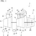
- the compressor train 1 includes a steam turbine 10 and a compression unit 20.
- the steam turbine 10 includes a rotating shaft 11, a stage 12 formed of a plurality of turbine blades Bt provided on an outer peripheral surface of the rotating shaft 11, a turbine casing 13 that covers the rotating shaft 11 and the turbine blades Bt from an outer peripheral side.
- the steam turbine 10 includes a plurality of the stages 12.
- the number of stages 12 is desirably is 13.
- nozzles are provided on an inner peripheral side of the turbine casing 13 so as to alternate with the turbine blades Bt. The high-temperature and high-pressure steam introduced into the turbine casing 13 collides with the turbine blades Bt to apply a rotational force to the rotating shaft 11.
- This rotational force is used to drive the compression unit 20 through a driving shaft 50 connected to a shaft end.
- a length of a portion of the rotating shaft 11 protruding from the turbine casing 13 is 1,000 to 1,500 mm.
- the steam turbine 10 preferably has an inlet flow rate of 1,000 to 1,200 t/h, a bleed air flow rate of 700 to 1,000 t/h, and an upper limit of a rotation rate of 4,500 rpm.
- the steam turbine 10 includes an inner bar type control valve.
- the compression unit 20 includes a low pressure compression unit LP, a high pressure compression unit HP, and the driving shaft 50.
- the low pressure compression unit LP and the high pressure compression unit HP are connected via the common driving shaft 50.
- the low pressure compression unit LP and the high pressure compression unit HP are both driven by rotating the driving shaft 50 by the steam turbine 10.
- the low pressure compression unit LP and the high pressure compression unit HP have a plurality of impellers 40 (see FIG. 2 ) and casings that cover these impellers 40 from the outside.
- the casing of the low pressure compression unit LP (low pressure casing Lc) and the casing of the high pressure compression unit HP (high pressure casing Hc) are independent of each other.
- the compressor train 1 includes only three casings in total including a turbine casing 13 of the steam turbine 10.
- the low pressure compression unit LP includes a plurality of (three) sections 21L, 22L, and 23L. Each of the sections 21L, 22L, and 23L is a part until the charge gas flows into and is discharged from the low pressure casing Lc. These sections 21L, 22L, and 23L are arranged in this order from an upstream side to a downstream side along a flow direction of the charge gas.
- the charge gas discharged from the first low pressure discharge unit E1 is sent to the adjacent second low pressure section 22L via a processing unit p1 that performs a predetermined process included in the ethylene plant with respect to the charge gas.
- the second low pressure section 22L is provided on the downstream side of the first low pressure section 21L.
- the second low pressure section 22L includes a second low pressure introduction unit S2 for introducing the charge gas supplied from the processing unit p1, and a second low pressure discharge unit E2 for discharging the charge gas further compressed in the second low pressure section 22L.
- the charge gas discharged from the second low pressure discharge unit E2 is sent to the adjacent third low pressure section 23L via a processing unit p2 that performs a predetermined process with respect to the charge gas.
- the third low pressure section 23L is provided on the downstream side of the second low pressure section 22L.
- the third low pressure section 23L includes a third low pressure introduction unit S3 for introducing the charge gas supplied from the processing unit p2, and a third low pressure discharge unit E3 for discharging the charge gas further compressed in the third low pressure section 23L.
- the charge gas discharged from the third low pressure discharge unit E3 is sent to the high pressure compression unit HP via a processing unit p3 that performs a predetermined process with respect to the charge gas.
- the high pressure compression unit HP includes a plurality of (two) sections 31H and 32H.
- Each of the sections 31H and 32H is a part until the charge gas flows into and is discharged from the high pressure casing Hc.
- These sections 31H and 32H are arranged in this order from the upstream side to the downstream side along the flow direction of the charge gas.
- the first high pressure section 31H positioned at the uppermost stream side includes a first high pressure introduction unit S4 into which the charge gas compressed by the low pressure compression unit LP is introduced, and a first high pressure discharge unit E4 for discharging the charge gas compressed in the first high pressure section 31H.
- the charge gas discharged from the first high pressure discharge unit E4 is sent to the adjacent second high pressure section 32H via a processing unit p4 that performs a predetermined process included in the ethylene plant with respect to the charge gas.
- the second high pressure section 32H is provided on the downstream side of the first high pressure section 31H.
- the second high pressure section 32H includes a second high pressure introduction unit S5 for introducing the charge gas supplied from the processing unit p4, and a second high pressure discharge unit E5 for discharging the charge gas further compressed in the second high pressure section 32H.
- the charge gas discharged from the second high pressure discharge unit E5 is sent to a processing unit p5 that performs a predetermined process with respect to the charge gas.
- the temperature of the charge gas discharged from each of the above sections 21L, 22L, 23L, 31H, and 32H is 80°C to 120°C.
- the first low pressure section 21L, the second low pressure section 22L, the third low pressure section 23L, the first high pressure section 31H, and the second high pressure section 32H have a plurality of impellers 40, respectively.
- each section has a plurality of compression stages formed by one impeller 40.
- the low pressure compression unit LP includes four compression stages and the high pressure compression unit HP includes six compression stages.
- one nozzle is provided on each of both sides of the driving shaft 50 in the extending direction. These nozzles extend so as to protrude from the low pressure casing Lc so as not to interfere with the casing (high pressure casing Hc) of the high pressure compression unit HP and the casing (turbine casing 13) of the steam turbine 10.
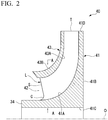
- the impeller 40 includes a disc 41, a blade 42, and a shroud 43.
- the disc 41 has a disc shape centered on a central axis (axis O) of the driving shaft 50 described above.
- the surface of the disc 41 facing one side in an axis O direction is a disc main surface 41A.
- the disc main surface 41A is curved outward in a radial direction as it goes from one side toward the other side in the axis O direction.
- a plurality of blades 42 are arranged on the disc main surface 41A. The blades 42 will be described later.
- the surface facing the side opposite to the disc main surface 41A is a disc back surface 41B.
- a surface of the disc 41 facing inward in the radial direction is a disc inner peripheral surface 41C.
- the disc inner peripheral surface 41C is in contact with an outer peripheral surface of the driving shaft 50.
- the surface of the disc 41 facing outward in the radial direction is a disc outer peripheral surface 41D.
- the plurality of blades 42 are provided on the disc main surface 41A at intervals in a circumferential direction.
- Each blade 42 extends along the disc main surface 41A from a leading edge L which is an edge on one side in the axis O direction to a trailing edge T which is an edge on the other side.
- the blade 42 extends from the inner side toward the outer side in the radial direction from the one side toward the other side in the axis O direction.
- the leading edge L has a straight portion S and a curved portion C.
- the straight portion S linearly extends towards the other side in the axis O direction, as it goes from the outer side toward the inner side in the radial direction.
- the straight portion S recedes toward the other side in the axis O direction with respect to the radial direction.
- the curved portion C is gradually curved toward the one side in the axis O direction as it goes from the inner end of the straight portion S in the radial direction toward the inner side in the radial direction. More specifically, the curved portion C has a curved shape protruding inward in the radial direction.
- an outer diameter of the blade 42 (that is, a length from the axis O to the trailing edge T in a radial direction) is 1,400 to 1,800 mm.
- a rotation rate of the driving shaft 50 is select such that a maximum operating peripheral speed of the blade 42 at an outermost diameter position is 350 to 400 m/s.
- the shroud 43 has a funnel shape that covers the plurality of blades 42 from the outer peripheral side.
- a shroud inner peripheral surface 43A which is a surface of the shroud 43 facing the inner side in the radial direction, is connected to an outer edge of the blade 42 in the radial direction.
- the shroud inner peripheral surface 43A extends from the inner side toward the outer side in the radial direction as it goes from the one side toward the other side in the axis O direction.
- a shroud outer peripheral surface 43B which is a surface of the shroud 43 facing the outer side in the radial direction, extends from the inner side to the outer side in the radial direction as it goes from one side to the other side in the axis O direction.
- a thickness of the shroud 43 on the outer side in the radial direction is larger than that of a shroud applied to a closed impeller of the related art.
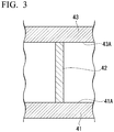
- the angle of the blade 42 with respect to the disc 41 and the shroud 43 is larger than 0° and smaller than 90°.
- each impeller 40 in each compression stage is a closed impeller, and accordingly, a leakage amount of charge gas can be reduced.
- the leakage amount of the charge gas between the shroud 43 and the inner peripheral surface of the casing may increase.
- the work amount per compression stage can be increased without increasing the number of impellers 40 or increasing the impeller diameter. As a result, it is possible to increase the capacity of the compressor train 1.
- the high pressure compression unit HP and the low pressure compression unit LP includes the plurality of sections, respectively. Accordingly, the capacities of the high pressure compression unit HP and the low pressure compression unit LP can be increased.
- the high pressure compression unit HP and the low pressure compression unit LP have the high pressure casing Hc and the low pressure casing Lc provided separately from each other, respectively.
- the charge gas compressor train 1 for an ethylene plant can be configured with only three casings in total including the turbine casing 13 of the steam turbine 10. In other words, the capacity of the compression unit 20 can be increased while suppressing the dimension of the device.
- the low pressure compression unit LP includes a larger number of sections than the high pressure compression unit HP. Accordingly, after the charge gas is sufficiently compressed in the low pressure compression unit LP, the charge gas can be further compressed in the high pressure compression unit HP. Therefore, a load required for the high pressure compression unit HP can be suppressed to be small. As a result, it is possible to reduce the dimensions of the high pressure compression unit HP.
- the steam turbine 10 is an impulse type, it is possible to ensure a large heat drop per stage in the steam turbine 10. As a result, since the number of stages can be kept small, it is possible to reduce the dimension of the steam turbine 10.
- a device X in each embodiment is understood as follows, for example.
- the steam turbine 10 is an impulse type, it is possible to ensure a large heat drop per stage in the steam turbine 10. As a result, since the number of stages can be kept small, it is possible to reduce the dimensions of the steam turbine 10.
Landscapes
- Engineering & Computer Science (AREA)
- Mechanical Engineering (AREA)
- General Engineering & Computer Science (AREA)
- Structures Of Non-Positive Displacement Pumps (AREA)
- Chemical & Material Sciences (AREA)
- Organic Chemistry (AREA)
- Physics & Mathematics (AREA)
- Thermal Sciences (AREA)
- Chemical Kinetics & Catalysis (AREA)
- General Chemical & Material Sciences (AREA)
- Oil, Petroleum & Natural Gas (AREA)
Abstract
Description
- The present disclosure relates to a charge gas compressor train for an ethylene plant.
- Priority is claimed on Japanese Patent Application No.
2019-194584, filed on October 25, 2019 - An ethylene plant is a facility for producing ethylene gas which is a raw material of a polyethylene product. In the ethylene plant, naphtha separated by distilling crude oil is used as a raw material of ethylene gas. In obtaining ethylene gas, a step of thermally decomposing the naphtha to generate a charge gas and a step of separating hydrocarbons in the charge gas according to the number of carbons are performed.
- The naphtha is thermally decomposed to produce charge gas containing hydrocarbons having a lower molecular weight. Specifically, in this step, the naphtha is allowed to flow through a hot pipe together with water vapor. The naphtha is spontaneously thermally decomposed at a high temperature and a molecular chain is broken to obtain hydrocarbons having a low molecular weight. In this state, as an example, a plurality of molecules such as ethylene, propylene, or the like are mixed in the charge gas. By distilling this charge gas in the subsequent distillation step, the molecules are separated for each carbon number. Here, the distillation step is performed based on gas-liquid equilibrium between the charge gas and the steam at a high temperature. Accordingly, it is necessary to compress and liquefy the charge gas. Therefore, the ethylene plant includes a compressor for compressing the charge gas and a driving source (for example, a steam turbine) for driving the compressor (see Published Japanese Translation No.
2018-524519 - The compressor described in Published Japanese Translation No.
2018-524519 - Here, an open impeller does not have a shroud (cover) that covers a blade. Accordingly, the amount of gas leakage tends to be larger than that of a closed impeller having the shroud. As a result, efficiency of the compressor may be deteriorated.
- In order to compensate this deterioration in efficiency, it is necessary to increase the number of impellers and increase a diameter of the impeller. As a result, a dimension of the compressor may excessively increase, which may lead to an increase in construction cost and maintenance cost.
- The present disclosure has been made to solve the above problems, and an object of the present disclosure is to provide a charge gas compressor train for an ethylene plant having a smaller size and an increased capacity.
- In order to solve the above problems, according to an aspect of the present disclosure, a charge gas compressor train for an ethylene plant is provided, the compressor including: a steam turbine; and a compression unit that is driven by the steam turbine to compress a charge gas, in which the compression unit includes a closed impeller at each impeller of a plurality of compression stages, an outer diameter of a blade of the closed impeller at least at an initial stage of the plurality of compression stages is 1,400 to 1,800 mm, a maximum operating peripheral speed of the blade of the closed impeller at the initial stage at an outermost diameter position is 350 to 400 m/s, and an output of the charge gas compressor train is 100 to 140 MW.
- According to the present disclosure, it is possible to provide a charge gas compressor train for an ethylene plant having a smaller size and an increased capacity.
-
-
FIG. 1 is a schematic view showing a configuration of a compressor train according to an embodiment of the present disclosure. -
FIG. 2 is an enlarged cross-sectional view of main parts of the compression unit according to the embodiment of the present disclosure. -
FIG. 3 is a view taken along a line A-A ofFIG. 2 . - Hereinafter, a charge gas compressor train 1 for an ethylene plant (hereinafter, referred to as a compressor train 1) according to an embodiment of the present disclosure will be described with reference to
FIGS. 1 to 3 . Thecompressor train 1 is an ethylene plant that produces an ethylene gas and is used to compress the charge gas. Thecompressor train 1 according to the present embodiment has an output of 100 to 140 MW, and thus is particularly suitably used for a large-scale ethylene plant capable of producing 3 million tons of ethylene gas per year. - An ethylene plant is a facility for producing ethylene gas which is a raw material of a polyethylene product. In the ethylene plant, naphtha separated by distilling crude oil is used as a raw material of ethylene gas. In obtaining ethylene gas, a step of thermally decomposing the naphtha to generate a charge gas and a step of separating hydrocarbons in the charge gas according to the number of carbons are performed.
- The naphtha is thermally decomposed to produce charge gas containing hydrocarbons having a lower molecular weight. Specifically, in this step, the naphtha is allowed to flow through a hot pipe together with water vapor. The naphtha is spontaneously thermally decomposed at a high temperature and a molecular chain is broken to obtain hydrocarbons having a low molecular weight. In this state, as an example, a plurality of molecules such as ethylene, propylene, or the like are mixed in the charge gas. By distilling this charge gas in the subsequent distillation step, the molecules are separated for each carbon number. Here, the distillation step is performed based on gas-liquid equilibrium between the charge gas and the steam at a high temperature. Accordingly, it is necessary to compress and liquefy the charge gas. For this reason, the ethylene plant is equipped with a
compressor train 1. - As shown in
FIG. 1 , thecompressor train 1 includes asteam turbine 10 and acompression unit 20. Thesteam turbine 10 includes arotating shaft 11, astage 12 formed of a plurality of turbine blades Bt provided on an outer peripheral surface of the rotatingshaft 11, aturbine casing 13 that covers therotating shaft 11 and the turbine blades Bt from an outer peripheral side. Thesteam turbine 10 includes a plurality of thestages 12. The number ofstages 12 is desirably is 13. In addition, although not shown in detail, nozzles (turbine vanes) are provided on an inner peripheral side of theturbine casing 13 so as to alternate with the turbine blades Bt. The high-temperature and high-pressure steam introduced into theturbine casing 13 collides with the turbine blades Bt to apply a rotational force to the rotatingshaft 11. - This rotational force is used to drive the
compression unit 20 through adriving shaft 50 connected to a shaft end. - In addition, a length of a portion of the rotating
shaft 11 protruding from theturbine casing 13 is 1,000 to 1,500 mm. - The
steam turbine 10 preferably has an inlet flow rate of 1,000 to 1,200 t/h, a bleed air flow rate of 700 to 1,000 t/h, and an upper limit of a rotation rate of 4,500 rpm. In addition, thesteam turbine 10 includes an inner bar type control valve. - The
compression unit 20 includes a low pressure compression unit LP, a high pressure compression unit HP, and thedriving shaft 50. - The low pressure compression unit LP and the high pressure compression unit HP are connected via the
common driving shaft 50. In other words, the low pressure compression unit LP and the high pressure compression unit HP are both driven by rotating thedriving shaft 50 by thesteam turbine 10. - As will be described later in detail, the low pressure compression unit LP and the high pressure compression unit HP have a plurality of impellers 40 (see
FIG. 2 ) and casings that cover theseimpellers 40 from the outside. The casing of the low pressure compression unit LP (low pressure casing Lc) and the casing of the high pressure compression unit HP (high pressure casing Hc) are independent of each other. In other words, thecompressor train 1 includes only three casings in total including aturbine casing 13 of thesteam turbine 10. - The low pressure compression unit LP includes a plurality of (three)
sections sections sections - In the first
low pressure section 21L positioned at the uppermost stream side, a first low pressure introduction unit S1 into which the charge gas generated in the preceding process in the ethylene plant is introduced, and a first low pressure discharge unit E1 which discharges the charge gas compressed in the firstlow pressure section 21L. The charge gas discharged from the first low pressure discharge unit E1 is sent to the adjacent secondlow pressure section 22L via a processing unit p1 that performs a predetermined process included in the ethylene plant with respect to the charge gas. - The second
low pressure section 22L is provided on the downstream side of the firstlow pressure section 21L. The secondlow pressure section 22L includes a second low pressure introduction unit S2 for introducing the charge gas supplied from the processing unit p1, and a second low pressure discharge unit E2 for discharging the charge gas further compressed in the secondlow pressure section 22L. The charge gas discharged from the second low pressure discharge unit E2 is sent to the adjacent thirdlow pressure section 23L via a processing unit p2 that performs a predetermined process with respect to the charge gas. - The third
low pressure section 23L is provided on the downstream side of the secondlow pressure section 22L. The thirdlow pressure section 23L includes a third low pressure introduction unit S3 for introducing the charge gas supplied from the processing unit p2, and a third low pressure discharge unit E3 for discharging the charge gas further compressed in the thirdlow pressure section 23L. The charge gas discharged from the third low pressure discharge unit E3 is sent to the high pressure compression unit HP via a processing unit p3 that performs a predetermined process with respect to the charge gas. - In a similar manner as the low pressure compression unit LP, the high pressure compression unit HP includes a plurality of (two)
sections sections sections - The first
high pressure section 31H positioned at the uppermost stream side includes a first high pressure introduction unit S4 into which the charge gas compressed by the low pressure compression unit LP is introduced, and a first high pressure discharge unit E4 for discharging the charge gas compressed in the firsthigh pressure section 31H. The charge gas discharged from the first high pressure discharge unit E4 is sent to the adjacent secondhigh pressure section 32H via a processing unit p4 that performs a predetermined process included in the ethylene plant with respect to the charge gas. - The second
high pressure section 32H is provided on the downstream side of the firsthigh pressure section 31H. The secondhigh pressure section 32H includes a second high pressure introduction unit S5 for introducing the charge gas supplied from the processing unit p4, and a second high pressure discharge unit E5 for discharging the charge gas further compressed in the secondhigh pressure section 32H. The charge gas discharged from the second high pressure discharge unit E5 is sent to a processing unit p5 that performs a predetermined process with respect to the charge gas. The temperature of the charge gas discharged from each of theabove sections - The first
low pressure section 21L, the secondlow pressure section 22L, the thirdlow pressure section 23L, the firsthigh pressure section 31H, and the secondhigh pressure section 32H have a plurality ofimpellers 40, respectively. In other words, each section has a plurality of compression stages formed by oneimpeller 40. As an example, in thecompressor train 1 according to the present embodiment, the low pressure compression unit LP includes four compression stages and the high pressure compression unit HP includes six compression stages. - In addition, although not shown in detail, in the casing of the low pressure compression unit LP (low pressure casing Lc), one nozzle is provided on each of both sides of the driving
shaft 50 in the extending direction. These nozzles extend so as to protrude from the low pressure casing Lc so as not to interfere with the casing (high pressure casing Hc) of the high pressure compression unit HP and the casing (turbine casing 13) of thesteam turbine 10. - Next, the configuration of the
impeller 40 will be described with reference toFIGS. 2 and3 . As shown inFIG. 2 , theimpeller 40 includes adisc 41, ablade 42, and ashroud 43. Thedisc 41 has a disc shape centered on a central axis (axis O) of the drivingshaft 50 described above. The surface of thedisc 41 facing one side in an axis O direction is a discmain surface 41A. The discmain surface 41A is curved outward in a radial direction as it goes from one side toward the other side in the axis O direction. A plurality ofblades 42 are arranged on the discmain surface 41A. Theblades 42 will be described later. The surface facing the side opposite to the discmain surface 41A is a disc backsurface 41B. A surface of thedisc 41 facing inward in the radial direction is a disc inner peripheral surface 41C. The disc inner peripheral surface 41C is in contact with an outer peripheral surface of the drivingshaft 50. The surface of thedisc 41 facing outward in the radial direction is a disc outerperipheral surface 41D. - The plurality of
blades 42 are provided on the discmain surface 41A at intervals in a circumferential direction. Eachblade 42 extends along the discmain surface 41A from a leading edge L which is an edge on one side in the axis O direction to a trailing edge T which is an edge on the other side. In other words, theblade 42 extends from the inner side toward the outer side in the radial direction from the one side toward the other side in the axis O direction. - The leading edge L has a straight portion S and a curved portion C. The straight portion S linearly extends towards the other side in the axis O direction, as it goes from the outer side toward the inner side in the radial direction. In other words, the straight portion S recedes toward the other side in the axis O direction with respect to the radial direction. The curved portion C is gradually curved toward the one side in the axis O direction as it goes from the inner end of the straight portion S in the radial direction toward the inner side in the radial direction. More specifically, the curved portion C has a curved shape protruding inward in the radial direction.
- In the initial stage (that is, the
first stage impeller 40 in the firstlow pressure section 21L) of the low pressure compression unit LP, an outer diameter of the blade 42 (that is, a length from the axis O to the trailing edge T in a radial direction) is 1,400 to 1,800 mm. In addition, a rotation rate of the drivingshaft 50 is select such that a maximum operating peripheral speed of theblade 42 at an outermost diameter position is 350 to 400 m/s. - The
shroud 43 has a funnel shape that covers the plurality ofblades 42 from the outer peripheral side. - A shroud inner
peripheral surface 43A, which is a surface of theshroud 43 facing the inner side in the radial direction, is connected to an outer edge of theblade 42 in the radial direction. The shroud innerperipheral surface 43A extends from the inner side toward the outer side in the radial direction as it goes from the one side toward the other side in the axis O direction. In the same manner as the shroud innerperipheral surface 43A, a shroud outerperipheral surface 43B, which is a surface of theshroud 43 facing the outer side in the radial direction, extends from the inner side to the outer side in the radial direction as it goes from one side to the other side in the axis O direction. In the present embodiment, a thickness of theshroud 43 on the outer side in the radial direction is larger than that of a shroud applied to a closed impeller of the related art. The angle of theblade 42 with respect to thedisc 41 and theshroud 43 is larger than 0° and smaller than 90°. - By using such a configuration of the
blade 42, it is possible to sufficiently resist against the stress applied to theblade 42, even when theimpeller 40 is rotated at a high peripheral speed (350 to 400 m/s) as described above. - In addition, according to the configuration described above, each
impeller 40 in each compression stage is a closed impeller, and accordingly, a leakage amount of charge gas can be reduced. On the other hand, as compared to a case where theimpeller 40 does not have the shroud 43 (that is, the case where theimpeller 40 is an open impeller), the leakage amount of the charge gas between theshroud 43 and the inner peripheral surface of the casing may increase. However, in the structure according to the present embodiment, it is possible to reduce the possibility of such leakage. Therefore, the work amount per compression stage can be increased without increasing the number ofimpellers 40 or increasing the impeller diameter. As a result, it is possible to increase the capacity of thecompressor train 1. - According to the configuration described above, since a temperature of the charge gas discharged from each of the
sections impeller 40 as a closed impeller rather than an open impeller, the fouling is less likely to directly collide with theblade 42. As a result, it is possible to reduce the possibility of a damage or wear on theblade 42. - According to the configuration described above, the high pressure compression unit HP and the low pressure compression unit LP includes the plurality of sections, respectively. Accordingly, the capacities of the high pressure compression unit HP and the low pressure compression unit LP can be increased. In addition, the high pressure compression unit HP and the low pressure compression unit LP have the high pressure casing Hc and the low pressure casing Lc provided separately from each other, respectively. Accordingly, the charge
gas compressor train 1 for an ethylene plant can be configured with only three casings in total including theturbine casing 13 of thesteam turbine 10. In other words, the capacity of thecompression unit 20 can be increased while suppressing the dimension of the device. - According to the configuration described above, the low pressure compression unit LP includes a larger number of sections than the high pressure compression unit HP. Accordingly, after the charge gas is sufficiently compressed in the low pressure compression unit LP, the charge gas can be further compressed in the high pressure compression unit HP. Therefore, a load required for the high pressure compression unit HP can be suppressed to be small. As a result, it is possible to reduce the dimensions of the high pressure compression unit HP.
- According to the configuration described above, since the
steam turbine 10 is an impulse type, it is possible to ensure a large heat drop per stage in thesteam turbine 10. As a result, since the number of stages can be kept small, it is possible to reduce the dimension of thesteam turbine 10. - As described above, the embodiment of the present disclosure has been described in detail with reference to the drawings, but the specific configuration is not limited to this embodiment and may include design changes and the like without departing from the scope of the present disclosure.
- A device X in each embodiment is understood as follows, for example.
- (1) The charge
gas compressor train 1 for an ethylene plant according to a first aspect includes: thesteam turbine 10; and thecompression unit 20 that is driven by thesteam turbine 10 to compress a charge gas, thecompression unit 20 includes aclosed impeller 40 at each impeller of a plurality of compression stages, an outer diameter of theblade 42 of theclosed impeller 40 at least at an initial stage of the plurality of compression stages is 1,400 to 1,800 mm, a maximum operating peripheral speed of theblade 42 of theclosed impeller 40 at the initial stage at an outermost diameter position is 350 to 400 m/s, and an output of the charge gas compressor train is 100 to 140 MW.
According to the configuration described above, eachimpeller 40 at each compression stage is a closed impeller, and accordingly, it is possible to reduce the leakage amount of the charge gas. Therefore, the work amount per compression stage can be increased without increasing the number ofimpellers 40 or increasing the impeller diameter. - (2) In the charge
gas compressor train 1 for an ethylene plant according to a second aspect, thecompression unit 20 includes a plurality of sections, each of the plurality of sections is a part until the charge gas flows into and is discharged from thecompression unit 20, and a temperature of the charge gas discharged from each section is 80°C to 120°C.
According to the configuration described above, since the temperature of the charge gas discharged from each section is 80°C to 120°C, the fouling is likely to occur in the charge gas. However, since each compression stage has a closed impeller, rather than an open impeller, the fouling is less likely to collide directly with theblade 42. As a result, it is possible to reduce the possibility of a damage or wear on theblade 42. - (3) In the charge
gas compressor train 1 for an ethylene plant according to a third aspect, thecompression unit 20 includes the high pressure compression unit HP having the high pressure casing Hc, and the low pressure compression unit LP having the low pressure casing Lc provided separately from the high pressure casing Hc, and the high pressure compression unit HP and the low pressure compression unit LP include the plurality of sections, respectively.
According to the configuration described above, the high pressure compression unit HP and the low pressure compression unit LP includes the plurality of sections, respectively. Accordingly, the capacities of the high pressure compression unit HP and the low pressure compression unit LP can be increased. In addition, the high pressure compression unit HP and the low pressure compression unit LP have the high pressure casing Hc and the low pressure casing Lc provided separately from each other, respectively. Therefore, the chargegas compressor train 1 for an ethylene plant can be configured with only three casings in total including the casing (the turbine casing 13) of thesteam turbine 10. In other words, the capacity of thecompression unit 20 can be increased while suppressing the dimension of the device. - (4) In the charge
gas compressor train 1 for an ethylene plant according to a fourth aspect, the low pressure compression unit LP includes a larger number of sections than the high pressure compression unit HP.
According to the configuration described above, the low pressure compression unit LP includes a larger number of sections than the high pressure compression unit HP. Accordingly, after the charge gas is sufficiently compressed in the low pressure compression unit LP, the charge gas can be further compressed in the high pressure compression unit HP. Therefore, a load required for the high pressure compression unit HP can be suppressed to be small. As a result, it is possible to reduce the dimensions of thecompression unit 20. - (5) In the charge
gas compressor train 1 for an ethylene plant according to a fifth aspect, thesteam turbine 10 includes arotating shaft 11 connected to the same shaft of thecompression unit 20, and the plurality ofstages 12 formed of the plurality of turbine blades Bt arranged on the outer peripheral surface of therotating shaft 11, and thesteam turbine 10 is an impulse type in which the steam introduced from the outside at eachstage 12 collides with the turbine blades Bt to apply a rotational force to therotating shaft 11. - According to the configuration described above, since the
steam turbine 10 is an impulse type, it is possible to ensure a large heat drop per stage in thesteam turbine 10. As a result, since the number of stages can be kept small, it is possible to reduce the dimensions of thesteam turbine 10. -
- 1 Charge gas compressor train for ethylene plant (compressor train)
- 10 Steam turbine
- 11 Rotating shaft
- 12 Stage
- 13 Turbine casing
- 20 Compression unit
- 21L First low pressure section
- 22L Second low pressure section
- 23L Third low pressure section
- 31H First high pressure section
- 32H Second high pressure section
- 40 Impeller
- 41 Disc
- 41A Disc main surface
- 41B Disc back surface
- 41C Disc inner peripheral surface
- 41D Disc outer peripheral surface
- 42 blade
- L leading edge
- S Straight portion
- C Curved portion
- T Trailing edge
- 43 Shroud
- 43A Shroud inner peripheral surface
- 43B Shroud outer peripheral surface
- 50 Driving shaft
- S1 First low pressure introduction unit
- S2 Second low pressure introduction unit
- S3 Third low pressure introduction unit
- S4 First high pressure introduction unit
- S5 Second high pressure introduction unit
- E1 First low pressure discharge unit
- E2 Second low pressure discharge unit
- E3 Third low pressure discharge unit
- E4 First high pressure discharge unit
- E5 Second high pressure discharge unit
- Hc High pressure casing
- Lc Low pressure casing
- O axis
- p1, p2, p3, p4, p5 Processing unit
Claims (5)
- A charge gas compressor train for an ethylene plant, the compressor comprising:a steam turbine; anda compression unit that is configured to drive by the steam turbine to compress a charge gas,wherein the compression unit includes a closed impeller at each impeller of a plurality of compression stages,an outer diameter of the blade of the closed impeller at least at an initial stage of the plurality of compression stages is 1,400 to 1,800 mm,a maximum operating peripheral speed of the blade of the closed impeller at the initial stage at an outermost diameter position is 350 to 400 m/s, andan output of the charge gas compressor train is 100 to 140 MW.
- The charge gas compressor train for an ethylene plant according to claim 1,wherein the compression unit includes a plurality of sections, each of the plurality of sections is a part until the charge gas flows into and is discharged from the compression unit, anda temperature of the charge gas discharged from each section is 80°C to 120°C.
- The charge gas compressor train for an ethylene plant according to claim 2,wherein the compression unit includes a high pressure compression unit having a high pressure casing, and a low pressure compression unit having a low pressure casing provided separately from the high pressure casing, andthe high pressure compression unit and the low pressure compression unit include the plurality of sections, respectively.
- The charge gas compressor train for an ethylene plant according to claim 3,
wherein the low pressure compression unit includes a larger number of sections than the high pressure compression unit. - The charge gas compressor train for an ethylene plant according to any one of claims 1 to 4,wherein the steam turbine includes a rotating shaft connected to the same shaft of the compression unit, and a plurality of stages formed of a plurality of turbine blades arranged on an outer peripheral surface of the rotating shaft, andthe steam turbine is an impulse type in which the steam introduced from the outside at each stage collides with the turbine blades to apply a rotational force to the rotating shaft.
Applications Claiming Priority (1)
| Application Number | Priority Date | Filing Date | Title |
|---|---|---|---|
| JP2019194584A JP7341854B2 (en) | 2019-10-25 | 2019-10-25 | Charge gas compressor train for ethylene plant |
Publications (1)
| Publication Number | Publication Date |
|---|---|
| EP3812597A1 true EP3812597A1 (en) | 2021-04-28 |
Family
ID=73014334
Family Applications (1)
| Application Number | Title | Priority Date | Filing Date |
|---|---|---|---|
| EP20203639.8A Ceased EP3812597A1 (en) | 2019-10-25 | 2020-10-23 | Charge gas compressor train for ethylene plant |
Country Status (3)
| Country | Link |
|---|---|
| US (1) | US11506209B2 (en) |
| EP (1) | EP3812597A1 (en) |
| JP (1) | JP7341854B2 (en) |
Cited By (1)
| Publication number | Priority date | Publication date | Assignee | Title |
|---|---|---|---|---|
| US20210123446A1 (en) * | 2019-10-25 | 2021-04-29 | Mitsubishi Heavy Industries Compressor Corporation | Charge gas compressor train for ethylene plant |
Families Citing this family (1)
| Publication number | Priority date | Publication date | Assignee | Title |
|---|---|---|---|---|
| JP2024093441A (en) * | 2022-12-27 | 2024-07-09 | 三菱重工コンプレッサ株式会社 | Impeller and centrifugal compressor |
Citations (5)
| Publication number | Priority date | Publication date | Assignee | Title |
|---|---|---|---|---|
| JP2010127245A (en) * | 2008-11-28 | 2010-06-10 | Mitsubishi Heavy Ind Ltd | Centrifugal compressor |
| US20180209728A1 (en) * | 2017-01-24 | 2018-07-26 | Nuovo Pignone Tecnologie - S.R.L. | Compression train including one centrifugal compressor and lng plant |
| US20180238236A1 (en) * | 2015-07-24 | 2018-08-23 | Nuovo Pignone Technologie Srl | Charge gas compression train for ethylene |
| WO2018206102A1 (en) * | 2017-05-10 | 2018-11-15 | Nuovo Pignone Tecnologie S.r.l. | Compressor train arrangements |
| JP2019194584A (en) | 2013-12-12 | 2019-11-07 | エムイーエス メディカル エレクトロニック システムズ リミテッド | Household inspection device |
Family Cites Families (7)
| Publication number | Priority date | Publication date | Assignee | Title |
|---|---|---|---|---|
| JP2000274202A (en) | 1999-03-23 | 2000-10-03 | Toshiba Corp | Fluid machinery |
| JP2003293988A (en) | 2002-04-01 | 2003-10-15 | Mitsubishi Heavy Ind Ltd | Multi-stage rotor and centrifugal compressor with the rotor |
| JP2008169244A (en) | 2007-01-09 | 2008-07-24 | Jgc Corp | Natural gas processing method |
| CN107061311A (en) * | 2017-05-16 | 2017-08-18 | 沈阳斯特机械制造有限公司 | Heavy-oil catalytic olefin hydrocarbon apparatus centrifugal compressor |
| JP6995719B2 (en) * | 2018-09-04 | 2022-01-17 | 株式会社日立インダストリアルプロダクツ | Centrifugal impeller and centrifugal fluid machine |
| JP7341854B2 (en) * | 2019-10-25 | 2023-09-11 | 三菱重工コンプレッサ株式会社 | Charge gas compressor train for ethylene plant |
| JP7333247B2 (en) * | 2019-11-01 | 2023-08-24 | 三菱重工コンプレッサ株式会社 | Ammonia plant synthesis gas compressor train |
-
2019
- 2019-10-25 JP JP2019194584A patent/JP7341854B2/en active Active
-
2020
- 2020-10-23 US US17/078,505 patent/US11506209B2/en active Active
- 2020-10-23 EP EP20203639.8A patent/EP3812597A1/en not_active Ceased
Patent Citations (6)
| Publication number | Priority date | Publication date | Assignee | Title |
|---|---|---|---|---|
| JP2010127245A (en) * | 2008-11-28 | 2010-06-10 | Mitsubishi Heavy Ind Ltd | Centrifugal compressor |
| JP2019194584A (en) | 2013-12-12 | 2019-11-07 | エムイーエス メディカル エレクトロニック システムズ リミテッド | Household inspection device |
| US20180238236A1 (en) * | 2015-07-24 | 2018-08-23 | Nuovo Pignone Technologie Srl | Charge gas compression train for ethylene |
| JP2018524519A (en) * | 2015-07-24 | 2018-08-30 | ヌオーヴォ・ピニォーネ・テクノロジー・ソチエタ・レスポンサビリタ・リミタータNuovo Pignone Tecnologie S.R.L. | Charge gas compression train for ethylene |
| US20180209728A1 (en) * | 2017-01-24 | 2018-07-26 | Nuovo Pignone Tecnologie - S.R.L. | Compression train including one centrifugal compressor and lng plant |
| WO2018206102A1 (en) * | 2017-05-10 | 2018-11-15 | Nuovo Pignone Tecnologie S.r.l. | Compressor train arrangements |
Cited By (2)
| Publication number | Priority date | Publication date | Assignee | Title |
|---|---|---|---|---|
| US20210123446A1 (en) * | 2019-10-25 | 2021-04-29 | Mitsubishi Heavy Industries Compressor Corporation | Charge gas compressor train for ethylene plant |
| US11506209B2 (en) * | 2019-10-25 | 2022-11-22 | Mitsubishi Heavy Industries Compressor Corporation | Charge gas compressor train for ethylene plant |
Also Published As
| Publication number | Publication date |
|---|---|
| US11506209B2 (en) | 2022-11-22 |
| JP7341854B2 (en) | 2023-09-11 |
| JP2021067244A (en) | 2021-04-30 |
| US20210123446A1 (en) | 2021-04-29 |
Similar Documents
| Publication | Publication Date | Title |
|---|---|---|
| EP2324292B1 (en) | Canted outlet for a transition duct in a gas turbine engine | |
| EP2324224B1 (en) | Transition with a linear flow path with exhaust mouths for use in a gas turbine engine | |
| EP2948641B1 (en) | Seal assembly in a gas turbine engine including grooves in a radially outwardly facing side of a platform and in a inwardly facing side of an inner shroud | |
| US11273423B2 (en) | Turbomachine type chemical reactor | |
| JP5331715B2 (en) | Gas turbine, exhaust diffuser, and gas turbine plant modification method | |
| EP2948639B1 (en) | Seal assembly including grooves in an inner shroud in a gas turbine engine | |
| US11788546B2 (en) | Ammonia plant synthesis gas compressor train | |
| US11506209B2 (en) | Charge gas compressor train for ethylene plant | |
| EP2418352B1 (en) | Gas turbine engine comprising a compressor with longitudinal cooling passages | |
| CN102003274A (en) | Turbine, and turbocharger provided with the same | |
| US20120134797A1 (en) | Multi-stage radial turbine | |
| CN103032345A (en) | Supersonic compressor | |
| US8152448B2 (en) | Steam turbine having a nozzle box arranged at an upstream side of a steam passage that divides a space between a rotor and a casing into spaces that are sealed from each other | |
| EP2778375A2 (en) | Axial-flow turbine and power plant including the same | |
| EP3325794B1 (en) | Charge gas compression train for ethylene | |
| JP5583493B2 (en) | Method and apparatus for assembling a rotating machine | |
| US20050025614A1 (en) | Turbine engine and a method for cooling a turbine engine | |
| EP2899369B1 (en) | Multistage axial flow compressor | |
| US20130058776A1 (en) | Aerodynamic coupling between two annular rows of stationary vanes in a turbine engine | |
| US11702962B2 (en) | Steam turbine configured to recover static pressure of steam in diffuser | |
| JP2011117344A (en) | Radial turbine and supercharger | |
| CN103422905B (en) | Turbine and for reducing the method for impact loss of turbine | |
| AU2020268493B2 (en) | Stator blade for a centrifugal compressor | |
| EP3653839A1 (en) | Turbine aerofoil | |
| RU2012124190A (en) | MULTI-STAGE TURBO MACHINE |
Legal Events
| Date | Code | Title | Description |
|---|---|---|---|
| PUAI | Public reference made under article 153(3) epc to a published international application that has entered the european phase |
Free format text: ORIGINAL CODE: 0009012 |
|
| STAA | Information on the status of an ep patent application or granted ep patent |
Free format text: STATUS: THE APPLICATION HAS BEEN PUBLISHED |
|
| AK | Designated contracting states |
Kind code of ref document: A1 Designated state(s): AL AT BE BG CH CY CZ DE DK EE ES FI FR GB GR HR HU IE IS IT LI LT LU LV MC MK MT NL NO PL PT RO RS SE SI SK SM TR |
|
| AX | Request for extension of the european patent |
Extension state: BA ME |
|
| STAA | Information on the status of an ep patent application or granted ep patent |
Free format text: STATUS: REQUEST FOR EXAMINATION WAS MADE |
|
| 17P | Request for examination filed |
Effective date: 20210923 |
|
| RBV | Designated contracting states (corrected) |
Designated state(s): AL AT BE BG CH CY CZ DE DK EE ES FI FR GB GR HR HU IE IS IT LI LT LU LV MC MK MT NL NO PL PT RO RS SE SI SK SM TR |
|
| STAA | Information on the status of an ep patent application or granted ep patent |
Free format text: STATUS: EXAMINATION IS IN PROGRESS |
|
| 17Q | First examination report despatched |
Effective date: 20211201 |
|
| STAA | Information on the status of an ep patent application or granted ep patent |
Free format text: STATUS: THE APPLICATION HAS BEEN REFUSED |
|
| 18R | Application refused |
Effective date: 20240926 |