EP3812526A1 - A perforated brace band connector and a brace band system - Google Patents
A perforated brace band connector and a brace band system Download PDFInfo
- Publication number
- EP3812526A1 EP3812526A1 EP19204391.7A EP19204391A EP3812526A1 EP 3812526 A1 EP3812526 A1 EP 3812526A1 EP 19204391 A EP19204391 A EP 19204391A EP 3812526 A1 EP3812526 A1 EP 3812526A1
- Authority
- EP
- European Patent Office
- Prior art keywords
- end portion
- brace band
- perforated
- connector according
- perforated brace
- Prior art date
- Legal status (The legal status is an assumption and is not a legal conclusion. Google has not performed a legal analysis and makes no representation as to the accuracy of the status listed.)
- Withdrawn
Links
Images



Classifications
-
- F—MECHANICAL ENGINEERING; LIGHTING; HEATING; WEAPONS; BLASTING
- F16—ENGINEERING ELEMENTS AND UNITS; GENERAL MEASURES FOR PRODUCING AND MAINTAINING EFFECTIVE FUNCTIONING OF MACHINES OR INSTALLATIONS; THERMAL INSULATION IN GENERAL
- F16B—DEVICES FOR FASTENING OR SECURING CONSTRUCTIONAL ELEMENTS OR MACHINE PARTS TOGETHER, e.g. NAILS, BOLTS, CIRCLIPS, CLAMPS, CLIPS OR WEDGES; JOINTS OR JOINTING
- F16B5/00—Joining sheets or plates, e.g. panels, to one another or to strips or bars parallel to them
- F16B5/0004—Joining sheets, plates or panels in abutting relationship
- F16B5/008—Joining sheets, plates or panels in abutting relationship by a rotating or sliding and rotating movement
-
- F—MECHANICAL ENGINEERING; LIGHTING; HEATING; WEAPONS; BLASTING
- F16—ENGINEERING ELEMENTS AND UNITS; GENERAL MEASURES FOR PRODUCING AND MAINTAINING EFFECTIVE FUNCTIONING OF MACHINES OR INSTALLATIONS; THERMAL INSULATION IN GENERAL
- F16B—DEVICES FOR FASTENING OR SECURING CONSTRUCTIONAL ELEMENTS OR MACHINE PARTS TOGETHER, e.g. NAILS, BOLTS, CIRCLIPS, CLAMPS, CLIPS OR WEDGES; JOINTS OR JOINTING
- F16B5/00—Joining sheets or plates, e.g. panels, to one another or to strips or bars parallel to them
- F16B5/04—Joining sheets or plates, e.g. panels, to one another or to strips or bars parallel to them by means of riveting
-
- F—MECHANICAL ENGINEERING; LIGHTING; HEATING; WEAPONS; BLASTING
- F16—ENGINEERING ELEMENTS AND UNITS; GENERAL MEASURES FOR PRODUCING AND MAINTAINING EFFECTIVE FUNCTIONING OF MACHINES OR INSTALLATIONS; THERMAL INSULATION IN GENERAL
- F16B—DEVICES FOR FASTENING OR SECURING CONSTRUCTIONAL ELEMENTS OR MACHINE PARTS TOGETHER, e.g. NAILS, BOLTS, CIRCLIPS, CLAMPS, CLIPS OR WEDGES; JOINTS OR JOINTING
- F16B7/00—Connections of rods or tubes, e.g. of non-circular section, mutually, including resilient connections
- F16B7/06—Turnbuckles
-
- E—FIXED CONSTRUCTIONS
- E04—BUILDING
- E04B—GENERAL BUILDING CONSTRUCTIONS; WALLS, e.g. PARTITIONS; ROOFS; FLOORS; CEILINGS; INSULATION OR OTHER PROTECTION OF BUILDINGS
- E04B1/00—Constructions in general; Structures which are not restricted either to walls, e.g. partitions, or floors or ceilings or roofs
- E04B1/18—Structures comprising elongated load-supporting parts, e.g. columns, girders, skeletons
- E04B1/26—Structures comprising elongated load-supporting parts, e.g. columns, girders, skeletons the supporting parts consisting of wood
- E04B2001/2696—Shear bracing
-
- E—FIXED CONSTRUCTIONS
- E04—BUILDING
- E04C—STRUCTURAL ELEMENTS; BUILDING MATERIALS
- E04C3/00—Structural elongated elements designed for load-supporting
- E04C3/02—Joists; Girders, trusses, or trusslike structures, e.g. prefabricated; Lintels; Transoms; Braces
- E04C2003/026—Braces
Definitions
- bracing systems are used to strengthen and reinforce buildings and other structural frameworks, so as to withstand lateral forces when exposed to extreme wind and/or seismic activity.
- bracing systems are commonly used for timber frame structures and roof trusses, but also for steel frame structures.
- FIG 1 illustrates wind bracing applied to a timber-framed roof (i.e. a roof truss).
- a typical wind brace band system 10 may comprise perforated bracing bands 12 or straps that are installed diagonally across a number of roof trusses 14 or rafters.
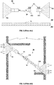
- FIG 2 A more detailed example of a known wind brace band system 10 is illustrated in Figure 2 , comprising two end brackets 16a, 16b for attachment to the truss 14, at least one perforated brace band 18, at least one tensioner 20 and a first and a second attachment plate 22a and 22b (including nuts and bolts 24).
- the perforated brace band 18 is coupled to the attachment plates 22a, 22b using a plurality of bolts and nuts 24 that are inserted through respective holes of the attachment plates 22a, 22b and the perforated brace band 18, while the tensioner 20 is at its maximum extension.
- the end brackets 16a, 16b are then mounted to respective sections of the roof trusses 14 (i.e. diagonally across) and the assembly is tensioned to a predetermined force via the tensioner 20.
- Figure 3 illustrates the assembled wind brace band system 10 installed diagonally to roof trusses 14.
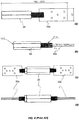
- Figures 4 (a) and (b) illustrates top view and side view of a coupling between the tensioner 20 and two attachment plates 22a spaced apart so as to allow an end portion of the perforated band 18 to slide in between the two attachment plates and fixed with the bolts and nuts 24.
- Figure 4 (c) and (d) illustrates a top view and a side view of the coupling provided on either side of the tensioner 20 allowing end portions of the perforated brace band 18 to be connected to respective attachment plates 22a on both sides of the tensioner 20.
- the connector of the present invention allows a perforated brace band to be simply guided through the stepped aperture and securely "hooked" into opposing pins or rivets.
- the opposing pin(s) or rivet(s) separated by the apertured step portion provides the advantage of a particularly simple but secure connection, because the engaged end portion of the levered brace band is synchronously and lockingly forced into opposing and counteractive pins, when moved (i.e.
- a second connector may be attached to the other end of the perforated brace band which is "levered” into the opposite direction to the first brace band end, so that are counter actively engaged with respective connectors.
- said first end portion and/or said second end portion may further comprise at least one second-type rivet operably coupled to and projecting away from respective one of said upper surface and said lower surface of said plate member, and configured to couplingly and retainingly engage with perforations of respective first and second portion of the perforated brace band.
- said at least one second-type rivet may be made from a resilient material adapted to provide a retaining interference fit with respective perforations of the perforated brace band. This provides the advantage that the perforated brace band is held in coupling engagement while the brace band system can be tightened, i.e. the brace band ends is prevented from disengaging with the pin(s) or rivet(s) of the connector.
- said resilient material may be a polymer.
- the perforated brace band is held in coupling engagement while the brace band system can be tightened, i.e. the brace band ends is prevented from disengaging with the pin(s) or rivet(s) of the connector.
- the second-type pin or rivet is configured to "wedge" into one of the holes of the perforated brace band preventing the first-type pin(s) or rivet(s) (e.g. made from metal) from sliding out of respective holes of the perforated brace band when in an untensioned state.
- the step portion 112 parallelly offsets the first 108 and second 110 end portions in a direction normal to any one of the upper 104 or lower 106 surface by a distance that is suitable to accommodate for the operably engaging perforated brace band 200, i.e. relative to the thickness of the perforated brace band 200.
- the distance between the lower surface 106 and the offset upper surface 104 is such that the perforated brace band 200 is able to operably engage with the rigid pins 114 and resilient pin 116 of the first end portion 108 and the rigid pins 114 and resilient pin 116 of the second end portion 110, while aligning substantially parallel with the upper 104 and lower 106 surface of the plate structure 102 (see, for example, Figure 7(b) ).
- the plate structure 102 and the substantially rigid pins 114 may be made from a metal or metal alloy, wherein the substantially resilient pin or rivet may be made from a polymer, such as, for example, a resiliently malleable plastic material suitable to provide a temporarily retaining interference fit with a respective hole of the perforated brace band 200.
- the metal pins 114 may be permanently attached to the plate structure 102 (e.g. glued, soldered, welded, or even as integral part of the plate structure 102 by pressing the pin out of the plate structure 102).
- the first end portion 108 may be shorter in length than the second end portion 110 for this particular example embodiment.
- the first end portion 108 and the second end portion 110 may be of any suitable length and may comprise any number and pattern of metal pins 114 and plastic rivets or pins 116 appropriate for a particular bracing system and/or a particular perforated brace band.
- a wind brace band system 300 typically includes a perforated brace band 200 having suitably patterned holes 202 fitting onto and matching the pattern of the pins and/or rivets 114, 116 provided on the connector 100.
- a perforated brace band 200 is pushed through the aperture 124 of the step portion 112 at an angle relative to the upper 104 and/or lower 106 surface of the plate structure (i.e. so as not to interfere with the pins or rivets 114, 116).
- FIG. 8 illustrates the tightening of the wind brace band system 300 by rotating the tensioner 400 (direction of arrow) and reducing the distance between the end brackets 302a and 302b of the wind brace band system 300 (arrows indicate direction of pull).
- FIG. 8 (c) A portion of an alternative wind brace band system 500 is shown in Figure 8 (c) , comprising, inter alia, two perforated brace bands 200, coupled to a central tensioner 400 via respective connectors 100.
- the connector 100 of the present invention may be coupled to the tensioner 400 and/or end brackets 302a, 302b, via mount 122.
- the mount 122 is an aperture configured to receive a bolt 304 so as to movably couple the connector 100 to the end bracket 302a, 302b and/or tensioner 400.
- the coupling 122, 304 is configured to allow relative movement between the connector 100 and respective one of the end bracket 302a, 302b or tensioner 400 .
- Figure 9 shows an alternative design of the plate structure 102 of the connector 100 of the present invention, i.e. having a narrowed mid-section.
- the plate structure 102 may have any suitable shape, any number and pattern of pins or rivets 114, 116, as well as, any suitable mount 122 for coupling the connector 100 to an external component.
Landscapes
- Engineering & Computer Science (AREA)
- General Engineering & Computer Science (AREA)
- Mechanical Engineering (AREA)
- Joining Of Building Structures In Genera (AREA)
Abstract
The present invention provides for a connector for anchoring perforated brace bands, comprising a plate member, having an upper surface and a lower surface opposing said upper surface, said pate member further comprising a first end portion, comprising at least one first-type rivet, operably coupled to and projecting away from said upper surface and configured to couplingly engage with perforations of a first portion of a perforated brace band; a second end portion, opposite said first end portion, comprising at least one of said first-type rivet operably coupled to and projecting away from said lower surface and configured to couplingly engage with perforations of a second portion of the perforated brace band, and a step portion, provided between said first end portion and said second end portion, having at least one aperture configured to guidingly receive the perforated brace band, wherein said second end portion is parallelly offset from said first end portion by a predetermined distance in a direction normal to said upper surface via said step portion.


Description
- The present invention relates to fasteners in general, and in particular bracing systems, such as, for example, perforated brace band systems for building and roof structures. Furthermore, the present invention relates to perforated brace band connectors.
- In construction, bracing systems are used to strengthen and reinforce buildings and other structural frameworks, so as to withstand lateral forces when exposed to extreme wind and/or seismic activity. In particular, bracing systems are commonly used for timber frame structures and roof trusses, but also for steel frame structures.
-
Figure 1 illustrates wind bracing applied to a timber-framed roof (i.e. a roof truss). Here, a typical windbrace band system 10 may compriseperforated bracing bands 12 or straps that are installed diagonally across a number ofroof trusses 14 or rafters. A more detailed example of a known windbrace band system 10 is illustrated inFigure 2 , comprising twoend brackets truss 14, at least one perforatedbrace band 18, at least onetensioner 20 and a first and asecond attachment plate brace band 18 is coupled to theattachment plates nuts 24 that are inserted through respective holes of theattachment plates brace band 18, while thetensioner 20 is at its maximum extension. Theend brackets tensioner 20. -
Figure 3 illustrates the assembled windbrace band system 10 installed diagonally toroof trusses 14.Figures 4 (a) and (b) illustrates top view and side view of a coupling between thetensioner 20 and twoattachment plates 22a spaced apart so as to allow an end portion of theperforated band 18 to slide in between the two attachment plates and fixed with the bolts andnuts 24.Figure 4 (c) and (d) illustrates a top view and a side view of the coupling provided on either side of thetensioner 20 allowing end portions of the perforatedbrace band 18 to be connected torespective attachment plates 22a on both sides of thetensioner 20. - However, the process of joining the
perforated brace band 18 to one ormore attachment plates 22a is cumbersome and time consuming, requiring additional tools and hardware (e.g. bolts and nuts 24). Alternative solutions to join theperforated brace band 18 to the end brackets 16 (e.g. viaattachment plates brace band 18 at one end section and an end portion of a plate member at the other end section. However, this solution requires further locking elements to safely secure the coupled perforated brace band and plate member, which will add to the assembly costs, increase the time required to assemble the brace, as well as, provide a potential risk for the joint components to disengage (e.g. if not secured properly). - Therefore, it is an object of the present invention to provide a brace band system with improved ease of use, that is less time-consuming during assembly and which is more cost effective. In particular, it is an object of the present invention to provide an improved connector for joining the end bracket and/or tensioner of a bracing system with a perforated brace band.
- According to a first aspect of the invention, there is provided a connector for anchoring perforated brace bands, comprising:
a plate member, having an upper surface and a lower surface opposing said upper surface, said plate member further comprising: - a first end portion, comprising at least one first-type rivet, operably coupled to and projecting away from said upper surface and configured to couplingly engage with perforations of a first portion of a perforated brace band;
- a second end portion, opposite said first end portion, comprising at least one of said first-type rivet operably coupled to and projecting away from said lower surface and configured to couplingly engage with perforations of a second portion of the perforated brace band, and
- a step portion, provided between said first end portion and said second end portion, having at least one aperture configured to guidingly receive the perforated brace band, and wherein said second end portion is parallelly offset from said first end portion by a predetermined distance in a direction normal to said upper surface via said step portion.
- This provides the advantage of a single connector that is configured to mount or couple perforated brace bands to, for example, respective end brackets of a bracing system, or tensioners provided between the end bracket and the perforated brace band, without the need for fastening bolts and nuts or tools. In particular, the connector of the present invention allows a perforated brace band to be simply guided through the stepped aperture and securely "hooked" into opposing pins or rivets. The opposing pin(s) or rivet(s) separated by the apertured step portion provides the advantage of a particularly simple but secure connection, because the engaged end portion of the levered brace band is synchronously and lockingly forced into opposing and counteractive pins, when moved (i.e. levered at the step portion) into a first direction, during assembly. A second connector may be attached to the other end of the perforated brace band which is "levered" into the opposite direction to the first brace band end, so that are counter actively engaged with respective connectors.
- Advantageously, said predetermined distance may be defined so as to substantially parallelly align the perforated brace band with said upper and lower surface of said plate when couplingly engaged with said at least one first-type rivet of said first end portion and said at least one first-type rivet of said second end portion, during use. This provides the advantage that the opposing pin(s) or rivet(s) are engaged simultaneously and equally.
- Advantageously, said first end portion may comprise a plurality of said first-type rivets arranged so as to couplingly engage with perforations of the first portion of the perforated brace band, during use. Preferably, said first end portion may comprise at least two first-type rivets.
- Advantageously, said second end portion may comprise a plurality of said first-type rivets operably arranged on said lower surface so as to couplingly engage with perforations of the second portion of the perforated brace band, during use. Preferably, said second end portion may comprise at least four first-type rivets.
- Advantageously, said first end portion and/or said second end portion may further comprise at least one second-type rivet operably coupled to and projecting away from respective one of said upper surface and said lower surface of said plate member, and configured to couplingly and retainingly engage with perforations of respective first and second portion of the perforated brace band. Preferably, said at least one second-type rivet may be made from a resilient material adapted to provide a retaining interference fit with respective perforations of the perforated brace band. This provides the advantage that the perforated brace band is held in coupling engagement while the brace band system can be tightened, i.e. the brace band ends is prevented from disengaging with the pin(s) or rivet(s) of the connector. Even more preferably, said resilient material may be a polymer.
- This provides the advantage that the perforated brace band is held in coupling engagement while the brace band system can be tightened, i.e. the brace band ends is prevented from disengaging with the pin(s) or rivet(s) of the connector. In particular, the second-type pin or rivet is configured to "wedge" into one of the holes of the perforated brace band preventing the first-type pin(s) or rivet(s) (e.g. made from metal) from sliding out of respective holes of the perforated brace band when in an untensioned state.
- Advantageously, said plate member and/or said at least one first-type rivet may be made from metal.
- Advantageously, said second end portion may further comprise a mount adapted to operably couple said plate member to an external structure. Preferably, said mount may be an aperture configured to couplingly receive a connection bolt. This provides the advantage that the connector of the present invention can be retrofitted to existing brace band systems, e.g. wind brace band systems, by replacing the existing connectors.
- According to a second aspect of the invention, there is provided a wind brace band system comprising a first and second brace mount, at least one tensioner, at least one perforated brace band and at least one connector according to the first aspect of the invention.
- Example embodiment(s) of the invention are now described, by way of example only, hereinafter with reference to the accompanying drawings, in which:
-
Figure 1 (Prior Art) shows a typical use of a known wind brace band system, installed between trusses of a timber roof structure; -
Figure 2 (Prior Art) illustrates a front view of the individual component parts of a typical wind brace band system including (a) two end brackets, a tensioner and one or more attachment plates (incl. nuts and bolts) and (b) a perforated brace band of a predetermined length; -
Figure 3 (Prior Art) illustrates a front view of the wind brace band system shown inFigure 2 assembled and installed between trusses of a roof structure; -
Figure 4 (Prior Art) shows (a) a top-view and (b) a side view of a first-type tensioner coupling with two superimposed attachment plates on one end, and (c) a top-view and (d) a side view of a second-type tensioner coupling with two superimposed attachment plates on both ends; -
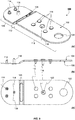
Figure 5 shows an illustration of an example embodiment of the connector of the present invention (a) perspective view, (b) side-view and (c) top-view; -
Figure 6 shows (a) a perspective view and (b) a side-view of the connector and an end portion of the perforated brace band during assembly; -
Figure 7 shows (a) a perspective view and (b) a side-view of the connector and an end portion of the perforated brace band once assembled (i.e. pressed together) and ready for tensioning; -
Figure 8 shows (a) and (b) a perspective view of an assembled wind brace band system where the tensioner is provided at the interface between the connector and the end bracket utilising a single perforated brace band, and (c) a partial perspective view of an assembled wind brace band system where the tensioner is provided centrally between two perforated brace bands; -
Figure 9 shows an illustration of another example embodiment of the connector of the present invention in (a) perspective view and (a) top-view, including an alternative profile design of the connector. - The described example embodiment relates to a connector for a brace band system, and in particular for a wind brace band system particularly suitable for timber structures, such as roof trusses. However, the invention is not necessarily restricted to bracing systems for timber structures but may also be used with any other perforated band system that requires some kind of connection with the perforated band.
- Certain terminology is used in the following description for convenience only and is not limiting. The words 'right', 'left', 'lower', 'upper', 'front', 'rear', 'upward', 'down' and 'downward' designate directions in the drawings to which reference is made and are with respect to the described component when assembled and mounted. The words 'inner', 'inwardly' and 'outer', 'outwardly' refer to directions toward and away from, respectively, a designated centreline or a geometric centre of an element being described (e.g. central axis), the particular meaning being readily apparent from the context of the description.
- Further, as used herein, the terms 'connected', 'attached', 'coupled', 'mounted' are intended to include direct connections between two members without any other members interposed therebetween, as well as, indirect connections between members in which one or more other members are interposed therebetween. The terminology includes the words specifically mentioned above, derivatives thereof, and words of similar import.
- Further, unless otherwise specified, the use of ordinal adjectives, such as, 'first', 'second', 'third' etc. merely indicate that different instances of like objects are being referred to and are not intended to imply that the objects so described must be in a given sequence, either temporally, spatially, in ranking or in any other manner. Like reference numerals are used to depict like features throughout. Also, the terms 'rivet' and 'pin' are used interchangeably and are intended to include permanently attached pins or rivets (e.g. glued, soldered or welded etc.), but also pins and rivets removably coupled, such as, rivets that are attached and fixingly retained through a suitable aperture (friction-lock rivet or movable pins).
- Referring now to
Figure 5 , an example embodiment of aconnector 100 suitable for perforated brace bands of a bracing system is shown. Theconnector 100 comprises aplate structure 102 having a substantially planarupper surface 104 and a substantially planarlower surface 106. Moreover, theplate structure 102 includes afirst end portion 108 and asecond end portion 110, as well as, astep portion 112 joining the first 108 and second 110 end portion. - In this particular example, the
first end portion 108 is provided with two substantiallyrigid pins 114 and one substantially resilient rivet or pin 116, each one projecting away from theupper surface 104. The substantiallyrigid pins 114 and substantially resilient rivet or pin 116 are arranged, so as to matingly match respective holes of the to be coupled perforated brace band 200 (see, for example,Figure 6 ). Thesecond end portion 110 is provided with fourrigid pins 114 and one resilient rivet or pin 116, each one projecting away from thelower surface 106, i.e. into a direction opposite to the pins orrivets upper surface 104. Thestep portion 112 comprises anaperture 124 suitable to guidingly receive theperforated brace band 200. Furthermore, thestep portion 112 parallelly offsets the first 108 and second 110 end portions in a direction normal to any one of the upper 104 or lower 106 surface by a distance that is suitable to accommodate for the operably engagingperforated brace band 200, i.e. relative to the thickness of theperforated brace band 200. In particular and preferably, the distance between thelower surface 106 and the offsetupper surface 104 is such that theperforated brace band 200 is able to operably engage with therigid pins 114 andresilient pin 116 of thefirst end portion 108 and therigid pins 114 andresilient pin 116 of thesecond end portion 110, while aligning substantially parallel with the upper 104 and lower 106 surface of the plate structure 102 (see, for example,Figure 7(b) ). - In a preferred embodiment, the
plate structure 102 and the substantiallyrigid pins 114 may be made from a metal or metal alloy, wherein the substantially resilient pin or rivet may be made from a polymer, such as, for example, a resiliently malleable plastic material suitable to provide a temporarily retaining interference fit with a respective hole of theperforated brace band 200. The metal pins 114 may be permanently attached to the plate structure 102 (e.g. glued, soldered, welded, or even as integral part of theplate structure 102 by pressing the pin out of the plate structure 102). Alternatively, the metal pins 114 may be removably but fixingly pushed through respective holes (not shown) in the plate structure 102 (the pin shaft may provide an interference fit with the hole and the pin head functions as a stop). The resilient plastic rivets orpins 116 may be removably but retainingly pushed through arespective hole 120 in theplate structure 102. The plastic rivet or pin 116 may comprise a head portion (flat head) adapted to stop the plastic rivet or pin 116 from pushing out of thehole 120. The removable plastic rivet or pin 116 allows for replacement in the event the "softer" rivet or pin 116 is damaged or wears out from repeated use. Alternatively, the plastic rivet or pin 116 may be permanently attached to theplate structure 102. In yet another alternative embodiment, theconnector 100 may be used without the resilient plastic rivets or pins 116, i.e. when not needed during installation. - However, it is understood by the person skilled in the art, that any suitable material may be used for the
plate structure 102, the rigid pins orrivets 114, as well as, the "softer" resiliently malleable pin orrivet 116. - Further, in order to accommodate for the two
metal pins 114 and one plastic rivet or pin 116 at thefirst end portion 108, and the fourmetal pins 114 and one plastic rivet or pin 116, as well as, amount aperture 122 at thesecond end portion 110, thefirst end portion 108 may be shorter in length than thesecond end portion 110 for this particular example embodiment. However, depending on the requirement of the system used with theconnector 100 of the present invention, thefirst end portion 108 and thesecond end portion 110 may be of any suitable length and may comprise any number and pattern ofmetal pins 114 and plastic rivets orpins 116 appropriate for a particular bracing system and/or a particular perforated brace band. - Referring now to
Figures 6, 7 and8 , the use of theconnector 100 is described in combination with the assembly of a windbrace band system 300. - A wind
brace band system 300, or any other brace band system, typically includes aperforated brace band 200 having suitably patternedholes 202 fitting onto and matching the pattern of the pins and/orrivets connector 100. During assembly, an end portion of theperforated brace band 200 is pushed through theaperture 124 of thestep portion 112 at an angle relative to the upper 104 and/or lower 106 surface of the plate structure (i.e. so as not to interfere with the pins orrivets 114, 116). When theholes 202 of theperforated brace band 200 are aligned with respective pins orrivets perforated brace band 200 is rotated (by hand) about thestep portion 112 so as to force therigid pins 114 and resilient pins orrivets 116 intorespective holes 202. The friction fit with the resilient pin(s) or rivet(s) 116 provided at the first 108 and/or second 110 end portion maintains the engagement of theperforated brace band 200 with theconnector 100, i.e. the parallelly aligned position of theperforated brace band 200 with respect to the upper 104 and lower 106 surface of theplate structure 102 is fixed into place until the windbrace band system 300 is tightened. - Once the
perforated brace band 200 is mounted torespective connectors 100 of the windbrace band system 300, atensioner 400, provided at one end of the windbrace band system 300 is operated, so as to tighten the coupling between theconnectors 100 andperforated brace band 200.Figure 8 illustrates the tightening of the windbrace band system 300 by rotating the tensioner 400 (direction of arrow) and reducing the distance between theend brackets - A portion of an alternative wind
brace band system 500 is shown inFigure 8 (c) , comprising, inter alia, twoperforated brace bands 200, coupled to acentral tensioner 400 viarespective connectors 100. Also, theconnector 100 of the present invention, may be coupled to thetensioner 400 and/or endbrackets mount 122. In this particular example, themount 122 is an aperture configured to receive abolt 304 so as to movably couple theconnector 100 to theend bracket tensioner 400. Thecoupling connector 100 and respective one of theend bracket tensioner 400 . -
Figure 9 shows an alternative design of theplate structure 102 of theconnector 100 of the present invention, i.e. having a narrowed mid-section. However, it is understood that theplate structure 102 may have any suitable shape, any number and pattern of pins orrivets suitable mount 122 for coupling theconnector 100 to an external component. - It will be appreciated by persons skilled in the art that the above embodiment(s) have been described by way of example only and not in any limitative sense, and that various alterations and modifications are possible without departing from the scope of the invention as defined by the appended claims. Various modifications to the detailed designs as described above are possible.
Claims (14)
- A connector for anchoring perforated brace bands, comprising:
a plate member, having an upper surface and a lower surface opposing said upper surface, said pate member further comprising:a first end portion, comprising at least one first-type rivet, operably coupled to and projecting away from said upper surface and configured to couplingly engage with perforations of a first portion of a perforated brace band;a second end portion, opposite said first end portion, comprising at least one of said first-type rivet operably coupled to and projecting away from said lower surface and configured to couplingly engage with perforations of a second portion of the perforated brace band, anda step portion, provided between said first end portion and said second end portion, having at least one aperture configured to guidingly receive the perforated brace band,
wherein said second end portion is parallelly offset from said first end portion by a predetermined distance in a direction normal to said upper surface via said step portion. - A connector according to any one of the preceding claims, wherein said predetermined distance is defined so as to substantially parallelly align the perforated brace band with said upper and lower surface of said plate when couplingly engaged with said at least one first-type rivet of said first end portion and said at least one first-type rivet of said second end portion, during use.
- A connector according to any one of the preceding claims, wherein said first end portion comprises a plurality of said first-type rivets arranged so as to couplingly engage with perforations of the first portion of the perforated brace band, during use.
- A connector according to claim 3, wherein said first end portion comprises at least two first-type rivets.
- A connector according to any one of the preceding claims, wherein said second end portion comprises a plurality of said first-type rivets operably arranged on said lower surface so as to couplingly engage with perforations of the second portion of the perforated brace band, during use.
- A connector according to claim 5, wherein said second end portion comprises at least four first-type rivets.
- A connector according to any one of the preceding claims, wherein said first end portion and/or said second end portion further comprise at least one second-type rivet operably coupled to and projecting away from respective one of said upper surface and said lower surface of said plate member, and configured to couplingly and retainingly engage with perforations of respective first and second portion of the perforated brace band.
- A connector according to claim 7, wherein said at least one second-type rivet is made from a resilient material adapted to provide a retaining interference fit with respective perforations of the perforated brace band.
- A connector according to claim 8, wherein said resilient material is a polymer.
- A connector according to any one of the preceding claims, wherein said plate member is made from metal.
- A connector according to any one of the preceding claims, wherein said at least one first-type rivet is made from metal.
- A connector according to any one of the preceding claims, wherein said second end portion further comprises a mount adapted to operably couple said plate member to an external structure.
- A connector according to claim 12, wherein said mount is an aperture configured to couplingly receive a connection bolt.
- A wind brace band system comprising a first and second brace mount, at least one tensioner, at least one perforated brace band and at least one connector according to any one of claims 1 to 13.
Priority Applications (5)
| Application Number | Priority Date | Filing Date | Title |
|---|---|---|---|
| EP19204391.7A EP3812526A1 (en) | 2019-10-21 | 2019-10-21 | A perforated brace band connector and a brace band system |
| DK20199927.3T DK3812527T3 (en) | 2019-10-21 | 2020-10-02 | A PERFORATED BAND CONNECTOR ELEMENT AND A BAND SYSTEM |
| EP20199927.3A EP3812527B1 (en) | 2019-10-21 | 2020-10-02 | A perforated brace band connector and a brace band system |
| PCT/US2020/055235 WO2021080805A1 (en) | 2019-10-21 | 2020-10-12 | A perforated brace band connector and a brace band system |
| AU2020372304A AU2020372304A1 (en) | 2019-10-21 | 2020-10-12 | A perforated brace band connector and a brace band system |
Applications Claiming Priority (1)
| Application Number | Priority Date | Filing Date | Title |
|---|---|---|---|
| EP19204391.7A EP3812526A1 (en) | 2019-10-21 | 2019-10-21 | A perforated brace band connector and a brace band system |
Publications (1)
| Publication Number | Publication Date |
|---|---|
| EP3812526A1 true EP3812526A1 (en) | 2021-04-28 |
Family
ID=68296291
Family Applications (2)
| Application Number | Title | Priority Date | Filing Date |
|---|---|---|---|
| EP19204391.7A Withdrawn EP3812526A1 (en) | 2019-10-21 | 2019-10-21 | A perforated brace band connector and a brace band system |
| EP20199927.3A Active EP3812527B1 (en) | 2019-10-21 | 2020-10-02 | A perforated brace band connector and a brace band system |
Family Applications After (1)
| Application Number | Title | Priority Date | Filing Date |
|---|---|---|---|
| EP20199927.3A Active EP3812527B1 (en) | 2019-10-21 | 2020-10-02 | A perforated brace band connector and a brace band system |
Country Status (4)
| Country | Link |
|---|---|
| EP (2) | EP3812526A1 (en) |
| AU (1) | AU2020372304A1 (en) |
| DK (1) | DK3812527T3 (en) |
| WO (1) | WO2021080805A1 (en) |
Cited By (2)
| Publication number | Priority date | Publication date | Assignee | Title |
|---|---|---|---|---|
| US20230128163A1 (en) * | 2020-03-04 | 2023-04-27 | Simpson Strong-Tie A/S | Wind Brace Tensioning Bracket and Tensioning System |
| EP4459060A1 (en) * | 2023-05-02 | 2024-11-06 | Illinois Tool Works Inc. | A plate member and retaining for anchoring perforated brace bands and method of manufacture |
Citations (4)
| Publication number | Priority date | Publication date | Assignee | Title |
|---|---|---|---|---|
| US4160350A (en) * | 1978-07-03 | 1979-07-10 | Craib Rupert G | Floor joist plate |
| DE9200786U1 (en) * | 1992-01-21 | 1992-03-12 | BMF-Baubeschläge Bentsen GmbH & Co KG, 2390 Flensburg | Device for connecting an element of a building to a holding device |
| EP2281965A2 (en) * | 2009-07-01 | 2011-02-09 | ITW Construction Products ApS | A coupling device for a wind bracing system and a wind bracing system |
| US20190285224A1 (en) * | 2018-03-16 | 2019-09-19 | Studco Australia Pty Ltd | Bracket assembly for bracing two structures |
Family Cites Families (1)
| Publication number | Priority date | Publication date | Assignee | Title |
|---|---|---|---|---|
| GB2495742A (en) * | 2011-10-19 | 2013-04-24 | Simpson Strong Tie Co Inc | Securing device for a tensioning system for reinforcing trusses in a roof |
-
2019
- 2019-10-21 EP EP19204391.7A patent/EP3812526A1/en not_active Withdrawn
-
2020
- 2020-10-02 DK DK20199927.3T patent/DK3812527T3/en active
- 2020-10-02 EP EP20199927.3A patent/EP3812527B1/en active Active
- 2020-10-12 AU AU2020372304A patent/AU2020372304A1/en not_active Abandoned
- 2020-10-12 WO PCT/US2020/055235 patent/WO2021080805A1/en not_active Ceased
Patent Citations (4)
| Publication number | Priority date | Publication date | Assignee | Title |
|---|---|---|---|---|
| US4160350A (en) * | 1978-07-03 | 1979-07-10 | Craib Rupert G | Floor joist plate |
| DE9200786U1 (en) * | 1992-01-21 | 1992-03-12 | BMF-Baubeschläge Bentsen GmbH & Co KG, 2390 Flensburg | Device for connecting an element of a building to a holding device |
| EP2281965A2 (en) * | 2009-07-01 | 2011-02-09 | ITW Construction Products ApS | A coupling device for a wind bracing system and a wind bracing system |
| US20190285224A1 (en) * | 2018-03-16 | 2019-09-19 | Studco Australia Pty Ltd | Bracket assembly for bracing two structures |
Cited By (2)
| Publication number | Priority date | Publication date | Assignee | Title |
|---|---|---|---|---|
| US20230128163A1 (en) * | 2020-03-04 | 2023-04-27 | Simpson Strong-Tie A/S | Wind Brace Tensioning Bracket and Tensioning System |
| EP4459060A1 (en) * | 2023-05-02 | 2024-11-06 | Illinois Tool Works Inc. | A plate member and retaining for anchoring perforated brace bands and method of manufacture |
Also Published As
| Publication number | Publication date |
|---|---|
| WO2021080805A1 (en) | 2021-04-29 |
| DK3812527T3 (en) | 2023-04-24 |
| EP3812527B1 (en) | 2023-02-15 |
| EP3812527A1 (en) | 2021-04-28 |
| AU2020372304A1 (en) | 2022-05-12 |
Similar Documents
| Publication | Publication Date | Title |
|---|---|---|
| US20040055233A1 (en) | Anchor attachment for a roof panel rib | |
| US5553685A (en) | Roof safety anchor | |
| US6408587B2 (en) | Structural members and associated parts | |
| EP3812527B1 (en) | A perforated brace band connector and a brace band system | |
| US8424958B2 (en) | Butt joint for trailer side wall | |
| US3679250A (en) | Splicer for reinforcing bars | |
| CA2264127C (en) | Connector plate and method of assembly | |
| US7878547B2 (en) | Seatbelt anchor assembly | |
| CN108291396B (en) | Support device and assembly thereof | |
| US8579569B2 (en) | Retaining cam for a rotary fastener | |
| US5301986A (en) | Clamp | |
| EP2093343B1 (en) | Tension device for connection and tensioning of means connected to construction elements and method for producing the tension device | |
| CN109383982A (en) | Bar for farming machine is with the bar band of conveyer | |
| MX2007000530A (en) | Hose clamp. | |
| US6478112B2 (en) | Rail mounted fall arrest assembly | |
| JP4067649B2 (en) | Parent rope support structure | |
| EP0551202B1 (en) | Structural connection | |
| KR102694452B1 (en) | Profile connection structure | |
| JP2860522B2 (en) | Metal fixing bracket for steel base material | |
| US7452153B2 (en) | Fitting for joining scaffold boards | |
| EP4459060A1 (en) | A plate member and retaining for anchoring perforated brace bands and method of manufacture | |
| JPS62174458A (en) | Handrail for work | |
| AU2013209390B2 (en) | A Structural Connector | |
| KR102717801B1 (en) | One-way bolt fastening device | |
| US20250002297A1 (en) | System and method for the construction of a multi-planar lightweight integrated post and handrail assembly |
Legal Events
| Date | Code | Title | Description |
|---|---|---|---|
| PUAI | Public reference made under article 153(3) epc to a published international application that has entered the european phase |
Free format text: ORIGINAL CODE: 0009012 |
|
| STAA | Information on the status of an ep patent application or granted ep patent |
Free format text: STATUS: THE APPLICATION HAS BEEN PUBLISHED |
|
| AK | Designated contracting states |
Kind code of ref document: A1 Designated state(s): AL AT BE BG CH CY CZ DE DK EE ES FI FR GB GR HR HU IE IS IT LI LT LU LV MC MK MT NL NO PL PT RO RS SE SI SK SM TR |
|
| AX | Request for extension of the european patent |
Extension state: BA ME |
|
| STAA | Information on the status of an ep patent application or granted ep patent |
Free format text: STATUS: THE APPLICATION IS DEEMED TO BE WITHDRAWN |
|
| 18D | Application deemed to be withdrawn |
Effective date: 20211029 |