EP3812286A1 - Anti-collision light assembly - Google Patents
Anti-collision light assembly Download PDFInfo
- Publication number
- EP3812286A1 EP3812286A1 EP20190648.4A EP20190648A EP3812286A1 EP 3812286 A1 EP3812286 A1 EP 3812286A1 EP 20190648 A EP20190648 A EP 20190648A EP 3812286 A1 EP3812286 A1 EP 3812286A1
- Authority
- EP
- European Patent Office
- Prior art keywords
- annular reflector
- retainer
- base
- radially outward
- light assembly
- Prior art date
- Legal status (The legal status is an assumption and is not a legal conclusion. Google has not performed a legal analysis and makes no representation as to the accuracy of the status listed.)
- Granted
Links
Images


Classifications
-
- B—PERFORMING OPERATIONS; TRANSPORTING
- B64—AIRCRAFT; AVIATION; COSMONAUTICS
- B64D—EQUIPMENT FOR FITTING IN OR TO AIRCRAFT; FLIGHT SUITS; PARACHUTES; ARRANGEMENT OR MOUNTING OF POWER PLANTS OR PROPULSION TRANSMISSIONS IN AIRCRAFT
- B64D47/00—Equipment not otherwise provided for
- B64D47/02—Arrangements or adaptations of signal or lighting devices
- B64D47/06—Arrangements or adaptations of signal or lighting devices for indicating aircraft presence
-
- F—MECHANICAL ENGINEERING; LIGHTING; HEATING; WEAPONS; BLASTING
- F21—LIGHTING
- F21S—NON-PORTABLE LIGHTING DEVICES; SYSTEMS THEREOF; VEHICLE LIGHTING DEVICES SPECIALLY ADAPTED FOR VEHICLE EXTERIORS
- F21S43/00—Signalling devices specially adapted for vehicle exteriors, e.g. brake lamps, direction indicator lights or reversing lights
- F21S43/10—Signalling devices specially adapted for vehicle exteriors, e.g. brake lamps, direction indicator lights or reversing lights characterised by the light source
- F21S43/13—Signalling devices specially adapted for vehicle exteriors, e.g. brake lamps, direction indicator lights or reversing lights characterised by the light source characterised by the type of light source
- F21S43/14—Light emitting diodes [LED]
-
- F—MECHANICAL ENGINEERING; LIGHTING; HEATING; WEAPONS; BLASTING
- F21—LIGHTING
- F21S—NON-PORTABLE LIGHTING DEVICES; SYSTEMS THEREOF; VEHICLE LIGHTING DEVICES SPECIALLY ADAPTED FOR VEHICLE EXTERIORS
- F21S43/00—Signalling devices specially adapted for vehicle exteriors, e.g. brake lamps, direction indicator lights or reversing lights
- F21S43/30—Signalling devices specially adapted for vehicle exteriors, e.g. brake lamps, direction indicator lights or reversing lights characterised by reflectors
- F21S43/31—Optical layout thereof
-
- F—MECHANICAL ENGINEERING; LIGHTING; HEATING; WEAPONS; BLASTING
- F21—LIGHTING
- F21S—NON-PORTABLE LIGHTING DEVICES; SYSTEMS THEREOF; VEHICLE LIGHTING DEVICES SPECIALLY ADAPTED FOR VEHICLE EXTERIORS
- F21S43/00—Signalling devices specially adapted for vehicle exteriors, e.g. brake lamps, direction indicator lights or reversing lights
- F21S43/601—Signalling devices specially adapted for vehicle exteriors, e.g. brake lamps, direction indicator lights or reversing lights characterised by variable optical properties, e.g. involving the use of LCD or movable parts
-
- B—PERFORMING OPERATIONS; TRANSPORTING
- B64—AIRCRAFT; AVIATION; COSMONAUTICS
- B64D—EQUIPMENT FOR FITTING IN OR TO AIRCRAFT; FLIGHT SUITS; PARACHUTES; ARRANGEMENT OR MOUNTING OF POWER PLANTS OR PROPULSION TRANSMISSIONS IN AIRCRAFT
- B64D2203/00—Aircraft or airfield lights using LEDs
-
- B—PERFORMING OPERATIONS; TRANSPORTING
- B64—AIRCRAFT; AVIATION; COSMONAUTICS
- B64D—EQUIPMENT FOR FITTING IN OR TO AIRCRAFT; FLIGHT SUITS; PARACHUTES; ARRANGEMENT OR MOUNTING OF POWER PLANTS OR PROPULSION TRANSMISSIONS IN AIRCRAFT
- B64D45/00—Aircraft indicators or protectors not otherwise provided for
-
- F—MECHANICAL ENGINEERING; LIGHTING; HEATING; WEAPONS; BLASTING
- F21—LIGHTING
- F21S—NON-PORTABLE LIGHTING DEVICES; SYSTEMS THEREOF; VEHICLE LIGHTING DEVICES SPECIALLY ADAPTED FOR VEHICLE EXTERIORS
- F21S43/00—Signalling devices specially adapted for vehicle exteriors, e.g. brake lamps, direction indicator lights or reversing lights
- F21S43/10—Signalling devices specially adapted for vehicle exteriors, e.g. brake lamps, direction indicator lights or reversing lights characterised by the light source
- F21S43/19—Attachment of light sources or lamp holders
- F21S43/195—Details of lamp holders, terminals or connectors
-
- F—MECHANICAL ENGINEERING; LIGHTING; HEATING; WEAPONS; BLASTING
- F21—LIGHTING
- F21W—INDEXING SCHEME ASSOCIATED WITH SUBCLASSES F21K, F21L, F21S and F21V, RELATING TO USES OR APPLICATIONS OF LIGHTING DEVICES OR SYSTEMS
- F21W2103/00—Exterior vehicle lighting devices for signalling purposes
- F21W2103/10—Position lights
-
- F—MECHANICAL ENGINEERING; LIGHTING; HEATING; WEAPONS; BLASTING
- F21—LIGHTING
- F21W—INDEXING SCHEME ASSOCIATED WITH SUBCLASSES F21K, F21L, F21S and F21V, RELATING TO USES OR APPLICATIONS OF LIGHTING DEVICES OR SYSTEMS
- F21W2107/00—Use or application of lighting devices on or in particular types of vehicles
- F21W2107/30—Use or application of lighting devices on or in particular types of vehicles for aircraft
-
- F—MECHANICAL ENGINEERING; LIGHTING; HEATING; WEAPONS; BLASTING
- F21—LIGHTING
- F21Y—INDEXING SCHEME ASSOCIATED WITH SUBCLASSES F21K, F21L, F21S and F21V, RELATING TO THE FORM OR THE KIND OF THE LIGHT SOURCES OR OF THE COLOUR OF THE LIGHT EMITTED
- F21Y2105/00—Planar light sources
- F21Y2105/10—Planar light sources comprising a two-dimensional [2D] array of point-like light-generating elements
- F21Y2105/14—Planar light sources comprising a two-dimensional [2D] array of point-like light-generating elements characterised by the overall shape of the two-dimensional [2D] array
- F21Y2105/18—Planar light sources comprising a two-dimensional [2D] array of point-like light-generating elements characterised by the overall shape of the two-dimensional [2D] array annular; polygonal other than square or rectangular, e.g. for spotlights or for generating an axially symmetrical light beam
-
- F—MECHANICAL ENGINEERING; LIGHTING; HEATING; WEAPONS; BLASTING
- F21—LIGHTING
- F21Y—INDEXING SCHEME ASSOCIATED WITH SUBCLASSES F21K, F21L, F21S and F21V, RELATING TO THE FORM OR THE KIND OF THE LIGHT SOURCES OR OF THE COLOUR OF THE LIGHT EMITTED
- F21Y2115/00—Light-generating elements of semiconductor light sources
- F21Y2115/10—Light-emitting diodes [LED]
Definitions
- the present disclosure relates to light assemblies, and more specifically anti-collision light assemblies for vehicles.
- Vehicles often use high-intensity anti-collision lights to alert nearby observers of the vehicle's presence in order to reduce the likelihood of a collision.
- specific regulations define light intensity requirements.
- FAA Federal Aviation Administration
- aircraft anti-collision lights benefit from directing light 360° about a horizontal plane.
- Such anti-collision lights improve the visibility of aircraft, thereby allowing air traffic controllers and other aircraft to visually identify and orient the aircraft.
- Conventional anti-collision light assemblies generally include one or more reflectors that redirect light to meet the visibility standards of regulating entities such as the FAA.
- the reflective surface(s) of conventional light assemblies may have distortions or may be improperly aligned relative to light sources, and thus the pattern of emitted light may be adversely affected.
- the present disclosure provides a light assembly that includes a base, an annular reflector, and a retainer.
- the base includes one or more light sources mounted thereto.
- the annular reflector comprises a first radially outward surface and a first radially inward surface.
- the annular reflector also defines a central longitudinal axis, with the first radially outward surface including a reflective surface.
- the retainer is coupled to the base and comprises a second radially outward surface. The second radially outward surface of the retainer seats against the first radially inward surface of the annular reflector to retain the annular reflector in a desired position relative to the light source mounted to the base.
- the annular reflector comprises a first end rim disposed toward the base and a second end rim extending away from the base.
- the first end rim may have a first radius and the second end rim may have a second radius, with the second radius being larger than the first radius.
- the reflective surface of the annular reflector may be concave from the first end rim to the second end rim.
- the reflective surface of the annular reflector is parabolic from the first end rim to the second end rim.
- the axis of symmetry of the parabolic reflective surface may be perpendicular to the central longitudinal axis of the annular reflector.
- a seated interface of the light assembly is defined as a region of direct contact between the second radially outward surface of the retainer and the first radially inward surface of the annular reflector.
- the reflective surface of the annular reflector and the seated interface have a same profile, according to various embodiments.
- a wall thickness of the annular reflector between the seated interface and the reflective surface is constant.
- the light source is a first light source of a plurality of light sources.
- the plurality of lights sources may be circumferentially distributed around the annular reflector (e.g., the plurality of light sources may be concentric with the annular reflector).
- an anti-collision light assembly of an aircraft is also disclosed herein, according to various embodiments.
- the anti-collision light assembly may comprise the features discussed above.
- the method may include positioning an annular reflector adjacent a base, wherein the base comprises a plurality of light sources.
- the method may also include inserting a retainer into a central bore defined by the annular reflector.
- the method may include coupling the retainer to the base such that a radially outward surface of the retainer engages a radially inward surface of the annular reflector to retain the annular reflector in a desired position relative to the plurality of light sources.
- a seated interface of the light assembly in response to coupling the retainer to the base, is defined as a region of direct contact between the radially outward surface of the retainer and the radially inward surface of the annular reflector.
- a wall thickness of the annular reflector along the seated interface is constant.
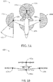
- FIG. 1A illustrates a top view of an aircraft 101 including multiple anti-collision lights 100, in accordance with various embodiments.
- FIG. 1B illustrates a front profile view of an aircraft 101 including multiple anti-collision lights 100, in accordance with various embodiments.
- aircraft 101 may include a first anti-collision light 100a disposed on the tail of the aircraft 101, a second anti-collision light 100b disposed on a lower surface of a fuselage of the aircraft 101, and third and fourth anti-collision lights 100c, 100d disposed on the wings of the aircraft 101. It is noted herein that additional and/or alternative anti-collision lights 100 may be used without departing from the spirit or scope of the present disclosure.
- aircraft 101 may include an anti-collision light 100 disposed on an upper surface of the fuselage of the aircraft 101.
- the one or more anti-collision lights 100 are configured to emit light across an illumination field of view 103 (e.g., an emitted light pattern).
- An illumination field of view 103 e.g., 103a, 103b, 103c, 103d
- An illumination field of view 103 may be defined as a plurality of horizontal and vertical angles through which an anti-collision light 100 emits illumination.
- an illumination field of view 103 may be defined by a lateral angle ( ⁇ ) 105.
- anti-collision light 100c may be configured to emit light across an illumination field of view 103c.
- anti-collision light 100a may be configured to emit light across an illumination field of view 103a, wherein the illumination field of view 103a is defined by a 360° lateral angle 105.
- lights configured to provide illumination for a single hemisphere (e.g., upper hemisphere, lower hemisphere).
- the anti-collision lights 100 of the present disclosure may be utilized by any aircraft known in the art including, but not limited to, jet aircraft, commercial aircraft, military aircraft, and the like. While numerous details are included herein pertaining to implementing and using the anti-collision light assembly with aircraft, the scope of this disclosure is not necessarily limited to aircraft.
- the light assemblies disclosed herein may be implemented on other airborne vehicles (e.g., helicopters), land-based vehicles (e.g., automobiles, motorcycles, military vehicles), aquatic vehicles (e.g., passenger boats, commercial ships, etc.), and the like. Further, the light assemblies disclosed herein may be used as beacons or other light emitters for structures and buildings.
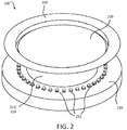
- a light assembly 200 is provided.
- the light assembly 200 may be utilized as one or more of the anti-collision lights 100 described above. That is, base 210 of the light assembly 200 may be mounted or otherwise affixed to a portion of the aircraft 101.
- the light assembly 200 generally includes base 210, an annular reflector 220, and a retainer 230, according to various embodiments.
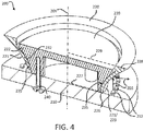
- the base 210 as described in greater detail below, generally includes one or more light sources 212 mounted thereto, according to various embodiments. Emitted light 203 ( FIG. 4 ) from the plurality of light sources 212 is reflected off a reflective surface 213 ( FIG.
- the annular reflector 220 is held in position via the retainer 230, which is coupled to the base 210. That is, the annular reflector 220 may be compressed between the base 210 and the retainer 230 to hold the annular reflector 220 in place.
- the light assembly 200 has various benefits over conventional lights, according to various embodiments.
- light assembly 200 may provide a 360° or substantially 360° light pattern using a single set of light sources 212 that are mounted to the single base 210 and circumferentially distributed around the single annular reflector 220.
- the light assembly 200 may be implemented with reduced materials, less cost, and/or less weight than conventional assemblies, which may also result in various performance and durability advantages.
- annular reflector 220 and the retainer 230 are separate components, various manufacturing and design benefits may be realized. For example, instead of sacrificing quality and/or reflectivity of a reflector in order to provide sufficient structural mounting integrity, the optical performance of the annular reflector 220 can be tuned independently of the need for structural suitableness because the separate retainer 230 component provides the requisite mounting structure, according to various embodiments.
- a conventional reflector may include reinforcing ribs or other structural features through which fasteners may be inserted to mount the reflector, and these structural features may adversely affect the optical performance of the conventional reflector (e.g., may introduce optical distortions).
- fasteners 240 may be utilized to couple the retainer 230 directly to the base 210, with the annular reflector 220 being wedged therebetween. Additional details pertaining to the features of the light assembly 200 and the associated benefits/advantages are provided below.
- the annular reflector 220 defines a central bore 225, and a central longitudinal axis 205 extends centrally through the central bore 225.
- the annular reflector 220 may have a first radially outward surface 221 and a first radially inward surface 222.
- the terms "radially outward” and “radially inward” refer generally to positions of surfaces/components along a radial direction relative to the central longitudinal axis 205. That is, the first radially outward surface 221 of the annular reflector 220 generally faces away from the central longitudinal axis 205 and the first radially inward surface 222 generally faces toward the central longitudinal axis 205.
- the first radially outward surface 221 of the annular reflector 220 comprises a reflective surface 223.
- the retainer 230 comprises a second radially outward surface 232 that seats against the first radially inward surface 222 of the annular reflector 220 in an assembled/installed configuration. This engagement between the second radially outward surface 232 of the retainer 230 and the first radially inward surface 222 of the annular reflector holds and retains the annular reflector 220 in a desired position relative to the light sources 212 mounted to the base 210, according to various embodiments. Said differently, a seated interface 235 ( FIG.
- the second radially outward surface 232 of the retainer 230 and the first radially inward surface 222 of the annular reflector 220 have the same or substantially the same profile, and are thus configured to be in contouring/complementing engagement with each other.
- the complementary geometries of these surfaces 232, 222 may allow the retainer 230 to provide a uniform retention force to the annular reflector 220, thereby uniformly compressing the annular reflector 220 between the seated interface 235 and the base 210 to securely hold the annular reflector 220 in position relative to the base 210.
- This uniform retention force transmitted from the retainer 230 to the annular reflector 220 along the seated interface 235 promotes and facilitates the accurate and precise emanation of light 203 from the light sources 212 and off of the reflective surface 223 of the annular reflector 220, according to various embodiments.
- the first radially outward surface 221 (e.g., the reflective surface 223) also has the same profile as the seated interface 235.
- a wall thickness of the annular reflector 220 between the seated interface 235 and the reflective surface 223 may be constant.
- the constant wall thickness of this region of the annular reflector 220 may improve the ability of the reflective surface 223 of the annular reflector 220 to accurately and precisely reflect the light 203.
- optical distortions may be minimized or substantially minimized because of the uniform/constant wall thickness of the annular reflector 220 between the seated interface 235 and the reflective surface 223 portion of the annular reflector 220.
- the annular reflector 220 is exclusively retained to the base 210 via the seated interface 235. That is, the light assembly 200 may not include fasteners or other mounting features that extend directly between the base 210 and the annular reflector 220, but instead the retainer 230 may receive the fasteners 240 which extend to/through the base 210 for holding the assembly together.
- the annular reflector comprises a first end rim 226 that is disposed toward (i.e., faces) the base 210 and a second end rim 228 that extends away from the base 210.
- the annular reflector 220 and thus the retainer 230 may have the conical, tapering shape shown in the figures. That is, the first end rim 226 may have a first radius 227 and the second end rim 228 may have a second radius 229, with the second radius 229 being larger than the first radius 227.
- the reflective surface 223 of the annular reflector 220 extending from the first end rim 226 to the second end rim 228 is concave.
- the reflective surface 223 is parabolic. Said differently, an axis of symmetry of the parabolic reflective surface 223 is perpendicular to the central longitudinal axis 205. This axis of symmetry may extend along the surface of the base 210 (or may at least be substantially parallel to the surface of the base 210).
- the reflective surface 223 may be a paraboloid with the plurality of light sources 212 being disposed generally at the focus of the paraboloid.
- the curved profile of the reflective surface 223 may be defined by a hyperbolic, parabolic, or complex polynomial equation, among others.
- the light sources 212 are mounted or otherwise coupled to the base 210.
- the base 210 may be a substrate that includes electronic circuitry (e.g., a printed circuit board), and the light sources 212 may be operably coupled to this electronic circuitry.
- the light sources are light emitting diodes ("LEDs").
- the one or more light sources 212 are disposed/coupled to the base 210 in specified orientations configured to facilitate a desired illumination field of view.
- the plurality of light sources 212 may be disposed on the base 210 in a closed curve configuration. That is, the plurality of light sources 212 may be positioned adjacent each other to have a specific shape across the surface of the base 210.
- the shape may be a circle, an oval, an ellipse, a polygon (e.g., triangle, square, rectangle), and the like.
- the light sources 212 are symmetrically distributed about the central longitudinal axis 205. That is, the light sources 212 may be arranged around the first end rim 226 of the annular reflector 220. In various embodiments, the arrangement of light sensors is concentric with the annular reflector 220 and the retainer 230. In various embodiments, the second end rim 228 of the annular reflector 220 extends so as to be disposed above the light sources 212.
- the annular reflector 220 is manufactured via an injection molding process.
- the annular reflector 220 may also be made using one or more additive or subtractive manufacturing processes.
- the annular reflector 220 is made from a plastic material with a mirrored surface. Because the annular reflector 220 and the retainer 230 are separate components, the design/configuration of each may be separately optimized (e.g., may be iteratively designed/refined) without necessarily affecting the other. Said differently, the cavities, rigidity, or other features of the retainer 230 may be altered and changed without adversely affecting the optical performance of the annular reflector 220, according to various embodiments.
- a method 590 of assembling a light assembly may include positioning an annular reflector adjacent a base at step 592.
- the method 590 may also include inserting a retainer into a central bore defined by the annular reflector at step 594.
- the method 590 may include coupling the retainer to the base such that a radially outward surface of the retainer engages a radially inward surface of the annular reflector at step 596.
- Step 596 may retain the annular reflector in a desired position relative to the plurality of light sources.
- a seated interface of the light assembly in response to coupling the retainer to the base, is defined as a region of direct contact between the radially outward surface of the retainer and the radially inward surface of the annular reflector.
- a wall thickness of the annular reflector along the seated interface is constant.
- any of the method or process descriptions may be executed in any order and are not necessarily limited to the order presented.
- any reference to singular includes plural embodiments, and any reference to more than one component or step may include a singular embodiment or step.
- Elements and steps in the figures are illustrated for simplicity and clarity and have not necessarily been rendered according to any particular sequence. For example, steps that may be performed concurrently or in different order are illustrated in the figures to help to improve understanding of embodiments of the present disclosure.
- Any reference to attached, fixed, connected or the like may include permanent, removable, temporary, partial, full and/or any other possible attachment option. Additionally, any reference to without contact (or similar phrases) may also include reduced contact or minimal contact. Surface shading lines may be used throughout the figures to denote different parts or areas but not necessarily to denote the same or different materials. In some cases, reference coordinates may be specific to each figure.
- references to "one embodiment”, “an embodiment”, “various embodiments”, etc. indicate that the embodiment described may include a particular feature, structure, or characteristic, but every embodiment may not necessarily include the particular feature, structure, or characteristic. Moreover, such phrases are not necessarily referring to the same embodiment. Further, when a particular feature, structure, or characteristic is described in connection with an embodiment, it is submitted that it is within the knowledge of one skilled in the art to affect such feature, structure, or characteristic in connection with other embodiments whether or not explicitly described. After reading the description, it will be apparent to one skilled in the relevant art(s) how to implement the disclosure in alternative embodiments.
Landscapes
- Engineering & Computer Science (AREA)
- General Engineering & Computer Science (AREA)
- Aviation & Aerospace Engineering (AREA)
- Physics & Mathematics (AREA)
- Microelectronics & Electronic Packaging (AREA)
- Optics & Photonics (AREA)
- Non-Portable Lighting Devices Or Systems Thereof (AREA)
- Light Guides In General And Applications Therefor (AREA)
- Liquid Crystal (AREA)
Abstract
Description
- The present disclosure relates to light assemblies, and more specifically anti-collision light assemblies for vehicles.
- Vehicles often use high-intensity anti-collision lights to alert nearby observers of the vehicle's presence in order to reduce the likelihood of a collision. In the context of aviation, specific regulations define light intensity requirements. For example, according to Federal Aviation Administration ("FAA") regulation codified at 14 C.F.R. 25.1401, aircraft anti-collision lights benefit from directing light 360° about a horizontal plane. Such anti-collision lights improve the visibility of aircraft, thereby allowing air traffic controllers and other aircraft to visually identify and orient the aircraft.
- Conventional anti-collision light assemblies generally include one or more reflectors that redirect light to meet the visibility standards of regulating entities such as the FAA. However, due to various manufacturing and installation factors, the reflective surface(s) of conventional light assemblies may have distortions or may be improperly aligned relative to light sources, and thus the pattern of emitted light may be adversely affected.
- In various embodiments, the present disclosure provides a light assembly that includes a base, an annular reflector, and a retainer. The base includes one or more light sources mounted thereto. The annular reflector comprises a first radially outward surface and a first radially inward surface. The annular reflector also defines a central longitudinal axis, with the first radially outward surface including a reflective surface. The retainer is coupled to the base and comprises a second radially outward surface. The second radially outward surface of the retainer seats against the first radially inward surface of the annular reflector to retain the annular reflector in a desired position relative to the light source mounted to the base.
- In various embodiments, the annular reflector comprises a first end rim disposed toward the base and a second end rim extending away from the base. The first end rim may have a first radius and the second end rim may have a second radius, with the second radius being larger than the first radius. The reflective surface of the annular reflector may be concave from the first end rim to the second end rim. In various embodiments, the reflective surface of the annular reflector is parabolic from the first end rim to the second end rim. The axis of symmetry of the parabolic reflective surface may be perpendicular to the central longitudinal axis of the annular reflector.
- In various embodiments, a seated interface of the light assembly is defined as a region of direct contact between the second radially outward surface of the retainer and the first radially inward surface of the annular reflector. The reflective surface of the annular reflector and the seated interface have a same profile, according to various embodiments. In various embodiments, a wall thickness of the annular reflector between the seated interface and the reflective surface is constant. In response to coupling the retainer to the base, the annular reflector is compressed between the second radially outward surface of the retainer and the base. That is, in the installed/assembled configuration, the annular reflector is compressed between the second radially outward surface of the retainer and the base, according to various embodiments. The annular reflector may be exclusively retained to the base via the seated interface between the annular reflector and the retainer.
- In various embodiments, the light source is a first light source of a plurality of light sources. The plurality of lights sources may be circumferentially distributed around the annular reflector (e.g., the plurality of light sources may be concentric with the annular reflector). Also disclosed herein, according to various embodiments, is an anti-collision light assembly of an aircraft. The anti-collision light assembly may comprise the features discussed above.
- Also disclosed herein, according to various embodiments, is a method of assembling a light assembly. The method may include positioning an annular reflector adjacent a base, wherein the base comprises a plurality of light sources. The method may also include inserting a retainer into a central bore defined by the annular reflector. Further, the method may include coupling the retainer to the base such that a radially outward surface of the retainer engages a radially inward surface of the annular reflector to retain the annular reflector in a desired position relative to the plurality of light sources.
- In various embodiments, the radially outward surface of the retainer and the radially inward surface of the annular reflector have a same profile. In such embodiments, in response to coupling the retainer to the base, a seated interface of the light assembly is defined as a region of direct contact between the radially outward surface of the retainer and the radially inward surface of the annular reflector. In various embodiments, a wall thickness of the annular reflector along the seated interface is constant.
- The forgoing features and elements may be combined in various combinations without exclusivity, unless expressly indicated herein otherwise. These features and elements as well as the operation of the disclosed embodiments will become more apparent in light of the following description and accompanying drawings.
-
-
FIG. 1A illustrates a top view of an aircraft having multiple anti-collision lights, in accordance with various embodiments; -
FIG.1B illustrates a front profile view of an aircraft having multiple anti-collision lights, in accordance with various embodiments; -
FIG. 2 illustrates a perspective view of an anti-collision light assembly, in accordance with various embodiments; -
FIG. 3 illustrates an exploded perspective view of an anti-collision light assembly, in accordance with various embodiments; -
FIG. 4 illustrates a cross-sectional view of an anti-collision light assembly, in accordance with various embodiments; and -
FIG. 5 is a schematic flowchart diagram of a method of assembling an anti-collision light assembly, in accordance with various embodiments. - The subject matter of the present disclosure is particularly pointed out and distinctly claimed in the concluding portion of the specification. A more complete understanding of the present disclosure, however, may best be obtained by referring to the detailed description and claims when considered in connection with the drawing figures, wherein like numerals denote like elements.
- The detailed description of exemplary embodiments herein makes reference to the accompanying drawings, which show exemplary embodiments by way of illustration. While these exemplary embodiments are described in sufficient detail to enable those skilled in the art to practice the disclosure, it should be understood that other embodiments may be realized and that logical changes and adaptations in design and construction may be made in accordance with this disclosure and the teachings herein without departing from the spirit and scope of the disclosure. Thus, the detailed description herein is presented for purposes of illustration only and not of limitation.
- As stated above, vehicles often use high-intensity anti-collision lights to alert nearby observers of the vehicle's presence in order to reduce the likelihood of a collision. In the context of aviation, specific regulations define light intensity requirements. For example, according to Federal Aviation Administration (FAA) regulation codified at 14 C.F.R. 25.1401, aircraft anti-collision lights benefit from directing light 360° about a horizontal plane.
FIG. 1A illustrates a top view of anaircraft 101 including multiple anti-collision lights 100, in accordance with various embodiments.FIG. 1B illustrates a front profile view of anaircraft 101 including multiple anti-collision lights 100, in accordance with various embodiments. For example,aircraft 101 may include a firstanti-collision light 100a disposed on the tail of theaircraft 101, a secondanti-collision light 100b disposed on a lower surface of a fuselage of theaircraft 101, and third and fourthanti-collision lights aircraft 101. It is noted herein that additional and/or alternative anti-collision lights 100 may be used without departing from the spirit or scope of the present disclosure. For example,aircraft 101 may include an anti-collision light 100 disposed on an upper surface of the fuselage of theaircraft 101. - In various embodiments, the one or more anti-collision lights 100 are configured to emit light across an illumination field of view 103 (e.g., an emitted light pattern). An illumination field of view 103 (e.g., 103a, 103b, 103c, 103d) may be defined as a plurality of horizontal and vertical angles through which an anti-collision light 100 emits illumination. In this regard, an illumination field of view 103 may be defined by a lateral angle (θ) 105. For example, as shown in
FIGS. 1A- 1B anti-collision light 100c may be configured to emit light across an illumination field ofview 103c. By way of another example,anti-collision light 100a may be configured to emit light across an illumination field ofview 103a, wherein the illumination field ofview 103a is defined by a 360°lateral angle 105. In various embodiments, lights configured to provide illumination for a single hemisphere (e.g., upper hemisphere, lower hemisphere). - It is contemplated herein that the anti-collision lights 100 of the present disclosure may be utilized by any aircraft known in the art including, but not limited to, jet aircraft, commercial aircraft, military aircraft, and the like. While numerous details are included herein pertaining to implementing and using the anti-collision light assembly with aircraft, the scope of this disclosure is not necessarily limited to aircraft. For example, the light assemblies disclosed herein may be implemented on other airborne vehicles (e.g., helicopters), land-based vehicles (e.g., automobiles, motorcycles, military vehicles), aquatic vehicles (e.g., passenger boats, commercial ships, etc.), and the like. Further, the light assemblies disclosed herein may be used as beacons or other light emitters for structures and buildings.
- In various embodiments, and with reference to
FIG. 2 , alight assembly 200 is provided. Thelight assembly 200 may be utilized as one or more of the anti-collision lights 100 described above. That is,base 210 of thelight assembly 200 may be mounted or otherwise affixed to a portion of theaircraft 101. Thelight assembly 200 generally includesbase 210, anannular reflector 220, and aretainer 230, according to various embodiments. Thebase 210, as described in greater detail below, generally includes one or morelight sources 212 mounted thereto, according to various embodiments. Emitted light 203 (FIG. 4 ) from the plurality oflight sources 212 is reflected off a reflective surface 213 (FIG. 4 ) of theannular reflector 220 to provide an emitted light pattern (e.g., illumination field ofview 103a shown inFIG. 1A ). In various embodiments, theannular reflector 220 is held in position via theretainer 230, which is coupled to thebase 210. That is, theannular reflector 220 may be compressed between the base 210 and theretainer 230 to hold theannular reflector 220 in place. - In various embodiments, and with reference to
FIGS. 3 and4 , thelight assembly 200 has various benefits over conventional lights, according to various embodiments. For examplelight assembly 200 may provide a 360° or substantially 360° light pattern using a single set oflight sources 212 that are mounted to thesingle base 210 and circumferentially distributed around the singleannular reflector 220. Thus, thelight assembly 200 may be implemented with reduced materials, less cost, and/or less weight than conventional assemblies, which may also result in various performance and durability advantages. - Further, because the
annular reflector 220 and theretainer 230 are separate components, various manufacturing and design benefits may be realized. For example, instead of sacrificing quality and/or reflectivity of a reflector in order to provide sufficient structural mounting integrity, the optical performance of theannular reflector 220 can be tuned independently of the need for structural suitableness because theseparate retainer 230 component provides the requisite mounting structure, according to various embodiments. Said differently, a conventional reflector may include reinforcing ribs or other structural features through which fasteners may be inserted to mount the reflector, and these structural features may adversely affect the optical performance of the conventional reflector (e.g., may introduce optical distortions). However, in the disclosedlight assembly 200,fasteners 240 may be utilized to couple theretainer 230 directly to thebase 210, with theannular reflector 220 being wedged therebetween. Additional details pertaining to the features of thelight assembly 200 and the associated benefits/advantages are provided below. - In various embodiments, and with continued reference to
FIGS. 3 and4 , theannular reflector 220 defines acentral bore 225, and a centrallongitudinal axis 205 extends centrally through thecentral bore 225. Theannular reflector 220 may have a first radiallyoutward surface 221 and a first radiallyinward surface 222. As used herein, the terms "radially outward" and "radially inward" refer generally to positions of surfaces/components along a radial direction relative to the centrallongitudinal axis 205. That is, the first radiallyoutward surface 221 of theannular reflector 220 generally faces away from the centrallongitudinal axis 205 and the first radiallyinward surface 222 generally faces toward the centrallongitudinal axis 205. The first radiallyoutward surface 221 of theannular reflector 220 comprises areflective surface 223. - In various embodiments, the
retainer 230 comprises a second radiallyoutward surface 232 that seats against the first radiallyinward surface 222 of theannular reflector 220 in an assembled/installed configuration. This engagement between the second radiallyoutward surface 232 of theretainer 230 and the first radiallyinward surface 222 of the annular reflector holds and retains theannular reflector 220 in a desired position relative to thelight sources 212 mounted to thebase 210, according to various embodiments. Said differently, a seated interface 235 (FIG. 4 ), which may also be referred to herein as a joining interface or an engagement interface, is defined as a region of direct contact between the second radiallyoutward surface 232 of theretainer 230 and the first radiallyinward surface 222 of theannular reflector 220. Thus, according to various embodiments, the second radiallyoutward surface 232 of theretainer 230 and the first radiallyinward surface 222 of theannular reflector 220 have the same or substantially the same profile, and are thus configured to be in contouring/complementing engagement with each other. The complementary geometries of thesesurfaces retainer 230 to provide a uniform retention force to theannular reflector 220, thereby uniformly compressing theannular reflector 220 between the seatedinterface 235 and the base 210 to securely hold theannular reflector 220 in position relative to thebase 210. This uniform retention force transmitted from theretainer 230 to theannular reflector 220 along the seatedinterface 235 promotes and facilitates the accurate and precise emanation of light 203 from thelight sources 212 and off of thereflective surface 223 of theannular reflector 220, according to various embodiments. - In various embodiments, the first radially outward surface 221 (e.g., the reflective surface 223) also has the same profile as the seated
interface 235. Thus, a wall thickness of theannular reflector 220 between the seatedinterface 235 and thereflective surface 223 may be constant. The constant wall thickness of this region of theannular reflector 220 may improve the ability of thereflective surface 223 of theannular reflector 220 to accurately and precisely reflect the light 203. Said differently, optical distortions may be minimized or substantially minimized because of the uniform/constant wall thickness of theannular reflector 220 between the seatedinterface 235 and thereflective surface 223 portion of theannular reflector 220. In various embodiments, theannular reflector 220 is exclusively retained to thebase 210 via the seatedinterface 235. That is, thelight assembly 200 may not include fasteners or other mounting features that extend directly between the base 210 and theannular reflector 220, but instead theretainer 230 may receive thefasteners 240 which extend to/through thebase 210 for holding the assembly together. - In various embodiments, and with specific reference to
FIG. 4 , the annular reflector comprises afirst end rim 226 that is disposed toward (i.e., faces) thebase 210 and asecond end rim 228 that extends away from thebase 210. In order for theretainer 230 to compress theannular reflector 220 against thebase 210, theannular reflector 220 and thus theretainer 230 may have the conical, tapering shape shown in the figures. That is, thefirst end rim 226 may have afirst radius 227 and thesecond end rim 228 may have asecond radius 229, with thesecond radius 229 being larger than thefirst radius 227. In various embodiments, thereflective surface 223 of theannular reflector 220 extending from thefirst end rim 226 to thesecond end rim 228 is concave. In various embodiments, thereflective surface 223 is parabolic. Said differently, an axis of symmetry of the parabolicreflective surface 223 is perpendicular to the centrallongitudinal axis 205. This axis of symmetry may extend along the surface of the base 210 (or may at least be substantially parallel to the surface of the base 210). For example, thereflective surface 223 may be a paraboloid with the plurality oflight sources 212 being disposed generally at the focus of the paraboloid. In various embodiments, the curved profile of thereflective surface 223 may be defined by a hyperbolic, parabolic, or complex polynomial equation, among others. - In various embodiments, the
light sources 212 are mounted or otherwise coupled to thebase 210. The base 210 may be a substrate that includes electronic circuitry (e.g., a printed circuit board), and thelight sources 212 may be operably coupled to this electronic circuitry. In various embodiments, the light sources are light emitting diodes ("LEDs"). In various embodiments, the one or morelight sources 212 are disposed/coupled to the base 210 in specified orientations configured to facilitate a desired illumination field of view. For example, the plurality oflight sources 212 may be disposed on the base 210 in a closed curve configuration. That is, the plurality oflight sources 212 may be positioned adjacent each other to have a specific shape across the surface of thebase 210. The shape may be a circle, an oval, an ellipse, a polygon (e.g., triangle, square, rectangle), and the like. In various embodiments, thelight sources 212 are symmetrically distributed about the centrallongitudinal axis 205. That is, thelight sources 212 may be arranged around thefirst end rim 226 of theannular reflector 220. In various embodiments, the arrangement of light sensors is concentric with theannular reflector 220 and theretainer 230. In various embodiments, thesecond end rim 228 of theannular reflector 220 extends so as to be disposed above thelight sources 212. - In various embodiments, the
annular reflector 220 is manufactured via an injection molding process. Theannular reflector 220 may also be made using one or more additive or subtractive manufacturing processes. In various embodiments, theannular reflector 220 is made from a plastic material with a mirrored surface. Because theannular reflector 220 and theretainer 230 are separate components, the design/configuration of each may be separately optimized (e.g., may be iteratively designed/refined) without necessarily affecting the other. Said differently, the cavities, rigidity, or other features of theretainer 230 may be altered and changed without adversely affecting the optical performance of theannular reflector 220, according to various embodiments. - In various embodiments, and with reference to
FIG. 5 , amethod 590 of assembling a light assembly is provided. Themethod 590 may include positioning an annular reflector adjacent a base atstep 592. Themethod 590 may also include inserting a retainer into a central bore defined by the annular reflector atstep 594. Further, themethod 590 may include coupling the retainer to the base such that a radially outward surface of the retainer engages a radially inward surface of the annular reflector atstep 596. Step 596 may retain the annular reflector in a desired position relative to the plurality of light sources. - In various embodiments, the radially outward surface of the retainer and the radially inward surface of the annular reflector have a same profile. In such embodiments, in response to coupling the retainer to the base, a seated interface of the light assembly is defined as a region of direct contact between the radially outward surface of the retainer and the radially inward surface of the annular reflector. In various embodiments, a wall thickness of the annular reflector along the seated interface is constant.
- Benefits, other advantages, and solutions to problems have been described herein with regard to specific embodiments. Furthermore, the connecting lines shown in the various figures contained herein are intended to represent exemplary functional relationships and/or physical couplings between the various elements. It should be noted that many alternative or additional functional relationships or physical connections may be present in a practical system. However, the benefits, advantages, solutions to problems, and any elements that may cause any benefit, advantage, or solution to occur or become more pronounced are not to be construed as critical, required, or essential features or elements of the disclosure.
- The scope of the disclosure is accordingly to be limited by nothing other than the appended claims, in which reference to an element in the singular is not intended to mean "one and only one" unless explicitly so stated, but rather "one or more." It is to be understood that unless specifically stated otherwise, references to "a," "an," and/or "the" may include one or more than one and that reference to an item in the singular may also include the item in the plural. All ranges and ratio limits disclosed herein may be combined.
- Moreover, where a phrase similar to "at least one of A, B, or C" is used in the claims, it is intended that the phrase be interpreted to mean that A alone may be present in an embodiment, B alone may be present in an embodiment, C alone may be present in an embodiment, or that any combination of the elements A, B and C may be present in a single embodiment; for example, A and B, A and C, B and C, or A and B and C. Different cross-hatching is used throughout the figures to denote different parts but not necessarily to denote the same or different materials.
- The steps recited in any of the method or process descriptions may be executed in any order and are not necessarily limited to the order presented. Furthermore, any reference to singular includes plural embodiments, and any reference to more than one component or step may include a singular embodiment or step. Elements and steps in the figures are illustrated for simplicity and clarity and have not necessarily been rendered according to any particular sequence. For example, steps that may be performed concurrently or in different order are illustrated in the figures to help to improve understanding of embodiments of the present disclosure.
- Any reference to attached, fixed, connected or the like may include permanent, removable, temporary, partial, full and/or any other possible attachment option. Additionally, any reference to without contact (or similar phrases) may also include reduced contact or minimal contact. Surface shading lines may be used throughout the figures to denote different parts or areas but not necessarily to denote the same or different materials. In some cases, reference coordinates may be specific to each figure.
- Systems, methods and apparatus are provided herein. In the detailed description herein, references to "one embodiment", "an embodiment", "various embodiments", etc., indicate that the embodiment described may include a particular feature, structure, or characteristic, but every embodiment may not necessarily include the particular feature, structure, or characteristic. Moreover, such phrases are not necessarily referring to the same embodiment. Further, when a particular feature, structure, or characteristic is described in connection with an embodiment, it is submitted that it is within the knowledge of one skilled in the art to affect such feature, structure, or characteristic in connection with other embodiments whether or not explicitly described. After reading the description, it will be apparent to one skilled in the relevant art(s) how to implement the disclosure in alternative embodiments.
- Furthermore, no element, component, or method step in the present disclosure is intended to be dedicated to the public regardless of whether the element, component, or method step is explicitly recited in the claims. As used herein, the terms "comprises", "comprising", or any other variation thereof, are intended to cover a non-exclusive inclusion, such that a process, method, article, or apparatus that comprises a list of elements does not include only those elements but may include other elements not expressly listed or inherent to such process, method, article, or apparatus.
Claims (15)
- A light assembly comprising:a base (210) a light source mounted thereto;an annular reflector (220) comprising a first radially outward surface and a first radially inward surface, the annular reflector defining a central longitudinal axis and the first radially outward surface comprising a reflective surface; anda retainer (230) coupled to the base, the retainer comprising a second radially outward surface (232);wherein the second radially outward surface of the retainer seats against the first radially inward surface of the annular reflector to retain the annular reflector in a desired position relative to the light source mounted to the base.
- The light assembly of claim 1, wherein:the annular reflector comprises a first end rim disposed toward the base and a second end rim extending away from the base;the first end rim comprises a first radius and the second end rim comprises a second radius; andthe second radius is larger than the first radius.
- The light assembly of claim 2, wherein the reflective surface of the annular reflector is concave from the first end rim to the second end rim.
- The light assembly of claim 2, wherein the reflective surface of the annular reflector is parabolic from the first end rim to the second end rim, and optionally. wherein an axis of symmetry of the reflective surface is perpendicular to the central longitudinal axis of the annular reflector.
- The light assembly of any preceding claim, wherein a seated interface of the light assembly is defined as a region of direct contact between the second radially outward surface of the retainer and the first radially inward surface of the annular reflector.
- The light assembly of claim 5, wherein the reflective surface of the annular reflector and the seated interface have a same profile, and optionally wherein a wall thickness of the annular reflector between the seated interface and the reflective surface is constant.
- The light assembly of claim 5, wherein in response to coupling the retainer to the base, the annular reflector is compressed between the second radially outward surface of the retainer and the base.
- The light assembly of claim 5, wherein the annular reflector is exclusively retained to the base via the seated interface between the annular reflector and the retainer.
- The light assembly of any preceding claim, wherein the light source is a first light source of a plurality of light sources, wherein the plurality of lights sources are circumferentially distributed around the annular reflector.
- An anti-collision light assembly of an aircraft, the anti-collision light assembly comprising:a base comprising a plurality of light sources mounted thereto;an annular reflector comprising a first radially outward surface and a first radially inward surface, the annular reflector defining a central longitudinal axis and the first radially outward surface comprising a reflective surface; anda retainer coupled to the base, the retainer comprising a second radially outward surface;wherein the second radially outward surface of the retainer seats against the first radially inward surface of the annular reflector to retain the annular reflector in a desired position relative to the plurality of light sources mounted to the base.
- The anti-collision light assembly of claim 10, wherein:the annular reflector comprises a first end rim engaged against the base and a second end rim extending away from the base;the first end rim comprises a first radius and the second end rim comprises a second radius; andthe second radius is larger than the first radius, and optionally wherein the reflective surface of the annular reflector is parabolic from the first end rim to the second end rim, and optionally wherein an axis of symmetry of the parabolic reflective surface is perpendicular to the central longitudinal axis of the annular reflector.
- The anti-collision light assembly of any of claims 10 to 11, wherein:a seated interface of the light assembly is defined as a region of direct contact between the second radially outward surface of the retainer and the first radially inward surface of the annular reflector;the reflective surface of the annular reflector and the seated interface have a same profile; anda wall thickness of the annular reflector between the seated interface and the reflective surface is constant, and optionally, wherein:in response to coupling the retainer to the base, the annular reflector is compressed between the second radially outward surface of the retainer and the base; andthe annular reflector is exclusively retained to the base via the seated interface between the annular reflector and the retainer.
- A method (590) of assembling a light assembly, the method comprising:positioning (592) an annular reflector adjacent a base, wherein the base comprises a plurality of light sources;inserting (594) a retainer into a central bore defined by the annular reflector; andcoupling (596) the retainer to the base such that a radially outward surface of the retainer engages a radially inward surface of the annular reflector to retain the annular reflector in a desired position relative to the plurality of light sources.
- The method of claim 13, wherein the radially outward surface of the retainer and the radially inward surface of the annular reflector have a same profile, wherein in response to coupling the retainer to the base, a seated interface of the light assembly is defined as a region of direct contact between the radially outward surface of the retainer and the radially inward surface of the annular reflector.
- The method of claim 14, wherein a wall thickness of the annular reflector along the seated interface is constant.
Applications Claiming Priority (1)
| Application Number | Priority Date | Filing Date | Title |
|---|---|---|---|
| US16/661,612 US11046455B2 (en) | 2019-10-23 | 2019-10-23 | Anti-collision light assembly |
Publications (2)
| Publication Number | Publication Date |
|---|---|
| EP3812286A1 true EP3812286A1 (en) | 2021-04-28 |
| EP3812286B1 EP3812286B1 (en) | 2023-03-22 |
Family
ID=72050699
Family Applications (1)
| Application Number | Title | Priority Date | Filing Date |
|---|---|---|---|
| EP20190648.4A Active EP3812286B1 (en) | 2019-10-23 | 2020-08-12 | Anti-collision light assembly |
Country Status (3)
| Country | Link |
|---|---|
| US (1) | US11046455B2 (en) |
| EP (1) | EP3812286B1 (en) |
| ES (1) | ES2941317T3 (en) |
Cited By (1)
| Publication number | Priority date | Publication date | Assignee | Title |
|---|---|---|---|---|
| EP4082918A1 (en) * | 2021-04-29 | 2022-11-02 | Goodrich Lighting Systems GmbH & Co. KG | Aircraft beacon light, aircraft comprising an aircraft beacon light, and method of determining a health status of an aircraft beacon light |
Families Citing this family (1)
| Publication number | Priority date | Publication date | Assignee | Title |
|---|---|---|---|---|
| US20220214030A1 (en) * | 2021-01-07 | 2022-07-07 | GVM Photographic Equipment Inc. | Stick-On Lamp Board and Uses Thereof |
Citations (5)
| Publication number | Priority date | Publication date | Assignee | Title |
|---|---|---|---|---|
| EP1731423A1 (en) * | 2005-06-06 | 2006-12-13 | Ece | Anti-collision light |
| WO2009084049A1 (en) * | 2007-12-28 | 2009-07-09 | Sirio Panel S.P.A. | Anti -collision light for aircraft |
| FR2967234A3 (en) * | 2010-11-09 | 2012-05-11 | Comb And Energy S R L | Light emitting device for e.g. signaling presence of skyscraper to airplane, has reflecting unit, and electronic unit comprising electronic card mounted in correspondence to access opening defined by end edge of reflecting unit |
| EP2924340A1 (en) * | 2014-03-28 | 2015-09-30 | Goodrich Lighting Systems GmbH | Exterior light unit for an aircraft or other vehicle and aircraft comprising the same |
| EP3476745A1 (en) * | 2017-10-24 | 2019-05-01 | Goodrich Lighting Systems GmbH | Aircraft beacon light and aircraft comprising the same |
Family Cites Families (9)
| Publication number | Priority date | Publication date | Assignee | Title |
|---|---|---|---|---|
| ZA815157B (en) | 1980-08-05 | 1982-07-28 | Fenner Co Ltd J H | Taper bush |
| US7645053B2 (en) | 2005-01-13 | 2010-01-12 | Honeywell International Inc. | Rotationally symmetrical LED-based anti-collision light for aircraft |
| ATE385952T1 (en) * | 2004-10-11 | 2008-03-15 | Flight Components Ag | ANTI-COLLISION LIGHT FOR AIRCRAFT |
| US8287147B2 (en) * | 2008-11-15 | 2012-10-16 | Rongsheng Tian | LED based omni-directional light engine |
| US20110121734A1 (en) | 2009-11-25 | 2011-05-26 | Ryan Bernard Pape | Light emitting diode (led) beacon |
| KR101781424B1 (en) * | 2010-11-26 | 2017-09-26 | 서울반도체 주식회사 | LED Illumination Equipment |
| US9013331B2 (en) | 2011-03-17 | 2015-04-21 | Hughey & Phillips, Llc | Lighting and collision alerting system |
| US20170002999A1 (en) * | 2015-07-02 | 2017-01-05 | GE Lighting Solutions, LLC | Discontinuous annular reflector for lamp |
| US10150575B2 (en) | 2016-03-17 | 2018-12-11 | Goodrich Lighting Systems, Inc. | Aircraft anti-collision light |
-
2019
- 2019-10-23 US US16/661,612 patent/US11046455B2/en active Active
-
2020
- 2020-08-12 ES ES20190648T patent/ES2941317T3/en active Active
- 2020-08-12 EP EP20190648.4A patent/EP3812286B1/en active Active
Patent Citations (5)
| Publication number | Priority date | Publication date | Assignee | Title |
|---|---|---|---|---|
| EP1731423A1 (en) * | 2005-06-06 | 2006-12-13 | Ece | Anti-collision light |
| WO2009084049A1 (en) * | 2007-12-28 | 2009-07-09 | Sirio Panel S.P.A. | Anti -collision light for aircraft |
| FR2967234A3 (en) * | 2010-11-09 | 2012-05-11 | Comb And Energy S R L | Light emitting device for e.g. signaling presence of skyscraper to airplane, has reflecting unit, and electronic unit comprising electronic card mounted in correspondence to access opening defined by end edge of reflecting unit |
| EP2924340A1 (en) * | 2014-03-28 | 2015-09-30 | Goodrich Lighting Systems GmbH | Exterior light unit for an aircraft or other vehicle and aircraft comprising the same |
| EP3476745A1 (en) * | 2017-10-24 | 2019-05-01 | Goodrich Lighting Systems GmbH | Aircraft beacon light and aircraft comprising the same |
Cited By (2)
| Publication number | Priority date | Publication date | Assignee | Title |
|---|---|---|---|---|
| EP4082918A1 (en) * | 2021-04-29 | 2022-11-02 | Goodrich Lighting Systems GmbH & Co. KG | Aircraft beacon light, aircraft comprising an aircraft beacon light, and method of determining a health status of an aircraft beacon light |
| US11691758B2 (en) | 2021-04-29 | 2023-07-04 | Goodrich Lighting Systems GmbH & Co. KG | Aircraft beacon light, aircraft comprising an aircraft beacon light, and method of determining a health status of an aircraft beacon light |
Also Published As
| Publication number | Publication date |
|---|---|
| US11046455B2 (en) | 2021-06-29 |
| ES2941317T3 (en) | 2023-05-19 |
| EP3812286B1 (en) | 2023-03-22 |
| US20210122493A1 (en) | 2021-04-29 |
| BR102020017818A2 (en) | 2021-05-04 |
Similar Documents
| Publication | Publication Date | Title |
|---|---|---|
| US8573820B2 (en) | Modular LED based aircraft rear position light | |
| EP3812286B1 (en) | Anti-collision light assembly | |
| US20050201112A1 (en) | Multi-platform LED-based aircraft rear position light | |
| US9776735B2 (en) | Very low profile anti collision light | |
| CA2954880C (en) | Aircraft anti-collision light | |
| US20240093860A1 (en) | Lighting element | |
| US10773826B1 (en) | Adjustable aiming aircraft light assembly | |
| US10815004B2 (en) | Lens structure for a light unit, light unit, and aircraft comprising such light unit | |
| US10301040B2 (en) | Dual mode aircraft light assembly | |
| EP2921411B1 (en) | Anti-collision light and light system | |
| US10816161B1 (en) | Multifaceted discontinuous reflector | |
| US12078326B2 (en) | Aircraft light with support board and kinematic coupling fixture and aircraft comprising the same | |
| BR102020017818B1 (en) | LIGHTING ASSEMBLY AND METHOD FOR ASSEMBLING A LIGHTING ASSEMBLY | |
| US20250020308A1 (en) | Aircraft light, aircraft comprising an aircraft light and method of manufacturing an aircraft light | |
| EP3851382B1 (en) | Halo light assembly | |
| US20240369202A1 (en) | Exterior aircraft light, aircraft comprising an exterior aircraft light, and method of manufacturing an exterior aircraft light | |
| GB2633466A (en) | Lighting system for preventing bird strikes and aircraft incorporating the same |
Legal Events
| Date | Code | Title | Description |
|---|---|---|---|
| PUAI | Public reference made under article 153(3) epc to a published international application that has entered the european phase |
Free format text: ORIGINAL CODE: 0009012 |
|
| STAA | Information on the status of an ep patent application or granted ep patent |
Free format text: STATUS: THE APPLICATION HAS BEEN PUBLISHED |
|
| AK | Designated contracting states |
Kind code of ref document: A1 Designated state(s): AL AT BE BG CH CY CZ DE DK EE ES FI FR GB GR HR HU IE IS IT LI LT LU LV MC MK MT NL NO PL PT RO RS SE SI SK SM TR |
|
| AX | Request for extension of the european patent |
Extension state: BA ME |
|
| STAA | Information on the status of an ep patent application or granted ep patent |
Free format text: STATUS: REQUEST FOR EXAMINATION WAS MADE |
|
| 17P | Request for examination filed |
Effective date: 20211026 |
|
| RBV | Designated contracting states (corrected) |
Designated state(s): AL AT BE BG CH CY CZ DE DK EE ES FI FR GB GR HR HU IE IS IT LI LT LU LV MC MK MT NL NO PL PT RO RS SE SI SK SM TR |
|
| GRAP | Despatch of communication of intention to grant a patent |
Free format text: ORIGINAL CODE: EPIDOSNIGR1 |
|
| STAA | Information on the status of an ep patent application or granted ep patent |
Free format text: STATUS: GRANT OF PATENT IS INTENDED |
|
| INTG | Intention to grant announced |
Effective date: 20220930 |
|
| GRAS | Grant fee paid |
Free format text: ORIGINAL CODE: EPIDOSNIGR3 |
|
| GRAA | (expected) grant |
Free format text: ORIGINAL CODE: 0009210 |
|
| STAA | Information on the status of an ep patent application or granted ep patent |
Free format text: STATUS: THE PATENT HAS BEEN GRANTED |
|
| AK | Designated contracting states |
Kind code of ref document: B1 Designated state(s): AL AT BE BG CH CY CZ DE DK EE ES FI FR GB GR HR HU IE IS IT LI LT LU LV MC MK MT NL NO PL PT RO RS SE SI SK SM TR |
|
| REG | Reference to a national code |
Ref country code: GB Ref legal event code: FG4D |
|
| REG | Reference to a national code |
Ref country code: CH Ref legal event code: EP |
|
| REG | Reference to a national code |
Ref country code: DE Ref legal event code: R096 Ref document number: 602020008982 Country of ref document: DE |
|
| REG | Reference to a national code |
Ref country code: IE Ref legal event code: FG4D |
|
| REG | Reference to a national code |
Ref country code: AT Ref legal event code: REF Ref document number: 1555166 Country of ref document: AT Kind code of ref document: T Effective date: 20230415 |
|
| REG | Reference to a national code |
Ref country code: ES Ref legal event code: FG2A Ref document number: 2941317 Country of ref document: ES Kind code of ref document: T3 Effective date: 20230519 |
|
| REG | Reference to a national code |
Ref country code: LT Ref legal event code: MG9D |
|
| REG | Reference to a national code |
Ref country code: NL Ref legal event code: MP Effective date: 20230322 |
|
| PG25 | Lapsed in a contracting state [announced via postgrant information from national office to epo] |
Ref country code: RS Free format text: LAPSE BECAUSE OF FAILURE TO SUBMIT A TRANSLATION OF THE DESCRIPTION OR TO PAY THE FEE WITHIN THE PRESCRIBED TIME-LIMIT Effective date: 20230322 Ref country code: NO Free format text: LAPSE BECAUSE OF FAILURE TO SUBMIT A TRANSLATION OF THE DESCRIPTION OR TO PAY THE FEE WITHIN THE PRESCRIBED TIME-LIMIT Effective date: 20230622 Ref country code: LV Free format text: LAPSE BECAUSE OF FAILURE TO SUBMIT A TRANSLATION OF THE DESCRIPTION OR TO PAY THE FEE WITHIN THE PRESCRIBED TIME-LIMIT Effective date: 20230322 Ref country code: LT Free format text: LAPSE BECAUSE OF FAILURE TO SUBMIT A TRANSLATION OF THE DESCRIPTION OR TO PAY THE FEE WITHIN THE PRESCRIBED TIME-LIMIT Effective date: 20230322 Ref country code: HR Free format text: LAPSE BECAUSE OF FAILURE TO SUBMIT A TRANSLATION OF THE DESCRIPTION OR TO PAY THE FEE WITHIN THE PRESCRIBED TIME-LIMIT Effective date: 20230322 |
|
| REG | Reference to a national code |
Ref country code: AT Ref legal event code: MK05 Ref document number: 1555166 Country of ref document: AT Kind code of ref document: T Effective date: 20230322 |
|
| PG25 | Lapsed in a contracting state [announced via postgrant information from national office to epo] |
Ref country code: SE Free format text: LAPSE BECAUSE OF FAILURE TO SUBMIT A TRANSLATION OF THE DESCRIPTION OR TO PAY THE FEE WITHIN THE PRESCRIBED TIME-LIMIT Effective date: 20230322 Ref country code: NL Free format text: LAPSE BECAUSE OF FAILURE TO SUBMIT A TRANSLATION OF THE DESCRIPTION OR TO PAY THE FEE WITHIN THE PRESCRIBED TIME-LIMIT Effective date: 20230322 Ref country code: GR Free format text: LAPSE BECAUSE OF FAILURE TO SUBMIT A TRANSLATION OF THE DESCRIPTION OR TO PAY THE FEE WITHIN THE PRESCRIBED TIME-LIMIT Effective date: 20230623 Ref country code: FI Free format text: LAPSE BECAUSE OF FAILURE TO SUBMIT A TRANSLATION OF THE DESCRIPTION OR TO PAY THE FEE WITHIN THE PRESCRIBED TIME-LIMIT Effective date: 20230322 |
|
| PG25 | Lapsed in a contracting state [announced via postgrant information from national office to epo] |
Ref country code: SM Free format text: LAPSE BECAUSE OF FAILURE TO SUBMIT A TRANSLATION OF THE DESCRIPTION OR TO PAY THE FEE WITHIN THE PRESCRIBED TIME-LIMIT Effective date: 20230322 Ref country code: RO Free format text: LAPSE BECAUSE OF FAILURE TO SUBMIT A TRANSLATION OF THE DESCRIPTION OR TO PAY THE FEE WITHIN THE PRESCRIBED TIME-LIMIT Effective date: 20230322 Ref country code: PT Free format text: LAPSE BECAUSE OF FAILURE TO SUBMIT A TRANSLATION OF THE DESCRIPTION OR TO PAY THE FEE WITHIN THE PRESCRIBED TIME-LIMIT Effective date: 20230724 Ref country code: EE Free format text: LAPSE BECAUSE OF FAILURE TO SUBMIT A TRANSLATION OF THE DESCRIPTION OR TO PAY THE FEE WITHIN THE PRESCRIBED TIME-LIMIT Effective date: 20230322 Ref country code: AT Free format text: LAPSE BECAUSE OF FAILURE TO SUBMIT A TRANSLATION OF THE DESCRIPTION OR TO PAY THE FEE WITHIN THE PRESCRIBED TIME-LIMIT Effective date: 20230322 |
|
| PG25 | Lapsed in a contracting state [announced via postgrant information from national office to epo] |
Ref country code: SK Free format text: LAPSE BECAUSE OF FAILURE TO SUBMIT A TRANSLATION OF THE DESCRIPTION OR TO PAY THE FEE WITHIN THE PRESCRIBED TIME-LIMIT Effective date: 20230322 Ref country code: PL Free format text: LAPSE BECAUSE OF FAILURE TO SUBMIT A TRANSLATION OF THE DESCRIPTION OR TO PAY THE FEE WITHIN THE PRESCRIBED TIME-LIMIT Effective date: 20230322 Ref country code: IS Free format text: LAPSE BECAUSE OF FAILURE TO SUBMIT A TRANSLATION OF THE DESCRIPTION OR TO PAY THE FEE WITHIN THE PRESCRIBED TIME-LIMIT Effective date: 20230722 |
|
| REG | Reference to a national code |
Ref country code: DE Ref legal event code: R097 Ref document number: 602020008982 Country of ref document: DE |
|
| PLBE | No opposition filed within time limit |
Free format text: ORIGINAL CODE: 0009261 |
|
| STAA | Information on the status of an ep patent application or granted ep patent |
Free format text: STATUS: NO OPPOSITION FILED WITHIN TIME LIMIT |
|
| PG25 | Lapsed in a contracting state [announced via postgrant information from national office to epo] |
Ref country code: SI Free format text: LAPSE BECAUSE OF FAILURE TO SUBMIT A TRANSLATION OF THE DESCRIPTION OR TO PAY THE FEE WITHIN THE PRESCRIBED TIME-LIMIT Effective date: 20230322 Ref country code: DK Free format text: LAPSE BECAUSE OF FAILURE TO SUBMIT A TRANSLATION OF THE DESCRIPTION OR TO PAY THE FEE WITHIN THE PRESCRIBED TIME-LIMIT Effective date: 20230322 Ref country code: CZ Free format text: LAPSE BECAUSE OF FAILURE TO SUBMIT A TRANSLATION OF THE DESCRIPTION OR TO PAY THE FEE WITHIN THE PRESCRIBED TIME-LIMIT Effective date: 20230322 |
|
| 26N | No opposition filed |
Effective date: 20240102 |
|
| PG25 | Lapsed in a contracting state [announced via postgrant information from national office to epo] |
Ref country code: MC Free format text: LAPSE BECAUSE OF FAILURE TO SUBMIT A TRANSLATION OF THE DESCRIPTION OR TO PAY THE FEE WITHIN THE PRESCRIBED TIME-LIMIT Effective date: 20230322 |
|
| REG | Reference to a national code |
Ref country code: CH Ref legal event code: PL |
|
| PG25 | Lapsed in a contracting state [announced via postgrant information from national office to epo] |
Ref country code: MC Free format text: LAPSE BECAUSE OF FAILURE TO SUBMIT A TRANSLATION OF THE DESCRIPTION OR TO PAY THE FEE WITHIN THE PRESCRIBED TIME-LIMIT Effective date: 20230322 |
|
| PG25 | Lapsed in a contracting state [announced via postgrant information from national office to epo] |
Ref country code: LU Free format text: LAPSE BECAUSE OF NON-PAYMENT OF DUE FEES Effective date: 20230812 |
|
| PG25 | Lapsed in a contracting state [announced via postgrant information from national office to epo] |
Ref country code: LU Free format text: LAPSE BECAUSE OF NON-PAYMENT OF DUE FEES Effective date: 20230812 Ref country code: CH Free format text: LAPSE BECAUSE OF NON-PAYMENT OF DUE FEES Effective date: 20230831 |
|
| REG | Reference to a national code |
Ref country code: BE Ref legal event code: MM Effective date: 20230831 |
|
| REG | Reference to a national code |
Ref country code: IE Ref legal event code: MM4A |
|
| PG25 | Lapsed in a contracting state [announced via postgrant information from national office to epo] |
Ref country code: IT Free format text: LAPSE BECAUSE OF FAILURE TO SUBMIT A TRANSLATION OF THE DESCRIPTION OR TO PAY THE FEE WITHIN THE PRESCRIBED TIME-LIMIT Effective date: 20230322 |
|
| PG25 | Lapsed in a contracting state [announced via postgrant information from national office to epo] |
Ref country code: IE Free format text: LAPSE BECAUSE OF NON-PAYMENT OF DUE FEES Effective date: 20230812 |
|
| PG25 | Lapsed in a contracting state [announced via postgrant information from national office to epo] |
Ref country code: IE Free format text: LAPSE BECAUSE OF NON-PAYMENT OF DUE FEES Effective date: 20230812 |
|
| PG25 | Lapsed in a contracting state [announced via postgrant information from national office to epo] |
Ref country code: BE Free format text: LAPSE BECAUSE OF NON-PAYMENT OF DUE FEES Effective date: 20230831 |
|
| PG25 | Lapsed in a contracting state [announced via postgrant information from national office to epo] |
Ref country code: BG Free format text: LAPSE BECAUSE OF FAILURE TO SUBMIT A TRANSLATION OF THE DESCRIPTION OR TO PAY THE FEE WITHIN THE PRESCRIBED TIME-LIMIT Effective date: 20230322 |
|
| PG25 | Lapsed in a contracting state [announced via postgrant information from national office to epo] |
Ref country code: BG Free format text: LAPSE BECAUSE OF FAILURE TO SUBMIT A TRANSLATION OF THE DESCRIPTION OR TO PAY THE FEE WITHIN THE PRESCRIBED TIME-LIMIT Effective date: 20230322 |
|
| PG25 | Lapsed in a contracting state [announced via postgrant information from national office to epo] |
Ref country code: CY Free format text: LAPSE BECAUSE OF FAILURE TO SUBMIT A TRANSLATION OF THE DESCRIPTION OR TO PAY THE FEE WITHIN THE PRESCRIBED TIME-LIMIT; INVALID AB INITIO Effective date: 20200812 |
|
| PG25 | Lapsed in a contracting state [announced via postgrant information from national office to epo] |
Ref country code: HU Free format text: LAPSE BECAUSE OF FAILURE TO SUBMIT A TRANSLATION OF THE DESCRIPTION OR TO PAY THE FEE WITHIN THE PRESCRIBED TIME-LIMIT; INVALID AB INITIO Effective date: 20200812 |
|
| PGFP | Annual fee paid to national office [announced via postgrant information from national office to epo] |
Ref country code: ES Payment date: 20250901 Year of fee payment: 6 |
|
| PGFP | Annual fee paid to national office [announced via postgrant information from national office to epo] |
Ref country code: DE Payment date: 20250724 Year of fee payment: 6 |
|
| PGFP | Annual fee paid to national office [announced via postgrant information from national office to epo] |
Ref country code: GB Payment date: 20250724 Year of fee payment: 6 |
|
| PGFP | Annual fee paid to national office [announced via postgrant information from national office to epo] |
Ref country code: FR Payment date: 20250723 Year of fee payment: 6 |
|
| PG25 | Lapsed in a contracting state [announced via postgrant information from national office to epo] |
Ref country code: TR Free format text: LAPSE BECAUSE OF FAILURE TO SUBMIT A TRANSLATION OF THE DESCRIPTION OR TO PAY THE FEE WITHIN THE PRESCRIBED TIME-LIMIT Effective date: 20230322 |
|
| P01 | Opt-out of the competence of the unified patent court (upc) registered |
Free format text: CASE NUMBER: UPC_APP_0018785_3812286/2025 Effective date: 20251221 |