EP3812265A1 - Driveline torque monitoring for long-term health assessment - Google Patents
Driveline torque monitoring for long-term health assessment Download PDFInfo
- Publication number
- EP3812265A1 EP3812265A1 EP19212050.9A EP19212050A EP3812265A1 EP 3812265 A1 EP3812265 A1 EP 3812265A1 EP 19212050 A EP19212050 A EP 19212050A EP 3812265 A1 EP3812265 A1 EP 3812265A1
- Authority
- EP
- European Patent Office
- Prior art keywords
- drive unit
- power drive
- angular position
- sensors
- monitoring
- Prior art date
- Legal status (The legal status is an assumption and is not a legal conclusion. Google has not performed a legal analysis and makes no representation as to the accuracy of the status listed.)
- Granted
Links
Images


Classifications
-
- B—PERFORMING OPERATIONS; TRANSPORTING
- B64—AIRCRAFT; AVIATION; COSMONAUTICS
- B64C—AEROPLANES; HELICOPTERS
- B64C9/00—Adjustable control surfaces or members, e.g. rudders
- B64C9/04—Adjustable control surfaces or members, e.g. rudders with compound dependent movements
-
- B—PERFORMING OPERATIONS; TRANSPORTING
- B64—AIRCRAFT; AVIATION; COSMONAUTICS
- B64D—EQUIPMENT FOR FITTING IN OR TO AIRCRAFT; FLIGHT SUITS; PARACHUTES; ARRANGEMENT OR MOUNTING OF POWER PLANTS OR PROPULSION TRANSMISSIONS IN AIRCRAFT
- B64D45/00—Aircraft indicators or protectors not otherwise provided for
- B64D45/0005—Devices specially adapted to indicate the position of a movable element of the aircraft, e.g. landing gear
-
- B—PERFORMING OPERATIONS; TRANSPORTING
- B64—AIRCRAFT; AVIATION; COSMONAUTICS
- B64D—EQUIPMENT FOR FITTING IN OR TO AIRCRAFT; FLIGHT SUITS; PARACHUTES; ARRANGEMENT OR MOUNTING OF POWER PLANTS OR PROPULSION TRANSMISSIONS IN AIRCRAFT
- B64D45/00—Aircraft indicators or protectors not otherwise provided for
-
- G—PHYSICS
- G07—CHECKING-DEVICES
- G07C—TIME OR ATTENDANCE REGISTERS; REGISTERING OR INDICATING THE WORKING OF MACHINES; GENERATING RANDOM NUMBERS; VOTING OR LOTTERY APPARATUS; ARRANGEMENTS, SYSTEMS OR APPARATUS FOR CHECKING NOT PROVIDED FOR ELSEWHERE
- G07C5/00—Registering or indicating the working of vehicles
- G07C5/006—Indicating maintenance
-
- H—ELECTRICITY
- H02—GENERATION; CONVERSION OR DISTRIBUTION OF ELECTRIC POWER
- H02K—DYNAMO-ELECTRIC MACHINES
- H02K11/00—Structural association of dynamo-electric machines with electric components or with devices for shielding, monitoring or protection
- H02K11/20—Structural association of dynamo-electric machines with electric components or with devices for shielding, monitoring or protection for measuring, monitoring, testing, protecting or switching
- H02K11/24—Devices for sensing torque, or actuated thereby
-
- B—PERFORMING OPERATIONS; TRANSPORTING
- B64—AIRCRAFT; AVIATION; COSMONAUTICS
- B64C—AEROPLANES; HELICOPTERS
- B64C9/00—Adjustable control surfaces or members, e.g. rudders
- B64C9/14—Adjustable control surfaces or members, e.g. rudders forming slots
- B64C9/16—Adjustable control surfaces or members, e.g. rudders forming slots at the rear of the wing
-
- B—PERFORMING OPERATIONS; TRANSPORTING
- B64—AIRCRAFT; AVIATION; COSMONAUTICS
- B64C—AEROPLANES; HELICOPTERS
- B64C9/00—Adjustable control surfaces or members, e.g. rudders
- B64C9/14—Adjustable control surfaces or members, e.g. rudders forming slots
- B64C9/22—Adjustable control surfaces or members, e.g. rudders forming slots at the front of the wing
-
- B—PERFORMING OPERATIONS; TRANSPORTING
- B64—AIRCRAFT; AVIATION; COSMONAUTICS
- B64D—EQUIPMENT FOR FITTING IN OR TO AIRCRAFT; FLIGHT SUITS; PARACHUTES; ARRANGEMENT OR MOUNTING OF POWER PLANTS OR PROPULSION TRANSMISSIONS IN AIRCRAFT
- B64D45/00—Aircraft indicators or protectors not otherwise provided for
- B64D45/0005—Devices specially adapted to indicate the position of a movable element of the aircraft, e.g. landing gear
- B64D2045/001—Devices specially adapted to indicate the position of a movable element of the aircraft, e.g. landing gear for indicating symmetry of flaps deflection
-
- B—PERFORMING OPERATIONS; TRANSPORTING
- B64—AIRCRAFT; AVIATION; COSMONAUTICS
- B64D—EQUIPMENT FOR FITTING IN OR TO AIRCRAFT; FLIGHT SUITS; PARACHUTES; ARRANGEMENT OR MOUNTING OF POWER PLANTS OR PROPULSION TRANSMISSIONS IN AIRCRAFT
- B64D45/00—Aircraft indicators or protectors not otherwise provided for
- B64D2045/0085—Devices for aircraft health monitoring, e.g. monitoring flutter or vibration
-
- G—PHYSICS
- G01—MEASURING; TESTING
- G01L—MEASURING FORCE, STRESS, TORQUE, WORK, MECHANICAL POWER, MECHANICAL EFFICIENCY, OR FLUID PRESSURE
- G01L3/00—Measuring torque, work, mechanical power, or mechanical efficiency, in general
- G01L3/02—Rotary-transmission dynamometers
- G01L3/04—Rotary-transmission dynamometers wherein the torque-transmitting element comprises a torsionally-flexible shaft
- G01L3/10—Rotary-transmission dynamometers wherein the torque-transmitting element comprises a torsionally-flexible shaft involving electric or magnetic means for indicating
- G01L3/101—Rotary-transmission dynamometers wherein the torque-transmitting element comprises a torsionally-flexible shaft involving electric or magnetic means for indicating involving magnetic or electromagnetic means
- G01L3/105—Rotary-transmission dynamometers wherein the torque-transmitting element comprises a torsionally-flexible shaft involving electric or magnetic means for indicating involving magnetic or electromagnetic means involving inductive means
-
- Y—GENERAL TAGGING OF NEW TECHNOLOGICAL DEVELOPMENTS; GENERAL TAGGING OF CROSS-SECTIONAL TECHNOLOGIES SPANNING OVER SEVERAL SECTIONS OF THE IPC; TECHNICAL SUBJECTS COVERED BY FORMER USPC CROSS-REFERENCE ART COLLECTIONS [XRACs] AND DIGESTS
- Y02—TECHNOLOGIES OR APPLICATIONS FOR MITIGATION OR ADAPTATION AGAINST CLIMATE CHANGE
- Y02T—CLIMATE CHANGE MITIGATION TECHNOLOGIES RELATED TO TRANSPORTATION
- Y02T50/00—Aeronautics or air transport
- Y02T50/40—Weight reduction
Definitions
- Exemplary embodiments pertain to slat/flap control systems used on aircrafts.
- these slat/flap control systems do not have provisions for continuous electronic monitoring of driveline torque outboard of a power drive unit (PDU) of an aircraft or throughout a whole driveline of the aircraft.
- PDU power drive unit
- passive torque limiters may be installed in actuators of the slat/flap control system or the driveline. Yet, the passive torque limiters only trip if exceeding a pre-defined value (e.g., a torque limit). Thus, torque values below the torque limit and exact magnitudes of jam torque for a torque limiter trip are not known to the slat/flap control system.
- a method of monitoring a power drive unit installed on an aircraft includes causing, by a controller, sensors to measure an angular position at corresponding locations along at least one wing of the aircraft.
- the controller as part of the method, receives the angular position from the one or more sensors and analyzes the angular position to generate feedback information to implement the monitoring of the power drive unit.
- the angular position can be detected based on phase differences for torque of the power drive unit.
- the angular position can be measured in real-time.
- the one or more sensors can include non-contact inductive encoders that measures relative angular position and torque by measuring a phase shift between two resolvers.
- the monitoring of the power drive unit can occur in real-time during operations of the power drive unit that provide torque to one or more actuators of a driveline of rotating shafts, which in turn move panels on leading and trailing edges of the at least one wing of the aircraft.
- the controller can detect maintenance needs of the power drive unit based on the feedback information.
- the monitoring of the power drive unit can include comparing calculate torques based on the angular position.
- the monitoring of the power drive unit can include linking the feedback information to various phases of a flight cycle.
- the controller can cause the one or more sensors to measure a temperature at the one or more corresponding locations, can receive the temperature from the one or more sensors, and can analyze the angular position and the temperature to generate the feedback information to implement the monitoring of the power drive unit.
- Any of the above method embodiments can be implemented as a system, computer program product, or an apparatus.
- Embodiments herein incorporate driveline inductive encoders and a distributed system of nodes along a driveline to determine/measure torques with respect to a slat/flap control system.
- the technical effects and benefits of the embodiments herein enable torque measurements to be used for diagnosing a location of a driveline disconnect, as well as for monitoring the torques in real-time. Torque and temperature measurements can also be captured and used to monitor torque trends at different temperatures to observe/identify anomalies (e.g., in support of development testing and characterizations of expected torques at various temperatures).
- technical effects and benefits of the embodiments herein support development testing and characterization of expected driveline torques at different temperatures (e.g., indicative of flight cycle phases), such that the passive torque limiters can possibly be removed to reduce weight and costs.
- FIG. 1 depicts a system 100 for implementing the teachings herein in accordance with one or more embodiments.
- the system 100 is installed on an aircraft 101.
- the aircraft 101 can be any machine capable of flight. Examples of the aircraft 101 include, but are not limited to, airplanes, helicopters, gliders, and drones, whether manned or unmanned vehicles.
- the aircraft 101 can include a slat/flap control system 102 integrated therein.
- the slat/flap control system 102 includes a power drive unit, a driveline of rotating shafts, and panels.
- the panels can be on leading and trailing edges of aircraft wings (e.g., slats and flaps) that move in accordance with the driveline of rotating shafts, which receive torque from the power drive unit 2.
- a portion of the system 100 that is installed on the aircraft 101 includes one or more sensors 110 (e.g., generally referred to in the singular as the sensor 110) and one or more computing devices 120 (e.g., generally referred to in the singular as the computing device 120).
- the one or more sensors 110 can be placed in a node arrangement with any number of sensing nodes being employed. Note that the number of sensing nodes is adjustable based on a layout of the slat/flap control system 102.
- the sensor 110 can be any transducer or combination of transducers capable of converting environmental activity and/or conditions into electrical signals.
- Examples of the sensor 110 include, but are not limited to, thermocouples, position devices, inductive sensors, accelerometers, visual-light cameras, strain gauges, and microphones.
- the computing device 120 has a processor 121, which can include one or more central processing units (CPUs).
- the processor 121 also referred to as a processing circuit, microprocessor, computing unit, can be coupled via a system bus to a system memory 122 and various other components.
- the system memory 122 can include a read only memory (ROM) and/or a random access memory (RAM).
- the system memory 122 is an example of a tangible storage medium readable executable by the processor 121.
- the system memory 122 stores software 124 and data 125.
- the software 124 is stored as instructions for execution on the system 100 by the processor 121 (to perform process, such as the process flows of FIG. 3 ).
- the software 124 can include code for monitoring torque trends over time (e.g., long-term health monitoring) and/or for detecting anomalies during a given flight cycle.
- the software 124 can provide real-time torque measurement and health monitoring for torque trends over life and temperature ranges for specific hardware or electronic architectures that are required to implement the slat/flap control system 102.
- the data 125 includes a set of values of qualitative or quantitative variables organized in various data structures to support and be used by operations of the software 121.
- Examples of the data 125 include, but are not limited to, angular position, temperature, and feedback information.
- the operations of the software 124 and the data 125 are necessarily rooted in the computational ability of the processor 121 to overcome and address the herein-described shortcomings of the slat/flap control systems.
- the software 124 and the data 25 improve computational operations of the processor 121 of the system 100 by enabling a torque and a driveline temperature to be detected and used for diagnosing a location of a driveline disconnect, as well as for enabling a monitoring of the torque in real-time and detecting torque trends at different temperatures to observe/identify anomalies (thereby increasing efficiency of the system 100).
- the computing device 120 includes one or more adapters 128 (e.g., generally referred to in the singular as the adapter 128) that interconnect and support communications between the processor 121, the system memory 122, and other components of the system 100 (e.g., the sensor 110).
- the adapter 128 include, but are not limited to, hard disk controllers, network adapters, communications adapter, graphics adapters, interface adapters, and display adapter.
- the computing device 120 can interconnect through a network 130 with other systems, devices, data, and software, such as a server 140.
- the network 130 can be any type of communication environment providing physical, electronic, and virtual connections therein.
- the network 130 can include one or more of a local area network (LAN), a wide area network (WAN), a wireless network, a telecommunication network, and the Internet.
- the server includes a processor 141 and a memory 142 (as described here).
- the operations of the software 124 and the data 125 can be implemented on the network 130 by the server 140.
- the network 130 and the server 140 can combine to provide internal iterations of the software 124 and the data 125 as a platform as a service, a software as a service, and/or infrastructure as a service (e.g., as a web application in a distributed system).
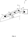
- FIG. 2 depicts a system 200 in accordance with one or more embodiments.
- the system 200 that is installed along at least one wing 201 extending from a fuselage 202 (e.g., of the aircraft 101, with the slat/flap control system 102 integrated therein).
- the system 200 includes a controller 211 (e.g., the computing device 120), one or more sensors 212 and 213 (e.g., the sensor 110), and wiring 214.
- the system 200 also includes a power drive unit 221, a driveline of rotating shafts 224 (e.g., of the slat/flap control system 102), one or more actuators 226.
- the power drive unit 221 provides torque to the one or more actuators 226 of the driveline of rotating shafts 224, which in turn move panels on the leading and trailing edges of the at least one wing 201.
- the one or more sensors 212 and 213 are sensing nodes spaced along the at least one wing 201 to detect and output torques and driveline temperatures (e.g., torque and temperature measurements) to the controller 211.
- the sensors 212 acquire at least one temperature input (e.g., a first driveline temperature for measuring skin temperature of a corresponding actuator 226) at least one torque input (e.g., first and second torques on each side of the corresponding actuator 226).
- the sensors 213 acquire at least one temperature input (e.g., a second driveline temperature for measuring skin temperature of the corresponding actuator 226) at least one torque input (e.g., a third torque of the corresponding actuator 226).
- the one or more sensors 212 and 213 can be a non-contact inductive encoder that measures relative angular position and torque (e.g., by measuring a phase shift between two resolvers having a sine output).
- Different non-contact inductive encoders include different mounting options and sizes that do not require motion to accurately report angular position.
- Non-contact inductive encoders can be manufactured up to several million counts per revolution for high-resolution angle/torque measurement.
- the non-contact inductive encoder can be a semi-wireless device where no wires are going to a rotor and one or more wires are going to a stator thereby offering distinct advantages over both wireless and wired sensors.
- each sensor 21 and 213 can include a pair of inductive encoders paired with sensors at a distal end of an outboard torque tubes of the corresponding actuator 226 on each side.
- a mounting flange extending outboard of a housing of the power drive unit 221 can be employed to allow a stator inductive encoder to be mounted close to rotor inductive encoder.
- a fixed (stator) portion can be added onto the housing, and/or a moving (rotor) portion can be added onto rotating portion of shaft of torque tube.
- the one or more sensors 212 and 213 can use a stationary element and a rotary element mounted nearby, where the stator/rotor combination gives a sine output to report position.
- the technical effects and benefits of the one or more sensors 212 and 213 include providing an increased reliability and improved maintenance, as battery concerns (e.g., battery life/power and thermal runway explosion) with respect to wireless strain gauges are eliminated, size and wear concerns (e.g., wear from friction against the rotating driveline) with respect to slip ring torque sensors are eliminated, and rotating wired connections of strain gauges are eliminated.
- battery concerns e.g., battery life/power and thermal runway explosion
- size and wear concerns e.g., wear from friction against the rotating driveline
- slip ring torque sensors are eliminated
- rotating wired connections of strain gauges are eliminated.
- non-contact inductive encoder can be used over alternative sensors that are bulky and/or heavy. Non-contact inductive encoders can, thus, provide cost savings by removing current skew sensors.
- the controller 211 (e.g., a computing device 120) utilizes the torque and temperature measurements for monitoring trends at an output of the power drive unit 221 output and to indicate if/when maintenance may be needed for the system 200.
- the controller 211 can receive the torque and temperature measurements from the one or more sensors 212 and 213 via the wiring 214 (e.g., installation of electric wiring supporting communications between the sensors 212 and 213 and the controller 211).
- the process flow 300 is an example operation of monitoring the power drive unit 221 by the system 200.
- the process flow 300 begins at block 310, where the power drive unit 221 operates.
- the power drive unit 221 provides torque to the one or more actuators 226 of the driveline of rotating shafts 224, which in turn move panels on the leading and trailing edges of the at least one wing 201.
- the one or more sensors 212 and 213 measure an angular position.
- the controller 211 by sending command communications across the wring 214, can cause the one or more sensors 212 and 213 to measure the angular position at one or more corresponding locations along the at least one wing 201.
- the angular position can be detected by detecting sinusoidal outputs of the one or more sensors 212 and 213 (e.g., of the inductive encoders).
- Torque of the power drive unit 221 and/or the one or more actuators 226 is calculated by measuring phase shift between the sinusoidal outputs (e.g., of the inboard and outboard inductive encoders).
- the angular position can be measured in real-time, so that real-time torque measurements can be calculated by the controller 211, which is in contrast to having passive torque limiters trip on a set torque value.
- the one or more sensors 212 and 213 measure a temperature.
- the controller 211 by sending command communications across the wring 214, can cause the one or more sensors 212 and 213 to measure the temperature at one or more corresponding locations along the at least one wing 201.
- the temperature can be detected be each of the one or more sensors 212 and 213 at a corresponding node location.
- the temperature can be measured in real-time, so that real-time temperature measurements can be associated with the real-time torque measurements by the controller 211.
- the one or more sensors 212 and 213 communicate the angular position and the temperature, as measurements, to the controller 211.
- the controller 211 can receive the measurements from the one or more sensors 212 and 213 via the wiring 214.
- the controller 211 analyzes the angular position and the temperature (e.g., measured data) to generate feedback information.
- the feedback information generated from the measured data provides the controller 211 with the underlying data to detect maintenance needs and to support developing more robust designs for next-generation systems. For instance, by measuring angular position with inductive encoder/node stations at multiple locations of the at least one wing 201, the system 200 (e.g., the controller 211) can calculate torques for various torque shafts to get torque monitoring at various points in the driveline of rotating shafts 224.
- the system 200 can enable torque monitoring at different temperatures and can link this monitoring to various phases of a flight cycle (e.g., taxing, idling, take-off, landing, cruising, etc.).
- the temperatures can define groups with the feedback information that the angular positions can be placed in, such that a single temperature range can define a flight cycle phase.
- temperature data could be used for new designs or optimization of existing designs, as actual temperatures seen by the system 200 during flight operations would be recorded.
- the controller 211 detects maintenance needs of the power drive unit 221 based on the feedback information. For example, in an event of a disconnect of the driveline of rotating shafts 224, relative position measurements on opposite sides of an actuator 226 can be used to diagnose a location of the disconnect. At present, in current slat/flap control systems, a disconnect cannot be isolated to a location.
Landscapes
- Engineering & Computer Science (AREA)
- Aviation & Aerospace Engineering (AREA)
- Microelectronics & Electronic Packaging (AREA)
- Power Engineering (AREA)
- Physics & Mathematics (AREA)
- General Physics & Mathematics (AREA)
- Testing Of Devices, Machine Parts, Or Other Structures Thereof (AREA)
Abstract
Description
- Exemplary embodiments pertain to slat/flap control systems used on aircrafts. In general, these slat/flap control systems do not have provisions for continuous electronic monitoring of driveline torque outboard of a power drive unit (PDU) of an aircraft or throughout a whole driveline of the aircraft. In some cases, passive torque limiters may be installed in actuators of the slat/flap control system or the driveline. Yet, the passive torque limiters only trip if exceeding a pre-defined value (e.g., a torque limit). Thus, torque values below the torque limit and exact magnitudes of jam torque for a torque limiter trip are not known to the slat/flap control system.
- In accordance with one or more embodiments, a method of monitoring a power drive unit installed on an aircraft is provided. The method includes causing, by a controller, sensors to measure an angular position at corresponding locations along at least one wing of the aircraft. The controller, as part of the method, receives the angular position from the one or more sensors and analyzes the angular position to generate feedback information to implement the monitoring of the power drive unit.
- In accordance with one or more embodiments or the method embodiment above, the angular position can be detected based on phase differences for torque of the power drive unit.
- In accordance with one or more embodiments or any of the method embodiments above, the angular position can be measured in real-time.
- In accordance with one or more embodiments or any of the method embodiments above, the one or more sensors can include non-contact inductive encoders that measures relative angular position and torque by measuring a phase shift between two resolvers.
- In accordance with one or more embodiments or any of the method embodiments above, the monitoring of the power drive unit can occur in real-time during operations of the power drive unit that provide torque to one or more actuators of a driveline of rotating shafts, which in turn move panels on leading and trailing edges of the at least one wing of the aircraft.
- In accordance with one or more embodiments or any of the method embodiments above, the controller can detect maintenance needs of the power drive unit based on the feedback information.
- In accordance with one or more embodiments or any of the method embodiments above, the monitoring of the power drive unit can include comparing calculate torques based on the angular position.
- In accordance with one or more embodiments or any of the method embodiments above, the monitoring of the power drive unit can include linking the feedback information to various phases of a flight cycle.
- In accordance with one or more embodiments or any of the method embodiments above, the controller can cause the one or more sensors to measure a temperature at the one or more corresponding locations, can receive the temperature from the one or more sensors, and can analyze the angular position and the temperature to generate the feedback information to implement the monitoring of the power drive unit.
- Any of the above method embodiments can be implemented as a system, computer program product, or an apparatus.
- The following descriptions should not be considered limiting in any way. With reference to the accompanying drawings, like elements are numbered alike:
-
FIG. 1 depicts a system in accordance with one or more embodiments; -
FIG. 2 depicts a system in accordance with one or more embodiments; and -
FIG. 3 depicts a process flow in accordance with one or more embodiments. - A detailed description of one or more embodiments of the disclosed apparatus and method are presented herein by way of exemplification and not limitation with reference to the Figures.
- Embodiments herein incorporate driveline inductive encoders and a distributed system of nodes along a driveline to determine/measure torques with respect to a slat/flap control system. The technical effects and benefits of the embodiments herein enable torque measurements to be used for diagnosing a location of a driveline disconnect, as well as for monitoring the torques in real-time. Torque and temperature measurements can also be captured and used to monitor torque trends at different temperatures to observe/identify anomalies (e.g., in support of development testing and characterizations of expected torques at various temperatures). In addition, technical effects and benefits of the embodiments herein support development testing and characterization of expected driveline torques at different temperatures (e.g., indicative of flight cycle phases), such that the passive torque limiters can possibly be removed to reduce weight and costs.
-
FIG. 1 depicts asystem 100 for implementing the teachings herein in accordance with one or more embodiments. Thesystem 100 is installed on anaircraft 101. Theaircraft 101 can be any machine capable of flight. Examples of theaircraft 101 include, but are not limited to, airplanes, helicopters, gliders, and drones, whether manned or unmanned vehicles. Theaircraft 101 can include a slat/flap control system 102 integrated therein. The slat/flap control system 102 includes a power drive unit, a driveline of rotating shafts, and panels. The panels can be on leading and trailing edges of aircraft wings (e.g., slats and flaps) that move in accordance with the driveline of rotating shafts, which receive torque from the power drive unit 2. - A portion of the
system 100 that is installed on theaircraft 101 includes one or more sensors 110 (e.g., generally referred to in the singular as the sensor 110) and one or more computing devices 120 (e.g., generally referred to in the singular as the computing device 120). The one ormore sensors 110 can be placed in a node arrangement with any number of sensing nodes being employed. Note that the number of sensing nodes is adjustable based on a layout of the slat/flap control system 102. - The
sensor 110 can be any transducer or combination of transducers capable of converting environmental activity and/or conditions into electrical signals. Examples of thesensor 110 include, but are not limited to, thermocouples, position devices, inductive sensors, accelerometers, visual-light cameras, strain gauges, and microphones. - The
computing device 120 has aprocessor 121, which can include one or more central processing units (CPUs). Theprocessor 121, also referred to as a processing circuit, microprocessor, computing unit, can be coupled via a system bus to asystem memory 122 and various other components. Thesystem memory 122 can include a read only memory (ROM) and/or a random access memory (RAM). - The
system memory 122 is an example of a tangible storage medium readable executable by theprocessor 121. Thesystem memory 122 storessoftware 124 anddata 125. Thesoftware 124 is stored as instructions for execution on thesystem 100 by the processor 121 (to perform process, such as the process flows ofFIG. 3 ). - The
software 124 can include code for monitoring torque trends over time (e.g., long-term health monitoring) and/or for detecting anomalies during a given flight cycle. For example, thesoftware 124 can provide real-time torque measurement and health monitoring for torque trends over life and temperature ranges for specific hardware or electronic architectures that are required to implement the slat/flap control system 102. - The
data 125 includes a set of values of qualitative or quantitative variables organized in various data structures to support and be used by operations of thesoftware 121. Examples of thedata 125 include, but are not limited to, angular position, temperature, and feedback information. Thus, as configured inFIG. 1 , the operations of thesoftware 124 and thedata 125 are necessarily rooted in the computational ability of theprocessor 121 to overcome and address the herein-described shortcomings of the slat/flap control systems. In this regard, thesoftware 124 and the data 25 improve computational operations of theprocessor 121 of thesystem 100 by enabling a torque and a driveline temperature to be detected and used for diagnosing a location of a driveline disconnect, as well as for enabling a monitoring of the torque in real-time and detecting torque trends at different temperatures to observe/identify anomalies (thereby increasing efficiency of the system 100). - The
computing device 120 includes one or more adapters 128 (e.g., generally referred to in the singular as the adapter 128) that interconnect and support communications between theprocessor 121, thesystem memory 122, and other components of the system 100 (e.g., the sensor 110). Examples of theadapter 128 include, but are not limited to, hard disk controllers, network adapters, communications adapter, graphics adapters, interface adapters, and display adapter. - The
computing device 120 can interconnect through anetwork 130 with other systems, devices, data, and software, such as aserver 140. Thenetwork 130 can be any type of communication environment providing physical, electronic, and virtual connections therein. Thenetwork 130 can include one or more of a local area network (LAN), a wide area network (WAN), a wireless network, a telecommunication network, and the Internet. Like thecomputing device 120, the server includes aprocessor 141 and a memory 142 (as described here). In one or more embodiments of the present invention, the operations of thesoftware 124 and thedata 125 can be implemented on thenetwork 130 by theserver 140. For instance, thenetwork 130 and theserver 140 can combine to provide internal iterations of thesoftware 124 and thedata 125 as a platform as a service, a software as a service, and/or infrastructure as a service (e.g., as a web application in a distributed system). -
FIG. 2 depicts asystem 200 in accordance with one or more embodiments. Thesystem 200 that is installed along at least onewing 201 extending from a fuselage 202 (e.g., of theaircraft 101, with the slat/flap control system 102 integrated therein). Thesystem 200 includes a controller 211 (e.g., the computing device 120), one ormore sensors 212 and 213 (e.g., the sensor 110), andwiring 214. Thesystem 200 also includes apower drive unit 221, a driveline of rotating shafts 224 (e.g., of the slat/flap control system 102), one ormore actuators 226. Thepower drive unit 221 provides torque to the one ormore actuators 226 of the driveline of rotatingshafts 224, which in turn move panels on the leading and trailing edges of the at least onewing 201. - The one or
more sensors wing 201 to detect and output torques and driveline temperatures (e.g., torque and temperature measurements) to thecontroller 211. In accordance with one or more embodiments, thesensors 212 acquire at least one temperature input (e.g., a first driveline temperature for measuring skin temperature of a corresponding actuator 226) at least one torque input (e.g., first and second torques on each side of the corresponding actuator 226). Thesensors 213 acquire at least one temperature input (e.g., a second driveline temperature for measuring skin temperature of the corresponding actuator 226) at least one torque input (e.g., a third torque of the corresponding actuator 226). - In accordance with one or more embodiments, the one or
more sensors - Further, each
sensor 21 and 213 can include a pair of inductive encoders paired with sensors at a distal end of an outboard torque tubes of thecorresponding actuator 226 on each side. A mounting flange extending outboard of a housing of thepower drive unit 221 can be employed to allow a stator inductive encoder to be mounted close to rotor inductive encoder. In other embodiments, a fixed (stator) portion can be added onto the housing, and/or a moving (rotor) portion can be added onto rotating portion of shaft of torque tube. - In this way, the one or
more sensors more sensors - The controller 211 (e.g., a computing device 120) utilizes the torque and temperature measurements for monitoring trends at an output of the
power drive unit 221 output and to indicate if/when maintenance may be needed for thesystem 200. Thecontroller 211 can receive the torque and temperature measurements from the one ormore sensors sensors - Turning now to
FIG. 3 , aprocess flow 300 is depicted in accordance with one or more embodiments. Theprocess flow 300 is an example operation of monitoring thepower drive unit 221 by thesystem 200. Theprocess flow 300 begins atblock 310, where thepower drive unit 221 operates. In this regard, thepower drive unit 221 provides torque to the one ormore actuators 226 of the driveline of rotatingshafts 224, which in turn move panels on the leading and trailing edges of the at least onewing 201. - At
block 320, the one ormore sensors controller 211, by sending command communications across the wring 214, can cause the one ormore sensors wing 201. The angular position can be detected by detecting sinusoidal outputs of the one ormore sensors 212 and 213 (e.g., of the inductive encoders). Torque of thepower drive unit 221 and/or the one ormore actuators 226 is calculated by measuring phase shift between the sinusoidal outputs (e.g., of the inboard and outboard inductive encoders). The angular position can be measured in real-time, so that real-time torque measurements can be calculated by thecontroller 211, which is in contrast to having passive torque limiters trip on a set torque value. - At
block 330, the one ormore sensors controller 211, by sending command communications across the wring 214, can cause the one ormore sensors wing 201. The temperature can be detected be each of the one ormore sensors controller 211. - At
block 340, the one ormore sensors controller 211. Thecontroller 211 can receive the measurements from the one ormore sensors wiring 214. - At
block 350, thecontroller 211 analyzes the angular position and the temperature (e.g., measured data) to generate feedback information. The feedback information generated from the measured data provides thecontroller 211 with the underlying data to detect maintenance needs and to support developing more robust designs for next-generation systems. For instance, by measuring angular position with inductive encoder/node stations at multiple locations of the at least onewing 201, the system 200 (e.g., the controller 211) can calculate torques for various torque shafts to get torque monitoring at various points in the driveline of rotatingshafts 224. Further, by measuring temperatures, the system 200 (e.g., the controller 211) can enable torque monitoring at different temperatures and can link this monitoring to various phases of a flight cycle (e.g., taxing, idling, take-off, landing, cruising, etc.). For instance, the temperatures can define groups with the feedback information that the angular positions can be placed in, such that a single temperature range can define a flight cycle phase. Thus, temperature data could be used for new designs or optimization of existing designs, as actual temperatures seen by thesystem 200 during flight operations would be recorded. - At
block 360, thecontroller 211 detects maintenance needs of thepower drive unit 221 based on the feedback information. For example, in an event of a disconnect of the driveline of rotatingshafts 224, relative position measurements on opposite sides of anactuator 226 can be used to diagnose a location of the disconnect. At present, in current slat/flap control systems, a disconnect cannot be isolated to a location. - The term "about" is intended to include the degree of error associated with measurement of the particular quantity based upon the equipment available at the time of filing the application.
- The terminology used herein is for the purpose of describing particular embodiments only and is not intended to be limiting of the present disclosure. As used herein, the singular forms "a", "an" and "the" are intended to include the plural forms as well, unless the context clearly indicates otherwise. It will be further understood that the terms "comprises" and/or "comprising," when used in this specification, specify the presence of stated features, integers, steps, operations, elements, and/or components, but do not preclude the presence or addition of one or more other features, integers, steps, operations, element components, and/or groups thereof.
- While the present disclosure has been described with reference to an exemplary embodiment or embodiments, it will be understood by those skilled in the art that various changes may be made and equivalents may be substituted for elements thereof without departing from the scope of the invention as defined by the claims. In addition, many modifications may be made to adapt a particular situation or material to the teachings of the present disclosure without departing from the scope of the invention. Therefore, it is intended that the present disclosure not be limited to the particular embodiment disclosed as the best mode contemplated for carrying out this present disclosure, but that the present disclosure will include all embodiments falling within the scope of the claims.
Claims (15)
- A method of monitoring a power drive unit installed on an aircraft, the method comprising:causing, by a controller (211), one or more sensors (110, 212, 213) to measure an angular position at one or more corresponding locations along at least one wing (201) of the aircraft (101);receiving, from the one or more sensors by the controller, the angular position; andanalyzing, by the controller, the angular position to generate feedback information to implement the monitoring of the power drive unit.
- The method of claim 1, wherein the angular position is detected based on phase differences for torque of the power drive unit.
- The method of claim 1 or 2, wherein the angular position is measured in real-time.
- The method of any preceding claim, wherein the one or more sensors include non-contact inductive encoders that measures relative angular position and torque by measuring a phase shift between two resolvers.
- The method of any preceding claim, wherein the monitoring of the power drive unit (221) occurs in real-time during operations of the power drive unit that provide torque to one or more actuators (226) of a driveline of rotating shafts (224), which in turn move panels on leading and trailing edges of the at least one wing of the aircraft (101).
- The method of any preceding claim, wherein the controller detects maintenance needs of the power drive unit based on the feedback information.
- The method of any preceding claim, wherein the monitoring of the power drive unit includes comparing calculate torques based on the angular position.
- The method of any preceding claim, wherein the monitoring of the power drive unit includes linking the feedback information to various phases of a flight cycle.
- The method of any preceding claim, wherein the controller causes the one or more sensors to measure a temperature at the one or more corresponding locations, receives the temperature from the one or more sensors, and analyzes the angular position and the temperature to generate the feedback information to implement the monitoring of the power drive unit.
- A system comprising:a power drive unit (221) installed on an aircraft (101);a controller (211);one or more sensors (212, 213),wherein the system monitors the power drive unit by:causing the one or more sensors to measure an angular position at one or more corresponding locations along at least one wing of the aircraft,receiving, from the one or more sensors by the controller, the angular position, andanalyzing, by the controller, the angular position to generate feedback information to implement the monitoring of the power drive unit.
- The system of claim 10, wherein the angular position is detected based on phase differences for torque of the power drive unit, and/or wherein the angular position are measured in real-time.
- The system of claim 10 or 11, wherein the one or more sensors (212, 213) include non-contact inductive encoders that measures relative angular position and torque by measuring a phase shift between two resolvers.
- The system of claim 10, 11 or 12 wherein the monitoring of the power drive unit occurs in real-time during operations of the power drive unit that provide torque to one or more actuators (226) of a driveline of rotating shafts (224), which in turn move panels on leading and trailing edges of the at least one wing of the aircraft.
- The system of any of claims 10 to 13, wherein the monitoring of the power drive unit includes comparing calculate torques based on the angular position and/or wherein the monitoring of the power drive unit includes linking the feedback information to various phases of a flight cycle.
- The system of any of claims 10 to 14, wherein the controller causes the one or more sensors to measure a temperature at the one or more corresponding locations, receives the temperature from the one or more sensors, and analyzes the angular position and the temperature to generate the feedback information to implement the monitoring of the power drive unit.
Applications Claiming Priority (1)
| Application Number | Priority Date | Filing Date | Title |
|---|---|---|---|
| US16/663,812 US11485476B2 (en) | 2019-10-25 | 2019-10-25 | Driveline torque monitoring for long-term health assessment |
Publications (2)
| Publication Number | Publication Date |
|---|---|
| EP3812265A1 true EP3812265A1 (en) | 2021-04-28 |
| EP3812265B1 EP3812265B1 (en) | 2025-10-08 |
Family
ID=68731785
Family Applications (1)
| Application Number | Title | Priority Date | Filing Date |
|---|---|---|---|
| EP19212050.9A Active EP3812265B1 (en) | 2019-10-25 | 2019-11-28 | Driveline torque monitoring for long-term health assessment |
Country Status (3)
| Country | Link |
|---|---|
| US (1) | US11485476B2 (en) |
| EP (1) | EP3812265B1 (en) |
| CA (1) | CA3064625A1 (en) |
Families Citing this family (1)
| Publication number | Priority date | Publication date | Assignee | Title |
|---|---|---|---|---|
| US11697510B2 (en) * | 2020-01-30 | 2023-07-11 | The Boeing Company | Monitoring health of safety brakes in auxiliary lift devices |
Citations (7)
| Publication number | Priority date | Publication date | Assignee | Title |
|---|---|---|---|---|
| US20140015520A1 (en) * | 2012-07-16 | 2014-01-16 | Honeywell International Inc. | 180-degree arc position encoder with an extended angular position sensing range |
| EP2695810A1 (en) * | 2012-08-09 | 2014-02-12 | Airbus Operations GmbH | Drive system for control surfaces of an aircraft |
| EP3012191A1 (en) * | 2014-10-24 | 2016-04-27 | Airbus Operations GmbH | Method for determining a state of a component in a high lift system of an aircraft, high lift system of an aircraft and aircraft having such a high lift system |
| EP3078596A1 (en) * | 2015-04-09 | 2016-10-12 | The Boeing Company | Aircraft wing slat skew detection systems and methods |
| US20190061531A1 (en) * | 2017-08-25 | 2019-02-28 | Hamilton Sundstrand Corporation | Flight control system regenerative braking |
| EP3459858A1 (en) * | 2017-09-25 | 2019-03-27 | Hamilton Sundstrand Corporation | Prognostic health monitoring for use with an aircraft |
| US20190308718A1 (en) * | 2018-04-06 | 2019-10-10 | Goodrich Actuation Systems Limited | Hydraulic power drive unit |
Family Cites Families (13)
| Publication number | Priority date | Publication date | Assignee | Title |
|---|---|---|---|---|
| US5686907A (en) * | 1995-05-15 | 1997-11-11 | The Boeing Company | Skew and loss detection system for individual high lift devices |
| US7307415B2 (en) | 2002-02-14 | 2007-12-11 | Bvr Technologies Co. | Contactless angular position sensor and method for sensing angular position of a rotatable shaft |
| US7322250B1 (en) | 2002-04-09 | 2008-01-29 | Rockwell Automation Technologies, Inc. | System and method for sensing torque on a rotating shaft |
| US7114601B2 (en) | 2003-04-14 | 2006-10-03 | Curtiss-Wright Controls, Inc. | Torque transfer limiting arrangement for a rotational drive shaft |
| DE102005058192A1 (en) | 2005-12-06 | 2007-06-28 | Airbus Deutschland Gmbh | Device for fault detection of adjustable flaps |
| FR2924538B1 (en) | 2007-11-30 | 2010-01-22 | Sagem Defense Securite | METHOD FOR MONITORING THE PERFORMANCE OF AN ELECTROMECHANICAL ACTUATOR OF THE ROTOLINE TYPE |
| EP2420803A1 (en) * | 2010-08-13 | 2012-02-22 | BALLUFF GmbH | Device for recording the torsion angle of a shaft and/or the torque of a shaft and method for operating the device |
| EP2523009B1 (en) * | 2011-05-12 | 2015-01-28 | ABB Technology AG | Method and apparatus for monitoring the condition of electromechanical systems |
| US9520820B2 (en) * | 2014-12-23 | 2016-12-13 | Deere & Company | Method and apparatus for auto-tuning an electric machine current regulator |
| DE102016015382B4 (en) | 2016-12-22 | 2025-02-06 | Liebherr-Aerospace Lindenberg Gmbh | Actuator for operating a device of an aircraft |
| US10473163B2 (en) * | 2017-08-22 | 2019-11-12 | Hamilton Sundstrand Corporation | Torque-limiter health monitoring |
| EP3713844A1 (en) | 2017-11-21 | 2020-09-30 | Bombardier Inc. | System and method for actuating high-lift flight control surfaces |
| US10955302B2 (en) * | 2018-10-12 | 2021-03-23 | Deere & Company | Torque determination system and method |
-
2019
- 2019-10-25 US US16/663,812 patent/US11485476B2/en active Active
- 2019-11-28 EP EP19212050.9A patent/EP3812265B1/en active Active
- 2019-12-10 CA CA3064625A patent/CA3064625A1/en active Pending
Patent Citations (7)
| Publication number | Priority date | Publication date | Assignee | Title |
|---|---|---|---|---|
| US20140015520A1 (en) * | 2012-07-16 | 2014-01-16 | Honeywell International Inc. | 180-degree arc position encoder with an extended angular position sensing range |
| EP2695810A1 (en) * | 2012-08-09 | 2014-02-12 | Airbus Operations GmbH | Drive system for control surfaces of an aircraft |
| EP3012191A1 (en) * | 2014-10-24 | 2016-04-27 | Airbus Operations GmbH | Method for determining a state of a component in a high lift system of an aircraft, high lift system of an aircraft and aircraft having such a high lift system |
| EP3078596A1 (en) * | 2015-04-09 | 2016-10-12 | The Boeing Company | Aircraft wing slat skew detection systems and methods |
| US20190061531A1 (en) * | 2017-08-25 | 2019-02-28 | Hamilton Sundstrand Corporation | Flight control system regenerative braking |
| EP3459858A1 (en) * | 2017-09-25 | 2019-03-27 | Hamilton Sundstrand Corporation | Prognostic health monitoring for use with an aircraft |
| US20190308718A1 (en) * | 2018-04-06 | 2019-10-10 | Goodrich Actuation Systems Limited | Hydraulic power drive unit |
Also Published As
| Publication number | Publication date |
|---|---|
| EP3812265B1 (en) | 2025-10-08 |
| US20210122457A1 (en) | 2021-04-29 |
| US11485476B2 (en) | 2022-11-01 |
| CA3064625A1 (en) | 2021-04-25 |
| BR102019026017A2 (en) | 2021-05-04 |
Similar Documents
| Publication | Publication Date | Title |
|---|---|---|
| US9233763B1 (en) | Methods and systems for aircraft systems health trend monitoring | |
| EP3739342B1 (en) | Prognostic monitoring of complementary air data system sensors | |
| EP3284671B1 (en) | Diagnostic method, system and device for a rotorcraft drive system | |
| EP3401660B1 (en) | Propeller health monitoring | |
| US9240083B2 (en) | Rotor system health monitoring using shaft load measurements and virtual monitoring of loads | |
| US11932414B2 (en) | Method and system for enabling component monitoring redundancy in a digital network of intelligent sensing devices | |
| EP3126243B1 (en) | System and method for improved drive system diagnostics | |
| EP3012191B1 (en) | Method for determining a state of a component in a high lift system of an aircraft, high lift system of an aircraft and aircraft having such a high lift system | |
| EP3232382A1 (en) | Physical component predicted remainig useful life | |
| CN106970642A (en) | A kind of multi-rotor unmanned aerial vehicle state monitoring apparatus | |
| EP2905224B1 (en) | Rotor state sensor system | |
| US20190308721A1 (en) | Integrated smart sensing systems and methods | |
| US11485476B2 (en) | Driveline torque monitoring for long-term health assessment | |
| CN206656739U (en) | A kind of depopulated helicopter state monitoring apparatus | |
| CN114514483B (en) | Event-oriented transmission of process measurements | |
| EP3355033A1 (en) | Fault tolerance sensor interface | |
| EP3126233B1 (en) | Rotor wireless load and motion monitoring sensor network | |
| BR102019026017B1 (en) | METHOD AND SYSTEM FOR MONITORING A POWER DRIVE UNIT INSTALLED IN AN AIRCRAFT | |
| US20150051868A1 (en) | System for monitoring rotating elements | |
| CN106996794A (en) | A kind of depopulated helicopter state monitoring apparatus | |
| CN114450647B (en) | Diagnostics of technical systems | |
| EP4264206B1 (en) | Method and system for determining vibrations generated by a device | |
| Vechart et al. | Fleetwide Integrated Prognostics Health Management for Emerging EVTOL Operations | |
| Kumar et al. | PREDICTIVE MOTOR HEALTH MONITORING SYSTEM USING VIBRATION AND TEMPERATURE ANALYSIS VIA IOT | |
| CN111470067A (en) | Series hybrid power system fault diagnosis system and method based on model prediction |
Legal Events
| Date | Code | Title | Description |
|---|---|---|---|
| PUAI | Public reference made under article 153(3) epc to a published international application that has entered the european phase |
Free format text: ORIGINAL CODE: 0009012 |
|
| STAA | Information on the status of an ep patent application or granted ep patent |
Free format text: STATUS: THE APPLICATION HAS BEEN PUBLISHED |
|
| AK | Designated contracting states |
Kind code of ref document: A1 Designated state(s): AL AT BE BG CH CY CZ DE DK EE ES FI FR GB GR HR HU IE IS IT LI LT LU LV MC MK MT NL NO PL PT RO RS SE SI SK SM TR |
|
| AX | Request for extension of the european patent |
Extension state: BA ME |
|
| STAA | Information on the status of an ep patent application or granted ep patent |
Free format text: STATUS: REQUEST FOR EXAMINATION WAS MADE |
|
| 17P | Request for examination filed |
Effective date: 20211028 |
|
| RBV | Designated contracting states (corrected) |
Designated state(s): AL AT BE BG CH CY CZ DE DK EE ES FI FR GB GR HR HU IE IS IT LI LT LU LV MC MK MT NL NO PL PT RO RS SE SI SK SM TR |
|
| STAA | Information on the status of an ep patent application or granted ep patent |
Free format text: STATUS: EXAMINATION IS IN PROGRESS |
|
| 17Q | First examination report despatched |
Effective date: 20230321 |
|
| RIC1 | Information provided on ipc code assigned before grant |
Ipc: G01L 3/10 20060101ALN20240522BHEP Ipc: B64D 45/00 20060101ALN20240522BHEP Ipc: B64C 9/00 20060101ALN20240522BHEP Ipc: B64C 3/38 20060101ALN20240522BHEP Ipc: B64C 13/00 20060101AFI20240522BHEP |
|
| GRAP | Despatch of communication of intention to grant a patent |
Free format text: ORIGINAL CODE: EPIDOSNIGR1 |
|
| RIC1 | Information provided on ipc code assigned before grant |
Ipc: G01L 3/10 20060101ALN20250312BHEP Ipc: B64D 45/00 20060101ALN20250312BHEP Ipc: B64C 9/00 20060101ALN20250312BHEP Ipc: B64C 3/38 20060101ALN20250312BHEP Ipc: B64C 13/00 20060101AFI20250312BHEP |
|
| STAA | Information on the status of an ep patent application or granted ep patent |
Free format text: STATUS: GRANT OF PATENT IS INTENDED |
|
| RIC1 | Information provided on ipc code assigned before grant |
Ipc: G01L 3/10 20060101ALN20250318BHEP Ipc: B64D 45/00 20060101ALN20250318BHEP Ipc: B64C 9/00 20060101ALN20250318BHEP Ipc: B64C 3/38 20060101ALN20250318BHEP Ipc: B64C 13/00 20060101AFI20250318BHEP |
|
| RIC1 | Information provided on ipc code assigned before grant |
Ipc: G01L 3/10 20060101ALN20250325BHEP Ipc: B64D 45/00 20060101ALN20250325BHEP Ipc: B64C 9/00 20060101ALN20250325BHEP Ipc: B64C 3/38 20060101ALN20250325BHEP Ipc: B64C 13/00 20060101AFI20250325BHEP |
|
| RIC1 | Information provided on ipc code assigned before grant |
Ipc: G01L 3/10 20060101ALN20250402BHEP Ipc: B64D 45/00 20060101ALN20250402BHEP Ipc: B64C 9/00 20060101ALN20250402BHEP Ipc: B64C 3/38 20060101ALN20250402BHEP Ipc: B64C 13/00 20060101AFI20250402BHEP |
|
| INTG | Intention to grant announced |
Effective date: 20250416 |
|
| GRAS | Grant fee paid |
Free format text: ORIGINAL CODE: EPIDOSNIGR3 |
|
| GRAA | (expected) grant |
Free format text: ORIGINAL CODE: 0009210 |
|
| STAA | Information on the status of an ep patent application or granted ep patent |
Free format text: STATUS: THE PATENT HAS BEEN GRANTED |
|
| AK | Designated contracting states |
Kind code of ref document: B1 Designated state(s): AL AT BE BG CH CY CZ DE DK EE ES FI FR GB GR HR HU IE IS IT LI LT LU LV MC MK MT NL NO PL PT RO RS SE SI SK SM TR |
|
| REG | Reference to a national code |
Ref country code: GB Ref legal event code: FG4D Ref country code: CH Ref legal event code: F10 Free format text: ST27 STATUS EVENT CODE: U-0-0-F10-F00 (AS PROVIDED BY THE NATIONAL OFFICE) Effective date: 20251008 |
|
| REG | Reference to a national code |
Ref country code: DE Ref legal event code: R096 Ref document number: 602019076587 Country of ref document: DE |
|
| REG | Reference to a national code |
Ref country code: IE Ref legal event code: FG4D |
|
| PGFP | Annual fee paid to national office [announced via postgrant information from national office to epo] |
Ref country code: GB Payment date: 20251226 Year of fee payment: 7 |
|
| PGFP | Annual fee paid to national office [announced via postgrant information from national office to epo] |
Ref country code: IT Payment date: 20251105 Year of fee payment: 7 |
|
| PGFP | Annual fee paid to national office [announced via postgrant information from national office to epo] |
Ref country code: FR Payment date: 20251128 Year of fee payment: 7 |
|
| REG | Reference to a national code |
Ref country code: NL Ref legal event code: MP Effective date: 20251008 |
|
| REG | Reference to a national code |
Ref country code: AT Ref legal event code: MK05 Ref document number: 1844632 Country of ref document: AT Kind code of ref document: T Effective date: 20251008 |
|
| PG25 | Lapsed in a contracting state [announced via postgrant information from national office to epo] |
Ref country code: NL Free format text: LAPSE BECAUSE OF FAILURE TO SUBMIT A TRANSLATION OF THE DESCRIPTION OR TO PAY THE FEE WITHIN THE PRESCRIBED TIME-LIMIT Effective date: 20251008 |
|
| PG25 | Lapsed in a contracting state [announced via postgrant information from national office to epo] |
Ref country code: ES Free format text: LAPSE BECAUSE OF FAILURE TO SUBMIT A TRANSLATION OF THE DESCRIPTION OR TO PAY THE FEE WITHIN THE PRESCRIBED TIME-LIMIT Effective date: 20251008 |
|
| REG | Reference to a national code |
Ref country code: LT Ref legal event code: MG9D |
|
| PG25 | Lapsed in a contracting state [announced via postgrant information from national office to epo] |
Ref country code: NO Free format text: LAPSE BECAUSE OF FAILURE TO SUBMIT A TRANSLATION OF THE DESCRIPTION OR TO PAY THE FEE WITHIN THE PRESCRIBED TIME-LIMIT Effective date: 20260108 |
|
| PGFP | Annual fee paid to national office [announced via postgrant information from national office to epo] |
Ref country code: DE Payment date: 20251231 Year of fee payment: 7 |
|
| PG25 | Lapsed in a contracting state [announced via postgrant information from national office to epo] |
Ref country code: FI Free format text: LAPSE BECAUSE OF FAILURE TO SUBMIT A TRANSLATION OF THE DESCRIPTION OR TO PAY THE FEE WITHIN THE PRESCRIBED TIME-LIMIT Effective date: 20251008 Ref country code: AT Free format text: LAPSE BECAUSE OF FAILURE TO SUBMIT A TRANSLATION OF THE DESCRIPTION OR TO PAY THE FEE WITHIN THE PRESCRIBED TIME-LIMIT Effective date: 20251008 Ref country code: HR Free format text: LAPSE BECAUSE OF FAILURE TO SUBMIT A TRANSLATION OF THE DESCRIPTION OR TO PAY THE FEE WITHIN THE PRESCRIBED TIME-LIMIT Effective date: 20251008 |
|
| PG25 | Lapsed in a contracting state [announced via postgrant information from national office to epo] |
Ref country code: RS Free format text: LAPSE BECAUSE OF FAILURE TO SUBMIT A TRANSLATION OF THE DESCRIPTION OR TO PAY THE FEE WITHIN THE PRESCRIBED TIME-LIMIT Effective date: 20260108 |
|
| PG25 | Lapsed in a contracting state [announced via postgrant information from national office to epo] |
Ref country code: IS Free format text: LAPSE BECAUSE OF FAILURE TO SUBMIT A TRANSLATION OF THE DESCRIPTION OR TO PAY THE FEE WITHIN THE PRESCRIBED TIME-LIMIT Effective date: 20260208 |
|
| PG25 | Lapsed in a contracting state [announced via postgrant information from national office to epo] |
Ref country code: PT Free format text: LAPSE BECAUSE OF FAILURE TO SUBMIT A TRANSLATION OF THE DESCRIPTION OR TO PAY THE FEE WITHIN THE PRESCRIBED TIME-LIMIT Effective date: 20260209 |
|
| PG25 | Lapsed in a contracting state [announced via postgrant information from national office to epo] |
Ref country code: PL Free format text: LAPSE BECAUSE OF FAILURE TO SUBMIT A TRANSLATION OF THE DESCRIPTION OR TO PAY THE FEE WITHIN THE PRESCRIBED TIME-LIMIT Effective date: 20251008 |
|
| PG25 | Lapsed in a contracting state [announced via postgrant information from national office to epo] |
Ref country code: LV Free format text: LAPSE BECAUSE OF FAILURE TO SUBMIT A TRANSLATION OF THE DESCRIPTION OR TO PAY THE FEE WITHIN THE PRESCRIBED TIME-LIMIT Effective date: 20251008 |
|
| PG25 | Lapsed in a contracting state [announced via postgrant information from national office to epo] |
Ref country code: BG Free format text: LAPSE BECAUSE OF FAILURE TO SUBMIT A TRANSLATION OF THE DESCRIPTION OR TO PAY THE FEE WITHIN THE PRESCRIBED TIME-LIMIT Effective date: 20251008 |