EP3812253A1 - Straddled electric vehicle - Google Patents
Straddled electric vehicle Download PDFInfo
- Publication number
- EP3812253A1 EP3812253A1 EP20202779.3A EP20202779A EP3812253A1 EP 3812253 A1 EP3812253 A1 EP 3812253A1 EP 20202779 A EP20202779 A EP 20202779A EP 3812253 A1 EP3812253 A1 EP 3812253A1
- Authority
- EP
- European Patent Office
- Prior art keywords
- motor
- battery
- rotation shaft
- mounting portion
- drive unit
- Prior art date
- Legal status (The legal status is an assumption and is not a legal conclusion. Google has not performed a legal analysis and makes no representation as to the accuracy of the status listed.)
- Granted
Links
Images






Classifications
-
- B—PERFORMING OPERATIONS; TRANSPORTING
- B62—LAND VEHICLES FOR TRAVELLING OTHERWISE THAN ON RAILS
- B62M—RIDER PROPULSION OF WHEELED VEHICLES OR SLEDGES; POWERED PROPULSION OF SLEDGES OR SINGLE-TRACK CYCLES; TRANSMISSIONS SPECIALLY ADAPTED FOR SUCH VEHICLES
- B62M7/00—Motorcycles characterised by position of motor or engine
- B62M7/02—Motorcycles characterised by position of motor or engine with engine between front and rear wheels
- B62M7/06—Motorcycles characterised by position of motor or engine with engine between front and rear wheels directly under the saddle or seat
-
- B—PERFORMING OPERATIONS; TRANSPORTING
- B62—LAND VEHICLES FOR TRAVELLING OTHERWISE THAN ON RAILS
- B62J—CYCLE SADDLES OR SEATS; AUXILIARY DEVICES OR ACCESSORIES SPECIALLY ADAPTED TO CYCLES AND NOT OTHERWISE PROVIDED FOR, e.g. ARTICLE CARRIERS OR CYCLE PROTECTORS
- B62J43/00—Arrangements of batteries
- B62J43/10—Arrangements of batteries for propulsion
- B62J43/16—Arrangements of batteries for propulsion on motorcycles or the like
-
- B—PERFORMING OPERATIONS; TRANSPORTING
- B62—LAND VEHICLES FOR TRAVELLING OTHERWISE THAN ON RAILS
- B62J—CYCLE SADDLES OR SEATS; AUXILIARY DEVICES OR ACCESSORIES SPECIALLY ADAPTED TO CYCLES AND NOT OTHERWISE PROVIDED FOR, e.g. ARTICLE CARRIERS OR CYCLE PROTECTORS
- B62J9/00—Containers specially adapted for cycles, e.g. panniers or saddle bags
- B62J9/10—Containers specially adapted for cycles, e.g. panniers or saddle bags integrated with the cycle
- B62J9/14—Containers specially adapted for cycles, e.g. panniers or saddle bags integrated with the cycle under the saddle
-
- B—PERFORMING OPERATIONS; TRANSPORTING
- B62—LAND VEHICLES FOR TRAVELLING OTHERWISE THAN ON RAILS
- B62K—CYCLES; CYCLE FRAMES; CYCLE STEERING DEVICES; RIDER-OPERATED TERMINAL CONTROLS SPECIALLY ADAPTED FOR CYCLES; CYCLE AXLE SUSPENSIONS; CYCLE SIDECARS, FORECARS, OR THE LIKE
- B62K2202/00—Motorised scooters
-
- B—PERFORMING OPERATIONS; TRANSPORTING
- B62—LAND VEHICLES FOR TRAVELLING OTHERWISE THAN ON RAILS
- B62K—CYCLES; CYCLE FRAMES; CYCLE STEERING DEVICES; RIDER-OPERATED TERMINAL CONTROLS SPECIALLY ADAPTED FOR CYCLES; CYCLE AXLE SUSPENSIONS; CYCLE SIDECARS, FORECARS, OR THE LIKE
- B62K2204/00—Adaptations for driving cycles by electric motor
Definitions
- the present invention relates to a straddled electric vehicle.
- An electric two-wheeled vehicle includes an electric motor and a battery that stores power to be supplied to the electric motor.
- the case containing the electric motor is disposed behind the battery and below the seat.
- Two mounting portions are respectively provided on the upper and lower portions of the case, and the case is attached to the body frame at the two mounting portions.
- the space formed between the electric motor and the seat is effectively utilized.
- a battery is disposed in this space.
- a storage case for storing equipment such as a helmet is disposed in the space. If this space can be increased, the capacity of the battery disposed therein can be increased, or the capacity of the storage case can be increased.
- a straddled electric vehicle proposed in this embodiment will be described.
- an electric two-wheeled vehicle 1 shown in drawings such as FIG. 1 will be described.
- the straddled electric vehicle may be a four-wheeled or three-wheeled electric vehicle having a seat on which a rider straddles and sits.
- directions indicated by X1 and X2 are referred to as a right direction and a left direction, respectively, and directions indicated by Z1 and Z2 are referred to as an upward direction and a downward direction, respectively.
- the directions Y1 and Y2 shown in FIG. 2 are referred to as a forward direction and a rearward direction, respectively.
- the direction indicated by X1-X2 is referred to as a vehicle width direction or a vehicle left-right direction.
- the direction indicated by Y1-Y2 is referred to as a vehicle longitudinal direction or a vehicle front-rear direction.
- the direction indicated by Z1-Z2 is referred to as a vehicle vertical direction or a vehicle up-down direction.
- the electric two-wheeled vehicle 1 has a front wheel 2, a rear wheel 3, a steering handle 5 for steering the front wheel 2, and a seat 6 (see FIG. 1 ) disposed behind the steering handle 5.
- the electric two-wheeled vehicle 1 has a rear arm 9 connected to a body frame 20 via a pivot 29. The rear portion of the rear arm 9 is connected to the axle of the rear wheel 3.
- the electric two-wheeled vehicle 1 has a rear cushion 11 connected to the rear arm 9 and the body frame 20. The lower end of the rear cushion 11 is connected to the rear arm 9, and the upper end of the rear arm 9 is connected to the body frame 20 (more specifically, a frame rear portion 21C to be described later).
- the body frame 20 has, at its foremost portion, a head pipe 22 supporting a steering shaft to which the steering handle 5 is connected.
- the left and right front cushions 8 are connected to the lower portion of the steering shaft, and the front wheel 2 is supported by the lower end of the front cushions 8.
- the body frame 20 has a right portion 21R (see FIG. 4A ) and a left portion 21L (see FIG. 4A ). As shown in FIG. 2 , each of the right portion 21R and the left portion 21L includes a frame front portion 21A extending downward from the head pipe 22, a frame lower portion 21B extending rearward from the frame front portion 21A and disposed in the lower body, and a frame rear portion 21C extending obliquely rearward and upward from the frame lower portion 21B.
- the three portions 21A, 21B, and 21C may be formed of a single pipe, or a plurality of pipes connected to each other.
- the right portion 21R and the left portion 21L of the body frame 20 has a frame upper portion 21D.
- the frame upper portion 21D extends rearward from the middle of the frame front portion 21A, and is away upward from the frame lower portion 21B in a side view of the vehicle body.
- the upper portion of the frame rear portion 21C is connected to the rear portion of the frame upper portion 21D.
- the seat 6 is supported on the upper side of the rear portion of the frame upper portion 21D.
- the electric two-wheeled vehicle 1 includes a battery 50, a motor unit 40, and a motor drive unit 30.
- the battery 50 includes a plurality of battery cells and a controller for controlling the charging and discharging of the battery 50.
- the battery 50 has a battery housing 51 containing the battery cells and the controller.
- the battery 50 is, for example, a lithium ion battery.
- the motor unit 40 includes an electric motor 41 (see FIG. 8 ) and a case 46 containing the electric motor 41.
- the electric motor 41 is a driving source of the electric two-wheeled vehicle 1, and its rotation is transmitted to the rear wheel 3.
- the motor unit 40 has a speed reduction mechanism 42 (see FIG. 8 ).
- the speed reduction mechanism 42 is also housed in the case 46.
- the case 46 has, for example, a right housing portion 46h containing the electric motor 41 and a left housing portion 46i containing the speed reduction mechanism 42.
- the inside of the right housing portion 46h and the inside of the left housing portion 46i may be partitioned.
- the motor unit 40 includes a first rotation shaft 43 (see FIG. 8 ) at the rotation center Cm of the electric motor 41, and a second rotation shaft 44 (see FIG. 8 ) radially away from the first rotation shaft 43 of the electric motor 41.
- the speed reduction mechanism 42 is supported by the rotation shafts 43 and 44.
- the rotation of the electric motor 41 is input to the first rotation shaft 43.
- the speed reduction mechanism 42 reduces the rotation of the first rotation shaft 43 and transmits the rotation to the second rotation shaft 44.
- the speed reduction mechanism 42 is a gear type, for example, and is composed of a gear supported by the first rotation shaft 43 and a gear supported by the second rotation shaft 44.
- the speed reduction mechanism 42 may be a belt type, for example.
- the speed reduction mechanism 42 may be a transmission capable of changing the reduction ratio.
- the second rotation shaft 44 is, for example, an output shaft of the motor unit 40, and is connected to the rear wheel 3 via a rotation transmission component such as a belt, a chain, and a shaft.
- the rotation transmission component is a belt 12 (see FIG. 2 ), and a pulley 44a (see FIG. 5 ) for catching the foremost portion of the belt 12 is attached to the end of the second rotation shaft 44.
- the pivot 29 (see FIG. 2 ) supporting the rear arm 9 and the second rotation shaft 44 are aligned on the same axis.
- the first rotation shaft 43 is coaxial with the rotation center Cm of the electric motor 41.
- the second rotation shaft 44 is positioned below the first rotation shaft 43. Further, the second rotation shaft 44 is positioned forward than the first rotation shaft 43. With this layout of the second rotation shaft 44, the distance from the second rotation shaft 44 to the axle of the rear wheel 3 (in other words, the length of the rear arm 9) can be increased without increasing the wheel base.
- the second rotation shaft 44 may be positioned directly below the first rotation shaft 43 or may be positioned rearward than the first rotation shaft 43.
- the motor unit 40 may not have the second rotation shaft 44.
- the motor drive unit 30 includes a drive circuit 31 (see FIG. 6 ) and a case 36 containing the drive circuit 31.
- the drive circuit 31 uses the power of the battery 50 to supply electric power corresponding to the rider's accelerator operation (operation of the accelerator grip provided in the steering handle 5) to the electric motor 41.
- the electric motor 41 is an AC motor (e.g., three-phase AC motor).
- the drive circuit 31 includes an inverter, which converts the DC power output by the battery 50 to AC power of a frequency corresponding to the vehicle speed.
- the inverter is composed of a semiconductor switching device, such as FET (Field Effect Transistor).
- the electric two-wheeled vehicle 1 may have a vehicle control unit (not shown) having a microprocessor or a memory.
- the vehicle control unit calculates a command value (current command value) based on the accelerator operation, and outputs a signal corresponding to the command value.
- the drive circuit 31 supplies power corresponding to the command value to the electric motor 41.
- the arrangement of the vehicle control unit is not particularly limited.
- the battery 50 is disposed at the center of the vehicle body. At least the front portion of the battery 50 is located forward than the seat 6 (see FIG. 1 ). In one example, the entire battery 50 is located forward than the seat 6. Alternatively, only the front portion of the battery 50 may be located forward than the seat 6, and the rear portion of the battery 50 may be located rearward than the seat 6. The height of the battery 50 is lower than the front end of the seat 6.
- the motor unit 40 is located behind the battery 50 and below the seat 6.
- the motor drive unit 30 is positioned between the battery 50 and the motor unit 40. That is, the motor drive unit 30 is disposed rearward of the battery 50, and the motor unit 40 is disposed further rearward of the motor drive unit 30.
- the motor drive unit 30 is disposed such that the front and rear surfaces of the motor drive unit 30 are substantially perpendicular to the longitudinal direction of the vehicle body.
- the battery 50 is disposed such that the rear surface of the battery 50 is also substantially perpendicular to the longitudinal direction of the vehicle body.
- the battery 50, the motor drive unit 30, and the motor unit 40 are positioned between the right portion 21R and the left portion 21L of the body frame 20 in a plan view of the vehicle body.
- the battery 50, the motor drive unit 30, and the motor unit 40 may be partially located outside the right portion 21R and the left portion 21L of the body frame 20.
- the motor unit 40 is supported by the body frame 20. As shown in FIG. 5 , the motor unit 40 (more specifically, the case 46) may have an upper mounting portion 46a and a lower mounting portion 46b, which are attached to the body frame 20.
- the number of mounting portions of the motor unit 40 may be two, for example. As such, the motor unit 40 may not need to have a portion to be attached to the body frame 20 in an area located rearward than the two mounting portions 46a and 46b. This structure provides a large space behind the motor unit 40.
- a storage case 13 for housing the equipment such as a helmet may be disposed below the seat 6 and above the motor unit 40.
- the motor unit 40 does not have a portion to be attached to the body frame 20 in an area located rearward than the mounting portions 46a and 46b, and thus the depth of the storage case 13 can be increased at the rear side of the upper mounting portion 46a.
- the component that utilizes the space between the motor unit 40 and the seat 6 may not be the storage case 13.
- a spare battery may be disposed between the motor unit 40 and the seat 6. In this case, the capacity of the spare battery can be increased.
- the upper surface of the case 46 may be curved to match the outer shape of the electric motor 41 in a side view of the vehicle body.
- the case 46 may have a convex portion protruding upward from its upper surface.
- the upper mounting portion 46a may be formed at an end portion of the convex portion.
- the upper mounting portion 46a may be a portion where a through-hole, into which a coupling shaft S1 (see FIG. 6 ) described later is inserted, is formed.
- the upper mounting portion 46a may be positioned forward than the rotation center Cm of the electric motor 41. That is, the upper mounting portion 46a may be forward from the vertical plane passing through the rotation center Cm. According to this structure, the position of the upper mounting portion 46a can be lowered as compared with the structure in which the upper mounting portion 46a is located directly above the rotation center Cm. As a result, the space between the seat 6 and the motor unit 40 (in the example of the electric two-wheeled vehicle 1, the space for the storage case 13) can be increased.
- the position of the upper mounting portion 46a may be lower than the upper end 36c of the motor drive unit 30. This structure can increase the capacity of the storage case 13 disposed in the space formed above the motor unit 40.
- the space is provided behind the motor unit 40, and thus it is also possible to move the position of the rear cushion 11 forward.
- the upper end of the rear cushion 11 may be coupled to the body frame 20 at a position located forward than the rear wheels 3 and located rearward than the upper mounting portion 46a of the motor unit 40.
- the vibration acting on the rear portion of the frame upper portion 21D, which supports the seat 6, through the rear cushion 11 can be reduced.
- the upper end of the rear cushion 11 may be positioned above the motor unit 40 in a side view of the vehicle body.
- the lower end of the rear cushion 11 may be coupled to the rear arm 9 at a position forward than the rear wheel 3 and rearward than the motor unit 40.
- the position of the rear cushion 11 is not limited to the example shown in FIG. 2 .
- the body frame 20 may have cross portions 27 and 28, which are stretched between the right portion 21R and the left portion 21L of the body frame 20.
- the cross portions 27 and 28 may be separated in the vertical direction.
- the upper cross portion 27 may be stretched between the middle portions of the left and right frame rear portions 21C, for example.
- the lower cross portion 28 may be stretched between the lower portions of the left and right frame rear portions 21C (rear portions of the left and right frame lower portions 21B), for example.
- the motor unit 40 may be supported by the cross portions 27 and 28.
- the left and right brackets 27a may be attached to the upper cross portion 27.
- the left and right brackets 27a may support the coupling shaft S1.
- the upper mounting portion 46a is cylindrical, and the coupling shaft S1 may be passed through the upper mounting portion 46a. In this manner, the upper mounting portion 46a is supported by the cross portion 27 via the coupling shaft S1 and the brackets 27a.
- the body frame 20 may have brackets 28a extending rearward obliquely and downwardly from the lower portion of the left and right frame rear portions 21C (in other words, the rear portion of the left and right frame lower portions 21B).
- the lower cross section 28 (see FIG. 3B ) may be supported by left and right brackets 28a.
- the left and right brackets 28b (see FIG. 4B ) extending rearward may be attached to the lower cross portion 28.
- the left and right brackets 28b may support the coupling shaft S2.
- the case 46 of the motor unit 40 may have a convex portion projecting obliquely forward and downward from the lower portion of its front surface 46c.
- the lower mounting portion 46b may be formed at the end portion of the convex portion.
- the lower mounting portion 46b has a through hole formed therein, and the coupling shaft S2 may be provided through the lower mounting portion 46b. In this manner, the lower mounting portion 46b can be supported by the cross portion 28 via the brackets 28b and the coupling shaft S2.
- the lower portion of the frame rear portion 21C may be fixed to brackets 25 for supporting the pivot 29 (see FIG. 2 ) of the rear arm 9.
- the brackets 25 may extend rearwardly from the lower portion of the frame rear portion 21C.
- the upper cross section 27 may be positioned above the brackets 25.
- the lower cross section 28 may be located below and forward of the brackets 25. The stiffness of the portion of the body frame 20 where the brackets 25 are provided can be increased by the cross sections 27 and 28.
- the lower portion of the case 46 of the motor unit 40 may be curved to match the outer shape of the gear disposed on the second rotation shaft 44.
- the lower mounting portion 46b may be positioned forward than the rotation center of the second rotation shaft 44. This structure enables the lower mounting portion 46b to be positioned higher as compared with the structure in which the lower mounting portion 46b is positioned below the second rotation shaft 44. As a result, while ensuring the minimum ground height of the vehicle body, the position of the motor unit 40 can be lowered, and the capacity of the storage case 13 can be thereby increased.
- the lower mounting portion 46b may be formed at the end of the convex portion projecting obliquely forward and downward from the front surface 46c of the case 46. Accordingly, the position of the lower mounting portion 46b may be forward than the front surface 46c of the case 46 of the motor unit 40. Further, the entire convex portion at which the lower mounting portion 46b is formed may be positioned forward than the rotation center of the second rotation shaft 44. Alternatively, the bottom of the convex portion may be positioned below the rotation center of the second rotation shaft 44, and the front end of the convex portion (i.e., the lower mounting portion 46b) may be positioned forward than the vertical plane passing through the rotation center of the second rotation shaft 44.
- the lower mounting portion 46b may be positioned below the rotation center of the second rotation shaft 44. That is, the lower mounting portion 46b may be positioned below the horizontal plane passing through the rotation center of the second rotation shaft 44. With this structure, the distance between the upper mounting portion 46a and the lower mounting portion 46b can be increased in the vertical direction, and the support strength of the motor unit can be thereby increased.
- the position of the lower mounting portion 46b may be higher than the lower end 46d of the motor unit 40 (the lower end of the case 46). This prevents the lower mounting portion 46b from affecting the minimum ground height of the electric two-wheeled vehicle 1.
- the motor unit 40 may not necessarily have the second rotation shaft 44.
- the upper mounting portion 46a and the lower mounting portion 46b may be preferably located forward than the rotation center Cm of the electric motor 41. This structure can reduce the size in the vertical direction of the motor unit 40 as compared with the case where the upper mounting portion 46a and the lower mounting portion 46b are respectively disposed directly above and below the rotation center Cm of the electric motor 41.
- the motor drive unit 30 may be disposed in front of the motor unit 40. As shown in FIG. 6 , the lower mounting portion 46b may be positioned below the lower end 36d of the motor drive unit 30. This structure allows the motor unit 40 to be positioned closer to the motor drive unit 30 while avoiding interference between the lower mounting portion 46b and the motor drive unit 30. As a result, the size of the vehicle body in the longitudinal direction can be reduced. In the example of the electric two-wheeled vehicle 1, the position of the second rotation shaft 44 is also lower than the lower end 36d of the motor drive unit 30.
- the front end of the lower mounting portion 46b may be positioned forward than the rear end of the motor drive unit 30. With this structure, the motor unit 40 and the motor drive unit 30 can be efficiently disposed in a small space.
- the front end of the lower mounting portion 46b may be positioned forward than the rear end of a fin 36e formed on the rear surface of the motor drive unit 30.
- the position of the lower mounting portion 46b may be rearward from the rear end (fin 36e) of the motor drive unit 30.
- the lower mounting portion 46b may be supported by the body frame 20.
- the support structure of the lower mounting portion 46b may be located below the motor drive unit 30.
- the lower cross portion 28 and the brackets 28b extending rearward from the lower cross portion 28 may be positioned below the motor drive unit 30. This enables to effectively use the space below the motor drive unit 30.
- the motor drive unit 30 may offset upward relative to the battery 50. That is, the center of the motor drive unit 30 in the vertical direction may be positioned above the center of the battery 50 in the vertical direction. The height of the lower surface 36f of the motor drive unit 30 may be thus above the lower surface of the battery 50. Further, a space may be formed rearward of the lower portion of the battery 50 and below the motor drive unit 30, and the lower cross portion 28 and the brackets 28b may be disposed in this space.
- the relationship between the position of the motor drive unit 30 and the position of the battery 50 is not limited to the example of the electric two-wheeled vehicle 1.
- the position of the motor drive unit 30 may not be offset upward relative to the position of the battery 50.
- the position of the lower surface 36f of the motor drive unit 30 is higher than the lower surface of the battery 50.
- the space formed behind the lower portion of the battery 50 can be effectively utilized.
- a reinforcing portion 21E extending in the vertical direction may be disposed between the frame upper portion 21D and the frame rear portion 21C.
- brackets 21g and 21h extending toward the center of the vehicle width direction may be formed on the reinforcing portion 21E.
- the upper portion of the motor drive unit 30 (upper portion of the case 36) may be attached to the brackets 21g and 21h in the longitudinal direction.
- the brackets 28d may be also formed in the lower cross portion 28.
- the lower portion of the motor drive unit 30 may be attached to the brackets 28d in the longitudinal direction.
- the electric two-wheeled vehicle 1 has a first cable harness 61 for electrically connecting the electric motor 41 and the drive circuit 31.
- the power for driving the electric motor 41 is supplied from the drive circuit 31 to the electric motor 41 through the first cable harness 61.
- the first cable harness 61 may have a plurality of power cables 61a.
- the electric motor 41 may be a three-phase AC motor, for example, and the first cable harness 61 may include three power cables 61a, for example.
- the motor unit 40 may be located behind the motor drive unit 30.
- the length of the first cable harness 61 connecting the electric motor 41 and the drive circuit 31 may have a margin than the shortest length connecting them.
- the first cable harness 61 may have, in the middle thereof, a portion 61e located forward than the front surface 36g of the motor drive unit 30.
- the portion 61e is referred to as a "margin”.
- the work of mounting the motor drive unit 30 on the body frame 20 and the work of mounting the motor unit 40 on the body frame 20 may be sequentially performed.
- the units 40 and 30 may be connected to each other by the first cable harness 61 for inspection.
- the subsequent mounting operation of the units 40 and 30 will be performed in a state where the units 40 and 30 are connected by the first cable harness 61. This mounting operation is restricted by the length of the first cable harness 61.
- the first cable harness 61 includes the margin 61e located forward than the front surface 36g of the motor drive unit 30, and thus the length of the first cable harness 61 has a sufficient margin, and the workability of mounting the units 40 and 30 can be thereby improved.
- one end of the first cable harness 61 may be connected to the side surface of the motor drive unit 30.
- a connector 61m may be provided at the end of the first cable harness 61.
- the connector 61m may be connected to a connector 37a provided on the side surface of the motor drive unit 30.
- the other end of the first cable harness 61 may be connected to the motor unit 40.
- the first cable harness 61 may have the three power cables 61a.
- a connector 61n may be provided at each of the ends of the power cables 61a.
- the connectors 61n may be respectively connected to the three connectors provided in the motor unit 40.
- the first cable harness 61 may have a foremost portion 61f in the margin 61e.
- the foremost portion 61f may be a portion positioned most forwardly in the first cable harness 61.
- the distance between a vertical plane V3 passing through the foremost portion 61f and a vertical plane V4 passing through the connector 61m (the end on the motor drive unit 30 side) may be longer than the distance between the vertical plane V4 passing through the connector 61m and a vertical plane V5 passing through the connector 61n (the end on the motor unit 40 side).
- the vertical plane V4 is a vertical plane passing through the center of the connector 61m in a side view of the vehicle body.
- the vertical plane V5 is a vertical plane passing through the middle connector 61n of the three connectors 61n.
- the margin 61e of the first cable harness 61 may be curved over 180 degrees or more in a side view of the vehicle body.
- the margin 61e may be curved along an arc A defined around its inner center Cf.
- the angle ⁇ of the arc A may be 180 degrees or more.
- the entire curved portion along the arc A may be positioned forward than the front surface 36g of the motor drive unit 30.
- only a portion of the curved portion along the arc A may be positioned forward than the front surface 36g of the motor drive unit 30. Due to the curved portion, the extending direction of the first cable harness 61 is reversed in the middle of the first cable harness 61.
- the radius of curvature R of the arc A along the margin 61e may be greater than three times a diameter of each power cable 61a. This prevents a large load on the power cables 61a.
- the radius of curvature R may be greater than four times a diameter of each power cable 61a.
- the first cable harness 61 may have a curved portion 61g that is curved in a plan view of the vehicle body.
- the radius of curvature of the curved portion 61g may also be greater than three times a diameter of each power cable 61a.
- the radius of curvature of the curved portion 61g may also be greater than four times the diameter of the power cable 61a.
- the connector 61n connected to the motor unit 40 may be located behind the connector 61m connected to the motor drive unit 30.
- the connectors 61m and 61n may be located at substantially the same height.
- the straight line L1 may intersect the middle connector 61n of the connectors 61n on the motor unit 40 side.
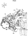
- the margin 61e of the first cable harness 61 may overlap the battery 50 disposed in front of the motor drive unit 30 in a side view of the vehicle body. This allows for a compact layout of the motor unit 40, the motor drive unit 30, and the battery 50, which are aligned in the longitudinal direction. Further, the position of the first cable harness 61 can be defined by utilizing the battery 50. For example, as shown in FIG. 9 , the margin 61e can be clamped to the cable mounting portion 51e formed on the side surface of the battery 50 with the use of a clamp member 71.
- the right side surface 36h of the motor drive unit 30 may be positioned closer to the center of the vehicle width direction than the right side surface 51a of the battery 50. That is, in a plan view of the vehicle body, the right side surface 36h of the motor drive unit 30 may be recessed from the right side surface 51a of the battery 50. This can provide a space behind the right portion of the battery 50.
- the first cable harness 61 may protrude to the right from the connector 37a provided on the right side surface 36h of the motor drive unit 30 (see FIG. 9 ). This arrangement of the motor drive unit 30 prevents the vehicle width from increasing due to the first cable harness 61 protruding from the right side surface 36h of the motor drive unit 30.
- the motor drive unit 30 may be offset leftward relative to the battery 50. That is, the center of the motor drive unit 30 in the left-right direction may be shifted to the left from the center of the battery 50 in the left-right direction. This allows for a space behind the right portion of the battery 50 for connecting the first cable harness 61 and the left side surface 0 of and the motor drive unit 30. In this space, the end of a second cable harness 62 to be described later on the motor drive unit 30 side may also be disposed.
- the motor unit 40 may have a portion 40a located to the right of the right side surface 36h of the motor drive unit 30.
- the portion 40a will be referred to as a rightmost portion.
- a portion of the electric motor 41 may be disposed on the rightmost portion 40a of the motor unit 40.
- the connector 61n of the first cable harness 61 may be connected to the rightmost portion 40a of the motor unit 40.
- the first cable harness 61 may extend forward from the rightmost portion 40a of the motor unit 40 in a plan view of the vehicle body.
- the first cable harness 61 extends forward from the motor unit 40 as described, which serves to prevent an increase in the vehicle width.
- the first cable harness 61 may extend obliquely upward and forward from the rightmost portion 40a of the motor unit 40, and may be curved over 180 degrees or more in the margin 61e.
- the end of the first cable harness 61 (connector 61m) may be connected to the connector 37a provided on the right side surface 36h of the motor drive unit 30.
- the position of the portion located forward than the front surface 36g of the motor drive unit 30 in the first cable harness 61 may be lower than the frame upper portion 21D.
- the position of the margin 61e (highest position in the margin 61e) may be lower than the upper end of the battery 50.
- the upper end of the battery 50 may be the upper end of the cable mounting portion 51h to which the second cable harness 62 to be described later is clamped.
- the position and connection of the first cable harness 61 are not limited to the example of the electric two-wheeled vehicle 1.
- the first cable harness 61 may extend obliquely upward and forward from the left portion of the motor unit 40.
- the first cable harness 61 may be connected to the left side surface 36i of the motor drive unit 30.
- the first cable harness 61 has a sufficient margin 61e, which serves to improve the workability of mounting the units 40 and 30 in a case where the units 30 and 40 are connected to each other by the first cable harness 61 for inspection of the units 30 and 40 and then the units 30 and 40 are sequentially mounted on the body frame 20.
- the inspection performed before mounting the units 30 and 40 is, for example, an inspection of the airtightness of the case 46 of the motor unit 40 and the case 36 of the motor drive unit 30.
- the motor unit 40 is connected to the motor drive unit 30 by the first cable harness 61.
- the case 46 of the motor unit 40 is connected to a breather hoses 47A and 47B (see FIG. 8 ) to allow air flow between the inside and the outside of the case 46.
- the breather hose 47A is connected to the right housing portion 46h containing the electric motor 41 in the case 46 and adjusts the atmospheric pressure therein.
- the breather hose 47B is connected to the left housing portion 46i containing the speed reduction mechanism 42 in the case 46 and adjusts the air pressure therein.
- air is pumped to the case 46 through the breather hoses 47A and 47B to inspect the airtightness of the case 46.
- the motor unit 40 and the motor drive unit 30 are connected to each other by the first cable harness 61, and thus the airtightness of the motor drive unit 30 can also be inspected.
- the electric two-wheeled vehicle 1 may have a second cable harness 62 for electrically connecting the drive circuit 31 and the battery 50.
- the power may be provided from the battery 50 to the drive circuit 31 through the second cable harness 62.
- the second cable harness 62 may include two power cables 62a.
- both the first cable harness 61 and the second cable harness 62 may be disposed in the same direction from the center of the vehicle body in the left-right direction.
- the connector 61m of the first cable harness 61 may be connected to the connector 37a provided on the right side surface 36h of the motor drive unit 30.
- the rear end of the second cable harness 62 is provided with the connector 62m connected to the connector 37b provided on the right side surface 36h of the motor drive unit 30.
- the right side surface 36h of the motor drive unit 30 is located closer to the center of the vehicle width direction from the right side surface 51a of the battery 50, and thus the space may be provided behind the right portion of the battery 50.
- the connector 61m of the first cable harness 61 and the connector 62m of the second cable harness 62 can be disposed using this space. This can prevent an increase in the vehicle width of the electric two-wheeled vehicle 1.
- the front end of the second cable harness 62 may be connected to the right side surface 51a of the battery 50. More specifically, the two power cables 62a of the second cable harness 62 may have connectors 62n at their front ends.
- the battery 50 may have two connectors on the right side of the lower portion of its foremost portion 50a.
- the connectors 62n of the second cable harness 62 may be respectively connected to the two connectors.
- the second cable harness 62 may be positioned to the right of the first cable harness 61. That is, the second cable harness 62 may be positioned outward in the vehicle width direction from the first cable harness 61.
- the second cable harness 62 may intersect the first cable harness 61 in a side view of the vehicle body and may be clamped to the battery 50 by a clamping member 72 (see FIG. 9 ). This prevents the first cable harness 61 from moving outward in the vehicle width direction.
- the component to which the second cable harness 62 is clamped may not be the battery 50.
- the second cable harness 62 may be clamped to the body frame 20.
- the first cable harness 61 may extend obliquely upward and forward from the connector 61n connected to the motor unit 40.
- the first cable harness 61 may be then curved downward.
- the connector 62m of the second cable harness 62 (the connector on the motor drive unit 30 side) may be positioned above the connector 61m of the first cable harness 61.
- the second cable harness 62 extends upward from the connector 62m and intersect the first cable harness 61.
- the outer surface of the second cable harness 62 is in contact with the outer surface of the first cable harness 61, although they may not necessarily be in contact with.
- the margin 61e of the first cable harness 61 may also be clamped to the battery 50 by the clamping member 71 (see FIG. 9 ).
- the position where the first cable harness 61 and the second cable harness 62 intersect is located rearward than the battery 50, and may be away from the position of the clamping member 71. That is, the second cable harness 62 may restrict the movement of the first cable harness 61 (movement to the right) at the position away from the clamp member 71.
- the second cable harness 62 may be disposed on the upper side of the battery 50, for example, may overlap the battery 50 in a plan view of the vehicle body. This arrangement of the second cable harness 62 prevents an increase in the vehicle width due to the second cable harness 62.
- the battery 50 may have a plurality of cable mounting portions 51h (see FIG. 3 ) protruding upward on its upper surface.
- the second cable harness 62 may extend forward on the upper side of the battery 50.
- the second cable harness 62 may be clamped to the cable mounting portion 51h by the clamp member 72.
- the cable mounting portion 51h may be positioned toward the center in the vehicle width direction than the right side surface 51a of the battery 50.
- the second cable harness 62 is also positioned toward the center in the vehicle width direction than the right side surface 51a.
- the first cable harness 61 intersecting the second cable harness 62 can be positioned toward the center in the vehicle width direction.
- the width of the foremost portion 50a of the battery 50 in the left-right direction may be smaller than the width at the rear portion than the foremost portion 50a.
- the battery 50 may have a connector on the right side of its foremost portion 50a.
- the second cable harness 62 may extend forward along the upper surface of the battery 50, and may be then curbed and extend downwardly along the right side of the foremost portion 50a of the battery 50.
- the connector 62n of the second cable harness 62 may be connected to a connector provided on the right side surface of the foremost portion 50a.
- Such a shape of the battery 50 and arrangement of the second cable harness 62 can prevent an increase in the vehicle width due to the second cable harness 62.
- the layout of the cable harnesses 61 and 62 is not limited to the example of the electric two-wheeled vehicle 1.
- the first cable harness 61 may be positioned outward of the second cable harness 62 in the vehicle width direction.
- the first cable harness 61 can prevent the second cable harness 62 from moving outward in the vehicle width direction.
- the cable harnesses 61 and 62 may be positioned to the left of the center in the vehicle width direction. In this case as well, the two cable harnesses 61 and 62 may intersect, and one cable harness may restrict the movement of the other cable harness (movement outward in the vehicle width direction).
- the first cable harness 61 may extend obliquely forward and downward from the motor unit 40.
- the first cable harness 61 may be curved upward thereafter and connected to the right side surface 36h of the motor drive unit 30.
- the second cable harness 62 may be disposed along the right side surface 51a of the battery 50 to restrict the movement of the first cable harness 61.
- the second cable harness 62 disposed along the right side surface 51a of the battery 50 may be clamped to the frame lower portion 21B of the body frame 20.
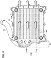
- the case 36 of the motor drive unit 30 may have a heat radiating portion on the rear surface. As shown in FIG. 10 , the case 36 may have a plurality of fins 36e as heat radiating portions.
- the case 36 may have a rear plate 36A that forms the rear surface. The fins 36e may be formed on the rear surface of the rear plate 36A.
- the case 36 may be box-shaped, and the drive circuit 31 (see FIG. 6 ) may be disposed inside the case 36.
- the drive circuit 31 may be attached to the rear plate 36A. The heat from the drive circuit 31 is transferred to the rear plate 36A, and can be released from the fins 36e.
- the case 36 may include a front case portion 36B that covers the front side of the drive circuit 31 and is combined with the rear plate 36A in the longitudinal direction.
- the rear plate 36A and the front case portion 36B may be formed of metal.
- the size of the battery 50 may be larger than the motor drive unit 30 in the vertical and left-right directions.
- the motor drive unit 30 may be disposed so as to overlap the battery 50. As such, when the electric two-wheeled vehicle 1 travels, at least a part of the air flow to the motor drive unit 30 is blocked by the battery 50.
- the electric two-wheeled vehicle 1 may include an air guide 77.
- the air guide 77 may include a cover portion 77A that covers the rear surface of the case 36.
- the cover portion 77A may cover the entire fins 36e formed on the rear surface of the case 36.
- Air flow path may be formed between the rear surface of the case 36 and the cover portion 77A.
- Each fin 36e extends in the left-right direction, and the fins 36e may be arranged in the vertical direction.
- the air flow path extending in the left-right direction may be provided between the cover portion 77A and the rear surface of and the case 36.
- the air guide 77 may be attached to the motor drive unit 30. This structure serves to appropriately set the distance between the motor drive unit 30 and the air guide 77. In the example of the electric two-wheeled vehicle 1, the air guide 77 may be attached to the mounting portions 36j formed on the rear surface of the rear plate 36A.
- a plurality of mounting portions 77e and 77f may be formed on the upper edge of the air guide 77.
- the above-described front end of the breather hoses 47A and 47B connected to the motor unit 40 may be held by the mounting portions 77e and 77f, for example.
- the edges of the breather hoses 47A and 47B may be held by the body frame 20 (e.g., brackets 21g, 21h).
- the air guide 77 may have a projecting portion 77B extending leftward from the cover portion 77A.
- the projecting portion 77B may extend to the left beyond the left side surface 36i of the motor drive unit 30. This structure can use the projecting portion 77B to deliver air to the rear surface of the case 36 so as to cool the drive circuit 31.
- the direction in which the projecting portion 77B extends may not necessarily be left and may be any direction if the direction intersects the direction in which the battery 50 and the motor drive unit 30 are aligned (longitudinal direction in the example of the electric two-wheeled vehicle 1).
- the projecting portion 77B may extend from the cover portion 77A to the right, and exceed the position of the right side surface 36h of the motor drive unit 30.
- the projecting portion 77B may extend downward from the cover portion 77A, and exceed the position of the lower surface of the motor drive unit 30.
- the projecting portion 77B may extend obliquely left, right, or downward.
- an air duct 78 may be connected to the projecting portion 77B.
- the air duct 78 may extend forward from the projecting portion 77B.
- the front end of the air duct 78 may open forward, for example.
- the air duct 78 may be disposed above the battery 50. This prevents an increase in the vehicle width due to the air duct 78.
- the electric two-wheeled vehicle 1 may have a body cover 14 (see FIG. 1 ) covering the upper, right, and left sides of the battery 50.
- the air duct 78 may be disposed between the body cover 14 and the battery 50.
- the front end of the air duct 78 may be located, for example, behind the front wheel 2.
- the electric two-wheeled vehicle 1 may have a battery guard 15 located behind the front wheel 2 and in front of the battery 50.
- An opening 15a may be formed in the battery guard 15.
- the front end of the air duct 78 may be connected to the opening 15a.
- the opening 15a may be located between the left and right cushions 8 that support the front wheel 2.
- the position of the front end (opening) of the air duct 78 is not limited to the example of the electric two-wheeled vehicle 1.
- an opening may be formed in the vehicle cover 14 covering the right side and the left side of the battery 50, and the front end of the air duct 78 may be connected to the opening.
- the position of the motor drive unit 30 may be shifted to the left from the battery 50. That is, the center of the motor drive unit 30 in the left-right direction may be shifted to the left from the center of the battery 50 in the left-right direction. As such, it is easy to feed the rear surface of the case 36 by utilizing the projecting portion 77B.
- the left side surface 36i of the motor drive unit 30 may be positioned to the left than the left side surface 51b of the battery 50.
- the projecting portion 77B may extend leftward beyond the position of the left side surface 51b of the battery 50.
- an exhaust port E may be formed on the opposite side of the projecting portion 77B across the cover portion 77A covering the fins 36e.
- the exhaust port E may be open to the right. The air passing between the cover portion 77A and the rear surface of the case 36 (i.e., between the cover portion 77A and the fins 36e) can be discharged from the exhaust port E.
- the positions of the exhaust port E and the projecting portion 77B are not limited to the example of the electric two-wheeled vehicle 1.
- the projecting portion 77B may extend downward from the cover portion.
- the exhaust port E may open upward, and each fin 36e may extend in the vertical direction. Further, the exhaust port E may open in two orthogonal directions. For example, the exhaust port E may open downward and rightward.
- the heat radiating portion of the case 36 may be a plurality of columnar projections instead of the fins 36e.
- the width of the projecting portion 77B (width in the left-right direction) may be smaller as it is further away from the connection position of the duct 78 upward or downward.
- a reference symbol W1 is attached to the maximum width of the projecting portion 77B.
- the width of the upper portion 77a of the projecting portion 77B may be smaller as the width approaches upward or downward.
- the width of the lower portion 77b of the projecting portion 77B may be smaller than that of the upper portion 77a, and may be constant in the vertical direction.
- the air duct 78 may be located above the battery 50. As such, air introduced at the front end of the air duct 78 can flow obliquely rearward and downward. If the width of the projecting portion 77B is even from the upper end to the lower end of the cover portion 77A, air flows intensively to the lower fins 36e. In contrast, in the example of the electric two-wheeled vehicle 1, the width of the projecting portion 77B is smaller in the lower portion 77b of the cover portion 77A, and thus it is possible to prevent the air from concentrating on the lower fins 36e. In other words, the air can be sent to the entire fins 36e.
- the electric two-wheeled vehicle 1 may not have the air duct 78.
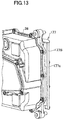
- FIGs. 12 and 13 are diagrams illustrating examples of a structure in which the air duct 78 is not provided.
- an air guide 177 may be attached to the motor drive unit 30.
- the air guide 177 may include a projecting portion 177B extending leftward from the cover portion 177A.
- the projecting portion 177B may have a front surface 177c exposed forward.
- the edge of the projecting portion 177B may be curved forward.
- the projecting portion 177B may extend to the left beyond the left side surface 36i of the motor drive unit 30.
- the air guide 77 may include a right cover portion 77A and a left cover portion 77A with the exhaust port E therebetween.
- the air guide 77 may have the projecting portion 77B extending to the right from the cover portion 77A on the right, and the projecting portion 77B extending to the left from the cover portion 77A on the left.
- the structure of the electric two-wheeled vehicle proposed in the present disclosure is not limited to the example of the electric two-wheeled vehicle 1, and various modifications may be made.
- the first cable harness 61 has the margin 61e, and the motor drive unit 30 is disposed between the battery 50 and the motor unit 40.
- the structure of the electric two-wheeled vehicle in which the motor unit 40 is provided with two mounting portions 46a and 46b may be applied to an electric two-wheeled vehicle having a different layout.
- the electric two-wheeled vehicle 1 may not have the air guide 77. In this case, each fin 36e formed on the rear surface of the motor drive unit 30 may extend in the vertical direction.
Landscapes
- Engineering & Computer Science (AREA)
- Mechanical Engineering (AREA)
- Chemical & Material Sciences (AREA)
- Combustion & Propulsion (AREA)
- Transportation (AREA)
- Axle Suspensions And Sidecars For Cycles (AREA)
- Automatic Cycles, And Cycles In General (AREA)
- Electric Propulsion And Braking For Vehicles (AREA)
Abstract
Description
- The present invention relates to a straddled electric vehicle.
- An electric two-wheeled vehicle includes an electric motor and a battery that stores power to be supplied to the electric motor. In the electric two-wheeled vehicle disclosed in
JP 2005-201357 A JP 2005-201357 A - In many electric two-wheeled vehicles, the space formed between the electric motor and the seat is effectively utilized. For example, in the electric two-wheeled vehicle of
JP 2005-201357 A - It is the object of the present invention to provide a straddled electric vehicle in that capacity of the battery and/or capacity of a storage case can be increased. According to the present invention said object is solved by a straddled electric vehicle having the features of
independent claim 1. Preferred embodiments are laid down in the dependent claims. - (1) An example of a straddled electric vehicle proposed in the present disclosure includes a seat, a battery, a motor unit including an electric motor driven by power of the battery, the motor unit being disposed below the seat and behind the battery, and a body frame supporting the motor unit. The motor unit includes an upper mounting portion and a lower mounting portion that are attached to the body frame, and does not include a portion that is attached to the body frame rearward than the upper mounting portion and the lower mounting portion. The upper mounting portion is located forward than a rotation center of the electric motor. This structure can lower a position of the upper mounting portion as compared with a structure in which the upper mounting portion is located upward from the rotation center of the electric motor. As a result, the space between the seat and the motor unit can be increased.
- (2) In the straddled electric vehicle of (1), the motor unit may include the electric motor, a first rotation shaft at the rotation center of the electric motor, a second rotation shaft away from the first rotation shaft, and a speed reduction mechanism supported by the first rotation shaft and the second rotation shaft. The second rotation shaft may be located below the first rotation shaft, and the lower mounting portion may be located forward than a rotation center of the second rotation shaft. This structure enables the lower mounting portion to be positioned higher as compared with a structure in which the lower mounting portion is positioned below the second rotation shaft. As a result, while ensuring the minimum ground height of the vehicle body, the position of the motor unit can be lowered.
- (3) The straddled electric vehicle of (1) may further include a motor drive unit including a drive circuit that supplies power of the battery to the electric motor. The motor drive unit may be disposed behind the battery and in front of the motor unit, and the lower mounting portion may be located below a lower end of the motor drive unit. This structure allows the motor unit to be positioned closer to the motor drive unit that is located in front of the motor unit.
- (4) In the straddled electric vehicle of (3), a lower surface of the motor drive unit may be located above a lower surface of the battery, and a position of the lower mounting portion may be a same height as the lower surface of the battery or higher than the lower surface of the battery. This structure can easily assure the minimum ground height of the vehicle body.
- (5) In the straddled electric vehicle of (1), a position of the upper mounting portion may be lower than an upper end of the motor drive unit. This structure can increase space formed above the motor unit.
- (6) The straddled electric vehicle of (1) further includes a motor drive unit including a drive circuit that supplies power of the battery to the electric motor. The motor drive unit may be disposed behind the battery and in front of the motor unit, and the body frame may include a support structure below the motor drive unit, the support structure being mounted on the lower mounting portion to support the motor unit. This structure can effectively utilize space formed below the motor drive unit to support the motor unit.
- (7) In the straddled electric vehicle of (1), the motor unit may include the electric motor, a first rotation shaft at the rotation center of the electric motor, a second rotation shaft away from the first rotation shaft, and a speed reduction mechanism supported by the first rotation shaft and the second rotation shaft, and the second rotation shaft may be located below the first rotation shaft and forward than the first rotation shaft. This structure can increase a distance from the second rotation shaft to the axle of the rear wheel (in other words, the length of the rear arm) without increasing the wheel base.
- (8) In the straddled electric vehicle of (7), the lower mounting portion may be located forward than the rotation center of the second rotation shaft. This structure enables the lower mounting portion to be positioned higher as compared with a structure in which the lower mounting portion is positioned below the second rotation shaft. As a result, while ensuring the minimum ground height of the vehicle body, the position of the motor unit can be lowered.
- (9) The straddled electric vehicle of (8) further includes a motor drive unit including a drive circuit that supplies power of the battery to the electric motor. The position of the second rotation shaft may be lower than the lower end of the motor drive unit. This structure can easily prevent interference between the motor unit and the motor drive unit.
- (10) In the straddled electric vehicle of (1), a storage case may be disposed above the motor unit and below the seat. With this structure, a case having a large capacity can be used as the storage case.
- (11) The straddled electric vehicle of (1) may further include a rear wheel disposed behind the motor unit, a rear arm supporting the rear wheel, and a rear cushion coupled to the rear arm and the body frame. The upper end of the rear cushion may be located forward than the rear wheel and rearward than the upper mounting portion of the motor unit. This structure can reduce the vibration acting on the rear portion of the body frame through the rear cushion when the electric two-wheeled vehicle travels.
-
-
FIG. 1 is a side view illustrating an example of a straddled electric vehicle proposed in the present disclosure; -
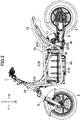
FIG. 2 is a side view of an entire vehicle body without a vehicle cover; -
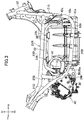
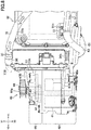
FIG. 3 is a right side view of a battery, a motor drive unit, and a motor unit that are mounted on a body frame; -
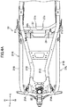
FIG. 4A is a plan view of the body frame; -
FIG. 4B is a rear view of the body frame; -
FIG. 5 is a perspective view of the battery, the motor drive unit, and the motor unit; -
FIG. 6 is a left side view of the battery, the motor drive unit, and the motor unit. InFIG. 6 , an air guide shown inFIG. 5 covering the back of the motor drive unit is omitted; -
FIG. 7 is a right side view of the battery, the motor drive unit, and the motor unit; -
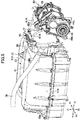
FIG. 8 is a plan view of the motor drive unit and the motor unit; -
FIG. 9 is a perspective view illustrating the right side of the motor drive unit and the motor unit; -
FIG. 10 is an exploded perspective view of the motor drive unit and the air guide; -
FIG. 11 is a rear view of the motor drive unit and the air guide; -
FIG. 12 is a perspective view illustrating a variation of the air guide; and -
FIG. 13 is a perspective view of the air guide according to the variation inFIG. 12 viewed from the diagonally rear side. - In the following, a straddled electric vehicle proposed in this embodiment will be described. In this specification, as an example of a straddled electric vehicle, an electric two-
wheeled vehicle 1 shown in drawings such asFIG. 1 will be described. The straddled electric vehicle may be a four-wheeled or three-wheeled electric vehicle having a seat on which a rider straddles and sits. - The terminology used herein is for the purpose of describing particular embodiments. As used herein, the term "and/or" includes any and all combinations of one or more of the associated listed items. As used herein, the singular forms "a," "an," and "the" are intended to include the plural forms as well as the singular forms, unless the context clearly indicates otherwise. It will be further understood that the terms "comprises", "comprising", "includes", and/or "including", when used in this specification, specify the presence of stated features, steps, operations, elements, and/or components, but do not preclude the presence or addition of one or more other features, steps, operations, elements, components, and/or groups thereof.
- Unless otherwise defined, all terms (including technical and scientific terms) used herein have the same meaning as commonly understood by one having ordinary skill in the art to which the present teaching belongs. It will be further understood that terms, such as those defined in commonly used dictionaries, should be interpreted as having a meaning that is consistent with their meaning in the context of the relevant art and the present disclosure and will not be interpreted in an idealized or overly formal sense unless expressly so defined herein.
- In describing the present teaching, it will be understood that a number of technologies are disclosed. Each of these has individual benefit and each can also be used in conjunction with one or more, or in some cases all, of the other disclosed technologies. Accordingly, for the sake of clarity, this description will refrain from repeating every possible combination of the individual technologies in an unnecessary fashion.
- In the following description, for purposes of explanation, numerous specific details are set forth in order to provide a thorough understanding of the present teaching.
- The present disclosure is to be considered as an exemplification of the present teaching.
- In the drawings such as
FIG. 1 , directions indicated by X1 and X2 are referred to as a right direction and a left direction, respectively, and directions indicated by Z1 and Z2 are referred to as an upward direction and a downward direction, respectively. The directions Y1 and Y2 shown inFIG. 2 are referred to as a forward direction and a rearward direction, respectively. Further, the direction indicated by X1-X2 is referred to as a vehicle width direction or a vehicle left-right direction. The direction indicated by Y1-Y2 is referred to as a vehicle longitudinal direction or a vehicle front-rear direction. The direction indicated by Z1-Z2 is referred to as a vehicle vertical direction or a vehicle up-down direction. - As shown in
FIG. 2 , the electric two-wheeled vehicle 1 has afront wheel 2, arear wheel 3, asteering handle 5 for steering thefront wheel 2, and a seat 6 (seeFIG. 1 ) disposed behind thesteering handle 5. The electric two-wheeled vehicle 1 has arear arm 9 connected to abody frame 20 via apivot 29. The rear portion of therear arm 9 is connected to the axle of therear wheel 3. The electric two-wheeled vehicle 1 has arear cushion 11 connected to therear arm 9 and thebody frame 20. The lower end of therear cushion 11 is connected to therear arm 9, and the upper end of therear arm 9 is connected to the body frame 20 (more specifically, a framerear portion 21C to be described later). - As shown in
FIG. 2 , thebody frame 20 has, at its foremost portion, ahead pipe 22 supporting a steering shaft to which the steering handle 5 is connected. The left and right front cushions 8 are connected to the lower portion of the steering shaft, and thefront wheel 2 is supported by the lower end of the front cushions 8. - The
body frame 20 has aright portion 21R (seeFIG. 4A ) and aleft portion 21L (seeFIG. 4A ). As shown inFIG. 2 , each of theright portion 21R and theleft portion 21L includes aframe front portion 21A extending downward from thehead pipe 22, a framelower portion 21B extending rearward from theframe front portion 21A and disposed in the lower body, and a framerear portion 21C extending obliquely rearward and upward from the framelower portion 21B. The threeportions right portion 21R and theleft portion 21L of thebody frame 20 has a frameupper portion 21D. The frameupper portion 21D extends rearward from the middle of theframe front portion 21A, and is away upward from the framelower portion 21B in a side view of the vehicle body. The upper portion of the framerear portion 21C is connected to the rear portion of the frameupper portion 21D. Theseat 6 is supported on the upper side of the rear portion of the frameupper portion 21D. - As shown in
FIG. 5 , the electric two-wheeled vehicle 1 includes abattery 50, amotor unit 40, and amotor drive unit 30. - The
battery 50 includes a plurality of battery cells and a controller for controlling the charging and discharging of thebattery 50. Thebattery 50 has abattery housing 51 containing the battery cells and the controller. Thebattery 50 is, for example, a lithium ion battery. - The
motor unit 40 includes an electric motor 41 (seeFIG. 8 ) and acase 46 containing theelectric motor 41. Theelectric motor 41 is a driving source of the electric two-wheeled vehicle 1, and its rotation is transmitted to therear wheel 3. In the example of the electric two-wheeled vehicle 1, themotor unit 40 has a speed reduction mechanism 42 (seeFIG. 8 ). Thespeed reduction mechanism 42 is also housed in thecase 46. - As shown in
FIG. 8 , thecase 46 has, for example, aright housing portion 46h containing theelectric motor 41 and aleft housing portion 46i containing thespeed reduction mechanism 42. The inside of theright housing portion 46h and the inside of theleft housing portion 46i may be partitioned. - As shown in
FIG. 6 , themotor unit 40 includes a first rotation shaft 43 (seeFIG. 8 ) at the rotation center Cm of theelectric motor 41, and a second rotation shaft 44 (seeFIG. 8 ) radially away from thefirst rotation shaft 43 of theelectric motor 41. Thespeed reduction mechanism 42 is supported by therotation shafts electric motor 41 is input to thefirst rotation shaft 43. Thespeed reduction mechanism 42 reduces the rotation of thefirst rotation shaft 43 and transmits the rotation to thesecond rotation shaft 44. - The
speed reduction mechanism 42 is a gear type, for example, and is composed of a gear supported by thefirst rotation shaft 43 and a gear supported by thesecond rotation shaft 44. Thespeed reduction mechanism 42 may be a belt type, for example. Thespeed reduction mechanism 42 may be a transmission capable of changing the reduction ratio. - The
second rotation shaft 44 is, for example, an output shaft of themotor unit 40, and is connected to therear wheel 3 via a rotation transmission component such as a belt, a chain, and a shaft. In the example of the electric two-wheeled vehicle 1, the rotation transmission component is a belt 12 (seeFIG. 2 ), and apulley 44a (seeFIG. 5 ) for catching the foremost portion of the belt 12 is attached to the end of thesecond rotation shaft 44. The pivot 29 (seeFIG. 2 ) supporting therear arm 9 and thesecond rotation shaft 44 are aligned on the same axis. - The
first rotation shaft 43 is coaxial with the rotation center Cm of theelectric motor 41. Thesecond rotation shaft 44 is positioned below thefirst rotation shaft 43. Further, thesecond rotation shaft 44 is positioned forward than thefirst rotation shaft 43. With this layout of thesecond rotation shaft 44, the distance from thesecond rotation shaft 44 to the axle of the rear wheel 3 (in other words, the length of the rear arm 9) can be increased without increasing the wheel base. - Unlike the example of the electric two-
wheeled vehicle 1, thesecond rotation shaft 44 may be positioned directly below thefirst rotation shaft 43 or may be positioned rearward than thefirst rotation shaft 43. In yet another example, themotor unit 40 may not have thesecond rotation shaft 44. - The
motor drive unit 30 includes a drive circuit 31 (seeFIG. 6 ) and acase 36 containing thedrive circuit 31. Thedrive circuit 31 uses the power of thebattery 50 to supply electric power corresponding to the rider's accelerator operation (operation of the accelerator grip provided in the steering handle 5) to theelectric motor 41. Theelectric motor 41 is an AC motor (e.g., three-phase AC motor). Thedrive circuit 31 includes an inverter, which converts the DC power output by thebattery 50 to AC power of a frequency corresponding to the vehicle speed. The inverter is composed of a semiconductor switching device, such as FET (Field Effect Transistor). - The electric two-
wheeled vehicle 1 may have a vehicle control unit (not shown) having a microprocessor or a memory. The vehicle control unit calculates a command value (current command value) based on the accelerator operation, and outputs a signal corresponding to the command value. Thedrive circuit 31 supplies power corresponding to the command value to theelectric motor 41. The arrangement of the vehicle control unit is not particularly limited. - As shown in
FIG. 2 , thebattery 50 is disposed at the center of the vehicle body. At least the front portion of thebattery 50 is located forward than the seat 6 (seeFIG. 1 ). In one example, theentire battery 50 is located forward than theseat 6. Alternatively, only the front portion of thebattery 50 may be located forward than theseat 6, and the rear portion of thebattery 50 may be located rearward than theseat 6. The height of thebattery 50 is lower than the front end of theseat 6. - The
motor unit 40 is located behind thebattery 50 and below theseat 6. Themotor drive unit 30 is positioned between thebattery 50 and themotor unit 40. That is, themotor drive unit 30 is disposed rearward of thebattery 50, and themotor unit 40 is disposed further rearward of themotor drive unit 30. In the example of the electric two-wheeled vehicle 1, themotor drive unit 30 is disposed such that the front and rear surfaces of themotor drive unit 30 are substantially perpendicular to the longitudinal direction of the vehicle body. Similarly, thebattery 50 is disposed such that the rear surface of thebattery 50 is also substantially perpendicular to the longitudinal direction of the vehicle body. Thebattery 50, themotor drive unit 30, and themotor unit 40 are positioned between theright portion 21R and theleft portion 21L of thebody frame 20 in a plan view of the vehicle body. Thebattery 50, themotor drive unit 30, and themotor unit 40 may be partially located outside theright portion 21R and theleft portion 21L of thebody frame 20. - The
motor unit 40 is supported by thebody frame 20. As shown inFIG. 5 , the motor unit 40 (more specifically, the case 46) may have an upper mountingportion 46a and alower mounting portion 46b, which are attached to thebody frame 20. The number of mounting portions of themotor unit 40 may be two, for example. As such, themotor unit 40 may not need to have a portion to be attached to thebody frame 20 in an area located rearward than the two mountingportions motor unit 40. - In the example of the electric two-
wheeled vehicle 1, a storage case 13 (seeFIG. 2 ) for housing the equipment such as a helmet may be disposed below theseat 6 and above themotor unit 40. Themotor unit 40 does not have a portion to be attached to thebody frame 20 in an area located rearward than the mountingportions storage case 13 can be increased at the rear side of the upper mountingportion 46a. - The component that utilizes the space between the
motor unit 40 and theseat 6 may not be thestorage case 13. For example, a spare battery may be disposed between themotor unit 40 and theseat 6. In this case, the capacity of the spare battery can be increased. - The upper surface of the
case 46 may be curved to match the outer shape of theelectric motor 41 in a side view of the vehicle body. Thecase 46 may have a convex portion protruding upward from its upper surface. The upper mountingportion 46a may be formed at an end portion of the convex portion. In the example of the electric two-wheeled vehicle 1, the upper mountingportion 46a may be a portion where a through-hole, into which a coupling shaft S1 (seeFIG. 6 ) described later is inserted, is formed. - As shown in
FIG. 6 , the upper mountingportion 46a may be positioned forward than the rotation center Cm of theelectric motor 41. That is, the upper mountingportion 46a may be forward from the vertical plane passing through the rotation center Cm. According to this structure, the position of the upper mountingportion 46a can be lowered as compared with the structure in which the upper mountingportion 46a is located directly above the rotation center Cm. As a result, the space between theseat 6 and the motor unit 40 (in the example of the electric two-wheeled vehicle 1, the space for the storage case 13) can be increased. - As shown in
FIG. 6 , the position of the upper mountingportion 46a may be lower than theupper end 36c of themotor drive unit 30. This structure can increase the capacity of thestorage case 13 disposed in the space formed above themotor unit 40. - According to the above-described structure of mounting the
motor unit 40, the space is provided behind themotor unit 40, and thus it is also possible to move the position of therear cushion 11 forward. In the example of the electric two-wheeled vehicle 1, the upper end of therear cushion 11 may be coupled to thebody frame 20 at a position located forward than therear wheels 3 and located rearward than the upper mountingportion 46a of themotor unit 40. As a result, when the electric two-wheeled vehicle 1 travels, the vibration acting on the rear portion of the frameupper portion 21D, which supports theseat 6, through therear cushion 11 can be reduced. In the example of the electric two-wheeled vehicle 1, the upper end of therear cushion 11 may be positioned above themotor unit 40 in a side view of the vehicle body. On the other hand, the lower end of therear cushion 11 may be coupled to therear arm 9 at a position forward than therear wheel 3 and rearward than themotor unit 40. The position of therear cushion 11 is not limited to the example shown inFIG. 2 . - As shown in
FIG. 4B , thebody frame 20 may havecross portions right portion 21R and theleft portion 21L of thebody frame 20. Thecross portions upper cross portion 27 may be stretched between the middle portions of the left and right framerear portions 21C, for example. Thelower cross portion 28 may be stretched between the lower portions of the left and right framerear portions 21C (rear portions of the left and right framelower portions 21B), for example. Themotor unit 40 may be supported by thecross portions - The left and
right brackets 27a (seeFIG. 4B ) may be attached to theupper cross portion 27. The left andright brackets 27a may support the coupling shaft S1. The upper mountingportion 46a is cylindrical, and the coupling shaft S1 may be passed through the upper mountingportion 46a. In this manner, the upper mountingportion 46a is supported by thecross portion 27 via the coupling shaft S1 and thebrackets 27a. - As shown in
FIG. 6 , thebody frame 20 may havebrackets 28a extending rearward obliquely and downwardly from the lower portion of the left and right framerear portions 21C (in other words, the rear portion of the left and right framelower portions 21B). The lower cross section 28 (seeFIG. 3B ) may be supported by left andright brackets 28a. The left andright brackets 28b (seeFIG. 4B ) extending rearward may be attached to thelower cross portion 28. The left andright brackets 28b may support the coupling shaft S2. Thecase 46 of themotor unit 40 may have a convex portion projecting obliquely forward and downward from the lower portion of itsfront surface 46c. Thelower mounting portion 46b may be formed at the end portion of the convex portion. Thelower mounting portion 46b has a through hole formed therein, and the coupling shaft S2 may be provided through the lower mountingportion 46b. In this manner, the lower mountingportion 46b can be supported by thecross portion 28 via thebrackets 28b and the coupling shaft S2. - The lower portion of the frame
rear portion 21C may be fixed tobrackets 25 for supporting the pivot 29 (seeFIG. 2 ) of therear arm 9. Thebrackets 25 may extend rearwardly from the lower portion of the framerear portion 21C. In a side view of the vehicle body, theupper cross section 27 may be positioned above thebrackets 25. Thelower cross section 28 may be located below and forward of thebrackets 25. The stiffness of the portion of thebody frame 20 where thebrackets 25 are provided can be increased by thecross sections - The lower portion of the
case 46 of themotor unit 40 may be curved to match the outer shape of the gear disposed on thesecond rotation shaft 44. Thelower mounting portion 46b may be positioned forward than the rotation center of thesecond rotation shaft 44. This structure enables the lower mountingportion 46b to be positioned higher as compared with the structure in which the lower mountingportion 46b is positioned below thesecond rotation shaft 44. As a result, while ensuring the minimum ground height of the vehicle body, the position of themotor unit 40 can be lowered, and the capacity of thestorage case 13 can be thereby increased. - As described above, the lower mounting
portion 46b may be formed at the end of the convex portion projecting obliquely forward and downward from thefront surface 46c of thecase 46. Accordingly, the position of the lower mountingportion 46b may be forward than thefront surface 46c of thecase 46 of themotor unit 40. Further, the entire convex portion at which the lower mountingportion 46b is formed may be positioned forward than the rotation center of thesecond rotation shaft 44. Alternatively, the bottom of the convex portion may be positioned below the rotation center of thesecond rotation shaft 44, and the front end of the convex portion (i.e., the lower mountingportion 46b) may be positioned forward than the vertical plane passing through the rotation center of thesecond rotation shaft 44. - The
lower mounting portion 46b may be positioned below the rotation center of thesecond rotation shaft 44. That is, the lower mountingportion 46b may be positioned below the horizontal plane passing through the rotation center of thesecond rotation shaft 44. With this structure, the distance between the upper mountingportion 46a and the lower mountingportion 46b can be increased in the vertical direction, and the support strength of the motor unit can be thereby increased. - The position of the lower mounting
portion 46b may be higher than thelower end 46d of the motor unit 40 (the lower end of the case 46). This prevents the lower mountingportion 46b from affecting the minimum ground height of the electric two-wheeled vehicle 1. - The
motor unit 40 may not necessarily have thesecond rotation shaft 44. In this case as well, the upper mountingportion 46a and the lower mountingportion 46b may be preferably located forward than the rotation center Cm of theelectric motor 41. This structure can reduce the size in the vertical direction of themotor unit 40 as compared with the case where the upper mountingportion 46a and the lower mountingportion 46b are respectively disposed directly above and below the rotation center Cm of theelectric motor 41. - The
motor drive unit 30 may be disposed in front of themotor unit 40. As shown inFIG. 6 , the lower mountingportion 46b may be positioned below thelower end 36d of themotor drive unit 30. This structure allows themotor unit 40 to be positioned closer to themotor drive unit 30 while avoiding interference between the lower mountingportion 46b and themotor drive unit 30. As a result, the size of the vehicle body in the longitudinal direction can be reduced. In the example of the electric two-wheeled vehicle 1, the position of thesecond rotation shaft 44 is also lower than thelower end 36d of themotor drive unit 30. - The front end of the lower mounting
portion 46b may be positioned forward than the rear end of themotor drive unit 30. With this structure, themotor unit 40 and themotor drive unit 30 can be efficiently disposed in a small space. In the example of the electric two-wheeled vehicle 1, as shown inFIG. 6 , the front end of the lower mountingportion 46b may be positioned forward than the rear end of afin 36e formed on the rear surface of themotor drive unit 30. Unlike the example of the electric two-wheeled vehicle 1, the position of the lower mountingportion 46b may be rearward from the rear end (fin 36e) of themotor drive unit 30. - As described above, the lower mounting
portion 46b may be supported by thebody frame 20. The support structure of the lower mountingportion 46b may be located below themotor drive unit 30. In the example of the electric two-wheeled vehicle 1, as shown inFIG. 6 , thelower cross portion 28 and thebrackets 28b extending rearward from thelower cross portion 28 may be positioned below themotor drive unit 30. This enables to effectively use the space below themotor drive unit 30. - As shown in
FIG. 6 , themotor drive unit 30 may offset upward relative to thebattery 50. That is, the center of themotor drive unit 30 in the vertical direction may be positioned above the center of thebattery 50 in the vertical direction. The height of thelower surface 36f of themotor drive unit 30 may be thus above the lower surface of thebattery 50. Further, a space may be formed rearward of the lower portion of thebattery 50 and below themotor drive unit 30, and thelower cross portion 28 and thebrackets 28b may be disposed in this space. - The relationship between the position of the
motor drive unit 30 and the position of thebattery 50 is not limited to the example of the electric two-wheeled vehicle 1. For example, the position of themotor drive unit 30 may not be offset upward relative to the position of thebattery 50. In this case as well, if the size in the vertical direction of themotor drive unit 30 is smaller than the size in the vertical direction of thebattery 50, the position of thelower surface 36f of themotor drive unit 30 is higher than the lower surface of thebattery 50. As a result, the space formed behind the lower portion of thebattery 50 can be effectively utilized. - As shown in
FIG. 2 , a reinforcingportion 21E extending in the vertical direction may be disposed between the frameupper portion 21D and the framerear portion 21C. As shown inFIG. 4B ,brackets portion 21E. The upper portion of the motor drive unit 30 (upper portion of the case 36) may be attached to thebrackets FIG. 4B , thebrackets 28d may be also formed in thelower cross portion 28. The lower portion of themotor drive unit 30 may be attached to thebrackets 28d in the longitudinal direction. - As shown in
FIG. 7 , the electric two-wheeled vehicle 1 has afirst cable harness 61 for electrically connecting theelectric motor 41 and thedrive circuit 31. The power for driving theelectric motor 41 is supplied from thedrive circuit 31 to theelectric motor 41 through thefirst cable harness 61. Thefirst cable harness 61 may have a plurality ofpower cables 61a. Theelectric motor 41 may be a three-phase AC motor, for example, and thefirst cable harness 61 may include threepower cables 61a, for example. - The
motor unit 40 may be located behind themotor drive unit 30. The length of thefirst cable harness 61 connecting theelectric motor 41 and thedrive circuit 31 may have a margin than the shortest length connecting them. As such, as shown inFIG. 7 , thefirst cable harness 61 may have, in the middle thereof, aportion 61e located forward than thefront surface 36g of themotor drive unit 30. Hereinafter, theportion 61e is referred to as a "margin". - In the assembly process of the electric two-
wheeled vehicle 1, in a state where themotor drive unit 30 and themotor unit 40 are connected by thefirst cable harness 61, the work of mounting themotor drive unit 30 on thebody frame 20 and the work of mounting themotor unit 40 on thebody frame 20 may be sequentially performed. For example, before being mounted on thebody frame 20, sometimes theunits first cable harness 61 for inspection. In that case, the subsequent mounting operation of theunits units first cable harness 61. This mounting operation is restricted by the length of thefirst cable harness 61. In the example of the electric two-wheeled vehicle 1, thefirst cable harness 61 includes themargin 61e located forward than thefront surface 36g of themotor drive unit 30, and thus the length of thefirst cable harness 61 has a sufficient margin, and the workability of mounting theunits - As shown in
FIG. 9 , one end of thefirst cable harness 61 may be connected to the side surface of themotor drive unit 30. Aconnector 61m may be provided at the end of thefirst cable harness 61. Theconnector 61m may be connected to aconnector 37a provided on the side surface of themotor drive unit 30. The other end of thefirst cable harness 61 may be connected to themotor unit 40. As described above, thefirst cable harness 61 may have the threepower cables 61a. Aconnector 61n may be provided at each of the ends of thepower cables 61a. Theconnectors 61n may be respectively connected to the three connectors provided in themotor unit 40. - As shown in
FIG. 7 , thefirst cable harness 61 may have aforemost portion 61f in themargin 61e. Theforemost portion 61f may be a portion positioned most forwardly in thefirst cable harness 61. The distance between a vertical plane V3 passing through theforemost portion 61f and a vertical plane V4 passing through theconnector 61m (the end on themotor drive unit 30 side) may be longer than the distance between the vertical plane V4 passing through theconnector 61m and a vertical plane V5 passing through theconnector 61n (the end on themotor unit 40 side). Here, the vertical plane V4 is a vertical plane passing through the center of theconnector 61m in a side view of the vehicle body. The vertical plane V5 is a vertical plane passing through themiddle connector 61n of the threeconnectors 61n. - The
margin 61e of thefirst cable harness 61 may be curved over 180 degrees or more in a side view of the vehicle body. In the example of the electric two-wheeled vehicle 1, as shown inFIG. 7 , themargin 61e may be curved along an arc A defined around its inner center Cf. The angle θ of the arc A may be 180 degrees or more. In the example of the electric two-wheeled vehicle 1, the entire curved portion along the arc A may be positioned forward than thefront surface 36g of themotor drive unit 30. Unlike the example of the electric two-wheeled vehicle 1, only a portion of the curved portion along the arc A may be positioned forward than thefront surface 36g of themotor drive unit 30. Due to the curved portion, the extending direction of thefirst cable harness 61 is reversed in the middle of thefirst cable harness 61. - The radius of curvature R of the arc A along the
margin 61e may be greater than three times a diameter of eachpower cable 61a. This prevents a large load on thepower cables 61a. The radius of curvature R may be greater than four times a diameter of eachpower cable 61a. - As shown in
FIG. 9 , in the vicinity of theconnector 61m on themotor drive unit 30 side, thefirst cable harness 61 may have acurved portion 61g that is curved in a plan view of the vehicle body. The radius of curvature of thecurved portion 61g may also be greater than three times a diameter of eachpower cable 61a. The radius of curvature of thecurved portion 61g may also be greater than four times the diameter of thepower cable 61a. - As shown in
FIG. 7 , theconnector 61n connected to themotor unit 40 may be located behind theconnector 61m connected to themotor drive unit 30. In other words, theconnectors connector 61m and theconnector 61n. In the example of the electric two-wheeled vehicle 1, the straight line L1 may intersect themiddle connector 61n of theconnectors 61n on themotor unit 40 side. With this structure, the linear distance between theconnectors first cable harness 61 is relatively increased. - The
margin 61e of thefirst cable harness 61 may overlap thebattery 50 disposed in front of themotor drive unit 30 in a side view of the vehicle body. This allows for a compact layout of themotor unit 40, themotor drive unit 30, and thebattery 50, which are aligned in the longitudinal direction. Further, the position of thefirst cable harness 61 can be defined by utilizing thebattery 50. For example, as shown inFIG. 9 , themargin 61e can be clamped to the cable mounting portion 51e formed on the side surface of thebattery 50 with the use of aclamp member 71. - As shown in
FIG. 8 , theright side surface 36h of themotor drive unit 30 may be positioned closer to the center of the vehicle width direction than theright side surface 51a of thebattery 50. That is, in a plan view of the vehicle body, theright side surface 36h of themotor drive unit 30 may be recessed from theright side surface 51a of thebattery 50. This can provide a space behind the right portion of thebattery 50. Thefirst cable harness 61 may protrude to the right from theconnector 37a provided on theright side surface 36h of the motor drive unit 30 (seeFIG. 9 ). This arrangement of themotor drive unit 30 prevents the vehicle width from increasing due to thefirst cable harness 61 protruding from theright side surface 36h of themotor drive unit 30. - In the example of the electric two-
wheeled vehicle 1, themotor drive unit 30 may be offset leftward relative to thebattery 50. That is, the center of themotor drive unit 30 in the left-right direction may be shifted to the left from the center of thebattery 50 in the left-right direction. This allows for a space behind the right portion of thebattery 50 for connecting thefirst cable harness 61 and the left side surface 0 of and themotor drive unit 30. In this space, the end of asecond cable harness 62 to be described later on themotor drive unit 30 side may also be disposed. - As shown in
FIG. 8 , themotor unit 40 may have aportion 40a located to the right of theright side surface 36h of themotor drive unit 30. In the following, theportion 40a will be referred to as a rightmost portion. A portion of theelectric motor 41 may be disposed on therightmost portion 40a of themotor unit 40. Theconnector 61n of thefirst cable harness 61 may be connected to therightmost portion 40a of themotor unit 40. Thefirst cable harness 61 may extend forward from therightmost portion 40a of themotor unit 40 in a plan view of the vehicle body. Thefirst cable harness 61 extends forward from themotor unit 40 as described, which serves to prevent an increase in the vehicle width. - As shown in
FIG. 7 , in a side view of the vehicle body, thefirst cable harness 61 may extend obliquely upward and forward from therightmost portion 40a of themotor unit 40, and may be curved over 180 degrees or more in themargin 61e. The end of the first cable harness 61 (connector 61m) may be connected to theconnector 37a provided on theright side surface 36h of themotor drive unit 30. - As shown in
FIG. 3 , the position of the portion located forward than thefront surface 36g of themotor drive unit 30 in the first cable harness 61 (highest position in themargin 61e) may be lower than the frameupper portion 21D. The position of themargin 61e (highest position in themargin 61e) may be lower than the upper end of thebattery 50. In the example of the electric two-wheeled vehicle 1, the upper end of thebattery 50 may be the upper end of thecable mounting portion 51h to which thesecond cable harness 62 to be described later is clamped. - The position and connection of the
first cable harness 61 are not limited to the example of the electric two-wheeled vehicle 1. For example, thefirst cable harness 61 may extend obliquely upward and forward from the left portion of themotor unit 40. Thefirst cable harness 61 may be connected to theleft side surface 36i of themotor drive unit 30. - The
first cable harness 61 has asufficient margin 61e, which serves to improve the workability of mounting theunits units first cable harness 61 for inspection of theunits units body frame 20. The inspection performed before mounting theunits case 46 of themotor unit 40 and thecase 36 of themotor drive unit 30. - For example, this inspection is performed as follows: The
motor unit 40 is connected to themotor drive unit 30 by thefirst cable harness 61. Thecase 46 of themotor unit 40 is connected to abreather hoses FIG. 8 ) to allow air flow between the inside and the outside of thecase 46. Thebreather hose 47A is connected to theright housing portion 46h containing theelectric motor 41 in thecase 46 and adjusts the atmospheric pressure therein. Thebreather hose 47B is connected to theleft housing portion 46i containing thespeed reduction mechanism 42 in thecase 46 and adjusts the air pressure therein. At the time of inspection, air is pumped to thecase 46 through thebreather hoses case 46. Further, themotor unit 40 and themotor drive unit 30 are connected to each other by thefirst cable harness 61, and thus the airtightness of themotor drive unit 30 can also be inspected. - As shown in
FIG. 3 , the electric two-wheeled vehicle 1 may have asecond cable harness 62 for electrically connecting thedrive circuit 31 and thebattery 50. The power may be provided from thebattery 50 to thedrive circuit 31 through thesecond cable harness 62. Thesecond cable harness 62 may include twopower cables 62a. - As shown in
FIG. 8 , both thefirst cable harness 61 and thesecond cable harness 62 may be disposed in the same direction from the center of the vehicle body in the left-right direction. As described above, theconnector 61m of thefirst cable harness 61 may be connected to theconnector 37a provided on theright side surface 36h of themotor drive unit 30. As shown inFIG. 9 , the rear end of thesecond cable harness 62 is provided with theconnector 62m connected to theconnector 37b provided on theright side surface 36h of themotor drive unit 30. Theright side surface 36h of themotor drive unit 30 is located closer to the center of the vehicle width direction from theright side surface 51a of thebattery 50, and thus the space may be provided behind the right portion of thebattery 50. Theconnector 61m of thefirst cable harness 61 and theconnector 62m of thesecond cable harness 62 can be disposed using this space. This can prevent an increase in the vehicle width of the electric two-wheeled vehicle 1. - As shown in
FIG. 3 , the front end of thesecond cable harness 62 may be connected to theright side surface 51a of thebattery 50. More specifically, the twopower cables 62a of thesecond cable harness 62 may haveconnectors 62n at their front ends. Thebattery 50 may have two connectors on the right side of the lower portion of itsforemost portion 50a. Theconnectors 62n of thesecond cable harness 62 may be respectively connected to the two connectors. - As shown in
FIG. 7 , thesecond cable harness 62 may be positioned to the right of thefirst cable harness 61. That is, thesecond cable harness 62 may be positioned outward in the vehicle width direction from thefirst cable harness 61. Thesecond cable harness 62 may intersect thefirst cable harness 61 in a side view of the vehicle body and may be clamped to thebattery 50 by a clamping member 72 (seeFIG. 9 ). This prevents thefirst cable harness 61 from moving outward in the vehicle width direction. The component to which thesecond cable harness 62 is clamped may not be thebattery 50. For example, thesecond cable harness 62 may be clamped to thebody frame 20. - As shown in
FIG. 7 , in the example of the electric two-wheeled vehicle 1, thefirst cable harness 61 may extend obliquely upward and forward from theconnector 61n connected to themotor unit 40. Thefirst cable harness 61 may be then curved downward. Theconnector 62m of the second cable harness 62 (the connector on themotor drive unit 30 side) may be positioned above theconnector 61m of thefirst cable harness 61. Thesecond cable harness 62 extends upward from theconnector 62m and intersect thefirst cable harness 61. In one example, the outer surface of thesecond cable harness 62 is in contact with the outer surface of thefirst cable harness 61, although they may not necessarily be in contact with. - The
margin 61e of thefirst cable harness 61 may also be clamped to thebattery 50 by the clamping member 71 (seeFIG. 9 ). The position where thefirst cable harness 61 and thesecond cable harness 62 intersect is located rearward than thebattery 50, and may be away from the position of the clampingmember 71. That is, thesecond cable harness 62 may restrict the movement of the first cable harness 61 (movement to the right) at the position away from theclamp member 71. - The
second cable harness 62 may be disposed on the upper side of thebattery 50, for example, may overlap thebattery 50 in a plan view of the vehicle body. This arrangement of thesecond cable harness 62 prevents an increase in the vehicle width due to thesecond cable harness 62. - The
battery 50 may have a plurality ofcable mounting portions 51h (seeFIG. 3 ) protruding upward on its upper surface. Thesecond cable harness 62 may extend forward on the upper side of thebattery 50. Thesecond cable harness 62 may be clamped to thecable mounting portion 51h by theclamp member 72. - The
cable mounting portion 51h may be positioned toward the center in the vehicle width direction than theright side surface 51a of thebattery 50. As such, thesecond cable harness 62 is also positioned toward the center in the vehicle width direction than theright side surface 51a. As a result, thefirst cable harness 61 intersecting thesecond cable harness 62 can be positioned toward the center in the vehicle width direction. - The width of the
foremost portion 50a of thebattery 50 in the left-right direction may be smaller than the width at the rear portion than theforemost portion 50a. Thebattery 50 may have a connector on the right side of itsforemost portion 50a. Thesecond cable harness 62 may extend forward along the upper surface of thebattery 50, and may be then curbed and extend downwardly along the right side of theforemost portion 50a of thebattery 50. Theconnector 62n of thesecond cable harness 62 may be connected to a connector provided on the right side surface of theforemost portion 50a. Such a shape of thebattery 50 and arrangement of thesecond cable harness 62 can prevent an increase in the vehicle width due to thesecond cable harness 62. - The layout of the cable harnesses 61 and 62 is not limited to the example of the electric two-
wheeled vehicle 1. For example, thefirst cable harness 61 may be positioned outward of thesecond cable harness 62 in the vehicle width direction. In this case, thefirst cable harness 61 can prevent thesecond cable harness 62 from moving outward in the vehicle width direction. - In yet another example, the cable harnesses 61 and 62 may be positioned to the left of the center in the vehicle width direction. In this case as well, the two cable harnesses 61 and 62 may intersect, and one cable harness may restrict the movement of the other cable harness (movement outward in the vehicle width direction).
- In yet another example, the
first cable harness 61 may extend obliquely forward and downward from themotor unit 40. Thefirst cable harness 61 may be curved upward thereafter and connected to theright side surface 36h of themotor drive unit 30. In this case, thesecond cable harness 62 may be disposed along theright side surface 51a of thebattery 50 to restrict the movement of thefirst cable harness 61. Thesecond cable harness 62 disposed along theright side surface 51a of thebattery 50 may be clamped to the framelower portion 21B of thebody frame 20. - The
case 36 of themotor drive unit 30 may have a heat radiating portion on the rear surface. As shown inFIG. 10 , thecase 36 may have a plurality offins 36e as heat radiating portions. Thecase 36 may have arear plate 36A that forms the rear surface. Thefins 36e may be formed on the rear surface of therear plate 36A. Thecase 36 may be box-shaped, and the drive circuit 31 (seeFIG. 6 ) may be disposed inside thecase 36. Thedrive circuit 31 may be attached to therear plate 36A. The heat from thedrive circuit 31 is transferred to therear plate 36A, and can be released from thefins 36e. Thecase 36 may include afront case portion 36B that covers the front side of thedrive circuit 31 and is combined with therear plate 36A in the longitudinal direction. Therear plate 36A and thefront case portion 36B may be formed of metal. - The size of the battery 50may be larger than the
motor drive unit 30 in the vertical and left-right directions. In a front view of the vehicle body, themotor drive unit 30 may be disposed so as to overlap thebattery 50. As such, when the electric two-wheeled vehicle 1 travels, at least a part of the air flow to themotor drive unit 30 is blocked by thebattery 50. - As shown in
FIG. 10 , the electric two-wheeled vehicle 1 may include anair guide 77. Theair guide 77 may include acover portion 77A that covers the rear surface of thecase 36. In the example of the electric two-wheeled vehicle 1, thecover portion 77A may cover theentire fins 36e formed on the rear surface of thecase 36. Air flow path may be formed between the rear surface of thecase 36 and thecover portion 77A. Eachfin 36e extends in the left-right direction, and thefins 36e may be arranged in the vertical direction. The air flow path extending in the left-right direction may be provided between thecover portion 77A and the rear surface of and thecase 36. - The
air guide 77 may be attached to themotor drive unit 30. This structure serves to appropriately set the distance between themotor drive unit 30 and theair guide 77. In the example of the electric two-wheeled vehicle 1, theair guide 77 may be attached to the mountingportions 36j formed on the rear surface of therear plate 36A. - As shown in
FIG. 9 , a plurality of mountingportions air guide 77. The above-described front end of thebreather hoses motor unit 40 may be held by the mountingportions breather hoses brackets - The
air guide 77 may have a projectingportion 77B extending leftward from thecover portion 77A. The projectingportion 77B may extend to the left beyond theleft side surface 36i of themotor drive unit 30. This structure can use the projectingportion 77B to deliver air to the rear surface of thecase 36 so as to cool thedrive circuit 31. - The direction in which the projecting
portion 77B extends may not necessarily be left and may be any direction if the direction intersects the direction in which thebattery 50 and themotor drive unit 30 are aligned (longitudinal direction in the example of the electric two-wheeled vehicle 1). For example, the projectingportion 77B may extend from thecover portion 77A to the right, and exceed the position of theright side surface 36h of themotor drive unit 30. As yet another example, the projectingportion 77B may extend downward from thecover portion 77A, and exceed the position of the lower surface of themotor drive unit 30. The projectingportion 77B may extend obliquely left, right, or downward. - In the example of the electric two-
wheeled vehicle 1, anair duct 78 may be connected to the projectingportion 77B. Theair duct 78 may extend forward from the projectingportion 77B. The front end of theair duct 78 may open forward, for example. With this structure, when the vehicle travels, the air taken in at the front end of theair duct 78 can be sent to theair guide 77 through theair duct 78. The air passes between thecover portion 77A and the rear surface of the case 36 (i.e., between thefins 36e and thecover portion 77A). - As shown in
FIG. 5 , theair duct 78 may be disposed above thebattery 50. This prevents an increase in the vehicle width due to theair duct 78. The electric two-wheeled vehicle 1 may have a body cover 14 (seeFIG. 1 ) covering the upper, right, and left sides of thebattery 50. Theair duct 78 may be disposed between thebody cover 14 and thebattery 50. - The front end of the
air duct 78 may be located, for example, behind thefront wheel 2. As shown inFIG. 1 , the electric two-wheeled vehicle 1 may have abattery guard 15 located behind thefront wheel 2 and in front of thebattery 50. Anopening 15a may be formed in thebattery guard 15. The front end of theair duct 78 may be connected to theopening 15a. In a front view of the vehicle body, theopening 15a may be located between the left andright cushions 8 that support thefront wheel 2. - The position of the front end (opening) of the
air duct 78 is not limited to the example of the electric two-wheeled vehicle 1. For example, an opening may be formed in thevehicle cover 14 covering the right side and the left side of thebattery 50, and the front end of theair duct 78 may be connected to the opening. - As shown in
FIG. 8 , the position of themotor drive unit 30 may be shifted to the left from thebattery 50. That is, the center of themotor drive unit 30 in the left-right direction may be shifted to the left from the center of thebattery 50 in the left-right direction. As such, it is easy to feed the rear surface of thecase 36 by utilizing the projectingportion 77B. In the example of the electric two-wheeled vehicle 1, theleft side surface 36i of themotor drive unit 30 may be positioned to the left than theleft side surface 51b of thebattery 50. The projectingportion 77B may extend leftward beyond the position of theleft side surface 51b of thebattery 50. - As shown in
FIG. 9 , an exhaust port E may be formed on the opposite side of the projectingportion 77B across thecover portion 77A covering thefins 36e. In the example of the electric two-wheeled vehicle 1, the exhaust port E may be open to the right. The air passing between thecover portion 77A and the rear surface of the case 36 (i.e., between thecover portion 77A and thefins 36e) can be discharged from the exhaust port E. - The positions of the exhaust port E and the projecting
portion 77B are not limited to the example of the electric two-wheeled vehicle 1. The projectingportion 77B may extend downward from the cover portion. In this case, the exhaust port E may open upward, and eachfin 36e may extend in the vertical direction. Further, the exhaust port E may open in two orthogonal directions. For example, the exhaust port E may open downward and rightward. In this case, the heat radiating portion of thecase 36 may be a plurality of columnar projections instead of thefins 36e. - As shown in
FIG. 11 , the width of the projectingportion 77B (width in the left-right direction) may be smaller as it is further away from the connection position of theduct 78 upward or downward. InFIG. 11 , a reference symbol W1 is attached to the maximum width of the projectingportion 77B. The width of theupper portion 77a of the projectingportion 77B may be smaller as the width approaches upward or downward. On the other hand, the width of thelower portion 77b of the projectingportion 77B may be smaller than that of theupper portion 77a, and may be constant in the vertical direction. - In the example of electric two-
wheeled vehicle 1, while themotor drive unit 30 is located behind thebattery 50, theair duct 78 may be located above thebattery 50. As such, air introduced at the front end of theair duct 78 can flow obliquely rearward and downward. If the width of the projectingportion 77B is even from the upper end to the lower end of thecover portion 77A, air flows intensively to thelower fins 36e. In contrast, in the example of the electric two-wheeled vehicle 1, the width of the projectingportion 77B is smaller in thelower portion 77b of thecover portion 77A, and thus it is possible to prevent the air from concentrating on thelower fins 36e. In other words, the air can be sent to theentire fins 36e. - The electric two-
wheeled vehicle 1 may not have theair duct 78.FIGs. 12 and13 are diagrams illustrating examples of a structure in which theair duct 78 is not provided. - In the examples shown in
FIGs. 12 and13 , anair guide 177 may be attached to themotor drive unit 30. Theair guide 177 may include a projectingportion 177B extending leftward from thecover portion 177A. The projectingportion 177B may have afront surface 177c exposed forward. The edge of the projectingportion 177B may be curved forward. The projectingportion 177B may extend to the left beyond theleft side surface 36i of themotor drive unit 30. When the electric two-wheeled vehicle 1 travels, air is received by the projectingportion 177B. The air is guided by the projectingportion 177B, passes between thecover portion 177A and the rear surface of thecase 36, and can be discharged from the exhaust port E. The width of the projectingportion 177B may be even from the upper end to the lower end of thecover portion 177A. - As yet another example, the
air guide 77 may include aright cover portion 77A and aleft cover portion 77A with the exhaust port E therebetween. In this case, theair guide 77 may have the projectingportion 77B extending to the right from thecover portion 77A on the right, and the projectingportion 77B extending to the left from thecover portion 77A on the left. -
- (1) The
motor unit 40 includes the upper mountingportion 46a and the lower mountingportion 46b that are attached to thebody frame 20 and does not include a portion that is attached to thebody frame 20 rearward than the upper mountingportion 46a and the lower mountingportion 46b. The upper mountingportion 46a is located forward than the rotation center Cm of theelectric motor 41. This structure can lower a position of the upper mountingportion 46a as compared with a structure in which the upper mountingportion 46a is located upward from the rotation center Cm of theelectric motor 41. As a result, the space between theseat 6 and themotor unit 40 can be increased. - (2) The
motor unit 40 includes thefirst rotation shaft 43 at the rotation center Cm of theelectric motor 41, thesecond rotation shaft 44 away from thefirst rotation shaft 43, thespeed reduction mechanism 42 supported by thefirst rotation shaft 43 and thesecond rotation shaft 44. Thesecond rotation shaft 44 is located below thefirst rotation shaft 43, and the lower mountingportion 46b is located forward than the rotation center of thesecond rotation shaft 44. This structure enables the lower mountingportion 46b to be positioned higher as compared with a structure in which the lower mountingportion 46b is positioned below thesecond rotation shaft 44. As a result, while ensuring the minimum ground height of the vehicle body, the position of themotor unit 40 can be lowered. - (3) The
motor drive unit 30 is disposed behind thebattery 50 and in front of themotor unit 40, and the lower mountingportion 46b is located below thelower end 36d of themotor drive unit 30. This structure allows themotor unit 40 to be positioned closer to themotor drive unit 30 that is located in front of themotor unit 40. - (4) The lower surface of the
motor drive unit 30 is located above the lower surface of thebattery 50, and the position of the lower mountingportion 46b is the same height as the lower surface of thebattery 50 or higher than the lower surface of thebattery 5. This structure can easily assure the minimum ground height of the vehicle body. - (5) The position of the upper mounting
portion 46a is lower than theupper end 36c of themotor drive unit 30. This structure can increase space formed above themotor unit 40. - (6) The
motor drive unit 30 is disposed behind thebattery 50 and in front of themotor unit 40, and thebody frame 20 includes a support structure below themotor drive unit 30, the support structure being mounted on the lower mountingportion 46b to support themotor unit 40. This structure can effectively utilize space formed below themotor drive unit 30 to support themotor unit 40. - (7) The
motor unit 40 includes thefirst rotation shaft 43 at the rotation center Cm of theelectric motor 41, thesecond rotation shaft 44 away from thefirst rotation shaft 41, thespeed reduction mechanism 42 supported by thefirst rotation shaft 43 and thesecond rotation shaft 44. Thesecond rotation shaft 44 may be located below thefirst rotation shaft 43 and forward than thefirst rotation shaft 43. This structure can increase a distance from thesecond rotation shaft 44 to the axle of the rear wheel 3 (in other words, the length of the rear arm 9) without increasing the wheel base. - (8) The
lower mounting portion 46b is located forward than the rotation center of thesecond rotation shaft 44. This structure enables the lower mountingportion 46b to be positioned higher as compared with the structure in which the lower mountingportion 46b is positioned below thesecond rotation shaft 44. As a result, while ensuring the minimum ground height of the vehicle body, the position of themotor unit 40 can be lowered. - (9) The position of the
second rotation shaft 44 is lower than thelower end 36d of themotor drive unit 30. This structure can easily prevent interference between themotor unit 40 and themotor drive unit 30. - (10) The
storage case 13 is disposed above themotor unit 40 and below theseat 6. With this structure, a case having a large capacity can be used as thestorage case 13. - (11) The upper end of the
rear cushion 11 coupled to therear arm 9 and thebody frame 20 is located forward than therear wheel 3 and rearward than the upper mountingportion 46a of themotor unit 40. With this structure, when the electric two-wheeled vehicle 1 travels, the vibration acting on the rear portion of thebody frame 20, which supports theseat 6, through therear cushion 11 can be reduced. - The structure of the electric two-wheeled vehicle proposed in the present disclosure is not limited to the example of the electric two-
wheeled vehicle 1, and various modifications may be made. - For example, in the electric two-
wheeled vehicle 1, thefirst cable harness 61 has themargin 61e, and themotor drive unit 30 is disposed between thebattery 50 and themotor unit 40. However, the structure of the electric two-wheeled vehicle in which themotor unit 40 is provided with two mountingportions wheeled vehicle 1 may not have theair guide 77. In this case, eachfin 36e formed on the rear surface of themotor drive unit 30 may extend in the vertical direction.
Claims (15)
- A straddled electric vehicle comprising:a seat (6);a battery (50);a motor unit (40) including an electric motor (41) configured to be driven by power of the battery (50), the motor unit (40) being disposed below the seat (6) with regard to vehicle up-down direction (Z1-Z2) and behind the battery (50) with regard to vehicle front-rear direction (Y1-Y2); anda body frame (20) supporting the motor unit (40), whereinthe motor unit (40) includes an upper mounting portion (46a) and a lower mounting portion (46b) with regard to the vehicle up-down direction (Z1-Z2) that are attached to the body frame (20), at least one of the upper mounting portion (46a) and the lower mounting portion (46b) is a rearmost mounting portion with regard to the vehicle front-rear direction (Y1-Y2) that attaches the motor unit (40) to the body frame (20), andthe upper mounting portion (46a) is located forward than a rotation center (Cm) of the electric motor (41) with regard to the vehicle front-rear direction (Y1-Y2).
- The straddled electric vehicle according to claim 1, wherein the motor unit (40) includes the electric motor (41), a first rotation shaft (43) at the rotation center (Cm) of the electric motor (41), a second rotation shaft (44) away from the first rotation shaft (43), and a speed reduction mechanism (42) supported by the second rotation shaft (44),
the second rotation shaft (44) is located below the first rotation shaft (43) with regard to the vehicle up-down direction (Z1-Z2). - The straddled electric vehicle according to claim 2, wherein the second rotation shaft (44) is radially away from the first rotation shaft (43) in a direction of a radius of the electric motor (41).
- The straddled electric vehicle according to claim 2 or 3, wherein the speed reduction mechanism (42) is supported by the first rotation shaft (43) and the second rotation shaft (44).
- The straddled electric vehicle according to at least one of the claims 2 to 4, wherein the lower mounting portion (46b) is located forward than a rotation center of the second rotation shaft (44) with regard to the vehicle front-rear direction (Y1-Y2).
- The straddled electric vehicle according to at least one of the claims 2 to 5, the second rotation shaft (44) is located below the first rotation shaft (43) with regard to the vehicle up-down direction (Z1-Z2) and forward than the first rotation shaft (43) with regard to the vehicle front-rear direction (Y1-Y2).
- The straddled electric vehicle according to at least one of the claims 1 to 6, further comprising a motor drive unit (30) including a drive circuit (31) configured to supply power of the battery (50) to the electric motor (41).
- The straddled electric vehicle according to claim 7, wherein the motor drive unit (30) is disposed behind the battery (50) and in front of the motor unit (40) with regard to the vehicle front-rear direction (Y1-Y2).
- The straddled electric vehicle according to claim 7 or 8, wherein the lower mounting portion (46b) is located below a lower end of the motor drive unit (30) with regard to the vehicle up-down direction (Z1-Z2).
- The straddled electric vehicle according to at least one of the claims 7 to 9, wherein a lower surface (36f) of the motor drive unit (30) is located above a lower surface of the battery (50) with regard to the vehicle up-down direction (Z1-Z2), and
a position of the lower mounting portion (46b) is a same height as the lower surface of the battery (50) or higher than the lower surface of the battery (50) with regard to the vehicle up-down direction (Z1-Z2). - The straddled electric vehicle according to at least one of the claims 7 to 10, wherein a position of the upper mounting portion (46a) is lower than an upper end of the motor drive unit (30) with regard to the vehicle up-down direction (Z1-Z2).
- The straddled electric vehicle according to at least one of the claims 7 to 11, wherein the body frame (20) includes a support structure below the motor drive unit (30) with regard to the vehicle up-down direction (Z1-Z2), the support structure being mounted on the lower mounting portion (46b) to support the motor unit (40).
- The straddled electric vehicle according to at least one of the claims 7 to 12, wherein a position of the second rotation shaft (44) is lower than a lower end of the motor drive unit (30) with regard to the vehicle up-down direction (Z1-Z2).
- The straddled electric vehicle according to at least one of the claims 1 to 13, wherein a storage case (13) is disposed above the motor unit (40) and below the seat (6) with regard to the vehicle up-down direction (Z1-Z2).
- The straddled electric vehicle according to at least one of the claims 1 to 14, further comprising:a rear wheel (3) disposed behind the motor unit (40) with regard to the vehicle front-rear direction (Y1-Y2);a rear arm (9) supporting the rear wheel (3); anda rear cushion (11) coupled to the rear arm (9) and the body frame (20), whereinan upper end of the rear cushion (11) is located forward than the rear wheel (3) and rearward than the upper mounting portion (46a) of the motor unit (40) with regard to the vehicle front-rear direction (Y1-Y2).
Applications Claiming Priority (1)
| Application Number | Priority Date | Filing Date | Title |
|---|---|---|---|
| JP2019192190A JP7116715B2 (en) | 2019-10-21 | 2019-10-21 | Straddle-type electric vehicle |
Publications (2)
| Publication Number | Publication Date |
|---|---|
| EP3812253A1 true EP3812253A1 (en) | 2021-04-28 |
| EP3812253B1 EP3812253B1 (en) | 2023-05-03 |
Family
ID=72964549
Family Applications (1)
| Application Number | Title | Priority Date | Filing Date |
|---|---|---|---|
| EP20202779.3A Active EP3812253B1 (en) | 2019-10-21 | 2020-10-20 | Straddled electric vehicle |
Country Status (2)
| Country | Link |
|---|---|
| EP (1) | EP3812253B1 (en) |
| JP (1) | JP7116715B2 (en) |
Citations (5)
| Publication number | Priority date | Publication date | Assignee | Title |
|---|---|---|---|---|
| JP2005201357A (en) | 2004-01-15 | 2005-07-28 | Honda Motor Co Ltd | Power transmission device for vehicle |
| EP2168864A1 (en) * | 2008-09-30 | 2010-03-31 | Honda Motor Co., Ltd | Saddle-ride type electric vehicle |
| EP2662271A1 (en) * | 2010-12-27 | 2013-11-13 | Kawasaki Jukogyo Kabushiki Kaisha | Two-wheeled electric vehicle |
| US20140305729A1 (en) * | 2013-04-12 | 2014-10-16 | CRP SERVICE S.r.I. | Electric motorcycle |
| EP2905161A1 (en) * | 2012-10-03 | 2015-08-12 | Kawasaki Jukogyo Kabushiki Kaisha | Saddled electric vehicle |
Family Cites Families (4)
| Publication number | Priority date | Publication date | Assignee | Title |
|---|---|---|---|---|
| JPH06278667A (en) * | 1993-01-26 | 1994-10-04 | Honda Motor Co Ltd | Electric vehicle |
| JP6245946B2 (en) * | 2013-11-06 | 2017-12-13 | ヤマハ発動機株式会社 | Battery and saddle riding type electric vehicle equipped with the same |
| CN111867927B (en) * | 2018-03-29 | 2022-01-04 | 本田技研工业株式会社 | straddle-type electric vehicle |
| DE202018005023U1 (en) * | 2018-10-29 | 2019-03-08 | Wolfgang Kubitschek | Power generator for recharging an e-bike battery / pedelec while driving by extracting the surplus energy |
-
2019
- 2019-10-21 JP JP2019192190A patent/JP7116715B2/en active Active
-
2020
- 2020-10-20 EP EP20202779.3A patent/EP3812253B1/en active Active
Patent Citations (5)
| Publication number | Priority date | Publication date | Assignee | Title |
|---|---|---|---|---|
| JP2005201357A (en) | 2004-01-15 | 2005-07-28 | Honda Motor Co Ltd | Power transmission device for vehicle |
| EP2168864A1 (en) * | 2008-09-30 | 2010-03-31 | Honda Motor Co., Ltd | Saddle-ride type electric vehicle |
| EP2662271A1 (en) * | 2010-12-27 | 2013-11-13 | Kawasaki Jukogyo Kabushiki Kaisha | Two-wheeled electric vehicle |
| EP2905161A1 (en) * | 2012-10-03 | 2015-08-12 | Kawasaki Jukogyo Kabushiki Kaisha | Saddled electric vehicle |
| US20140305729A1 (en) * | 2013-04-12 | 2014-10-16 | CRP SERVICE S.r.I. | Electric motorcycle |
Also Published As
| Publication number | Publication date |
|---|---|
| EP3812253B1 (en) | 2023-05-03 |
| JP7116715B2 (en) | 2022-08-10 |
| JP2021066293A (en) | 2021-04-30 |
Similar Documents
| Publication | Publication Date | Title |
|---|---|---|
| TWI247708B (en) | Electrically-driven vehicle | |
| US9669898B2 (en) | Electric vehicle | |
| US11912133B2 (en) | Vehicle drive unit | |
| JP5321910B2 (en) | Hybrid vehicle cooling system | |
| JP6343686B2 (en) | Vehicle power supply | |
| CN110893753B (en) | vehicle | |
| US20150274013A1 (en) | Electric Vehicle | |
| CN108883802B (en) | Drives for electric vehicles | |
| US20130119758A1 (en) | Mount structure to mount power controller on vehicle body | |
| JP2011235761A (en) | Cooling device for vehicle battery | |
| US20200079433A1 (en) | Vehicle | |
| JP5715708B2 (en) | Electric vehicle charging port structure | |
| JP2012183903A (en) | Routing structure of high-voltage cable in vehicle | |
| CN111886177B (en) | Saddle-ride type electric vehicle | |
| JP2009078622A (en) | Fuel cell motorcycle | |
| JP2017077789A (en) | vehicle | |
| WO2012117641A1 (en) | Electrically operated moving body | |
| EP3812253B1 (en) | Straddled electric vehicle | |
| EP3812619B1 (en) | Straddled electric vehicle | |
| CN212242947U (en) | Front structure of vehicle | |
| JP6975209B2 (en) | Drive unit | |
| JP6972079B2 (en) | Saddle-type electric vehicle | |
| US11878638B2 (en) | Vehicle | |
| US10000364B2 (en) | Vehicle with winch | |
| JP2020059299A (en) | Fuel cell freight car |
Legal Events
| Date | Code | Title | Description |
|---|---|---|---|
| PUAI | Public reference made under article 153(3) epc to a published international application that has entered the european phase |
Free format text: ORIGINAL CODE: 0009012 |
|
| STAA | Information on the status of an ep patent application or granted ep patent |
Free format text: STATUS: THE APPLICATION HAS BEEN PUBLISHED |
|
| AK | Designated contracting states |
Kind code of ref document: A1 Designated state(s): AL AT BE BG CH CY CZ DE DK EE ES FI FR GB GR HR HU IE IS IT LI LT LU LV MC MK MT NL NO PL PT RO RS SE SI SK SM TR |
|
| AX | Request for extension of the european patent |
Extension state: BA ME |
|
| STAA | Information on the status of an ep patent application or granted ep patent |
Free format text: STATUS: REQUEST FOR EXAMINATION WAS MADE |
|
| 17P | Request for examination filed |
Effective date: 20211021 |
|
| RBV | Designated contracting states (corrected) |
Designated state(s): AL AT BE BG CH CY CZ DE DK EE ES FI FR GB GR HR HU IE IS IT LI LT LU LV MC MK MT NL NO PL PT RO RS SE SI SK SM TR |
|
| STAA | Information on the status of an ep patent application or granted ep patent |
Free format text: STATUS: EXAMINATION IS IN PROGRESS |
|
| 17Q | First examination report despatched |
Effective date: 20220309 |
|
| GRAP | Despatch of communication of intention to grant a patent |
Free format text: ORIGINAL CODE: EPIDOSNIGR1 |
|
| STAA | Information on the status of an ep patent application or granted ep patent |
Free format text: STATUS: GRANT OF PATENT IS INTENDED |
|
| INTG | Intention to grant announced |
Effective date: 20230124 |
|
| GRAS | Grant fee paid |
Free format text: ORIGINAL CODE: EPIDOSNIGR3 |
|
| GRAA | (expected) grant |
Free format text: ORIGINAL CODE: 0009210 |
|
| STAA | Information on the status of an ep patent application or granted ep patent |
Free format text: STATUS: THE PATENT HAS BEEN GRANTED |
|
| AK | Designated contracting states |
Kind code of ref document: B1 Designated state(s): AL AT BE BG CH CY CZ DE DK EE ES FI FR GB GR HR HU IE IS IT LI LT LU LV MC MK MT NL NO PL PT RO RS SE SI SK SM TR |
|
| REG | Reference to a national code |
Ref country code: GB Ref legal event code: FG4D |
|
| REG | Reference to a national code |
Ref country code: AT Ref legal event code: REF Ref document number: 1564366 Country of ref document: AT Kind code of ref document: T Effective date: 20230515 Ref country code: CH Ref legal event code: EP |
|
| REG | Reference to a national code |
Ref country code: DE Ref legal event code: R096 Ref document number: 602020010351 Country of ref document: DE |
|
| REG | Reference to a national code |
Ref country code: IE Ref legal event code: FG4D |
|
| P01 | Opt-out of the competence of the unified patent court (upc) registered |
Effective date: 20230527 |
|
| REG | Reference to a national code |
Ref country code: LT Ref legal event code: MG9D |
|
| REG | Reference to a national code |
Ref country code: NL Ref legal event code: MP Effective date: 20230503 |
|
| REG | Reference to a national code |
Ref country code: AT Ref legal event code: MK05 Ref document number: 1564366 Country of ref document: AT Kind code of ref document: T Effective date: 20230503 |
|
| PG25 | Lapsed in a contracting state [announced via postgrant information from national office to epo] |
Ref country code: SE Free format text: LAPSE BECAUSE OF FAILURE TO SUBMIT A TRANSLATION OF THE DESCRIPTION OR TO PAY THE FEE WITHIN THE PRESCRIBED TIME-LIMIT Effective date: 20230503 Ref country code: PT Free format text: LAPSE BECAUSE OF FAILURE TO SUBMIT A TRANSLATION OF THE DESCRIPTION OR TO PAY THE FEE WITHIN THE PRESCRIBED TIME-LIMIT Effective date: 20230904 Ref country code: NO Free format text: LAPSE BECAUSE OF FAILURE TO SUBMIT A TRANSLATION OF THE DESCRIPTION OR TO PAY THE FEE WITHIN THE PRESCRIBED TIME-LIMIT Effective date: 20230803 Ref country code: NL Free format text: LAPSE BECAUSE OF FAILURE TO SUBMIT A TRANSLATION OF THE DESCRIPTION OR TO PAY THE FEE WITHIN THE PRESCRIBED TIME-LIMIT Effective date: 20230503 Ref country code: ES Free format text: LAPSE BECAUSE OF FAILURE TO SUBMIT A TRANSLATION OF THE DESCRIPTION OR TO PAY THE FEE WITHIN THE PRESCRIBED TIME-LIMIT Effective date: 20230503 Ref country code: AT Free format text: LAPSE BECAUSE OF FAILURE TO SUBMIT A TRANSLATION OF THE DESCRIPTION OR TO PAY THE FEE WITHIN THE PRESCRIBED TIME-LIMIT Effective date: 20230503 |
|
| PG25 | Lapsed in a contracting state [announced via postgrant information from national office to epo] |
Ref country code: RS Free format text: LAPSE BECAUSE OF FAILURE TO SUBMIT A TRANSLATION OF THE DESCRIPTION OR TO PAY THE FEE WITHIN THE PRESCRIBED TIME-LIMIT Effective date: 20230503 Ref country code: PL Free format text: LAPSE BECAUSE OF FAILURE TO SUBMIT A TRANSLATION OF THE DESCRIPTION OR TO PAY THE FEE WITHIN THE PRESCRIBED TIME-LIMIT Effective date: 20230503 Ref country code: LV Free format text: LAPSE BECAUSE OF FAILURE TO SUBMIT A TRANSLATION OF THE DESCRIPTION OR TO PAY THE FEE WITHIN THE PRESCRIBED TIME-LIMIT Effective date: 20230503 Ref country code: LT Free format text: LAPSE BECAUSE OF FAILURE TO SUBMIT A TRANSLATION OF THE DESCRIPTION OR TO PAY THE FEE WITHIN THE PRESCRIBED TIME-LIMIT Effective date: 20230503 Ref country code: IS Free format text: LAPSE BECAUSE OF FAILURE TO SUBMIT A TRANSLATION OF THE DESCRIPTION OR TO PAY THE FEE WITHIN THE PRESCRIBED TIME-LIMIT Effective date: 20230903 Ref country code: HR Free format text: LAPSE BECAUSE OF FAILURE TO SUBMIT A TRANSLATION OF THE DESCRIPTION OR TO PAY THE FEE WITHIN THE PRESCRIBED TIME-LIMIT Effective date: 20230503 Ref country code: GR Free format text: LAPSE BECAUSE OF FAILURE TO SUBMIT A TRANSLATION OF THE DESCRIPTION OR TO PAY THE FEE WITHIN THE PRESCRIBED TIME-LIMIT Effective date: 20230804 |
|
| PG25 | Lapsed in a contracting state [announced via postgrant information from national office to epo] |
Ref country code: FI Free format text: LAPSE BECAUSE OF FAILURE TO SUBMIT A TRANSLATION OF THE DESCRIPTION OR TO PAY THE FEE WITHIN THE PRESCRIBED TIME-LIMIT Effective date: 20230503 |
|
| PG25 | Lapsed in a contracting state [announced via postgrant information from national office to epo] |
Ref country code: SK Free format text: LAPSE BECAUSE OF FAILURE TO SUBMIT A TRANSLATION OF THE DESCRIPTION OR TO PAY THE FEE WITHIN THE PRESCRIBED TIME-LIMIT Effective date: 20230503 |
|
| PG25 | Lapsed in a contracting state [announced via postgrant information from national office to epo] |
Ref country code: SM Free format text: LAPSE BECAUSE OF FAILURE TO SUBMIT A TRANSLATION OF THE DESCRIPTION OR TO PAY THE FEE WITHIN THE PRESCRIBED TIME-LIMIT Effective date: 20230503 Ref country code: SK Free format text: LAPSE BECAUSE OF FAILURE TO SUBMIT A TRANSLATION OF THE DESCRIPTION OR TO PAY THE FEE WITHIN THE PRESCRIBED TIME-LIMIT Effective date: 20230503 Ref country code: RO Free format text: LAPSE BECAUSE OF FAILURE TO SUBMIT A TRANSLATION OF THE DESCRIPTION OR TO PAY THE FEE WITHIN THE PRESCRIBED TIME-LIMIT Effective date: 20230503 Ref country code: EE Free format text: LAPSE BECAUSE OF FAILURE TO SUBMIT A TRANSLATION OF THE DESCRIPTION OR TO PAY THE FEE WITHIN THE PRESCRIBED TIME-LIMIT Effective date: 20230503 Ref country code: DK Free format text: LAPSE BECAUSE OF FAILURE TO SUBMIT A TRANSLATION OF THE DESCRIPTION OR TO PAY THE FEE WITHIN THE PRESCRIBED TIME-LIMIT Effective date: 20230503 Ref country code: CZ Free format text: LAPSE BECAUSE OF FAILURE TO SUBMIT A TRANSLATION OF THE DESCRIPTION OR TO PAY THE FEE WITHIN THE PRESCRIBED TIME-LIMIT Effective date: 20230503 |
|
| REG | Reference to a national code |
Ref country code: DE Ref legal event code: R097 Ref document number: 602020010351 Country of ref document: DE |
|
| PLBE | No opposition filed within time limit |
Free format text: ORIGINAL CODE: 0009261 |
|
| STAA | Information on the status of an ep patent application or granted ep patent |
Free format text: STATUS: NO OPPOSITION FILED WITHIN TIME LIMIT |
|
| 26N | No opposition filed |
Effective date: 20240206 |
|
| PG25 | Lapsed in a contracting state [announced via postgrant information from national office to epo] |
Ref country code: SI Free format text: LAPSE BECAUSE OF FAILURE TO SUBMIT A TRANSLATION OF THE DESCRIPTION OR TO PAY THE FEE WITHIN THE PRESCRIBED TIME-LIMIT Effective date: 20230503 |
|
| PG25 | Lapsed in a contracting state [announced via postgrant information from national office to epo] |
Ref country code: SI Free format text: LAPSE BECAUSE OF FAILURE TO SUBMIT A TRANSLATION OF THE DESCRIPTION OR TO PAY THE FEE WITHIN THE PRESCRIBED TIME-LIMIT Effective date: 20230503 Ref country code: MC Free format text: LAPSE BECAUSE OF FAILURE TO SUBMIT A TRANSLATION OF THE DESCRIPTION OR TO PAY THE FEE WITHIN THE PRESCRIBED TIME-LIMIT Effective date: 20230503 |
|
| REG | Reference to a national code |
Ref country code: CH Ref legal event code: PL |
|
| REG | Reference to a national code |
Ref country code: BE Ref legal event code: MM Effective date: 20231031 |
|
| PG25 | Lapsed in a contracting state [announced via postgrant information from national office to epo] |
Ref country code: LU Free format text: LAPSE BECAUSE OF NON-PAYMENT OF DUE FEES Effective date: 20231020 |
|
| PG25 | Lapsed in a contracting state [announced via postgrant information from national office to epo] |
Ref country code: LU Free format text: LAPSE BECAUSE OF NON-PAYMENT OF DUE FEES Effective date: 20231020 |
|
| PG25 | Lapsed in a contracting state [announced via postgrant information from national office to epo] |
Ref country code: CH Free format text: LAPSE BECAUSE OF NON-PAYMENT OF DUE FEES Effective date: 20231031 |
|
| PG25 | Lapsed in a contracting state [announced via postgrant information from national office to epo] |
Ref country code: CH Free format text: LAPSE BECAUSE OF NON-PAYMENT OF DUE FEES Effective date: 20231031 |
|
| PG25 | Lapsed in a contracting state [announced via postgrant information from national office to epo] |
Ref country code: BE Free format text: LAPSE BECAUSE OF NON-PAYMENT OF DUE FEES Effective date: 20231031 |
|
| PG25 | Lapsed in a contracting state [announced via postgrant information from national office to epo] |
Ref country code: IE Free format text: LAPSE BECAUSE OF NON-PAYMENT OF DUE FEES Effective date: 20231020 |
|
| PG25 | Lapsed in a contracting state [announced via postgrant information from national office to epo] |
Ref country code: IE Free format text: LAPSE BECAUSE OF NON-PAYMENT OF DUE FEES Effective date: 20231020 |
|
| PG25 | Lapsed in a contracting state [announced via postgrant information from national office to epo] |
Ref country code: BG Free format text: LAPSE BECAUSE OF FAILURE TO SUBMIT A TRANSLATION OF THE DESCRIPTION OR TO PAY THE FEE WITHIN THE PRESCRIBED TIME-LIMIT Effective date: 20230503 |
|
| PG25 | Lapsed in a contracting state [announced via postgrant information from national office to epo] |
Ref country code: BG Free format text: LAPSE BECAUSE OF FAILURE TO SUBMIT A TRANSLATION OF THE DESCRIPTION OR TO PAY THE FEE WITHIN THE PRESCRIBED TIME-LIMIT Effective date: 20230503 |
|
| GBPC | Gb: european patent ceased through non-payment of renewal fee |
Effective date: 20241020 |
|
| PG25 | Lapsed in a contracting state [announced via postgrant information from national office to epo] |
Ref country code: GB Free format text: LAPSE BECAUSE OF NON-PAYMENT OF DUE FEES Effective date: 20241020 |
|
| PG25 | Lapsed in a contracting state [announced via postgrant information from national office to epo] |
Ref country code: CY Free format text: LAPSE BECAUSE OF FAILURE TO SUBMIT A TRANSLATION OF THE DESCRIPTION OR TO PAY THE FEE WITHIN THE PRESCRIBED TIME-LIMIT; INVALID AB INITIO Effective date: 20201020 |
|
| PG25 | Lapsed in a contracting state [announced via postgrant information from national office to epo] |
Ref country code: HU Free format text: LAPSE BECAUSE OF FAILURE TO SUBMIT A TRANSLATION OF THE DESCRIPTION OR TO PAY THE FEE WITHIN THE PRESCRIBED TIME-LIMIT; INVALID AB INITIO Effective date: 20201020 |
|
| PG25 | Lapsed in a contracting state [announced via postgrant information from national office to epo] |
Ref country code: TR Free format text: LAPSE BECAUSE OF FAILURE TO SUBMIT A TRANSLATION OF THE DESCRIPTION OR TO PAY THE FEE WITHIN THE PRESCRIBED TIME-LIMIT Effective date: 20230503 |
|
| PGFP | Annual fee paid to national office [announced via postgrant information from national office to epo] |
Ref country code: DE Payment date: 20251021 Year of fee payment: 6 |
|
| PGFP | Annual fee paid to national office [announced via postgrant information from national office to epo] |
Ref country code: IT Payment date: 20251024 Year of fee payment: 6 |
|
| PGFP | Annual fee paid to national office [announced via postgrant information from national office to epo] |
Ref country code: FR Payment date: 20251030 Year of fee payment: 6 |