EP3812214A1 - Commercial vehicle with holding system for electronic devices - Google Patents
Commercial vehicle with holding system for electronic devices Download PDFInfo
- Publication number
- EP3812214A1 EP3812214A1 EP20203769.3A EP20203769A EP3812214A1 EP 3812214 A1 EP3812214 A1 EP 3812214A1 EP 20203769 A EP20203769 A EP 20203769A EP 3812214 A1 EP3812214 A1 EP 3812214A1
- Authority
- EP
- European Patent Office
- Prior art keywords
- work vehicle
- support arm
- vehicle according
- cabin
- holding element
- Prior art date
- Legal status (The legal status is an assumption and is not a legal conclusion. Google has not performed a legal analysis and makes no representation as to the accuracy of the status listed.)
- Granted
Links
Images


Classifications
-
- B—PERFORMING OPERATIONS; TRANSPORTING
- B60—VEHICLES IN GENERAL
- B60R—VEHICLES, VEHICLE FITTINGS, OR VEHICLE PARTS, NOT OTHERWISE PROVIDED FOR
- B60R11/00—Arrangements for holding or mounting articles, not otherwise provided for
-
- B—PERFORMING OPERATIONS; TRANSPORTING
- B60—VEHICLES IN GENERAL
- B60R—VEHICLES, VEHICLE FITTINGS, OR VEHICLE PARTS, NOT OTHERWISE PROVIDED FOR
- B60R11/00—Arrangements for holding or mounting articles, not otherwise provided for
- B60R2011/0001—Arrangements for holding or mounting articles, not otherwise provided for characterised by position
- B60R2011/0003—Arrangements for holding or mounting articles, not otherwise provided for characterised by position inside the vehicle
- B60R2011/0019—Side or rear panels
- B60R2011/0022—Pillars
-
- B—PERFORMING OPERATIONS; TRANSPORTING
- B60—VEHICLES IN GENERAL
- B60R—VEHICLES, VEHICLE FITTINGS, OR VEHICLE PARTS, NOT OTHERWISE PROVIDED FOR
- B60R11/00—Arrangements for holding or mounting articles, not otherwise provided for
- B60R2011/0001—Arrangements for holding or mounting articles, not otherwise provided for characterised by position
- B60R2011/0003—Arrangements for holding or mounting articles, not otherwise provided for characterised by position inside the vehicle
- B60R2011/0026—Windows, e.g. windscreen
-
- B—PERFORMING OPERATIONS; TRANSPORTING
- B60—VEHICLES IN GENERAL
- B60R—VEHICLES, VEHICLE FITTINGS, OR VEHICLE PARTS, NOT OTHERWISE PROVIDED FOR
- B60R11/00—Arrangements for holding or mounting articles, not otherwise provided for
- B60R2011/0042—Arrangements for holding or mounting articles, not otherwise provided for characterised by mounting means
- B60R2011/0049—Arrangements for holding or mounting articles, not otherwise provided for characterised by mounting means for non integrated articles
- B60R2011/005—Connection with the vehicle part
- B60R2011/0059—Connection with the vehicle part using clips, clamps, straps or the like
-
- B—PERFORMING OPERATIONS; TRANSPORTING
- B60—VEHICLES IN GENERAL
- B60R—VEHICLES, VEHICLE FITTINGS, OR VEHICLE PARTS, NOT OTHERWISE PROVIDED FOR
- B60R11/00—Arrangements for holding or mounting articles, not otherwise provided for
- B60R2011/0042—Arrangements for holding or mounting articles, not otherwise provided for characterised by mounting means
- B60R2011/008—Adjustable or movable supports
- B60R2011/0084—Adjustable or movable supports with adjustment by linear movement in their operational position
Definitions
- the present innovation concerns a holding system for a work vehicle, in particular a holding system carried by an inner portion of an agricultural vehicle, such as a wall of a cabin.
- a crucial aspect related to ergonomics is related to the use of different electric devices, such as telephones, tablet, or command screens. It is known to carry such electric devices in a fixed position on a bar carried by the wall of the cabin and positioned in front of a windscreen of the cabin.
- fixation point may not be located at the most current ergonomic position for the user. Indeed, such aspect is even more felt when the operator is performing a working operation and these latter cannot move excessively because he needs to monitor such operation.
- An aim of the present innovation is to satisfy the above mentioned needs in a cost effective and compact way.
- Figure 1 discloses an agricultural vehicle 1 of known typology, e.g. a tractor, comprising a cabin 2 including a plurality of walls 3 connected together to define an inner space 4 in which a seat for the user of the vehicle 1 is placed.
- a tractor e.g. a tractor
- Figure 1 discloses an agricultural vehicle 1 of known typology, e.g. a tractor, comprising a cabin 2 including a plurality of walls 3 connected together to define an inner space 4 in which a seat for the user of the vehicle 1 is placed.
- the cabin 2 is defined by a plurality of lateral walls 3a, i.e. a right, a left, a rear and a front lateral wall, a roof 3b and a floor (not shown).
- the right and left lateral walls 3a are provided with openings to install windows while front wall 3a is provided with an opening which occupies almost the entire front wall 3a to house a windscreen 5.
- the described cabin arrangement is exemplarily and the front wall 3a may be absent and occupied entirely by a windscreen 5 fixed to the other walls 3a defining the cabin.
- the vehicle 1 comprises a holding system 6 carried by at least one of the walls 3 defining the cabin 2 and defining a plurality of holding positions along itself for electronic devices such as telephones, tablets, or command screens 7.
- the holding system 6 comprises a support arm 8 comprising a first extremity portion 8a configured to be fixed to the wall 3 of the cabin 2 and a second extremity portion 8b configured to be fixed to such wall 3 or to another wall 3 of the cabin 2.
- the support arm 8 is preferably L-shaped, i.e. comprises a first segment 8' parallel to the ground and a second segment 8", perpendicular to the first segment 8'.
- the first segment 8' defines the first extremity portion 8a which is preferably fixed to a lateral wall 3a of the cabin 2 while the second segment 8" defines a second extremity portion 8b which is preferably fixed to a lateral wall 3b of the cabin 2.
- the support arm 8 is realized as one piece and in polymeric material, such as in plastic.
- the holding system 6 is provided with a holding element configured to be selectively fixed along said support arm 8 in order to define a plurality of fixation position for said electronic devices.
- the support arm 8 is provided with grooves 9 configured to define a path along the support arm 8 itself and the holding element 10 is configured to slide within such grooves 9 along the path defined along the support arm 8.
- the grooves 9 are realized in the first segment 8' along the entire length of this latter and are substantially parallel to ground once the system 6 is mounted on the vehicle. Moreover, the grooves 9 are preferably two grooves 9, i.e. an upper groove 9 and a lower groove 9 for each face of the first segment 8', i.e. there are two grooves 9 directed towards the inner space 4 and two grooves faced to windscreen 6.
- the two pairs of grooves 9 are at the same vertical position with respect to first segment 8', thereby defining a sort of rail along this latter.
- the holding element 10 is configured to slide along such rail defined by the two pairs of grooves 9 and comprises coupling means 11 configured to selectively fix the holding element 10 on a chosen position along the first segment 8.
- the holding element 10 comprises a front and a rear portions 10a, 10b, the front portion 10a being shaped to cooperate with front grooves 9 and the rear portion 10b being shaped to cooperate with rear grooves 9.
- the front and the rear portions 10a, 10b are coupled together by a pin 12 which allows a relative movement of portions 10a, 10b along a longitudinal axis of such pin 12.
- portions 10a, 10b may be faced one with respect to the other at a predefined distance or may be in direct contact one with the other, according to their relative position along pin 12.
- the coupling means 11 comprises a handle 13 coupled to pin 12 and configured to regulate the distance between portions 10a, 10b from a contact position, i.e. a minimum distance position, and a maximum distance position.
- the handle 13 can be coupled to pin 12 to produce the above effect thanks to any known mechanical means, e.g. via threaded means or springs.
- the holding element 10 may be designed so that the maximum distance between portions 10a, 10b is provided to allow the extraction of these latter from grooves 9 and the minimum distance is provided to allow the fixing of the holding element 10 because of the friction engagement of portions 10a, 10b due to their compressive action on first segment 8'.
- the holding element 10 may be coupled to grooves 9 so that they protrude above the first segment 8' or below this latter, according the necessity of the user and the typology of electronic devices that it is needed to be carried.
- holding system 6 may also carry only a only one or more than two holding elements 10.
- the holding element 10 is provided with a support plate 14 configured to allow the fixation of the electronic device 7.
- a support plate 14 is carried by one of the portions 10a, 10b in a movable manner so as to allow a position regulation of the electronic device 10.
- the support plate 14 is supported by pin 12 and, advantageously, via a ball joint realized between the support plate 14 and a terminal ball portion 15 of the pin 12 so that the support plate 14 can be easily positioned around the axis of pin 12.
- the support arm 8 is preferably hollow and it is dimensioned to allow the passage of electrical or signal cables inside itself. Accordingly, the support arm 8 is provided with at least a socket 16 configured to allow such cables to come out from the volume defined by the support arm 8 to be connected to an electronic device and provide to this latter power and/or communication signals. Such cables, obviously, are connected to a source of electrical power and/or of communications signals of the vehicle 1.
- the support arm 8 defines such socket 6 realized in the second segment 8".
- the support arm 8 defines three sockets 6 on both its rear and front face.
- the three sockets 6 on the rear face are aligned along the second segment 8" and, similarly the three sockets 6 on the front face are aligned along the second segment 8".
- sockets 6 on front face are coaxial with sockets 6 realized on rear face of the support arm 8.
- the support arm 8 comprises a fixed holding element 20 configured to be carried by support arm 8 and to be fixed to one of the walls 3 of the cabin 2.
- such fixed holding element 20 is carried by first segment 8' and fixed to lateral wall 3a of the cabin 2.
- Such fixed holding element 20 is configured to carry electric connection means 21, such one or more USB ports, in order to allow the electrical/signal communication of the electronic devices 7 with a source of electrical power or to a source of communication signals.
- the holding elements 10 may be fixed on opposite positions according to a plan defined by the longitudinal axis of first portion 8' of support arm 8, according to user's necessities.
- the user of the vehicle can couple or decouple to the support plate 14 any kind of electronic device 7.
- the user may decouple portions 10a, 10b of holding element 10 to allow the sliding of this latter along the support arm 8 and may move support plate 14 to regulate the inclination along an axis perpendicular to the aforementioned sliding path.
- the user can fix the holding element 10 thanks to the coupling means 11 so that the holding element 10 cannot move during the working operations of the vehicle.
- the user can fix electronic devices 7 in different points according to its best comfort position.
- the proposed system is particularly inexpensive and versatile. Indeed, the realization with a "L-shape" allows the fixation of the support arm 8 at left or right side of the vehicle 1 without requiring any further modification to the holding system.
- the holding elements 10 are easy to fix and move along the support arm 8, thereby guaranteeing a quick setting of the disposition of electronic devices according to the comfort of the user.
- support arm 8 holding element 10 or supporting plate 15 may be varied according to the typology and dimensions of the vehicle.
- coupling means 10 the fixing points of support arm 8 or the ball joint 13 may be substituted by equivalent devices.
Landscapes
- Engineering & Computer Science (AREA)
- Mechanical Engineering (AREA)
- Fittings On The Vehicle Exterior For Carrying Loads, And Devices For Holding Or Mounting Articles (AREA)
Abstract
Description
- The present innovation concerns a holding system for a work vehicle, in particular a holding system carried by an inner portion of an agricultural vehicle, such as a wall of a cabin.
- Operators of work vehicle, especially agricultural vehicles, must stay in the cabin of the work vehicle for many hours during the day. Accordingly, ergonomics of the cab and of any facilities housed inside this latter are always an important factor.
- A crucial aspect related to ergonomics is related to the use of different electric devices, such as telephones, tablet, or command screens. It is known to carry such electric devices in a fixed position on a bar carried by the wall of the cabin and positioned in front of a windscreen of the cabin.
- However, during the working day such fixation point may not be located at the most current ergonomic position for the user. Indeed, such aspect is even more felt when the operator is performing a working operation and these latter cannot move excessively because he needs to monitor such operation.
- Therefore, the need is felt to improve the ergonomics inside work vehicle cab for agricultural vehicle, especially with regard to positioning of electric devices.
- An aim of the present innovation is to satisfy the above mentioned needs in a cost effective and compact way.
- The aforementioned aim is reached by a work vehicle comprising a holding system as claimed in the appended set of claims.
- For a better understanding of the present innovation, a preferred embodiment is described in the following, by way of a non-limiting example, with reference to the attached drawings wherein:
-
Figure 1 is a front schematic view of a tractor comprising a holding system according to the present innovation; -
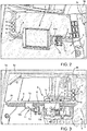
Figure 2 is a front perspective view of an inner portion of the cabin of the tractor offigure 1 according to a first embodiment of the present innovation; -
Figure 3 is a rear perspective view of an inner portion of the cabin of the tractor offigure 1 according to a first embodiment of the present innovation; -
Figure 4 is a front perspective view of an inner portion of the cabin of the tractor offigure 1 according to a second embodiment of the present innovation; and -
Figure 5 is a rear perspective view of an inner portion of the cabin of the tractor offigure 1 according to a second embodiment of the present innovation. -
Figure 1 discloses anagricultural vehicle 1 of known typology, e.g. a tractor, comprising acabin 2 including a plurality of walls 3 connected together to define aninner space 4 in which a seat for the user of thevehicle 1 is placed. - In greater detail, the
cabin 2 is defined by a plurality oflateral walls 3a, i.e. a right, a left, a rear and a front lateral wall, a roof 3b and a floor (not shown). As known, the right and leftlateral walls 3a are provided with openings to install windows whilefront wall 3a is provided with an opening which occupies almost theentire front wall 3a to house awindscreen 5. It is clear that the described cabin arrangement is exemplarily and thefront wall 3a may be absent and occupied entirely by awindscreen 5 fixed to theother walls 3a defining the cabin. - According to the present innovation, the
vehicle 1 comprises aholding system 6 carried by at least one of the walls 3 defining thecabin 2 and defining a plurality of holding positions along itself for electronic devices such as telephones, tablets, orcommand screens 7. - In greater particular, the
holding system 6 comprises asupport arm 8 comprising afirst extremity portion 8a configured to be fixed to the wall 3 of thecabin 2 and asecond extremity portion 8b configured to be fixed to such wall 3 or to another wall 3 of thecabin 2. - According to the described embodiments of
figures 2 to 5 , thesupport arm 8 is preferably L-shaped, i.e. comprises a first segment 8' parallel to the ground and asecond segment 8", perpendicular to the first segment 8'. The first segment 8' defines thefirst extremity portion 8a which is preferably fixed to alateral wall 3a of thecabin 2 while thesecond segment 8" defines asecond extremity portion 8b which is preferably fixed to a lateral wall 3b of thecabin 2. - Advantageously, the
support arm 8 is realized as one piece and in polymeric material, such as in plastic. - According to an aspect of the present innovation, the
holding system 6 is provided with a holding element configured to be selectively fixed along saidsupport arm 8 in order to define a plurality of fixation position for said electronic devices. - In particular, the
support arm 8 is provided withgrooves 9 configured to define a path along thesupport arm 8 itself and theholding element 10 is configured to slide withinsuch grooves 9 along the path defined along thesupport arm 8. - According to the described embodiments of
figures 2 to 5 , thegrooves 9 are realized in the first segment 8' along the entire length of this latter and are substantially parallel to ground once thesystem 6 is mounted on the vehicle. Moreover, thegrooves 9 are preferably twogrooves 9, i.e. anupper groove 9 and alower groove 9 for each face of the first segment 8', i.e. there are twogrooves 9 directed towards theinner space 4 and two grooves faced towindscreen 6. - The two pairs of
grooves 9 are at the same vertical position with respect to first segment 8', thereby defining a sort of rail along this latter. Theholding element 10 is configured to slide along such rail defined by the two pairs ofgrooves 9 and comprises coupling means 11 configured to selectively fix theholding element 10 on a chosen position along thefirst segment 8. - In particular, on both the described embodiments the
holding element 10 comprises a front and arear portions front portion 10a being shaped to cooperate withfront grooves 9 and therear portion 10b being shaped to cooperate withrear grooves 9. The front and therear portions pin 12 which allows a relative movement ofportions such pin 12. Accordingly,portions pin 12. - According to the above described arrangement, the coupling means 11 comprises a
handle 13 coupled topin 12 and configured to regulate the distance betweenportions handle 13 can be coupled topin 12 to produce the above effect thanks to any known mechanical means, e.g. via threaded means or springs. - According to the above, the
holding element 10 may be designed so that the maximum distance betweenportions grooves 9 and the minimum distance is provided to allow the fixing of theholding element 10 because of the friction engagement ofportions - As clearly shown in the embodiments of
figure 2, 3 and4, 5 theholding element 10 may be coupled togrooves 9 so that they protrude above the first segment 8' or below this latter, according the necessity of the user and the typology of electronic devices that it is needed to be carried. - It is clear that two
holding elements 10 are shown, but it is clear that theholding system 6 may also carry only a only one or more than twoholding elements 10. - According to the described embodiments of
figures 2 to 5 , theholding element 10 is provided with asupport plate 14 configured to allow the fixation of theelectronic device 7. Preferably,such support plate 14 is carried by one of theportions electronic device 10. - According to the above arrangement the
support plate 14 is supported bypin 12 and, advantageously, via a ball joint realized between thesupport plate 14 and aterminal ball portion 15 of thepin 12 so that thesupport plate 14 can be easily positioned around the axis ofpin 12. - According to the first embodiment of the present innovation, shown in
figures 2 and 3 , thesupport arm 8 is preferably hollow and it is dimensioned to allow the passage of electrical or signal cables inside itself. Accordingly, thesupport arm 8 is provided with at least asocket 16 configured to allow such cables to come out from the volume defined by thesupport arm 8 to be connected to an electronic device and provide to this latter power and/or communication signals. Such cables, obviously, are connected to a source of electrical power and/or of communications signals of thevehicle 1. - In particular, according to the described embodiment, the
support arm 8 definessuch socket 6 realized in thesecond segment 8". Preferably, thesupport arm 8 defines threesockets 6 on both its rear and front face. Preferably, the threesockets 6 on the rear face are aligned along thesecond segment 8" and, similarly the threesockets 6 on the front face are aligned along thesecond segment 8". Preferably,sockets 6 on front face are coaxial withsockets 6 realized on rear face of thesupport arm 8. - According to the second embodiment of the present innovation, shown in
figures 4 and 5 , thesupport arm 8 comprises a fixedholding element 20 configured to be carried bysupport arm 8 and to be fixed to one of the walls 3 of thecabin 2. - In the described embodiment, such fixed
holding element 20 is carried by first segment 8' and fixed tolateral wall 3a of thecabin 2. - Such fixed
holding element 20 is configured to carry electric connection means 21, such one or more USB ports, in order to allow the electrical/signal communication of theelectronic devices 7 with a source of electrical power or to a source of communication signals. - Furthermore, as shown in such second embodiment, the
holding elements 10 may be fixed on opposite positions according to a plan defined by the longitudinal axis of first portion 8' ofsupport arm 8, according to user's necessities. - The operation of an
agricultural vehicle 1 provided with aholding system 6 as described above is the following. - The user of the vehicle can couple or decouple to the
support plate 14 any kind ofelectronic device 7. When coupled, the user may decoupleportions element 10 to allow the sliding of this latter along thesupport arm 8 and may movesupport plate 14 to regulate the inclination along an axis perpendicular to the aforementioned sliding path. Once the required position is reached, the user can fix theholding element 10 thanks to the coupling means 11 so that theholding element 10 cannot move during the working operations of the vehicle. - In view of the foregoing, the advantages of a
work vehicle 1 provided with aholding system 6 according to the innovation are apparent. - Thanks to the proposed
holding system 6 the user can fixelectronic devices 7 in different points according to its best comfort position. - Furthermore, the proposed system is particularly inexpensive and versatile. Indeed, the realization with a "L-shape" allows the fixation of the
support arm 8 at left or right side of thevehicle 1 without requiring any further modification to the holding system. - Again, the holding
elements 10 are easy to fix and move along thesupport arm 8, thereby guaranteeing a quick setting of the disposition of electronic devices according to the comfort of the user. - Furthermore, the two different possibilities for providing power and/or signals allow the use of the holding system with different typologies of
vehicles 1. - It is clear that modifications can be made to the described
work vehicle 1 provided with aholding system 6 which do not extend beyond the scope of protection defined by the claims. - For example, the shapes of
support arm 8, holdingelement 10 or supportingplate 15 may be varied according to the typology and dimensions of the vehicle. - Furthermore, it is clear that coupling means 10, the fixing points of
support arm 8 or the ball joint 13 may be substituted by equivalent devices.
Claims (11)
- Work vehicle (1) including a cabin (2) defined by a plurality of walls (3) and a windscreen (5) delimiting an inner space (4) configured to accommodate a user of said work vehicle (1), said work vehicle (1) comprising a holding system (6) carried by at least one of said walls (3) inside said inner space (4) in face of said windscreen (5), said holding system (6) being configured to define a plurality of holding positions for electronic devices (7) to be used by said user.
- Work vehicle according to claim 1, wherein said holding system (6) comprises a support arm (8) comprising at least an extremity portion (8a, 8b) configured to allow the fixation of said support arm (8) to one of said walls (3) and at least a holding element (10), each configured to be selectively fixed along said support arm (8) and to define a support for an electronic device (7).
- Work vehicle according to claim 2, wherein said support arm (8) defines at least two grooves (9) defining a path along said support arm (8), said holding element (10) being configured to slide within said grooves (9) along said path.
- Work vehicle according to claim 2 or 3, wherein said support arm (8) is L-shaped and comprises a first portion (8') parallel to ground and a second portion (8") perpendicular to said first portion (8'), said first portion (8') comprising a first extremity portion (8a) configured to be fixed to a first wall (3a) of said cabin (2) and said second portion (8") comprising a second extremity portion (8b) configured to be fixed to a second wall (3b) of said cabin (2).
- Work vehicle according to claims 4 and 3, wherein said grooves (9) are realized in said first extremity portion (8a).
- Work vehicle according to any of claim 2 to 5, wherein said support arm (8) is hollow and configured to allow the passage of cables within itself, said cables being connected to a source of power and/or signal of said work vehicle (1) to provide power and/or signal to said electronic devices (7).
- Work vehicle according to claim 6, wherein said support arm (8) comprises sockets (16) configured to allow the passage of said cables from the inner space defined by said support arm (8) to said inner space (4) defined by said cabin (2) .
- Work vehicle according to any of claims 2 to 5, comprising a fixed holding element (20) carried by said support arm (8) and/or one of said walls (3) and configured to carry electrical connection means (21) connected to a source of power and/or signal of said work vehicle (1) to provide power and/or signal to said electronic devices (7).
- Work vehicle according to any of claims 2 to 8, wherein said holding element (10) comprises a support plate (15) configured to allow the connection of an electronic device (7).
- Work vehicle according to any of claims 2 to 9, wherein said holding element (10) comprises a first portion (10a) configured to cooperate with a side of said support arm (8) and a second portion (10b) configured to cooperate with an opposite side of said support arm (8), said first and second portions (10a, 10b) being connected together by a pin (12), said holding element (10) further comprising coupling means (11) configured to move away said first and second portions (10a, 10b) along said pin (12) and to clamp together said first and second portions (10a, 10b) to said support arm, moving these latter along said pin (12).
- Work vehicle according to claim 9 and 10, wherein said support plate (14) is coupled to said pin (12) via a ball joint (13).
Applications Claiming Priority (1)
| Application Number | Priority Date | Filing Date | Title |
|---|---|---|---|
| IT201900003822 | 2019-10-24 |
Publications (2)
| Publication Number | Publication Date |
|---|---|
| EP3812214A1 true EP3812214A1 (en) | 2021-04-28 |
| EP3812214B1 EP3812214B1 (en) | 2022-10-05 |
Family
ID=73014414
Family Applications (1)
| Application Number | Title | Priority Date | Filing Date |
|---|---|---|---|
| EP20203769.3A Active EP3812214B1 (en) | 2019-10-24 | 2020-10-26 | Commercial vehicle with holding system for electronic devices |
Country Status (1)
| Country | Link |
|---|---|
| EP (1) | EP3812214B1 (en) |
Cited By (1)
| Publication number | Priority date | Publication date | Assignee | Title |
|---|---|---|---|---|
| EP4385825A1 (en) * | 2022-12-15 | 2024-06-19 | AGCO International GmbH | Device mounting system for cab |
Citations (5)
| Publication number | Priority date | Publication date | Assignee | Title |
|---|---|---|---|---|
| US20040084920A1 (en) * | 2001-05-01 | 2004-05-06 | Johnson Controls Technology Company | Security system for a modular system in a vehicle |
| FR2895713A1 (en) * | 2006-01-05 | 2007-07-06 | Peugeot Citroen Automobiles Sa | Function e.g. rear view function, facilitating equipment for motor vehicle, has displacement unit moving device to backward position, when vehicle moves front, to allow screen to be visible to passengers and not visible to driver |
| US20110068241A1 (en) * | 2009-09-21 | 2011-03-24 | Suddarth Wesley Allison | Vertical display mounting device |
| WO2014186870A1 (en) * | 2013-05-23 | 2014-11-27 | Polycom Design Inc. | Apparatus for imaging the passenger compartment of a vehicle |
| US20180178648A1 (en) * | 2016-12-28 | 2018-06-28 | Cnh Industrial America Llc | Slidable mounting assembly for a work vehicle |
-
2020
- 2020-10-26 EP EP20203769.3A patent/EP3812214B1/en active Active
Patent Citations (5)
| Publication number | Priority date | Publication date | Assignee | Title |
|---|---|---|---|---|
| US20040084920A1 (en) * | 2001-05-01 | 2004-05-06 | Johnson Controls Technology Company | Security system for a modular system in a vehicle |
| FR2895713A1 (en) * | 2006-01-05 | 2007-07-06 | Peugeot Citroen Automobiles Sa | Function e.g. rear view function, facilitating equipment for motor vehicle, has displacement unit moving device to backward position, when vehicle moves front, to allow screen to be visible to passengers and not visible to driver |
| US20110068241A1 (en) * | 2009-09-21 | 2011-03-24 | Suddarth Wesley Allison | Vertical display mounting device |
| WO2014186870A1 (en) * | 2013-05-23 | 2014-11-27 | Polycom Design Inc. | Apparatus for imaging the passenger compartment of a vehicle |
| US20180178648A1 (en) * | 2016-12-28 | 2018-06-28 | Cnh Industrial America Llc | Slidable mounting assembly for a work vehicle |
Cited By (3)
| Publication number | Priority date | Publication date | Assignee | Title |
|---|---|---|---|---|
| EP4385825A1 (en) * | 2022-12-15 | 2024-06-19 | AGCO International GmbH | Device mounting system for cab |
| US20240198921A1 (en) * | 2022-12-15 | 2024-06-20 | Agco International Gmbh | Device Mounting System for Cab |
| US12606102B2 (en) * | 2022-12-15 | 2026-04-21 | Agco International Gmbh | Device mounting system for cab |
Also Published As
| Publication number | Publication date |
|---|---|
| EP3812214B1 (en) | 2022-10-05 |
Similar Documents
| Publication | Publication Date | Title |
|---|---|---|
| US8025348B2 (en) | Support element for securing in a furniture carcass | |
| US7152488B2 (en) | System operating unit | |
| US8180279B2 (en) | Wireless hotspot arrangement | |
| KR101589580B1 (en) | Multi-beam antenna with multi-device control unit | |
| US20120164973A1 (en) | Personal Communication Device RF Zone Billing Arrangement | |
| EP4002578A1 (en) | Clamping apparatus for antenna | |
| EP3798053B1 (en) | Cab for a construction machine | |
| EP3812214B1 (en) | Commercial vehicle with holding system for electronic devices | |
| DE102007044294B4 (en) | Holder for a mobile telephone with an antenna array | |
| US3394287A (en) | Frames for electrical communication apparatus | |
| DE102017203429A1 (en) | Electrical appliances module | |
| US5847340A (en) | Power switch mutually locking arrangement | |
| US6259604B1 (en) | Receiving housing | |
| KR100979773B1 (en) | Distributing board | |
| KR20100103293A (en) | Surveillance camera system | |
| KR101601002B1 (en) | Distributing board for power distributing connection of an underground power line | |
| KR20200137446A (en) | Slide Switch Unit | |
| CN102132000A (en) | Housing for at least partially accommodating furniture accessories | |
| US20030137723A1 (en) | Transmission device for a surgical microscope | |
| JPS609678B2 (en) | Casing for housing constituent units and equipment of directional wireless communication equipment | |
| US20120049576A1 (en) | Motor Vehicle Glass | |
| WO2014095160A1 (en) | Implement control on vehicle | |
| ITMI950027U1 (en) | ADAPTER FOR A PORTABLE RADIO COMMUNICATION EQUIPMENT | |
| US8063733B2 (en) | Device for communicating with a system | |
| CN210838817U (en) | Wiring box |
Legal Events
| Date | Code | Title | Description |
|---|---|---|---|
| PUAI | Public reference made under article 153(3) epc to a published international application that has entered the european phase |
Free format text: ORIGINAL CODE: 0009012 |
|
| STAA | Information on the status of an ep patent application or granted ep patent |
Free format text: STATUS: THE APPLICATION HAS BEEN PUBLISHED |
|
| AK | Designated contracting states |
Kind code of ref document: A1 Designated state(s): AL AT BE BG CH CY CZ DE DK EE ES FI FR GB GR HR HU IE IS IT LI LT LU LV MC MK MT NL NO PL PT RO RS SE SI SK SM TR |
|
| AX | Request for extension of the european patent |
Extension state: BA ME |
|
| STAA | Information on the status of an ep patent application or granted ep patent |
Free format text: STATUS: REQUEST FOR EXAMINATION WAS MADE |
|
| 17P | Request for examination filed |
Effective date: 20211028 |
|
| RBV | Designated contracting states (corrected) |
Designated state(s): AL AT BE BG CH CY CZ DE DK EE ES FI FR GB GR HR HU IE IS IT LI LT LU LV MC MK MT NL NO PL PT RO RS SE SI SK SM TR |
|
| GRAP | Despatch of communication of intention to grant a patent |
Free format text: ORIGINAL CODE: EPIDOSNIGR1 |
|
| STAA | Information on the status of an ep patent application or granted ep patent |
Free format text: STATUS: GRANT OF PATENT IS INTENDED |
|
| INTG | Intention to grant announced |
Effective date: 20220428 |
|
| GRAS | Grant fee paid |
Free format text: ORIGINAL CODE: EPIDOSNIGR3 |
|
| GRAA | (expected) grant |
Free format text: ORIGINAL CODE: 0009210 |
|
| STAA | Information on the status of an ep patent application or granted ep patent |
Free format text: STATUS: THE PATENT HAS BEEN GRANTED |
|
| AK | Designated contracting states |
Kind code of ref document: B1 Designated state(s): AL AT BE BG CH CY CZ DE DK EE ES FI FR GB GR HR HU IE IS IT LI LT LU LV MC MK MT NL NO PL PT RO RS SE SI SK SM TR |
|
| REG | Reference to a national code |
Ref country code: GB Ref legal event code: FG4D |
|
| REG | Reference to a national code |
Ref country code: CH Ref legal event code: EP |
|
| REG | Reference to a national code |
Ref country code: AT Ref legal event code: REF Ref document number: 1522570 Country of ref document: AT Kind code of ref document: T Effective date: 20221015 |
|
| REG | Reference to a national code |
Ref country code: IE Ref legal event code: FG4D |
|
| REG | Reference to a national code |
Ref country code: DE Ref legal event code: R096 Ref document number: 602020005470 Country of ref document: DE |
|
| REG | Reference to a national code |
Ref country code: LT Ref legal event code: MG9D |
|
| REG | Reference to a national code |
Ref country code: NL Ref legal event code: MP Effective date: 20221005 |
|
| REG | Reference to a national code |
Ref country code: AT Ref legal event code: MK05 Ref document number: 1522570 Country of ref document: AT Kind code of ref document: T Effective date: 20221005 |
|
| PG25 | Lapsed in a contracting state [announced via postgrant information from national office to epo] |
Ref country code: NL Free format text: LAPSE BECAUSE OF FAILURE TO SUBMIT A TRANSLATION OF THE DESCRIPTION OR TO PAY THE FEE WITHIN THE PRESCRIBED TIME-LIMIT Effective date: 20221005 |
|
| PG25 | Lapsed in a contracting state [announced via postgrant information from national office to epo] |
Ref country code: SE Free format text: LAPSE BECAUSE OF FAILURE TO SUBMIT A TRANSLATION OF THE DESCRIPTION OR TO PAY THE FEE WITHIN THE PRESCRIBED TIME-LIMIT Effective date: 20221005 Ref country code: PT Free format text: LAPSE BECAUSE OF FAILURE TO SUBMIT A TRANSLATION OF THE DESCRIPTION OR TO PAY THE FEE WITHIN THE PRESCRIBED TIME-LIMIT Effective date: 20230206 Ref country code: NO Free format text: LAPSE BECAUSE OF FAILURE TO SUBMIT A TRANSLATION OF THE DESCRIPTION OR TO PAY THE FEE WITHIN THE PRESCRIBED TIME-LIMIT Effective date: 20230105 Ref country code: LT Free format text: LAPSE BECAUSE OF FAILURE TO SUBMIT A TRANSLATION OF THE DESCRIPTION OR TO PAY THE FEE WITHIN THE PRESCRIBED TIME-LIMIT Effective date: 20221005 Ref country code: FI Free format text: LAPSE BECAUSE OF FAILURE TO SUBMIT A TRANSLATION OF THE DESCRIPTION OR TO PAY THE FEE WITHIN THE PRESCRIBED TIME-LIMIT Effective date: 20221005 Ref country code: ES Free format text: LAPSE BECAUSE OF FAILURE TO SUBMIT A TRANSLATION OF THE DESCRIPTION OR TO PAY THE FEE WITHIN THE PRESCRIBED TIME-LIMIT Effective date: 20221005 Ref country code: AT Free format text: LAPSE BECAUSE OF FAILURE TO SUBMIT A TRANSLATION OF THE DESCRIPTION OR TO PAY THE FEE WITHIN THE PRESCRIBED TIME-LIMIT Effective date: 20221005 |
|
| PG25 | Lapsed in a contracting state [announced via postgrant information from national office to epo] |
Ref country code: RS Free format text: LAPSE BECAUSE OF FAILURE TO SUBMIT A TRANSLATION OF THE DESCRIPTION OR TO PAY THE FEE WITHIN THE PRESCRIBED TIME-LIMIT Effective date: 20221005 Ref country code: PL Free format text: LAPSE BECAUSE OF FAILURE TO SUBMIT A TRANSLATION OF THE DESCRIPTION OR TO PAY THE FEE WITHIN THE PRESCRIBED TIME-LIMIT Effective date: 20221005 Ref country code: LV Free format text: LAPSE BECAUSE OF FAILURE TO SUBMIT A TRANSLATION OF THE DESCRIPTION OR TO PAY THE FEE WITHIN THE PRESCRIBED TIME-LIMIT Effective date: 20221005 Ref country code: IS Free format text: LAPSE BECAUSE OF FAILURE TO SUBMIT A TRANSLATION OF THE DESCRIPTION OR TO PAY THE FEE WITHIN THE PRESCRIBED TIME-LIMIT Effective date: 20230205 Ref country code: HR Free format text: LAPSE BECAUSE OF FAILURE TO SUBMIT A TRANSLATION OF THE DESCRIPTION OR TO PAY THE FEE WITHIN THE PRESCRIBED TIME-LIMIT Effective date: 20221005 Ref country code: GR Free format text: LAPSE BECAUSE OF FAILURE TO SUBMIT A TRANSLATION OF THE DESCRIPTION OR TO PAY THE FEE WITHIN THE PRESCRIBED TIME-LIMIT Effective date: 20230106 |
|
| REG | Reference to a national code |
Ref country code: BE Ref legal event code: MM Effective date: 20221031 |
|
| RAP4 | Party data changed (patent owner data changed or rights of a patent transferred) |
Owner name: CNH INDUSTRIAL ITALIA S.P.A. |
|
| PG25 | Lapsed in a contracting state [announced via postgrant information from national office to epo] |
Ref country code: LU Free format text: LAPSE BECAUSE OF NON-PAYMENT OF DUE FEES Effective date: 20221026 |
|
| REG | Reference to a national code |
Ref country code: DE Ref legal event code: R097 Ref document number: 602020005470 Country of ref document: DE |
|
| PG25 | Lapsed in a contracting state [announced via postgrant information from national office to epo] |
Ref country code: SM Free format text: LAPSE BECAUSE OF FAILURE TO SUBMIT A TRANSLATION OF THE DESCRIPTION OR TO PAY THE FEE WITHIN THE PRESCRIBED TIME-LIMIT Effective date: 20221005 Ref country code: RO Free format text: LAPSE BECAUSE OF FAILURE TO SUBMIT A TRANSLATION OF THE DESCRIPTION OR TO PAY THE FEE WITHIN THE PRESCRIBED TIME-LIMIT Effective date: 20221005 Ref country code: MC Free format text: LAPSE BECAUSE OF FAILURE TO SUBMIT A TRANSLATION OF THE DESCRIPTION OR TO PAY THE FEE WITHIN THE PRESCRIBED TIME-LIMIT Effective date: 20221005 Ref country code: EE Free format text: LAPSE BECAUSE OF FAILURE TO SUBMIT A TRANSLATION OF THE DESCRIPTION OR TO PAY THE FEE WITHIN THE PRESCRIBED TIME-LIMIT Effective date: 20221005 Ref country code: DK Free format text: LAPSE BECAUSE OF FAILURE TO SUBMIT A TRANSLATION OF THE DESCRIPTION OR TO PAY THE FEE WITHIN THE PRESCRIBED TIME-LIMIT Effective date: 20221005 Ref country code: CZ Free format text: LAPSE BECAUSE OF FAILURE TO SUBMIT A TRANSLATION OF THE DESCRIPTION OR TO PAY THE FEE WITHIN THE PRESCRIBED TIME-LIMIT Effective date: 20221005 |
|
| PLBE | No opposition filed within time limit |
Free format text: ORIGINAL CODE: 0009261 |
|
| STAA | Information on the status of an ep patent application or granted ep patent |
Free format text: STATUS: NO OPPOSITION FILED WITHIN TIME LIMIT |
|
| PG25 | Lapsed in a contracting state [announced via postgrant information from national office to epo] |
Ref country code: SK Free format text: LAPSE BECAUSE OF FAILURE TO SUBMIT A TRANSLATION OF THE DESCRIPTION OR TO PAY THE FEE WITHIN THE PRESCRIBED TIME-LIMIT Effective date: 20221005 Ref country code: AL Free format text: LAPSE BECAUSE OF FAILURE TO SUBMIT A TRANSLATION OF THE DESCRIPTION OR TO PAY THE FEE WITHIN THE PRESCRIBED TIME-LIMIT Effective date: 20221005 |
|
| 26N | No opposition filed |
Effective date: 20230706 |
|
| PG25 | Lapsed in a contracting state [announced via postgrant information from national office to epo] |
Ref country code: BE Free format text: LAPSE BECAUSE OF NON-PAYMENT OF DUE FEES Effective date: 20221031 |
|
| PG25 | Lapsed in a contracting state [announced via postgrant information from national office to epo] |
Ref country code: IE Free format text: LAPSE BECAUSE OF NON-PAYMENT OF DUE FEES Effective date: 20221026 |
|
| PG25 | Lapsed in a contracting state [announced via postgrant information from national office to epo] |
Ref country code: SI Free format text: LAPSE BECAUSE OF FAILURE TO SUBMIT A TRANSLATION OF THE DESCRIPTION OR TO PAY THE FEE WITHIN THE PRESCRIBED TIME-LIMIT Effective date: 20221005 |
|
| PG25 | Lapsed in a contracting state [announced via postgrant information from national office to epo] |
Ref country code: CY Free format text: LAPSE BECAUSE OF FAILURE TO SUBMIT A TRANSLATION OF THE DESCRIPTION OR TO PAY THE FEE WITHIN THE PRESCRIBED TIME-LIMIT Effective date: 20221005 |
|
| PG25 | Lapsed in a contracting state [announced via postgrant information from national office to epo] |
Ref country code: MK Free format text: LAPSE BECAUSE OF FAILURE TO SUBMIT A TRANSLATION OF THE DESCRIPTION OR TO PAY THE FEE WITHIN THE PRESCRIBED TIME-LIMIT Effective date: 20221005 |
|
| REG | Reference to a national code |
Ref country code: CH Ref legal event code: PL |
|
| PG25 | Lapsed in a contracting state [announced via postgrant information from national office to epo] |
Ref country code: CH Free format text: LAPSE BECAUSE OF NON-PAYMENT OF DUE FEES Effective date: 20231031 |
|
| PG25 | Lapsed in a contracting state [announced via postgrant information from national office to epo] |
Ref country code: HU Free format text: LAPSE BECAUSE OF FAILURE TO SUBMIT A TRANSLATION OF THE DESCRIPTION OR TO PAY THE FEE WITHIN THE PRESCRIBED TIME-LIMIT; INVALID AB INITIO Effective date: 20201026 Ref country code: CH Free format text: LAPSE BECAUSE OF NON-PAYMENT OF DUE FEES Effective date: 20231031 Ref country code: BG Free format text: LAPSE BECAUSE OF FAILURE TO SUBMIT A TRANSLATION OF THE DESCRIPTION OR TO PAY THE FEE WITHIN THE PRESCRIBED TIME-LIMIT Effective date: 20221005 |
|
| PG25 | Lapsed in a contracting state [announced via postgrant information from national office to epo] |
Ref country code: MT Free format text: LAPSE BECAUSE OF FAILURE TO SUBMIT A TRANSLATION OF THE DESCRIPTION OR TO PAY THE FEE WITHIN THE PRESCRIBED TIME-LIMIT Effective date: 20221005 |
|
| PG25 | Lapsed in a contracting state [announced via postgrant information from national office to epo] |
Ref country code: TR Free format text: LAPSE BECAUSE OF FAILURE TO SUBMIT A TRANSLATION OF THE DESCRIPTION OR TO PAY THE FEE WITHIN THE PRESCRIBED TIME-LIMIT Effective date: 20221005 |
|
| PGFP | Annual fee paid to national office [announced via postgrant information from national office to epo] |
Ref country code: DE Payment date: 20251028 Year of fee payment: 6 |
|
| PGFP | Annual fee paid to national office [announced via postgrant information from national office to epo] |
Ref country code: GB Payment date: 20251021 Year of fee payment: 6 |
|
| PGFP | Annual fee paid to national office [announced via postgrant information from national office to epo] |
Ref country code: IT Payment date: 20251024 Year of fee payment: 6 |
|
| PGFP | Annual fee paid to national office [announced via postgrant information from national office to epo] |
Ref country code: FR Payment date: 20251027 Year of fee payment: 6 |
|
| PG25 | Lapsed in a contracting state [announced via postgrant information from national office to epo] |
Ref country code: CH Free format text: THE PATENT HAS BEEN ANNULLED BY A DECISION OF A NATIONAL AUTHORITY Effective date: 20231031 |