EP3811860A1 - Ambient light signal adjustment method, chip and electronic equipment - Google Patents
Ambient light signal adjustment method, chip and electronic equipment Download PDFInfo
- Publication number
- EP3811860A1 EP3811860A1 EP20199848.1A EP20199848A EP3811860A1 EP 3811860 A1 EP3811860 A1 EP 3811860A1 EP 20199848 A EP20199848 A EP 20199848A EP 3811860 A1 EP3811860 A1 EP 3811860A1
- Authority
- EP
- European Patent Office
- Prior art keywords
- ambient light
- light signal
- intensity
- signal
- cancellation circuit
- Prior art date
- Legal status (The legal status is an assumption and is not a legal conclusion. Google has not performed a legal analysis and makes no representation as to the accuracy of the status listed.)
- Granted
Links
Images


Classifications
-
- G—PHYSICS
- G01—MEASURING; TESTING
- G01J—MEASUREMENT OF INTENSITY, VELOCITY, SPECTRAL CONTENT, POLARISATION, PHASE OR PULSE CHARACTERISTICS OF INFRARED, VISIBLE OR ULTRAVIOLET LIGHT; COLORIMETRY; RADIATION PYROMETRY
- G01J1/00—Photometry, e.g. photographic exposure meter
- G01J1/42—Photometry, e.g. photographic exposure meter using electric radiation detectors
- G01J1/4204—Photometry, e.g. photographic exposure meter using electric radiation detectors with determination of ambient light
-
- A—HUMAN NECESSITIES
- A61—MEDICAL OR VETERINARY SCIENCE; HYGIENE
- A61B—DIAGNOSIS; SURGERY; IDENTIFICATION
- A61B5/00—Measuring for diagnostic purposes; Identification of persons
- A61B5/02—Detecting, measuring or recording for evaluating the cardiovascular system, e.g. pulse, heart rate, blood pressure or blood flow
- A61B5/024—Measuring pulse rate or heart rate
- A61B5/02416—Measuring pulse rate or heart rate using photoplethysmograph signals, e.g. generated by infrared radiation
-
- A—HUMAN NECESSITIES
- A61—MEDICAL OR VETERINARY SCIENCE; HYGIENE
- A61B—DIAGNOSIS; SURGERY; IDENTIFICATION
- A61B5/00—Measuring for diagnostic purposes; Identification of persons
- A61B5/0059—Measuring for diagnostic purposes; Identification of persons using light, e.g. diagnosis by transillumination, diascopy, fluorescence
- A61B5/0082—Measuring for diagnostic purposes; Identification of persons using light, e.g. diagnosis by transillumination, diascopy, fluorescence adapted for particular medical purposes
-
- A—HUMAN NECESSITIES
- A61—MEDICAL OR VETERINARY SCIENCE; HYGIENE
- A61B—DIAGNOSIS; SURGERY; IDENTIFICATION
- A61B5/00—Measuring for diagnostic purposes; Identification of persons
- A61B5/02—Detecting, measuring or recording for evaluating the cardiovascular system, e.g. pulse, heart rate, blood pressure or blood flow
- A61B5/024—Measuring pulse rate or heart rate
- A61B5/02438—Measuring pulse rate or heart rate with portable devices, e.g. worn by the patient
-
- A—HUMAN NECESSITIES
- A61—MEDICAL OR VETERINARY SCIENCE; HYGIENE
- A61B—DIAGNOSIS; SURGERY; IDENTIFICATION
- A61B5/00—Measuring for diagnostic purposes; Identification of persons
- A61B5/02—Detecting, measuring or recording for evaluating the cardiovascular system, e.g. pulse, heart rate, blood pressure or blood flow
- A61B5/024—Measuring pulse rate or heart rate
- A61B5/02444—Details of sensor
-
- A—HUMAN NECESSITIES
- A61—MEDICAL OR VETERINARY SCIENCE; HYGIENE
- A61B—DIAGNOSIS; SURGERY; IDENTIFICATION
- A61B5/00—Measuring for diagnostic purposes; Identification of persons
- A61B5/145—Measuring characteristics of blood in vivo, e.g. gas concentration or pH-value ; Measuring characteristics of body fluids or tissues, e.g. interstitial fluid or cerebral tissue
- A61B5/1455—Measuring characteristics of blood in vivo, e.g. gas concentration or pH-value ; Measuring characteristics of body fluids or tissues, e.g. interstitial fluid or cerebral tissue using optical sensors, e.g. spectral photometrical oximeters
- A61B5/14551—Measuring characteristics of blood in vivo, e.g. gas concentration or pH-value ; Measuring characteristics of body fluids or tissues, e.g. interstitial fluid or cerebral tissue using optical sensors, e.g. spectral photometrical oximeters for measuring blood gases
-
- A—HUMAN NECESSITIES
- A61—MEDICAL OR VETERINARY SCIENCE; HYGIENE
- A61B—DIAGNOSIS; SURGERY; IDENTIFICATION
- A61B5/00—Measuring for diagnostic purposes; Identification of persons
- A61B5/68—Arrangements of detecting, measuring or recording means, e.g. sensors, in relation to patient
- A61B5/6801—Arrangements of detecting, measuring or recording means, e.g. sensors, in relation to patient specially adapted to be attached to or worn on the body surface
-
- A—HUMAN NECESSITIES
- A61—MEDICAL OR VETERINARY SCIENCE; HYGIENE
- A61B—DIAGNOSIS; SURGERY; IDENTIFICATION
- A61B5/00—Measuring for diagnostic purposes; Identification of persons
- A61B5/72—Signal processing specially adapted for physiological signals or for diagnostic purposes
- A61B5/7203—Signal processing specially adapted for physiological signals or for diagnostic purposes for noise prevention, reduction or removal
-
- A—HUMAN NECESSITIES
- A61—MEDICAL OR VETERINARY SCIENCE; HYGIENE
- A61B—DIAGNOSIS; SURGERY; IDENTIFICATION
- A61B5/00—Measuring for diagnostic purposes; Identification of persons
- A61B5/72—Signal processing specially adapted for physiological signals or for diagnostic purposes
- A61B5/7225—Details of analogue processing, e.g. isolation amplifier, gain or sensitivity adjustment, filtering, baseline or drift compensation
-
- A—HUMAN NECESSITIES
- A61—MEDICAL OR VETERINARY SCIENCE; HYGIENE
- A61B—DIAGNOSIS; SURGERY; IDENTIFICATION
- A61B5/00—Measuring for diagnostic purposes; Identification of persons
- A61B5/72—Signal processing specially adapted for physiological signals or for diagnostic purposes
- A61B5/7228—Signal modulation applied to the input signal sent to patient or subject; Demodulation to recover the physiological signal
-
- G—PHYSICS
- G01—MEASURING; TESTING
- G01J—MEASUREMENT OF INTENSITY, VELOCITY, SPECTRAL CONTENT, POLARISATION, PHASE OR PULSE CHARACTERISTICS OF INFRARED, VISIBLE OR ULTRAVIOLET LIGHT; COLORIMETRY; RADIATION PYROMETRY
- G01J1/00—Photometry, e.g. photographic exposure meter
- G01J1/42—Photometry, e.g. photographic exposure meter using electric radiation detectors
- G01J1/44—Electric circuits
-
- A—HUMAN NECESSITIES
- A61—MEDICAL OR VETERINARY SCIENCE; HYGIENE
- A61B—DIAGNOSIS; SURGERY; IDENTIFICATION
- A61B2560/00—Constructional details of operational features of apparatus; Accessories for medical measuring apparatus
- A61B2560/02—Operational features
- A61B2560/0204—Operational features of power management
-
- A—HUMAN NECESSITIES
- A61—MEDICAL OR VETERINARY SCIENCE; HYGIENE
- A61B—DIAGNOSIS; SURGERY; IDENTIFICATION
- A61B2560/00—Constructional details of operational features of apparatus; Accessories for medical measuring apparatus
- A61B2560/02—Operational features
- A61B2560/0223—Operational features of calibration, e.g. protocols for calibrating sensors
- A61B2560/0228—Operational features of calibration, e.g. protocols for calibrating sensors using calibration standards
- A61B2560/0233—Optical standards
-
- A—HUMAN NECESSITIES
- A61—MEDICAL OR VETERINARY SCIENCE; HYGIENE
- A61B—DIAGNOSIS; SURGERY; IDENTIFICATION
- A61B2560/00—Constructional details of operational features of apparatus; Accessories for medical measuring apparatus
- A61B2560/02—Operational features
- A61B2560/0242—Operational features adapted to measure environmental factors, e.g. temperature, pollution
- A61B2560/0247—Operational features adapted to measure environmental factors, e.g. temperature, pollution for compensation or correction of the measured physiological value
-
- A—HUMAN NECESSITIES
- A61—MEDICAL OR VETERINARY SCIENCE; HYGIENE
- A61B—DIAGNOSIS; SURGERY; IDENTIFICATION
- A61B2562/00—Details of sensors; Constructional details of sensor housings or probes; Accessories for sensors
- A61B2562/02—Details of sensors specially adapted for in-vivo measurements
- A61B2562/0233—Special features of optical sensors or probes classified in A61B5/00
- A61B2562/0238—Optical sensor arrangements for performing transmission measurements on body tissue
-
- A—HUMAN NECESSITIES
- A61—MEDICAL OR VETERINARY SCIENCE; HYGIENE
- A61B—DIAGNOSIS; SURGERY; IDENTIFICATION
- A61B2562/00—Details of sensors; Constructional details of sensor housings or probes; Accessories for sensors
- A61B2562/18—Shielding or protection of sensors from environmental influences, e.g. protection from mechanical damage
- A61B2562/185—Optical shielding, e.g. baffles
-
- A—HUMAN NECESSITIES
- A61—MEDICAL OR VETERINARY SCIENCE; HYGIENE
- A61B—DIAGNOSIS; SURGERY; IDENTIFICATION
- A61B5/00—Measuring for diagnostic purposes; Identification of persons
- A61B5/68—Arrangements of detecting, measuring or recording means, e.g. sensors, in relation to patient
- A61B5/6801—Arrangements of detecting, measuring or recording means, e.g. sensors, in relation to patient specially adapted to be attached to or worn on the body surface
- A61B5/6802—Sensor mounted on worn items
- A61B5/6803—Head-worn items, e.g. helmets, masks, headphones or goggles
-
- A—HUMAN NECESSITIES
- A61—MEDICAL OR VETERINARY SCIENCE; HYGIENE
- A61B—DIAGNOSIS; SURGERY; IDENTIFICATION
- A61B5/00—Measuring for diagnostic purposes; Identification of persons
- A61B5/68—Arrangements of detecting, measuring or recording means, e.g. sensors, in relation to patient
- A61B5/6801—Arrangements of detecting, measuring or recording means, e.g. sensors, in relation to patient specially adapted to be attached to or worn on the body surface
- A61B5/6802—Sensor mounted on worn items
- A61B5/681—Wristwatch-type devices
-
- A—HUMAN NECESSITIES
- A61—MEDICAL OR VETERINARY SCIENCE; HYGIENE
- A61B—DIAGNOSIS; SURGERY; IDENTIFICATION
- A61B5/00—Measuring for diagnostic purposes; Identification of persons
- A61B5/68—Arrangements of detecting, measuring or recording means, e.g. sensors, in relation to patient
- A61B5/6801—Arrangements of detecting, measuring or recording means, e.g. sensors, in relation to patient specially adapted to be attached to or worn on the body surface
- A61B5/6813—Specially adapted to be attached to a specific body part
- A61B5/6814—Head
-
- A—HUMAN NECESSITIES
- A61—MEDICAL OR VETERINARY SCIENCE; HYGIENE
- A61B—DIAGNOSIS; SURGERY; IDENTIFICATION
- A61B5/00—Measuring for diagnostic purposes; Identification of persons
- A61B5/68—Arrangements of detecting, measuring or recording means, e.g. sensors, in relation to patient
- A61B5/6801—Arrangements of detecting, measuring or recording means, e.g. sensors, in relation to patient specially adapted to be attached to or worn on the body surface
- A61B5/6813—Specially adapted to be attached to a specific body part
- A61B5/6824—Arm or wrist
Definitions
- the present disclosure relates to the technical field of wearable devices and, in particular, to an ambient light signal adjustment method, a chip and electronic equipment.
- a sensor e.g., a sensor disposed in proximity to the human body, above the human body, or close to an external body surface of the human body in other ways
- the wearable device can not only monitor health status of a wearer's body for a long term, but also allow the wearer to perform normal daily activities, travelling and commuting, or participate in other activities.
- the health status of the human body monitored by such wearable device may include a heart rate, a blood oxygenation, an activity level, a blood pressure, a galvanic skin response, or other information about the wearer's body.
- detection on status of a wearer's human body using the wearable device is usually realized by photoelectric detection.
- detection of a heart rate of a human body light of a certain wavelength is transmitted by a light transmitter in the wearable device and is incident into a skin tissue. Upon reflection, scattering and absorption from the skin tissue, a part of the light can be emitted from the skin surface and received by a light receiver in the wearable device.
- a light intensity signal received by the light receiver also presents a pulsatile change accordingly.
- a photo plethysmor graph (PPG) indicating the blood volume of the subcutaneous tissue changing with a pulse can be obtained by means of converting the light intensity signal received by the light receiver into an electrical signal, and a heart rate value can be calculated from this.
- PPG photo plethysmor graph
- the present disclosure provides an ambient light signal adjustment method, a chip, and electronic equipment, which realize adjustment of an ambient light signal acquired by a PPG sensor, thereby ensuring accuracy of a wearable device to detect a physiological characteristic of a user.
- an embodiment of the present disclosure provides an ambient light signal adjustment method, including:
- the cancellation signal intensity of the ambient light cancellation circuit automatically to enable the intensity of the adjusted first ambient light signal to be within the preset range all the time, adjustment of the ambient light signal acquired by the PPG sensor is realized, thereby ensuring accuracy of a wearable device to detect a physiological characteristic of a user.
- the determining, according to an intensity of the first ambient light signal automatically, whether to turn on an ambient light cancellation circuit including:
- the adjusting a cancellation signal intensity of the ambient light cancellation circuit automatically according to the intensity of the first ambient light signal to enable an intensity of the adjusted first ambient light signal to be within a preset range includes:
- the ambient light signal adjustment method further includes:
- a physiological characteristic of a human body can be detected through the target light signal, thereby improving accuracy of detection.
- the cancellation signal intensity is in direct proportion to the intensity of the first ambient light signal
- the ambient light cancellation circuit includes a successive approximation loop and a digitally controlled current source, and the successive approximation loop is connected to the digitally controlled current source.
- an embodiment of the present disclosure provides a chip, including:
- the determining circuit is specifically configured to:
- the ambient light cancellation circuit is specifically configured to:
- the chip according to an embodiment of the present disclosure further includes a processor, the processor is configured to:
- the determining circuit includes a comparator.
- the ambient light cancellation circuit includes a successive approximation loop and a digitally controlled current source, where a first terminal of the successive approximation loop is connected to the determining circuit, and a second terminal of the successive approximation loop is connected to the digitally controlled current source
- the chip according to an embodiment of the present disclosure further includes an amplifier and a driver, where a terminal of the amplifier is connected to a light receiver, and the driver is connected to a light transmitter, the amplifier is configured to amplify a light signal received by the light receiver; and the driver is configured to drive the light transmitter to transmit a light signal.
- the chip according to an embodiment of the present disclosure further includes an analog-to-digital converter and a digital-to-analog converter, where the analog-to-digital converter is configured to convert an analog signal output by the amplifier into a digital signal, or convert an analog signal output by the ambient light cancellation circuit into a digital signal, the digital-to-analog converter is configured to convert a digital signal sent by a controller into an analog signal.
- the analog-to-digital converter is configured to convert an analog signal output by the amplifier into a digital signal, or convert an analog signal output by the ambient light cancellation circuit into a digital signal
- the digital-to-analog converter is configured to convert a digital signal sent by a controller into an analog signal.
- the photo plethysmor graph (PPG) sensor includes a light-emitting device and a photoelectric conversion device, and the chip further includes the photoelectric conversion device connected to the determining circuit.
- the light-emitting device is integrated in the chip.
- an embodiment of the present disclosure provides electronic equipment, including: the chip provided in the second aspect and an optional implementation of the second aspect.
- the present disclosure provides an ambient light signal adjustment method, a chip and electronic equipment, which allow for: receiving a first ambient light signal, where the first ambient light signal is an ambient light signal acquired and output by a photo plethysmor graph (PPG) sensor; then determining, according to an intensity of the first ambient light signal automatically, whether to turn on an ambient light cancellation circuit, where the ambient light cancellation circuit is configured to adjust the first ambient light signal according to the intensity of the first ambient light signal; and if it is determined to turn on the ambient light cancellation circuit, adjusting a cancellation signal intensity of the ambient light cancellation circuit automatically according to the intensity of the first ambient light signal to enable an intensity of the adjusted first ambient light signal to be within a preset range.
- PPG photo plethysmor graph
- the cancellation signal intensity of the ambient light cancellation circuit automatically to enable the intensity of the adjusted first ambient light signal to be within the preset range all the time, adjustment of the ambient light signal acquired by the PPG sensor is realized, thereby ensuring accuracy of a wearable device to detect a physiological characteristic of a user.
- the smart device also has more and more functions.
- a sensor e.g., a sensor disposed in proximity to, above or close to an external body surface of the human body in other ways
- the wearable device is not only convenient to wear but can also detect a variety of human health data at any time. At present, use of the wearable device to detect some health data of a wearer can be realized by photo detection.
- a signal light of certain wavelength is transmitted by a light transmitter in the wearable device to a wearer or an object to be detected, and the signal light is received by a light receiver, then the signal light received by the light receiver is analyzed to determine a characteristic of the wearer or the object to be detected.
- the present disclosure proposes an ambient light signal adjustment method, a chip and electronic equipment.
- the application scenario of the embodiment of the present disclosure is not limited to heart rate detection.
- it can also be used for a blood oxygen, an activity level, a blood pressure, a galvanic skin response, etc.
- the present disclosure only takes the heart rate detection as an example for introduction.
- An embodiment of the present disclosure can be applied to a heart rate detection chip.
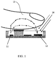
- FIG. 1 is a diagram illustrating an exemplary application scenario according to a technical solution of the present disclosure. As shown in FIG. 1 , light of a certain wavelength is transmitted by a light-emitting diode 11 and incident to a skin tissue 13, where, the light-emitting diode 11 can be one or more.
- Different light-emitting diodes 11 can be driven by one or more drivers in the heart rate detection chip, and the driver is connected to a dynamic control module in the heart rate detection chip. Different light-emitting diodes 11 can also emit light of different wavelengths, which is not limited in the embodiment of the present disclosure. After the light emitted by one or more light-emitting diodes 11 is reflected, scattered and absorbed by the skin tissue 13, part of the light can be emitted from the surface of the skin tissue 13 and received by a photodiode 12 of the heart rate detection chip. Through photoelectric conversion, the photodiode 12 can convert a received target light signal from a light signal into an electrical signal in terms of its form.
- the photodiode 12 can be one or more, and different photodiodes 12 can perform amplification through one or more amplifiers, and a target light signal amplified by the amplifier can be converted from an analog signal to a digital signal through an analog-to-digital conversion.
- a blood volume of the skin tissue 13 presents a pulsatile change responsive to a heart rhythm
- an intensity of the target light signal received by the photodiode 12 also presents a pulsatile change accordingly.
- a heart rate value is calculated.
- the photodiode 12 While the photodiode 12 is receiving the light emitted by the light-emitting diode 11, it also receives an ambient light signal 14 from the environment. Due to changes in the environment, if an intensity of the ambient light signal 14 is too strong, the target signal light received by the photodiode 12 will be affected, resulting in an inaccurate heart rate detection result, so the intensity of the received ambient light signal needs to be adjusted. Based on this, the embodiments of the present disclosure provide an ambient light signal adjustment method, a chip and electronic equipment.
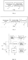
- FIG. 2 is a flowchart of an ambient light signal adjustment method according to an embodiment of the present disclosure, where the method can be realized by means of software and/or hardware, for example: it may be part of a terminal device or the entire terminal device, the terminal device may be a wearable device, such as a heart rate bracelet, a heart rate headset, a health bracelet, a health watch, a blood oxygen bracelet, a blood oxygen watch and other optical wearable devices; or it may be a medical device, a fitness device, a chip in a terminal device, etc., the following describes the ambient light signal adjustment method with the terminal device as an executive body. As shown in FIG.2 , the ambient light signal adjustment method according to the present disclosure includes the following steps.
- Step 101 Receiving a first ambient light signal.
- the first ambient light signal is an ambient light signal acquired and output by a PPG sensor.
- the first ambient light signal may be acquired before a light transmitter in the terminal device transmits a light signal.
- the first ambient light signal may be an original ambient light signal that has not been adjusted by an amplifier, or it may be an ambient light signal adjusted by the amplifier, which is not limited in the embodiment of the present disclosure.
- the first ambient light signal can be received by a light receiver in the terminal device, or the first ambient light signal transmitted by the PPG sensor may be received by a determining circuit, where the first ambient light signal transmitted by the PPG sensor is in an electrical signal form, and the embodiment of the present disclosure does not limit a specific way of receiving the first ambient light signal.
- the first ambient light signal can be represented by a light intensity signal, or the first ambient light signal can be converted into an electrical signal via a photoelectric conversion module, and an electrical signal can be used to represent the first ambient light signal. For example, a magnitude of current signal or a magnitude of voltage signal can be used to indicate an intensity of the first ambient light signal.
- the embodiment of the present disclosure does not limit a representation form of the first ambient light signal.
- Step 102 Determining, according to an intensity of the first ambient light signal automatically, whether to turn on an ambient light cancellation circuit, where the ambient light cancellation circuit is configured to adjust the first ambient light signal according to the intensity of the first ambient light signal.
- the terminal device may be in different environments.
- the first ambient light signal collected has different intensities.
- the intensity of the first ambient light signal is relatively small, which does not affect detection of a human physiological characteristic, so there is no need to process the ambient light signal.
- after the first ambient light signal is received there may be a need to adjust the first ambient light signal.
- the target light signal is a light signal which is transmitted by a light transmitter in the terminal device and which, after passing through a human body, is received by a light receiver.
- the ambient light cancellation circuit may include a digitally controlled current source and a successive approximation loop to realize cancellation of the first ambient light signal.
- the embodiment of the present disclosure does not limit a specific implementation of determining, according to the intensity of the first ambient light signal, whether to turn on the ambient light cancellation circuit.
- the determining, according to the intensity of the first ambient light signal, whether to turn on the ambient light cancellation circuit includes: if the intensity of the first ambient light signal is greater than a first preset threshold, turning on the ambient light cancellation circuit; if the intensity of the first ambient light signal is lower than or equal to the first preset threshold, not turning on the ambient light cancellation circuit.
- the implementation is simple, and by determining the intensity of the first ambient light signal, it is determined whether to turn on the ambient light cancellation circuit, avoiding introduction of new interference when the ambient light cancellation circuit is in an ON state all the time, thereby affecting a signal-to-noise ratio of the light signal, at the same time, avoiding impacts on a back-end circuit and a detection result due to a too strong intensity of the first ambient light signal when the ambient light canceling circuit is in an OFF state all the time or there is no ambient light canceling circuit.
- the embodiment of the present disclosure does not limit specific ranges and sizes of the set ON range, the set OFF range and the first preset threshold, provided that the intensity of the first ambient light signal can be used to determine whether there is a need to turn on the ambient light cancellation circuit so that detection accuracy can be improved.
- the first ambient light signal can be converted into an electrical signal in terms of form, and the intensity of the first ambient light signal can be indicated with a current of the electrical signal.
- the first preset threshold can take a maximum allowable current of the back-end circuit according to the embodiment of the present disclosure as a reference.
- the first preset threshold can be 50% of the maximum allowable current, which is not limited in the embodiment of the present disclosure.
- Step 103 If it is determined to turn on the ambient light cancellation circuit, adjusting a cancellation signal intensity of the ambient light cancellation circuit automatically according to the intensity of the first ambient light signal to enable an intensity of the adjusted first ambient light signal to be within a preset range.
- the embodiment of the present disclosure does not limit a specific implementation of how to automatically adjust a cancellation signal intensity of the ambient light cancellation circuit according to the intensity of the first ambient light signal, provided that the intensity of the adjusted first ambient light signal can be kept within a preset range all the time.
- the preset range can be realized by setting a preset maximum threshold and a preset minimum threshold.
- the embodiment of the present disclosure does not limit a specific range and implementation of the preset range, and setting can be made specifically according to user requirements.
- the adjusting the cancellation signal intensity of the ambient light cancellation circuit automatically according to the intensity of the first ambient light signal to enable the intensity of the adjusted first ambient light signal to be within a preset range includes: determining an electrical signal intensity of the first ambient light signal, where the electrical signal intensity of the first ambient light signal is an intensity after the first ambient light signal is converted into an electrical signal; and adjusting the cancellation signal intensity of the ambient light cancellation circuit dynamically to enable the intensity of the adjusted first ambient light signal to be lower than or equal to a second preset threshold, and obtaining a second ambient light signal, where the cancellation signal intensity is lower than or equal to the electrical signal intensity of the first ambient light signal.
- the electrical signal intensity of the first ambient light signal is an intensity after the first ambient light signal is converted into an electrical signal.
- the electrical signal of the first ambient light signal may be a current signal or a voltage signal, then the electrical signal intensity of the first ambient light signal is a magnitude of current or a magnitude of voltage.
- the embodiment of the present disclosure does not limit a type of the electrical signal of the first ambient light signal. For different environments, weather and other factors, the electrical signal intensity of the first ambient light signal acquired before each sampling may also be different.
- the cancellation signal intensity of the ambient light cancellation circuit can be dynamically adjusted, and the cancellation signal intensity is lower than or equal to the electrical signal intensity of the first ambient light signal, for example, the intensity of the cancellation signal is positively correlated with the intensity of the electrical signal of the first ambient light signal.
- the intensity of the cancellation signal is positively correlated with the intensity of the electrical signal of the first ambient light signal, such that the electrical signal intensity of the adjusted first ambient light signal is lower than or equal to the second preset threshold, or an electrical signal intensity of an adjusted second ambient light signal is within the preset range.
- the cancellation signal intensity of the ambient light cancellation circuit is dynamically adjusted through the electrical signal intensity of the first ambient light signal, thereby realizing dynamic adjustment for ambient light signals of different intensities, and improving reliability of ambient light signal adjustment.
- the embodiment of the present disclosure does not limit a value of the second preset threshold, provided that detection accuracy can be improved by adjusting the intensity of the first ambient light signal.
- the electrical signal intensity of the first ambient light signal is indicated with a current.
- the second preset threshold can take a maximum allowable current of the back-end circuit according to the embodiment of the present disclosure as a reference.
- the second preset threshold can be 10% of the maximum allowable current, which is not limited in the embodiment of the present disclosure.
- the cancellation signal intensity of the ambient light cancellation circuit automatically to enable the intensity of the adjusted first ambient light signal to be within the preset range all the time, adjustment of the ambient light signal acquired by the PPG sensor is realized, thereby ensuring accuracy of a wearable device to detect a physiological characteristic of a user.
- FIG. 3 is a flowchart of an ambient light signal adjustment method according to another embodiment of the present disclosure, where the method can be realized by means of software and/or hardware, for example: it may be part of a terminal device or the entire terminal device, the terminal device may be a wearable device, such as a heart rate bracelet, a heart rate headset, a health bracelet, a health watch, a blood oxygen bracelet, a blood oxygen watch and other optical wearable devices; or it may also be a medical device, a fitness device, a chip in a terminal device, etc., the following describes the ambient light signal adjustment method with the terminal device as an executive body. As shown in FIG. 3 , the ambient light signal adjustment method according to the present disclosure may further include the following steps.
- Step 201 Receiving a mixed light signal acquired and output by the PPG sensor, where the mixed light signal includes: a target light signal; and the first ambient light signal or the second ambient light signal.
- the mixed light signal can be a mixed light signal received by a light receiver in the terminal device, or the mixed light signal acquired and output by the PPG sensor through a transmission interface of a processor, where the mixed light signal output by the PPG sensor is an electrical signal in terms of form.
- the first ambient light signal is adjusted by the ambient light cancellation circuit to obtain a second ambient light signal.
- the mixed light signal includes a target light signal and the second ambient light signal. If it is determined to turn off the ambient light cancellation circuit, the first ambient light signal remains unchanged.
- the mixed light signal includes a target light signal and the first ambient light signal.
- the target light signal is a light signal which is transmitted by a light transmitter and which, after passing through a human body, is received by a light receiver, and the terminal device detects a physiological characteristic of a user by processing the target light signal.
- Step 202 Determining the target light signal through the mixed light signal and the first ambient light signal or determining the target light signal through the mixed light signal and the second ambient light signal.
- the target light signal can be obtained by subtracting the second ambient light signal from the mixed light signal. If the mixed light signal includes a target light signal and the first ambient light signal, then the target light signal can be obtained by subtracting the first ambient light signal from the mixed light signal.
- a physiological characteristic of a human body can be detected through the target light signal, which improves accuracy of detection.
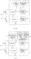
- FIG. 4 is a schematic structural diagram of a chip according to an embodiment of the present disclosure.
- the chip according to the embodiment of the present disclosure can include:
- the determining circuit 41 is specifically configured to: if the intensity of the first ambient light signal is greater than a first preset threshold, turn on the ambient light cancellation circuit; if the intensity of the first ambient light signal is lower than or equal to the first preset threshold, not turn on the ambient light cancellation circuit.
- the ambient light cancellation circuit 42 is specifically configured to: determine an electrical signal intensity of the first ambient light signal, where the electrical signal intensity of the first ambient light signal is an intensity after the first ambient light signal is converted into an electrical signal; and adjust the cancellation signal intensity of the ambient light cancellation circuit dynamically to enable the intensity of the adjusted first ambient light signal to be lower than or equal to a second preset threshold, and obtain a second ambient light signal, where the cancellation signal intensity is lower than or equal to the electrical signal intensity of the first ambient light signal.
- FIG. 5 is a schematic structural diagram of a chip according to a further embodiment of the present disclosure.
- the chip according to the embodiment of the present disclosure can further include: a processor 51, the processor 51 is configured to: receive a mixed light signal acquired and output by the PPG sensor, where the mixed light signal includes: a target light signal; and the first ambient light signal or the second ambient light signal; and where the target light signal is a light signal which is transmitted by a light transmitter and which, after passing through a human body, is received by a light receiver.
- FIG. 6A-FIG. 6B are schematic structural diagrams of a chip according to another embodiment of the present disclosure.
- the chip according to the embodiment of the present disclosure can further include: an amplifier 61 and a driver 62.
- the determining circuit 41 and the ambient light cancellation circuit 42 can be disposed between the amplifier 61 and a light receiver 65; as shown in FIG. 6B , the determining circuit 41 and the ambient light cancellation circuit 42 can also be disposed between the amplifier 61 and an analog-to-digital converter 63, the embodiment of the present disclosure does not limit this.
- a terminal of the amplifier 61 is connected to the light receiver 65, and the driver 62 is connected to a light transmitter 66.
- the amplifier 61 is configured to amplify a light signal received by the light receiver 65; and the driver 62 is configured to drive the light transmitter 66 to transmit a light signal.
- the chip according to the embodiment of the present disclosure further includes the analog-to-digital converter 63 and a digital-to-analog converter 64.
- the analog-to-digital converter 63 is configured to convert an analog signal output by the amplifier into a digital signal. As shown in FIG. 6B , the analog-to-digital converter 63 is configured to convert an analog signal output by the ambient light cancellation circuit into a digital signal. The digital-to-analog converter 64 is configured to convert a digital signal sent by a controller into an analog signal.
- FIG. 7 is a schematic structural diagram of a chip according to still another embodiment of the present disclosure.
- the determining circuit 41 includes a comparator 71.
- the embodiment of the present disclosure does not limit a specific circuit structure of the ambient light cancellation circuit.
- the ambient light cancellation circuit 42 includes a successive approximation loop 72 and a digitally controlled current source 73, where a first terminal of the successive approximation loop 72 is connected to the determining circuit 41, and a second terminal of the successive approximation loop 72 is connected to the digitally controlled current source 73.
- FIG. 8 is a schematic structural diagram of a chip according to yet still further embodiment of the present disclosure.
- the photo plethysmor graph (PPG) sensor includes a light-emitting device 81 and a photoelectric conversion device 82, and the chip also includes a photoelectric conversion device 82 connected to the determining circuit 41.
- PPG photo plethysmor graph
- FIG. 9 is a schematic structural diagram of a chip according to yet a further embodiment of the present disclosure. As shown in FIG. 9 , the light-emitting device 81 of the photo plethysmor graph (PPG) sensor is integrated in the chip.
- PPG photo plethysmor graph
- FIG. 10 is a schematic structural diagram of the electronic equipment according to an embodiment of the present disclosure. As shown in FIG. 10 , the electronic equipment according to the embodiment of the present disclosure includes the chip according to the above embodiments.
Landscapes
- Health & Medical Sciences (AREA)
- Life Sciences & Earth Sciences (AREA)
- Engineering & Computer Science (AREA)
- Physics & Mathematics (AREA)
- General Health & Medical Sciences (AREA)
- Veterinary Medicine (AREA)
- Animal Behavior & Ethology (AREA)
- Surgery (AREA)
- Public Health (AREA)
- Molecular Biology (AREA)
- Biophysics (AREA)
- Pathology (AREA)
- Biomedical Technology (AREA)
- Heart & Thoracic Surgery (AREA)
- Medical Informatics (AREA)
- Cardiology (AREA)
- Physiology (AREA)
- Signal Processing (AREA)
- Psychiatry (AREA)
- Computer Vision & Pattern Recognition (AREA)
- Artificial Intelligence (AREA)
- Spectroscopy & Molecular Physics (AREA)
- General Physics & Mathematics (AREA)
- Power Engineering (AREA)
- Sustainable Development (AREA)
- Optics & Photonics (AREA)
- Measurement Of The Respiration, Hearing Ability, Form, And Blood Characteristics Of Living Organisms (AREA)
- Measuring Pulse, Heart Rate, Blood Pressure Or Blood Flow (AREA)
- Telephone Function (AREA)
Abstract
Description
- The present disclosure relates to the technical field of wearable devices and, in particular, to an ambient light signal adjustment method, a chip and electronic equipment.
- With development of a smart device, the smart device has more and more functions. In order to detect health status of a human body, a sensor (e.g., a sensor disposed in proximity to the human body, above the human body, or close to an external body surface of the human body in other ways) in the smart device (e.g., a wearable device) can be used for detection. The wearable device can not only monitor health status of a wearer's body for a long term, but also allow the wearer to perform normal daily activities, travelling and commuting, or participate in other activities. The health status of the human body monitored by such wearable device may include a heart rate, a blood oxygenation, an activity level, a blood pressure, a galvanic skin response, or other information about the wearer's body.
- In the prior art, detection on status of a wearer's human body using the wearable device is usually realized by photoelectric detection. Using detection of a heart rate of a human body as an example, light of a certain wavelength is transmitted by a light transmitter in the wearable device and is incident into a skin tissue. Upon reflection, scattering and absorption from the skin tissue, a part of the light can be emitted from the skin surface and received by a light receiver in the wearable device. During this process, since a blood volume of a subcutaneous tissue presents a pulsatile change responsive to a heart rhythm, a light intensity signal received by the light receiver also presents a pulsatile change accordingly. A photo plethysmor graph (PPG) indicating the blood volume of the subcutaneous tissue changing with a pulse can be obtained by means of converting the light intensity signal received by the light receiver into an electrical signal, and a heart rate value can be calculated from this.
- However, in the prior art, during detection on the health status of the human body by the wearable device, if ambient light is too intense, a received light signal will exceed a tolerance range of a back-end circuit, thereby affecting accuracy of a detection result of the wearable device.
- The present disclosure provides an ambient light signal adjustment method, a chip, and electronic equipment, which realize adjustment of an ambient light signal acquired by a PPG sensor, thereby ensuring accuracy of a wearable device to detect a physiological characteristic of a user.
- In a first aspect, an embodiment of the present disclosure provides an ambient light signal adjustment method, including:
- receiving a first ambient light signal, where the first ambient light signal is an ambient light signal acquired and output by a PPG sensor,
- determining, according to an intensity of the first ambient light signal automatically, whether to turn on an ambient light cancellation circuit, where the ambient light cancellation circuit is configured to adjust the first ambient light signal according to the intensity of the first ambient light signal; and
- if it is determined to turn on the ambient light cancellation circuit, adjusting a cancellation signal intensity of the ambient light cancellation circuit automatically according to the intensity of the first ambient light signal to enable an intensity of the adjusted first light signal to be within a preset range.
- In the embodiment of the present disclosure, by means of determining, according to the intensity of the ambient light signal, whether to turn on the ambient light cancellation circuit, and adjusting, after the ambient light cancellation circuit is turned on, the cancellation signal intensity of the ambient light cancellation circuit automatically to enable the intensity of the adjusted first ambient light signal to be within the preset range all the time, adjustment of the ambient light signal acquired by the PPG sensor is realized, thereby ensuring accuracy of a wearable device to detect a physiological characteristic of a user.
- Optionally, the determining, according to an intensity of the first ambient light signal automatically, whether to turn on an ambient light cancellation circuit, including:
- if the intensity of the first ambient light signal is greater than a first preset threshold, turning on the ambient light cancellation circuit,
- if the intensity of the first ambient light signal is lower than or equal to the first preset threshold, not turning on the ambient light cancellation circuit.
- In an embodiment of the present disclosure, by means of comparing the intensity of the ambient light signal with a preset threshold, determination of whether to turn on the ambient light cancellation circuit is realized, which not only avoids a new interference caused by the ambient light cancellation circuit being turned on all the time, but may also save power.
- Optionally, the adjusting a cancellation signal intensity of the ambient light cancellation circuit automatically according to the intensity of the first ambient light signal to enable an intensity of the adjusted first ambient light signal to be within a preset range includes:
- determining an electrical signal intensity of the first ambient light signal, where the electrical signal intensity of the first ambient light signal is an intensity after the first ambient light signal is converted into an electrical signal; and
- adjusting the cancellation signal intensity of the ambient light cancellation circuit dynamically to enable the intensity of the adjusted first ambient light signal to be lower than or equal to a second preset threshold, and obtaining a second ambient light signal, where the cancellation signal intensity is lower than or equal to the electrical signal intensity of the first ambient light signal.
- In an embodiment of the present disclosure, by means of determining the electrical signal intensity of the first ambient light signal, and adjusting the cancellation signal intensity of the ambient light cancellation circuit dynamically, dynamic adjustment of the ambient light signal with different intensities is realized, thereby improving reliability of adjusting the ambient light signal acquired by the PPG sensor.
- Optionally, the ambient light signal adjustment method according to an embodiment of the present disclosure further includes:
- receiving a mixed light signal acquired and output by the PPG sensor, where the mixed light signal comprises: a target light signal; and the first ambient light signal or the second ambient light signal; and where the target light signal is a light signal which is transmitted by a light transmitter and which, after passing through a human body, is received by a light receiver; and
- determining the target light signal through the mixed light signal and the first ambient light signal, or determining the target light signal through the mixed light signal and the second ambient light signal.
- In the solution, by means of determining the target light signal according to the mixed light signal and an adjusted ambient light signal, a physiological characteristic of a human body can be detected through the target light signal, thereby improving accuracy of detection.
- Optionally, the cancellation signal intensity is in direct proportion to the intensity of the first ambient light signal
- Optionally, the ambient light cancellation circuit includes a successive approximation loop and a digitally controlled current source, and the successive approximation loop is connected to the digitally controlled current source.
- The chip and the electronic equipment provided in embodiments of the present disclosure are introduced below. For contents and effects of the chip and the electronic equipment, reference may be made to the ambient light signal adjustment method provided in the first aspect or an optional implementation of the first aspect, and details are not repeated here.
- In a second aspect, an embodiment of the present disclosure provides a chip, including:
- a determining circuit and an ambient light cancellation circuit, where the determining circuit is connected to the ambient light cancellation circuit,
- the determining circuit is configured to receive a first ambient light signal, where the first ambient light signal is an ambient light signal acquired and output by a photo plethysmor graph (PPG) sensor,
- the determining circuit is further configured to determine, according to an intensity of the first ambient light signal automatically, whether to turn on the ambient light cancellation circuit,
- the ambient light cancellation circuit is configured to adjust the first ambient light signal according to the intensity of the first ambient light signal,
- the ambient light cancellation circuit is further configured to: if it is determined to turn on the ambient light cancellation circuit, adjust a cancellation signal intensity of the ambient light cancellation circuit automatically according to the intensity of the first ambient light signal to enable an intensity of the adjusted first ambient light signal to be within a preset range.
- Optionally, the determining circuit is specifically configured to:
- if the intensity of the first ambient light signal is greater than a first preset threshold, turn on the ambient light cancellation circuit; or
- if the intensity of the first ambient light signal is lower than or equal to the first preset threshold, not turn on the ambient light cancellation circuit.
- Optionally, the ambient light cancellation circuit is specifically configured to:
- determine an electrical signal intensity of the first ambient light signal, where the electrical signal intensity of the first ambient light signal is an intensity after the first ambient light signal is converted into an electrical signal; and
- adjust the cancellation signal intensity of the ambient light cancellation circuit dynamically to enable the intensity of the adjusted first ambient light signal to be lower than or equal to a second preset threshold, and obtain a second ambient light signal, where the cancellation signal intensity is lower than or equal to the electrical signal intensity of the first ambient light signal.
- Optionally, the chip according to an embodiment of the present disclosure further includes a processor, the processor is configured to:
- receive a mixed light signal acquired and output by the PPG sensor, where the mixed light signal includes: a target light signal; and the first ambient light signal or the second ambient light signal; and where the target light signal is a light signal which is transmitted by a light transmitter and which, after passing through a human body, is received by a light receiver; and
- determine the target light signal through the mixed light signal and the first ambient light signal, or, determine the target light signal through the mixed light signal and the second ambient light signal.
- In a possible implementation, the determining circuit includes a comparator.
- In a possible implementation, the ambient light cancellation circuit includes a successive approximation loop and a digitally controlled current source,
where a first terminal of the successive approximation loop is connected to the determining circuit, and a second terminal of the successive approximation loop is connected to the digitally controlled current source - In a possible implementation, the chip according to an embodiment of the present disclosure further includes an amplifier and a driver,
where a terminal of the amplifier is connected to a light receiver, and the driver is connected to a light transmitter,
the amplifier is configured to amplify a light signal received by the light receiver; and the driver is configured to drive the light transmitter to transmit a light signal. - In a possible implementation, the chip according to an embodiment of the present disclosure further includes an analog-to-digital converter and a digital-to-analog converter,
where the analog-to-digital converter is configured to convert an analog signal output by the amplifier into a digital signal, or convert an analog signal output by the ambient light cancellation circuit into a digital signal,
the digital-to-analog converter is configured to convert a digital signal sent by a controller into an analog signal. - Optionally, the photo plethysmor graph (PPG) sensor includes a light-emitting device and a photoelectric conversion device, and the chip further includes the photoelectric conversion device connected to the determining circuit.
- In a possible implementation, the light-emitting device is integrated in the chip.
- In a third aspect, an embodiment of the present disclosure provides electronic equipment, including: the chip provided in the second aspect and an optional implementation of the second aspect.
- The present disclosure provides an ambient light signal adjustment method, a chip and electronic equipment, which allow for: receiving a first ambient light signal, where the first ambient light signal is an ambient light signal acquired and output by a photo plethysmor graph (PPG) sensor; then determining, according to an intensity of the first ambient light signal automatically, whether to turn on an ambient light cancellation circuit, where the ambient light cancellation circuit is configured to adjust the first ambient light signal according to the intensity of the first ambient light signal; and if it is determined to turn on the ambient light cancellation circuit, adjusting a cancellation signal intensity of the ambient light cancellation circuit automatically according to the intensity of the first ambient light signal to enable an intensity of the adjusted first ambient light signal to be within a preset range. In an embodiment of the present disclosure, by means of determining, according to the intensity of the ambient light signal, whether to turn on the ambient light cancellation circuit, and adjusting, after the ambient light cancellation circuit is turned on, the cancellation signal intensity of the ambient light cancellation circuit automatically to enable the intensity of the adjusted first ambient light signal to be within the preset range all the time, adjustment of the ambient light signal acquired by the PPG sensor is realized, thereby ensuring accuracy of a wearable device to detect a physiological characteristic of a user.
- To describe technical solutions in embodiments of the present disclosure or in the prior art more clearly, the following briefly introduces accompanying drawings needed for describing the embodiments or the prior art. Apparently, the accompanying drawings in the following description illustrate merely some embodiments of the present disclosure, and persons of ordinary skill in the art may still derive other drawings from these accompanying drawings without creative effort.
-
FIG. 1 is a diagram illustrating an exemplary application scenario according to a technical solution of the present disclosure, -
FIG. 2 is a flowchart of an ambient light signal adjustment method according to an embodiment of the present disclosure, -
FIG. 3 is a flowchart of an ambient light signal adjustment method according to another embodiment of the present disclosure, -
FIG. 4 is a schematic structural diagram of a chip according to an embodiment of the present disclosure, -
FIG. 5 is a schematic structural diagram of a chip according to a further embodiment of the present disclosure, -
FIG. 6A-FIG. 6B are schematic structural diagrams of a chip according to another embodiment of the present disclosure, -
FIG. 7 is a schematic structural diagram of a chip according to still another embodiment of the present disclosure, -
FIG. 8 is a schematic structural diagram of a chip according to yet still further embodiment of the present disclosure, -
FIG. 9 is a schematic structural diagram of a chip according to yet a further embodiment of the present disclosure; and -
FIG. 10 is a schematic structural diagram of electronic equipment according to an embodiment of the present disclosure. - To make objectives, technical solutions, and advantages of embodiments of the present disclosure clearer, the following clearly and comprehensively describes the technical solutions in embodiments of the present disclosure with reference to the accompanying drawings in embodiments of the present disclosure. Apparently, the described embodiments are merely a part rather than all embodiments of the present disclosure. All other embodiments obtained by persons of ordinary skill in the art based on embodiments of the present disclosure without creative effort shall fall into the protection scope of the present disclosure.
- The terms "first", "second", "third", "fourth", etc. (if exists) in the specification, claims and the above accompanying drawings of the present disclosure are used to distinguish similar objects, but not intended to describe a specific order or sequence. It should be understood that data used in this way is interchangeable under appropriate circumstances, so that the embodiments of the present disclosure described herein can, for example, be implemented in a sequence other than those illustrated or described herein. In addition, the terms "including" and "having" and any variations of them are intended to cover non-exclusive inclusions. For example, processes, methods, systems, products or devices that include a series of steps or units are not necessarily limited to the clearly listed steps or units, but may include other steps or units that are not clearly listed or are inherent to these processes, methods, products, or devices.
- With development of a smart device, the smart device also has more and more functions. In order to detect health status of a human body, a sensor (e.g., a sensor disposed in proximity to, above or close to an external body surface of the human body in other ways) in the smart device (e.g., a wearable device) can be used for detection. The wearable device is not only convenient to wear but can also detect a variety of human health data at any time. At present, use of the wearable device to detect some health data of a wearer can be realized by photo detection. A signal light of certain wavelength is transmitted by a light transmitter in the wearable device to a wearer or an object to be detected, and the signal light is received by a light receiver, then the signal light received by the light receiver is analyzed to determine a characteristic of the wearer or the object to be detected. However, due to diversity of application environment, an intensity of the signal light received by the light receiver will be affected, resulting in an inaccurate detection result. In order to solve the above problems, the present disclosure proposes an ambient light signal adjustment method, a chip and electronic equipment.
- Hereinafter, an exemplary application scenario of an embodiment of the present disclosure is introduced.
- In embodiments of the present disclosure, the application scenario of the embodiment of the present disclosure is not limited to heart rate detection. For example, it can also be used for a blood oxygen, an activity level, a blood pressure, a galvanic skin response, etc. The present disclosure only takes the heart rate detection as an example for introduction. An embodiment of the present disclosure can be applied to a heart rate detection chip.
FIG. 1 is a diagram illustrating an exemplary application scenario according to a technical solution of the present disclosure. As shown inFIG. 1 , light of a certain wavelength is transmitted by a light-emittingdiode 11 and incident to askin tissue 13, where, the light-emittingdiode 11 can be one or more. Different light-emittingdiodes 11 can be driven by one or more drivers in the heart rate detection chip, and the driver is connected to a dynamic control module in the heart rate detection chip. Different light-emittingdiodes 11 can also emit light of different wavelengths, which is not limited in the embodiment of the present disclosure. After the light emitted by one or more light-emittingdiodes 11 is reflected, scattered and absorbed by theskin tissue 13, part of the light can be emitted from the surface of theskin tissue 13 and received by aphotodiode 12 of the heart rate detection chip. Through photoelectric conversion, thephotodiode 12 can convert a received target light signal from a light signal into an electrical signal in terms of its form. As such, thephotodiode 12 can be one or more, anddifferent photodiodes 12 can perform amplification through one or more amplifiers, and a target light signal amplified by the amplifier can be converted from an analog signal to a digital signal through an analog-to-digital conversion. During this process, since a blood volume of theskin tissue 13 presents a pulsatile change responsive to a heart rhythm, an intensity of the target light signal received by thephotodiode 12 also presents a pulsatile change accordingly. Upon analysis of the target light signal received by thephotodiode 12, a heart rate value is calculated. However, while thephotodiode 12 is receiving the light emitted by the light-emittingdiode 11, it also receives anambient light signal 14 from the environment. Due to changes in the environment, if an intensity of theambient light signal 14 is too strong, the target signal light received by thephotodiode 12 will be affected, resulting in an inaccurate heart rate detection result, so the intensity of the received ambient light signal needs to be adjusted. Based on this, the embodiments of the present disclosure provide an ambient light signal adjustment method, a chip and electronic equipment. - Based on the above application scenario, the technical solutions of the present disclosure will be described in detail below.
-
FIG. 2 is a flowchart of an ambient light signal adjustment method according to an embodiment of the present disclosure, where the method can be realized by means of software and/or hardware, for example: it may be part of a terminal device or the entire terminal device, the terminal device may be a wearable device, such as a heart rate bracelet, a heart rate headset, a health bracelet, a health watch, a blood oxygen bracelet, a blood oxygen watch and other optical wearable devices; or it may be a medical device, a fitness device, a chip in a terminal device, etc., the following describes the ambient light signal adjustment method with the terminal device as an executive body. As shown inFIG.2 , the ambient light signal adjustment method according to the present disclosure includes the following steps. - Step 101: Receiving a first ambient light signal.
- The first ambient light signal is an ambient light signal acquired and output by a PPG sensor. During a photoelectric detection performed by the terminal device, since a light signal received by the terminal device may be affected by a change in an ambient light intensity, the first ambient light signal may be acquired before a light transmitter in the terminal device transmits a light signal. As such, the first ambient light signal may be an original ambient light signal that has not been adjusted by an amplifier, or it may be an ambient light signal adjusted by the amplifier, which is not limited in the embodiment of the present disclosure.
- With regard to receiving the first ambient light signal, the first ambient light signal can be received by a light receiver in the terminal device, or the first ambient light signal transmitted by the PPG sensor may be received by a determining circuit, where the first ambient light signal transmitted by the PPG sensor is in an electrical signal form, and the embodiment of the present disclosure does not limit a specific way of receiving the first ambient light signal. The first ambient light signal can be represented by a light intensity signal, or the first ambient light signal can be converted into an electrical signal via a photoelectric conversion module, and an electrical signal can be used to represent the first ambient light signal. For example, a magnitude of current signal or a magnitude of voltage signal can be used to indicate an intensity of the first ambient light signal. As such, the greater the current signal of the first ambient light signal, the greater the intensity of the first ambient light signal, and the greater the impact on a subsequent detection result; the greater the voltage signal of the first ambient light signal, the greater the intensity of the first ambient light signal, and the greater the impact on a subsequent detection result. The embodiment of the present disclosure does not limit a representation form of the first ambient light signal.
- Step 102: Determining, according to an intensity of the first ambient light signal automatically, whether to turn on an ambient light cancellation circuit, where the ambient light cancellation circuit is configured to adjust the first ambient light signal according to the intensity of the first ambient light signal.
- The terminal device may be in different environments. For different environments, the first ambient light signal collected has different intensities. In a possible implementation, the intensity of the first ambient light signal is relatively small, which does not affect detection of a human physiological characteristic, so there is no need to process the ambient light signal. In another possible implementation, after the first ambient light signal is received, there may be a need to adjust the first ambient light signal. For example, when the ambient light is relatively intense, if the intensity of the first ambient light signal is too strong, it may exceed a tolerance range of a back-end circuit, or the intensity of the collected first ambient light signal is relatively strong, although it does not exceed a tolerance range of a back-end circuit, it may compress the amount of target light signals, resulting in a failure to accurately analyze a signal variation law of the target light signals, and then affecting detection results. In that way, the target light signal is a light signal which is transmitted by a light transmitter in the terminal device and which, after passing through a human body, is received by a light receiver.
- In order to avoid the influence on the target light signal due to too strong intensity of the first ambient light signal, it can be determined, according to an intensity of the first ambient light signal, whether to turn on an ambient light cancellation circuit, where the ambient light cancellation circuit is configured to adjust the first ambient light signal according to the intensity of the first ambient light signal. The embodiment of the present disclosure does not limit a specific circuit structure of the ambient light cancellation circuit. In a possible implementation, the ambient light cancellation circuit may include a digitally controlled current source and a successive approximation loop to realize cancellation of the first ambient light signal. The embodiment of the present disclosure does not limit a specific implementation of determining, according to the intensity of the first ambient light signal, whether to turn on the ambient light cancellation circuit. In another possible implementation, it can be realized by setting a preset range, for example, when the intensity of the first ambient light signal is within a set OFF range, there is no need to turn on the ambient light cancellation circuit; if the intensity of the first ambient light signal is not within a set OFF range or is within a set ON range, the ambient light cancellation circuit needs to be turned on. In another possible implementation, the determining, according to the intensity of the first ambient light signal, whether to turn on the ambient light cancellation circuit includes:
if the intensity of the first ambient light signal is greater than a first preset threshold, turning on the ambient light cancellation circuit; if the intensity of the first ambient light signal is lower than or equal to the first preset threshold, not turning on the ambient light cancellation circuit. - With a way of setting a first preset threshold to determine whether to turn on the ambient light cancellation circuit, the implementation is simple, and by determining the intensity of the first ambient light signal, it is determined whether to turn on the ambient light cancellation circuit, avoiding introduction of new interference when the ambient light cancellation circuit is in an ON state all the time, thereby affecting a signal-to-noise ratio of the light signal, at the same time, avoiding impacts on a back-end circuit and a detection result due to a too strong intensity of the first ambient light signal when the ambient light canceling circuit is in an OFF state all the time or there is no ambient light canceling circuit.
- As such, the embodiment of the present disclosure does not limit specific ranges and sizes of the set ON range, the set OFF range and the first preset threshold, provided that the intensity of the first ambient light signal can be used to determine whether there is a need to turn on the ambient light cancellation circuit so that detection accuracy can be improved. In a possible implementation, the first ambient light signal can be converted into an electrical signal in terms of form, and the intensity of the first ambient light signal can be indicated with a current of the electrical signal. At this time, the first preset threshold can take a maximum allowable current of the back-end circuit according to the embodiment of the present disclosure as a reference. For example, the first preset threshold can be 50% of the maximum allowable current, which is not limited in the embodiment of the present disclosure.
- Step 103: If it is determined to turn on the ambient light cancellation circuit, adjusting a cancellation signal intensity of the ambient light cancellation circuit automatically according to the intensity of the first ambient light signal to enable an intensity of the adjusted first ambient light signal to be within a preset range.
- If it is determined to turn on the ambient light cancellation circuit, the embodiment of the present disclosure does not limit a specific implementation of how to automatically adjust a cancellation signal intensity of the ambient light cancellation circuit according to the intensity of the first ambient light signal, provided that the intensity of the adjusted first ambient light signal can be kept within a preset range all the time. As such, the preset range can be realized by setting a preset maximum threshold and a preset minimum threshold. The embodiment of the present disclosure does not limit a specific range and implementation of the preset range, and setting can be made specifically according to user requirements.
- In a possible implementation, the adjusting the cancellation signal intensity of the ambient light cancellation circuit automatically according to the intensity of the first ambient light signal to enable the intensity of the adjusted first ambient light signal to be within a preset range includes:
determining an electrical signal intensity of the first ambient light signal, where the electrical signal intensity of the first ambient light signal is an intensity after the first ambient light signal is converted into an electrical signal; and adjusting the cancellation signal intensity of the ambient light cancellation circuit dynamically to enable the intensity of the adjusted first ambient light signal to be lower than or equal to a second preset threshold, and obtaining a second ambient light signal, where the cancellation signal intensity is lower than or equal to the electrical signal intensity of the first ambient light signal. - Before the cancellation signal intensity of the ambient light cancellation circuit is adjusted, it is necessary to determine an electrical signal intensity of the first ambient light signal. The electrical signal intensity of the first ambient light signal is an intensity after the first ambient light signal is converted into an electrical signal. For example, the electrical signal of the first ambient light signal may be a current signal or a voltage signal, then the electrical signal intensity of the first ambient light signal is a magnitude of current or a magnitude of voltage. The embodiment of the present disclosure does not limit a type of the electrical signal of the first ambient light signal. For different environments, weather and other factors, the electrical signal intensity of the first ambient light signal acquired before each sampling may also be different. Through the electrical signal intensity of the first ambient light signal, the cancellation signal intensity of the ambient light cancellation circuit can be dynamically adjusted, and the cancellation signal intensity is lower than or equal to the electrical signal intensity of the first ambient light signal, for example, the intensity of the cancellation signal is positively correlated with the intensity of the electrical signal of the first ambient light signal. For example, the intensity of the cancellation signal is positively correlated with the intensity of the electrical signal of the first ambient light signal, such that the electrical signal intensity of the adjusted first ambient light signal is lower than or equal to the second preset threshold, or an electrical signal intensity of an adjusted second ambient light signal is within the preset range. The embodiment of the present disclosure does not limit this. In the embodiment of the present disclosure, the cancellation signal intensity of the ambient light cancellation circuit is dynamically adjusted through the electrical signal intensity of the first ambient light signal, thereby realizing dynamic adjustment for ambient light signals of different intensities, and improving reliability of ambient light signal adjustment.
- As such, the embodiment of the present disclosure does not limit a value of the second preset threshold, provided that detection accuracy can be improved by adjusting the intensity of the first ambient light signal. In a possible implementation, the electrical signal intensity of the first ambient light signal is indicated with a current. At this time, the second preset threshold can take a maximum allowable current of the back-end circuit according to the embodiment of the present disclosure as a reference. For example, the second preset threshold can be 10% of the maximum allowable current, which is not limited in the embodiment of the present disclosure.
- In the embodiment of the present disclosure, by means of determining, according to the intensity of the ambient light signal, whether to turn on the ambient light cancellation circuit, and adjusting, after the ambient light cancellation circuit is turned on, the cancellation signal intensity of the ambient light cancellation circuit automatically to enable the intensity of the adjusted first ambient light signal to be within the preset range all the time, adjustment of the ambient light signal acquired by the PPG sensor is realized, thereby ensuring accuracy of a wearable device to detect a physiological characteristic of a user.
- In a possible implementation,
FIG. 3 is a flowchart of an ambient light signal adjustment method according to another embodiment of the present disclosure, where the method can be realized by means of software and/or hardware, for example: it may be part of a terminal device or the entire terminal device, the terminal device may be a wearable device, such as a heart rate bracelet, a heart rate headset, a health bracelet, a health watch, a blood oxygen bracelet, a blood oxygen watch and other optical wearable devices; or it may also be a medical device, a fitness device, a chip in a terminal device, etc., the following describes the ambient light signal adjustment method with the terminal device as an executive body. As shown inFIG. 3 , the ambient light signal adjustment method according to the present disclosure may further include the following steps. - Step 201: Receiving a mixed light signal acquired and output by the PPG sensor, where the mixed light signal includes: a target light signal; and the first ambient light signal or the second ambient light signal.
- The mixed light signal can be a mixed light signal received by a light receiver in the terminal device, or the mixed light signal acquired and output by the PPG sensor through a transmission interface of a processor, where the mixed light signal output by the PPG sensor is an electrical signal in terms of form. After determining, according to the first ambient light signal, whether to turn on the ambient light cancellation circuit, if it is determined to turn on the ambient light cancellation circuit, the first ambient light signal is adjusted by the ambient light cancellation circuit to obtain a second ambient light signal. At this time, the mixed light signal includes a target light signal and the second ambient light signal. If it is determined to turn off the ambient light cancellation circuit, the first ambient light signal remains unchanged. At this time, the mixed light signal includes a target light signal and the first ambient light signal. In that way, the target light signal is a light signal which is transmitted by a light transmitter and which, after passing through a human body, is received by a light receiver, and the terminal device detects a physiological characteristic of a user by processing the target light signal.
- Step 202: Determining the target light signal through the mixed light signal and the first ambient light signal or determining the target light signal through the mixed light signal and the second ambient light signal.
- After the mixed light signal is received, if the mixed light signal includes a target light signal and the second ambient light signal, then the target light signal can be obtained by subtracting the second ambient light signal from the mixed light signal. If the mixed light signal includes a target light signal and the first ambient light signal, then the target light signal can be obtained by subtracting the first ambient light signal from the mixed light signal.
- In the solution, by means of determining the target light signal according to the mixed light signal and an adjusted ambient light signal, a physiological characteristic of a human body can be detected through the target light signal, which improves accuracy of detection.
- An embodiment of the present disclosure provides a chip,
FIG. 4 is a schematic structural diagram of a chip according to an embodiment of the present disclosure. As shown inFIG.4 , the chip according to the embodiment of the present disclosure can include: - a determining
circuit 41 and an ambientlight cancellation circuit 42, where the determiningcircuit 41 is connected to the ambientlight cancellation circuit 42, - the determining
circuit 41 is configured to receive a first ambient light signal, where the first ambient light signal is an ambient light signal acquired and output by a photo plethysmor graph (PPG) sensor, - the determining
circuit 41 is further configured to determine, according to an intensity of the first ambient light signal automatically, whether to turn on the ambient light cancellation circuit, - the ambient
light cancellation circuit 42 is configured to adjust the first ambient light signal according to the intensity of the first ambient light signal, - the ambient
light cancellation circuit 42 is further configured to: if it is determined to turn on the ambient light cancellation circuit, adjust a cancellation signal intensity of the ambient light cancellation circuit automatically according to the intensity of the first ambient light signal to enable an intensity of the adjusted first ambient light signal to be within a preset range. - Optionally, the determining
circuit 41 is specifically configured to:
if the intensity of the first ambient light signal is greater than a first preset threshold, turn on the ambient light cancellation circuit; if the intensity of the first ambient light signal is lower than or equal to the first preset threshold, not turn on the ambient light cancellation circuit. - Optionally, the ambient
light cancellation circuit 42 is specifically configured to:
determine an electrical signal intensity of the first ambient light signal, where the electrical signal intensity of the first ambient light signal is an intensity after the first ambient light signal is converted into an electrical signal; and adjust the cancellation signal intensity of the ambient light cancellation circuit dynamically to enable the intensity of the adjusted first ambient light signal to be lower than or equal to a second preset threshold, and obtain a second ambient light signal, where the cancellation signal intensity is lower than or equal to the electrical signal intensity of the first ambient light signal. - Optionally,
FIG. 5 is a schematic structural diagram of a chip according to a further embodiment of the present disclosure. As shown inFIG. 5 , the chip according to the embodiment of the present disclosure can further include: aprocessor 51,
theprocessor 51 is configured to: receive a mixed light signal acquired and output by the PPG sensor, where the mixed light signal includes: a target light signal; and the first ambient light signal or the second ambient light signal; and where the target light signal is a light signal which is transmitted by a light transmitter and which, after passing through a human body, is received by a light receiver. - Determine the target light signal through the mixed light signal and the first ambient light signal or determine the target light signal through the mixed light signal and the second ambient light signal. In a possible implementation,
FIG. 6A-FIG. 6B are schematic structural diagrams of a chip according to another embodiment of the present disclosure. As shown inFIG 6A orFIG. 6B , the chip according to the embodiment of the present disclosure can further include: anamplifier 61 and adriver 62. As shown inFIG. 6A , the determiningcircuit 41 and the ambientlight cancellation circuit 42 can be disposed between theamplifier 61 and alight receiver 65; as shown inFIG. 6B , the determiningcircuit 41 and the ambientlight cancellation circuit 42 can also be disposed between theamplifier 61 and an analog-to-digital converter 63, the embodiment of the present disclosure does not limit this. - A terminal of the
amplifier 61 is connected to thelight receiver 65, and thedriver 62 is connected to alight transmitter 66. - The
amplifier 61 is configured to amplify a light signal received by thelight receiver 65; and thedriver 62 is configured to drive thelight transmitter 66 to transmit a light signal. - Optionally, as shown in
FIG. 6A orFIG. 6B , the chip according to the embodiment of the present disclosure further includes the analog-to-digital converter 63 and a digital-to-analog converter 64. - As shown in
FIG. 6A , the analog-to-digital converter 63 is configured to convert an analog signal output by the amplifier into a digital signal. As shown inFIG. 6B , the analog-to-digital converter 63 is configured to convert an analog signal output by the ambient light cancellation circuit into a digital signal. The digital-to-analog converter 64 is configured to convert a digital signal sent by a controller into an analog signal. - The embodiment of the present disclosure does not limit a specific circuit structure of the determining circuit. In a possible implementation, based on the above
FIG. 6B, FIG. 7 is a schematic structural diagram of a chip according to still another embodiment of the present disclosure. As shown inFIG. 7 , the determiningcircuit 41 includes acomparator 71. - The embodiment of the present disclosure does not limit a specific circuit structure of the ambient light cancellation circuit. Optionally, as shown in
FIG. 7 , the ambientlight cancellation circuit 42 includes asuccessive approximation loop 72 and a digitally controlledcurrent source 73, where a first terminal of thesuccessive approximation loop 72 is connected to the determiningcircuit 41, and a second terminal of thesuccessive approximation loop 72 is connected to the digitally controlledcurrent source 73. Optionally, on the basis of the above embodiment, an example is taken based onFIG. 4 ,FIG. 8 is a schematic structural diagram of a chip according to yet still further embodiment of the present disclosure. As shown inFIG. 8 , the photo plethysmor graph (PPG) sensor includes a light-emittingdevice 81 and aphotoelectric conversion device 82, and the chip also includes aphotoelectric conversion device 82 connected to the determiningcircuit 41. - In a possible implementation, on the basis of the above embodiment, an example is taken based on
FIG. 4 ,FIG. 9 is a schematic structural diagram of a chip according to yet a further embodiment of the present disclosure. As shown inFIG. 9 , the light-emittingdevice 81 of the photo plethysmor graph (PPG) sensor is integrated in the chip. - An embodiment of the present disclosure provides electronic equipment.
FIG. 10 is a schematic structural diagram of the electronic equipment according to an embodiment of the present disclosure. As shown inFIG. 10 , the electronic equipment according to the embodiment of the present disclosure includes the chip according to the above embodiments. - Finally, it should be noted that the foregoing embodiments are merely intended for describing the technical solutions of the present disclosure other than limiting the present disclosure. Although the present disclosure has been described in detail with reference to the foregoing embodiments, persons of ordinary skill in the art should understand that they may still make modifications to the technical solutions described in the foregoing embodiments or make equivalent substitutions to some or all technical features thereof, however, these modifications or substitutions do not make essence of a corresponding technical solution depart from the scope of the technical solutions in the embodiments of the present disclosure.
Claims (15)
- An ambient light signal adjustment method, comprising:receiving (101) a first ambient light signal, wherein the first ambient light signal is an ambient light signal acquired and output by a photo plethysmor graph, PPG, sensor,determining (102), according to an intensity of the first ambient light signal automatically, whether to turn on an ambient light cancellation circuit, wherein the ambient light cancellation circuit is configured to adjust the first ambient light signal according to the intensity of the first ambient light signal; andif it is determined to turn on the ambient light cancellation circuit, adjusting (103) a cancellation signal intensity of the ambient light cancellation circuit automatically according to the intensity of the first ambient light signal to enable an intensity of the adjusted first ambient light signal to be within a preset range.
- The ambient light signal adjustment method according to claim 1, wherein the determining (102), according to an intensity of the first ambient light signal automatically, whether to turn on an ambient light cancellation circuit comprises:if the intensity of the first ambient light signal is greater than a first preset threshold, turning on the ambient light cancellation circuit,if the intensity of the first ambient light signal is lower than or equal to the first preset threshold, not turning on the ambient light cancellation circuit.
- The ambient light signal adjustment method according to claim 2, wherein the adjusting (103) a cancellation signal intensity of the ambient light cancellation circuit automatically according to the intensity of the first ambient light signal to enable an intensity of the adjusted first ambient light signal to be within a preset range comprises:determining an electrical signal intensity of the first ambient light signal, wherein the electrical signal intensity of the first ambient light signal is an intensity after the first ambient light signal is converted into an electrical signal; andadjusting the cancellation signal intensity of the ambient light cancellation circuit dynamically to enable the intensity of the adjusted first ambient light signal to be lower than or equal to a second preset threshold, and obtaining a second ambient light signal, wherein the cancellation signal intensity is lower than or equal to the electrical signal intensity of the first ambient light signal.
- The ambient light signal adjustment method according to claim 3, further comprising:receiving (201) a mixed light signal acquired and output by the PPG sensor, wherein the mixed light signal comprises: a target light signal; and the first ambient light signal or the second ambient light signal; and wherein the target light signal is a light signal which is transmitted by a light transmitter and which, after passing through a human body, is received by a light receiver; anddetermining (202) the target light signal through the mixed light signal and the first ambient light signal or determining the target light signal through the mixed light signal and the second ambient light signal.
- The ambient light signal adjustment method according to any one of claims 1-4, wherein the cancellation signal intensity is in direct proportion to the intensity of the first ambient light signal.
- The ambient light signal adjustment method according to any one of claims 1-4, wherein the ambient light cancellation circuit comprises a successive approximation loop and a digitally controlled current source, and the successive approximation loop is connected to the digitally controlled current source.
- A chip, comprising: a determining circuit (41) and an ambient light cancellation circuit (42), wherein the determining circuit (41) is connected to the ambient light cancellation circuit (42),
the determining circuit (41) is configured to receive a first ambient light signal, wherein the first ambient light signal is an ambient light signal acquired and output by a photo plethysmor graph, PPG, sensor,
the determining circuit (41) is further configured to determine, according to an intensity of the first ambient light signal automatically, whether to turn on the ambient light cancellation circuit (42),
the ambient light cancellation circuit (42) is configured to adjust the first ambient light signal according to the intensity of the first ambient light signal,
the ambient light cancellation circuit (42) is further configured to: if it is determined to turn on the ambient light cancellation circuit (42), adjust a cancellation signal intensity of the ambient light cancellation circuit (42) automatically according to the intensity of the first ambient light signal to enable an intensity of the adjusted first ambient light signal to be within a preset range. - The chip according to claim 7, wherein the determining circuit (41) is specifically configured to:if the intensity of the first ambient light signal is greater than a first preset threshold, turn on the ambient light cancellation circuit (42),if the intensity of the first ambient light signal is lower than or equal to the first preset threshold, not turn on the ambient light cancellation circuit (42).
- The chip according to claim 8, wherein the ambient light cancellation circuit (42) is specifically configured to:determine an electrical signal intensity of the first ambient light signal, wherein the electrical signal intensity of the first ambient light signal is an intensity after the first ambient light signal is converted into an electrical signal; andadjust the cancellation signal intensity of the ambient light cancellation circuit (42) dynamically to enable the intensity of the adjusted first ambient light signal to be lower than or equal to a second preset threshold, and obtain a second ambient light signal, wherein the cancellation signal intensity is lower than or equal to the electrical signal intensity of the first ambient light signal.
- The chip according to claim 9, further comprising: a processor (51),
the processor (51) is configured to receive a mixed light signal acquired and output by the PPG sensor, wherein the mixed light signal comprises: a target light signal; and the first ambient light signal or the second ambient light signal; and wherein the target light signal is a light signal which is transmitted by a light transmitter (66) and which, after passing through a human body, is received by a light receiver (65); and
determine the target light signal through the mixed light signal and the first ambient light signal or determine the target light signal through the mixed light signal and the second ambient light signal. - The chip according to any one of claims 7-10, wherein the ambient light cancellation circuit (42) comprises a successive approximation loop (72) and a digitally controlled current source (73),
a first terminal of the successive approximation loop (72) is connected to the determining circuit (41), and a second terminal of the successive approximation loop (72) is connected to the digitally controlled current source (73). - The chip according to claim 11, further comprising: an amplifier (61) and a driver (62),
wherein a terminal of the amplifier (61) is connected to a light receiver (65), and the driver (62) is connected to a light transmitter (66),
the amplifier (61) is configured to amplify a light signal received by the light receiver (65); and the driver (62) is configured to drive the light transmitter (66) to transmit a light signal. - The chip according to any one of claims 7-12, wherein the photo plethysmor graph, PPG, sensor comprises a light-emitting device (81) and a photoelectric conversion device (82), and the chip further comprises the photoelectric conversion device (82) connected to the determining circuit (41).
- The chip according to claim 13, wherein the light-emitting device (81) is integrated in the chip.
- Electronic equipment, comprising: the chip according to any one of claims 7-14.
Applications Claiming Priority (1)
| Application Number | Priority Date | Filing Date | Title |
|---|---|---|---|
| CN201911021430.0A CN110604559B (en) | 2019-10-25 | 2019-10-25 | Ambient light signal conditioning method, chip and electronic device |
Publications (2)
| Publication Number | Publication Date |
|---|---|
| EP3811860A1 true EP3811860A1 (en) | 2021-04-28 |
| EP3811860B1 EP3811860B1 (en) | 2026-06-24 |
Family
ID=68895383
Family Applications (1)
| Application Number | Title | Priority Date | Filing Date |
|---|---|---|---|
| EP20199848.1A Active EP3811860B1 (en) | 2019-10-25 | 2020-10-02 | Ambient light signal adjustment method, chip and electronic equipment |
Country Status (5)
| Country | Link |
|---|---|
| US (1) | US11326940B2 (en) |
| EP (1) | EP3811860B1 (en) |
| KR (1) | KR102412279B1 (en) |
| CN (1) | CN110604559B (en) |
| WO (1) | WO2021077807A1 (en) |
Families Citing this family (13)
| Publication number | Priority date | Publication date | Assignee | Title |
|---|---|---|---|---|
| CN110604559B (en) | 2019-10-25 | 2023-11-28 | 深圳市汇顶科技股份有限公司 | Ambient light signal conditioning method, chip and electronic device |
| EP4023150B1 (en) | 2020-07-07 | 2025-05-21 | Shenzhen Goodix Technology Co., Ltd. | Signal adjustment method for ppg apparatus and ppg apparatus |
| CN113100732A (en) * | 2021-03-10 | 2021-07-13 | 青岛歌尔智能传感器有限公司 | Heart rate measurement-based ambient light suppression method and device and electronic equipment |
| US11976965B2 (en) | 2021-05-03 | 2024-05-07 | Artilux, Inc. | Optical detector module and a method for operating the same |
| US11543292B1 (en) | 2021-07-30 | 2023-01-03 | Analog Devices International Unlimited Company | Low-frequency noise cancellation in optical measurements |
| US11867557B2 (en) * | 2021-07-30 | 2024-01-09 | Analog Devices International Unlimited Company | Automatic ambient light cancellation method for optical front-end methods and apparatus |
| CN114052696B (en) * | 2021-11-19 | 2024-03-26 | 恒玄科技(上海)股份有限公司 | PPG signal detection method, component and wearable device |
| CN116266884B (en) * | 2021-12-13 | 2026-05-22 | 无锡威卓智能机器人有限公司 | Image acquisition method and system for pulse arc welding |
| CN115105068B (en) * | 2022-05-18 | 2024-10-15 | 深圳市汇顶科技股份有限公司 | PPG detection circuit and biological feature detection system |
| CN115655531A (en) * | 2022-10-27 | 2023-01-31 | 歌尔科技有限公司 | Wristband device wearing tightness detection method, device, system and wristband device |
| CN116236161A (en) * | 2023-03-03 | 2023-06-09 | 芯海科技(深圳)股份有限公司 | Current reduction adjustment method, device, chip and electronic equipment |
| CN119867685A (en) * | 2023-10-16 | 2025-04-25 | 荣耀终端股份有限公司 | Test circuit and method, and electronic device |
| US20260198792A1 (en) * | 2025-01-15 | 2026-07-16 | Meta Platforms Technologies, Llc | Modes for heart rate monitor |
Citations (7)
| Publication number | Priority date | Publication date | Assignee | Title |
|---|---|---|---|---|
| US20050187448A1 (en) * | 2004-02-25 | 2005-08-25 | Nellcor Puritan Bennett Inc. | Oximeter ambient light cancellation |
| WO2016011173A1 (en) * | 2014-07-16 | 2016-01-21 | Google Inc. | Context discrimination using ambient light signal |
| CN105852841A (en) * | 2013-06-03 | 2016-08-17 | 飞比特公司 | Heart rate data collection |
| US9615427B1 (en) * | 2015-11-30 | 2017-04-04 | Texas Instruments Incorporated | Exploiting constructive interference from ambient conditions |
| US9662053B2 (en) * | 2012-06-22 | 2017-05-30 | Fitbit, Inc. | Physiological data collection |
| CN109863703A (en) * | 2019-01-24 | 2019-06-07 | 深圳市汇顶科技股份有限公司 | Signal conditioning method, device, chip, device and storage medium |
| US20190175037A1 (en) * | 2017-12-08 | 2019-06-13 | Texas Instruments Incorporated | Motion detection and cancellation using ambient light |
Family Cites Families (9)
| Publication number | Priority date | Publication date | Assignee | Title |
|---|---|---|---|---|
| JPH07294248A (en) * | 1994-04-28 | 1995-11-10 | Hamamatsu Photonics Kk | Ranging device |
| US10271778B2 (en) * | 2008-06-03 | 2019-04-30 | Nonin Medical, Inc. | LED control utilizing ambient light or signal quality |
| US8222591B2 (en) * | 2009-07-07 | 2012-07-17 | Intersil Americas Inc. | Proximity sensors with improved ambient light rejection |
| US8948832B2 (en) * | 2012-06-22 | 2015-02-03 | Fitbit, Inc. | Wearable heart rate monitor |
| RU2653834C2 (en) * | 2014-06-30 | 2018-05-14 | Конинклейке Филипс Н.В. | Photoplethysmography sensor apparatus and method |
| US20170086689A1 (en) * | 2015-09-30 | 2017-03-30 | Apple Inc. | Electronic device including ambient light compensation circuit for heart rate generation and related methods |
| JP7035576B2 (en) * | 2018-01-31 | 2022-03-15 | セイコーエプソン株式会社 | Photoelectric sensor, photoelectric sensor module and biometric information measuring device |
| WO2020155063A1 (en) * | 2019-01-31 | 2020-08-06 | 深圳市汇顶科技股份有限公司 | Current cancellation circuit, heart rate detection device, and wearable apparatus |
| CN110604559B (en) * | 2019-10-25 | 2023-11-28 | 深圳市汇顶科技股份有限公司 | Ambient light signal conditioning method, chip and electronic device |
-
2019
- 2019-10-25 CN CN201911021430.0A patent/CN110604559B/en active Active
-
2020
- 2020-07-09 WO PCT/CN2020/100991 patent/WO2021077807A1/en not_active Ceased
- 2020-09-25 US US17/032,441 patent/US11326940B2/en active Active
- 2020-09-29 KR KR1020200126578A patent/KR102412279B1/en active Active
- 2020-10-02 EP EP20199848.1A patent/EP3811860B1/en active Active
Patent Citations (7)
| Publication number | Priority date | Publication date | Assignee | Title |
|---|---|---|---|---|
| US20050187448A1 (en) * | 2004-02-25 | 2005-08-25 | Nellcor Puritan Bennett Inc. | Oximeter ambient light cancellation |
| US9662053B2 (en) * | 2012-06-22 | 2017-05-30 | Fitbit, Inc. | Physiological data collection |
| CN105852841A (en) * | 2013-06-03 | 2016-08-17 | 飞比特公司 | Heart rate data collection |
| WO2016011173A1 (en) * | 2014-07-16 | 2016-01-21 | Google Inc. | Context discrimination using ambient light signal |
| US9615427B1 (en) * | 2015-11-30 | 2017-04-04 | Texas Instruments Incorporated | Exploiting constructive interference from ambient conditions |
| US20190175037A1 (en) * | 2017-12-08 | 2019-06-13 | Texas Instruments Incorporated | Motion detection and cancellation using ambient light |
| CN109863703A (en) * | 2019-01-24 | 2019-06-07 | 深圳市汇顶科技股份有限公司 | Signal conditioning method, device, chip, device and storage medium |
Non-Patent Citations (1)
| Title |
|---|
| KIM JONGPAL ET AL: "Ambient light cancellation in photoplethysmogram application using alternating sampling and charge redistribution technique", 2015 37TH ANNUAL INTERNATIONAL CONFERENCE OF THE IEEE ENGINEERING IN MEDICINE AND BIOLOGY SOCIETY (EMBC), IEEE, 25 August 2015 (2015-08-25), pages 6441 - 6444, XP032811627, DOI: 10.1109/EMBC.2015.7319867 * |
Also Published As
| Publication number | Publication date |
|---|---|
| CN110604559A (en) | 2019-12-24 |
| US20210123801A1 (en) | 2021-04-29 |
| US11326940B2 (en) | 2022-05-10 |
| WO2021077807A1 (en) | 2021-04-29 |
| CN110604559B (en) | 2023-11-28 |
| KR20210049671A (en) | 2021-05-06 |
| KR102412279B1 (en) | 2022-06-22 |
| EP3811860B1 (en) | 2026-06-24 |
Similar Documents
| Publication | Publication Date | Title |
|---|---|---|
| US11326940B2 (en) | Ambient light signal adjustment method, chip and electronic equipment | |
| CN109863703B (en) | Signal conditioning method, device, chip, device and storage medium | |
| US11980439B2 (en) | Optical sensor system of a wearable device, a method for controlling operation of an optical sensor system and corresponding computer program product | |
| US12042258B2 (en) | Apparatus and method for measuring photoplethysmogram | |
| US11369275B2 (en) | Device for read-out of a photoplethysmography signal and a wearable sensor | |
| US11076769B2 (en) | Human body wearable device and operation method thereof | |
| US11969264B2 (en) | Adaptive controller used in photoplethysmography sensing system | |
| EP0734223B1 (en) | Medical sensor with amplitude independent output | |
| US11246515B2 (en) | LED control utilizing ambient light or signal quality | |
| US10274373B2 (en) | Control device, detection device, and control method to control an operation performed by the detection device on the basis of a determined mounted state of the device | |
| US20250049335A1 (en) | Multi-light source heart rate measurement apparatus, method and wearable device | |
| EP3406194A1 (en) | Circuit arrangement for an optical monitoring system and method for optical monitoring | |
| CN114052696B (en) | PPG signal detection method, component and wearable device | |
| CN109788919A (en) | Optics vital sign sensors | |
| CN111093487B (en) | Self-adaptive biological feature detection method and device and electronic equipment | |
| US10159417B2 (en) | Apparatus and method for measuring pulse wave | |
| CN115105068B (en) | PPG detection circuit and biological feature detection system | |
| EP2712544A1 (en) | Systems and methods for spectroscopic measurement of a characteristic of biological tissue | |
| CN113965953A (en) | Control method of wearable device and wearable device | |
| CN119073941A (en) | Wearable device and heart rate measurement method | |
| US9936885B1 (en) | Apparatus for ambient noise cancellation in PPG sensors | |
| US20240057868A1 (en) | System for Optically Measuring Vital Parameters | |
| JPH01207034A (en) | Photoelectric conversion type pulse wave detector |
Legal Events
| Date | Code | Title | Description |
|---|---|---|---|
| PUAI | Public reference made under article 153(3) epc to a published international application that has entered the european phase |
Free format text: ORIGINAL CODE: 0009012 |
|
| STAA | Information on the status of an ep patent application or granted ep patent |
Free format text: STATUS: REQUEST FOR EXAMINATION WAS MADE |
|
| 17P | Request for examination filed |
Effective date: 20201002 |
|
| AK | Designated contracting states |
Kind code of ref document: A1 Designated state(s): AL AT BE BG CH CY CZ DE DK EE ES FI FR GB GR HR HU IE IS IT LI LT LU LV MC MK MT NL NO PL PT RO RS SE SI SK SM TR |
|
| AX | Request for extension of the european patent |
Extension state: BA ME |
|
| STAA | Information on the status of an ep patent application or granted ep patent |
Free format text: STATUS: EXAMINATION IS IN PROGRESS |
|
| 17Q | First examination report despatched |
Effective date: 20241002 |
|
| GRAP | Despatch of communication of intention to grant a patent |
Free format text: ORIGINAL CODE: EPIDOSNIGR1 |
|
| STAA | Information on the status of an ep patent application or granted ep patent |
Free format text: STATUS: GRANT OF PATENT IS INTENDED |
|
| RIC1 | Information provided on ipc code assigned before grant |
Ipc: A61B 5/024 20060101AFI20260312BHEP Ipc: A61B 5/00 20060101ALI20260312BHEP Ipc: G01J 1/42 20060101ALI20260312BHEP Ipc: G01J 1/44 20060101ALI20260312BHEP Ipc: A61B 5/1455 20060101ALI20260312BHEP Ipc: G01J 1/20 20060101ALN20260312BHEP |
|
| INTG | Intention to grant announced |
Effective date: 20260325 |
|
| GRAS | Grant fee paid |
Free format text: ORIGINAL CODE: EPIDOSNIGR3 |
|
| GRAA | (expected) grant |
Free format text: ORIGINAL CODE: 0009210 |
|
| STAA | Information on the status of an ep patent application or granted ep patent |
Free format text: STATUS: THE PATENT HAS BEEN GRANTED |
|
| AK | Designated contracting states |
Kind code of ref document: B1 Designated state(s): AL AT BE BG CH CY CZ DE DK EE ES FI FR GB GR HR HU IE IS IT LI LT LU LV MC MK MT NL NO PL PT RO RS SE SI SK SM TR |
|
| REG | Reference to a national code |
Ref country code: CH Ref legal event code: F10 Free format text: ST27 STATUS EVENT CODE: U-0-0-F10-F00 (AS PROVIDED BY THE NATIONAL OFFICE) Effective date: 20260624 Ref country code: GB Ref legal event code: FG4D |
|
| REG | Reference to a national code |
Ref country code: IE Ref legal event code: FG4D |
|
| REG | Reference to a national code |
Ref country code: DE Ref legal event code: R096 Ref document number: 602020073555 Country of ref document: DE |