EP3811749B1 - Work vehicle - Google Patents
Work vehicle Download PDFInfo
- Publication number
- EP3811749B1 EP3811749B1 EP18924093.0A EP18924093A EP3811749B1 EP 3811749 B1 EP3811749 B1 EP 3811749B1 EP 18924093 A EP18924093 A EP 18924093A EP 3811749 B1 EP3811749 B1 EP 3811749B1
- Authority
- EP
- European Patent Office
- Prior art keywords
- orientation
- steering
- vehicle body
- vehicle
- judgment range
- Prior art date
- Legal status (The legal status is an assumption and is not a legal conclusion. Google has not performed a legal analysis and makes no representation as to the accuracy of the status listed.)
- Active
Links
Images


Classifications
-
- G—PHYSICS
- G05—CONTROLLING; REGULATING
- G05D—SYSTEMS FOR CONTROLLING OR REGULATING NON-ELECTRIC VARIABLES
- G05D1/00—Control of position, course, altitude or attitude of land, water, air or space vehicles, e.g. using automatic pilots
- G05D1/0055—Control of position, course, altitude or attitude of land, water, air or space vehicles, e.g. using automatic pilots with safety arrangements
- G05D1/0061—Control of position, course, altitude or attitude of land, water, air or space vehicles, e.g. using automatic pilots with safety arrangements for transition from automatic pilot to manual pilot and vice versa
-
- A—HUMAN NECESSITIES
- A01—AGRICULTURE; FORESTRY; ANIMAL HUSBANDRY; HUNTING; TRAPPING; FISHING
- A01B—SOIL WORKING IN AGRICULTURE OR FORESTRY; PARTS, DETAILS, OR ACCESSORIES OF AGRICULTURAL MACHINES OR IMPLEMENTS, IN GENERAL
- A01B69/00—Steering of agricultural machines or implements; Guiding agricultural machines or implements on a desired track
- A01B69/007—Steering or guiding of agricultural vehicles, e.g. steering of the tractor to keep the plough in the furrow
- A01B69/008—Steering or guiding of agricultural vehicles, e.g. steering of the tractor to keep the plough in the furrow automatic
-
- B—PERFORMING OPERATIONS; TRANSPORTING
- B60—VEHICLES IN GENERAL
- B60K—ARRANGEMENT OR MOUNTING OF PROPULSION UNITS OR OF TRANSMISSIONS IN VEHICLES; ARRANGEMENT OR MOUNTING OF PLURAL DIVERSE PRIME-MOVERS IN VEHICLES; AUXILIARY DRIVES FOR VEHICLES; INSTRUMENTATION OR DASHBOARDS FOR VEHICLES; ARRANGEMENTS IN CONNECTION WITH COOLING, AIR INTAKE, GAS EXHAUST OR FUEL SUPPLY OF PROPULSION UNITS IN VEHICLES
- B60K35/00—Instruments specially adapted for vehicles; Arrangement of instruments in or on vehicles
- B60K35/10—Input arrangements, i.e. from user to vehicle, associated with vehicle functions or specially adapted therefor
-
- B—PERFORMING OPERATIONS; TRANSPORTING
- B60—VEHICLES IN GENERAL
- B60K—ARRANGEMENT OR MOUNTING OF PROPULSION UNITS OR OF TRANSMISSIONS IN VEHICLES; ARRANGEMENT OR MOUNTING OF PLURAL DIVERSE PRIME-MOVERS IN VEHICLES; AUXILIARY DRIVES FOR VEHICLES; INSTRUMENTATION OR DASHBOARDS FOR VEHICLES; ARRANGEMENTS IN CONNECTION WITH COOLING, AIR INTAKE, GAS EXHAUST OR FUEL SUPPLY OF PROPULSION UNITS IN VEHICLES
- B60K35/00—Instruments specially adapted for vehicles; Arrangement of instruments in or on vehicles
- B60K35/20—Output arrangements, i.e. from vehicle to user, associated with vehicle functions or specially adapted therefor
- B60K35/21—Output arrangements, i.e. from vehicle to user, associated with vehicle functions or specially adapted therefor using visual output, e.g. blinking lights or matrix displays
- B60K35/22—Display screens
-
- B—PERFORMING OPERATIONS; TRANSPORTING
- B60—VEHICLES IN GENERAL
- B60K—ARRANGEMENT OR MOUNTING OF PROPULSION UNITS OR OF TRANSMISSIONS IN VEHICLES; ARRANGEMENT OR MOUNTING OF PLURAL DIVERSE PRIME-MOVERS IN VEHICLES; AUXILIARY DRIVES FOR VEHICLES; INSTRUMENTATION OR DASHBOARDS FOR VEHICLES; ARRANGEMENTS IN CONNECTION WITH COOLING, AIR INTAKE, GAS EXHAUST OR FUEL SUPPLY OF PROPULSION UNITS IN VEHICLES
- B60K35/00—Instruments specially adapted for vehicles; Arrangement of instruments in or on vehicles
- B60K35/20—Output arrangements, i.e. from vehicle to user, associated with vehicle functions or specially adapted therefor
- B60K35/28—Output arrangements, i.e. from vehicle to user, associated with vehicle functions or specially adapted therefor characterised by the type of the output information, e.g. video entertainment or vehicle dynamics information; characterised by the purpose of the output information, e.g. for attracting the attention of the driver
-
- B—PERFORMING OPERATIONS; TRANSPORTING
- B60—VEHICLES IN GENERAL
- B60K—ARRANGEMENT OR MOUNTING OF PROPULSION UNITS OR OF TRANSMISSIONS IN VEHICLES; ARRANGEMENT OR MOUNTING OF PLURAL DIVERSE PRIME-MOVERS IN VEHICLES; AUXILIARY DRIVES FOR VEHICLES; INSTRUMENTATION OR DASHBOARDS FOR VEHICLES; ARRANGEMENTS IN CONNECTION WITH COOLING, AIR INTAKE, GAS EXHAUST OR FUEL SUPPLY OF PROPULSION UNITS IN VEHICLES
- B60K35/00—Instruments specially adapted for vehicles; Arrangement of instruments in or on vehicles
- B60K35/60—Instruments characterised by their location or relative disposition in or on vehicles
-
- B—PERFORMING OPERATIONS; TRANSPORTING
- B60—VEHICLES IN GENERAL
- B60K—ARRANGEMENT OR MOUNTING OF PROPULSION UNITS OR OF TRANSMISSIONS IN VEHICLES; ARRANGEMENT OR MOUNTING OF PLURAL DIVERSE PRIME-MOVERS IN VEHICLES; AUXILIARY DRIVES FOR VEHICLES; INSTRUMENTATION OR DASHBOARDS FOR VEHICLES; ARRANGEMENTS IN CONNECTION WITH COOLING, AIR INTAKE, GAS EXHAUST OR FUEL SUPPLY OF PROPULSION UNITS IN VEHICLES
- B60K35/00—Instruments specially adapted for vehicles; Arrangement of instruments in or on vehicles
- B60K35/65—Instruments specially adapted for specific vehicle types or users, e.g. for left- or right-hand drive
-
- B—PERFORMING OPERATIONS; TRANSPORTING
- B60—VEHICLES IN GENERAL
- B60K—ARRANGEMENT OR MOUNTING OF PROPULSION UNITS OR OF TRANSMISSIONS IN VEHICLES; ARRANGEMENT OR MOUNTING OF PLURAL DIVERSE PRIME-MOVERS IN VEHICLES; AUXILIARY DRIVES FOR VEHICLES; INSTRUMENTATION OR DASHBOARDS FOR VEHICLES; ARRANGEMENTS IN CONNECTION WITH COOLING, AIR INTAKE, GAS EXHAUST OR FUEL SUPPLY OF PROPULSION UNITS IN VEHICLES
- B60K35/00—Instruments specially adapted for vehicles; Arrangement of instruments in or on vehicles
- B60K35/80—Arrangements for controlling instruments
-
- B—PERFORMING OPERATIONS; TRANSPORTING
- B60—VEHICLES IN GENERAL
- B60W—CONJOINT CONTROL OF VEHICLE SUB-UNITS OF DIFFERENT TYPE OR DIFFERENT FUNCTION; CONTROL SYSTEMS SPECIALLY ADAPTED FOR HYBRID VEHICLES; ROAD VEHICLE DRIVE CONTROL SYSTEMS FOR PURPOSES NOT RELATED TO THE CONTROL OF A PARTICULAR SUB-UNIT
- B60W10/00—Conjoint control of vehicle sub-units of different type or different function
- B60W10/20—Conjoint control of vehicle sub-units of different type or different function including control of steering systems
-
- B—PERFORMING OPERATIONS; TRANSPORTING
- B60—VEHICLES IN GENERAL
- B60W—CONJOINT CONTROL OF VEHICLE SUB-UNITS OF DIFFERENT TYPE OR DIFFERENT FUNCTION; CONTROL SYSTEMS SPECIALLY ADAPTED FOR HYBRID VEHICLES; ROAD VEHICLE DRIVE CONTROL SYSTEMS FOR PURPOSES NOT RELATED TO THE CONTROL OF A PARTICULAR SUB-UNIT
- B60W40/00—Estimation or calculation of non-directly measurable driving parameters for road vehicle drive control systems not related to the control of a particular sub unit, e.g. by using mathematical models
- B60W40/02—Estimation or calculation of non-directly measurable driving parameters for road vehicle drive control systems not related to the control of a particular sub unit, e.g. by using mathematical models related to ambient conditions
- B60W40/06—Road conditions
- B60W40/076—Slope angle of the road
-
- B—PERFORMING OPERATIONS; TRANSPORTING
- B60—VEHICLES IN GENERAL
- B60W—CONJOINT CONTROL OF VEHICLE SUB-UNITS OF DIFFERENT TYPE OR DIFFERENT FUNCTION; CONTROL SYSTEMS SPECIALLY ADAPTED FOR HYBRID VEHICLES; ROAD VEHICLE DRIVE CONTROL SYSTEMS FOR PURPOSES NOT RELATED TO THE CONTROL OF A PARTICULAR SUB-UNIT
- B60W50/00—Details of control systems for road vehicle drive control not related to the control of a particular sub-unit, e.g. process diagnostic or vehicle driver interfaces
- B60W50/06—Improving the dynamic response of the control system, e.g. improving the speed of regulation or avoiding hunting or overshoot
-
- B—PERFORMING OPERATIONS; TRANSPORTING
- B60—VEHICLES IN GENERAL
- B60W—CONJOINT CONTROL OF VEHICLE SUB-UNITS OF DIFFERENT TYPE OR DIFFERENT FUNCTION; CONTROL SYSTEMS SPECIALLY ADAPTED FOR HYBRID VEHICLES; ROAD VEHICLE DRIVE CONTROL SYSTEMS FOR PURPOSES NOT RELATED TO THE CONTROL OF A PARTICULAR SUB-UNIT
- B60W50/00—Details of control systems for road vehicle drive control not related to the control of a particular sub-unit, e.g. process diagnostic or vehicle driver interfaces
- B60W50/08—Interaction between the driver and the control system
- B60W50/14—Means for informing the driver, warning the driver or prompting a driver intervention
-
- B—PERFORMING OPERATIONS; TRANSPORTING
- B60—VEHICLES IN GENERAL
- B60W—CONJOINT CONTROL OF VEHICLE SUB-UNITS OF DIFFERENT TYPE OR DIFFERENT FUNCTION; CONTROL SYSTEMS SPECIALLY ADAPTED FOR HYBRID VEHICLES; ROAD VEHICLE DRIVE CONTROL SYSTEMS FOR PURPOSES NOT RELATED TO THE CONTROL OF A PARTICULAR SUB-UNIT
- B60W60/00—Drive control systems specially adapted for autonomous road vehicles
- B60W60/005—Handover processes
- B60W60/0051—Handover processes from occupants to vehicle
-
- B—PERFORMING OPERATIONS; TRANSPORTING
- B60—VEHICLES IN GENERAL
- B60W—CONJOINT CONTROL OF VEHICLE SUB-UNITS OF DIFFERENT TYPE OR DIFFERENT FUNCTION; CONTROL SYSTEMS SPECIALLY ADAPTED FOR HYBRID VEHICLES; ROAD VEHICLE DRIVE CONTROL SYSTEMS FOR PURPOSES NOT RELATED TO THE CONTROL OF A PARTICULAR SUB-UNIT
- B60W60/00—Drive control systems specially adapted for autonomous road vehicles
- B60W60/005—Handover processes
- B60W60/0053—Handover processes from vehicle to occupant
-
- B—PERFORMING OPERATIONS; TRANSPORTING
- B60—VEHICLES IN GENERAL
- B60W—CONJOINT CONTROL OF VEHICLE SUB-UNITS OF DIFFERENT TYPE OR DIFFERENT FUNCTION; CONTROL SYSTEMS SPECIALLY ADAPTED FOR HYBRID VEHICLES; ROAD VEHICLE DRIVE CONTROL SYSTEMS FOR PURPOSES NOT RELATED TO THE CONTROL OF A PARTICULAR SUB-UNIT
- B60W60/00—Drive control systems specially adapted for autonomous road vehicles
- B60W60/005—Handover processes
- B60W60/0059—Estimation of the risk associated with autonomous or manual driving, e.g. situation too complex, sensor failure or driver incapacity
-
- B—PERFORMING OPERATIONS; TRANSPORTING
- B62—LAND VEHICLES FOR TRAVELLING OTHERWISE THAN ON RAILS
- B62D—MOTOR VEHICLES; TRAILERS
- B62D15/00—Steering not otherwise provided for
- B62D15/02—Steering position indicators ; Steering position determination; Steering aids
- B62D15/021—Determination of steering angle
-
- B—PERFORMING OPERATIONS; TRANSPORTING
- B62—LAND VEHICLES FOR TRAVELLING OTHERWISE THAN ON RAILS
- B62D—MOTOR VEHICLES; TRAILERS
- B62D6/00—Arrangements for automatically controlling steering depending on driving conditions sensed and responded to, e.g. control circuits
-
- G—PHYSICS
- G05—CONTROLLING; REGULATING
- G05D—SYSTEMS FOR CONTROLLING OR REGULATING NON-ELECTRIC VARIABLES
- G05D1/00—Control of position, course, altitude or attitude of land, water, air or space vehicles, e.g. using automatic pilots
- G05D1/02—Control of position or course in two dimensions
- G05D1/021—Control of position or course in two dimensions specially adapted to land vehicles
- G05D1/0212—Control of position or course in two dimensions specially adapted to land vehicles with means for defining a desired trajectory
-
- B—PERFORMING OPERATIONS; TRANSPORTING
- B60—VEHICLES IN GENERAL
- B60K—ARRANGEMENT OR MOUNTING OF PROPULSION UNITS OR OF TRANSMISSIONS IN VEHICLES; ARRANGEMENT OR MOUNTING OF PLURAL DIVERSE PRIME-MOVERS IN VEHICLES; AUXILIARY DRIVES FOR VEHICLES; INSTRUMENTATION OR DASHBOARDS FOR VEHICLES; ARRANGEMENTS IN CONNECTION WITH COOLING, AIR INTAKE, GAS EXHAUST OR FUEL SUPPLY OF PROPULSION UNITS IN VEHICLES
- B60K2360/00—Indexing scheme associated with groups B60K35/00 or B60K37/00 relating to details of instruments or dashboards
- B60K2360/16—Type of output information
- B60K2360/172—Driving mode indication
-
- B—PERFORMING OPERATIONS; TRANSPORTING
- B60—VEHICLES IN GENERAL
- B60W—CONJOINT CONTROL OF VEHICLE SUB-UNITS OF DIFFERENT TYPE OR DIFFERENT FUNCTION; CONTROL SYSTEMS SPECIALLY ADAPTED FOR HYBRID VEHICLES; ROAD VEHICLE DRIVE CONTROL SYSTEMS FOR PURPOSES NOT RELATED TO THE CONTROL OF A PARTICULAR SUB-UNIT
- B60W50/00—Details of control systems for road vehicle drive control not related to the control of a particular sub-unit, e.g. process diagnostic or vehicle driver interfaces
- B60W2050/0001—Details of the control system
- B60W2050/0002—Automatic control, details of type of controller or control system architecture
- B60W2050/0014—Adaptive controllers
-
- B—PERFORMING OPERATIONS; TRANSPORTING
- B60—VEHICLES IN GENERAL
- B60W—CONJOINT CONTROL OF VEHICLE SUB-UNITS OF DIFFERENT TYPE OR DIFFERENT FUNCTION; CONTROL SYSTEMS SPECIALLY ADAPTED FOR HYBRID VEHICLES; ROAD VEHICLE DRIVE CONTROL SYSTEMS FOR PURPOSES NOT RELATED TO THE CONTROL OF A PARTICULAR SUB-UNIT
- B60W50/00—Details of control systems for road vehicle drive control not related to the control of a particular sub-unit, e.g. process diagnostic or vehicle driver interfaces
- B60W50/08—Interaction between the driver and the control system
- B60W50/14—Means for informing the driver, warning the driver or prompting a driver intervention
- B60W2050/146—Display means
-
- B—PERFORMING OPERATIONS; TRANSPORTING
- B60—VEHICLES IN GENERAL
- B60W—CONJOINT CONTROL OF VEHICLE SUB-UNITS OF DIFFERENT TYPE OR DIFFERENT FUNCTION; CONTROL SYSTEMS SPECIALLY ADAPTED FOR HYBRID VEHICLES; ROAD VEHICLE DRIVE CONTROL SYSTEMS FOR PURPOSES NOT RELATED TO THE CONTROL OF A PARTICULAR SUB-UNIT
- B60W2300/00—Indexing codes relating to the type of vehicle
- B60W2300/15—Agricultural vehicles
- B60W2300/152—Tractors
-
- B—PERFORMING OPERATIONS; TRANSPORTING
- B60—VEHICLES IN GENERAL
- B60W—CONJOINT CONTROL OF VEHICLE SUB-UNITS OF DIFFERENT TYPE OR DIFFERENT FUNCTION; CONTROL SYSTEMS SPECIALLY ADAPTED FOR HYBRID VEHICLES; ROAD VEHICLE DRIVE CONTROL SYSTEMS FOR PURPOSES NOT RELATED TO THE CONTROL OF A PARTICULAR SUB-UNIT
- B60W2510/00—Input parameters relating to a particular sub-units
- B60W2510/20—Steering systems
-
- B—PERFORMING OPERATIONS; TRANSPORTING
- B60—VEHICLES IN GENERAL
- B60W—CONJOINT CONTROL OF VEHICLE SUB-UNITS OF DIFFERENT TYPE OR DIFFERENT FUNCTION; CONTROL SYSTEMS SPECIALLY ADAPTED FOR HYBRID VEHICLES; ROAD VEHICLE DRIVE CONTROL SYSTEMS FOR PURPOSES NOT RELATED TO THE CONTROL OF A PARTICULAR SUB-UNIT
- B60W2520/00—Input parameters relating to overall vehicle dynamics
- B60W2520/18—Roll
-
- B—PERFORMING OPERATIONS; TRANSPORTING
- B60—VEHICLES IN GENERAL
- B60W—CONJOINT CONTROL OF VEHICLE SUB-UNITS OF DIFFERENT TYPE OR DIFFERENT FUNCTION; CONTROL SYSTEMS SPECIALLY ADAPTED FOR HYBRID VEHICLES; ROAD VEHICLE DRIVE CONTROL SYSTEMS FOR PURPOSES NOT RELATED TO THE CONTROL OF A PARTICULAR SUB-UNIT
- B60W2540/00—Input parameters relating to occupants
- B60W2540/18—Steering angle
-
- B—PERFORMING OPERATIONS; TRANSPORTING
- B60—VEHICLES IN GENERAL
- B60W—CONJOINT CONTROL OF VEHICLE SUB-UNITS OF DIFFERENT TYPE OR DIFFERENT FUNCTION; CONTROL SYSTEMS SPECIALLY ADAPTED FOR HYBRID VEHICLES; ROAD VEHICLE DRIVE CONTROL SYSTEMS FOR PURPOSES NOT RELATED TO THE CONTROL OF A PARTICULAR SUB-UNIT
- B60W2552/00—Input parameters relating to infrastructure
- B60W2552/15—Road slope, i.e. the inclination of a road segment in the longitudinal direction
-
- B—PERFORMING OPERATIONS; TRANSPORTING
- B60—VEHICLES IN GENERAL
- B60W—CONJOINT CONTROL OF VEHICLE SUB-UNITS OF DIFFERENT TYPE OR DIFFERENT FUNCTION; CONTROL SYSTEMS SPECIALLY ADAPTED FOR HYBRID VEHICLES; ROAD VEHICLE DRIVE CONTROL SYSTEMS FOR PURPOSES NOT RELATED TO THE CONTROL OF A PARTICULAR SUB-UNIT
- B60W2710/00—Output or target parameters relating to a particular sub-units
- B60W2710/20—Steering systems
- B60W2710/207—Steering angle of wheels
-
- B—PERFORMING OPERATIONS; TRANSPORTING
- B60—VEHICLES IN GENERAL
- B60Y—INDEXING SCHEME RELATING TO ASPECTS CROSS-CUTTING VEHICLE TECHNOLOGY
- B60Y2200/00—Type of vehicle
- B60Y2200/20—Off-Road Vehicles
- B60Y2200/22—Agricultural vehicles
-
- B—PERFORMING OPERATIONS; TRANSPORTING
- B60—VEHICLES IN GENERAL
- B60Y—INDEXING SCHEME RELATING TO ASPECTS CROSS-CUTTING VEHICLE TECHNOLOGY
- B60Y2200/00—Type of vehicle
- B60Y2200/20—Off-Road Vehicles
- B60Y2200/22—Agricultural vehicles
- B60Y2200/221—Tractors
-
- B—PERFORMING OPERATIONS; TRANSPORTING
- B62—LAND VEHICLES FOR TRAVELLING OTHERWISE THAN ON RAILS
- B62D—MOTOR VEHICLES; TRAILERS
- B62D1/00—Steering controls, i.e. means for initiating a change of direction of the vehicle
- B62D1/24—Steering controls, i.e. means for initiating a change of direction of the vehicle not vehicle-mounted
- B62D1/28—Steering controls, i.e. means for initiating a change of direction of the vehicle not vehicle-mounted non-mechanical, e.g. following a line or other known markers
-
- B—PERFORMING OPERATIONS; TRANSPORTING
- B62—LAND VEHICLES FOR TRAVELLING OTHERWISE THAN ON RAILS
- B62D—MOTOR VEHICLES; TRAILERS
- B62D15/00—Steering not otherwise provided for
- B62D15/02—Steering position indicators ; Steering position determination; Steering aids
- B62D15/025—Active steering aids, e.g. helping the driver by actively influencing the steering system after environment evaluation
Definitions
- Document JP 2017-123803 discloses a conventional agricultural working machine.
- the agricultural working machine of document JP 2017-123803 is provided with a traveling body capable of switching between manual traveling by manual steering and automatic traveling by automatic steering along a set traveling line parallel to a reference traveling line, and a changeover switch capable of switching between the manual traveling and the automatic traveling.
- the agricultural working machine sets a starting point of the reference traveling line after pressing a right indicator button while traveling along the ridges, and sets an end point of the reference traveling line by pressing a left indicator button while traveling. That is, the reference traveling line is set before the automatic steering.
- a steering system is known from the Document DE 10 198 08 100 A1 .
- a work vehicle and an automatic steering system are known from the Document JP 2016-024541 A .
- the agricultural working machine is traveling in a straight line just before the start of automatic traveling, in order to control the agricultural working machine to travel along a reference traveling line.
- the initial behavior of the agricultural working machine may be unstable.
- a traveling orientation of the agricultural working machine is often the same as an orientation of the reference traveling line just before the automatic operation, and when the orientation of the agricultural working machine and the direction of the reference traveling line are greatly out of line, the initial behavior of the agricultural working machine may be unstable.
- the automatic steering is required to be adapted to the slope because the orientation of the agricultural working machine is likely to change easily.
- the present invention is intended to provide a working vehicle configured to be driven stably when switching from the manual steering to the automatic steering.
- the present invention is intended to provide a working vehicle configured to be easily driven along a scheduled traveling line.
- the present invention is intended to provide a working vehicle configured to perform the automatic steering stably.
- a working vehicle includes: a steering device having a steering handle; a vehicle body to travel with either manual steering by the steering handle or automatic steering of the steering handle based on a reference traveling line; a positioning device configured to detect an orientation of the vehicle body; and a display device including: a line orientation display portion to indicate an orientation of the reference line; a vehicle orientation display portion to indicate the orientation of the vehicle body and an orientation scale portion having a reference point that coincides with the orientation of the reference traveling line and being configured to increase and decrease a value indicating the orientation of the reference traveling line based on a distance from the reference point; and a controller device configured to permit the automatic steering by the steering device when an orientational difference which is a difference between the orientation of the vehicle body detected by the positioning device and the orientation of the reference traveling line is within a judgment range and to perform the automatic steering by the steering device when permitting the automatic steering, the working vehicle being characterized by comprising: an inclination detector device configured to detect an inclination of the vehicle body in a width direction,
- the controller device is configured to set a standard range centered on a reference line and having a lower limit and an upper limit which are on opposite sides of the reference line and which have the same absolute value, the reference line being a line on which the orientation of the vehicle body and the orientation of the reference traveling line coincide with each other, set the judgment range to the standard range when the inclination of the vehicle body in the width direction is zero, determine whether or not to permit the automatic steering based on the standard range, and cause the display device to display the judgment range set to the standard range.
- the controller device is further configured to, when the vehicle body is in a first inclined state in which one of opposite sides of the vehicle body in the width direction is higher than the other, change the judgment range to obtain a changed judgment range by increasing the absolute value of the lower limit of the judgment range such that the lower limit has an absolute value greater than that of the lower limit of the standard range, determine whether or not to permit the automatic steering based on the changed judgment range, and cause the display device to display the changed judgment range.
- the controller device is further configured to, when the vehicle body is in a second inclined state in which the one of the opposite sides of the vehicle body in the width direction is lower than the other, change the judgment range to obtain a changed judgment range by increasing the absolute value of the upper limit of the judgment range such that the upper limit has an absolute value greater than that of the upper limit of the standard range, determine whether or not to permit the automatic steering based on the changed judgment range, and cause the display device to display the changed judgment range.
- the controller device is configured to, when the vehicle body is in the first inclined state, change the judgment range to obtain a changed judgment range by reducing the absolute value of the upper limit of the judgment range such that the upper limit has an absolute value less than that of the upper limit of the standard range, determine whether or not to permit the automatic steering based on the changed judgment range, and cause the display device to display the changed judgment range.
- the controller device is further configured to, when the vehicle body is in the second inclined state, change the judgment range to obtain a changed judgment range by reducing the absolute value of the lower limit of the judgment range such that the lower limit has an absolute value less than that of the lower limit of the standard range, determine whether or not to permit the automatic steering based on the changed judgment range, and cause the display device to display the changed judgment range.
- the line orientation display portion includes: a line display portion to indicate the reference traveling line; and a mark portion to indicate an orientation of the reference traveling line at the reference point.
- the vehicle orientation display portion includes: an orientation pointer portion to point the orientation of the vehicle body; and a vehicle display portion to display the vehicle body whose display position is changed based on the orientation of the vehicle body.
- the vehicle orientation display portion includes an orientation pointer portion to point the orientation of the vehicle body, and the orientation pointer points the orientation of the vehicle body on the orientation scale portion.
- the vehicle orientation display portion has a display format provided when the orientational difference between the orientation of the reference traveling line and the orientation of the vehicle body is within the judgement range and another display format provided when the orientational difference is out of the judgement range.
- a traveling vehicle can be driven stably when switching from manual steering to automatic steering.
- FIG. 1 to FIG. 13 illustrate a first embodiment.
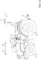
- FIG. 13 is a side view of the working vehicle 1, and FIG. 13 is a plan view of the working vehicle 1.
- the working vehicle 1 is a tractor.
- the working vehicle 1 is not limited to a tractor and may be an agricultural machine (agricultural vehicle) such as a combine or a transplanter, or construction equipment (construction vehicle) such as a loader working machine.
- the front side of an operator seated on an operator seat 10 of the tractor (working vehicle) 1 (a direction of an arrowed line A1 in FIG. 13 ) will be referred to as the front
- the rear side of the operator (a direction of an arrowed line A2 in FIG. 13 ) will be referred to as the rear
- the left side of the operator will be referred to as the left
- the right side of the operator will be referred to as the right.
- the horizontal direction which is a direction orthogonal to the front-to-back direction of the working vehicle 1, is referred to as a vehicle width direction.
- the tractor 1 is provided with a vehicle body 3, a prime mover 4, and a speed-shifter device 5.
- the vehicle body 3 has a traveling device 7, which allows the vehicle body 3 to travel.
- the traveling device 7 is a device having a front wheel 7F and a rear wheel 7R.
- the front wheels 7F may be tire-type or crawler-type.
- the rear wheels 7R also may be tire-type or crawler-type.
- the prime mover 4 is constituted of a diesel engine, an electric motor or the like, the prime mover 4 is the diesel engine in this embodiment.
- the speed-shifter device 5 is capable of switching the propulsion of the traveling device 7 by shifting gears and also of switching the traveling device 7 between the forward traveling and the backward traveling.
- the vehicle body 3 is provided with the operator seat 10.
- the rear portion of the vehicle body 3 is provided with a coupler portion 8 consisting of a three-point linkage mechanism or the like.
- a working device can be attached to and detached from the coupler portion 8. By connecting the working device to the coupler portion 8, the working device can be towed by the vehicle body 3.
- the working device includes a cultivator device for tilling, a fertilizer sprayer device for spraying fertilizer, a pesticide sprayer device for spraying pesticides, a harvester device for harvesting, a mower device for harvesting grasses and the like, a tedder device for diffusing grasses and the like, a raking device for collecting grasses and the like, and a baler device for molding grasses and the like.
- the shuttle portion 5d has a shuttle shaft 12 and a forward/backward switching portion 13.
- the power output from the sub speed-shifter portion 5c is transmitted to the shuttle shaft 12 via gears and other devices.
- the forward/backward switching portion 13 includes, for example, a hydraulic clutch or the like, and switches the direction of rotation of the shuttle shaft 12, that is, the forward movement and backward movement of the tractor 1, by engaging and disengaging the hydraulic clutch.
- the shuttle shaft 12 is connected to a rear wheel differential device 20R.
- the rear wheel differential device 20R rotatably supports the rear axle 21R on which the rear wheel 7R is mounted.
- the tractor 1 is provided with a display device 45.
- the display device 45 is capable of displaying various information about the tractor 1, at least the operation information of the tractor 1.
- the display device 45 is located in front of the operator seat 10.
- the tractor 1 is provided with the steering changeover switch 52.
- the steering changeover switch 52 is a switch that switches the start or end of the automatic steering.
- the steering changeover switch 52 is switchable from the neutral position to up, down, forward, or backward, and issues a start of the automatic steering when switched downward from the neutral position with the setting mode enabled, and issues an end of the automatic steering when switched upward from the neutral position with the setting mode enabled.
- the steering changeover switch 52 also issues to set the current vehicle position to the start point P10 of the reference traveling line L1 when switched from the neutral position to the rear with the setting mode enabled, and the steering changeover switch 52 issues to set the current vehicle position to the end point P11 of the reference traveling line L1 when switched from the neutral position to the front with the setting mode enabled.
- the steering changeover switch 52 serves as both of a reference traveling line setter witch for setting the start position (start point P10) of the reference traveling line L1 and a reference traveling line setter witch for setting the end position (end point P11) of the reference traveling line L1.
- the steering changeover switch 52 may be configured separately from the reference traveling line setter switch and the steering changeover switch 52, which switches the start or end of the automatic steering.
- the tractor 1 is provided with a corrector switch 53.
- the corrector switch 53 is a switch that corrects the vehicle position (latitude and longitude) measured by the positioning device 40. That is, the corrector switch 53 corrects the vehicle position (called the calculated vehicle position) calculated with the satellite signal (position of the positioning satellite, transmission time, correction information, and the like) and the measurement information (acceleration, angular velocity) measured by the inertial measurement device 42.
- the corrector switch 53 includes a push switch or a slide switch, which can be pressed or slidable.
- a case in which the corrector switch 53 is a push switch and a case in which the corrector switch 53 is a slide switch respectively will be described.
- the amount of correction is set based on the amount of operation (displacement amount) of the slide switch.
- the amount of operation of the slide switch (displacement amount) is input to the first controller device 60A, and the first controller device 60A sets (calculates) the correction amount based on the displacement amount.
- the method of increasing the correction amount and the rate of increase is not limited to the values described above.
- the corrector switch 53 has a first corrector portion 53A and a second corrector portion 53B.
- the first corrector portion 53A is the part that commands correction of the vehicle position corresponding to one side, that is, the left side, of the vehicle body 3 in the width direction.
- the second corrector portion 53B is the part that commands correction of the vehicle position corresponding to the other side in the width direction of the vehicle body 3, that is, the right side.
- the first corrector portion 53A and the second corrector portion 53B are on or off switches that automatically return at each operation.
- the switch including the first corrector portion 53A and the switch including the second corrector portion 53B are integrated with the switch including the first corrector portion 53A.
- the switch including the first corrector portion 53A and the switch including the second corrector portion 53B may be disposed apart from each other.
- FIG. 3A each time the first corrector portion 53A is pressed, the amount of correction corresponding to the left side of the vehicle body 3 (the left correction amount) is increased.
- the second corrector portion 53B is pressed, the amount of correction corresponding to the right side of the vehicle body 3 (the right correction amount) increases.
- the first and second corrector portions 53A and 53B include a pinching portion 55 that moves left or right along the longitudinal direction of the long hole.
- the first and second corrector portions 53A and 53B are disposed apart from each other in the width direction.
- the pinching portion 55 when the pinching portion 55 is gradually displaced to the left side from the predetermined reference position, the left correction amount increases in accordance with the displacement amount.
- the pinching portion 55 is gradually displaced to the right side from the predetermined reference position, the right correction amount increases in accordance with the displacement amount.
- FIG. 3B when the pinching portion 55 is gradually displaced to the left side from the predetermined reference position, the left correction amount increases in accordance with the displacement amount.
- FIG. 5A shows the situation when the calculated vehicle position W1 shifts to the right during the automatic steering and straight ahead.
- the tractor 1 when the automatic steering is started and the actual position of the tractor 1 (vehicle body 3) (actual position W2) is the same as the calculated vehicle position W1, and the actual position W2 is the same as the scheduled traveling line L2, the tractor 1 will travel along the scheduled traveling line L2. That is, in the sector P1 where there are no errors in the positioning of the positioning device 40 and the vehicle position (calculated vehicle position W1) detected by the positioning device 40 is the same as the actual position W2, the tractor 1 travels along the scheduled traveling line L2.
- the calculated vehicle position W1 is the same as the corrected vehicle position (corrected vehicle position) W3, corrected by the correction amount.
- the tractor 1 judges that there is a gap between the calculated vehicle position W1 and the scheduled traveling line L2, and steers the tractor 1 to the left so that the offset amount W4 between the calculated vehicle position W1 and the scheduled traveling line L2 is eliminated. Then, the actual position W2 of the tractor 1 shifts to the scheduled traveling line L2 by steering left.
- the operator notices that the tractor 1 has shifted from the scheduled traveling line L2 and steers the second corrector portion 53B at position P21 to increase the right correction amount from zero.
- the right-hand correction is added to the calculated vehicle position W1, and the corrected vehicle position W3 can be made to be substantially the same as the actual position W2.
- the vehicle position of the positioning system 40 can be corrected by the second corrector portion 53B in the direction to eliminate the offset amount W4 that occurred in the vicinity of the position P20.
- the tractor 1 can be steered to the right to bring the actual position W2 of the tractor 1 in line with the scheduled traveling line L2.
- FIG. 5B shows a case in which the calculated vehicle position W1 shifts to the left while the vehicle is moving straight ahead during the automatic steering.
- the tractor 1 travels along the scheduled traveling line L2, as in FIG. 5A . That is, as in FIG. 5A , in the sector P2 where there is no error in the positioning of the positioning device 40, tractor 1 travels along the scheduled traveling line L2.
- the calculated vehicle position W1 and the corrected body position W3 are the same value.
- the column cover 179 is disposed below the steering wheel 30 and covers the outer perimeter of the upper portion of the steering shaft 31.
- the column cover 179 is formed in the shape of a substantially square cylinder and protrudes upward from the attachment surface 178f of the panel cover 178.
- the attachment surface 178f is provided around the perimeter of the column cover 179.
- the setter switch 51 and corrector switch 53 mounted on the attachment surface 178f are located around the perimeter of the column cover 179.
- the setter switch 51 As shown in FIG. 6 , the setter switch 51, the steering changeover switch 52, and the corrector switch 53 are arranged around the steering shaft 31.
- the corrector switch 53 is located on the other side (right side) of the steering shaft 31. More specifically, the corrector switch 53 is disposed on the right side and rearward (diagonally right rearward) of the steering shaft 31. The corrector switch 53 is disposed to the right and rear (diagonally right rear) of the column cover 179 in relation to the column cover 179. The corrector switch 53 is disposed at the right rear portion of the attachment surface 178f in relation to the attachment surface 178f of the panel cover 178. The fact that the corrector switch 53 is disposed at the rear portion of the inclined attachment surface 178f allows for a longer distance between the corrector switch 53 and the steering wheel 30. This can more reliably prevent unintentional operation of the corrector switch 53 and steering wheel 30.
- the automatic steering controller portion 200 rotates the rotational axis of the steering motor 38 so that the steering direction of the tractor 1 is in a left direction. That is, the automatic steering controller portion 200 sets the steering angle in the left direction so that the position deviation is zero.
- the steering angle of the steering device 11 is changed based on the deviation between the vehicle body position and the scheduled traveling line L2.
- the third controller device 60C raises and lowers the coupler portion 8 in response to the operation of an operating member provided around the operator seat 10.
- the first controller device 60A, the second controller device 60B and the third controller device 60C may be integrated.
- the control of the traveling system, the control of the working system, and the calculation of the vehicle position as described above are not limited.
- the tractor 1 (vehicle body 3) can be steered automatically by the controller device 60.
- the second controller device 60B is provided with a steering angle obtainer portion 201 and a steering judgment portion 202, in addition to the automatic steering controller portion 200.
- the steering angle obtainer portion 201 and the steering judgment portion 202 include electrical and electronic circuits in the second controller device 60B, a computer program stored in a CPU or the like.
- the steering angle obtainer portion 201 acquires a plurality of steering angles ⁇ n of the steering device 11 at least during the manual steering.
- the steering angle obtainer portion 201 acquires the steering angle ⁇ n detected by the steering angle detector device 205 on the vehicle body 3 at a predetermined time interval.
- FIG. 9 it is supposed, for example, that the automatic steering is terminated when the steering changeover switch 52 is operated at position P12.
- the steering angle ⁇ in the turning interval T1 is a large value and the steering angle obtainer portion 201 does not acquire the steering angle ⁇ in the turning interval T1 because the steering angle ⁇ is a large value and the steering angle obtainer portion 201 can determine that the tractor 1 is in a turning state.
- the steering angle obtainer portion 201 continuously acquires a plurality of steering angles ⁇ n after position P13 where at least the current steering angle ⁇ M1 is less than or equal to the steering angle of the turn (the turning judgment steering angle ⁇ M2).
- the steering angle obtainer portion 201 acquires a plurality of steering angles ⁇ n within a predetermined judging distance J1 from position P13, for example, or within a predetermined judging time from position P13 by the tractor 1.
- the steering judgment portion 202 finds the standard deviation and the average value of the plurality of steering angles ⁇ n, and permits the start of the automatic steering when all the steering angles ⁇ n are within 3 ⁇ .
- the steering judgment portion 202 does not permit the start of the automatic steering when some of the steering angles ⁇ n are in a region that exceeds 3 ⁇ .
- the steering judgment portion 202 permits the automatic steering when the steering of the steering handle 30 is stable and the vehicle body 3 is considered to be moving in a straight direction, and does not permit the automatic steering when the steering of the steering handle 30 is not stable and the vehicle body 3 is not considered to be moving in a straight direction.
- the display device 45 is capable of displaying that the start of the automatic steering has been determined to be permitted by the steering judgment portion 202. As shown in FIG. 11 , when a predetermined action is performed on the display device 45, the display device 45 displays the driving screen M1.
- the indicator portion 80 is a bar that varies in length according to the magnitude of the prime mover speed.
- the indicator portion 80 is located between the first line 65A and the third line 65C, for example, and has the shortest length at one end (left side) of the first line 65A and the third line 65C when the value of the prime mover speed is the minimum value of zero and has the longest length extending from one end (left side) of the first line 65A and the third line 65C to the other end of the first line 65A and the third line 65C (right side) when the value of the prime mover speed is the maximum value.
- the revolutions display portion 62 includes a numeric display portion 64.
- the numeric display portion 64 displays the number of prime mover revolutions in numbers. For example, the revolutions display portion 62 is located inside the semicircle of the first line 65A and the third line 65C.
- the plurality of icon portions 66 include the first icon portion 66A, the second icon portion 66B, the third icon portion 66C, the fourth icon portion 66D, the fifth icon portion 66E, the sixth icon portion 66F, and the seventh icon portion 66G.
- the driving screen M1 need not have all of the plurality of icon portions 66 (66A, 66B, 66C, 66D, 66E, 66F, and 66G) and is not limited to the embodiments described above.
- the fifth icon portion 66E is displayed when the coupler portion 8 is in the lifted and lowered state.
- the sixth icon portion 66F is displayed when the 4WD is in a state of increasing the speed.
- the seventh icon portion 66G changes color and other colors depending on the receiving sensitivity of the receiving signal of the receiver device 41.
- the correction factor SG1 is a value that is changed according to the slope.
- the reference value SD1 is a constant value set to find the control gain G1.
- the steering angle calculator portion 200b determines the steering angle in the automatic steering based on the orientational deviation between the vehicle orientation and the scheduled traveling line L2 and the control gain G1 determined by the parameter corrector portion 200a.
- the steering angle calculator portion 200b obtains the steering angle by, for example, multiplying the orientational deviation by the control gain G1.
- the steering controller portion 200c controls the steering device 11 based on the steering angle (calculated steering angle) calculated by the steering angle calculator portion 200b. As described above, the steering controller portion 200c controls the steering motor 38 so that when the tractor 1 is located on the left side with respect to the scheduled traveling line L2, the steering angle of the tractor 1 in the right direction is the calculated steering angle. The steering controller portion 200c controls the steering motor 38 so that the steering angle of the tractor 1 in the left direction of the tractor 1 is the arithmetic steering angle when the tractor 1 is located on the right side with respect to the scheduled traveling line L2, as described above.
- FIG. 15A , FIG. 15B , FIG. 16A , and FIG. 16B the explanation was given for the width direction with respect to the vehicle body 3.
- the same effect can be achieved when the vehicle body 3 is inclined with respect to the direction of traveling of the vehicle body 3, whether it is uphill or downhill.
- the control gain G1 is increased by the parameter corrector portion 200a, so that the steering angle ⁇ 3 in response to the pitch angle is greater than the steering angle ⁇ 1 set without correction. This makes it easier to change the direction of traveling of the vehicle body 3 when the vehicle body 3 is moving up the field compared to the changing on the level ground.
- the control gain G1 is reduced by the parameter corrector portion 200a, so that the steering angle ⁇ 2 in response to the pitch angle is smaller than the steering angle ⁇ 1 set without correction.
- the working vehicle 1 includes the steering device 11 to change the orientation of the vehicle body 3, the inclination detector device to detect the inclination of the vehicle body 3, a steering angle calculator portion 200b to calculate the steering angle of the steering device 11 to reduce the deviation based on the deviation between the planned line L2 and the vehicle body 3 and predetermined parameters, and the parameter corrector portion 200a to change a parameter to be applied to the steering angle calculator portion 200b based on the inclination of the vehicle body 3 detected by the inclination detector device.
- the parameter to be applied to the steering angle calculator portion 200b is changed when the vehicle body 3 is inclined, so that the steering behavior of the vehicle body 3 can be changed in response to the inclination of the vehicle body 3.
- the vehicle body 3 is traveling on a sloping ground, it can easily be made to travel along the scheduled traveling line L2.
- the parameter corrector portion 200a changes the parameter when the inclination of the vehicle body 3 detected by the inclination detector device is greater than or equal to a predetermined threshold value.
- the parameter is corrected under circumstances where the leaning of the vehicle body 3 affects the steering, that is, when the leaning of the vehicle body 3 is greater than or equal to the threshold, so that the vehicle body 3 can be driven along the scheduled traveling line L2 both on flat ground with little leaning and on sloping ground with large leaning.
- the parameter corrector portion 200a corrects the parameter in a direction in which the steering angle increases when the inclination of the vehicle body 3 obtained from the inclination detector device indicates an upward direction, and corrects the parameter in a direction in which the steering angle decreases when the inclination of the vehicle body 3 indicates a downward direction.
- the parameter is corrected to increase the steering angle by correcting the parameter, thus eliminating the difficulty of the vehicle body 3 in turning due to the influence of the hill climbing.
- the parameter correction reduces the steering angle so that the vehicle body 3 does not turn too much due to the effect of the hill descending.
- the parameter corrector portion 200a changes the control gain for calculating the steering angle of the steering device 11 as a parameter. According to this configuration, the steering angle can be easily obtained by changing the control gain SG1.
- the second controller device 60B makes a determination (judgment) whether or not to permit the automatic steering at least prior to the automatic steering, that is, based on the vehicle orientation F1 of the tractor 1 (vehicle body 3) and the orientation of the reference traveling line L1 (line orientation) F2 in the manual steering.
- the second controller device 60B is provided with an orientation judgment portion (orientation judgment circuit) 207.
- the orientation judgment portion 207 includes an electrical and electronic circuit in the second controller device 60B, a computer program stored in a CPU or the like.
- the orientation judgment portion 207 permits the automatic steering when the orientational difference ⁇ F between the vehicle orientation F1 and the line orientation F2 is within the judgment range G1, and does not permit the automatic steering when it is out of the judgment range G1.
- FIG. 18 shows the relation between the orientational difference ⁇ F and the judgment range G1.
- the judgment range G1 is a range shown as negative on one side (left side) and positive on the other side (right side), centered on a reference traveling line 210 (reference traveling line 210) where the vehicle orientation F1 and the line orientation F2 coincide (the reference traveling line 210 where the orientational difference ⁇ F is zero).
- the lower limit Gmin of the judgment range G1 is on the negative side
- the upper limit Gmax is on the positive side.
- the positive and negative in the judgment range G1 are set for convenience and are not limited to the examples described above.
- the lower limit Gmin and the upper limit Gmax of the judgment range G1 are predetermined values, and when the lower limit Gmin and the upper limit Gmax are considered in absolute values, they are the same values.
- the orientation judgment portion 207 permits the automatic steering, and when the orientational difference ⁇ F is out of the judgment range G1, the automatic steering is not permitted.
- the second controller device 60B determines whether or not to permit the automatic steering based on the orientational difference ⁇ F and the judgment range G1.
- the second controller portion 60B changes the judgment range G1 used for the automatic steering according to the inclination of the vehicle body 3whnf the tractor 1 (vehicle body 3) is traveling at an angle.
- the inclination of the vehicle body 3 is detected by an inclination detector device provided in the tractor 1 (vehicle body 3).
- the inclination detector device is an inertial measurement device 42 having, for example, an acceleration sensor to detect acceleration, a gyroscope to detect angular velocity, and the like, which can detect the tractor 1 (vehicle body 3).
- the inclination detector device may be a device including a plurality of positioning devices 40 (for example, a GPS compass, and the like), or it may be any other device.
- the orientation judgment portion 207 sets the judgment range G1 to the standard range ST1 and determines whether the automatic steering is permitted or not based on the standard range ST1.
- the second controller device 60B makes the lower limit Gmin of the judgment range G1 greater than the lower limit Gmin indicated in the standard range ST1. That is, in viewing the reference traveling line L1 from the tractor 1, the lower limit Gmin of the judgment range G1 is increased when the reference traveling line L1 is high and the tractor 1 side is low falling to the right. In this case, the orientation judgment portion 207 determines whether or not to permit the automatic steering based on the judgment range G1 in which the lower limit Gmin is increased.
- the lower limit Gmin corresponding to the higher side (one side) of the tractor 1 is increased.
- the upper limit Gmax opposite to the lower limit Gmin in the judgment range Gmin is less than the upper limit Gmax of the standard range ST1. In other words, in cases where tractor 1 is inclined downward to the right, the upper value Gmax corresponding to the lower side (other side) of the tractor 1 is reduced.
- the second controller device 60B makes the upper limit Gmax of the judgment range G1 greater than the upper limit Gmax indicated in the standard range ST1. That is, in viewing the reference traveling line L1 from the tractor 1, the upper limit value Gmax of the judgment range G1 is increased when the reference traveling line L1 is high and the tractor 1 side is low falling to the left.
- the orientation judgment portion 207 determines whether the automatic steering is permitted or not based on the judgment range G1 in which the upper limit value Gmax is increased.
- the second controller device 60B In changing the lower limit Gmin and upper limit Gmax of the judgment range G1, the second controller device 60B increases the lower limit Gmin and the upper limit Gmax according to the degree of the slope (inclination magnitude) of the vehicle body of the tractor 1 in the width direction of the vehicle body 3 (roll angle of the vehicle body 3). That is, the second controller device 60B increases the lower limit Gmin and upper limit Gmax with respect to the standard range ST1 when the inclination amount is large, and decreases the lower limit Gmin and upper limit Gmax with respect to the standard range ST1 when the inclination amount is small.
- the automatic steering controller portion 200 controls the steering device 11 as described above when the start of the automatic steering is switched by the steering changeover switch 52 when the start of the automatic steering is determined to be permitted by the orientation judgment portion 207.
- the traveling orientation of the working vehicle 1 is an uphill direction (the vehicle orientation is oriented in the uphill direction) or a case where the traveling orientation of the working vehicle 1 is a down-hill direction (the vehicle orientation is oriented in the down-hill direction)
- the traveling orientation of the working vehicle 1 is a down-hill direction (the vehicle orientation is oriented in the down-hill direction)
- the traveling orientation can be stable in switching the steering from the manual steering to the automatic steering even on the slope.
- the controller device 60B changes the lower limit Gmin of the judgment range G1 in accordance with the inclination of the vehicle body 3, when the vehicle body 3 is inclined such that one side of the vehicle body 3 in the width direction is higher than the other side in the width direction.
- the controller device 60B also changes the upper limit Gmax of the judgment range G1 in accordance with the inclination of the vehicle body 3 when the vehicle body 3 is inclined such that one side of the vehicle body 3 in the width direction is lower than the other side in the width direction.
- the display device 45 is capable of displaying the line orientation F2 and vehicle orientation F1 of the reference traveling line L1. As shown in FIG. 20 , when a predetermined action is performed on the display device 45, the display device 45 displays an orientation screen M2.
- the orientation screen M2 includes a line orientation display portion 130 and a vehicle orientation display portion 140.
- the line orientation display portion 130 is configured to indicate the line orientation F2 of the reference traveling line L1 and includes the line display portion 130a and the mark portion 130b.
- the line display portion 130a representing the reference traveling line L1 itself with a line diagram and the like, and extends from the bottom to the top on a field 133 set in the orientation screen M2.
- the mark portion 130b indicates a direction of the reference traveling line L1, for example, is arranged on the upper portion of the end portion 131 of the line display portion 130a in the field 133. In the mark portion 130b, the vertex 132 of the triangle points to the end portion 131 of the line display portion 130a.
- the orientation indicator portion 141 includes, for example, a graphic such as an arrow, and the orientation indicator portion 141 moves to one side or the other of the line display portion 130a with respect to the origin O1 set on the line display portion 130a.
- the vehicle orientation display portion 140 also includes the vehicle body display portion 142, which shows the tractor 1 (vehicle body 3) in graphic form.
- the vehicle body display portion 142 like the orientation indicator portion 141, changes position (display position) according to the orientation around the origin O1.
- the orientation indicator portion 141 is arranged in front of the vehicle body display portion 142 (on the front of the tractor 1), and the vehicle body display portion 142 and the orientation indicator portion 141 simultaneously oscillate according to the vehicle orientation F1.
- the tip portion 141a of the orientation indicator portion 141 and the end portion 131 of the mark portion 130b are opposite each other.
- the tip portion 141a of the orientation indicator portion 141 is located to the left of the line display portion 130a.
- FIG. 21C when the vehicle orientation F1 is displaced to the right with respect to the line orientation F2, the tip portion 141a of the orientation indicator portion 141 is located to the right of the line display portion 130a.
- the operator can determine the extent to which the vehicle orientation F1 deviates from the line orientation F2.
- an orientation scale portion 145 may be displayed on the orientation screen M2.
- the orientation scale portion 145 is a scale in which the line orientation F2 of the reference traveling line L1 is the reference point O2, and the orientational difference ⁇ F (a value indicating the orientation) increases or decreases according to the distance from the reference point O2. That is, the orientation scale portion 145 includes a semicircular shape with a scale line 145a assigned to the orientational difference ⁇ F at predetermined intervals along the circumference of the semicircular shape. At the reference point O2 of the orientation scale portion 145, the end portion 131 of the mark portion 130b is pointed to. In addition, as shown in FIG. 23 , the orientation scale portion 145 shows a judgment range G1.
- the plurality of scale lines 145a on the orientation scale portion 145 are colored with at least two colors separately, and the plurality of scale lines 145a near the reference point O2 are colored with a color indicating that the value is within the judgment range G1 (a color within the range), and the plurality of scale lines 145a at a distance from the reference point O2 are colored with a value out of the judgment range G1 (a color out of the range) to indicate that a value is out of the judgment range G1.
- the judgment range G1 is changed in accordance with the inclination of the vehicle body 3
- the plurality of scale lines 145a are colored to correspond to in-range and out-of-range of the changed judgment range G1.
- the orientation indicator portion 141 is arranged inside the orientation scale portion 145 and points the vehicle orientation F1 to the orientation scale portion 145.
- the orientation indicator portion 141 has a different display configuration when the orientational difference ⁇ F between the line orientation F2 and the vehicle orientation F1 is within a predetermined range (within the judgment range G1) or when the orientational difference ⁇ F is out of the predetermined range (outside the judgment range G1).
- the orientation indicator portion 141 is colored the same color as the in-range color of the orientation scale portion 145 when the orientational difference ⁇ F is within the predetermined range (within the judgment range G1).
- the orientation indicator portion 141 is colored the same color as the color out of range of the orientation scale portion 145 when the orientational difference ⁇ F is out of the predetermined range (out of the judgment range G1).
- the display device 45 displays, on the orientation screen M2, a steering wheel display 68 showing a graphic of the steering wheel 30, and displays a graphic 143 indicating that the automatic steering can be started.
- the working vehicle 1 includes the steering handle 30, the traveling body 3 configured to travel in either in the manual steering by the steering handle 30 or in the automatic steering of the steering handle 30 based on the reference traveling line L1, the line orientation display portion 130 indicating the orientation F2 of the reference traveling line L1, and the display device 45 having the vehicle orientation display portion 140 indicating the orientation F1 of the vehicle body 3.
- the display device 45 allows the user to easily determine which orientation the working vehicle 1 (vehicle body 3) is facing with respect to the orientation F2 of the reference traveling line L1.
- the line orientation display portion 130 includes the line display portion 130a which indicates the reference traveling line L1, and the mark portion 130b which indicates the orientation F2 of the reference traveling line L1. According to this configuration, even when the operator is not able to know exactly what orientation the orientation F2 of the reference traveling line L1 is in a work field or other work area, the orientation F2 of the reference traveling line L1 can be easily ascertained by looking at the line display portion 130a and the mark portion 130b displayed on the display device 45.
- the vehicle orientation display portion 140 includes the orientation indicator portion 141 which points to the orientation F1 of the vehicle body 3, and the vehicle body display portion 142 which shows the vehicle body 3 whose display position changes according to the orientation F1 of the vehicle body 3. Accordingly, even when the operator is not able to accurately determine the orientation F1 of the vehicle body 3 in the work field, the orientation F1 of the vehicle body 3 can be easily ascertained by looking at the orientation indicator portion 141 and the vehicle body display 142 displayed on the display device 45.
- the display device 45 has an orientation scale portion 145 which has the orientation F2 of the reference traveling line L1 as the reference point and whose value indicating the orientation increases or decreases depending on the distance from the reference point.
- the line orientation display portion 130 includes, in the reference point, the mark portion 130b indicating the orientation of the reference traveling line. According to this configuration, when looking at the scale portion 145, an operator can easily know which direction the orientation F2 of the reference traveling line L1 is with respect to the vehicle body 3.
- the vehicle orientation display portion 140 includes the orientation indicator portion 141 that points to the orientation F1 of the vehicle body 3, and the orientation indicator portion 141 points the orientation F1 of the vehicle body 3 to the orientation scale portion 145. According to this configuration, the extent to which the orientation F1 of the vehicle body 3 is out of alignment with the reference traveling line L1 can be easily ascertained by looking at the orientation indicator portion 141 indicated on the orientation scale portion 145.
- the vehicle orientation display 140 has different display formats alternately displayed when the orientational difference ⁇ F between the orientation F2 of the reference traveling line L1 and the orientation F1 of the vehicle body 3 is within a predetermined range and when the orientational difference ⁇ F is out of the predetermined range. This makes it easy for the operator to know whether or not the difference in the orientation ⁇ F is within the predetermined range.
- the working vehicle includes the controller device 60B configured to permit the automatic steering when the orientation difference ⁇ F between the orientation F2 of the reference traveling line L1 and the orientation F1 of the vehicle body 3 is within a predetermined range. This makes it easy to switch the steering from the manual steering to the automatic steering.
- the configurations of the third embodiment are configured in the same manner as in the first embodiment.
Landscapes
- Engineering & Computer Science (AREA)
- Mechanical Engineering (AREA)
- Transportation (AREA)
- Chemical & Material Sciences (AREA)
- Combustion & Propulsion (AREA)
- Automation & Control Theory (AREA)
- Human Computer Interaction (AREA)
- Life Sciences & Earth Sciences (AREA)
- Physics & Mathematics (AREA)
- Soil Sciences (AREA)
- Environmental Sciences (AREA)
- Aviation & Aerospace Engineering (AREA)
- Radar, Positioning & Navigation (AREA)
- Remote Sensing (AREA)
- General Physics & Mathematics (AREA)
- Mathematical Physics (AREA)
- Guiding Agricultural Machines (AREA)
- Steering Control In Accordance With Driving Conditions (AREA)
Description
- The present invention relates to a working vehicle.
- Document
JP 2017-123803 JP 2017-123803 - A steering system is known from the Document
DE 10 198 08 100 A1 . A work vehicle and an automatic steering system are known from the DocumentJP 2016-024541 A - In the agricultural working machine of
JP 2017-123803 - In the automatic traveling, it is desirable that the agricultural working machine is traveling in a straight line just before the start of automatic traveling, in order to control the agricultural working machine to travel along a reference traveling line. When starting the automatic traveling under a state where the agricultural working machine does not travel in a straight line, the initial behavior of the agricultural working machine may be unstable.
- In addition, in the patent, it is difficult to drive the agricultural working machine along a set traveling line set on a slope. That is, it is difficult to make the agricultural working machine travel along the set traveling line under a state where the agricultural working machine is inclined.
- In addition, since the agricultural working machine travels along the reference traveling line in the automatic traveling, a traveling orientation of the agricultural working machine is often the same as an orientation of the reference traveling line just before the automatic operation, and when the orientation of the agricultural working machine and the direction of the reference traveling line are greatly out of line, the initial behavior of the agricultural working machine may be unstable. In particular, under a state where the agricultural working machine is traveling on a slope, the automatic steering is required to be adapted to the slope because the orientation of the agricultural working machine is likely to change easily.
- In view of the above problems, the present invention is intended to provide a working vehicle configured to be driven stably when switching from the manual steering to the automatic steering.
- In addition, the present invention is intended to provide a working vehicle configured to be easily driven along a scheduled traveling line.
- In addition, the present invention is intended to provide a working vehicle configured to perform the automatic steering stably.
- Technical means of the present invention for solving this technical problem is characterized by the following points.
- A working vehicle according to an aspect of the present invention, includes: a steering device having a steering handle; a vehicle body to travel with either manual steering by the steering handle or automatic steering of the steering handle based on a reference traveling line; a positioning device configured to detect an orientation of the vehicle body; and a display device including: a line orientation display portion to indicate an orientation of the reference line; a vehicle orientation display portion to indicate the orientation of the vehicle body and an orientation scale portion having a reference point that coincides with the orientation of the reference traveling line and being configured to increase and decrease a value indicating the orientation of the reference traveling line based on a distance from the reference point; and a controller device configured to permit the automatic steering by the steering device when an orientational difference which is a difference between the orientation of the vehicle body detected by the positioning device and the orientation of the reference traveling line is within a judgment range and to perform the automatic steering by the steering device when permitting the automatic steering, the working vehicle being characterized by comprising: an inclination detector device configured to detect an inclination of the vehicle body in a width direction, wherein the orientation scale portion is configured to show the judgment range, the controller device is configured to change the judgment range in accordance with the inclination of the vehicle body in the width direction detected by the inclination detector device, and the orientation scale portion is configured to, when the judgment range is changed in accordance with the inclination of the vehicle body in the width direction, show the changed judgment range.
- In some embodiments, the controller device is configured to set a standard range centered on a reference line and having a lower limit and an upper limit which are on opposite sides of the reference line and which have the same absolute value, the reference line being a line on which the orientation of the vehicle body and the orientation of the reference traveling line coincide with each other, set the judgment range to the standard range when the inclination of the vehicle body in the width direction is zero, determine whether or not to permit the automatic steering based on the standard range, and cause the display device to display the judgment range set to the standard range. The controller device is further configured to, when the vehicle body is in a first inclined state in which one of opposite sides of the vehicle body in the width direction is higher than the other, change the judgment range to obtain a changed judgment range by increasing the absolute value of the lower limit of the judgment range such that the lower limit has an absolute value greater than that of the lower limit of the standard range, determine whether or not to permit the automatic steering based on the changed judgment range, and cause the display device to display the changed judgment range. The controller device is further configured to, when the vehicle body is in a second inclined state in which the one of the opposite sides of the vehicle body in the width direction is lower than the other, change the judgment range to obtain a changed judgment range by increasing the absolute value of the upper limit of the judgment range such that the upper limit has an absolute value greater than that of the upper limit of the standard range, determine whether or not to permit the automatic steering based on the changed judgment range, and cause the display device to display the changed judgment range.
- In some embodiments, the controller device is configured to, when the vehicle body is in the first inclined state, change the judgment range to obtain a changed judgment range by reducing the absolute value of the upper limit of the judgment range such that the upper limit has an absolute value less than that of the upper limit of the standard range, determine whether or not to permit the automatic steering based on the changed judgment range, and cause the display device to display the changed judgment range. The controller device is further configured to, when the vehicle body is in the second inclined state, change the judgment range to obtain a changed judgment range by reducing the absolute value of the lower limit of the judgment range such that the lower limit has an absolute value less than that of the lower limit of the standard range, determine whether or not to permit the automatic steering based on the changed judgment range, and cause the display device to display the changed judgment range.
- The line orientation display portion includes: a line display portion to indicate the reference traveling line; and a mark portion to indicate an orientation of the reference traveling line at the reference point.
- The vehicle orientation display portion includes: an orientation pointer portion to point the orientation of the vehicle body; and a vehicle display portion to display the vehicle body whose display position is changed based on the orientation of the vehicle body.
- The vehicle orientation display portion includes an orientation pointer portion to point the orientation of the vehicle body, and the orientation pointer points the orientation of the vehicle body on the orientation scale portion.
- The vehicle orientation display portion has a display format provided when the orientational difference between the orientation of the reference traveling line and the orientation of the vehicle body is within the judgement range and another display format provided when the orientational difference is out of the judgement range.
- According to the present invention, a traveling vehicle can be driven stably when switching from manual steering to automatic steering.
- In addition, according to the present invention, it is possible to perform automatic steering stably even when a vehicle body is tilted because of some reason.
- In addition, according to the present invention, automatic steering can be performed stably.
-
- FIG. 1
- is a view illustrating a control block diagram and configuration of a tractor.
- FIG. 2
- is an explanation view explaining automatic steering.
- FIG. 3A
- is an explanation view explaining a correction amount in a push switch.
- FIG. 3B
- is an explanation view explaining a correction amount in a sliding switch.
- FIG. 4A
- is a view illustrating a first corrector portion and a second corrector portion in a push switch.
- FIG. 4B
- is a view illustrating a first corrector portion and a second corrector portion in a sliding switch.
- FIG. 5A
- is a view illustrating a state where a calculated vehicle position is offset rightward during straight traveling in automatic steering.
- FIG. 5B
- is a view illustrating a state where a calculated vehicle position is offset leftward during straight traveling in automatic steering.
- FIG. 6
- is a view of a cover provided in front of an operator seat, which is seen from an operator seat side.
- FIG. 7
- is an explanation view explaining controls in automatic steering.
- FIG. 8
- is an explanation view of conditions of automatic steering.
- FIG. 9
- is a view of obtaining a plurality of steering angles θn.
- FIG. 10A
- is a view illustrating an example of distribution where a plurality of steering angles θn are less dispersed.
- FIG. 10B
- is a view illustrating an example of distribution where a plurality of steering angles θn are much dispersed.
- FIG. 11
- is a view illustrating an example of a driving screen.
- FIG. 12
- is an explanation view explaining a tractor traveling on a slope.
- FIG. 13
- is a whole view of a tractor.
- FIG. 14
- is a view illustrating a working vehicle traveling on a slope.
- FIG. 15A
- is a view illustrating a state where a tractor is steered to a downward direction without correcting a parameter (a control gain).
- FIG. 15B
- is a view illustrating a state where a tractor is steered to a downward direction with a parameter (a control gain) corrected.
- FIG. 16A
- is a view illustrating a state where a tractor is steered to an upward direction without correcting a parameter (a control gain).
- FIG. 16B
- is a view illustrating a state where a tractor is steered to an upward direction with a parameter (a control gain) corrected.
- FIG. 17
- is an explanation view of conditions of automatic steering.
- FIG. 18
- is a view illustrating a relation between an orientational difference ΔF and a judgment range G1.
- FIG. 19A
- is an explanation view explaining an example of changing a lower limit value of a judgment range G1 in a case where a tractor inclines downward right.
- FIG. 19B
- is an explanation view explaining an example of changing an upper limit value of a judgment range G1 in a case where a tractor inclines downward left.
- FIG. 19C
- is an explanation view explaining an example of changing an upper limit value of a judgment range G1 in a case where a tractor inclines downward right.
- FIG. 19D
- is an explanation view explaining an example of changing a lower limit value of a judgment range G1 in a case where a tractor inclines downward left.
- FIG. 20
- is a view illustrating an example of an orientation screen M2.
- FIG. 21A
- is a view illustrating an orientation screen M2 in a case where a vehicle orientation F1 coincides with a line orientation F2.
- FIG. 21B
- is a view illustrating an orientation screen M2 in a case where a vehicle orientation F1 slightly offsets leftward with respect to a line orientation F2.
- FIG. 21C
- is a view illustrating an orientation screen M2 in a case where a vehicle orientation F1 slightly offsets rightward with respect to a line orientation F2.
- FIG. 22A
- is a view illustrating an orientation screen M2 in a case where a vehicle orientation F1 widely offsets leftward with respect to a line orientation F2.
- FIG. 22B
- is a view illustrating an orientation screen M2 in a case where a vehicle orientation F1 widely offsets rightward with respect to a line orientation F2.
- FIG. 23
- is a view illustrating details of a scale portion.
- Hereinafter, an embodiment of the present invention will be described with appropriate reference to the drawings.
-
FIG. 1 to FIG. 13 illustrate a first embodiment. -
FIG. 13 is a side view of the workingvehicle 1, andFIG. 13 is a plan view of the workingvehicle 1. In this embodiment, the workingvehicle 1 is a tractor. However, the workingvehicle 1 is not limited to a tractor and may be an agricultural machine (agricultural vehicle) such as a combine or a transplanter, or construction equipment (construction vehicle) such as a loader working machine. - In the following description, the front side of an operator seated on an
operator seat 10 of the tractor (working vehicle) 1 (a direction of an arrowed line A1 inFIG. 13 ) will be referred to as the front, the rear side of the operator (a direction of an arrowed line A2 inFIG. 13 ) will be referred to as the rear, the left side of the operator will be referred to as the left, and the right side of the operator will be referred to as the right. The horizontal direction, which is a direction orthogonal to the front-to-back direction of the workingvehicle 1, is referred to as a vehicle width direction. - As shown in
FIG. 13 , thetractor 1 is provided with avehicle body 3, aprime mover 4, and a speed-shifter device 5. Thevehicle body 3 has a travelingdevice 7, which allows thevehicle body 3 to travel. The travelingdevice 7 is a device having afront wheel 7F and arear wheel 7R. Thefront wheels 7F may be tire-type or crawler-type. Therear wheels 7R also may be tire-type or crawler-type. - The
prime mover 4 is constituted of a diesel engine, an electric motor or the like, theprime mover 4 is the diesel engine in this embodiment. The speed-shifter device 5 is capable of switching the propulsion of the travelingdevice 7 by shifting gears and also of switching the travelingdevice 7 between the forward traveling and the backward traveling. Thevehicle body 3 is provided with theoperator seat 10. - The rear portion of the
vehicle body 3 is provided with acoupler portion 8 consisting of a three-point linkage mechanism or the like. A working device can be attached to and detached from thecoupler portion 8. By connecting the working device to thecoupler portion 8, the working device can be towed by thevehicle body 3. The working device includes a cultivator device for tilling, a fertilizer sprayer device for spraying fertilizer, a pesticide sprayer device for spraying pesticides, a harvester device for harvesting, a mower device for harvesting grasses and the like, a tedder device for diffusing grasses and the like, a raking device for collecting grasses and the like, and a baler device for molding grasses and the like. - As shown in
FIG. 1 , the speed-shifter device 5 is provided with a main shaft (propulsion shaft) 5a, a main speed-shifter portion 5b, a sub speed-shifter portion 5c, ashuttle portion 5d, aPTO power transmission 5e, and a front speed-shifter portion 5f. Thepropulsion shaft 5a is rotatably supported in a housing case (transmission case) of the speed-shifter device 5, and power from the crankshaft of theprime mover 4 is transmitted to thepropulsion shaft 5a. The main speed-shifter portion 5b has a plurality of gears and a shifter for changing the engagement of the gears. The main speed-shifter portion 5b changes the rotation input from thepropulsion shaft 5a and outputs (shifts the speed) by changing the connection (engagement) of the plurality of gears with the shifter accordingly. - The sub speed-
shifter portion 5c, like the main speed-shifter portion 5b, has a plurality of gears and a shifter for changing the engagement of the gears. By changing the connection (engagement) of the plurality of gears with the shifter as appropriate, the sub speed-shifter portion 5c changes the rotation input from the main speed-shifter portion 5b and outputs the changed rotation (speed shifting). - The
shuttle portion 5d has a shuttle shaft 12 and a forward/backward switching portion 13. The power output from the sub speed-shifter portion 5c is transmitted to the shuttle shaft 12 via gears and other devices. The forward/backward switching portion 13 includes, for example, a hydraulic clutch or the like, and switches the direction of rotation of the shuttle shaft 12, that is, the forward movement and backward movement of thetractor 1, by engaging and disengaging the hydraulic clutch. The shuttle shaft 12 is connected to a rear wheeldifferential device 20R. The rear wheeldifferential device 20R rotatably supports therear axle 21R on which therear wheel 7R is mounted. - The
PTO power transmission 5e has aPTO propulsion shaft 14 and a PTO clutch 15. ThePTO propulsion shaft 14 is rotatably supported, and the power from thepropulsion shaft 5a can be transferred from thepropulsion shaft 5a. ThePTO propulsion shaft 14 is connected to the PTO shaft 16 via the gears and the like. The PTO clutch 15 includes, for example, a hydraulic clutch and the like, and is switched between a state where the power of thepropulsion shaft 5a is transferred to thePTO propulsion shaft 14 and a state where the power of thepropulsion shaft 5a is not transferred to thePTO propulsion shaft 14. - The front speed-
shifter device 5f has a first clutch 17 and asecond clutch 18. The first clutch 17 and the second clutch are capable of transmitting power from thepropulsion shaft 5a, for example, the power of the shuttle shaft 12 is transmitted via the gears and the transmission shaft. The power from the first clutch 17 and the second clutch 18 can be transmitted to thefront axle 21F via thefront transmission shaft 22. In particular, thefront transmission shaft 22 is connected to a front wheeldifferential device 20F, which rotatably supports thefront axle 21F on which thefront wheels 7F are mounted. - The first clutch 17 and the second clutch 18 include a hydraulic clutch or the like. A fluid line is connected to the first clutch 17, and the fluid line is connected to a
first actuator valve 25, to which the hydraulic fluid discharged from the hydraulic pump is supplied. The first clutch 17 is switched between an engaged state and a disengaged state depending on the degree of opening of thefirst actuator valve 25. A fluid line is connected to the second clutch 18, and the fluid line is connected to asecond actuator valve 26. The second clutch 18 is switched between an engaged state and a disengaged state depending on the degree of opening of thesecond actuator valve 26. The first andsecond actuation valves - When the first clutch 17 is disengaged and the second clutch 18 is engaged, the power of the shuttle shaft 12 is transmitted to the
front wheels 7F through thesecond clutch 18. This results in four-wheel driving (4WD) in which the front and rear wheels are driven by the power and the rotation speed of the front and rear wheels is substantially the same (4WD constant speed state). On the other hand, when the first clutch 17 is engaged and the second clutch 18 is disengaged, four-wheel driving is provided and the rotation speed of the front wheel becomes higher than that of the rear wheel (4WD constant speed state). When the first andsecond clutches front wheels 7F, and thus the vehicle becomes two-wheel drive (2WD) with the rear wheels driven by power. - The
tractor 1 is provided with apositioning device 40. Thepositioning device 40 is capable of detecting its own position (positioning information including latitude and longitude) by a satellite positioning system (positioning satellite) such as D-GPS, GPS, GLONASS, HOKUTO, GALILEO, MICHIBIKI, and the like. That is, thepositioning device 40 receives satellite signals transmitted by the positioning satellite (such as the position of the positioning satellite, transmission time, correction information, and the like) and detects its position (for example, latitude and longitude) based on the satellite signals. Thepositioning device 40 has areceiver device 41 and an inertial measurement device (IMU: Inertial Measurement Unit) 42. Thereceiver device 41 has an antenna or the like and receives satellite signals transmitted from a positioning satellite, and is attached to thevehicle body 3 separately from theinertial measurement unit 42. In this embodiment, thereceiver device 41 is attached to a ROPS provided to thevehicle body 3. The attachment location of thereceiver device 41 is not limited to that of this embodiment. - The
inertial measurement device 42 has an acceleration sensor to detect acceleration, a gyroscope to detect angular velocity, and so forth. Thevehicle body 3, for example, is installed below theoperator seat 10, and the roll angle, pitch angle, yaw angle, and the like of thevehicle body 3 can be detected by theinertial measurement device 42. - As shown in
FIG. 1 , thetractor 1 is provided with asteering device 11. Thesteering device 11 is a device capable of performing manual steering to steer the body of thevehicle body 3 by the operator and automatic steering to steer the body of thevehicle body 3 automatically without the operator's operation. - The
steering device 11 has a steering handle (steering wheel) 30 and a steering shaft (rotating shaft) 31 that rotatably supports thesteering handle 30. Thesteering device 11 also has an assist mechanism (power steering device) 32. Theassist mechanism 32 assists the rotation of the steering shaft 31 (steering handle 30) by hydraulic or other means. Theassist mechanism 32 includes ahydraulic pump 33, acontrol valve 34 to which the hydraulic fluid discharged from thehydraulic pump 33 is supplied, and asteering cylinder 35 operated by thecontrol valve 34. Thecontrol valve 34 is, for example, a three-position switching valve that can be switched by movement of a spool or the like, and is switched in response to the steering direction (direction of rotation) of the steeringshaft 31. Thesteering cylinder 35 is connected to an arm (knuckle arm) 36 that changes the direction of thefront wheels 7F. - Thus, when the operator grasps the
steering wheel 30 and operates thesteering wheel 30 in one direction or the other, the switching position and opening degree of thecontrol valve 34 will be switched according to the direction of rotation of thesteering wheel 30, and thesteering cylinder 35 will stretch and shorten to the left or right according to the switching position and opening degree of thecontrol valve 34. The direction of steering of thefront wheels 7F can be changed by thesteering wheel 30. In other words, thevehicle body 3 can change the direction of travel to the left or right by manual steering of thesteering handle 30. - Next, automatic steering will be explained.
- As shown in
FIG. 2 , when automatic steering is performed, first, a reference traveling line L1 is set before automatic steering is performed. After the reference traveling line L1 is set, the automatic steering can be performed by setting the scheduled traveling line L2, which is parallel to the reference traveling line L1. The automatic steering automatically steers the tractor 1 (vehicle body 3) in the direction of traveling so that the vehicle position measured by thepositioning device 40 and the scheduled traveling line L2 coincide. - In particular, when the tractor 1 (vehicle body 3) is moved to a predetermined position in the field prior to the automatic steering (S1), and at the predetermined position, the operator operates the
steering changeover switch 52 provided on the tractor 1 (step S2), the vehicle position measured by thepositioning device 40 is set at the start point P10 of the reference traveling line L1 (step S3). When the tractor 1 (vehicle body 3) is moved from the start point P10 of the reference traveling line L1 (step S4) and the operator operates thesteering changeover switch 52 at the predetermined position (step S5), the vehicle position measured by thepositioning device 40 is set at the end point P11 of the reference traveling line L1 (step S6). Thus, a straight line connecting the start point P10 and the end point P11 is set as the reference traveling line L1. - After setting the reference traveling line L1 (after step S6), for example, when the tractor 1 (vehicle body 3) is moved to a different location than where the reference traveling line L1 was set (step S7) and the operator operates the steering changeover switch 52 (step S8), the scheduled traveling line L2, which is a straight line parallel to the reference traveling line L1, is set (step S9). After the scheduled traveling line L2 is set, the automatic steering is started and the direction of traveling of the tractor 1 (vehicle body 3) is changed so that it follows the scheduled traveling line L2. For example, when the current vehicle position is on the left side of the scheduled traveling line L2, the
front wheel 7F is steered to the right, and when the current vehicle position is on the right side of the scheduled traveling line L2, thefront wheel 7F is steered to the left. During the automatic steering, the travel speed (vehicle speed) of the tractor 1 (vehicle body 3) can be changed by the operator manually changing the amount of operation of the gas pedal members (accelerator pedal and gas pedal lever) provided in thetractor 1, or by changing the gear shift of the speed shifter (transmission). - After the start of the automatic steering, the automatic steering can be terminated when the operator operates the
steering changeover switch 52 at any point. That is, the end point of the scheduled traveling line L2 can be set by the end of the automatic steering by operating thesteering changeover switch 52. In other words, the length of the end point of the scheduled traveling line L2 can be set longer or shorter than the reference traveling line L1. In other words, the scheduled traveling line L2 is not associated with the length of the reference traveling line L1, and the scheduled traveling line L2 allows the vehicle to travel a longer distance than the length of the reference traveling line L1 under the automatic steering. - As shown in
FIG. 1 , thesteering device 11 has anautomatic steering mechanism 37. Theautomatic steering mechanism 37 is a mechanism for the automatic steering of thevehicle body 3 and automatically steers thevehicle body 3 based on the position of the vehicle body 3 (vehicle position) detected by thepositioning device 40. Theautomatic steering mechanism 37 is provided with asteering motor 38 and agear mechanism 39. Thesteering motor 38 is a motor whose rotational direction, rotational speed, rotational angle, and the like can be controlled based on the vehicle position. Thegear mechanism 39 includes a gear provided on the steeringshaft 31 and traveling in conjunction with the steeringshaft 31, and a gear provided on the rotation shaft of thesteering motor 38 and traveling in conjunction with the rotation shaft of thesteering motor 38. When the rotation shaft of thesteering motor 38 rotates, the steeringshaft 31 automatically rotates (revolves) via thegear mechanism 39 to change the steering direction of thefront wheels 7F so that the vehicle position coincides with the scheduled traveling line L2. - As shown in
FIG. 1 , thetractor 1 is provided with adisplay device 45. Thedisplay device 45 is capable of displaying various information about thetractor 1, at least the operation information of thetractor 1. Thedisplay device 45 is located in front of theoperator seat 10. - As shown in
FIG. 1 , thetractor 1 is provided with asetter switch 51. Thesetter switch 51 is a switch that switches to a setting mode that is set at least prior to the start of the automatic steering. The setting mode is a mode for making various settings related to the automatic steering before starting the automatic steering, for example, setting a start and end point of the reference traveling line L1. - The
setter switch 51 is switchable to ON or OFF, and outputs a signal that the setting mode is enabled when it is ON, and outputs a signal that the setting mode is disabled when it is OFF. Thesetter switch 51 also outputs a signal to thedisplay device 45 that the setting mode is enabled when it is ON, and outputs a signal to thedisplay device 45 that the setting mode is disabled when it is OFF. - The
tractor 1 is provided with thesteering changeover switch 52. Thesteering changeover switch 52 is a switch that switches the start or end of the automatic steering. In particular, thesteering changeover switch 52 is switchable from the neutral position to up, down, forward, or backward, and issues a start of the automatic steering when switched downward from the neutral position with the setting mode enabled, and issues an end of the automatic steering when switched upward from the neutral position with the setting mode enabled. Thesteering changeover switch 52 also issues to set the current vehicle position to the start point P10 of the reference traveling line L1 when switched from the neutral position to the rear with the setting mode enabled, and thesteering changeover switch 52 issues to set the current vehicle position to the end point P11 of the reference traveling line L1 when switched from the neutral position to the front with the setting mode enabled. That is, thesteering changeover switch 52 serves as both of a reference traveling line setter witch for setting the start position (start point P10) of the reference traveling line L1 and a reference traveling line setter witch for setting the end position (end point P11) of the reference traveling line L1. Thesteering changeover switch 52 may be configured separately from the reference traveling line setter switch and thesteering changeover switch 52, which switches the start or end of the automatic steering. - The
tractor 1 is provided with acorrector switch 53. Thecorrector switch 53 is a switch that corrects the vehicle position (latitude and longitude) measured by thepositioning device 40. That is, thecorrector switch 53 corrects the vehicle position (called the calculated vehicle position) calculated with the satellite signal (position of the positioning satellite, transmission time, correction information, and the like) and the measurement information (acceleration, angular velocity) measured by theinertial measurement device 42. - The
corrector switch 53 includes a push switch or a slide switch, which can be pressed or slidable. Hereinafter, a case in which thecorrector switch 53 is a push switch and a case in which thecorrector switch 53 is a slide switch respectively will be described. - When the
corrector switch 53 is a push switch, the correction amount is set based on the number of operations of the push switch. The correction amount is determined by the following formula: correction amount = number of operations × correction amount per operation count. For example, as shown inFIG. 3A , each operation of the push switch increases the amount of correction by a few centimeters or tens of centimeters. The number of operations of the push switch is input to thefirst controller device 60A, and thefirst controller device 60A sets (calculates) the correction amount based on the number of operations. - When the
corrector switch 53 is a slide switch, the amount of correction is set based on the amount of operation (displacement amount) of the slide switch. For example, the correction amount is determined by the correction amount = the amount of displacement from a predetermined position. For example, as shown inFIG. 3B , for every 5mm increase in the displacement of the slide switch, the amount of correction is increased by a few centimeters or tens of centimeters. The amount of operation of the slide switch (displacement amount) is input to thefirst controller device 60A, and thefirst controller device 60A sets (calculates) the correction amount based on the displacement amount. The method of increasing the correction amount and the rate of increase is not limited to the values described above. - In detail, as shown in
FIG. 4A andFIG. 4B , thecorrector switch 53 has afirst corrector portion 53A and asecond corrector portion 53B. Thefirst corrector portion 53A is the part that commands correction of the vehicle position corresponding to one side, that is, the left side, of thevehicle body 3 in the width direction. Thesecond corrector portion 53B is the part that commands correction of the vehicle position corresponding to the other side in the width direction of thevehicle body 3, that is, the right side. - As shown in
FIG. 4A , when thecorrector switch 53 is a push switch, thefirst corrector portion 53A and thesecond corrector portion 53B are on or off switches that automatically return at each operation. The switch including thefirst corrector portion 53A and the switch including thesecond corrector portion 53B are integrated with the switch including thefirst corrector portion 53A. The switch including thefirst corrector portion 53A and the switch including thesecond corrector portion 53B may be disposed apart from each other. As shown inFIG. 3A , each time thefirst corrector portion 53A is pressed, the amount of correction corresponding to the left side of the vehicle body 3 (the left correction amount) is increased. Also, each time thesecond corrector portion 53B is pressed, the amount of correction corresponding to the right side of the vehicle body 3 (the right correction amount) increases. - As shown in
FIG. 4B , when thecorrector switch 53 is a slide switch, the first andsecond corrector portions portion 55 that moves left or right along the longitudinal direction of the long hole. When thecorrector switch 53 is a slide switch, the first andsecond corrector portions FIG. 3B , when the pinchingportion 55 is gradually displaced to the left side from the predetermined reference position, the left correction amount increases in accordance with the displacement amount. When the pinchingportion 55 is gradually displaced to the right side from the predetermined reference position, the right correction amount increases in accordance with the displacement amount. As shown inFIG. 4B , in the case of a slide switch, thefirst corrector portion 53A and thesecond corrector portion 53B are formed in an integrated manner, and the reference position of the pinchingportion 55 is set at the center, and when the pinchingportion 55 is displaced to the left from the reference position, the left correction amount is set, and when the pinchingportion 55 is displaced to the right from the middle position, the right correction amount is set. - Next, the relation between the correction amount (left and right correction amounts) by the
corrector switch 53, the scheduled traveling line L2, and the behavior of the tractor 1 (vehicle body 3) (traveling trajectory) will be explained. -
FIG. 5A shows the situation when the calculated vehicle position W1 shifts to the right during the automatic steering and straight ahead. As shown inFIG. 5A , when the automatic steering is started and the actual position of the tractor 1 (vehicle body 3) (actual position W2) is the same as the calculated vehicle position W1, and the actual position W2 is the same as the scheduled traveling line L2, thetractor 1 will travel along the scheduled traveling line L2. That is, in the sector P1 where there are no errors in the positioning of thepositioning device 40 and the vehicle position (calculated vehicle position W1) detected by thepositioning device 40 is the same as the actual position W2, thetractor 1 travels along the scheduled traveling line L2. When there are no errors in positioning by thepositioning system 40 and no corrections are made, the calculated vehicle position W1 is the same as the corrected vehicle position (corrected vehicle position) W3, corrected by the correction amount. The corrected vehicle position W3 is calculated by the following formula: corrected vehicle position W3 = calculated vehicle position W1 - correction amount. - Here, in the vicinity of the position P20, although the actual position W2 is not out of alignment with the scheduled traveling line L2, various effects cause errors in positioning by the
positioning device 40, and the vehicle position W1 detected by thepositioning device 40 is shifted to the right side with respect to the scheduled traveling line L2 (actual position W2), resulting in the offset amount (gap or deviation) W4. Then, thetractor 1 judges that there is a gap between the calculated vehicle position W1 and the scheduled traveling line L2, and steers thetractor 1 to the left so that the offset amount W4 between the calculated vehicle position W1 and the scheduled traveling line L2 is eliminated. Then, the actual position W2 of thetractor 1 shifts to the scheduled traveling line L2 by steering left. Then, it is supposed that the operator notices that thetractor 1 has shifted from the scheduled traveling line L2 and steers thesecond corrector portion 53B at position P21 to increase the right correction amount from zero. The right-hand correction is added to the calculated vehicle position W1, and the corrected vehicle position W3 can be made to be substantially the same as the actual position W2. In other words, the vehicle position of thepositioning system 40 can be corrected by thesecond corrector portion 53B in the direction to eliminate the offset amount W4 that occurred in the vicinity of the position P20. As shown in position P21 inFIG. 5A , when the actual position W2 of thetractor 1 is far to the left of the scheduled traveling line L2 after the vehicle position correction, thetractor 1 can be steered to the right to bring the actual position W2 of thetractor 1 in line with the scheduled traveling line L2. -
FIG. 5B shows a case in which the calculated vehicle position W1 shifts to the left while the vehicle is moving straight ahead during the automatic steering. As shown inFIG. 5B , when the actual position W2 and the calculated vehicle position W1 coincide with the actual position W2 and the scheduled traveling line L2 at the start of the automatic steering, as inFIG. 5A , thetractor 1 travels along the scheduled traveling line L2, as inFIG. 5A . That is, as inFIG. 5A , in the sector P2 where there is no error in the positioning of thepositioning device 40,tractor 1 travels along the scheduled traveling line L2. Also, as inFIG. 5A , the calculated vehicle position W1 and the corrected body position W3 are the same value. - When, at position P22, due to various effects, there is an error in the positioning of the
positioning device 40, and the vehicle position W1 detected by thepositioning device 40 is shifted to the left side relative to the actual position W2, and the offset amount (gap or deviation) W5 is maintained, then thetractor 1 resolves the offset amount W5 between the calculated vehicle position W1 and the scheduled traveling line L2. Thetractor 1 is steered to the right so as to do so. Then, it is supposed that the operator notices thattractor 1 is out of alignment with the scheduled traveling line L2 and the operator steers thefirst corrector portion 53A at position P23 to increase the left correction amount from zero. Then, the left correction amount is added to the calculated vehicle position W1, and the corrected vehicle position (corrected body position) W3 can be made substantially the same as the actual position W2. In other words, by setting the left correction amount using thefirst corrector portion 53A, the vehicle position of thepositioning system 40 can be corrected in a direction that eliminates the offset amount W5 that occurred in the vicinity of position P22. As shown in position P23 inFIG. 5B , when the actual position W2 of thetractor 1 is far to the right of the scheduled traveling line L2 after the vehicle position correction, thetractor 1 can be steered to the left to bring the actual position W2 of thetractor 1 in line with the scheduled traveling line L2. - Next, the
setter switch 51 and thecorrector switch 53 will be described. - As shown in
FIG. 6 , the outer perimeter of the steeringshaft 31 is covered by thesteering post 180. The outer perimeter of thesteering post 180 is covered by acover 177. Thecover 177 is provided in front of theoperator seat 10. Thecover 177 includes apanel cover 178 and acolumn cover 179. - The
panel cover 178 supports thedisplay device 45. Theupper panel portion 178a of thepanel cover 178 is provided with asupport portion 178e that supports thedisplay device 45. Thesupport portion 178e supports thedisplay device 45 in front of the steeringshaft 31 and below thesteering handle 30. Theupper plate portion 178a has anattachment surface 178f to which thesetter switch 51 and thecorrector switch 53 are attached. Theattachment surface 178f is located behind thesupport portion 178e and below thesteering handle 30. Thesupport portion 178e and theattachment surface 178f are continuous, with thesupport portion 178e located in front of theupper plate portion 178a and theattachment surface 178f located at the rear portion of theupper plate portion 178a. Thesetter switch 51 andcorrector switch 53 are mounted on theattachment surface 178f. Thesetter switch 51 and thecorrector switch 53 are thereby arranged around the steeringshaft 31. - A
shuttle lever 181 protrudes from theleft plate portion 178b of thepanel cover 178. Theshuttle lever 181 is a member that switches the direction of traveling of thevehicle body 3. In more detail, by operating (pivoting) theshuttle lever 181 forward, the forward/backward switching portion 13 is in a state of outputting the forward traveling power to the travelingdevice 7, and the traveling direction of thevehicle body 3 is switched to a forward traveling direction. By operating (pivoting) theshuttle lever 181 backward, the forward/backward switching portion 13 outputs backward traveling power to the travelingdevice 7 and the traveling direction of thevehicle body 3 is switched to the backward traveling direction. When theshuttle lever 181 is in the neutral position, no power is output to the travelingdevice 7. - The
column cover 179 is disposed below thesteering wheel 30 and covers the outer perimeter of the upper portion of the steeringshaft 31. Thecolumn cover 179 is formed in the shape of a substantially square cylinder and protrudes upward from theattachment surface 178f of thepanel cover 178. In other words, theattachment surface 178f is provided around the perimeter of thecolumn cover 179. Thus, thesetter switch 51 andcorrector switch 53 mounted on theattachment surface 178f are located around the perimeter of thecolumn cover 179. - Next, the arrangement of the
setter switch 51, thesteering changeover switch 52, and thecorrector switch 53 will be described in detail. As shown inFIG. 6 , thesetter switch 51, thesteering changeover switch 52, and thecorrector switch 53 are arranged around the steeringshaft 31. - The
setter switch 51 is located on one side (left side) of the steeringshaft 31. Thesteering changeover switch 52 is located on one side (left side) of the steeringshaft 31. In the case of this embodiment, thesteering changeover switch 52 includes a pivotable lever. Thesteering changeover switch 52 is pivotable with a base point on the steeringshaft 31 side. The base end of thesteering changeover switch 52 is provided inside thecolumn cover 179. Thesteering changeover switch 52 protrudes on one side (left side) of thecolumn cover 179. - The
corrector switch 53 is located on the other side (right side) of the steeringshaft 31. More specifically, thecorrector switch 53 is disposed on the right side and rearward (diagonally right rearward) of the steeringshaft 31. Thecorrector switch 53 is disposed to the right and rear (diagonally right rear) of thecolumn cover 179 in relation to thecolumn cover 179. Thecorrector switch 53 is disposed at the right rear portion of theattachment surface 178f in relation to theattachment surface 178f of thepanel cover 178. The fact that thecorrector switch 53 is disposed at the rear portion of theinclined attachment surface 178f allows for a longer distance between thecorrector switch 53 and thesteering wheel 30. This can more reliably prevent unintentional operation of thecorrector switch 53 andsteering wheel 30. - As mentioned above, the
setter switch 51, thesteering changeover switch 52, thecorrector switch 53 are arranged around the steeringshaft 31. In other words, thesetter switch 51, thesteering changeover switch 52, and thecorrector switch 53 are present in a centralized location around the steeringshaft 31. Thus, the operator can clearly understand the location of each switch at a glance. In addition, the operator can operate each switch without changing his or her posture while seated on theoperator seat 10. As a result, the operability of the switches is improved and erroneous operation can be prevented. In addition, the harnesses (wiring) distributed from each switch can be shortened. - In addition, the above-mentioned switch arrangement may be arranged with the left and right sides interchangeable. That is, one side may be on the left and the other side on the right, or one side may be on the right and the other side on the left. In particular, for example, the
setter switch 51 and thesteering changeover switch 52 may be located on the right side of the steeringshaft 31, and thecorrector switch 53 may be located on the left side of the steeringshaft 31. - As shown in
FIG. 1 , thetractor 1 is provided with a plurality ofcontroller devices 60. The plurality ofcontroller devices 60 are devices that control the traveling system, control the working system, calculate the vehicle position, and the like in thetractor 1. The plurality ofcontroller devices 60 are afirst controller device 60A, asecond controller device 60B, and athird controller device 60C. - The
first controller device 60A receives the satellite signal received by the receiver 41 (received information) and the measurement information (acceleration, angular velocity, and the like) measured by theinertial measurement device 42, and determines the vehicle body position based on the received information and the measurement information. For example, when the correction amount by thecorrector switch 53 is zero, that is, the correction of the vehicle position by thecorrector switch 53 is not commanded, thefirst controller device 60A does not correct the calculated vehicle position W1 calculated based on the received information and the measurement information, and determines the calculated vehicle position W1 as the vehicle position to be used for the automatic steering. On the other hand, whencorrector switch 53 is commanded to correct the vehicle body position, thefirst controller device 60A sets the correction amount of the vehicle body position based on either the number of operations of thecorrector switch 53 or the amount of operation of the corrector switch 53 (displacement amount), and then determines, as the vehicle position to be used for the automatic steering, the corrected vehicle position W3 obtained by correcting the calculated vehicle body position W1 with the correction amount. - The
first controller device 60A sets a control signal based on the vehicle position (calculated vehicle position W1, corrected body position W3) and the scheduled traveling line L2, and outputs the control signal to thesecond controller device 60B. Thesecond controller device 60B has an automaticsteering controller portion 200. The automaticsteering controller portion 200 includes an electrical and electronic circuit in thesecond controller device 60B, a computer program stored in a CPU, and the like. The automaticsteering controller portion 200 controls thesteering motor 38 of theautomatic steering mechanism 37 so that thevehicle body 3 travels along the scheduled traveling line L2 based on a control signal output from thefirst controller device 60A. - As shown in
FIG. 7 , when the deviation between the vehicle position and the scheduled traveling line L2 is less than a threshold value, the automaticsteering controller portion 200 maintains the rotation angle of the rotation axis of thesteering motor 38. When the deviation between the vehicle body position and the scheduled traveling line L2 (position deviation) is greater than or equal to the threshold value and thetractor 1 is located on the left side with respect to the scheduled traveling line L2, the automaticsteering controller portion 200 rotates the rotation axis of thesteering motor 38 so that the steering direction of thetractor 1 is in the right direction. That is, the automaticsteering controller portion 200 sets the steering angle in the right direction so that the position deviation is zero. When the deviation between the vehicle position and the scheduled traveling line L2 is greater than or equal to a threshold value and thetractor 1 is located on the right side with respect to the scheduled traveling line L2, the automaticsteering controller portion 200 rotates the rotational axis of thesteering motor 38 so that the steering direction of thetractor 1 is in a left direction. That is, the automaticsteering controller portion 200 sets the steering angle in the left direction so that the position deviation is zero. In the above-described embodiment, the steering angle of thesteering device 11 is changed based on the deviation between the vehicle body position and the scheduled traveling line L2. However, when the orientation of the scheduled traveling line L2 differs from the orientation of the direction of the tractor 1 (vehicle body 3) in the direction of travel (traveling direction) (vehicle body orientation) F1, that is, the vehicle body orientation to the scheduled traveling line L2. When the angle θg of F1 is greater than or equal to a threshold value, the automaticsteering controller portion 200 may set the steering angle so that the angle θg becomes zero (vehicle orientation F1 matches the orientation of the scheduled traveling line L2). The automaticsteering controller portion 200 may also set a final steering angle in the automatic steering based on the steering angle obtained based on the deviation (position deviation) and the steering angle obtained based on the orientation (orientational deviation). The setting of the steering angle in the automatic steering in the above-described embodiments is an example and is not limited thereto. - The
third controller device 60C raises and lowers thecoupler portion 8 in response to the operation of an operating member provided around theoperator seat 10. Thefirst controller device 60A, thesecond controller device 60B and thethird controller device 60C may be integrated. The control of the traveling system, the control of the working system, and the calculation of the vehicle position as described above are not limited. - As described above, the tractor 1 (vehicle body 3) can be steered automatically by the
controller device 60. - Now, to perform the automatic steering after the setting of the reference traveling line L1, the conditions for the automatic steering must be adjusted. For example, as shown in
FIG. 8 , when thetractor 1 is turned and thetractor 1 meanders more than a predetermined distance before the automatic steering (when the vehicle orientation of thetractor 1 differs significantly from the reference traveling line L1), even when the automatic steering is started, it is not possible to steer the tractor along the scheduled traveling line L2 parallel to the reference traveling line L1. When it is difficult to steertractor 1 in manual handling, thesecond controller device 60B determines that the conditions for the automatic steering are not in place. - The
second controller device 60B permits the automatic steering at least before the automatic steering, that is, based on a plurality of steering angles θn (n = 1, 2, 3...n) of thesteering device 11 when the tractor 1 (vehicle body 3) has traveled a predetermined distance in manual steering. - As shown in
FIG. 1 , thesecond controller device 60B is provided with a steeringangle obtainer portion 201 and asteering judgment portion 202, in addition to the automaticsteering controller portion 200. The steeringangle obtainer portion 201 and thesteering judgment portion 202 include electrical and electronic circuits in thesecond controller device 60B, a computer program stored in a CPU or the like. - The steering
angle obtainer portion 201 acquires a plurality of steering angles θn of thesteering device 11 at least during the manual steering. The steeringangle obtainer portion 201 acquires the steering angle θn detected by the steeringangle detector device 205 on thevehicle body 3 at a predetermined time interval. As shown inFIG. 9 , it is supposed, for example, that the automatic steering is terminated when thesteering changeover switch 52 is operated at position P12. After position P12, the steering angle θ in the turning interval T1 is a large value and the steeringangle obtainer portion 201 does not acquire the steering angle θ in the turning interval T1 because the steering angle θ is a large value and the steeringangle obtainer portion 201 can determine that thetractor 1 is in a turning state. The steeringangle obtainer portion 201 continuously acquires a plurality of steering angles θn after position P13 where at least the current steering angle θM1 is less than or equal to the steering angle of the turn (the turning judgment steering angle θM2). The steeringangle obtainer portion 201 acquires a plurality of steering angles θn within a predetermined judging distance J1 from position P13, for example, or within a predetermined judging time from position P13 by thetractor 1. - The
steering judgment portion 202 determines whether to permit the start of the automatic steering based on the plurality of steering angles θn acquired by the steeringangle obtainer portion 201. Thesteering judgment portion 202 permits the start of the automatic steering when the variation of the plurality of steering angles θn acquired by the steeringangle obtainer portion 201 is within a predetermined range, and does not permit the automatic steering when the variation of the plurality of steering angles θn is out of the predetermined range. - As shown in
FIG. 10A , thesteering judgment portion 202, for example, finds the standard deviation and the average value of the plurality of steering angles θn, and permits the start of the automatic steering when all the steering angles θn are within 3σ. On the other hand, as shown inFIG. 10B , thesteering judgment portion 202 does not permit the start of the automatic steering when some of the steering angles θn are in a region that exceeds 3σ. In other words, thesteering judgment portion 202 permits the automatic steering when the steering of the steering handle 30 is stable and thevehicle body 3 is considered to be moving in a straight direction, and does not permit the automatic steering when the steering of the steering handle 30 is not stable and thevehicle body 3 is not considered to be moving in a straight direction. In the above-mentioned embodiment, it is assumed that the steeringangle obtainer portion 201 does not acquire a plurality of steering angles θn during turn traveling, but instead, the steeringangle obtainer portion 201 may acquire a plurality of steering angles θn during turn traveling, and thesteering judgment portion 202 may remove the steering angle θn during turn traveling from the plurality of steering angles θn acquired by the steeringangle obtainer portion 201, and then may judge the automatic steering with use of the removed steering angle θn. - The automatic
steering controller portion 200 controls thesteering device 11 as described above when the start of the automatic steering is switched by thesteering changeover switch 52 when the start of the automatic steering is judged to be permitted by thesteering judgment portion 202, and the automatic steering is performed as described above. - The
display device 45 is capable of displaying that the start of the automatic steering has been determined to be permitted by thesteering judgment portion 202. As shown inFIG. 11 , when a predetermined action is performed on thedisplay device 45, thedisplay device 45 displays the driving screen M1. - The driving screen M1 has an
operation display portion 61 showing operation information. Theoperation display portion 61 includes arevolutions display portion 62 that displays the number of revolutions of the prime mover 4 (motor speed) as operation information. The revolutions displayportion 62 includes alevel display portion 63. Thelevel display portion 63 is a portion that displays the number of prime mover revolutions in stages. For example, thelevel display portion 63 includes ascale portion 65 and anindicator portion 80. Thescale portion 65 has, for example, afirst line 65A and a plurality ofsecond lines 65B allocated at predetermined intervals along thefirst line 65A. Thescale portion 65 also has athird line 65C separated from thefirst line 65A at predetermined intervals. Thefirst line 65A and thethird line 65C are, for example, formed in a semicircular shape, with one end (for example, the left side) representing the minimum value and the other end (for example, the right side) representing the maximum value. - The
indicator portion 80 is a bar that varies in length according to the magnitude of the prime mover speed. Theindicator portion 80 is located between thefirst line 65A and thethird line 65C, for example, and has the shortest length at one end (left side) of thefirst line 65A and thethird line 65C when the value of the prime mover speed is the minimum value of zero and has the longest length extending from one end (left side) of thefirst line 65A and thethird line 65C to the other end of thefirst line 65A and thethird line 65C (right side) when the value of the prime mover speed is the maximum value. The revolutions displayportion 62 includes anumeric display portion 64. Thenumeric display portion 64 displays the number of prime mover revolutions in numbers. For example, the revolutions displayportion 62 is located inside the semicircle of thefirst line 65A and thethird line 65C. - Thus, according to the
operation display portion 61, the revolutions speed of the prime mover such as the engine speed can be displayed in steps on thelevel display portion 63 and displayed numerically by the revolutions displayportion 62. - The driving screen M1 has an
icon display portion 67 displaying a plurality of icons 66. Theicon display portion 67 is the portion where various information is indicated by the icon portion 66. That is, the setting relating to the traveling such as the automatic steering, for example, the setting state set in the setting mode is displayed on the icon portions 66. Theicon display portion 67 is located in a different position from the drivingdisplay portion 61, for example, at the top of the driving screen M1. - The plurality of icon portions 66 include the
first icon portion 66A, thesecond icon portion 66B, thethird icon portion 66C, thefourth icon portion 66D, thefifth icon portion 66E, thesixth icon portion 66F, and theseventh icon portion 66G. The driving screen M1 need not have all of the plurality of icon portions 66 (66A, 66B, 66C, 66D, 66E, 66F, and 66G) and is not limited to the embodiments described above. - The
first icon portion 66A is displayed when a warning is issued. Thesecond icon portion 66B is displayed when the start point P10 of the reference traveling line L1 is set. Thethird icon portion 66C is displayed when the end point P11 of the reference traveling line L1 is set. - The
fourth icon portion 66D is displayed when the automatic steering is permitted. For example, thefourth icon portion 66D is displayed when the setting mode is valid and the setting of the reference traveling line L1 is completed, and thesteering judgment portion 202 of thesecond controller device 60B has given permission for the automatic steering. By looking at thefourth icon portion 66D, the operator can see that the automatic steering is permitted. The operator can then start the automatic steering by operating thesteering changeover switch 52. - The
fifth icon portion 66E is displayed when thecoupler portion 8 is in the lifted and lowered state. Thesixth icon portion 66F is displayed when the 4WD is in a state of increasing the speed. Theseventh icon portion 66G changes color and other colors depending on the receiving sensitivity of the receiving signal of thereceiver device 41. - In the above-described embodiment, the condition for permission of the automatic steering is that the variation of the plurality of steering angles θn is within a predetermined range, but it may be added to the condition that the orientation of the tractor 1 (vehicle body 3) before the automatic steering is within a predetermined range with respect to the orientation of the reference traveling line L1. As shown in
FIG. 9 , in a situation where the tractor 1 (vehicle body 3) is traveling in a judgment distance J1 after the position P13, thesecond controller device 60B permits the automatic steering with respect to the steering when the variation of the plurality of steering angles θn is within a predetermined range (first permit), and the orientation of the tractor 1 (vehicle body 3) calculated by thepositioning device 40 and others is the automatic steering with respect to orientation is permitted (second permit) when the orientation F1 and the direction of the reference traveling line L1 (direction of extension) calculated by thepositioning device 40 and the like are within a predetermined range. Thesecond controller device 60B then starts the automatic steering when the first and second permissions are aligned and the operator switches the start of the automatic steering. - The working
vehicle 1 includes thesteering device 11 having thesteering handle 30, thevehicle body 3 capable of traveling either in the manual steering with the steering handle 30 or in the automatic steering of the steering handle 30 based on the reference traveling line L1, and thecontroller device 60B that permits the automatic steering based on a plurality of steering angles of thesteering device 11 obtained when thevehicle body 3 travels in a predetermined distance in the manual steering. According to this configuration, in a situation where the workingvehicle 1 is traveling in the manual steering, it is possible to determine whether or not it is possible to shift from the manual steering to the automatic steering based on a plurality of steering angles, that is, the state of the transition of the steering angles. - For example, as shown in
FIG. 12 , when the workingvehicle 1 is traveling on a right downward slope (a higher left side and lower right side slope as viewed from the working vehicle 1), the vehicle may be allowed to travel straight with the steering of thesteering device 11 fixed to the left. In other words, when the steering direction of thesteering device 11 is steered to the left, the vehicle will turn to the left in response to the steering direction on a level ground, but will travel straight on a slope, and the steering angle θ will be relatively large continuously compared to that on a level ground. Thus, in the case of an inclined ground, even when the steering angle θ is larger than on a level ground and continues continuously, the workingvehicle 1 can properly judge straight ahead not only on a level ground but also on an inclined ground because the automatic steering is judged by a plurality of steering angles θn as described above, even when the steering angle θ is larger than on a level ground. This allows the workingvehicle 1 to travel stably when switching from the manual steering to the automatic steering. - The working
vehicle 1 is provided with thesteering changeover switch 52 to switch either the start or end of the automatic steering. And, thecontroller device 60B has the steeringangle obtainer portion 201 that acquires a plurality of steering angles, thesteering judgment portion 202 that determines whether or not to permit the start of the automatic steering based on the plurality of steering angles acquired by the steeringangle obtainer portion 201, and the automaticsteering controller portion 200 that controls thesteering device 11 to perform the automatic steering when the start of the automatic steering is switched by thesteering changeover switch 52 in a state determined to be permitted by thesteering judgment portion 202. According to this configuration, a plurality of steering angles during the manual steering can be acquired by the steeringangle obtainer portion 201, and the automatic steering can be performed by the automaticsteering controller portion 200 after properly determining whether the automatic steering can be performed based on the plurality of steering angles by thesteering judgment portion 202. - The working
vehicle 1 is provided with thedisplay device 45 that displays that the start of the automatic steering is determined to be permitted by thesteering judgment portion 202. According to this configuration, the operator can easily understand whether or not the start of the automatic steering is permitted by simply looking at thedisplay device 45. - The
steering judgment portion 202 permits the start of the automatic steering when the variation of the multiple steering angles is within a predetermined range. According to this configuration, the switch from manual to the automatic steering, that is, the start of the automatic steering, can be properly performed when the steering angles are stable. - The working
vehicle 1 is provided with thepositioning device 40 configured to detect the position of thevehicle body 3, and the reference traveling line setter switch configured to set the position of thevehicle body 3 detected by thepositioning device 40 to the start and end positions of the reference traveling line L1. According to this configuration, the reference traveling line setter switch allows the setting of the reference traveling line L1 to be easily performed. - A second embodiment will be described below.
- Now, the
controller device 60 changes the control of the automatic steering based on the inclining of thevehicle body 3. The tilt of thevehicle body 3 is detected by an inclination detector device installed in the tractor 1 (vehicle body 3). In this second embodiment, the inclination detector device is, for example, theinertial measurement device 42 having an acceleration sensor to detect acceleration, a gyroscope to detect angular velocity, and the like, which can detect the tractor 1 (vehicle body 3). In addition, the inclination detector device may be a device including a plurality of positioning devices 40 (for example, a GPS compass, and the like), or it may be any other device. - As shown in
FIG. 1 , the automaticsteering controller portion 200 has aparameter corrector portion 200a, a steeringangle calculator portion 200b, and asteering controller portion 200c. Theparameter corrector portion 200a, the steeringangle calculator portion 200b, and thesteering controller portion 200c include electrical and electronic components provided in thecontroller device 60, a computer program incorporated in thecontroller device 60, and the like. - The
parameter corrector portion 200a changes a parameter to be applied in the automatic steering based on the inclination of thevehicle body 3 detected by the inclination detector device. For example, when the field on which the tractor 1 (vehicle body 3) travels is flat, the direction of traveling of thetractor 1 is easy to change to follow the magnitude of the steering angle of thesteering device 11. On the other hand, when the work field in which the tractor 1 (vehicle body 3) travels is on a slope, the relation between the magnitude of the steering angle and the change in the direction of traveling of thetractor 1 changes more than on flat ground, since the tractor 1 (vehicle body 3) is affected by the slope. Thus, theparameter corrector portion 200a changes the parameter when the inclination of thevehicle body 3 detected by the inclination detector device is greater than or equal to a predetermined threshold. - For example, as shown in
FIG. 14 , when thetractor 1 is steered to one side (left side) of thetractor 1 in a work field where one side (left side) of thetractor 1 is high and the other side (right side) of thetractor 1 is low, that is, when thetractor 1 is steered toward the upward direction (upward) UP1, theparameter corrector portion 200a changes the parameter so that the steering angle is greater than a steering angle on a level ground without inclination. For example, theparameter corrector portion 200a corrects the parameter to increase the steering angle when either the angle of inclination of thevehicle body 3 in the width direction (roll angle) or the angle of inclination of thevehicle body 3 in the direction of travel (pitch angle) is other than a predetermined value, for example, +5 degrees (deg) or more. - On the other hand, when
tractor 1 is steered to the other side (right side) of a downward slope, that is, whentractor 1 is steered in the downward direction (downward side) DN1, theparameter corrector portion 200a changes the parameter so that the steering angle is smaller than a steering angle on a level ground without inclination. For example, theparameter corrector portion 200a corrects the parameter in a direction that decreases the steering angle when either the roll angle of thevehicle body 3 or the pitch angle of thevehicle body 3 is other than a predetermined value, for example, -5 degrees (deg) or less. The threshold for the inclination of thevehicle body 3 is an example and is not limited thereto. - The parameter correction and the automatic steering by the
parameter corrector portion 200a will be described in detail below. - The
parameter corrector portion 200a determines the control gain G1, which is a parameter that determines the steering angle, based on the correction factor SG1 and a reference value (constant) SD1. That is, theparameter corrector portion 200a obtains the control gain G1 by the control gain G1 = the correction factor SG1 × the reference value SD1. Here, the correction factor SG1 is a value that is changed according to the slope. The reference value SD1 is a constant value set to find the control gain G1. - When the vehicle is traveling with the automatic steering over a work field without inclination, that is, when the angle of the
vehicle body 3 detected by the inclination detector device is zero, theparameter corrector portion 200a sets the correction factor SG1 to 1.0 to obtain the control gain G1. When the angle of thevehicle body 3 is within a predetermined range, theparameter corrector portion 200a also sets the correction factor SG1 to 1.0. In other words, theparameter corrector portion 200a sets the control gain G1 corresponding to the level ground when the inclination of thevehicle body 3 is not large. - As shown in
FIG. 14 , when steering is performed in the upward direction UP1 under a situation where thevehicle body 3 is traveling on an inclined field with the automatic steering (the angle of thevehicle body 3 detected by the tilt detector, that is, either the roll angle or the pitch angle is out of the predetermined range), theparameter corrector portion 200a can adjust the correction factor SG1. The control gain G1 is changed by increasing the correction factor SG1 from 1.0 and multiplying the increased correction factor SG1 by the reference value (constant) SD1. Theparameter corrector portion 200a increases the correction factor SG1 as the inclination of thevehicle body 3 increases, that is, as the slope increases. In other words, theparameter corrector portion 200a increases the amount of correction of the control gain G1, that is, the amount of increase in the correction factor SG1, as the inclination of thevehicle body 3 in the upward direction increases. - When steering is performed in the downward direction DN1, the
parameter corrector portion 200a changes the control gain G1 by decreasing the correction factor SG1 more than 1.0 and multiplying the decreased correction factor SG1 by a reference value (constant) SD1. Theparameter corrector portion 200a decreases the correction factor SG1 as the inclination of thevehicle body 3 in the downward direction increases, that is, as the slope in the downward direction becomes stronger. In other words, theparameter corrector portion 200a increases the amount of correction of the control gain G1, that is, the amount of decrease of the correction factor SG1, as the inclination of thevehicle body 3 in the downward direction increases. - The steering
angle calculator portion 200b calculates the steering angle of thesteering device 11 to reduce the deviation based on the deviation between the scheduled line L2 and the vehicle body 3 (a positional deviation and an orientational deviation) and the parameters. In particular, the steering angle in the automatic steering is determined based on the position deviation, ΔL1, between the vehicle body position (a calculated vehicle body position W1 and a corrected vehicle position W3) and the scheduled traveling line L2, and the control gain G1 determined by theparameter corrector portion 200a. The steeringangle calculator portion 200b determines the steering angle by, for example, multiplying the position deviation ΔL1 by the control gain G1. The steeringangle calculator portion 200b may use the control gain G1 to determine the steering angle, and the method for calculating the steering angle is not limited thereto. - Alternatively, the steering
angle calculator portion 200b determines the steering angle in the automatic steering based on the orientational deviation between the vehicle orientation and the scheduled traveling line L2 and the control gain G1 determined by theparameter corrector portion 200a. The steeringangle calculator portion 200b obtains the steering angle by, for example, multiplying the orientational deviation by the control gain G1. - The
steering controller portion 200c controls thesteering device 11 based on the steering angle (calculated steering angle) calculated by the steeringangle calculator portion 200b. As described above, thesteering controller portion 200c controls thesteering motor 38 so that when thetractor 1 is located on the left side with respect to the scheduled traveling line L2, the steering angle of thetractor 1 in the right direction is the calculated steering angle. Thesteering controller portion 200c controls thesteering motor 38 so that the steering angle of thetractor 1 in the left direction of thetractor 1 is the arithmetic steering angle when thetractor 1 is located on the right side with respect to the scheduled traveling line L2, as described above. - As shown in
FIG. 15A , whentractor 1 is steered in the downward direction, when steering is performed at a steering angle θ1 without correcting the control gain G1, thevehicle body 3 is subjected to an external force F in the lowland direction (slope direction) due to the slope, and the direction of traveling of thetractor 1 changes significantly, and the travel trajectory K changes quickly than that on a level ground. This causes thetractor 1 to move to a position where it overshoots the scheduled traveling line L2. - On the other hand, when the
tractor 1 is steered in the downward direction, when the inclination of thevehicle body 3 obtained from the slope detector is greater than a predetermined value, the control gain G1 is changed by theparameter corrector portion 200a, so that the steering angle θ2 in the automatic steering, as shown inFIG. 15B , is becomes smaller than the steering angle θ1 inFIG. 15A . Thus, even when the travelingbody 3 is subjected to an external force F in the lowland direction (inclination direction) due to the inclination, the change in the direction of traveling of thetractor 1 can be reduced, and the travel trajectory K can easily be made to match the scheduled traveling line L2. - As shown in
FIG. 16A , when thetractor 1 is steered in the upward direction, when the steering is performed at a steering angle θ1 without correcting the control gain G1, thevehicle body 3 receives an external force F in the lowland (sloping) direction, so the change in the direction of traveling of thetractor 1 is small, and the travel trajectory K changes more gradual than that on level ground. Thus, thetractor 1 will remain in a position before the scheduled traveling line L2. - On the other hand, when the
tractor 1 is steered in the upward direction, when the inclination of thevehicle body 3 obtained from the inclination detector device is greater than a predetermined value, the control gain G1 is changed by theparameter corrector portion 200a, so that the steering angle θ3 in the automatic steering, as shown inFIG. 16B , becomes larger than the steering angle θ1 inFIG. 15A . Thus, even when the travelingbody 3 is subjected to an external force F in the lowland direction (inclination direction) due to the inclination, the change in the direction of traveling of thetractor 1 can be increased, and the travel trajectory K can easily be made to match the planned line L2. - In
FIG. 15A ,FIG. 15B ,FIG. 16A , andFIG. 16B , the explanation was given for the width direction with respect to thevehicle body 3. However, the same effect can be achieved when thevehicle body 3 is inclined with respect to the direction of traveling of thevehicle body 3, whether it is uphill or downhill. For example, when the angle of inclination (pitch angle) of thevehicle body 3 with respect to the direction of travel is greater than a predetermined value compared to that of the level ground, and the angle is an upward slope as viewed from thevehicle body 3, the control gain G1 is increased by theparameter corrector portion 200a, so that the steering angle θ3 in response to the pitch angle is greater than the steering angle θ1 set without correction. This makes it easier to change the direction of traveling of thevehicle body 3 when thevehicle body 3 is moving up the field compared to the changing on the level ground. - When the inclination angle (pitch angle) of the
vehicle body 3 in the direction of travel is greater than the predetermined angle of travel (pitch angle) of thevehicle body 3 compared to the level ground, and the angle is a downward slope as viewed from thevehicle body 3, the control gain G1 is reduced by theparameter corrector portion 200a, so that the steering angle θ2 in response to the pitch angle is smaller than the steering angle θ1 set without correction. Thus, when thevehicle body 3 is moving down the field, the direction of traveling of thevehicle body 3 can be changed more gradually compared to the changing on level ground. - The working
vehicle 1 includes thesteering device 11 to change the orientation of thevehicle body 3, the inclination detector device to detect the inclination of thevehicle body 3, a steeringangle calculator portion 200b to calculate the steering angle of thesteering device 11 to reduce the deviation based on the deviation between the planned line L2 and thevehicle body 3 and predetermined parameters, and theparameter corrector portion 200a to change a parameter to be applied to the steeringangle calculator portion 200b based on the inclination of thevehicle body 3 detected by the inclination detector device. According to this configuration, when thevehicle body 3 is steered by thesteering device 11, which reduces the deviation between the scheduled traveling line L2 and thevehicle body 3, the parameter to be applied to the steeringangle calculator portion 200b is changed when thevehicle body 3 is inclined, so that the steering behavior of thevehicle body 3 can be changed in response to the inclination of thevehicle body 3. For example, when thevehicle body 3 is traveling on a sloping ground, it can easily be made to travel along the scheduled traveling line L2. - The
parameter corrector portion 200a changes the parameter when the inclination of thevehicle body 3 detected by the inclination detector device is greater than or equal to a predetermined threshold value. According to this configuration, the parameter is corrected under circumstances where the leaning of thevehicle body 3 affects the steering, that is, when the leaning of thevehicle body 3 is greater than or equal to the threshold, so that thevehicle body 3 can be driven along the scheduled traveling line L2 both on flat ground with little leaning and on sloping ground with large leaning. - The
parameter corrector portion 200a corrects the parameter in a direction in which the steering angle increases when the inclination of thevehicle body 3 obtained from the inclination detector device indicates an upward direction, and corrects the parameter in a direction in which the steering angle decreases when the inclination of thevehicle body 3 indicates a downward direction. In this manner, for example, when thevehicle body 3 is traveling upward on a sloping ground, the parameter is corrected to increase the steering angle by correcting the parameter, thus eliminating the difficulty of thevehicle body 3 in turning due to the influence of the hill climbing. For example, when thevehicle body 3 traveling downward on a sloping ground, the parameter correction reduces the steering angle so that thevehicle body 3 does not turn too much due to the effect of the hill descending. - The
parameter corrector portion 200a increases the amount of correction of the parameter in accordance with the increase in the inclination of thevehicle body 3 acquired from the inclination detector device. In this manner, the amount of correction can be increased in accordance with the slope, whether thevehicle body 3 is traveling up or down a slope, and the steering can be performed based on an inclination of the slope. - The
parameter corrector portion 200a changes the control gain for calculating the steering angle of thesteering device 11 as a parameter. According to this configuration, the steering angle can be easily obtained by changing the control gain SG1. - Other configurations of the second embodiment are configured in the same way as the first embodiment.
- Next, the third embodiment will be described below.
- Now, in order to perform the automatic steering after the setting of the reference traveling line L1, it is necessary to adjust the conditions for the automatic steering. For example, as shown in
FIG. 17 , when, after turning thetractor 1 and before the automatic steering, the orientation of thetractor 1 in the direction of travel (vehicle orientation) F1 and the orientation of the travel reference line L1 (line orientation) F2 are significantly different, it is difficult to steer thetractor 1 along the planned travel line L2, which is parallel to the travel reference line L1, even when automatic steering is initiated. In such a case, thesecond controller device 60B determines that the conditions for the automatic steering are not satisfied. - The
second controller device 60B makes a determination (judgment) whether or not to permit the automatic steering at least prior to the automatic steering, that is, based on the vehicle orientation F1 of the tractor 1 (vehicle body 3) and the orientation of the reference traveling line L1 (line orientation) F2 in the manual steering. As shown inFIG. 1 , thesecond controller device 60B is provided with an orientation judgment portion (orientation judgment circuit) 207. Theorientation judgment portion 207 includes an electrical and electronic circuit in thesecond controller device 60B, a computer program stored in a CPU or the like. Theorientation judgment portion 207 permits the automatic steering when the orientational difference ΔF between the vehicle orientation F1 and the line orientation F2 is within the judgment range G1, and does not permit the automatic steering when it is out of the judgment range G1. -
FIG. 18 shows the relation between the orientational difference ΔF and the judgment range G1. As shown inFIG. 18 , the judgment range G1 is a range shown as negative on one side (left side) and positive on the other side (right side), centered on a reference traveling line 210 (reference traveling line 210) where the vehicle orientation F1 and the line orientation F2 coincide (thereference traveling line 210 where the orientational difference ΔF is zero). The lower limit Gmin of the judgment range G1 is on the negative side, and the upper limit Gmax, is on the positive side. InFIG. 18 , the positive and negative in the judgment range G1 are set for convenience and are not limited to the examples described above. - When the inclination of the
vehicle body 3 of thetractor 1 in the width direction of thetractor 1, that is, when the roll angle of thevehicle body 3 is horizontal and the slope is zero (level ground), the lower limit Gmin and the upper limit Gmax of the judgment range G1 are predetermined values, and when the lower limit Gmin and the upper limit Gmax are considered in absolute values, they are the same values. - Thus, in a state where the
tractor 1 is traveling in a horizontal state without leaning in the width direction, that is, in a state where thetractor 1 is traveling in a work field without inclining, when the orientational difference ΔF between the vehicle orientation F1 and the line orientation F2 is within the judgment range G1, theorientation judgment portion 207 permits the automatic steering, and when the orientational difference ΔF is out of the judgment range G1, the automatic steering is not permitted. - In the third embodiment described above, the
second controller device 60B determines whether or not to permit the automatic steering based on the orientational difference ΔF and the judgment range G1. In addition, thesecond controller portion 60B changes the judgment range G1 used for the automatic steering according to the inclination of the vehicle body 3whnf the tractor 1 (vehicle body 3) is traveling at an angle. The inclination of thevehicle body 3 is detected by an inclination detector device provided in the tractor 1 (vehicle body 3). In the third embodiment, the inclination detector device is aninertial measurement device 42 having, for example, an acceleration sensor to detect acceleration, a gyroscope to detect angular velocity, and the like, which can detect the tractor 1 (vehicle body 3). In addition, the inclination detector device may be a device including a plurality of positioning devices 40 (for example, a GPS compass, and the like), or it may be any other device. - As described above, when the inclination of the
vehicle body 3 of thetractor 1 in the width direction of thetractor 1, that is, the roll angle of thevehicle body 3 is horizontal and the inclination is zero, as shown inFIG. 18 , theorientation judgment portion 207 sets the judgment range G1 to the standard range ST1 and determines whether the automatic steering is permitted or not based on the standard range ST1. - As shown in
FIG. 19A , when the tractor 1 (vehicle body 3) is inclined in such a way that one side (left side) of the tractor 1 (vehicle body 3) in the width direction is higher than the other side (right side) in the width direction, thesecond controller device 60B makes the lower limit Gmin of the judgment range G1 greater than the lower limit Gmin indicated in the standard range ST1. That is, in viewing the reference traveling line L1 from thetractor 1, the lower limit Gmin of the judgment range G1 is increased when the reference traveling line L1 is high and thetractor 1 side is low falling to the right. In this case, theorientation judgment portion 207 determines whether or not to permit the automatic steering based on the judgment range G1 in which the lower limit Gmin is increased. - As shown in
FIG. 19A , whentractor 1 is inclined downward to the right, when looking at the range of judgment range G1, the lower limit Gmin corresponding to the higher side (one side) of thetractor 1 is increased. In addition, as shown inFIG. 19C , it is preferred that the upper limit Gmax opposite to the lower limit Gmin in the judgment range Gmin is less than the upper limit Gmax of the standard range ST1. In other words, in cases wheretractor 1 is inclined downward to the right, the upper value Gmax corresponding to the lower side (other side) of thetractor 1 is reduced. - As shown in
FIG. 19B , when the tractor 1 (vehicle body 3) is inclined so that one side (left side) is lower than the other side (right side) in the width direction, as shown inFIG. 19B , thesecond controller device 60B makes the upper limit Gmax of the judgment range G1 greater than the upper limit Gmax indicated in the standard range ST1. That is, in viewing the reference traveling line L1 from thetractor 1, the upper limit value Gmax of the judgment range G1 is increased when the reference traveling line L1 is high and thetractor 1 side is low falling to the left. In this case, theorientation judgment portion 207 determines whether the automatic steering is permitted or not based on the judgment range G1 in which the upper limit value Gmax is increased. - As shown in
FIG. 19B , whentractor 1 is tilted downward to the left, the upper limit Gmax corresponding to the higher side of tractor 1 (right side) is increased when looking at the range of judgment range G1. In addition, as shown inFIG. 19D , it is preferable to make the lower limit Gmin opposite to the upper limit Gmax of the judgment range G1 smaller than the lower limit Gmin of the standard range ST1. In other words, whentractor 1 is inclined downward to the left, the lower limit Gmin corresponding to the lower side (one side) of thetractor 1 is reduced. - In changing the lower limit Gmin and upper limit Gmax of the judgment range G1, the
second controller device 60B increases the lower limit Gmin and the upper limit Gmax according to the degree of the slope (inclination magnitude) of the vehicle body of thetractor 1 in the width direction of the vehicle body 3 (roll angle of the vehicle body 3). That is, thesecond controller device 60B increases the lower limit Gmin and upper limit Gmax with respect to the standard range ST1 when the inclination amount is large, and decreases the lower limit Gmin and upper limit Gmax with respect to the standard range ST1 when the inclination amount is small. - The automatic
steering controller portion 200 controls thesteering device 11 as described above when the start of the automatic steering is switched by thesteering changeover switch 52 when the start of the automatic steering is determined to be permitted by theorientation judgment portion 207. - The
display device 45 is capable of displaying that the start of the automatic steering has been determined to be permitted by theorientation judgment portion 207. - In the third embodiment, for example, the
fourth icon portion 66D is displayed when the setting mode is valid and the completion of the setting of the reference traveling line L1, and theorientation judgment portion 207 of thesecond controller device 60B has given permission for the automatic steering. By looking at thefourth icon portion 66D, the operator can see that the automatic steering is permitted. The operator can then start the automatic steering by operating thesteering changeover switch 52. - In the third embodiment described above, the condition for permitting the automatic steering is that the orientational difference ΔF is within a predetermined range, but a condition may be added that the steering angle of the
steering device 11 is within a predetermined range. That is, in a situation where the tractor 1 (vehicle body 3) is being steered by the manual steering, thesecond controller device 60B permits the automatic steering with respect to the orientation (first permit) when the orientational difference ΔF is within a predetermined range, and permits the automatic steering with respect to the steering (second permit) when the steering angle θ of thesteering device 11 is within a predetermined range. Thesecond controller device 60B then starts the automatic steering when the first and second permissions are issued and the operator switches to the start of the automatic steering. - The working
vehicle 1 includes thesteering device 11 having thesteering handle 30, thevehicle body 3 configured to travel either in the manual steering with the steering handle 30 or in the automatic steering of the steering handle 30 based on the reference traveling line L1, thepositioning device 40 configured to detect the orientation F1 of thevehicle body 3, the inclination detector device to detect the inclination of thevehicle body 3, and thecontroller device 60B configured to permit the automatic steering by thesteering device 11 when the difference ΔF between the orientation F1 of thevehicle body 3 detected by thepositioning device 40 and the orientation F2 of the reference traveling line L1 is within the judgment range G and to perform the automatic steering by the steering device when permitting the automatic steering. Thecontroller device 60B changes the judgment range depending on the inclination of thevehicle body 3 detected by the inclination detector device. According to this configuration, in either a case where the traveling orientation of the workingvehicle 1 is an uphill direction (the vehicle orientation is oriented in the uphill direction) or a case where the traveling orientation of the workingvehicle 1 is a down-hill direction (the vehicle orientation is oriented in the down-hill direction), it is possible to appropriately start the automatic steering in response to the inclination in operating the working vehicle 1 (vehicle body 3) on a slope. That is, the traveling can be stable in switching the steering from the manual steering to the automatic steering even on the slope. - The
controller device 60B changes the lower limit Gmin of the judgment range G1 in accordance with the inclination of thevehicle body 3, when thevehicle body 3 is inclined such that one side of thevehicle body 3 in the width direction is higher than the other side in the width direction. Thecontroller device 60B also changes the upper limit Gmax of the judgment range G1 in accordance with the inclination of thevehicle body 3 when thevehicle body 3 is inclined such that one side of thevehicle body 3 in the width direction is lower than the other side in the width direction. - According to this configuration, when the working vehicle 1 (vehicle body 3) travels on a slope, the lower limit value Gmin corresponding to the higher side (one side) of the
tractor 1 can be increased and the upper limit value Gmax corresponding to the higher side (other side) of thetractor 1 can be increased. In other words, in the judgment range G1, the values of the higher side of the working vehicle 1 (vehicle body 3) (the upper limit Gmax and the lower limit Gmin) are increased. As a result, when the workingvehicle 1 is manually steered to the higher side and then automatically steered (when thetractor 1 is manually steered in the uphill direction and then automatically steered), it is possible to increase the difference in orientation between the vehicle orientation and the line orientation before switching to the automatic steering. Thus, when the workingvehicle 1 starts the automatic steering in the uphill direction, the vehicle will be able to travel consistently on a slope just after switching to the automatic steering. - As shown in
FIG. 19C , when thetractor 1 inclines so that the other side (right side) of thetractor 1 is lower than the one side (left side), thecontroller device 60B makes the upper limit value Gmax corresponding to the other side (right side) smaller than the predetermined standard range ST1. In addition, as shown inFIG. 19D , when thetractor 1 inclines such that one side (left side) of thetractor 1 is lower than the other side (right side), thecontroller device 60B makes the lower limit Gmin corresponding to one side (left side) less than the predetermined standard range ST1. - According to this configuration, when the working
vehicle 1 is manually steered to the lower side and then automatically steered (when thetractor 1 is manually steered in the downhill direction and then automatically steered), it is possible to reduce the difference in orientation between the vehicle orientation and the line orientation before switching to the automatic steering. Thus, when the workingvehicle 1 starts the automatic steering in the downhill direction, the vehicle can travel consistently on a slope just after switching to the automatic steering. - The working
vehicle 1 includes thesteering changeover switch 52 to be switched between the start and end of the automatic steering, and thecontroller device 60B starts the automatic steering by thesteering device 11 when thesteering changeover switch 52 is switched to the start of the automatic steering under the condition where the automatic steering is permitted. According to this configuration, thesteering changeover switch 52 allows the operator to command the start of the automatic steering at the time when the operator needs to perform the start of the automatic steering. - The working
vehicle 1 includes thedisplay device 45 that displays that the orientational difference ΔF between the orientation of thevehicle body 3 detected by thepositioning device 40 and the orientation F2 of the reference traveling line L1 is within the judgment range G1. According to this configuration, the operator can easily understand by looking at thedisplay device 45 that the vehicle is in a state where the automatic steering can be started. - The working
vehicle 1 includes the reference traveling line setter switch that sets the position of thevehicle body 3 detected by thepositioning device 40 to the start and end positions of the reference traveling line L1. According to this configuration, the setting of the reference traveling line L1 can be easily performed. - Now, the
display device 45 is capable of displaying the line orientation F2 and vehicle orientation F1 of the reference traveling line L1. As shown inFIG. 20 , when a predetermined action is performed on thedisplay device 45, thedisplay device 45 displays an orientation screen M2. The orientation screen M2 includes a lineorientation display portion 130 and a vehicleorientation display portion 140. - The line
orientation display portion 130 is configured to indicate the line orientation F2 of the reference traveling line L1 and includes theline display portion 130a and themark portion 130b. Theline display portion 130a representing the reference traveling line L1 itself with a line diagram and the like, and extends from the bottom to the top on afield 133 set in the orientation screen M2. Themark portion 130b indicates a direction of the reference traveling line L1, for example, is arranged on the upper portion of theend portion 131 of theline display portion 130a in thefield 133. In themark portion 130b, thevertex 132 of the triangle points to theend portion 131 of theline display portion 130a. - The vehicle
orientation display portion 140 includes anorientation indicator portion 141 that points to a direction of the vehicle body 3 (vehicle orientation F1). Theorientation indicator portion 141 points to a direction in which the body bearing F1 faces with respect to the line orientation F2. - The
orientation indicator portion 141 includes, for example, a graphic such as an arrow, and theorientation indicator portion 141 moves to one side or the other of theline display portion 130a with respect to the origin O1 set on theline display portion 130a. - The vehicle
orientation display portion 140 also includes the vehiclebody display portion 142, which shows the tractor 1 (vehicle body 3) in graphic form. The vehiclebody display portion 142, like theorientation indicator portion 141, changes position (display position) according to the orientation around the origin O1. In detail, theorientation indicator portion 141 is arranged in front of the vehicle body display portion 142 (on the front of the tractor 1), and the vehiclebody display portion 142 and theorientation indicator portion 141 simultaneously oscillate according to the vehicle orientation F1. - As shown in
FIG. 21A , when the vehicle orientation F1 is in the same orientation as the line orientation F2, thetip portion 141a of theorientation indicator portion 141 and theend portion 131 of themark portion 130b are opposite each other. Also, as shown inFIG. 21B , when the vehicle orientation F1 is displaced to the left with respect to the line orientation F2, thetip portion 141a of theorientation indicator portion 141 is located to the left of theline display portion 130a. As shown inFIG. 21C , when the vehicle orientation F1 is displaced to the right with respect to the line orientation F2, thetip portion 141a of theorientation indicator portion 141 is located to the right of theline display portion 130a. - According to the above configuration, by checking the relative position of the tip of the
orientation indicator portion 141a and themark portion 130b or theline display portion 130a, the operator can determine the extent to which the vehicle orientation F1 deviates from the line orientation F2. - As shown in
FIG. 20 , anorientation scale portion 145 may be displayed on the orientation screen M2. Theorientation scale portion 145 is a scale in which the line orientation F2 of the reference traveling line L1 is the reference point O2, and the orientational difference ΔF (a value indicating the orientation) increases or decreases according to the distance from the reference point O2. That is, theorientation scale portion 145 includes a semicircular shape with ascale line 145a assigned to the orientational difference ΔF at predetermined intervals along the circumference of the semicircular shape. At the reference point O2 of theorientation scale portion 145, theend portion 131 of themark portion 130b is pointed to. In addition, as shown inFIG. 23 , theorientation scale portion 145 shows a judgment range G1. That is, the plurality ofscale lines 145a on theorientation scale portion 145 are colored with at least two colors separately, and the plurality ofscale lines 145a near the reference point O2 are colored with a color indicating that the value is within the judgment range G1 (a color within the range), and the plurality ofscale lines 145a at a distance from the reference point O2 are colored with a value out of the judgment range G1 (a color out of the range) to indicate that a value is out of the judgment range G1. As described above, when the judgment range G1 is changed in accordance with the inclination of thevehicle body 3, the plurality ofscale lines 145a are colored to correspond to in-range and out-of-range of the changed judgment range G1. - The
orientation indicator portion 141 is arranged inside theorientation scale portion 145 and points the vehicle orientation F1 to theorientation scale portion 145. Theorientation indicator portion 141 has a different display configuration when the orientational difference ΔF between the line orientation F2 and the vehicle orientation F1 is within a predetermined range (within the judgment range G1) or when the orientational difference ΔF is out of the predetermined range (outside the judgment range G1). As shown inFIG. 21A to FIG. 21C , theorientation indicator portion 141 is colored the same color as the in-range color of theorientation scale portion 145 when the orientational difference ΔF is within the predetermined range (within the judgment range G1). As shown inFIG. 22A andFIG. 22B , theorientation indicator portion 141 is colored the same color as the color out of range of theorientation scale portion 145 when the orientational difference ΔF is out of the predetermined range (out of the judgment range G1). - When the orientational difference ΔF is within a predetermined range, the
display device 45 displays, on the orientation screen M2, asteering wheel display 68 showing a graphic of thesteering wheel 30, and displays a graphic 143 indicating that the automatic steering can be started. - The working
vehicle 1 includes thesteering handle 30, the travelingbody 3 configured to travel in either in the manual steering by the steering handle 30 or in the automatic steering of the steering handle 30 based on the reference traveling line L1, the lineorientation display portion 130 indicating the orientation F2 of the reference traveling line L1, and thedisplay device 45 having the vehicleorientation display portion 140 indicating the orientation F1 of thevehicle body 3. According to this configuration, thedisplay device 45 allows the user to easily determine which orientation the working vehicle 1 (vehicle body 3) is facing with respect to the orientation F2 of the reference traveling line L1. - The line
orientation display portion 130 includes theline display portion 130a which indicates the reference traveling line L1, and themark portion 130b which indicates the orientation F2 of the reference traveling line L1. According to this configuration, even when the operator is not able to know exactly what orientation the orientation F2 of the reference traveling line L1 is in a work field or other work area, the orientation F2 of the reference traveling line L1 can be easily ascertained by looking at theline display portion 130a and themark portion 130b displayed on thedisplay device 45. - The vehicle
orientation display portion 140 includes theorientation indicator portion 141 which points to the orientation F1 of thevehicle body 3, and the vehiclebody display portion 142 which shows thevehicle body 3 whose display position changes according to the orientation F1 of thevehicle body 3. Accordingly, even when the operator is not able to accurately determine the orientation F1 of thevehicle body 3 in the work field, the orientation F1 of thevehicle body 3 can be easily ascertained by looking at theorientation indicator portion 141 and thevehicle body display 142 displayed on thedisplay device 45. - The
display device 45 has anorientation scale portion 145 which has the orientation F2 of the reference traveling line L1 as the reference point and whose value indicating the orientation increases or decreases depending on the distance from the reference point. The lineorientation display portion 130 includes, in the reference point, themark portion 130b indicating the orientation of the reference traveling line. According to this configuration, when looking at thescale portion 145, an operator can easily know which direction the orientation F2 of the reference traveling line L1 is with respect to thevehicle body 3. - The vehicle
orientation display portion 140 includes theorientation indicator portion 141 that points to the orientation F1 of thevehicle body 3, and theorientation indicator portion 141 points the orientation F1 of thevehicle body 3 to theorientation scale portion 145. According to this configuration, the extent to which the orientation F1 of thevehicle body 3 is out of alignment with the reference traveling line L1 can be easily ascertained by looking at theorientation indicator portion 141 indicated on theorientation scale portion 145. - The
vehicle orientation display 140 has different display formats alternately displayed when the orientational difference ΔF between the orientation F2 of the reference traveling line L1 and the orientation F1 of thevehicle body 3 is within a predetermined range and when the orientational difference ΔF is out of the predetermined range. This makes it easy for the operator to know whether or not the difference in the orientation ΔF is within the predetermined range. - The working vehicle includes the
controller device 60B configured to permit the automatic steering when the orientation difference ΔF between the orientation F2 of the reference traveling line L1 and the orientation F1 of thevehicle body 3 is within a predetermined range. This makes it easy to switch the steering from the manual steering to the automatic steering. - The configurations of the third embodiment are configured in the same manner as in the first embodiment.
-
- 1
- Working vehicle
- 3
- Traveling body
- 11
- Steering device
- 30
- Steering handle
- 40
- Positioning device
- 45
- Display device
- 52
- Steering switch
- 60B
- Second controller device (controller device)
- 200
- Automatic steering controller portion
- 200a
- Parameter corrector portion
- 200b
- Steering angle calculator portion
- 200c
- Steering controller portion
- 201
- Steering angle obtainer portion
- 202
- Steering judgment portion
- 205
- Steering angle detector device
- L1
- Reference traveling line
Claims (7)
- A working vehicle (1), comprising:a steering device (11) having a steering handle (30);a vehicle body (3) configured to travel with either manual steering by the steering handle (30) or automatic steering of the steering handle (30) based on a traveling-reference line (L1);a positioning device (40) configured to detect an orientation (F1) of the vehicle body (3);a display device (45) including: a line orientation display portion (130) configured to indicate an orientation (F2) of the traveling reference line (L1); a vehicle orientation display portion (140) configured to indicate the orientation (F1) of the vehicle body (3); and an orientation scale portion (145) having a reference point (O2) that coincides with the orientation (F2) of the traveling reference line (L1) and being configured to increase and decrease a value indicating the orientation (F2) of the traveling reference line (L1) based on a distance from the reference point (O2); anda controller device (60B) configured to permit the automatic steering by the steering device (11) when an orientational difference (ΔF) which is a difference between the orientation (F1) of the vehicle body (3) detected by the positioning device (40) and the orientation (F2) of the traveling reference line (L1) is within a judgment range (G1) and to perform the automatic steering by the steering device (11) when permitting the automatic steering, the working vehicle (1) being characterized by comprising:an inclination detector device (42) configured to detect an inclination of the vehicle body (3) in a width direction, whereinthe orientation scale portion (145) is configured to show the judgment range (G1),the controller device (60B) is configured to change the judgment range (G1) in accordance with the inclination of the vehicle body (3) in the width direction detected by the inclination detector device (42), andthe orientation scale portion (145) is configured to, when the judgment range (G1) is changed in accordance with the inclination of the vehicle body (3) in the width direction, show the changed judgment range (G1).
- The working vehicle (1) according to claim 1, whereinthe controller device (60B) is configured toset a standard range (ST1) centered on a reference line (210) and having a lower limit (Gmin) and an upper limit (Gmax) which are on opposite sides of the reference line (210) and which have the same absolute value, the reference line (210) being a line on which the orientation (F1) of the vehicle body (3) and the orientation (F2) of the traveling reference line (L1) coincide with each other,set the judgment range (G1) to the standard range (ST1) when the inclination of the vehicle body (3) in the width direction is zero,determine whether or not to permit the automatic steering based on the standard range (ST1), andcause the display device (45) to display the judgment range (G1) set to the standard range (ST1),the controller device (60B) is configured to, when the vehicle body (3) is in a first inclined state in which one of opposite sides of the vehicle body (3) in the width direction is higher than the other,change the judgment range (G1) to obtain a changed judgment range (G1) by increasing the absolute value of the lower limit (Gmin) of the judgment range (G1) such that the lower limit (Gmin) has an absolute value greater than that of the lower limit (Gmin) of the standard range (ST1),determine whether or not to permit the automatic steering based on the changed judgment range (G1), andcause the display device (45) to display the changed judgment range (G1), andthe controller device (60B) is configured to, when the vehicle body (3) is in a second inclined state in which the one of the opposite sides of the vehicle body (3) in the width direction is lower than the other,change the judgment range (G1) to obtain a changed judgment range (G1) by increasing the absolute value of the upper limit (Gmax) of the judgment range (G1) such that the upper limit (Gmax) has an absolute value greater than that of the upper limit (Gmax) of the standard range (ST1),determine whether or not to permit the automatic steering based on the changed judgment range (G1), andcause the display device (45) to display the changed judgment range (G1).
- The working vehicle (1) according to claim 2, whereinthe controller device (60B) is configured to, when the vehicle body (3) is in the first inclined state,change the judgment range (G1) to obtain a changed judgment range (G1) by reducing the absolute value of the upper limit (Gmax) of the judgment range (G1) such that the upper limit (Gmax) has an absolute value less than that of the upper limit (Gmax) of the standard range (ST1),determine whether or not to permit the automatic steering based on the changed judgment range (G1), andcause the display device (45) to display the changed judgment range (G1), andthe controller device (60B) is configured to, when the vehicle body (3) is in the second inclined state,change the judgment range (G1) to obtain a changed judgment range (G1) by reducing the absolute value of the lower limit (Gmin) of the judgment range (G1) such that the lower limit (Gmin) has an absolute value less than that of the lower limit (Gmin) of the standard range (ST1),determine whether or not to permit the automatic steering based on the changed judgment range (G1), andcause the display device (45) to display the changed judgment range (G1).
- The working vehicle (1) according to any one of claims 1 to 3, wherein the line orientation display portion (130) includes:a line display portion (130a) to indicate the traveling reference line (L1), anda mark portion (130b) to indicate the orientation of the traveling reference line (L1) at the reference point (O2).
- The working vehicle (1) according to any one of claims 1 to 4, wherein the vehicle orientation display portion (140) includes:an orientation pointer portion (141) to point the orientation (F1) of the vehicle body (3); anda vehicle display portion (142) to display the vehicle body (3) whose display position is changed based on the orientation (F1) of the vehicle body (3).
- The working vehicle (1) according to any one of claims 1 to 5, wherein the vehicle orientation display portion (140) includes an orientation pointer portion (141) configured to point the orientation (F1) of the vehicle body (3), and the orientation pointer portion (141) is configured to point the orientation (F1) of the vehicle body (3) on the orientation scale portion (145).
- The working vehicle (1) according to any one of claims 1 to 6, wherein the vehicle orientation display portion (140) has a display format provided when the orientational difference (ΔF) between the orientation (F2) of the traveling reference line (L1) and the orientation (F1) of the vehicle body (3) is within the judgment range (G1) and another display format provided when the orientational difference is out of the judgment range (G1).
Applications Claiming Priority (5)
| Application Number | Priority Date | Filing Date | Title |
|---|---|---|---|
| JP2018120249A JP7137970B2 (en) | 2018-06-25 | 2018-06-25 | work vehicle |
| JP2018120243A JP7059122B2 (en) | 2018-06-25 | 2018-06-25 | Work vehicle |
| JP2018120244A JP7059123B2 (en) | 2018-06-25 | 2018-06-25 | Work vehicle |
| JP2018120248A JP7125206B2 (en) | 2018-06-25 | 2018-06-25 | work vehicle |
| PCT/JP2018/048623 WO2020003563A1 (en) | 2018-06-25 | 2018-12-29 | Work vehicle |
Publications (3)
| Publication Number | Publication Date |
|---|---|
| EP3811749A1 EP3811749A1 (en) | 2021-04-28 |
| EP3811749A4 EP3811749A4 (en) | 2023-03-15 |
| EP3811749B1 true EP3811749B1 (en) | 2025-07-09 |
Family
ID=68986342
Family Applications (1)
| Application Number | Title | Priority Date | Filing Date |
|---|---|---|---|
| EP18924093.0A Active EP3811749B1 (en) | 2018-06-25 | 2018-12-29 | Work vehicle |
Country Status (5)
| Country | Link |
|---|---|
| US (2) | US11713078B2 (en) |
| EP (1) | EP3811749B1 (en) |
| KR (1) | KR102815783B1 (en) |
| CN (1) | CN112367829B (en) |
| WO (1) | WO2020003563A1 (en) |
Families Citing this family (11)
| Publication number | Priority date | Publication date | Assignee | Title |
|---|---|---|---|---|
| DE102018206425B4 (en) * | 2018-04-25 | 2025-03-20 | Bayerische Motoren Werke Aktiengesellschaft | Activation of a driving function for automated driving with longitudinal and lateral guidance via another driving function for automated driving with a low degree of automation |
| JP6766240B1 (en) * | 2019-09-06 | 2020-10-07 | 株式会社クボタ | Work vehicle |
| DE102019124655A1 (en) * | 2019-09-13 | 2021-03-18 | Valeo Schalter Und Sensoren Gmbh | Detection of errors associated with the wheels of a motor vehicle in a driving situation |
| JP7599834B2 (en) * | 2020-03-31 | 2024-12-16 | 株式会社クボタ | Agricultural machinery |
| US12108696B2 (en) * | 2021-12-23 | 2024-10-08 | Cnh Industrial America Llc | Agricultural system and method for determining an as-driven path of an agricultural work vehicle |
| USD1062768S1 (en) * | 2023-03-13 | 2025-02-18 | Deere & Company | Display screen or portion thereof with icon |
| USD1063960S1 (en) * | 2023-03-13 | 2025-02-25 | Deere & Company | Display screen or portion thereof with graphical user interface |
| USD1062767S1 (en) * | 2023-03-13 | 2025-02-18 | Deere & Company | Display screen or portion thereof with graphical user interface |
| USD1063980S1 (en) * | 2023-03-13 | 2025-02-25 | Deere & Company | Display screen or portion thereof with transitional graphical user interface |
| USD1063961S1 (en) * | 2023-03-13 | 2025-02-25 | Deere & Company | Display screen or portion thereof with transitional icon |
| USD1062779S1 (en) * | 2023-03-13 | 2025-02-18 | Deere & Company | Display screen or portion thereof with icon |
Family Cites Families (49)
| Publication number | Priority date | Publication date | Assignee | Title |
|---|---|---|---|---|
| JPS5928322Y2 (en) * | 1979-07-02 | 1984-08-16 | 沖電気工業株式会社 | Direction display board |
| JPS63192305A (en) * | 1987-02-03 | 1988-08-09 | 井関農機株式会社 | Running control apparatus due to azimuth sensor of combine |
| JPS63240707A (en) | 1987-03-30 | 1988-10-06 | 株式会社クボタ | Running control apparatus of automatic running working vehicle |
| JPH05312574A (en) * | 1992-05-01 | 1993-11-22 | Casio Comput Co Ltd | Electronic compass |
| JPH06274797A (en) * | 1993-03-23 | 1994-09-30 | Mazda Motor Corp | Controller for vehicle |
| JP3282293B2 (en) * | 1993-05-28 | 2002-05-13 | トヨタ自動車株式会社 | Electric power steering device |
| JP3687252B2 (en) * | 1997-02-28 | 2005-08-24 | 日産自動車株式会社 | Car steering system |
| AUPP679598A0 (en) * | 1998-10-27 | 1998-11-19 | Agsystems Pty Ltd | A vehicle navigation apparatus |
| JP2000142065A (en) * | 1998-11-11 | 2000-05-23 | Komatsu Forklift Co Ltd | Axle fixing controller for industrial vehicle |
| US6711501B2 (en) * | 2000-12-08 | 2004-03-23 | Satloc, Llc | Vehicle navigation system and method for swathing applications |
| JP4019758B2 (en) * | 2002-03-19 | 2007-12-12 | 株式会社ジェイテクト | Vehicle steering system |
| US9002565B2 (en) | 2003-03-20 | 2015-04-07 | Agjunction Llc | GNSS and optical guidance and machine control |
| US8214111B2 (en) * | 2005-07-19 | 2012-07-03 | Hemisphere Gps Llc | Adaptive machine control system and method |
| US7191061B2 (en) * | 2003-04-17 | 2007-03-13 | Battelle Energy Alliance, Llc | Auto-steering apparatus and method |
| US7451030B2 (en) * | 2005-02-04 | 2008-11-11 | Novariant, Inc. | System and method for interactive selection and determination of agricultural vehicle guide paths offset from each other with varying curvature along their length |
| JP2006337177A (en) * | 2005-06-02 | 2006-12-14 | Calsonic Kansei Corp | Light-emitting pointer structure |
| JP4414391B2 (en) * | 2005-11-02 | 2010-02-10 | 本田技研工業株式会社 | Abnormality determination device for vehicle steering angle sensor |
| JP2007168592A (en) * | 2005-12-21 | 2007-07-05 | Toyota Motor Corp | Road inclination detection device |
| DE102006026572A1 (en) * | 2006-06-06 | 2007-12-13 | Claas Selbstfahrende Erntemaschinen Gmbh | Method and device for displaying vehicle movements |
| JP5001591B2 (en) * | 2006-06-20 | 2012-08-15 | トヨタ自動車株式会社 | Vehicle steering device |
| JP4341665B2 (en) * | 2006-10-13 | 2009-10-07 | トヨタ自動車株式会社 | Vehicle steering control device |
| JP2008265560A (en) * | 2007-04-20 | 2008-11-06 | Toyota Motor Corp | Vehicle behavior control device |
| JP2008081115A (en) * | 2007-10-09 | 2008-04-10 | Toyota Motor Corp | Vehicle control device |
| JP4928433B2 (en) * | 2007-12-26 | 2012-05-09 | 本田技研工業株式会社 | Vehicle rear wheel rudder angle control device and rear wheel rudder angle control method |
| US8131432B2 (en) * | 2008-02-27 | 2012-03-06 | Deere & Company | Method and system for managing the turning of a vehicle |
| JP2009245001A (en) * | 2008-03-28 | 2009-10-22 | Kubota Corp | Travel controller for working vehicle |
| US8374790B2 (en) | 2009-10-30 | 2013-02-12 | Teejet Technologies Illinois, Llc | Method and apparatus for guiding a vehicle |
| US8583326B2 (en) * | 2010-02-09 | 2013-11-12 | Agjunction Llc | GNSS contour guidance path selection |
| WO2011114671A1 (en) * | 2010-03-15 | 2011-09-22 | ヤンマー株式会社 | Agricultural work vehicle |
| JP5257414B2 (en) * | 2010-07-09 | 2013-08-07 | 日産自動車株式会社 | Driving force distribution control device for four-wheel drive vehicle |
| JP2012051441A (en) * | 2010-08-31 | 2012-03-15 | Toyota Motor Corp | Automatic operation vehicle control device |
| JP2013198174A (en) * | 2012-03-15 | 2013-09-30 | Toyota Motor Corp | Driving force control device for vehicle |
| JP5983759B2 (en) * | 2012-11-08 | 2016-09-06 | トヨタ自動車株式会社 | Vehicle travel control device |
| DE102013012779A1 (en) * | 2013-07-31 | 2015-02-05 | Valeo Schalter Und Sensoren Gmbh | Method for operating a driver assistance device for the autonomous guidance of a motor vehicle and motor vehicle |
| JP5939238B2 (en) * | 2013-11-29 | 2016-06-22 | トヨタ自動車株式会社 | Vehicle steering control device |
| JP6028745B2 (en) * | 2014-01-24 | 2016-11-16 | トヨタ自動車株式会社 | Vehicle steering control device |
| JP2015209132A (en) * | 2014-04-25 | 2015-11-24 | 株式会社ジェイテクト | Steering control apparatus |
| CN104002861B (en) * | 2014-05-26 | 2017-07-11 | 武汉理工大学 | The transfer and its control method of a kind of intelligent vehicle |
| JPWO2016006013A1 (en) * | 2014-07-07 | 2017-04-27 | 三菱電機株式会社 | Steering control device, steering control system, steering control method, and steering control program |
| JP6320212B2 (en) * | 2014-07-17 | 2018-05-09 | 株式会社クボタ | Traveling work machine and automatic steering system used therefor |
| CN105691443A (en) * | 2014-12-09 | 2016-06-22 | Dy株式会社 | Automatic steering device and steering device of golf-cart by utilization of PID control |
| JP6439591B2 (en) * | 2015-05-31 | 2018-12-19 | 株式会社デンソー | Travel control device and travel control method |
| JP6643091B2 (en) | 2016-01-13 | 2020-02-12 | 株式会社クボタ | Farm work machine |
| US9834248B2 (en) * | 2016-01-15 | 2017-12-05 | Deere & Company | Vehicle guidance system with a stepper motor |
| JP6705686B2 (en) * | 2016-03-31 | 2020-06-03 | 株式会社クボタ | Work vehicle |
| AU2017249204B2 (en) | 2016-04-12 | 2022-03-31 | Agjunction Llc | Line acquisition path generation using curvature profiles |
| US9826673B1 (en) * | 2016-05-27 | 2017-11-28 | Cnh Industrial America Llc | Swath acquisition system for an agricultural vehicle |
| JP2018004307A (en) * | 2016-06-28 | 2018-01-11 | 株式会社クボタ | Work vehicle |
| US10822031B2 (en) * | 2018-05-09 | 2020-11-03 | Cnh Industrial America Llc | Turn control system for a work vehicle |
-
2018
- 2018-12-29 CN CN201880095005.3A patent/CN112367829B/en active Active
- 2018-12-29 KR KR1020207030927A patent/KR102815783B1/en active Active
- 2018-12-29 WO PCT/JP2018/048623 patent/WO2020003563A1/en not_active Ceased
- 2018-12-29 EP EP18924093.0A patent/EP3811749B1/en active Active
-
2020
- 2020-12-24 US US17/133,698 patent/US11713078B2/en active Active
-
2023
- 2023-06-09 US US18/207,716 patent/US12134420B2/en active Active
Also Published As
| Publication number | Publication date |
|---|---|
| KR102815783B1 (en) | 2025-06-04 |
| KR20210023809A (en) | 2021-03-04 |
| US20210114659A1 (en) | 2021-04-22 |
| US11713078B2 (en) | 2023-08-01 |
| US20230331301A1 (en) | 2023-10-19 |
| EP3811749A1 (en) | 2021-04-28 |
| US12134420B2 (en) | 2024-11-05 |
| CN112367829B (en) | 2023-01-13 |
| WO2020003563A1 (en) | 2020-01-02 |
| EP3811749A4 (en) | 2023-03-15 |
| CN112367829A (en) | 2021-02-12 |
Similar Documents
| Publication | Publication Date | Title |
|---|---|---|
| EP3811749B1 (en) | Work vehicle | |
| US11866094B2 (en) | Working vehicle having a display for displaying driving information thereof | |
| EP3822148B1 (en) | Work vehicle | |
| JP7624542B2 (en) | Tractor | |
| JP7440599B2 (en) | work vehicle | |
| JP7668392B2 (en) | Work vehicles | |
| US20210105929A1 (en) | Working vehicle | |
| JP7106419B2 (en) | work vehicle | |
| US11917933B2 (en) | Working vehicle | |
| JP7059122B2 (en) | Work vehicle | |
| JP7059123B2 (en) | Work vehicle | |
| JP7125206B2 (en) | work vehicle | |
| JP7125205B2 (en) | work vehicle | |
| JP7013335B2 (en) | Work vehicle | |
| JP2023133338A (en) | work vehicle |
Legal Events
| Date | Code | Title | Description |
|---|---|---|---|
| STAA | Information on the status of an ep patent application or granted ep patent |
Free format text: STATUS: THE INTERNATIONAL PUBLICATION HAS BEEN MADE |
|
| PUAI | Public reference made under article 153(3) epc to a published international application that has entered the european phase |
Free format text: ORIGINAL CODE: 0009012 |
|
| STAA | Information on the status of an ep patent application or granted ep patent |
Free format text: STATUS: REQUEST FOR EXAMINATION WAS MADE |
|
| 17P | Request for examination filed |
Effective date: 20201228 |
|
| AK | Designated contracting states |
Kind code of ref document: A1 Designated state(s): AL AT BE BG CH CY CZ DE DK EE ES FI FR GB GR HR HU IE IS IT LI LT LU LV MC MK MT NL NO PL PT RO RS SE SI SK SM TR |
|
| AX | Request for extension of the european patent |
Extension state: BA ME |
|
| DAV | Request for validation of the european patent (deleted) | ||
| DAX | Request for extension of the european patent (deleted) | ||
| RIC1 | Information provided on ipc code assigned before grant |
Ipc: G05D 1/00 20060101ALI20220601BHEP Ipc: B62D 6/00 20060101ALI20220601BHEP Ipc: A01B 69/00 20060101AFI20220601BHEP |
|
| RIC1 | Information provided on ipc code assigned before grant |
Ipc: G05D 1/00 20060101ALI20220921BHEP Ipc: B62D 6/00 20060101ALI20220921BHEP Ipc: A01B 69/00 20060101AFI20220921BHEP |
|
| A4 | Supplementary search report drawn up and despatched |
Effective date: 20221004 |
|
| RIC1 | Information provided on ipc code assigned before grant |
Ipc: G05D 1/00 20060101ALI20220927BHEP Ipc: B62D 6/00 20060101ALI20220927BHEP Ipc: A01B 69/00 20060101AFI20220927BHEP |
|
| DA4 | Supplementary search report drawn up and despatched (deleted) | ||
| RIC1 | Information provided on ipc code assigned before grant |
Ipc: G05D 1/00 20060101ALI20230202BHEP Ipc: B62D 6/00 20060101ALI20230202BHEP Ipc: A01B 69/00 20060101AFI20230202BHEP |
|
| RA4 | Supplementary search report drawn up and despatched (corrected) |
Effective date: 20230213 |
|
| RIC1 | Information provided on ipc code assigned before grant |
Ipc: G05D 1/00 20060101ALI20230206BHEP Ipc: B62D 6/00 20060101ALI20230206BHEP Ipc: A01B 69/00 20060101AFI20230206BHEP |
|
| STAA | Information on the status of an ep patent application or granted ep patent |
Free format text: STATUS: EXAMINATION IS IN PROGRESS |
|
| 17Q | First examination report despatched |
Effective date: 20240117 |
|
| GRAP | Despatch of communication of intention to grant a patent |
Free format text: ORIGINAL CODE: EPIDOSNIGR1 |
|
| STAA | Information on the status of an ep patent application or granted ep patent |
Free format text: STATUS: GRANT OF PATENT IS INTENDED |
|
| INTG | Intention to grant announced |
Effective date: 20250205 |
|
| GRAS | Grant fee paid |
Free format text: ORIGINAL CODE: EPIDOSNIGR3 |
|
| GRAA | (expected) grant |
Free format text: ORIGINAL CODE: 0009210 |
|
| STAA | Information on the status of an ep patent application or granted ep patent |
Free format text: STATUS: THE PATENT HAS BEEN GRANTED |
|
| AK | Designated contracting states |
Kind code of ref document: B1 Designated state(s): AL AT BE BG CH CY CZ DE DK EE ES FI FR GB GR HR HU IE IS IT LI LT LU LV MC MK MT NL NO PL PT RO RS SE SI SK SM TR |
|
| REG | Reference to a national code |
Ref country code: GB Ref legal event code: FG4D |
|
| REG | Reference to a national code |
Ref country code: CH Ref legal event code: EP |
|
| REG | Reference to a national code |
Ref country code: IE Ref legal event code: FG4D |
|
| REG | Reference to a national code |
Ref country code: DE Ref legal event code: R096 Ref document number: 602018083524 Country of ref document: DE |
|
| REG | Reference to a national code |
Ref country code: NL Ref legal event code: MP Effective date: 20250709 |
|
| PG25 | Lapsed in a contracting state [announced via postgrant information from national office to epo] |
Ref country code: PT Free format text: LAPSE BECAUSE OF FAILURE TO SUBMIT A TRANSLATION OF THE DESCRIPTION OR TO PAY THE FEE WITHIN THE PRESCRIBED TIME-LIMIT Effective date: 20251110 |
|
| PG25 | Lapsed in a contracting state [announced via postgrant information from national office to epo] |
Ref country code: NL Free format text: LAPSE BECAUSE OF FAILURE TO SUBMIT A TRANSLATION OF THE DESCRIPTION OR TO PAY THE FEE WITHIN THE PRESCRIBED TIME-LIMIT Effective date: 20250709 |
|
| REG | Reference to a national code |
Ref country code: AT Ref legal event code: MK05 Ref document number: 1810873 Country of ref document: AT Kind code of ref document: T Effective date: 20250709 |
|
| PG25 | Lapsed in a contracting state [announced via postgrant information from national office to epo] |
Ref country code: IS Free format text: LAPSE BECAUSE OF FAILURE TO SUBMIT A TRANSLATION OF THE DESCRIPTION OR TO PAY THE FEE WITHIN THE PRESCRIBED TIME-LIMIT Effective date: 20251109 |
|
| PG25 | Lapsed in a contracting state [announced via postgrant information from national office to epo] |
Ref country code: NO Free format text: LAPSE BECAUSE OF FAILURE TO SUBMIT A TRANSLATION OF THE DESCRIPTION OR TO PAY THE FEE WITHIN THE PRESCRIBED TIME-LIMIT Effective date: 20251009 |
|
| REG | Reference to a national code |
Ref country code: LT Ref legal event code: MG9D |
|
| PG25 | Lapsed in a contracting state [announced via postgrant information from national office to epo] |
Ref country code: AT Free format text: LAPSE BECAUSE OF FAILURE TO SUBMIT A TRANSLATION OF THE DESCRIPTION OR TO PAY THE FEE WITHIN THE PRESCRIBED TIME-LIMIT Effective date: 20250709 |
|
| PG25 | Lapsed in a contracting state [announced via postgrant information from national office to epo] |
Ref country code: FI Free format text: LAPSE BECAUSE OF FAILURE TO SUBMIT A TRANSLATION OF THE DESCRIPTION OR TO PAY THE FEE WITHIN THE PRESCRIBED TIME-LIMIT Effective date: 20250709 |
|
| PG25 | Lapsed in a contracting state [announced via postgrant information from national office to epo] |
Ref country code: HR Free format text: LAPSE BECAUSE OF FAILURE TO SUBMIT A TRANSLATION OF THE DESCRIPTION OR TO PAY THE FEE WITHIN THE PRESCRIBED TIME-LIMIT Effective date: 20250709 |
|
| PGFP | Annual fee paid to national office [announced via postgrant information from national office to epo] |
Ref country code: FR Payment date: 20251223 Year of fee payment: 8 |
|
| PG25 | Lapsed in a contracting state [announced via postgrant information from national office to epo] |
Ref country code: GR Free format text: LAPSE BECAUSE OF FAILURE TO SUBMIT A TRANSLATION OF THE DESCRIPTION OR TO PAY THE FEE WITHIN THE PRESCRIBED TIME-LIMIT Effective date: 20251010 |
|
| PG25 | Lapsed in a contracting state [announced via postgrant information from national office to epo] |
Ref country code: SE Free format text: LAPSE BECAUSE OF FAILURE TO SUBMIT A TRANSLATION OF THE DESCRIPTION OR TO PAY THE FEE WITHIN THE PRESCRIBED TIME-LIMIT Effective date: 20250709 |
|
| PG25 | Lapsed in a contracting state [announced via postgrant information from national office to epo] |
Ref country code: LV Free format text: LAPSE BECAUSE OF FAILURE TO SUBMIT A TRANSLATION OF THE DESCRIPTION OR TO PAY THE FEE WITHIN THE PRESCRIBED TIME-LIMIT Effective date: 20250709 |
|
| PG25 | Lapsed in a contracting state [announced via postgrant information from national office to epo] |
Ref country code: BG Free format text: LAPSE BECAUSE OF FAILURE TO SUBMIT A TRANSLATION OF THE DESCRIPTION OR TO PAY THE FEE WITHIN THE PRESCRIBED TIME-LIMIT Effective date: 20250709 Ref country code: PL Free format text: LAPSE BECAUSE OF FAILURE TO SUBMIT A TRANSLATION OF THE DESCRIPTION OR TO PAY THE FEE WITHIN THE PRESCRIBED TIME-LIMIT Effective date: 20250709 |
|
| PG25 | Lapsed in a contracting state [announced via postgrant information from national office to epo] |
Ref country code: RS Free format text: LAPSE BECAUSE OF FAILURE TO SUBMIT A TRANSLATION OF THE DESCRIPTION OR TO PAY THE FEE WITHIN THE PRESCRIBED TIME-LIMIT Effective date: 20251009 |
|
| PG25 | Lapsed in a contracting state [announced via postgrant information from national office to epo] |
Ref country code: ES Free format text: LAPSE BECAUSE OF FAILURE TO SUBMIT A TRANSLATION OF THE DESCRIPTION OR TO PAY THE FEE WITHIN THE PRESCRIBED TIME-LIMIT Effective date: 20250709 |
|
| PG25 | Lapsed in a contracting state [announced via postgrant information from national office to epo] |
Ref country code: RO Free format text: LAPSE BECAUSE OF FAILURE TO SUBMIT A TRANSLATION OF THE DESCRIPTION OR TO PAY THE FEE WITHIN THE PRESCRIBED TIME-LIMIT Effective date: 20250709 |
|
| PG25 | Lapsed in a contracting state [announced via postgrant information from national office to epo] |
Ref country code: SM Free format text: LAPSE BECAUSE OF FAILURE TO SUBMIT A TRANSLATION OF THE DESCRIPTION OR TO PAY THE FEE WITHIN THE PRESCRIBED TIME-LIMIT Effective date: 20250709 |
|
| PG25 | Lapsed in a contracting state [announced via postgrant information from national office to epo] |
Ref country code: DK Free format text: LAPSE BECAUSE OF FAILURE TO SUBMIT A TRANSLATION OF THE DESCRIPTION OR TO PAY THE FEE WITHIN THE PRESCRIBED TIME-LIMIT Effective date: 20250709 |
|
| PGFP | Annual fee paid to national office [announced via postgrant information from national office to epo] |
Ref country code: DE Payment date: 20251229 Year of fee payment: 8 |
|
| PG25 | Lapsed in a contracting state [announced via postgrant information from national office to epo] |
Ref country code: IT Free format text: LAPSE BECAUSE OF FAILURE TO SUBMIT A TRANSLATION OF THE DESCRIPTION OR TO PAY THE FEE WITHIN THE PRESCRIBED TIME-LIMIT Effective date: 20250709 |
|
| PG25 | Lapsed in a contracting state [announced via postgrant information from national office to epo] |
Ref country code: CZ Free format text: LAPSE BECAUSE OF FAILURE TO SUBMIT A TRANSLATION OF THE DESCRIPTION OR TO PAY THE FEE WITHIN THE PRESCRIBED TIME-LIMIT Effective date: 20250709 |
|
| PG25 | Lapsed in a contracting state [announced via postgrant information from national office to epo] |
Ref country code: SK Free format text: LAPSE BECAUSE OF FAILURE TO SUBMIT A TRANSLATION OF THE DESCRIPTION OR TO PAY THE FEE WITHIN THE PRESCRIBED TIME-LIMIT Effective date: 20250709 Ref country code: EE Free format text: LAPSE BECAUSE OF FAILURE TO SUBMIT A TRANSLATION OF THE DESCRIPTION OR TO PAY THE FEE WITHIN THE PRESCRIBED TIME-LIMIT Effective date: 20250709 |