EP3810970B1 - Connection verifier - Google Patents
Connection verifier Download PDFInfo
- Publication number
- EP3810970B1 EP3810970B1 EP18743144.0A EP18743144A EP3810970B1 EP 3810970 B1 EP3810970 B1 EP 3810970B1 EP 18743144 A EP18743144 A EP 18743144A EP 3810970 B1 EP3810970 B1 EP 3810970B1
- Authority
- EP
- European Patent Office
- Prior art keywords
- connection
- fluid
- verifier
- prong
- recited
- Prior art date
- Legal status (The legal status is an assumption and is not a legal conclusion. Google has not performed a legal analysis and makes no representation as to the accuracy of the status listed.)
- Active
Links
Images




Classifications
-
- F—MECHANICAL ENGINEERING; LIGHTING; HEATING; WEAPONS; BLASTING
- F16—ENGINEERING ELEMENTS AND UNITS; GENERAL MEASURES FOR PRODUCING AND MAINTAINING EFFECTIVE FUNCTIONING OF MACHINES OR INSTALLATIONS; THERMAL INSULATION IN GENERAL
- F16L—PIPES; JOINTS OR FITTINGS FOR PIPES; SUPPORTS FOR PIPES, CABLES OR PROTECTIVE TUBING; MEANS FOR THERMAL INSULATION IN GENERAL
- F16L37/00—Couplings of the quick-acting type
- F16L37/08—Couplings of the quick-acting type in which the connection between abutting or axially overlapping ends is maintained by locking members
- F16L37/084—Couplings of the quick-acting type in which the connection between abutting or axially overlapping ends is maintained by locking members combined with automatic locking
- F16L37/088—Couplings of the quick-acting type in which the connection between abutting or axially overlapping ends is maintained by locking members combined with automatic locking by means of a split elastic ring
-
- F—MECHANICAL ENGINEERING; LIGHTING; HEATING; WEAPONS; BLASTING
- F16—ENGINEERING ELEMENTS AND UNITS; GENERAL MEASURES FOR PRODUCING AND MAINTAINING EFFECTIVE FUNCTIONING OF MACHINES OR INSTALLATIONS; THERMAL INSULATION IN GENERAL
- F16L—PIPES; JOINTS OR FITTINGS FOR PIPES; SUPPORTS FOR PIPES, CABLES OR PROTECTIVE TUBING; MEANS FOR THERMAL INSULATION IN GENERAL
- F16L37/00—Couplings of the quick-acting type
- F16L37/08—Couplings of the quick-acting type in which the connection between abutting or axially overlapping ends is maintained by locking members
- F16L37/084—Couplings of the quick-acting type in which the connection between abutting or axially overlapping ends is maintained by locking members combined with automatic locking
- F16L37/088—Couplings of the quick-acting type in which the connection between abutting or axially overlapping ends is maintained by locking members combined with automatic locking by means of a split elastic ring
- F16L37/0885—Couplings of the quick-acting type in which the connection between abutting or axially overlapping ends is maintained by locking members combined with automatic locking by means of a split elastic ring with access to the split elastic ring from a radial or tangential opening in the coupling
-
- F—MECHANICAL ENGINEERING; LIGHTING; HEATING; WEAPONS; BLASTING
- F16—ENGINEERING ELEMENTS AND UNITS; GENERAL MEASURES FOR PRODUCING AND MAINTAINING EFFECTIVE FUNCTIONING OF MACHINES OR INSTALLATIONS; THERMAL INSULATION IN GENERAL
- F16L—PIPES; JOINTS OR FITTINGS FOR PIPES; SUPPORTS FOR PIPES, CABLES OR PROTECTIVE TUBING; MEANS FOR THERMAL INSULATION IN GENERAL
- F16L37/00—Couplings of the quick-acting type
- F16L37/08—Couplings of the quick-acting type in which the connection between abutting or axially overlapping ends is maintained by locking members
- F16L37/12—Couplings of the quick-acting type in which the connection between abutting or axially overlapping ends is maintained by locking members using hooks, pawls, or other movable or insertable locking members
- F16L37/14—Joints secured by inserting between mating surfaces an element, e.g. a piece of wire, a pin, a chain
- F16L37/142—Joints secured by inserting between mating surfaces an element, e.g. a piece of wire, a pin, a chain where the securing element is inserted tangentially
- F16L37/144—Joints secured by inserting between mating surfaces an element, e.g. a piece of wire, a pin, a chain where the securing element is inserted tangentially the securing element being U-shaped
-
- G—PHYSICS
- G01—MEASURING; TESTING
- G01N—INVESTIGATING OR ANALYSING MATERIALS BY DETERMINING THEIR CHEMICAL OR PHYSICAL PROPERTIES
- G01N21/00—Investigating or analysing materials by the use of optical means, i.e. using sub-millimetre waves, infrared, visible or ultraviolet light
- G01N21/84—Systems specially adapted for particular applications
- G01N21/88—Investigating the presence of flaws or contamination
- G01N21/8806—Specially adapted optical and illumination features
-
- G—PHYSICS
- G01—MEASURING; TESTING
- G01N—INVESTIGATING OR ANALYSING MATERIALS BY DETERMINING THEIR CHEMICAL OR PHYSICAL PROPERTIES
- G01N21/00—Investigating or analysing materials by the use of optical means, i.e. using sub-millimetre waves, infrared, visible or ultraviolet light
- G01N21/84—Systems specially adapted for particular applications
- G01N21/88—Investigating the presence of flaws or contamination
- G01N21/95—Investigating the presence of flaws or contamination characterised by the material or shape of the object to be examined
- G01N21/952—Inspecting the exterior surface of cylindrical bodies or wires
-
- F—MECHANICAL ENGINEERING; LIGHTING; HEATING; WEAPONS; BLASTING
- F16—ENGINEERING ELEMENTS AND UNITS; GENERAL MEASURES FOR PRODUCING AND MAINTAINING EFFECTIVE FUNCTIONING OF MACHINES OR INSTALLATIONS; THERMAL INSULATION IN GENERAL
- F16L—PIPES; JOINTS OR FITTINGS FOR PIPES; SUPPORTS FOR PIPES, CABLES OR PROTECTIVE TUBING; MEANS FOR THERMAL INSULATION IN GENERAL
- F16L2201/00—Special arrangements for pipe couplings
- F16L2201/10—Indicators for correct coupling
Definitions
- connection verifier for a fluid connection, and, more particularly, to a connection verifier that indicates the status of a connection both on site and at a remote location, via wireless transmission.
- Fluid connectors are integral components for many applications, and especially for automotive applications. Since an automotive system is made up of various components such as a radiator, transmission, and engine, fluid must be able to travel not only within each component but also between components An example of fluid traveling between components is the transmission fluid traveling from the transmission to the transmission oil cooler in order to lower the temperature of the transmission fluid. Fluid predominantly moves between components via flexible or rigid hoses which connect to each component by fluid connectors.
- Such fluid connectors typically include a retaining clip or snap ring carried on the fluid connector which is adapted to snap behind a raised shoulder of a tube end form when the tube end form is fully inserted into the fluid connector. If the tube end form is not fully inserted into the fluid connector, the fluid connection may fail causing fluids to leak out and other more serious consequences.
- the document EP 3 056 783 A shows: a pipe joint structure in which a spigot that is formed in an end section of one of pipes to be joined is inserted into a socket that is formed in an end section of another one of the pipes, and a seal member is provided between the socket and the spigot, wherein the seal member includes a heel section fitted to a recessed section formed in an inner circumferential section of the socket; and a bulb section compressed between an inner circumferential surface of the socket and an outer circumferential surface of the spigot, the heel section that is accommodated in the recessed section being provided with a marker member that is detectable in a non-contact manner from a side of the spigot along a pipe axial direction
- the document US 2009/0217954 A shows: a system with two housing portions connected to one another using a hinge.
- An imaging target plate is placed opposite to an enclosable camera block for enabling continuous digital imaging of a tubular e.g. wire robe, as a closable housing engages and rolls along the tubular.
- a tether provides a variable tension from a remote location to the housing for enabling the housing to connect to the tubular and roll along the tubular providing cleaning, inspection, and measuring of the tubular while the tubular is in use.
- connection verifier to ensure that a fluid connection is securely connected.
- connection verifier according to claim 1.
- a connection verifier comprising a housing, including a first outer shell, a first inner shell connected to the first outer shell, and a head including a cutout, and one or more engagement members arranged to engage a fluid connection, one or more cameras arranged radially between the first outer shell and the first inner shell, and in a direction of the cutout to view the fluid connection, and one or more lights arranged in the housing.
- connection verifier comprising a handle, including a first end, a second end, a first outer shell, and a first inner shell connected to the first outer shell, a head, including a third end connected to the second end;
- the term “substantially” is synonymous with terms such as “nearly,” “very nearly,” “about,” “approximately,” “around,” “bordering on,” “close to,” “essentially,” “in the neighborhood of,” “in the vicinity of,” etc., and such terms may be used interchangeably as appearing in the specification and claims.
- proximate is synonymous with terms such as “nearby,” “close,” “adjacent,” “neighboring,” “immediate,” “adjoining,” etc., and such terms may be used interchangeably as appearing in the specification and claims.
- the term “approximately” is intended to mean values within ten percent of the specified value.
- non-rotatably connected elements we mean that: the elements are connected so that whenever one of the elements rotate, all the elements rotate; and relative rotation between the elements is not possible. Radial and/or axial movement of non-rotatably connected elements with respect to each other is possible, but not required.
- connection verifier 10 generally comprises housing 20, engagement plate 60, opening 11, and one or more cameras. In the embodiment shown in the figures, connection verifier comprises cameras 80 and 90. It should be appreciated that connection verifier 10 may be integrally formed or formed by connecting separate components.
- Housing 20 comprises handle 22 and head 40.
- Handle 22 includes opening 21, end 24, end 26, inner shell 28, and outer shell 30.
- Inner shell 28 is a curved shell and is arranged radially inward from curved outer shell 30.
- Inner shell 28 is connected to outer shell 30.
- Inner shell 28 open to form opening 21. Opening 21 allows clearance between handle 22 and tube end form 120, as will be discussed in greater detail below.
- housing 20 does not comprise opening 21.
- inner shell 28 is substantially parallel to outer shell 30.
- inner shell 28 is substantially non-parallel to outer shell 30.
- the space between inner shell 28 and outer shell 30 may be at least partially filled with material, or completely empty of material (i.e., hollow).
- handle 22 is generally U-shaped. It should be appreciated, however, that handle 22 may comprise any shape suitable for housing one or more cameras and allowing the proper line of sight to verify a fluid connection (e.g., rectangular, ovular, square, trapezoidal, parallelogram-shaped, triangular, etc.).
- End 24 comprises holes 32 and 34.
- Camera 80 is arranged in hole 32 and camera 90 is arranged in hole 34.
- Camera 80 comprises conduit 82 and wire 84.
- Camera 80 may further comprise light 81.
- Camera 90 comprises conduit 92 and wire 94.
- Camera 90 may further comprise light 91.
- connection verifier 10 comprises one camera arranged in one hole in end 24. In an example embodiment, connection verifier 10 comprises three cameras arranged in three respective holes in end 24. It should be appreciated that connection verifier 10 may comprise any number of cameras arranged at any location therein suitable for verifying a fluid connection. Cameras 80 and 90 are directed toward head 40, specifically cutout 50, as will be discussed in greater detail below. As previously mentioned, connection verifier 10 further comprises lights 81 and 91. In the embodiment shown, lights 81 and 91 are arranged proximate cameras 80 and 90 and are directed toward cutout 50 and engagement plate 60 such that sufficient light is available for cameras 80 and 90 to optically verify a secure connection.
- Connection verifier 10 comprises one or more lights. It should be appreciated that any number of lights suitable to provide enough light to optically view the connection may be used. It should also be appreciated that the one or more lights may be positioned at any location in connection verifier 10 suitable to provide enough light to optically view the fluid connection.
- Head 40 includes opening 41, end 42, end 44, radially inward facing surface 46, inner shell 47, outer shell 48, and cutout 50.
- End 42 is connected to end 26.
- Radially inward facing surface 46 and inner shell 47 are arranged radially inward from outer shell 48.
- Cutout 50 is arranged in inner shell 47 and extends axially between radially inward facing surface 46 and end 44. Radially inward facing surface and inner shell 47 open to form opening 41. Opening 41 is arranged to engage tube end form 120 of fluid connection 160, as will be discussed in greater detail below.
- Head 40 is arranged at angle ⁇ relative to handle 22.
- outer shell 48, inner shell 47, and radially inward facing surface 66 of engagement plate are arranged at angle ⁇ relative to outer/inner shell 30.
- Angle ⁇ is arranged such that cameras 80 and 90 (and lights 81 and 91) have a direct line of sight at the space between fluid connector 140 and tube end form 120, as will be discussed in greater detail below. Specifically, angle ⁇ is arranged such that cameras 80 and 90 can view snap ring 150 in the space between fluid connector 140 and tube end form 120. In an example embodiment, angle ⁇ is greater than or equal to 0 degrees and less than or equal to 90 degrees. In an example embodiment, angle ⁇ is greater than or equal to 10 degrees and less than or equal to 20 degrees.
- Engagement plate 60 comprises opening 61, surface 62, surface 64, radially inward facing surface 66, and radially outward facing surface 68.
- Surface 62 is connected to end 44.
- Radially inward facing surface 66 is arranged radially inward from radially outward facing surface 68.
- Radially inward facing surface 66 is connected to radially outward facing surface 68.
- Radially inward facing surface 66 opens to form opening 61.
- Opening 61 is arranged to engage tube end form 120 of fluid connection 160, as will be discussed in greater detail below.
- radially inward facing surface 66 is aligned with radially inward facing surface 46, along an axial axis.
- radially inward facing surface 66 is not aligned with radially inward facing surface 46, along an axial axis.
- Surface 64 is arranged to engage end 141 of fluid connector 140 (see Figure 5 ). When end 141 abuts against surface 64, tube end form 120 rests against radially inward facing surface 46.
- Engagement plate 60 may further comprise one or more engagement members.
- engagement plate 60 comprises engagement member 70, engagement member 72, and engagement member 74. Engagement members 70, 72, and 74 are connected to and extend from surface 64.
- connection verifier 10 includes one or more engagement members.
- fluid connection 160 is properly aligned such that the one or more cameras are able to find at least two of the protrusions of the snap ring, as will be discussed in greater detail below.
- connection verifier 10 does not include any engagement members.
- fluid connection 160 can be continuously rotated to find at least two of the protrusions of the snap ring, as will be discussed in greater detail below.
- Engagement member 70 comprises one or more prongs.
- engagement member 70 comprises prongs 70A, 70B, and 70C.
- Prongs 70A-C are any pointed, projecting part used to align or hold a fluid connection.
- Prongs 70A-C may be tapered, include locking tabs on the distal ends, and be any suitable geometric shape (e.g., ovular, rectangular, trapezoidal, arcuate, etc.).
- Prongs 70A and 70C are substantially similar.
- Prong 70B is arranged between prongs 70A and 70C.
- Prong 70B is shorter in length than prongs 70A and 70C.
- prong 70B comprises a length that is approximately 75% of the length of prongs 70A and 70C.
- Engagement member 70 is arranged to engage a corner of the hexagonal head of a fluid connection.
- prongs 70A and 70C are designed to engage either side of a corner of hexagonal head, as will be discussed in greater detail below.
- Prong 72B comprises a protrusion at its distal end and is arranged to engage a groove adjacent to hexagonal head 154.
- Prong 72B is arranged to "grip" and locate the fluid connector.
- Engagement member 70 is arranged to align the fluid connection such that the one or more cameras can find at least two of the protrusions of the snap ring of the fluid connection. It should be appreciated that engagement member 70 can be arranged to align any fluid connection, for example, a fluid connection having a square head or an octagonal head, or any other fluid connection known in the art.
- Engagement member 72 comprises one or more prongs.
- engagement member 72 comprises prongs 72A, 72B, and 72C.
- Prongs 72A-C are any pointed, projecting part used to align or hold an fluid connection.
- Prongs 72A-C may be tapered, include locking tabs on the distal ends, and be any suitable geometric shape (e.g., ovular, rectangular, trapezoidal, arcuate, etc.).
- Prongs 72A and 72C are substantially similar.
- Prong 72B is arranged between prongs 72A and 72C.
- Prong 72B is shorter in length than prongs 72A and 72C.
- prong 72B comprises a length that is approximately 75% of the length of prongs 72A and 72C.
- Engagement member 72 is arranged to engage a corner of the hexagonal head of a fluid connection.
- prongs 72A and 72C are designed to engage either side of a corner of hexagonal head, as will be discussed in greater detail below.
- Prong 72B comprises a protrusion at its distal end and is arranged to engage a groove adjacent to hexagonal head 154.
- Prong 72B is arranged to "grip" and locate the fluid connector.
- Engagement member 72 is arranged to align the fluid connection such that the one or more cameras can find at least two of the protrusions of the snap ring of the fluid connection. It should be appreciated that engagement member 72 can be arranged to align any fluid connection, for example, a fluid connection having a square head or an octagonal head, or any other fluid connection known in the art.
- Engagement member 74 comprises one or more prongs.
- engagement member 74 comprises prongs 74A, 74B, and 74C.
- Prongs 74A-C are any pointed, projecting part used to align or hold an fluid connection.
- Prongs 74A-C may be tapered, include locking tabs on the distal ends, and be any suitable geometric shape (e.g., ovular, rectangular, trapezoidal, arcuate, etc.).
- Prongs 74A and 74C are substantially similar.
- Prong 74B is arranged between prongs 74A and 74C.
- Prong 74B is shorter in length than prongs 74A and 74C.
- prong 74B comprises a length that is approximately 75% of the length of prongs 74A and 74C.
- Engagement member 74 is arranged to engage a corner of the hexagonal head of a fluid connection.
- prongs 74A and 74C are designed to engage either side of a corner of hexagonal head, as will be discussed in greater detail below.
- Prong 72B comprises a protrusion at its distal end and is arranged to engage a groove adjacent to hexagonal head 154.
- Prong 72B is arranged to "grip" and locate the fluid connector.
- Engagement member 74 is arranged to align the fluid connection such that the one or more cameras can find at least two of the protrusions of the snap ring of the fluid connection. It should be appreciated that engagement member 74 can be arranged to align any fluid connection, for example, a fluid connection having a square head or an octagonal head, or any other fluid connection known in the art.
- FIG 3 is a cross-sectional view of connection verifier 10 taken generally along line 3-3 in Figure 1 .
- Camera 90 having light 91, conduit 92, and wire 94 is shown in hidden lines.
- conduit 92 is arranged in hole 34 in end 24.
- Camera 90 is directed such that its line of sight (shown by line L1) extends out of cutout 50.
- Line L1 is substantially parallel to inner shell 28 and outer shell 30.
- Line L1 is arranged to extend out of cutout 50 between inner shell 28 and radially inward facing surface 66.
- camera 90 may be positioned at angle ⁇ relative to inner shell 28 and outer shell 30 (shown by line L2).
- FIG 4 is a cross-sectional view of connection verifier 10 taken generally along line 4-4 in Figure 1 .
- Cameras 80 and 90 are any optical instrument for recording or capturing images, which may be stored locally, transmitted to another location, or both. The images may be individual still photographs or sequences of images constituting videos or movies.
- cameras 80 and 90 are endoscope cameras.
- cameras 80 and 90 are optic bore scopes with external cameras.
- Cameras 80 and 90 may be connected to a monitor or a computer via wires 84 and 94, respectively.
- a user or a computer program can determine that a fluid connection is properly connected by, for example, ensuring that at least two projections of a snap ring are visible over the shoulder of a tube end form, as will be discussed in greater detail below.
- cameras 80 and 90 are wireless and further comprise one or more transmission devices that send the images to a remote location, as will be discussed in greater detail below.
- a user or a computer program at the remote location may verify a secure connection.
- connection verifier 10 may further comprise a transmission device that is electrically connected to camera 80 and/or camera 90 and optionally a memory device and/or a microcontroller.
- the transmission device is arranged to transmit an image, video, and/or a signal to a remote location indicating that a fluid connection is secure, or unsecure.
- a programmable computer connected to cameras 80 and/or 90 may determine that at least two protrusions of snap ring 150 are visibly "snapped" over shoulder 127 (see Figure 9 ) and then send a signal via a transmission device to a remote location indicating a verified fluid connection. This verification can of course be done manually by the user via a monitor, screen, or computing device.
- the transmission device is arranged to send a signal via an electrical cable such as a wire or a fiber optic cable (i.e., a physical form of connection).
- the transmission device may use inter-integrated circuit (I 2 C), controller area network (CAN), local interconnect network (LIN), or any suitable communication protocol known in the art.
- the transmission device is arranged to send a wireless communication to a receiver at a remote location which records the data sent (i.e., whether the fluid connection is securely connected, or not).
- the transmission device may transmit the data using any suitable method known in the art, for example, Bluetooth ® communication, radio frequency, infrared, and Wi-Fi ® communication.
- the transmission device may transmit the fluid connection identification number, the connection verifier identification number, the remaining life of the connection verifier, the vehicle identification number (VIN), the part number (e.g., engine, radiator, etc.) and serial number for that part, verification that a fluid connection is secure, and/or verification that a fluid connection is not secure.
- connection verifier can operate in conjunction with another device, such as a computer, to allow an electronic record to be kept of each inspection, and print a pass/fail label.
- Connection verifier 10 may further comprise a tool failure indicator, such as a light, a vibration device, or a sound device, to indicate that connection verifier 10 should be replaced.
- a tool failure indicator such as a light, a vibration device, or a sound device
- connection verifier 10 could, for example, include a memory device or a microcontroller that is programmed with a predefined number, such that when connection verifier 10 is used a number of times equal to that predefined number, the tool failure indicator activates (i.e., the light turns on, the vibration device vibrates, the sound device creates a sound).
- the microcontroller may also tally the number of times connection verifier 10 is used, and using a preset remaining life calculation with a safety factor, continuously determine the remaining life of connection verifier.
- FIG 5 is a perspective view of connection verifier 10 shown in Figure 1 engaged with fluid connection 160.
- Figure 6 is a right side view of connection verifier 10 engaged with fluid connection 160 shown in Figure 5 .
- Fluid connection 160 generally comprises tube end form 120, fluid connector 140, and snap ring 150. Fluid connections using tube end forms, fluid connectors, and snap rings are known in the art.
- end 141 of fluid connector 140 abuts against surface 64 and engagement members engage respective corners of hexagonal head 154.
- prongs 70A-C are engaged with corner 156F
- prongs 72A-C are engaged with corner 156D
- prongs 74A-C are engaged with corner 156B.
- Engagement members may also be arranged to engage respective sides (instead of corners) of hexagonal head.
- FIG 7 is a left side view of connection verifier 10 engaged with the fluid connection 160 shown in Figure 5 .
- camera 80 is directed toward fluid connection 160 (as shown by line L3) and indicates that protrusion 152C is secured on (i.e., snapped over) shoulder 127 of tube end form 120.
- Camera 90 is directed toward fluid connection 160 (as shown by line L4) and indicates that protrusion 152A is secured on (i.e., snapped over) shoulder 127 of tube end form 120.
- Connection verifier 10 can be rotated in a circumferential direction such that engagement members engage different corners of hexagonal head 154, thereby verifying different protrusions are secured over shoulder.
- cameras 80 and 90 should be arranged such that at least two of protrusions 152A-C are viewable. The reason for this is that typically, verifying that at least two of protrusions 152A-C are secured on shoulder 127 ensures a secure connection between tube end form 120 and fluid connector 140. It should be appreciated that cameras can be arranged such that all three of protrusions 152A-C are viewable. In a one camera version of connection verifier 10, for example, at least one of protrusions 152A-C are visible from all six hexagonal faces, and two of protrusions 152A-C are visible on every other hexagonal face. It should be appreciated that, instead of individual engagement members and prongs, a sleeve can be arranged on surface 64 to engage hexagonal head 154. The sleeve can be rotated relative to hexagonal head to engage therewith at various angles.
- FIG 8 is an exploded view of connection verifier 10 partially engaged with fluid connection 160.
- tube end form 120 is arranged in openings 21, 41, and 61 (which form opening 11 of connection verifier 20).
- Engagement plate 60 is rotated circumferentially until the engagement members are properly aligned with respective corners or respective sides of hexagonal head 154.
- end 141 abuts against surface 64 of engagement plate 60, tube end form 120 is in contact with radially inward facing surface 46, but a radial space exists between tube end form 120 and radially inward facing surface 66. This radial space allows cameras 80 and 90 to view snap ring 150 radially between tube end form 120 and fluid connector 140.
- Figure 9 is a cross-sectional view of fluid connection 160 shown in Figure 5 .
- fluid connection 160 generally comprises tube end form 120, fluid connector 140, and snap ring 150.
- Fluid connections having a tube end form, a fluid connector and snap ring are known in the art.
- Tube end form 120 comprises end 122, section 123, shoulder 127, section 129, end 132, and through-bore 121.
- Through-bore 121 extends through tube end form 120 from end 122 to end 132.
- Section 123 is arranged between end 122 and shoulder 127 and comprises radially outward facing surface 124.
- Radially outward facing surface 124 includes a substantially constant diameter.
- Shoulder 127 is arranged between section 123 and section 129 and comprises radially outward facing surface 126.
- Radially outward facing surface 126 is a linear conical shape and increases in diameter in axial direction AD2.
- Section 129 is arranged between shoulder 127 and end 132 and comprises radially outward facing surface 130.
- Radially outward facing surface 130 includes a substantially constant diameter.
- Tube end form 120 is arranged to be inserted, specifically with end 122 first, into fluid connector 140.
- Tube end form 120 may utilize a straight ramp (i.e., constant linear ramp) or a variable diameter ramp, and is inserted into fluid connector 140 until snap ring 150 snaps over shoulder 127.
- tube end form 120 may be any traditional tube end form comprising a ramp, which extends radially outward and axially on the outer surface of the tube end form, to displace a snap ring or wire clip within the fluid connector to secure the tube end form within the fluid connector.
- connection verifier 10 In order to determine that fluid connection 160 is securely connected, connection verifier 10 essentially verifies that snap ring 150 has "snapped" over shoulder 127.
- Fluid connector 140 comprises end 141, through-bore 142, radially inward facing surface 144, radially inward facing surface 146, and radially outward facing surface 148. Radially outward facing surface 148 comprises groove 149. Snap ring 150 is arranged in groove 149. Snap ring 150 comprises protrusions 152A, 152B, and 152C (see Figure 9 ). Protrusions 152A-C extend radially inward through holes in groove 149 to engage shoulder 127, specifically, shoulder surface 128. Fluid connections that utilize snap rings arranged on fluid connectors to engage tube end forms are known in the art.
- connection verifier 10 is first arranged around tube end form 120 with cameras directed toward the radial space between fluid connector 140 and tube end form 120, as indicated by arrows A1 and A2. Through this radial space, cameras 80 and 90 can verify that at least two of protrusions 150A-C are secured over shoulder 127, thus verifying a secure connection between tube end form 120 and fluid connector 140.
Landscapes
- Engineering & Computer Science (AREA)
- General Engineering & Computer Science (AREA)
- Mechanical Engineering (AREA)
- General Health & Medical Sciences (AREA)
- Analytical Chemistry (AREA)
- Biochemistry (AREA)
- Physics & Mathematics (AREA)
- General Physics & Mathematics (AREA)
- Immunology (AREA)
- Pathology (AREA)
- Chemical & Material Sciences (AREA)
- Life Sciences & Earth Sciences (AREA)
- Health & Medical Sciences (AREA)
- Quick-Acting Or Multi-Walled Pipe Joints (AREA)
- Infusion, Injection, And Reservoir Apparatuses (AREA)
Description
- The present disclosure relates to a connection verifier for a fluid connection, and, more particularly, to a connection verifier that indicates the status of a connection both on site and at a remote location, via wireless transmission.
- Fluid connectors are integral components for many applications, and especially for automotive applications. Since an automotive system is made up of various components such as a radiator, transmission, and engine, fluid must be able to travel not only within each component but also between components An example of fluid traveling between components is the transmission fluid traveling from the transmission to the transmission oil cooler in order to lower the temperature of the transmission fluid. Fluid predominantly moves between components via flexible or rigid hoses which connect to each component by fluid connectors. Such fluid connectors typically include a retaining clip or snap ring carried on the fluid connector which is adapted to snap behind a raised shoulder of a tube end form when the tube end form is fully inserted into the fluid connector. If the tube end form is not fully inserted into the fluid connector, the fluid connection may fail causing fluids to leak out and other more serious consequences.
- The document
EP 3 056 783 A shows: a pipe joint structure in which a spigot that is formed in an end section of one of pipes to be joined is inserted into a socket that is formed in an end section of another one of the pipes, and a seal member is provided between the socket and the spigot, wherein the seal member includes a heel section fitted to a recessed section formed in an inner circumferential section of the socket; and a bulb section compressed between an inner circumferential surface of the socket and an outer circumferential surface of the spigot, the heel section that is accommodated in the recessed section being provided with a marker member that is detectable in a non-contact manner from a side of the spigot along a pipe axial direction The documentUS 2009/0217954 A shows: a system with two housing portions connected to one another using a hinge. An imaging target plate is placed opposite to an enclosable camera block for enabling continuous digital imaging of a tubular e.g. wire robe, as a closable housing engages and rolls along the tubular. A tether provides a variable tension from a remote location to the housing for enabling the housing to connect to the tubular and roll along the tubular providing cleaning, inspection, and measuring of the tubular while the tubular is in use. - Thus, there has been a long-felt need for a connection verifier to ensure that a fluid connection is securely connected.
- According to aspects illustrated herein, there is provided a connection verifier, according to claim 1.
- According to aspect illustrated herein, there is provided a connection verifier, comprising a housing, including a first outer shell, a first inner shell connected to the first outer shell, and a head including a cutout, and one or more engagement members arranged to engage a fluid connection, one or more cameras arranged radially between the first outer shell and the first inner shell, and in a direction of the cutout to view the fluid connection, and one or more lights arranged in the housing.
- According to aspects illustrated herein, there is provided a connection verifier, comprising a handle, including a first end, a second end, a first outer shell, and a first inner shell connected to the first outer shell, a head, including a third end connected to the second end;
- a fourth end, a second outer shell, and a second inner shell connected to the second outer shell and having a cutout, an engagement plate, including a first surface connected to the fourth end;
- a second surface, and one or more engagement members connected to the second surface and arranged to engage a fluid connection, and one or more cameras arranged radially between the first outer shell and the first inner shell, and in a direction of the cutout to view the fluid connection.
- These and other objects, features, and advantages of the present disclosure will become readily apparent upon a review of the following detailed description of the disclosure, in view of the drawings and appended claims.
- Various embodiments are disclosed, by way of example only, with reference to the accompanying schematic drawings in which corresponding reference symbols indicate corresponding parts, in which:
-
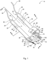
Figure 1 is a perspective view of a connection verifier; -
Figure 2A is a front elevational view of the connection verifier shown inFigure 1 ; -
Figure 2B is a top elevational view of the connection verifier shown inFigure 1 ; -
Figure 2C is a right side elevational view of the connection verifier shown inFigure 1 ; -
Figure 2D is a left side elevational view of the connection verifier shown inFigure 1 ; -
Figure 3 is a cross-sectional view of the connection verifier taken generally along line 3-3 inFigure 1 ; -
Figure 4 is a cross-sectional view of the connection verifier taken generally along line 4-4 inFigure 1 ; -
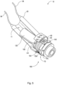
Figure 5 is a perspective view of the connection verifier shown inFigure 1 engaged with a fluid connection; -
Figure 6 is a right side view of the connection verifier engaged with the fluid connection shown inFigure 5 ; -
Figure 7 is a left side view of the connection verifier engaged with the fluid connection shown inFigure 5 ; -
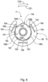
Figure 8 is an exploded view of the connection verifier partially engaged with the fluid connection shown inFigure 5 ; and, -
Figure 9 is a cross-sectional view of the fluid connection shown inFigure 5 . - At the outset, it should be appreciated that like drawing numbers on different drawing views identify identical, or functionally similar, structural elements. It is to be understood that the claims are not limited to the disclosed aspects.
- Furthermore, it is understood that this disclosure is not limited to the particular methodology, materials and modifications described and as such may, of course, vary. It is also understood that the terminology used herein is for the purpose of describing particular aspects only, and is not intended to limit the scope of the claims.
- Unless defined otherwise, all technical and scientific terms used herein have the same meaning as commonly understood to one of ordinary skill in the art to which this disclosure pertains. It should be understood that any methods, devices or materials similar or equivalent to those described herein can be used in the practice or testing of the example embodiments.
- It should be appreciated that the term "substantially" is synonymous with terms such as "nearly," "very nearly," "about," "approximately," "around," "bordering on," "close to," "essentially," "in the neighborhood of," "in the vicinity of," etc., and such terms may be used interchangeably as appearing in the specification and claims. It should be appreciated that the term "proximate" is synonymous with terms such as "nearby," "close," "adjacent," "neighboring," "immediate," "adjoining," etc., and such terms may be used interchangeably as appearing in the specification and claims. The term "approximately" is intended to mean values within ten percent of the specified value.
- By "non-rotatably connected" elements, we mean that: the elements are connected so that whenever one of the elements rotate, all the elements rotate; and relative rotation between the elements is not possible. Radial and/or axial movement of non-rotatably connected elements with respect to each other is possible, but not required.
- Adverting now to the figures,
Figure 1 is a perspective view ofconnection verifier 10.Figure 2A is a front elevational view ofconnection verifier 10.Figure 2B is a top elevational view ofconnection verifier 10.Figure 2C is a right side elevational view ofconnection verifier 10.Figure 2D is a left side elevational view ofconnection verifier 10.Connection verifier 10 generally compriseshousing 20,engagement plate 60, opening 11, and one or more cameras. In the embodiment shown in the figures, connection verifier comprisescameras connection verifier 10 may be integrally formed or formed by connecting separate components. -
Housing 20 compriseshandle 22 andhead 40.Handle 22 includes opening 21,end 24,end 26,inner shell 28, andouter shell 30.Inner shell 28 is a curved shell and is arranged radially inward from curvedouter shell 30.Inner shell 28 is connected toouter shell 30.Inner shell 28 open to formopening 21.Opening 21 allows clearance betweenhandle 22 andtube end form 120, as will be discussed in greater detail below. In an example embodiment,housing 20 does not comprise opening 21. In the embodiment shown,inner shell 28 is substantially parallel toouter shell 30. In an example embodiment,inner shell 28 is substantially non-parallel toouter shell 30. The space betweeninner shell 28 andouter shell 30 may be at least partially filled with material, or completely empty of material (i.e., hollow). In an example embodiment, the space betweeninner shell 28 andouter shell 30 is at least partially filled with materialproximate end 24. In the embodiment shown,handle 22 is generally U-shaped. It should be appreciated, however, that handle 22 may comprise any shape suitable for housing one or more cameras and allowing the proper line of sight to verify a fluid connection (e.g., rectangular, ovular, square, trapezoidal, parallelogram-shaped, triangular, etc.).End 24 comprisesholes Camera 80 is arranged inhole 32 andcamera 90 is arranged inhole 34.Camera 80 comprisesconduit 82 andwire 84.Camera 80 may further comprise light 81.Camera 90 comprisesconduit 92 andwire 94.Camera 90 may further comprise light 91. In an example embodiment,connection verifier 10 comprises one camera arranged in one hole inend 24. In an example embodiment,connection verifier 10 comprises three cameras arranged in three respective holes inend 24. It should be appreciated thatconnection verifier 10 may comprise any number of cameras arranged at any location therein suitable for verifying a fluid connection.Cameras head 40, specifically cutout 50, as will be discussed in greater detail below. As previously mentioned,connection verifier 10 further compriseslights proximate cameras cutout 50 andengagement plate 60 such that sufficient light is available forcameras Lights connection verifier 10 comprises one or more lights. It should be appreciated that any number of lights suitable to provide enough light to optically view the connection may be used. It should also be appreciated that the one or more lights may be positioned at any location inconnection verifier 10 suitable to provide enough light to optically view the fluid connection. -
Head 40 includesopening 41,end 42,end 44, radially inward facingsurface 46,inner shell 47,outer shell 48, andcutout 50.End 42 is connected to end 26. Radially inward facingsurface 46 andinner shell 47 are arranged radially inward fromouter shell 48.Cutout 50 is arranged ininner shell 47 and extends axially between radially inward facingsurface 46 andend 44. Radially inward facing surface andinner shell 47 open to formopening 41.Opening 41 is arranged to engagetube end form 120 offluid connection 160, as will be discussed in greater detail below.Head 40 is arranged at angle α relative to handle 22. Specifically,outer shell 48,inner shell 47, and radially inward facingsurface 66 of engagement plate are arranged at angle α relative to outer/inner shell 30. Angle α is arranged such thatcameras 80 and 90 (and lights 81 and 91) have a direct line of sight at the space betweenfluid connector 140 andtube end form 120, as will be discussed in greater detail below. Specifically, angle α is arranged such thatcameras snap ring 150 in the space betweenfluid connector 140 andtube end form 120. In an example embodiment, angle α is greater than or equal to 0 degrees and less than or equal to 90 degrees. In an example embodiment, angle α is greater than or equal to 10 degrees and less than or equal to 20 degrees. -
Engagement plate 60 comprisesopening 61,surface 62,surface 64, radially inward facingsurface 66, and radially outward facingsurface 68.Surface 62 is connected to end 44. Radially inward facingsurface 66 is arranged radially inward from radially outward facingsurface 68. Radially inward facingsurface 66 is connected to radially outward facingsurface 68. Radially inward facingsurface 66 opens to formopening 61.Opening 61 is arranged to engagetube end form 120 offluid connection 160, as will be discussed in greater detail below. In an example embodiment, radially inward facingsurface 66 is aligned with radially inward facingsurface 46, along an axial axis. In an example embodiment, radially inward facingsurface 66 is not aligned with radially inward facingsurface 46, along an axial axis.Surface 64 is arranged to engageend 141 of fluid connector 140 (seeFigure 5 ). Whenend 141 abuts againstsurface 64,tube end form 120 rests against radially inward facingsurface 46.Engagement plate 60 may further comprise one or more engagement members. In the embodiment shown,engagement plate 60 comprisesengagement member 70,engagement member 72, andengagement member 74.Engagement members surface 64. In an example embodiment,connection verifier 10 includes one or more engagement members. In the embodiments having one or more engagement members,fluid connection 160 is properly aligned such that the one or more cameras are able to find at least two of the protrusions of the snap ring, as will be discussed in greater detail below. In an example embodiment,connection verifier 10 does not include any engagement members. In this example embodiment,fluid connection 160 can be continuously rotated to find at least two of the protrusions of the snap ring, as will be discussed in greater detail below. -
Engagement member 70 comprises one or more prongs. In the embodiment shown,engagement member 70 comprisesprongs Prongs 70A-C are any pointed, projecting part used to align or hold a fluid connection.Prongs 70A-C may be tapered, include locking tabs on the distal ends, and be any suitable geometric shape (e.g., ovular, rectangular, trapezoidal, arcuate, etc.).Prongs Prong 70B is arranged betweenprongs Prong 70B is shorter in length thanprongs prong 70B comprises a length that is approximately 75% of the length ofprongs Engagement member 70 is arranged to engage a corner of the hexagonal head of a fluid connection. Specifically, prongs 70A and 70C are designed to engage either side of a corner of hexagonal head, as will be discussed in greater detail below.Prong 72B comprises a protrusion at its distal end and is arranged to engage a groove adjacent tohexagonal head 154.Prong 72B is arranged to "grip" and locate the fluid connector.Engagement member 70 is arranged to align the fluid connection such that the one or more cameras can find at least two of the protrusions of the snap ring of the fluid connection. It should be appreciated thatengagement member 70 can be arranged to align any fluid connection, for example, a fluid connection having a square head or an octagonal head, or any other fluid connection known in the art. -
Engagement member 72 comprises one or more prongs. In the embodiment shown,engagement member 72 comprisesprongs Prongs 72A-C are any pointed, projecting part used to align or hold an fluid connection.Prongs 72A-C may be tapered, include locking tabs on the distal ends, and be any suitable geometric shape (e.g., ovular, rectangular, trapezoidal, arcuate, etc.).Prongs Prong 72B is arranged betweenprongs Prong 72B is shorter in length thanprongs prong 72B comprises a length that is approximately 75% of the length ofprongs Engagement member 72 is arranged to engage a corner of the hexagonal head of a fluid connection. Specifically, prongs 72A and 72C are designed to engage either side of a corner of hexagonal head, as will be discussed in greater detail below.Prong 72B comprises a protrusion at its distal end and is arranged to engage a groove adjacent tohexagonal head 154.Prong 72B is arranged to "grip" and locate the fluid connector.Engagement member 72 is arranged to align the fluid connection such that the one or more cameras can find at least two of the protrusions of the snap ring of the fluid connection. It should be appreciated thatengagement member 72 can be arranged to align any fluid connection, for example, a fluid connection having a square head or an octagonal head, or any other fluid connection known in the art. -
Engagement member 74 comprises one or more prongs. In the embodiment shown,engagement member 74 comprisesprongs Prongs 74A-C are any pointed, projecting part used to align or hold an fluid connection.Prongs 74A-C may be tapered, include locking tabs on the distal ends, and be any suitable geometric shape (e.g., ovular, rectangular, trapezoidal, arcuate, etc.).Prongs Prong 74B is arranged betweenprongs Prong 74B is shorter in length thanprongs prong 74B comprises a length that is approximately 75% of the length ofprongs Engagement member 74 is arranged to engage a corner of the hexagonal head of a fluid connection. Specifically, prongs 74A and 74C are designed to engage either side of a corner of hexagonal head, as will be discussed in greater detail below.Prong 72B comprises a protrusion at its distal end and is arranged to engage a groove adjacent tohexagonal head 154.Prong 72B is arranged to "grip" and locate the fluid connector.Engagement member 74 is arranged to align the fluid connection such that the one or more cameras can find at least two of the protrusions of the snap ring of the fluid connection. It should be appreciated thatengagement member 74 can be arranged to align any fluid connection, for example, a fluid connection having a square head or an octagonal head, or any other fluid connection known in the art. -
Figure 3 is a cross-sectional view ofconnection verifier 10 taken generally along line 3-3 inFigure 1 .Camera 90 havinglight 91,conduit 92, andwire 94 is shown in hidden lines. As shown,conduit 92 is arranged inhole 34 inend 24.Camera 90 is directed such that its line of sight (shown by line L1) extends out ofcutout 50. Line L1 is substantially parallel toinner shell 28 andouter shell 30. Line L1 is arranged to extend out ofcutout 50 betweeninner shell 28 and radially inward facingsurface 66. In an example embodiment,camera 90 may be positioned at angle β relative toinner shell 28 and outer shell 30 (shown by line L2). -
Figure 4 is a cross-sectional view ofconnection verifier 10 taken generally along line 4-4 inFigure 1 .Cameras cameras cameras Cameras wires cameras - As previously mentioned,
connection verifier 10 may further comprise a transmission device that is electrically connected tocamera 80 and/orcamera 90 and optionally a memory device and/or a microcontroller. The transmission device is arranged to transmit an image, video, and/or a signal to a remote location indicating that a fluid connection is secure, or unsecure. For example, a programmable computer connected tocameras 80 and/or 90 may determine that at least two protrusions ofsnap ring 150 are visibly "snapped" over shoulder 127 (seeFigure 9 ) and then send a signal via a transmission device to a remote location indicating a verified fluid connection. This verification can of course be done manually by the user via a monitor, screen, or computing device. In an example embodiment, the transmission device is arranged to send a signal via an electrical cable such as a wire or a fiber optic cable (i.e., a physical form of connection). The transmission device may use inter-integrated circuit (I2C), controller area network (CAN), local interconnect network (LIN), or any suitable communication protocol known in the art. In an example embodiment, the transmission device is arranged to send a wireless communication to a receiver at a remote location which records the data sent (i.e., whether the fluid connection is securely connected, or not). The transmission device may transmit the data using any suitable method known in the art, for example, Bluetooth® communication, radio frequency, infrared, and Wi-Fi® communication. In an example embodiment, the transmission device may transmit the fluid connection identification number, the connection verifier identification number, the remaining life of the connection verifier, the vehicle identification number (VIN), the part number (e.g., engine, radiator, etc.) and serial number for that part, verification that a fluid connection is secure, and/or verification that a fluid connection is not secure. In an example embodiment, connection verifier can operate in conjunction with another device, such as a computer, to allow an electronic record to be kept of each inspection, and print a pass/fail label. -
Connection verifier 10 may further comprise a tool failure indicator, such as a light, a vibration device, or a sound device, to indicate thatconnection verifier 10 should be replaced. In this embodiment,connection verifier 10 could, for example, include a memory device or a microcontroller that is programmed with a predefined number, such that whenconnection verifier 10 is used a number of times equal to that predefined number, the tool failure indicator activates (i.e., the light turns on, the vibration device vibrates, the sound device creates a sound). The microcontroller may also tally the number oftimes connection verifier 10 is used, and using a preset remaining life calculation with a safety factor, continuously determine the remaining life of connection verifier. -
Figure 5 is a perspective view ofconnection verifier 10 shown inFigure 1 engaged withfluid connection 160.Figure 6 is a right side view ofconnection verifier 10 engaged withfluid connection 160 shown inFigure 5 .Fluid connection 160 generally comprisestube end form 120,fluid connector 140, andsnap ring 150. Fluid connections using tube end forms, fluid connectors, and snap rings are known in the art. When fully engaged, end 141 offluid connector 140 abuts againstsurface 64 and engagement members engage respective corners ofhexagonal head 154. For example, as shown inFigure 6 , prongs 70A-C are engaged withcorner 156F, prongs 72A-C are engaged withcorner 156D, and prongs 74A-C are engaged withcorner 156B. Engagement members may also be arranged to engage respective sides (instead of corners) of hexagonal head. -
Figure 7 is a left side view ofconnection verifier 10 engaged with thefluid connection 160 shown inFigure 5 . As shown,camera 80 is directed toward fluid connection 160 (as shown by line L3) and indicates thatprotrusion 152C is secured on (i.e., snapped over)shoulder 127 oftube end form 120.Camera 90 is directed toward fluid connection 160 (as shown by line L4) and indicates thatprotrusion 152A is secured on (i.e., snapped over)shoulder 127 oftube end form 120.Connection verifier 10 can be rotated in a circumferential direction such that engagement members engage different corners ofhexagonal head 154, thereby verifying different protrusions are secured over shoulder. However,cameras protrusions 152A-C are viewable. The reason for this is that typically, verifying that at least two ofprotrusions 152A-C are secured onshoulder 127 ensures a secure connection betweentube end form 120 andfluid connector 140. It should be appreciated that cameras can be arranged such that all three ofprotrusions 152A-C are viewable. In a one camera version ofconnection verifier 10, for example, at least one ofprotrusions 152A-C are visible from all six hexagonal faces, and two ofprotrusions 152A-C are visible on every other hexagonal face. It should be appreciated that, instead of individual engagement members and prongs, a sleeve can be arranged onsurface 64 to engagehexagonal head 154. The sleeve can be rotated relative to hexagonal head to engage therewith at various angles. -
Figure 8 is an exploded view ofconnection verifier 10 partially engaged withfluid connection 160. As shown,tube end form 120 is arranged inopenings Engagement plate 60 is rotated circumferentially until the engagement members are properly aligned with respective corners or respective sides ofhexagonal head 154. Whenend 141 abuts againstsurface 64 ofengagement plate 60,tube end form 120 is in contact with radially inward facingsurface 46, but a radial space exists betweentube end form 120 and radially inward facingsurface 66. This radial space allowscameras snap ring 150 radially betweentube end form 120 andfluid connector 140. -
Figure 9 is a cross-sectional view offluid connection 160 shown inFigure 5 . As previously discussed,fluid connection 160 generally comprisestube end form 120,fluid connector 140, andsnap ring 150. Fluid connections having a tube end form, a fluid connector and snap ring are known in the art. -
Tube end form 120 comprisesend 122,section 123,shoulder 127,section 129,end 132, and through-bore 121. Through-bore 121 extends throughtube end form 120 fromend 122 to end 132.Section 123 is arranged betweenend 122 andshoulder 127 and comprises radially outward facingsurface 124. Radially outward facingsurface 124 includes a substantially constant diameter.Shoulder 127 is arranged betweensection 123 andsection 129 and comprises radially outward facingsurface 126. Radially outward facingsurface 126 is a linear conical shape and increases in diameter in axial direction AD2.Section 129 is arranged betweenshoulder 127 and end 132 and comprises radially outward facingsurface 130. Radially outward facingsurface 130 includes a substantially constant diameter.Shoulder 127 is connected to radially outward facingsurface 130 viashoulder surface 128.Tube end form 120 is arranged to be inserted, specifically withend 122 first, intofluid connector 140.Tube end form 120 may utilize a straight ramp (i.e., constant linear ramp) or a variable diameter ramp, and is inserted intofluid connector 140 untilsnap ring 150 snaps overshoulder 127. It should be appreciated thattube end form 120 may be any traditional tube end form comprising a ramp, which extends radially outward and axially on the outer surface of the tube end form, to displace a snap ring or wire clip within the fluid connector to secure the tube end form within the fluid connector. In order to determine thatfluid connection 160 is securely connected,connection verifier 10 essentially verifies thatsnap ring 150 has "snapped" overshoulder 127. -
Fluid connector 140 comprisesend 141, through-bore 142, radially inward facingsurface 144, radially inward facingsurface 146, and radially outward facingsurface 148. Radially outward facingsurface 148 comprisesgroove 149.Snap ring 150 is arranged ingroove 149.Snap ring 150 comprisesprotrusions Figure 9 ).Protrusions 152A-C extend radially inward through holes ingroove 149 to engageshoulder 127, specifically,shoulder surface 128. Fluid connections that utilize snap rings arranged on fluid connectors to engage tube end forms are known in the art. - To verify that
fluid connection 160 is securely connected,connection verifier 10 is first arranged aroundtube end form 120 with cameras directed toward the radial space betweenfluid connector 140 andtube end form 120, as indicated by arrows A1 and A2. Through this radial space,cameras shoulder 127, thus verifying a secure connection betweentube end form 120 andfluid connector 140. - It will be appreciated that various aspects of the disclosure above and other features and functions, or alternatives thereof, may be desirably combined into many other different systems or applications, as long as they are covered by the appended claims.
-
- 10
- Connection verifier
- 11
- Opening
- 20
- Housing
- 21
- Opening
- 22
- Handle
- 24
- End
- 26
- End
- 28
- Inner shell
- 30
- Outer shell
- 32
- Hole
- 34
- Hole
- 40
- Head
- 41
- Opening
- 42
- End
- 44
- End
- 46
- Radially inward facing surface
- 47
- Inner shell
- 48
- Outer shell
- 50
- Cutout
- 60
- Engagement plate
- 61
- Opening
- 62
- Surface
- 64
- Surface
- 66
- Radially inward facing surface
- 68
- Radially outward facing surface
- 70
- Engagement member
- 70A
- Prong
- 70B
- Prong
- 70C
- Prong
- 72
- Engagement member
- 72A
- Prong
- 72B
- Prong
- 72C
- Prong
- 74
- Engagement member
- 74A
- Prong
- 74B
- Prong
- 74C
- Prong
- 80
- Camera
- 81
- Light
- 82
- Conduit
- 84
- Wire
- 90
- Camera
- 91
- Light
- 92
- Conduit
- 94
- Wire
- 120
- Tube end form
- 121
- Through-bore
- 122
- End
- 123
- Section
- 124
- Radially outward facing surface
- 126
- Radially outward facing surface
- 127
- Shoulder
- 128
- Shoulder surface
- 129
- Section
- 130
- Radially outward facing surface
- 132
- End
- 140
- Fluid connector
- 141
- End
- 142
- Through-bore
- 144
- Radially inward facing surface
- 146
- Radially inward facing surface
- 148
- Radially outward facing surface
- 149
- Groove
- 150
- Snap ring
- 152A
- Protrusion
- 152B
- Protrusion
- 152C
- Protrusion
- 154
- Hexagonal head
- 156A
- Corner
- 156B
- Corner
- 156C
- Corner
- 156D
- Corner
- 156E
- Corner
- 156F
- Corner
- 160
- Fluid connection
- AD1
- Axial direction
- AD2
- Axial direction
- CD1
- Circumferential direction
- CD2
- Circumferential direction
- L1
- Line
- L2
- Line
- A1
- Arrow
- A2
- Arrow
- α
- Angle
- β
- Angle
Claims (15)
- A connection verifier (10), comprising:a housing (20) including:a handle (22) comprising a first outer shell (30) and a first inner shell (28) connected to the first outer shell (30); and,a head (40) arranged to engage a fluid connection (160) and having a cutout (50); and,at least one camera (80, 90) arranged in the housing (20) radially between the first inner shell (28) and the first outer shell (30) and directed toward the cutout (50) to view the fluid connection (160).
- The connection verifier (10) as recited in Claim 1, further comprising an engagement plate (60) connected to the head (40), the engagement plate (60) arranged to engage a fluid connector (140) of the fluid connection (160).
- The connection verifier (10) as recited in Claim 2, wherein the engagement plate (60) comprises one or more engagement members (70, 72, 74) arranged to align the fluid connector (140).
- The connection verifier (10) as recited in Claim 1, further comprising at least one light (81, 91) arranged in the housing (20) and directed toward the cutout (50).
- The connection verifier (10) as recited in Claim 1, wherein the head (40) is arranged at an angle (α) relative to the handle (22), the angle (α) being greater than 0 degrees and less than 90 degrees.
- The connection verifier (10) as recited in Claim 1, further comprising:one or more engagement members (70, 72, 74) arranged to engage the fluid connection (160); and,one or more lights (81, 91) arranged in the housing (20).
- The connection verifier (10) as recited in Claim 6, wherein the head (40) comprises:a first end (42) connected to the housing (20);a second end (44) including the one or more engagement members (70, 72, 74) protruding therefrom;a second outer shell (48); and,a second inner shell (47) connected to the second outer shell (48) and having the cutout (50).
- The connection verifier (10) as recited in Claim 7, wherein each of the one or more engagement members (70, 72, 74) comprises at least one prong (70A-C, 72A-C, 74A-C) arranged to align a fluid connector (140) of the fluid connection (160).
- The connection verifier (10) as recited in Claim 7, wherein each of the one or more engagement members (70, 72, 74) comprises:a first prong (70A, 72A, 74A); and,a second prong (70B, 72B, 74B) adjacent the first prong (70A, 72A, 74A), wherein the first and second prongs (70A-B, 72A-B, 74A-B) are arranged to align a fluid connector (140) of the fluid connection (160).
- The connection verifier (10) as recited in Claim 7, wherein each of the one or more engagement members (70, 72, 74) comprises:a first prong (70A, 72A, 74A) having a first length;a second prong (70B, 72B, 74B) adjacent the first prong (70A, 72A, 74A) and having a second length, the second length being shorter than the first length; and,a third prong (70C, 72C, 74C) adjacent the second prong (70B, 72B, 74B) and having a third length, the third length being greater than the second length, wherein the first, second, and third prongs (70A-C, 72A-C, 74A-C) are arranged to align a fluid connector (140) of the fluid connection (160).
- The connection verifier (10) as recited in Claim 7, wherein the second outer shell (48) is arranged at an angle (α) relative to the first outer shell (30), the angle (α) being greater than 0 degrees and less than 90 degrees.
- The connection verifier (10) as recited in Claim 7, wherein the second inner shell (47) forms an opening (41) arranged to engage a tube end form (120) of the fluid connection (160).
- The connection verifier (10) as recited in Claim 1, 4, 8, 10 or 12, whereinthe handle (22) includes:a first end (24); anda second end (26);the head (40) includes:a third end (42) connected to the second end (26);a fourth end (44);a second outer shell (48); and,a second inner shell (47) connected to the second outer shell (48) and having the cutout (50); andthe connection verifier (10) further comprises an engagement plate (60), including:a first surface (62) connected to the fourth end;a second surface (64); and,one or more engagement members (70, 72, 74) connected to the second surface (64) and arranged to engage the fluid connection (160).
- The connection verifier (10) as recited in Claim 13, wherein the engagement plate (60) comprises a radially inward facing surface (66):offset from the first inner shell (28); and,arranged at an angle (α) relative to the first outer shell (30), wherein the angle (α) is greater than or equal to 0 degrees and less than or equal to 90 degrees.
- The connection verifier (10) as recited in Claim 13, wherein the handle (22), the head (40), and the engagement plate (60) are integrally formed.
Applications Claiming Priority (1)
| Application Number | Priority Date | Filing Date | Title |
|---|---|---|---|
| PCT/US2018/039320 WO2020005197A1 (en) | 2018-06-25 | 2018-06-25 | Connection verifier |
Publications (2)
| Publication Number | Publication Date |
|---|---|
| EP3810970A1 EP3810970A1 (en) | 2021-04-28 |
| EP3810970B1 true EP3810970B1 (en) | 2023-04-19 |
Family
ID=62976154
Family Applications (1)
| Application Number | Title | Priority Date | Filing Date |
|---|---|---|---|
| EP18743144.0A Active EP3810970B1 (en) | 2018-06-25 | 2018-06-25 | Connection verifier |
Country Status (10)
| Country | Link |
|---|---|
| US (1) | US11994475B2 (en) |
| EP (1) | EP3810970B1 (en) |
| JP (1) | JP7228602B2 (en) |
| KR (1) | KR102526341B1 (en) |
| CN (1) | CN112204292B (en) |
| BR (1) | BR112020022552A2 (en) |
| CA (1) | CA3099380C (en) |
| MX (1) | MX2020012751A (en) |
| RU (1) | RU2762609C1 (en) |
| WO (1) | WO2020005197A1 (en) |
Families Citing this family (1)
| Publication number | Priority date | Publication date | Assignee | Title |
|---|---|---|---|---|
| IT202000001057A1 (en) * | 2020-01-21 | 2021-07-21 | Visiontek Eng S R L | MOBILE APPARATUS FOR THREE-DIMENSIONAL OPTICAL MEASUREMENT FOR ROPES WITH ROPE ATTACHMENT DEVICE |
Family Cites Families (18)
| Publication number | Priority date | Publication date | Assignee | Title |
|---|---|---|---|---|
| JPS51116172A (en) | 1975-04-05 | 1976-10-13 | Nippon Steel Corp | A process for cooling hot slag |
| US7316428B2 (en) * | 2002-10-07 | 2008-01-08 | Tokai Rubber Industries, Ltd. | Connection verifying device and connection verifying structure for a pipe and a connector |
| JP3568947B1 (en) | 2004-02-25 | 2004-09-22 | 草野作工株式会社 | Perforator for branch pipe junction |
| US7484774B2 (en) * | 2005-05-03 | 2009-02-03 | Ti Group Automotive Systems, Llc | Redundant latch/verifier for a quick connector |
| US7431619B2 (en) * | 2006-06-30 | 2008-10-07 | Perceptron, Inc. | Detachable coupling for a remote inspection device |
| US8310604B2 (en) * | 2007-10-26 | 2012-11-13 | GE Sensing & Inspection Technologies, LP | Visual inspection apparatus having light source bank |
| JP5409655B2 (en) | 2008-02-05 | 2014-02-05 | スティーラブル・インスツルメンツ・ベー.フェー.ベー.アー. | Steerable tube |
| US8105442B2 (en) * | 2008-02-28 | 2012-01-31 | Welaptega Marine Limited | Tubular measurement system |
| SE533594C2 (en) * | 2008-11-11 | 2010-11-02 | Stora Enso Ab | Determination of surface properties of an object |
| FR2945100A1 (en) * | 2009-04-30 | 2010-11-05 | Hutchinson | CONNECTING CONNECTION BETWEEN A FLUID CONDUIT AND A RIGID BIT WITH A WIRELESS CONNECTION DEVICE AND A METHOD OF CONTROLLING THE CONNECTION |
| JP6166280B2 (en) | 2012-12-18 | 2017-07-19 | 株式会社移動ロボット研究所 | Piping inspection robot and piping inspection method |
| US9488753B2 (en) | 2013-05-16 | 2016-11-08 | Pgs Geophysical As | Marine geophysical equipment cleaner |
| JP6294627B2 (en) * | 2013-10-09 | 2018-03-14 | 株式会社クボタ | Pipe joint structure, seal member, joint state management method for pipe joint, and joint state management apparatus for pipe joint |
| CN104266030B (en) * | 2014-10-13 | 2016-04-13 | 北京市燃气集团有限责任公司 | A kind of visual pipe fitting blockage mechanism and stemming method thereof |
| JP6568710B2 (en) | 2015-04-24 | 2019-08-28 | 株式会社クボタ | Pipe inspection device |
| US10550982B2 (en) * | 2016-06-17 | 2020-02-04 | Ti Group Automotive Systems, Llc | Quick connector |
| US10443999B2 (en) * | 2016-06-22 | 2019-10-15 | Entegris, Inc. | Connection verification tool |
| JP2018013436A (en) | 2016-07-22 | 2018-01-25 | 株式会社クボタ | Bonding state evaluation method and bonding state evaluation apparatus |
-
2018
- 2018-06-25 MX MX2020012751A patent/MX2020012751A/en unknown
- 2018-06-25 JP JP2020571466A patent/JP7228602B2/en active Active
- 2018-06-25 WO PCT/US2018/039320 patent/WO2020005197A1/en not_active Ceased
- 2018-06-25 CA CA3099380A patent/CA3099380C/en active Active
- 2018-06-25 RU RU2020138432A patent/RU2762609C1/en active
- 2018-06-25 CN CN201880093925.1A patent/CN112204292B/en active Active
- 2018-06-25 KR KR1020217001880A patent/KR102526341B1/en active Active
- 2018-06-25 BR BR112020022552-5A patent/BR112020022552A2/en not_active Application Discontinuation
- 2018-06-25 US US17/253,665 patent/US11994475B2/en active Active
- 2018-06-25 EP EP18743144.0A patent/EP3810970B1/en active Active
Also Published As
| Publication number | Publication date |
|---|---|
| MX2020012751A (en) | 2021-02-26 |
| CA3099380C (en) | 2023-08-08 |
| JP7228602B2 (en) | 2023-02-24 |
| JP2021523336A (en) | 2021-09-02 |
| US20210262943A1 (en) | 2021-08-26 |
| WO2020005197A1 (en) | 2020-01-02 |
| CN112204292B (en) | 2022-08-09 |
| RU2762609C1 (en) | 2021-12-21 |
| KR102526341B1 (en) | 2023-04-28 |
| CA3099380A1 (en) | 2020-01-02 |
| CN112204292A (en) | 2021-01-08 |
| KR20210024045A (en) | 2021-03-04 |
| EP3810970A1 (en) | 2021-04-28 |
| US11994475B2 (en) | 2024-05-28 |
| BR112020022552A2 (en) | 2021-02-02 |
Similar Documents
| Publication | Publication Date | Title |
|---|---|---|
| US6862945B2 (en) | Camera guide for video pipe inspection system | |
| US20250151982A1 (en) | Medical device assembly and related methods | |
| CN105849452B (en) | Connector, release tool and device comprising connector and release tool | |
| KR102189767B1 (en) | Plug-in connector for fluid lines | |
| KR101409306B1 (en) | Device for connecting two rigid objects | |
| CN108020402A (en) | Quick connector detection instrument and method | |
| US20200187758A1 (en) | Smart Coupling System for Medical Instruments | |
| CA3099380C (en) | Connection verifier | |
| US11306854B2 (en) | Method and apparatus for installing an assurance cap onto a fluid connector using optical and induction sensors | |
| EP3306165B1 (en) | Threaded retainer | |
| CA3081661C (en) | Technologies for verifying a fluid connection | |
| EP3308430B1 (en) | Cable connector | |
| US11808392B2 (en) | Connection verifier | |
| JP5424170B2 (en) | Piping camera insertion aid and wiring aid |
Legal Events
| Date | Code | Title | Description |
|---|---|---|---|
| STAA | Information on the status of an ep patent application or granted ep patent |
Free format text: STATUS: UNKNOWN |
|
| STAA | Information on the status of an ep patent application or granted ep patent |
Free format text: STATUS: THE INTERNATIONAL PUBLICATION HAS BEEN MADE |
|
| PUAI | Public reference made under article 153(3) epc to a published international application that has entered the european phase |
Free format text: ORIGINAL CODE: 0009012 |
|
| STAA | Information on the status of an ep patent application or granted ep patent |
Free format text: STATUS: REQUEST FOR EXAMINATION WAS MADE |
|
| 17P | Request for examination filed |
Effective date: 20201111 |
|
| AK | Designated contracting states |
Kind code of ref document: A1 Designated state(s): AL AT BE BG CH CY CZ DE DK EE ES FI FR GB GR HR HU IE IS IT LI LT LU LV MC MK MT NL NO PL PT RO RS SE SI SK SM TR |
|
| AX | Request for extension of the european patent |
Extension state: BA ME |
|
| RIN1 | Information on inventor provided before grant (corrected) |
Inventor name: BUTTS, LAWRENCE Inventor name: HALL II, THOMAS EDWIN |
|
| DAV | Request for validation of the european patent (deleted) | ||
| DAX | Request for extension of the european patent (deleted) | ||
| GRAP | Despatch of communication of intention to grant a patent |
Free format text: ORIGINAL CODE: EPIDOSNIGR1 |
|
| STAA | Information on the status of an ep patent application or granted ep patent |
Free format text: STATUS: GRANT OF PATENT IS INTENDED |
|
| INTG | Intention to grant announced |
Effective date: 20230104 |
|
| GRAS | Grant fee paid |
Free format text: ORIGINAL CODE: EPIDOSNIGR3 |
|
| GRAA | (expected) grant |
Free format text: ORIGINAL CODE: 0009210 |
|
| STAA | Information on the status of an ep patent application or granted ep patent |
Free format text: STATUS: THE PATENT HAS BEEN GRANTED |
|
| AK | Designated contracting states |
Kind code of ref document: B1 Designated state(s): AL AT BE BG CH CY CZ DE DK EE ES FI FR GB GR HR HU IE IS IT LI LT LU LV MC MK MT NL NO PL PT RO RS SE SI SK SM TR |
|
| REG | Reference to a national code |
Ref country code: GB Ref legal event code: FG4D |
|
| REG | Reference to a national code |
Ref country code: DE Ref legal event code: R096 Ref document number: 602018048584 Country of ref document: DE |
|
| REG | Reference to a national code |
Ref country code: CH Ref legal event code: EP |
|
| REG | Reference to a national code |
Ref country code: IE Ref legal event code: FG4D |
|
| REG | Reference to a national code |
Ref country code: AT Ref legal event code: REF Ref document number: 1561435 Country of ref document: AT Kind code of ref document: T Effective date: 20230515 |
|
| REG | Reference to a national code |
Ref country code: LT Ref legal event code: MG9D |
|
| REG | Reference to a national code |
Ref country code: NL Ref legal event code: MP Effective date: 20230419 |
|
| REG | Reference to a national code |
Ref country code: AT Ref legal event code: MK05 Ref document number: 1561435 Country of ref document: AT Kind code of ref document: T Effective date: 20230419 |
|
| PG25 | Lapsed in a contracting state [announced via postgrant information from national office to epo] |
Ref country code: NL Free format text: LAPSE BECAUSE OF FAILURE TO SUBMIT A TRANSLATION OF THE DESCRIPTION OR TO PAY THE FEE WITHIN THE PRESCRIBED TIME-LIMIT Effective date: 20230419 |
|
| PG25 | Lapsed in a contracting state [announced via postgrant information from national office to epo] |
Ref country code: SE Free format text: LAPSE BECAUSE OF FAILURE TO SUBMIT A TRANSLATION OF THE DESCRIPTION OR TO PAY THE FEE WITHIN THE PRESCRIBED TIME-LIMIT Effective date: 20230419 Ref country code: PT Free format text: LAPSE BECAUSE OF FAILURE TO SUBMIT A TRANSLATION OF THE DESCRIPTION OR TO PAY THE FEE WITHIN THE PRESCRIBED TIME-LIMIT Effective date: 20230821 Ref country code: NO Free format text: LAPSE BECAUSE OF FAILURE TO SUBMIT A TRANSLATION OF THE DESCRIPTION OR TO PAY THE FEE WITHIN THE PRESCRIBED TIME-LIMIT Effective date: 20230719 Ref country code: ES Free format text: LAPSE BECAUSE OF FAILURE TO SUBMIT A TRANSLATION OF THE DESCRIPTION OR TO PAY THE FEE WITHIN THE PRESCRIBED TIME-LIMIT Effective date: 20230419 Ref country code: AT Free format text: LAPSE BECAUSE OF FAILURE TO SUBMIT A TRANSLATION OF THE DESCRIPTION OR TO PAY THE FEE WITHIN THE PRESCRIBED TIME-LIMIT Effective date: 20230419 |
|
| PG25 | Lapsed in a contracting state [announced via postgrant information from national office to epo] |
Ref country code: RS Free format text: LAPSE BECAUSE OF FAILURE TO SUBMIT A TRANSLATION OF THE DESCRIPTION OR TO PAY THE FEE WITHIN THE PRESCRIBED TIME-LIMIT Effective date: 20230419 Ref country code: PL Free format text: LAPSE BECAUSE OF FAILURE TO SUBMIT A TRANSLATION OF THE DESCRIPTION OR TO PAY THE FEE WITHIN THE PRESCRIBED TIME-LIMIT Effective date: 20230419 Ref country code: LV Free format text: LAPSE BECAUSE OF FAILURE TO SUBMIT A TRANSLATION OF THE DESCRIPTION OR TO PAY THE FEE WITHIN THE PRESCRIBED TIME-LIMIT Effective date: 20230419 Ref country code: LT Free format text: LAPSE BECAUSE OF FAILURE TO SUBMIT A TRANSLATION OF THE DESCRIPTION OR TO PAY THE FEE WITHIN THE PRESCRIBED TIME-LIMIT Effective date: 20230419 Ref country code: IS Free format text: LAPSE BECAUSE OF FAILURE TO SUBMIT A TRANSLATION OF THE DESCRIPTION OR TO PAY THE FEE WITHIN THE PRESCRIBED TIME-LIMIT Effective date: 20230819 Ref country code: HR Free format text: LAPSE BECAUSE OF FAILURE TO SUBMIT A TRANSLATION OF THE DESCRIPTION OR TO PAY THE FEE WITHIN THE PRESCRIBED TIME-LIMIT Effective date: 20230419 Ref country code: GR Free format text: LAPSE BECAUSE OF FAILURE TO SUBMIT A TRANSLATION OF THE DESCRIPTION OR TO PAY THE FEE WITHIN THE PRESCRIBED TIME-LIMIT Effective date: 20230720 Ref country code: AL Free format text: LAPSE BECAUSE OF FAILURE TO SUBMIT A TRANSLATION OF THE DESCRIPTION OR TO PAY THE FEE WITHIN THE PRESCRIBED TIME-LIMIT Effective date: 20230419 |
|
| PG25 | Lapsed in a contracting state [announced via postgrant information from national office to epo] |
Ref country code: FI Free format text: LAPSE BECAUSE OF FAILURE TO SUBMIT A TRANSLATION OF THE DESCRIPTION OR TO PAY THE FEE WITHIN THE PRESCRIBED TIME-LIMIT Effective date: 20230419 |
|
| PG25 | Lapsed in a contracting state [announced via postgrant information from national office to epo] |
Ref country code: SK Free format text: LAPSE BECAUSE OF FAILURE TO SUBMIT A TRANSLATION OF THE DESCRIPTION OR TO PAY THE FEE WITHIN THE PRESCRIBED TIME-LIMIT Effective date: 20230419 |
|
| PG25 | Lapsed in a contracting state [announced via postgrant information from national office to epo] |
Ref country code: MC Free format text: LAPSE BECAUSE OF FAILURE TO SUBMIT A TRANSLATION OF THE DESCRIPTION OR TO PAY THE FEE WITHIN THE PRESCRIBED TIME-LIMIT Effective date: 20230419 |
|
| REG | Reference to a national code |
Ref country code: DE Ref legal event code: R097 Ref document number: 602018048584 Country of ref document: DE |
|
| PG25 | Lapsed in a contracting state [announced via postgrant information from national office to epo] |
Ref country code: SM Free format text: LAPSE BECAUSE OF FAILURE TO SUBMIT A TRANSLATION OF THE DESCRIPTION OR TO PAY THE FEE WITHIN THE PRESCRIBED TIME-LIMIT Effective date: 20230419 Ref country code: SK Free format text: LAPSE BECAUSE OF FAILURE TO SUBMIT A TRANSLATION OF THE DESCRIPTION OR TO PAY THE FEE WITHIN THE PRESCRIBED TIME-LIMIT Effective date: 20230419 Ref country code: RO Free format text: LAPSE BECAUSE OF FAILURE TO SUBMIT A TRANSLATION OF THE DESCRIPTION OR TO PAY THE FEE WITHIN THE PRESCRIBED TIME-LIMIT Effective date: 20230419 Ref country code: MC Free format text: LAPSE BECAUSE OF FAILURE TO SUBMIT A TRANSLATION OF THE DESCRIPTION OR TO PAY THE FEE WITHIN THE PRESCRIBED TIME-LIMIT Effective date: 20230419 Ref country code: EE Free format text: LAPSE BECAUSE OF FAILURE TO SUBMIT A TRANSLATION OF THE DESCRIPTION OR TO PAY THE FEE WITHIN THE PRESCRIBED TIME-LIMIT Effective date: 20230419 Ref country code: DK Free format text: LAPSE BECAUSE OF FAILURE TO SUBMIT A TRANSLATION OF THE DESCRIPTION OR TO PAY THE FEE WITHIN THE PRESCRIBED TIME-LIMIT Effective date: 20230419 Ref country code: CZ Free format text: LAPSE BECAUSE OF FAILURE TO SUBMIT A TRANSLATION OF THE DESCRIPTION OR TO PAY THE FEE WITHIN THE PRESCRIBED TIME-LIMIT Effective date: 20230419 |
|
| REG | Reference to a national code |
Ref country code: CH Ref legal event code: PL |
|
| PLBE | No opposition filed within time limit |
Free format text: ORIGINAL CODE: 0009261 |
|
| STAA | Information on the status of an ep patent application or granted ep patent |
Free format text: STATUS: NO OPPOSITION FILED WITHIN TIME LIMIT |
|
| REG | Reference to a national code |
Ref country code: BE Ref legal event code: MM Effective date: 20230630 |
|
| PG25 | Lapsed in a contracting state [announced via postgrant information from national office to epo] |
Ref country code: LU Free format text: LAPSE BECAUSE OF NON-PAYMENT OF DUE FEES Effective date: 20230625 |
|
| 26N | No opposition filed |
Effective date: 20240122 |
|
| REG | Reference to a national code |
Ref country code: IE Ref legal event code: MM4A |
|
| PG25 | Lapsed in a contracting state [announced via postgrant information from national office to epo] |
Ref country code: LU Free format text: LAPSE BECAUSE OF NON-PAYMENT OF DUE FEES Effective date: 20230625 |
|
| PG25 | Lapsed in a contracting state [announced via postgrant information from national office to epo] |
Ref country code: IE Free format text: LAPSE BECAUSE OF NON-PAYMENT OF DUE FEES Effective date: 20230625 |
|
| PG25 | Lapsed in a contracting state [announced via postgrant information from national office to epo] |
Ref country code: IE Free format text: LAPSE BECAUSE OF NON-PAYMENT OF DUE FEES Effective date: 20230625 Ref country code: CH Free format text: LAPSE BECAUSE OF NON-PAYMENT OF DUE FEES Effective date: 20230630 |
|
| PG25 | Lapsed in a contracting state [announced via postgrant information from national office to epo] |
Ref country code: SI Free format text: LAPSE BECAUSE OF FAILURE TO SUBMIT A TRANSLATION OF THE DESCRIPTION OR TO PAY THE FEE WITHIN THE PRESCRIBED TIME-LIMIT Effective date: 20230419 |
|
| PG25 | Lapsed in a contracting state [announced via postgrant information from national office to epo] |
Ref country code: SI Free format text: LAPSE BECAUSE OF FAILURE TO SUBMIT A TRANSLATION OF THE DESCRIPTION OR TO PAY THE FEE WITHIN THE PRESCRIBED TIME-LIMIT Effective date: 20230419 Ref country code: FR Free format text: LAPSE BECAUSE OF NON-PAYMENT OF DUE FEES Effective date: 20230630 Ref country code: BE Free format text: LAPSE BECAUSE OF NON-PAYMENT OF DUE FEES Effective date: 20230630 |
|
| PG25 | Lapsed in a contracting state [announced via postgrant information from national office to epo] |
Ref country code: BG Free format text: LAPSE BECAUSE OF FAILURE TO SUBMIT A TRANSLATION OF THE DESCRIPTION OR TO PAY THE FEE WITHIN THE PRESCRIBED TIME-LIMIT Effective date: 20230419 |
|
| PG25 | Lapsed in a contracting state [announced via postgrant information from national office to epo] |
Ref country code: BG Free format text: LAPSE BECAUSE OF FAILURE TO SUBMIT A TRANSLATION OF THE DESCRIPTION OR TO PAY THE FEE WITHIN THE PRESCRIBED TIME-LIMIT Effective date: 20230419 |
|
| PGFP | Annual fee paid to national office [announced via postgrant information from national office to epo] |
Ref country code: DE Payment date: 20250617 Year of fee payment: 8 |
|
| PGFP | Annual fee paid to national office [announced via postgrant information from national office to epo] |
Ref country code: GB Payment date: 20250617 Year of fee payment: 8 |
|
| PG25 | Lapsed in a contracting state [announced via postgrant information from national office to epo] |
Ref country code: CY Free format text: LAPSE BECAUSE OF FAILURE TO SUBMIT A TRANSLATION OF THE DESCRIPTION OR TO PAY THE FEE WITHIN THE PRESCRIBED TIME-LIMIT; INVALID AB INITIO Effective date: 20180625 |
|
| PG25 | Lapsed in a contracting state [announced via postgrant information from national office to epo] |
Ref country code: HU Free format text: LAPSE BECAUSE OF FAILURE TO SUBMIT A TRANSLATION OF THE DESCRIPTION OR TO PAY THE FEE WITHIN THE PRESCRIBED TIME-LIMIT; INVALID AB INITIO Effective date: 20180625 |
|
| PGFP | Annual fee paid to national office [announced via postgrant information from national office to epo] |
Ref country code: IT Payment date: 20250623 Year of fee payment: 8 |
|
| PG25 | Lapsed in a contracting state [announced via postgrant information from national office to epo] |
Ref country code: TR Free format text: LAPSE BECAUSE OF FAILURE TO SUBMIT A TRANSLATION OF THE DESCRIPTION OR TO PAY THE FEE WITHIN THE PRESCRIBED TIME-LIMIT Effective date: 20230419 |