EP3810507B1 - An aircraft seat unit - Google Patents
An aircraft seat unit Download PDFInfo
- Publication number
- EP3810507B1 EP3810507B1 EP19734475.7A EP19734475A EP3810507B1 EP 3810507 B1 EP3810507 B1 EP 3810507B1 EP 19734475 A EP19734475 A EP 19734475A EP 3810507 B1 EP3810507 B1 EP 3810507B1
- Authority
- EP
- European Patent Office
- Prior art keywords
- seat
- moveable
- companion
- pan
- seat pan
- Prior art date
- Legal status (The legal status is an assumption and is not a legal conclusion. Google has not performed a legal analysis and makes no representation as to the accuracy of the status listed.)
- Active
Links
Images


Classifications
-
- B—PERFORMING OPERATIONS; TRANSPORTING
- B64—AIRCRAFT; AVIATION; COSMONAUTICS
- B64D—EQUIPMENT FOR FITTING IN OR TO AIRCRAFT; FLIGHT SUITS; PARACHUTES; ARRANGEMENT OR MOUNTING OF POWER PLANTS OR PROPULSION TRANSMISSIONS IN AIRCRAFT
- B64D11/00—Passenger or crew accommodation; Flight-deck installations not otherwise provided for
- B64D11/06—Arrangements of seats, or adaptations or details specially adapted for aircraft seats
- B64D11/0639—Arrangements of seats, or adaptations or details specially adapted for aircraft seats with features for adjustment or converting of seats
- B64D11/0644—Adjustable arm rests
-
- B—PERFORMING OPERATIONS; TRANSPORTING
- B64—AIRCRAFT; AVIATION; COSMONAUTICS
- B64D—EQUIPMENT FOR FITTING IN OR TO AIRCRAFT; FLIGHT SUITS; PARACHUTES; ARRANGEMENT OR MOUNTING OF POWER PLANTS OR PROPULSION TRANSMISSIONS IN AIRCRAFT
- B64D11/00—Passenger or crew accommodation; Flight-deck installations not otherwise provided for
- B64D11/06—Arrangements of seats, or adaptations or details specially adapted for aircraft seats
- B64D11/0602—Seat modules, i.e. seat systems including furniture separate from the seat itself
-
- B—PERFORMING OPERATIONS; TRANSPORTING
- B64—AIRCRAFT; AVIATION; COSMONAUTICS
- B64D—EQUIPMENT FOR FITTING IN OR TO AIRCRAFT; FLIGHT SUITS; PARACHUTES; ARRANGEMENT OR MOUNTING OF POWER PLANTS OR PROPULSION TRANSMISSIONS IN AIRCRAFT
- B64D11/00—Passenger or crew accommodation; Flight-deck installations not otherwise provided for
- B64D11/06—Arrangements of seats, or adaptations or details specially adapted for aircraft seats
-
- B—PERFORMING OPERATIONS; TRANSPORTING
- B60—VEHICLES IN GENERAL
- B60N—SEATS SPECIALLY ADAPTED FOR VEHICLES; VEHICLE PASSENGER ACCOMMODATION NOT OTHERWISE PROVIDED FOR
- B60N2/00—Seats specially adapted for vehicles; Arrangement or mounting of seats in vehicles
- B60N2/005—Arrangement or mounting of seats in vehicles, e.g. dismountable auxiliary seats
- B60N2/01—Arrangement of seats relative to one another
-
- B—PERFORMING OPERATIONS; TRANSPORTING
- B60—VEHICLES IN GENERAL
- B60N—SEATS SPECIALLY ADAPTED FOR VEHICLES; VEHICLE PASSENGER ACCOMMODATION NOT OTHERWISE PROVIDED FOR
- B60N2/00—Seats specially adapted for vehicles; Arrangement or mounting of seats in vehicles
- B60N2/02—Seats specially adapted for vehicles; Arrangement or mounting of seats in vehicles the seat or part thereof being movable, e.g. adjustable
- B60N2/20—Seats specially adapted for vehicles; Arrangement or mounting of seats in vehicles the seat or part thereof being movable, e.g. adjustable the back-rest being tiltable, e.g. to permit easy access
- B60N2/206—Seats specially adapted for vehicles; Arrangement or mounting of seats in vehicles the seat or part thereof being movable, e.g. adjustable the back-rest being tiltable, e.g. to permit easy access to a position in which it can be used as a support for objects, e.g. as a tray
-
- B—PERFORMING OPERATIONS; TRANSPORTING
- B60—VEHICLES IN GENERAL
- B60N—SEATS SPECIALLY ADAPTED FOR VEHICLES; VEHICLE PASSENGER ACCOMMODATION NOT OTHERWISE PROVIDED FOR
- B60N2/00—Seats specially adapted for vehicles; Arrangement or mounting of seats in vehicles
- B60N2/24—Seats specially adapted for vehicles; Arrangement or mounting of seats in vehicles for particular purposes or particular vehicles
- B60N2/32—Seats specially adapted for vehicles; Arrangement or mounting of seats in vehicles for particular purposes or particular vehicles convertible for other use
- B60N2/34—Seats specially adapted for vehicles; Arrangement or mounting of seats in vehicles for particular purposes or particular vehicles convertible for other use into a bed
-
- B—PERFORMING OPERATIONS; TRANSPORTING
- B60—VEHICLES IN GENERAL
- B60N—SEATS SPECIALLY ADAPTED FOR VEHICLES; VEHICLE PASSENGER ACCOMMODATION NOT OTHERWISE PROVIDED FOR
- B60N2/00—Seats specially adapted for vehicles; Arrangement or mounting of seats in vehicles
- B60N2/75—Arm-rests
- B60N2/753—Arm-rests movable to an inoperative position
- B60N2/757—Arm-rests movable to an inoperative position in a recess of the back-rest
-
- B—PERFORMING OPERATIONS; TRANSPORTING
- B64—AIRCRAFT; AVIATION; COSMONAUTICS
- B64D—EQUIPMENT FOR FITTING IN OR TO AIRCRAFT; FLIGHT SUITS; PARACHUTES; ARRANGEMENT OR MOUNTING OF POWER PLANTS OR PROPULSION TRANSMISSIONS IN AIRCRAFT
- B64D11/00—Passenger or crew accommodation; Flight-deck installations not otherwise provided for
- B64D11/06—Arrangements of seats, or adaptations or details specially adapted for aircraft seats
- B64D11/0601—Arrangement of seats for non-standard seating layouts, e.g. seats staggered horizontally or vertically, arranged in an angled or fishbone layout, or facing in other directions than the direction of flight
-
- B—PERFORMING OPERATIONS; TRANSPORTING
- B64—AIRCRAFT; AVIATION; COSMONAUTICS
- B64D—EQUIPMENT FOR FITTING IN OR TO AIRCRAFT; FLIGHT SUITS; PARACHUTES; ARRANGEMENT OR MOUNTING OF POWER PLANTS OR PROPULSION TRANSMISSIONS IN AIRCRAFT
- B64D11/00—Passenger or crew accommodation; Flight-deck installations not otherwise provided for
- B64D11/06—Arrangements of seats, or adaptations or details specially adapted for aircraft seats
- B64D11/0602—Seat modules, i.e. seat systems including furniture separate from the seat itself
- B64D11/0604—Seat modules, i.e. seat systems including furniture separate from the seat itself including a bed, e.g. cocoon type passenger seat modules
-
- B—PERFORMING OPERATIONS; TRANSPORTING
- B64—AIRCRAFT; AVIATION; COSMONAUTICS
- B64D—EQUIPMENT FOR FITTING IN OR TO AIRCRAFT; FLIGHT SUITS; PARACHUTES; ARRANGEMENT OR MOUNTING OF POWER PLANTS OR PROPULSION TRANSMISSIONS IN AIRCRAFT
- B64D11/00—Passenger or crew accommodation; Flight-deck installations not otherwise provided for
- B64D11/06—Arrangements of seats, or adaptations or details specially adapted for aircraft seats
- B64D11/0606—Arrangements of seats, or adaptations or details specially adapted for aircraft seats with privacy shells, screens, separators or the like
-
- B—PERFORMING OPERATIONS; TRANSPORTING
- B64—AIRCRAFT; AVIATION; COSMONAUTICS
- B64D—EQUIPMENT FOR FITTING IN OR TO AIRCRAFT; FLIGHT SUITS; PARACHUTES; ARRANGEMENT OR MOUNTING OF POWER PLANTS OR PROPULSION TRANSMISSIONS IN AIRCRAFT
- B64D11/00—Passenger or crew accommodation; Flight-deck installations not otherwise provided for
- B64D11/06—Arrangements of seats, or adaptations or details specially adapted for aircraft seats
- B64D11/0627—Seats combined with storage means
- B64D11/0636—Personal storage means or waste disposal bags
-
- B—PERFORMING OPERATIONS; TRANSPORTING
- B64—AIRCRAFT; AVIATION; COSMONAUTICS
- B64D—EQUIPMENT FOR FITTING IN OR TO AIRCRAFT; FLIGHT SUITS; PARACHUTES; ARRANGEMENT OR MOUNTING OF POWER PLANTS OR PROPULSION TRANSMISSIONS IN AIRCRAFT
- B64D11/00—Passenger or crew accommodation; Flight-deck installations not otherwise provided for
- B64D11/06—Arrangements of seats, or adaptations or details specially adapted for aircraft seats
- B64D11/0639—Arrangements of seats, or adaptations or details specially adapted for aircraft seats with features for adjustment or converting of seats
- B64D11/0641—Seats convertible into beds
Definitions
- the present disclosure relates to aircraft seat units.
- the present invention concerns aircraft seat units for providing seating to one or more passengers in an aircraft. More particularly, but not exclusively, this invention concerns an aircraft seat unit comprising a main seat, and a companion seat, the main seat and the companion seat facing each other, wherein the companion seat comprises a seat pan, providing a seat pan surface.
- the invention also concerns a method of deploying and a method of stowing a companion seat.
- the companion seat can be uncomfortable to sit on, especially for long periods of time. For example, a second passenger may not wish to sit in the companion seat to share a meal with a passenger in the main seat as the companion seat may not be comfortable enough.
- the present invention seeks to mitigate the above-mentioned problems. Alternatively or additionally, the present invention seeks to provide an improved aircraft seat unit.
- an aircraft seat unit comprising a main seat, and a companion seat, the main seat and the companion seat facing each other, wherein the companion seat comprises a seat pan, providing a seat pan surface, and a moveable seat element, the moveable seat element being moveable in relation to the seat pan between a stowed position, in which the companion seat provides an additional support surface for a main passenger in the main seat, and a deployed position, in which the moveable seat element provides a backrest surface for a companion passenger in the companion seat wherein the moveable seat element is slidable and/or rotatable with respect to the seat pan, wherein the moveable seat element is rotatable with respect to the seat pan, wherein the moveable seat element is rotatable about a rotation axis adjacent a rear edge of the moveable seat element, wherein the rotation axis is also adjacent a rear edge of the seat pan surface, wherein the seat pan surface is upwardly facing and is angled so that a front edge of the
- Having a moveable seat element allows a backrest surface to be provided for a passenger in the companion seat (when deployed). This makes the companion seat much more comfortable and a companion passenger may sit in the companion seat for longer.
- the companion seat may offer a level of comfort comparable to the companion passenger's designated seat or the main seat.
- the moveable seat element When the moveable seat element is stowed it provides an additional support surface, such as a foot or leg rest, for the main passenger in the main seat.
- the moveable seat element is dual use.
- the main seat is convertible between a seat configuration and a bed configuration and wherein, when the moveable seat element is in the stowed position, the additional support surface provided is an additional bed support surface for the main passenger.
- the companion seat as a bed surface for the main passenger in the main seat (when the main seat is in its bed configuration).
- the bed surface may be a foot-end bed surface.
- the seat pan surface is (at least partially) covered by the moveable seat element when the moveable seat element is in its stowed position.
- the seat pan surface is uncovered when the moveable seat element is in its deployed position.
- the seat pan surface and backrest surface are substantially the same size and/or shape.
- less than 50% (or 25%, or 10%, or substantially 0%) of both of the seat pan surface and the backrest surface are exposed when the movable seat element is in the stowed position.
- at least 50% (or 75%, or 90%, or substantially 100%) of the seat pan surface is covered by the movable seat element and at least 50% (or 75%, or 90%, or substantially 100%) of the backrest surface lies against the seat pan surface, when the movable seat element is in its stowed position.
- the moveable seat element is slidable and/or rotatable with respect to the seat pan. This allows the moveable seat element to be effectively moved in relation to the seat pan.
- the moveable seat element may slide (for example sliding sideways in relation to the seat pan or up and down in relation to the seat pan), rotate up from behind the seat pan or rotate up from the seat pan.
- the moveable seat element is rotatable with respect to the seat pan. This provides an effective deployment/stowage action that is easy for a passenger to operate.
- the moveable seat element is rotatable about a rotation axis adjacent, and preferably along, a rear edge of the moveable seat element. This allows the moveable seat element to be flipped up to be deployed.
- “rear” and “front” are in relation to conventional orientation of the relevant seat. i.e. the front of the seat is towards the direction of a passenger/the seat faces and the rear is towards the direction the passenger/the seat faces away from.
- the companion seat is facing the main seat (i.e. the front edge of the companion seat is nearest the main seat), the rear edge is the edge furthest away from the main seat.
- the rotation axis is also adjacent, and preferably along, a rear edge of the seat pan surface. This allows the moveable seat element to be flipped up to be deployed, in relation to the seat pan surface. This means the seat pan surface may be covered when the moveable seat element is stowed. This prevents damage to the seat pan surface, for example, caused by feet/legs of a passenger of the main seat.
- the seat pan surface is upwardly facing and is angled so that a front edge of the seat pan surface is higher than the rear edge of the seat pan surface.
- This provides a seat pan that is angled backwards (in relation to conventional orientation of the companion seat). This means that the passenger is secure in the seat with reduced risk of falling forwards out of the companion seat.
- the seat pan surface may be angled backwards (so as to be higher at the front of the seat pan) at an angle of 3 to 14 degrees relative to an aircraft floor upon which the companion seat is to be mounted upon.
- the seat pan surface angle is between 5 and 14 degrees and more preferably between 10 and 14 degrees.
- the backrest surface When the moveable seat element is in the stowed position, the backrest surface is downwardly facing and is correspondingly angled so as to lie against the seat pan surface. This allows a compact stowed arrangement (the backrest surface can be coplanar with the seat pan surface). It also allows for the backrest surface, when the moveable seat element is deployed, to be at a reclined angle, so as to provide additional comfort to the companion passenger.
- the additional support surface is upwardly facing and is substantially horizontal.
- the additional support surface such as a bed surface and/or foot/leg rest surface, to be in line with the angle of the main seat and provide an effective additional support surface.
- substantially horizontal may mean that the surface is substantially parallel to an aircraft floor. It also includes being at an angle of approximately 3 degrees to an aircraft floor so that the surface is substantially horizontal during flight of an aircraft.
- the seat pan surface is a size suitable for a companion passenger to sit on.
- the seat pan surface has a depth, between the front and rear edges, of at least 250mm. More preferably, the seat pan surface has a depth of at least 350mm. Even more preferably, the seat pan surface has a depth of at least 400mm.
- the movable seat element is rotatable about a rotation axis, with respect to the seat pan and wherein the rotation axis is adjacent the rear edge of the seat pan surface.
- the backrest surface and additional support surface may be non-co-planar and/or non-parallel.
- the backrest surface may provide a reclined backrest when the additional support surface is substantially vertical.
- the backrest surface may provide a reclined backrest, when the additional support surface is substantially vertical (at 90 degrees), of between 93 and 114 degrees, and preferably between 104 and 114 degrees.
- the angle between the backrest surface and the additional support surface is between 3 degrees and 24 degrees, and preferably between 14 and 24 degrees.
- the additional support surface is substantially horizontal (relative to the aircraft floor) when the backrest surface lies flush against the seat pan surface.
- This also provides a backrest recline angle of 93 degrees (relative to horizontal/aircraft floor), at an angle of 90 degrees to the seat pan surface.
- the additional support surface is substantially horizontal (relative to the aircraft floor) when the backrest surface lies flush against the seat pan surface.
- This also provides a backrest angle of 104 degrees (relative to horizontal/aircraft floor), at an angle of 90 degrees to the seat pan surface.
- the additional support surface is 10 degrees off horizontal (relative to the aircraft floor) when the backrest surface lies flush against the seat pan surface.
- This also provides a backrest angle of 114 degrees (relative to horizontal/aircraft floor), at an angle of 100 degrees to the seat pan surface.
- the aircraft seat unit may comprise a table in between the main seat and the companion seat. This allows for two passengers in the two seats to eat together from the same table or do work together using the table.
- the seat pan is moveable in relation to a companion seat support structure between a rear position at a first distance from the main seat and a forward position at a second, shorter distance from the main seat.
- a companion seat support structure between a rear position at a first distance from the main seat and a forward position at a second, shorter distance from the main seat.
- the moveable seat element and the seat pan are linked such that movement of one of the moveable seat element and the seat pan causes movement of the other of the moveable seat element and the seat pan. This allows for combined movement of the moveable seat element and of the seat pan, which makes deployment/stowage of the moveable seat element and movement of the seat pan easier.
- movement of the moveable seat element causes movement of the seat pan and/or movement of the seat pan causes movement of the moveable seat element. This means that a passenger moving one of the seat pan and moveable seat element does not have to physically move the other in order for it to move.
- backwards (rearwards) movement of the seat pan may cause stowage of the moveable seat element.
- forwards movement of the seat pan may cause deployment of the moveable seat element.
- stowage movement of the moveable seat element may cause backwards (rearwards) movement of the seat pan.
- deployment movement of the moveable seat element may cause forwards movement of the seat pan.
- the additional support surface has a first firmness and the seat pan surface has a second, different firmness.
- first firmness may be provided that is most suitable for use as a bed and/or foot/leg rest surface and a second, different firmness to be provided that is most suitable for a seat pan surface.
- the second firmness may be lower (less firm) than the first firmness.
- the backrest has a firmness that may be different to the firmness of the seat pan and/or additional support surface. This allows a backrest firmness to be provided that is most suitable for use as a back rest surface.
- the seat pan surface is a cushioned surface.
- the companion seat comprises at least one moveable arm rest moveable in relation to the moveable seat element between a stowed position and a deployed position, in which the companion seat provides an arm rest support surface for the companion passenger.
- Having a moveable arm rest that can be stowed also enables a compact stowage arrangement.
- the arm rest(s) may not be moveable when the moveable seat element is stowed.
- the arm rest(s) may be moveable when the moveable seat element is deployed.
- the arm rest surface has a firmness that may be different to the firmness of the seat pan and/or backrest and/or additional support surface. This allows an arm rest firmness to be provided that is most suitable for use as an arm rest surface.
- the moveable arm rest is rotatable with respect to the moveable seat element. This provides a deployment/stowage action that is easy and intuitive for a passenger to operate.
- the moveable arm rest is rotatable about a rotation axis adjacent, and preferably along, a rear edge of the moveable arm rest. This provides a large area of arm rest surface.
- the rear edge of the moveable arm rest is the edge furthest away from the main seat.
- the rotation axis is also adjacent, and preferably along, the backrest surface. This allows the arm rest to be effectively deployed in relation to the back rest.
- the moveable arm rest in the stowed position, lies substantially flush with the backrest surface. This enables a passenger to sit in the companion seat with the arm rest stowed and have a wide back rest surface to rest against. It also provides a compact stowage arrangement. This is because the moveable seat element can lie flush against the seat pan surface when stowed.
- the arm rests(s) abut against a portion of the moveable seat element when the arm rest(s) are in the deployed position. This prevents the arm rest(s) lowering further than substantially horizontal, or any other desired deployment angle.
- the companion seat comprises at least one moveable head rest moveable in relation to the moveable seat element between a stowed position and a deployed position, in which the companion seat provides a head rest support surface for the companion passenger.
- This provides even more comfort for a companion passenger. It also may provide protection for a TV monitor or other equipment behind the head rest support surface.
- the head rest may not be moveable when the moveable seat element is stowed.
- the head rest may be moveable when the moveable seat element is deployed.
- the moveable head rest may be rotatable about a rotation axis along a lower edge of the moveable head rest. This provides a large area of head rest surface.
- the rotation axis may also be along the backrest surface, for example an upper edge of the backrest surface. This allows the head rest to be effectively deployed in relation to the back rest.
- the moveable head rest In the stowed position, the moveable head rest may lie substantially flush with the backrest surface. This enables a passenger to sit in the companion seat with the head rest stowed and have a large back rest surface to rest against. It also provides a compact stowage arrangement. This is because the moveable seat element can lie flush against the seat pan surface when stowed.
- the seat pan of the companion seat is moveable up and down so the height of the additional support surface provided and/or the height of the seat pan surface varies relative to a height of the main seat.
- the companion seat may move on guide rails mounted on a shell or console of the aircraft seat unit.
- a support structure of the companion seat may also be moveable up and down with the seat pan.
- the companion seat comprises a storage container under the moveable seat element.
- This provides additional storage space for the main or companion passenger, for example for shoes or slippers.
- the storage container may be open.
- the storage container may comprise a closing mechanism, such as a rotatable door or a slidable drawer.
- the companion seat comprises a seat belt for use by the companion passenger.
- This allows the companion passenger to sit in the companion seat during flight (for example, during turbulence) and also, possibly during taxi, take-off and landing (TTL).
- TTL take-off and landing
- movement of the moveable seat element between the stowed and deployed positions is mechanically and/or electrically actuated. This allows for efficient stowage/deployment of the moveable seat element.
- latch There may be a latch that needs to be unlatched to allow the deployment and/or stowage movement to occur.
- a method of deploying a companion seat comprising the steps of providing an aircraft unit with a main seat and the companion seat, the main and companion seats facing each other, moving a moveable seat element of the companion seat in relation to a seat pan, providing a seat pan surface of the companion seat, from a stowed position, in which in which the companion seat provides an additional support surface for a main passenger in the main seat, and a deployed position, in which the moveable seat element provides a backrest surface for a companion passenger in the companion seat wherein the moveable seat element is slidable and/or rotatable with respect to the seat pan, wherein the moveable seat element is rotatable with respect to the seat pan, wherein the moveable seat element is rotatable about a rotation axis adjacent a rear edge of the moveable seat element, wherein the rotation axis is also adjacent a rear edge of the seat pan surface, wherein the seat pan surface is upwardly facing and is angled so that
- a method of stowing a companion seat comprising the steps of providing an aircraft unit with a main seat and the companion seat, the main and companion seats facing each other, moving a moveable seat element of the companion seat in relation to a seat pan, providing a seat pan surface of the companion seat, from a deployed position, in which the moveable seat element provides a backrest surface for a companion passenger in the companion seat and a stowed position, in which the companion seat provides an additional support surface for a main passenger in the main seat wherein the moveable seat element is slidable and/or rotatable with respect to the seat pan, wherein the moveable seat element is rotatable with respect to the seat pan, wherein the moveable seat element is rotatable about a rotation axis adjacent a rear edge of the moveable seat element, wherein the rotation axis is also adjacent a rear edge of the seat pan surface, wherein the seat pan surface is upwardly facing and is angled so that
- Figure 1 shows a perspective downwards looking view of a double aircraft seat unit 200 including two single aircraft seat units 100, both according to a first embodiment of the invention.
- Each aircraft seat unit 100 sits above a floor 101 and comprises a privacy shell 102 that surrounds a side console 103, main seat 105 and a companion seat 106.
- the main seat 105 and the companion seat 106 face each other, with the console 103 to one side of the seats 105, 106 and an accessway (a gap in the privacy shell 102) on the other side of the seats 105, 106.
- the aircraft seat unit 100 at the top of the Figure has the companion seat 106 in a deployed configuration, where a companion passenger can sit on it and have a backrest provided.
- the other aircraft seat unit 100 (at the bottom of the Figure) has the companion seat 106 in a stowed configuration where it is used as an ottoman for the main seat 105.
- the companion seat 106 comprises a support structure 111 that supports the rest of the companion seat 106.
- the support structure 111 also provides a storage container 150 under the rest of the companion seat 106.
- FIG 2a shows a schematic view of the companion seat 106 (excluding the support structure 111).
- the companion seat 106 comprises a seat pan 112 and a moveable seat element 120 pivotally mounted to flip up in relation to the seat pan 112.
- the moveable seat element 120 is in a stowed position (laying on top of the seat pan 112). In this position, an upwards facing surface 121 of the moveable seat element 120 provides a foot/leg rest surface, so as to provide an ottoman function for the main seat 105. If the main seat 105 was in a bed configuration, the surface 121 of the moveable seat element 120 may be used to make up part of the bed surface of the bed provided.
- Figure 2b shows a schematic view of the companion seat of Figure 2a , with the moveable seat element 120 in a deployed configuration, so that it has been flipped up to provide a backrest for the companion seat 106. More particularly, the previously downwardly facing surface of the moveable seat element 120 (opposite to surface 121) provides a slightly reclined backrest surface 124.
- the seat pan 112 has an upwardly facing (although actually slightly angled backwards) seat pan surface 115, a front edge 113 and a rear edge 114.
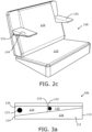
- Figure 2c shows a schematic view of the companion seat of Figures 2a and 2b , with the moveable seat element 120 in the deployed configuration.
- two arm rest 131, 132 (one on either side of the backrest surface 124) have been flipped down to provide an arm rest surface 134. Comparing Figures 2b and 2c , it can be seen that in their stowed positions (As in Figure 2b ), the arm rests 131, 132 sit flush with the backrest surface 124.
- FIG 3a shows a side schematic view of the companion seat of Figures 2a to 2c , with the moveable seat element 120 in the stowed configuration.
- the seat pan 112 comprises a shaped wedge cushion 116 with the front edge 113 being longer and extending higher than the rear edge 114. All of the cushioning is made of a graphite combustion modified high resilient polyurethane foam for use in aircraft seating, e.g. DAX (RTM) foams of varying density, provided by MGR Foamtex.
- the cushion 116 is provided with a density suitable for use as a seat pan. This is a density of approximately 57 - 66 kg/m 3 .
- the moveable seat element 120 is also a wedge shape with its rear edge (as shown in Figure 3a ) being longer and extending further downwards than its front edge. This means that the moveable seat element 120 and seat pan 112 make up a rectangle profile, when the moveable seat element 120 is in this stowed position.
- the moveable seat element 120 has an upper cushion layer 122 that provides the foot/leg/bed surface and a lower wedged cushion 125 that provides the backrest cushioning/surface.
- These cushions 122, 125 may be made of foam (or any other material) with different densities, and provide a different firmness.
- the cushion 122 is provided with a density suitable for use as a foot/leg rest/bed surface. This is a density of approximately 60 - 66 kg/m 3 .
- the cushion 125 is provided with a density suitable for use as a backrest. This is a density of approximately 43 - 57 kg/m 3 .
- 123 marks the pivot point of the moveable seat element 120 with respect to the seat pan 112.
- the cushioning 135 for the arm rest 131 can also be seen in this Figure and the pivot point 133 about which the arm rest pivots with respect to the moveable seat element 120.
- the cushion 135 is provided with a density suitable for use as an arm rest surface. This is a density of approximately 43 - 66 kg/m 3 .
- the armrests 131, 132 are deployed/stowed by flipping down/up in resistance to a friction hinge.
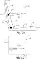
- Figure 3b shows a side schematic view of the companion seat 106 of Figures 2a to 2c , with the moveable seat element 120 in the deployed configuration and the two arm rests 131, 132 in their deployed configurations.
- the backrest surface 124 is reclined to provide a comfortable backrest for a passenger in the companion seat 106.
- the angle of the seat pan surface is slightly tilted back to also aid comfort of the companion passenger.
- an underside of the arm rests 131, 132 is directly abutting/resting on the cushion 125, so preventing the arm rests 131, 132 falling below this position.
- Figure 4a shows a side schematic view of part of one of the aircraft seat units 100 of Figure 1 , showing the companion seat 106 with the moveable seat element 120 in the stowed configuration. In this position, the seat pan 112 and moveable seat element 120 abut against the privacy screen 102.
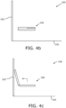
- the arrow shown shows that the seat pan 112 and moveable seat element 120 can slide forwards (i.e. towards the main seat 105), as shown in Figure 4b .
- the moveable seat element 120 can be flipped up to the deployed configuration, as shown in Figure 4c .
- the arm rests 131, 132 can be flipped down to be deployed, as shown in Figure 4d .
- Figure 4d also shows a tracking assembly 140 that is used to link the movement of the seat pan 112 and the moveable seat element 120 together.
- a tracking assembly 140 that is used to link the movement of the seat pan 112 and the moveable seat element 120 together.
- flipping up of the moveable seat element 120 causes the seat pan 112 to slide forwards (the movement from Figure 4a to Figure 4b ).
- flipping down of the moveable seat element 120 causes the seat pan 112 to slide backwards.
- the tracking assembly 140 comprises a guide rail mounted on the privacy screen 102 and a guide rail mounted on the console 103.
- the seat pan 112 is mounted on these guide rails.
- the seat pan 112 and moveable seat element 120 can be changed. This is done by the seat pan 112 being mounted on two guide rails; one attached to the privacy screen 102 and one to the side console 103.
- the seat 106 can be at a lower height when used as a foot/leg rest (ottoman function) or bed surface and a higher height (also allowing for the reduced height in view of flipping up the moveable seat element 120) for use as a seat for a companion passenger.
- the side console 103 provides a table that may be positioned between the two seats 105, 106. Hence, two passengers (one in the main seat 105 and one in the companion seat 106) can dine or work together, facing each other, using the same table.
- the companion seat 106 is provided with a seatbelt that a passenger in the companion seat 106 can use, for example during taxi, take-off, landing (TTL) or during turbulence.
- TTL take-off, landing
- latch activated by a handle
- the moveable seat element 120 can then be moved manually by simply flipping it up or down.
- a friction mechanism (not shown) allows the seat pan 112 and moveable seat element 120 to stay in a variety of position in between the stowed and deployed configurations.
- the storage container 150 provided may be closable, for example using a drawer or flip door.
- the companion seat 106 may be additionally provided with a headrest.
- the headrest may be attached to the moveable seat element 120 and may be flipped up (or otherwise deployed) in relation to the moveable seat element 120.
- the movement of the arm rests 131, 132 may be controlled using a latch handle.
- movement of the seat pan 112 causes movement of the moveable seat element 120 (rather than the other way round).
- the seat pan 112 may be caused to slide forwards by pressure being applied to a latch handle (perhaps located towards the front edge 113 of the seat pan 112).
- the latch handle When pressure is applied to the latch handle, the seat pan 112 can be slid forwards on the guide rails of the tracking assembly 140. This then causes the angle of the moveable seat element 120 to change and so control the recline angle of the backrest of the companion seat 106.
- the position of the seat pan 112 (and moveable seat element 120) is locked (for example, by a clamping mechanism which clamps the seat pan 112 in that position with respect to the guide rails).
- An alternative way to adjusting the height of the companion seat 106 is to mount the support structure 111 on a guide rail attached to the privacy screen 102 or console 103.
- Another alternative is to use a gas strut (like in a configurable office chair) to assist with the height adjustment.
- a user can press a handle (with no/little weight on the seat 106) to start upward movement (which stops when the handle is released). The user can use the same process (with weight on the seat 106) when the height is to be lowered.
- a further alternative is to control the height electronically.
- the companion seat 106 may instead may be moveable electronically, using an electrical actuation system.
- the cushioning of the companion seat may instead be a non-graphite combustion modified polyurethane foam or a closed cell foam made from PVDF (poly vinylidene fluoride).
Landscapes
- Engineering & Computer Science (AREA)
- Aviation & Aerospace Engineering (AREA)
- Transportation (AREA)
- Mechanical Engineering (AREA)
- Seats For Vehicles (AREA)
- Chairs For Special Purposes, Such As Reclining Chairs (AREA)
Description
- The present disclosure relates to aircraft seat units.
- The present invention concerns aircraft seat units for providing seating to one or more passengers in an aircraft. More particularly, but not exclusively, this invention concerns an aircraft seat unit comprising a main seat, and a companion seat, the main seat and the companion seat facing each other, wherein the companion seat comprises a seat pan, providing a seat pan surface. The invention also concerns a method of deploying and a method of stowing a companion seat.
- Many prior art aircraft seat units exist and many of them, in particular those designed for use in first or business class, comprise a main passenger seat and a companion seat that can also be used as an ottoman/foot rest or part of a bed surface of the main seat. An example can be seen in
GB 2412310 US2006097553 discloses a seating module that has an aisle seat and an aisle footstool located in an aisle side area. The seating module further includes a window seat and a window footstool located in a window side area. - However, in these arrangements, the companion seat can be uncomfortable to sit on, especially for long periods of time. For example, a second passenger may not wish to sit in the companion seat to share a meal with a passenger in the main seat as the companion seat may not be comfortable enough.
- The present invention seeks to mitigate the above-mentioned problems. Alternatively or additionally, the present invention seeks to provide an improved aircraft seat unit.
- The present invention provides, according to a first aspect, an aircraft seat unit comprising a main seat, and a companion seat, the main seat and the companion seat facing each other, wherein the companion seat comprises a seat pan, providing a seat pan surface, and a moveable seat element, the moveable seat element being moveable in relation to the seat pan between a stowed position, in which the companion seat provides an additional support surface for a main passenger in the main seat, and a deployed position, in which the moveable seat element provides a backrest surface for a companion passenger in the companion seat wherein the moveable seat element is slidable and/or rotatable with respect to the seat pan, wherein the moveable seat element is rotatable with respect to the seat pan, wherein the moveable seat element is rotatable about a rotation axis adjacent a rear edge of the moveable seat element, wherein the rotation axis is also adjacent a rear edge of the seat pan surface, wherein the seat pan surface is upwardly facing and is angled so that a front edge of the seat pan surface is higher than the rear edge of the seat pan surface; and wherein, when the moveable seat element is in the stowed position, the backrest surface is downwardly facing and is correspondingly angled so as to lie against the seat pan surface.
- Having a moveable seat element allows a backrest surface to be provided for a passenger in the companion seat (when deployed). This makes the companion seat much more comfortable and a companion passenger may sit in the companion seat for longer. Ideally, the companion seat may offer a level of comfort comparable to the companion passenger's designated seat or the main seat. When the moveable seat element is stowed it provides an additional support surface, such as a foot or leg rest, for the main passenger in the main seat. Hence, the moveable seat element is dual use.
- Preferably, the main seat is convertible between a seat configuration and a bed configuration and wherein, when the moveable seat element is in the stowed position, the additional support surface provided is an additional bed support surface for the main passenger. This allows a further use for the companion seat as a bed surface for the main passenger in the main seat (when the main seat is in its bed configuration). The bed surface may be a foot-end bed surface.
- Preferably, the seat pan surface is (at least partially) covered by the moveable seat element when the moveable seat element is in its stowed position. Preferably, the seat pan surface is uncovered when the moveable seat element is in its deployed position.
- Preferably, the seat pan surface and backrest surface are substantially the same size and/or shape. For example, less than 50% (or 25%, or 10%, or substantially 0%) of both of the seat pan surface and the backrest surface are exposed when the movable seat element is in the stowed position. In other words, at least 50% (or 75%, or 90%, or substantially 100%) of the seat pan surface is covered by the movable seat element and at least 50% (or 75%, or 90%, or substantially 100%) of the backrest surface lies against the seat pan surface, when the movable seat element is in its stowed position.
- The moveable seat element is slidable and/or rotatable with respect to the seat pan. This allows the moveable seat element to be effectively moved in relation to the seat pan. The moveable seat element may slide (for example sliding sideways in relation to the seat pan or up and down in relation to the seat pan), rotate up from behind the seat pan or rotate up from the seat pan.
- The moveable seat element is rotatable with respect to the seat pan. This provides an effective deployment/stowage action that is easy for a passenger to operate.
- The moveable seat element is rotatable about a rotation axis adjacent, and preferably along, a rear edge of the moveable seat element. This allows the moveable seat element to be flipped up to be deployed.
- In the context of the invention, "rear" and "front" (and forwards and backwards/rearwards) are in relation to conventional orientation of the relevant seat. i.e. the front of the seat is towards the direction of a passenger/the seat faces and the rear is towards the direction the passenger/the seat faces away from. As the companion seat is facing the main seat (i.e. the front edge of the companion seat is nearest the main seat), the rear edge is the edge furthest away from the main seat.
- The rotation axis is also adjacent, and preferably along, a rear edge of the seat pan surface. This allows the moveable seat element to be flipped up to be deployed, in relation to the seat pan surface. This means the seat pan surface may be covered when the moveable seat element is stowed. This prevents damage to the seat pan surface, for example, caused by feet/legs of a passenger of the main seat.
- The seat pan surface is upwardly facing and is angled so that a front edge of the seat pan surface is higher than the rear edge of the seat pan surface. This provides a seat pan that is angled backwards (in relation to conventional orientation of the companion seat). This means that the passenger is secure in the seat with reduced risk of falling forwards out of the companion seat. For example, the seat pan surface may be angled backwards (so as to be higher at the front of the seat pan) at an angle of 3 to 14 degrees relative to an aircraft floor upon which the companion seat is to be mounted upon. Preferably, the seat pan surface angle is between 5 and 14 degrees and more preferably between 10 and 14 degrees.
- When the moveable seat element is in the stowed position, the backrest surface is downwardly facing and is correspondingly angled so as to lie against the seat pan surface. This allows a compact stowed arrangement (the backrest surface can be coplanar with the seat pan surface). It also allows for the backrest surface, when the moveable seat element is deployed, to be at a reclined angle, so as to provide additional comfort to the companion passenger.
- Even more preferably, when the moveable seat element is in the stowed position, the additional support surface is upwardly facing and is substantially horizontal. This allows for the additional support surface, such as a bed surface and/or foot/leg rest surface, to be in line with the angle of the main seat and provide an effective additional support surface. Substantially horizontal may mean that the surface is substantially parallel to an aircraft floor. It also includes being at an angle of approximately 3 degrees to an aircraft floor so that the surface is substantially horizontal during flight of an aircraft.
- Preferably, the seat pan surface is a size suitable for a companion passenger to sit on. For example, the seat pan surface has a depth, between the front and rear edges, of at least 250mm. More preferably, the seat pan surface has a depth of at least 350mm. Even more preferably, the seat pan surface has a depth of at least 400mm. Preferably, the movable seat element is rotatable about a rotation axis, with respect to the seat pan and wherein the rotation axis is adjacent the rear edge of the seat pan surface.
- The backrest surface and additional support surface may be non-co-planar and/or non-parallel. The backrest surface may provide a reclined backrest when the additional support surface is substantially vertical.
- The backrest surface may provide a reclined backrest, when the additional support surface is substantially vertical (at 90 degrees), of between 93 and 114 degrees, and preferably between 104 and 114 degrees. Hence, the angle between the backrest surface and the additional support surface is between 3 degrees and 24 degrees, and preferably between 14 and 24 degrees. In an example, where the seat pan surface is at an angle of 3 degrees relative to an aircraft floor upon which the companion seat is to be mounted upon, and the angle between the backrest surface and the additional support surface is 3 degrees, the additional support surface is substantially horizontal (relative to the aircraft floor) when the backrest surface lies flush against the seat pan surface. This also provides a backrest recline angle of 93 degrees (relative to horizontal/aircraft floor), at an angle of 90 degrees to the seat pan surface. In another example, where the seat pan surface is at an angle of 14 degrees relative to an aircraft floor upon which the companion seat is to be mounted upon, and the angle between the backrest surface and the additional support surface is 14 degrees, the additional support surface is substantially horizontal (relative to the aircraft floor) when the backrest surface lies flush against the seat pan surface. This also provides a backrest angle of 104 degrees (relative to horizontal/aircraft floor), at an angle of 90 degrees to the seat pan surface. In another example, where the seat pan surface is at an angle of 14 degrees relative to an aircraft floor upon which the companion seat is to be mounted upon, and the angle between the backrest surface and the additional support surface is 24 degrees, the additional support surface is 10 degrees off horizontal (relative to the aircraft floor) when the backrest surface lies flush against the seat pan surface. This also provides a backrest angle of 114 degrees (relative to horizontal/aircraft floor), at an angle of 100 degrees to the seat pan surface.
- The aircraft seat unit may comprise a table in between the main seat and the companion seat. This allows for two passengers in the two seats to eat together from the same table or do work together using the table.
- Preferably, the seat pan is moveable in relation to a companion seat support structure between a rear position at a first distance from the main seat and a forward position at a second, shorter distance from the main seat. This allows a passenger in the companion seat to be seated nearer a main passenger in the main seat. Hence, an appropriate distance for dining or working (with a table provided between the two seats) can be provided.
- More preferably, the moveable seat element and the seat pan are linked such that movement of one of the moveable seat element and the seat pan causes movement of the other of the moveable seat element and the seat pan. This allows for combined movement of the moveable seat element and of the seat pan, which makes deployment/stowage of the moveable seat element and movement of the seat pan easier.
- Even more preferably, movement of the moveable seat element causes movement of the seat pan and/or movement of the seat pan causes movement of the moveable seat element. This means that a passenger moving one of the seat pan and moveable seat element does not have to physically move the other in order for it to move.
- For example, backwards (rearwards) movement of the seat pan may cause stowage of the moveable seat element. For example, forwards movement of the seat pan may cause deployment of the moveable seat element. For example, stowage movement of the moveable seat element may cause backwards (rearwards) movement of the seat pan. For example, deployment movement of the moveable seat element may cause forwards movement of the seat pan. Of course, any combination of the above examples are possible.
- Preferably, the additional support surface has a first firmness and the seat pan surface has a second, different firmness. This allows a first firmness to be provided that is most suitable for use as a bed and/or foot/leg rest surface and a second, different firmness to be provided that is most suitable for a seat pan surface. The second firmness may be lower (less firm) than the first firmness.
- The backrest has a firmness that may be different to the firmness of the seat pan and/or additional support surface. This allows a backrest firmness to be provided that is most suitable for use as a back rest surface.
- Preferably, the seat pan surface is a cushioned surface.
- Preferably, the companion seat comprises at least one moveable arm rest moveable in relation to the moveable seat element between a stowed position and a deployed position, in which the companion seat provides an arm rest support surface for the companion passenger. This makes the companion seat even more comfortable. Having a moveable arm rest that can be stowed also enables a compact stowage arrangement. There may be two moveable arm rests provided; one on either side of the companion seat. The arm rest(s) may not be moveable when the moveable seat element is stowed. The arm rest(s) may be moveable when the moveable seat element is deployed.
- The arm rest surface has a firmness that may be different to the firmness of the seat pan and/or backrest and/or additional support surface. This allows an arm rest firmness to be provided that is most suitable for use as an arm rest surface.
- Even more preferably, the moveable arm rest is rotatable with respect to the moveable seat element. This provides a deployment/stowage action that is easy and intuitive for a passenger to operate.
- Even more preferably, the moveable arm rest is rotatable about a rotation axis adjacent, and preferably along, a rear edge of the moveable arm rest. This provides a large area of arm rest surface. As the companion seat is facing the main seat (i.e. the front edge of the companion seat is nearest the main seat), the rear edge of the moveable arm rest is the edge furthest away from the main seat.
- Even more preferably, the rotation axis is also adjacent, and preferably along, the backrest surface. This allows the arm rest to be effectively deployed in relation to the back rest.
- Preferably, in the stowed position, the moveable arm rest lies substantially flush with the backrest surface. This enables a passenger to sit in the companion seat with the arm rest stowed and have a wide back rest surface to rest against. It also provides a compact stowage arrangement. This is because the moveable seat element can lie flush against the seat pan surface when stowed.
- Preferably, the arm rests(s) abut against a portion of the moveable seat element when the arm rest(s) are in the deployed position. This prevents the arm rest(s) lowering further than substantially horizontal, or any other desired deployment angle.
- Preferably, the companion seat comprises at least one moveable head rest moveable in relation to the moveable seat element between a stowed position and a deployed position, in which the companion seat provides a head rest support surface for the companion passenger. This provides even more comfort for a companion passenger. It also may provide protection for a TV monitor or other equipment behind the head rest support surface. The head rest may not be moveable when the moveable seat element is stowed. The head rest may be moveable when the moveable seat element is deployed.
- The moveable head rest may be rotatable about a rotation axis along a lower edge of the moveable head rest. This provides a large area of head rest surface. The rotation axis may also be along the backrest surface, for example an upper edge of the backrest surface. This allows the head rest to be effectively deployed in relation to the back rest.
- In the stowed position, the moveable head rest may lie substantially flush with the backrest surface. This enables a passenger to sit in the companion seat with the head rest stowed and have a large back rest surface to rest against. It also provides a compact stowage arrangement. This is because the moveable seat element can lie flush against the seat pan surface when stowed.
- Preferably, the seat pan of the companion seat is moveable up and down so the height of the additional support surface provided and/or the height of the seat pan surface varies relative to a height of the main seat. This allows the companion seat to be put at a suitable height for use as an additional support surface as well as a suitable height for a seat pan surface for a companion passenger. The companion seat may move on guide rails mounted on a shell or console of the aircraft seat unit. A support structure of the companion seat may also be moveable up and down with the seat pan.
- Preferably, the companion seat comprises a storage container under the moveable seat element. This provides additional storage space for the main or companion passenger, for example for shoes or slippers. The storage container may be open. Alternatively, the storage container may comprise a closing mechanism, such as a rotatable door or a slidable drawer.
- Preferably, the companion seat comprises a seat belt for use by the companion passenger. This allows the companion passenger to sit in the companion seat during flight (for example, during turbulence) and also, possibly during taxi, take-off and landing (TTL).
- Preferably, movement of the moveable seat element between the stowed and deployed positions is mechanically and/or electrically actuated. This allows for efficient stowage/deployment of the moveable seat element.
- There may be a handle or button that may be used to initiate or control actuation of the deployment/stowage.
- There may be a latch that needs to be unlatched to allow the deployment and/or stowage movement to occur.
- According to a second aspect of the invention there is also provided a method of deploying a companion seat, the method comprising the steps of providing an aircraft unit with a main seat and the companion seat, the main and companion seats facing each other, moving a moveable seat element of the companion seat in relation to a seat pan, providing a seat pan surface of the companion seat, from a stowed position, in which in which the companion seat provides an additional support surface for a main passenger in the main seat, and a deployed position, in which the moveable seat element provides a backrest surface for a companion passenger in the companion seat wherein the moveable seat element is slidable and/or rotatable with respect to the seat pan, wherein the moveable seat element is rotatable with respect to the seat pan, wherein the moveable seat element is rotatable about a rotation axis adjacent a rear edge of the moveable seat element, wherein the rotation axis is also adjacent a rear edge of the seat pan surface, wherein the seat pan surface is upwardly facing and is angled so that a front edge of the seat pan surface is higher than the rear edge of the seat pan surface; and wherein, when the moveable seat element is in the stowed position, the backrest surface is downwardly facing and is correspondingly angled so as to lie against the seat pan surface.
- According to a third aspect of the invention there is also provided a method of stowing a companion seat, the method comprising the steps of providing an aircraft unit with a main seat and the companion seat, the main and companion seats facing each other, moving a moveable seat element of the companion seat in relation to a seat pan, providing a seat pan surface of the companion seat, from a deployed position, in which the moveable seat element provides a backrest surface for a companion passenger in the companion seat and a stowed position, in which the companion seat provides an additional support surface for a main passenger in the main seat wherein the moveable seat element is slidable and/or rotatable with respect to the seat pan, wherein the moveable seat element is rotatable with respect to the seat pan, wherein the moveable seat element is rotatable about a rotation axis adjacent a rear edge of the moveable seat element, wherein the rotation axis is also adjacent a rear edge of the seat pan surface, wherein the seat pan surface is upwardly facing and is angled so that a front edge of the seat pan surface is higher than the rear edge of the seat pan surface; and wherein, when
the moveable seat element is in the stowed position, the backrest surface is downwardly facing and is correspondingly angled so as to lie against the seat pan surface. - It will of course be appreciated that features described in relation to one aspect of the present invention may be incorporated into other aspects of the present invention, as far as they fall within the scope of the appended claims. For example, the methods of the invention may incorporate any of the features described with reference to the apparatus of the invention and vice versa.
- Embodiments of the present invention will now be described by way of example only with reference to the accompanying schematic drawings of which:
-
Figure 1 shows a perspective downwards looking view of a double aircraft seat unit including two single aircraft seat units, both according to a first embodiment of the invention; -
Figure 2a shows a schematic view of a companion seat of one of the single aircraft seat units, the companion seat having a moveable seat element in a stowed configuration; -
Figure 2b shows a schematic view of the companion seat ofFigure 2a , the moveable seat element being in a deployed configuration; -
Figure 2c shows a schematic view of the companion seat ofFigures 2a and 2b , the moveable seat element being in a deployed configuration and the companion seat having two arm rests in their deployed configurations; -
Figure 3a shows a side schematic view of the companion seat ofFigures 2a to 2c , with the moveable seat element in the stowed configuration; -
Figure 3b shows a side schematic view of the companion seat ofFigures 2a to 2c , with the moveable seat element in the deployed configuration and the two arm rests in their deployed configurations; -
Figure 4a shows a side schematic view of part of one of the aircraft seat units ofFigure 1 , showing the companion seat ofFigures 2a to 2c andFigures 3a and3b , with the moveable seat element in the stowed configuration; -
Figure 4b shows a side schematic view likeFigure 4a , with the moveable seat element in the stowed configuration in a forwards position; -
Figure 4c shows a side schematic view likeFigures 4a and4b , with the moveable seat element in the deployed configuration in a forwards position; -
Figure 4d shows a side schematic view likeFigures 4a-4c , with the moveable seat element in the deployed configuration in a forwards position and with the two arm rests in their deployed configurations; and -
Figure 5 shows a perspective rear view of part of one of the aircraft seat units ofFigure 1 , showing a front view of the companion seat, with the moveable seat element in the stowed configuration. -
Figure 1 shows a perspective downwards looking view of a doubleaircraft seat unit 200 including two singleaircraft seat units 100, both according to a first embodiment of the invention. - Each
aircraft seat unit 100 sits above afloor 101 and comprises aprivacy shell 102 that surrounds aside console 103,main seat 105 and acompanion seat 106. Themain seat 105 and thecompanion seat 106 face each other, with theconsole 103 to one side of theseats seats privacy shell 102, behind thecompanion seat 106 is aTV monitor 104 for viewing by a passenger in themain seat 105. - In
Figure 1 , theaircraft seat unit 100 at the top of the Figure has thecompanion seat 106 in a deployed configuration, where a companion passenger can sit on it and have a backrest provided. The other aircraft seat unit 100 (at the bottom of the Figure) has thecompanion seat 106 in a stowed configuration where it is used as an ottoman for themain seat 105. - As shown in
Figure 5 , which is a perspective rear view of part of one of theaircraft seat units 100 ofFigure 1 , thecompanion seat 106 comprises asupport structure 111 that supports the rest of thecompanion seat 106. Thesupport structure 111 also provides astorage container 150 under the rest of thecompanion seat 106. -
Figure 2a shows a schematic view of the companion seat 106 (excluding the support structure 111). Thecompanion seat 106 comprises aseat pan 112 and amoveable seat element 120 pivotally mounted to flip up in relation to theseat pan 112. InFigure 2a , themoveable seat element 120 is in a stowed position (laying on top of the seat pan 112). In this position, an upwards facingsurface 121 of themoveable seat element 120 provides a foot/leg rest surface, so as to provide an ottoman function for themain seat 105. If themain seat 105 was in a bed configuration, thesurface 121 of themoveable seat element 120 may be used to make up part of the bed surface of the bed provided. -
Figure 2b shows a schematic view of the companion seat ofFigure 2a , with themoveable seat element 120 in a deployed configuration, so that it has been flipped up to provide a backrest for thecompanion seat 106. More particularly, the previously downwardly facing surface of the moveable seat element 120 (opposite to surface 121) provides a slightly reclinedbackrest surface 124. - In this configuration, it is easier to see other features of the
seat pan 112. Theseat pan 112 has an upwardly facing (although actually slightly angled backwards)seat pan surface 115, afront edge 113 and arear edge 114. -
Figure 2c shows a schematic view of the companion seat ofFigures 2a and 2b , with themoveable seat element 120 in the deployed configuration. Here, twoarm rest 131, 132 (one on either side of the backrest surface 124) have been flipped down to provide anarm rest surface 134. ComparingFigures 2b and2c , it can be seen that in their stowed positions (As inFigure 2b ), the arm rests 131, 132 sit flush with thebackrest surface 124. -
Figure 3a shows a side schematic view of the companion seat ofFigures 2a to 2c , with themoveable seat element 120 in the stowed configuration. Here, the shape of the different parts of thecompanion seat 106 can more easily be seen. Theseat pan 112 comprises a shapedwedge cushion 116 with thefront edge 113 being longer and extending higher than therear edge 114. All of the cushioning is made of a graphite combustion modified high resilient polyurethane foam for use in aircraft seating, e.g. DAX (RTM) foams of varying density, provided by MGR Foamtex. Thecushion 116 is provided with a density suitable for use as a seat pan. This is a density of approximately 57 - 66 kg/m3. - The
moveable seat element 120 is also a wedge shape with its rear edge (as shown inFigure 3a ) being longer and extending further downwards than its front edge. This means that themoveable seat element 120 andseat pan 112 make up a rectangle profile, when themoveable seat element 120 is in this stowed position. - The
moveable seat element 120 has anupper cushion layer 122 that provides the foot/leg/bed surface and a lower wedgedcushion 125 that provides the backrest cushioning/surface. Thesecushions cushion 122 is provided with a density suitable for use as a foot/leg rest/bed surface. This is a density of approximately 60 - 66 kg/m3. Thecushion 125 is provided with a density suitable for use as a backrest. This is a density of approximately 43 - 57 kg/m3. 123 marks the pivot point of themoveable seat element 120 with respect to theseat pan 112. - The cushioning 135 for the
arm rest 131 can also be seen in this Figure and thepivot point 133 about which the arm rest pivots with respect to themoveable seat element 120. Thecushion 135 is provided with a density suitable for use as an arm rest surface. This is a density of approximately 43 - 66 kg/m3. Thearmrests -
Figure 3b shows a side schematic view of thecompanion seat 106 ofFigures 2a to 2c , with themoveable seat element 120 in the deployed configuration and the two arm rests 131, 132 in their deployed configurations. Here, it can be clearly seen that in the deployed configuration, thebackrest surface 124 is reclined to provide a comfortable backrest for a passenger in thecompanion seat 106. In addition, the angle of the seat pan surface is slightly tilted back to also aid comfort of the companion passenger. As can be seen here, an underside of the arm rests 131, 132 is directly abutting/resting on thecushion 125, so preventing the arm rests 131, 132 falling below this position. -
Figure 4a shows a side schematic view of part of one of theaircraft seat units 100 ofFigure 1 , showing thecompanion seat 106 with themoveable seat element 120 in the stowed configuration. In this position, theseat pan 112 andmoveable seat element 120 abut against theprivacy screen 102. - The arrow shown shows that the
seat pan 112 andmoveable seat element 120 can slide forwards (i.e. towards the main seat 105), as shown inFigure 4b . Themoveable seat element 120 can be flipped up to the deployed configuration, as shown inFigure 4c . The arm rests 131, 132 can be flipped down to be deployed, as shown inFigure 4d . -
Figure 4d also shows a trackingassembly 140 that is used to link the movement of theseat pan 112 and themoveable seat element 120 together. Hence, flipping up of the moveable seat element 120 (the movement fromFigure 4b to Figure 4c ) causes theseat pan 112 to slide forwards (the movement fromFigure 4a to Figure 4b ). Similarly, flipping down of themoveable seat element 120 causes theseat pan 112 to slide backwards. - The tracking
assembly 140 comprises a guide rail mounted on theprivacy screen 102 and a guide rail mounted on theconsole 103. Theseat pan 112 is mounted on these guide rails. - It is also possible to change the height of the
seat pan 112 andmoveable seat element 120. This is done by theseat pan 112 being mounted on two guide rails; one attached to theprivacy screen 102 and one to theside console 103. Hence, theseat 106 can be at a lower height when used as a foot/leg rest (ottoman function) or bed surface and a higher height (also allowing for the reduced height in view of flipping up the moveable seat element 120) for use as a seat for a companion passenger. - Although not shown, the
side console 103 provides a table that may be positioned between the twoseats main seat 105 and one in the companion seat 106) can dine or work together, facing each other, using the same table. - Although not shown, the
companion seat 106 is provided with a seatbelt that a passenger in thecompanion seat 106 can use, for example during taxi, take-off, landing (TTL) or during turbulence. - Although not shown, there is latch (activated by a handle) that needs to be unlatched prior to the
moveable seat element 120 being able to move from the deployed and stowed positions. Themoveable seat element 120 can then be moved manually by simply flipping it up or down. A friction mechanism (not shown) allows theseat pan 112 andmoveable seat element 120 to stay in a variety of position in between the stowed and deployed configurations. - Whilst the present invention has been described and illustrated with reference to particular embodiments, it will be appreciated by those of ordinary skill in the art that the invention lends itself to many different variations not specifically illustrated herein. By way of example only, certain possible variations will now be described.
- The
storage container 150 provided may be closable, for example using a drawer or flip door. - The
companion seat 106 may be additionally provided with a headrest. The headrest may be attached to themoveable seat element 120 and may be flipped up (or otherwise deployed) in relation to themoveable seat element 120. - The movement of the arm rests 131, 132 may be controlled using a latch handle.
- Alternatively, it may be that movement of the
seat pan 112 causes movement of the moveable seat element 120 (rather than the other way round). For example, theseat pan 112 may be caused to slide forwards by pressure being applied to a latch handle (perhaps located towards thefront edge 113 of the seat pan 112). When pressure is applied to the latch handle, theseat pan 112 can be slid forwards on the guide rails of the trackingassembly 140. This then causes the angle of themoveable seat element 120 to change and so control the recline angle of the backrest of thecompanion seat 106. When the user releases the pressure from the latch handle, the position of the seat pan 112 (and moveable seat element 120) is locked (for example, by a clamping mechanism which clamps theseat pan 112 in that position with respect to the guide rails). - An alternative way to adjusting the height of the
companion seat 106 is to mount thesupport structure 111 on a guide rail attached to theprivacy screen 102 orconsole 103. Another alternative is to use a gas strut (like in a configurable office chair) to assist with the height adjustment. A user can press a handle (with no/little weight on the seat 106) to start upward movement (which stops when the handle is released). The user can use the same process (with weight on the seat 106) when the height is to be lowered. A further alternative is to control the height electronically. - The companion seat 106 (
seat pan 112 sliding and flipping of moveable seat element 120) may instead may be moveable electronically, using an electrical actuation system. - The cushioning of the companion seat may instead be a non-graphite combustion modified polyurethane foam or a closed cell foam made from PVDF (poly vinylidene fluoride).
- Reference should be made to the claims for determining the scope of the present invention, which is defined by the appended claims. It will also be appreciated by the reader that integers or features of the invention that are described as preferable, advantageous, convenient or the like are optional and do not limit the scope of the independent claims. Moreover, it is to be understood that such optional integers or features, whilst of possible benefit in some embodiments of the invention, may not be desirable, and may therefore be absent, in other embodiments.
Claims (12)
- An aircraft seat unit (100) comprising:- a main seat (105), and- a companion seat (106), the main seat (105) and the companion seat (106) facing each other,wherein the companion seat (106) comprises a seat pan (112), providing a seat pan surface (115), and a moveable seat element (120);characterised in that the moveable seat element (120) is moveable in relation to the seat pan (112) between a stowed position, in which the companion seat (106) provides an additional support surface (121) for a main passenger in the main seat (105), and a deployed position, in which the moveable seat element (120) provides a backrest surface (124) for a companion passenger in the companion seat (106);wherein the moveable seat element (120) is slidable and/or rotatable with respect to the seat pan (112);wherein the moveable seat element (120) is rotatable about a rotation axis adjacent a rear edge (114) of the moveable seat element (120), wherein the rotation axis is also adjacent a rear edge (114) of the seat pan surface (115), and wherein the seat pan surface (115) is upwardly facing and is angled so that a front edge (113) of the seat pan surface (115) is higher than the rear edge (114) of the seat pan surface (115); andwherein, when the moveable seat element (120) is in the stowed position, the backrest surface (124) is downwardly facing and is correspondingly angled so as to lie against the seat pan surface (115).
- An aircraft seat unit (100) as claimed in claim 1, wherein, when the moveable seat element (120) is in the stowed position, the additional support surface (121) is upwardly facing and is substantially horizontal.
- An aircraft seat unit as claimed in claims 1 or 2, wherein the seat pan (112) is moveable in relation to a companion seat (106) support structure (111) between a rear position at a first distance from the main seat (105) and a forward position at a second, shorter distance from the main seat (105).
- An aircraft seat unit as claimed in claim 3, wherein the moveable seat element (120) and the seat pan (112) are linked such that movement of one of the moveable seat element (120) and the seat pan (112) causes movement of the other of the moveable seat element (120) and the seat pan (112), and preferably wherein movement of the moveable seat element (120) causes movement of the seat pan (112) and/or movement of the seat pan (112) causes movement of the moveable seat element (120).
- An aircraft seat unit (100) as claimed in any of claims 1 to 4, wherein the additional support surface (121) has a first firmness and the seat pan surface (115) has a second, different firmness.
- An aircraft seat unit (100) as claimed in any preceding claim, wherein the companion seat (106) comprises at least one moveable arm rest (131, 132) moveable in relation to the moveable seat element (120) between a stowed position and a deployed position, in which the companion seat (106) provides an arm rest support surface (134) for the companion passenger.
- An aircraft seat unit (100) as claimed in claim 6, wherein the moveable arm rest (131), 132) is rotatable with respect to the moveable seat element (120), and preferably wherein the moveable arm rest (131, 132) is rotatable about a rotation axis (133) adjacent a rear edge of the moveable arm rest (131, 132), and preferably wherein the rotation axis (133) is also adjacent the backrest surface (124).
- An aircraft seat unit (100) as claimed in claim 6 or claim 7, wherein, in the stowed position, the moveable arm rest (131, 132) lies substantially flush with the backrest surface (124).
- An aircraft seat unit (100) as claimed in any preceding claim, wherein the companion seat (106) comprises at least one moveable head rest moveable in relation to the moveable seat element (120) between a stowed position and a deployed position, in which the companion seat (106) provides a head rest support surface for the companion passenger and/or wherein the seat pan (112) of the companion seat is moveable up and down so the height of the additional support surface (121) provided and/or the height of the seat pan surface (115) varies relative to a height of the main seat (105).
- An aircraft seat unit as claimed in any preceding claim, wherein the companion seat (106) comprises a seat belt for use by the companion passenger.
- A method of deploying a companion seat (106), the method comprising the steps of:- providing an aircraft unit (100) with a main seat (105) and the companion seat (106), the main and companion seats facing each other,- moving a moveable seat element (120) of the companion seat (106) in relation to a seat pan (112), providing a seat pan surface (115) of the companion seat (106), from a stowed position, in which the companion seat (106) provides an additional support surface (121) for a main passenger in the main seat (105), and a deployed position, in which the moveable seat element (120) provides a backrest surface (124) for a companion passenger in the companion seat (106),wherein the moveable seat element (120) is slidable and/or rotatable with respect to the seat pan (112);(112), wherein the moveable seat element (120) is rotatable about a rotation axis adjacent a rear edge (114) of the moveable seat element (120), wherein the rotation axis is also adjacent a rear edge (114) of the seat pan surface (115), and wherein the seat pan surface (115) is upwardly facing and is angled so that a front edge (113) of the seat pan surface (115) is higher than the rear edge (114) of the seat pan surface (115); andwherein, when the moveable seat element (120) is in the stowed position, the backrest surface (124) is downwardly facing and is correspondingly angled so as to lie against the seat pan surface (115).
- A method of stowing a companion seat (106), the method comprising the steps of:- providing an aircraft unit (100) with a main seat (105) and the companion seat (106), the main and companion seats facing each other,- moving a moveable seat element (120) of the companion seat (106) in relation to a seat pan (112), providing a seat pan surface (115) of the companion seat (106), from a deployed position, in which the moveable seat element (120) provides a backrest surface (124) for a companion passenger in the companion seat (106) and a stowed position, in which the companion seat (106) provides an additional support surface (121) for a main passenger in the main seat (105)wherein the moveable seat element (120) is slidable and/or rotatable with respect to the seat pan (112);(112), wherein the moveable seat element (120) is rotatable about a rotation axis adjacent a rear edge (114) of the moveable seat element (120), wherein the rotation axis is also adjacent a rear edge (114) of the seat pan surface (115), and wherein the seat pan surface (115) is upwardly facing and is angled so that a front edge (113) of the seat pan surface (115) is higher than the rear edge (114) of the seat pan surface (115); andwherein, when the moveable seat element (120) is in the stowed position, the backrest surface (124) is downwardly facing and is correspondingly angled so as to lie against the seat pan surface (115).
Applications Claiming Priority (2)
| Application Number | Priority Date | Filing Date | Title |
|---|---|---|---|
| GB1810174.1A GB2575025B (en) | 2018-06-21 | 2018-06-21 | An aircraft seat unit |
| PCT/GB2019/051735 WO2019243827A1 (en) | 2018-06-21 | 2019-06-20 | An aircraft seat unit |
Publications (2)
| Publication Number | Publication Date |
|---|---|
| EP3810507A1 EP3810507A1 (en) | 2021-04-28 |
| EP3810507B1 true EP3810507B1 (en) | 2024-07-24 |
Family
ID=63042492
Family Applications (1)
| Application Number | Title | Priority Date | Filing Date |
|---|---|---|---|
| EP19734475.7A Active EP3810507B1 (en) | 2018-06-21 | 2019-06-20 | An aircraft seat unit |
Country Status (5)
| Country | Link |
|---|---|
| US (1) | US11975844B2 (en) |
| EP (1) | EP3810507B1 (en) |
| CN (2) | CN119773970A (en) |
| GB (1) | GB2575025B (en) |
| WO (1) | WO2019243827A1 (en) |
Families Citing this family (4)
| Publication number | Priority date | Publication date | Assignee | Title |
|---|---|---|---|---|
| US11752912B1 (en) * | 2022-08-16 | 2023-09-12 | Ford Global Technologies, Llc | Vehicle seat assembly having assist handle |
| US12576971B2 (en) * | 2023-06-06 | 2026-03-17 | B/E Aerospace, Inc. | Passenger suite with secondary seat and amenities |
| US12559238B2 (en) | 2023-06-06 | 2026-02-24 | B/E Aerospace, Inc. | Configurable multi-class passenger seat assembly |
| WO2025028467A1 (en) * | 2023-08-02 | 2025-02-06 | テイ・エス テック株式会社 | Vehicle seat |
Citations (1)
| Publication number | Priority date | Publication date | Assignee | Title |
|---|---|---|---|---|
| US6305644B1 (en) * | 1999-11-10 | 2001-10-23 | B E Aerospace, Inc. | Aircraft cabin seat configuration with enhanced ingress/egress |
Family Cites Families (21)
| Publication number | Priority date | Publication date | Assignee | Title |
|---|---|---|---|---|
| US2632408A (en) * | 1951-10-04 | 1953-03-24 | Giles Eugene Manning | Compartmentizable seat for railroad coaches and the like |
| FR1596508A (en) * | 1968-07-18 | 1970-06-22 | ||
| US5310243A (en) * | 1993-03-26 | 1994-05-10 | Dbju, Inc. | Headrest support assembly for recliner chair |
| GB2406269B (en) | 2001-08-09 | 2005-10-05 | Virgin Atlantic Airways Ltd | A seat with a motorised reclining backrest |
| US7901005B2 (en) * | 2003-09-16 | 2011-03-08 | Honda Motor Co., Ltd | Vehicle seat |
| US20060097553A1 (en) * | 2004-10-13 | 2006-05-11 | David Spurlock | Airplane seating module system |
| GB0425323D0 (en) * | 2004-11-17 | 2004-12-22 | Britax Aircraft Interiors Uk L | Aircraft seat |
| US7303226B2 (en) * | 2005-04-07 | 2007-12-04 | International Truck Intellectual Property Company, Llc | Truck work office for mobile vehicle |
| GB2433433A (en) * | 2005-12-23 | 2007-06-27 | British Airways Plc | Aircraft passenger seat with secondary support surface |
| GB2448835B (en) * | 2005-12-23 | 2010-12-29 | British Airways Plc | Aircraft passenger seat |
| US7484786B2 (en) * | 2006-05-01 | 2009-02-03 | Toyota Motor Engineering & Manufacturing North America, Inc. | Adjustable rear seat |
| GB2438162A (en) * | 2006-05-19 | 2007-11-21 | British Airways Plc | Reclining aircraft seat convertible into bed |
| BG109675A (en) * | 2006-09-15 | 2008-07-31 | "Орт" Ад | Transformable furniture article |
| US7681945B1 (en) | 2008-10-02 | 2010-03-23 | L & P Property Management Company | Wall-avoiding convertible ottoman |
| KR101394083B1 (en) * | 2010-06-24 | 2014-05-13 | 존슨 컨트롤스 테크놀러지 컴퍼니 | Electro-mechanical push button vehicle seat actuation mechanism |
| US9193465B2 (en) * | 2011-11-08 | 2015-11-24 | B/E Aerospace, Inc. | Electromechanical actuation system for aircraft passenger suites and method |
| EP2828161B1 (en) * | 2012-03-19 | 2019-06-19 | B/E Aerospace Inc. | Premium class aircraft passenger suite |
| CN104271446B (en) * | 2012-03-20 | 2016-12-14 | B/E航空公司 | There is the deluxe class aircraft passenger inner room of independent seating area |
| DE102013008289A1 (en) * | 2013-05-15 | 2014-11-20 | Airbus Operations Gmbh | aircraft area |
| JP6567545B2 (en) * | 2014-04-07 | 2019-08-28 | サフラン シーツ | Seat unit |
| US10144515B2 (en) * | 2016-04-01 | 2018-12-04 | Encore Seats, Inc. | Aircraft seating assembly and components |
-
2018
- 2018-06-21 GB GB1810174.1A patent/GB2575025B/en active Active
-
2019
- 2019-06-20 US US17/254,721 patent/US11975844B2/en active Active
- 2019-06-20 EP EP19734475.7A patent/EP3810507B1/en active Active
- 2019-06-20 WO PCT/GB2019/051735 patent/WO2019243827A1/en not_active Ceased
- 2019-06-20 CN CN202510217668.XA patent/CN119773970A/en active Pending
- 2019-06-20 CN CN201980041208.9A patent/CN112566844A/en active Pending
Patent Citations (1)
| Publication number | Priority date | Publication date | Assignee | Title |
|---|---|---|---|---|
| US6305644B1 (en) * | 1999-11-10 | 2001-10-23 | B E Aerospace, Inc. | Aircraft cabin seat configuration with enhanced ingress/egress |
Also Published As
| Publication number | Publication date |
|---|---|
| CN119773970A (en) | 2025-04-08 |
| US11975844B2 (en) | 2024-05-07 |
| GB201810174D0 (en) | 2018-08-08 |
| EP3810507A1 (en) | 2021-04-28 |
| US20210269163A1 (en) | 2021-09-02 |
| GB2575025A (en) | 2020-01-01 |
| GB2575025B (en) | 2021-11-17 |
| WO2019243827A1 (en) | 2019-12-26 |
| CN112566844A (en) | 2021-03-26 |
Similar Documents
| Publication | Publication Date | Title |
|---|---|---|
| EP1116654B1 (en) | Passenger sleeper seat | |
| CA2935290C (en) | Aircraft seat | |
| EP3810507B1 (en) | An aircraft seat unit | |
| US7360742B2 (en) | Aircraft passenger accommodation unit with deployable bed | |
| US6305644B1 (en) | Aircraft cabin seat configuration with enhanced ingress/egress | |
| JP4900832B2 (en) | Aircraft seat | |
| JP2019214371A (en) | Seat unit | |
| EP2718184B1 (en) | Passenger seat assembly | |
| AU2005212212A1 (en) | Aircraft seating and seating arrangements | |
| EP3873806B1 (en) | Aircraft seat and cabin arrangement | |
| CA2987849C (en) | Transformable sofa | |
| US20050151405A1 (en) | Vehicle seating with protected living space | |
| EP3802320B1 (en) | Seat assembly with independent seat bottom tilt | |
| CN107108037A (en) | Aircraft seat | |
| US7111904B2 (en) | Vehicle seating supporting a perch position | |
| JP2024531368A (en) | Passenger seats for transport |
Legal Events
| Date | Code | Title | Description |
|---|---|---|---|
| STAA | Information on the status of an ep patent application or granted ep patent |
Free format text: STATUS: UNKNOWN |
|
| STAA | Information on the status of an ep patent application or granted ep patent |
Free format text: STATUS: THE INTERNATIONAL PUBLICATION HAS BEEN MADE |
|
| PUAI | Public reference made under article 153(3) epc to a published international application that has entered the european phase |
Free format text: ORIGINAL CODE: 0009012 |
|
| STAA | Information on the status of an ep patent application or granted ep patent |
Free format text: STATUS: REQUEST FOR EXAMINATION WAS MADE |
|
| 17P | Request for examination filed |
Effective date: 20201204 |
|
| AK | Designated contracting states |
Kind code of ref document: A1 Designated state(s): AL AT BE BG CH CY CZ DE DK EE ES FI FR GB GR HR HU IE IS IT LI LT LU LV MC MK MT NL NO PL PT RO RS SE SI SK SM TR |
|
| AX | Request for extension of the european patent |
Extension state: BA ME |
|
| DAV | Request for validation of the european patent (deleted) | ||
| DAX | Request for extension of the european patent (deleted) | ||
| STAA | Information on the status of an ep patent application or granted ep patent |
Free format text: STATUS: EXAMINATION IS IN PROGRESS |
|
| 17Q | First examination report despatched |
Effective date: 20220708 |
|
| GRAP | Despatch of communication of intention to grant a patent |
Free format text: ORIGINAL CODE: EPIDOSNIGR1 |
|
| STAA | Information on the status of an ep patent application or granted ep patent |
Free format text: STATUS: GRANT OF PATENT IS INTENDED |
|
| INTG | Intention to grant announced |
Effective date: 20231102 |
|
| GRAJ | Information related to disapproval of communication of intention to grant by the applicant or resumption of examination proceedings by the epo deleted |
Free format text: ORIGINAL CODE: EPIDOSDIGR1 |
|
| STAA | Information on the status of an ep patent application or granted ep patent |
Free format text: STATUS: EXAMINATION IS IN PROGRESS |
|
| INTC | Intention to grant announced (deleted) | ||
| GRAP | Despatch of communication of intention to grant a patent |
Free format text: ORIGINAL CODE: EPIDOSNIGR1 |
|
| STAA | Information on the status of an ep patent application or granted ep patent |
Free format text: STATUS: GRANT OF PATENT IS INTENDED |
|
| INTG | Intention to grant announced |
Effective date: 20240131 |
|
| GRAS | Grant fee paid |
Free format text: ORIGINAL CODE: EPIDOSNIGR3 |
|
| GRAA | (expected) grant |
Free format text: ORIGINAL CODE: 0009210 |
|
| STAA | Information on the status of an ep patent application or granted ep patent |
Free format text: STATUS: THE PATENT HAS BEEN GRANTED |
|
| AK | Designated contracting states |
Kind code of ref document: B1 Designated state(s): AL AT BE BG CH CY CZ DE DK EE ES FI FR GB GR HR HU IE IS IT LI LT LU LV MC MK MT NL NO PL PT RO RS SE SI SK SM TR |
|
| REG | Reference to a national code |
Ref country code: GB Ref legal event code: FG4D |
|
| REG | Reference to a national code |
Ref country code: CH Ref legal event code: EP |
|
| REG | Reference to a national code |
Ref country code: IE Ref legal event code: FG4D Ref country code: DE Ref legal event code: R096 Ref document number: 602019055697 Country of ref document: DE |
|
| REG | Reference to a national code |
Ref country code: LT Ref legal event code: MG9D |
|
| REG | Reference to a national code |
Ref country code: NL Ref legal event code: MP Effective date: 20240724 |
|
| PG25 | Lapsed in a contracting state [announced via postgrant information from national office to epo] |
Ref country code: PT Free format text: LAPSE BECAUSE OF FAILURE TO SUBMIT A TRANSLATION OF THE DESCRIPTION OR TO PAY THE FEE WITHIN THE PRESCRIBED TIME-LIMIT Effective date: 20241125 |
|
| REG | Reference to a national code |
Ref country code: AT Ref legal event code: MK05 Ref document number: 1706093 Country of ref document: AT Kind code of ref document: T Effective date: 20240724 |
|
| PG25 | Lapsed in a contracting state [announced via postgrant information from national office to epo] |
Ref country code: NL Free format text: LAPSE BECAUSE OF FAILURE TO SUBMIT A TRANSLATION OF THE DESCRIPTION OR TO PAY THE FEE WITHIN THE PRESCRIBED TIME-LIMIT Effective date: 20240724 |
|
| PG25 | Lapsed in a contracting state [announced via postgrant information from national office to epo] |
Ref country code: PT Free format text: LAPSE BECAUSE OF FAILURE TO SUBMIT A TRANSLATION OF THE DESCRIPTION OR TO PAY THE FEE WITHIN THE PRESCRIBED TIME-LIMIT Effective date: 20241125 Ref country code: NL Free format text: LAPSE BECAUSE OF FAILURE TO SUBMIT A TRANSLATION OF THE DESCRIPTION OR TO PAY THE FEE WITHIN THE PRESCRIBED TIME-LIMIT Effective date: 20240724 |
|
| PG25 | Lapsed in a contracting state [announced via postgrant information from national office to epo] |
Ref country code: NO Free format text: LAPSE BECAUSE OF FAILURE TO SUBMIT A TRANSLATION OF THE DESCRIPTION OR TO PAY THE FEE WITHIN THE PRESCRIBED TIME-LIMIT Effective date: 20241024 |
|
| PG25 | Lapsed in a contracting state [announced via postgrant information from national office to epo] |
Ref country code: GR Free format text: LAPSE BECAUSE OF FAILURE TO SUBMIT A TRANSLATION OF THE DESCRIPTION OR TO PAY THE FEE WITHIN THE PRESCRIBED TIME-LIMIT Effective date: 20241025 Ref country code: FI Free format text: LAPSE BECAUSE OF FAILURE TO SUBMIT A TRANSLATION OF THE DESCRIPTION OR TO PAY THE FEE WITHIN THE PRESCRIBED TIME-LIMIT Effective date: 20240724 Ref country code: PL Free format text: LAPSE BECAUSE OF FAILURE TO SUBMIT A TRANSLATION OF THE DESCRIPTION OR TO PAY THE FEE WITHIN THE PRESCRIBED TIME-LIMIT Effective date: 20240724 |
|
| PG25 | Lapsed in a contracting state [announced via postgrant information from national office to epo] |
Ref country code: BG Free format text: LAPSE BECAUSE OF FAILURE TO SUBMIT A TRANSLATION OF THE DESCRIPTION OR TO PAY THE FEE WITHIN THE PRESCRIBED TIME-LIMIT Effective date: 20240724 |
|
| PG25 | Lapsed in a contracting state [announced via postgrant information from national office to epo] |
Ref country code: LV Free format text: LAPSE BECAUSE OF FAILURE TO SUBMIT A TRANSLATION OF THE DESCRIPTION OR TO PAY THE FEE WITHIN THE PRESCRIBED TIME-LIMIT Effective date: 20240724 |
|
| PG25 | Lapsed in a contracting state [announced via postgrant information from national office to epo] |
Ref country code: AT Free format text: LAPSE BECAUSE OF FAILURE TO SUBMIT A TRANSLATION OF THE DESCRIPTION OR TO PAY THE FEE WITHIN THE PRESCRIBED TIME-LIMIT Effective date: 20240724 Ref country code: IS Free format text: LAPSE BECAUSE OF FAILURE TO SUBMIT A TRANSLATION OF THE DESCRIPTION OR TO PAY THE FEE WITHIN THE PRESCRIBED TIME-LIMIT Effective date: 20241124 |
|
| PG25 | Lapsed in a contracting state [announced via postgrant information from national office to epo] |
Ref country code: HR Free format text: LAPSE BECAUSE OF FAILURE TO SUBMIT A TRANSLATION OF THE DESCRIPTION OR TO PAY THE FEE WITHIN THE PRESCRIBED TIME-LIMIT Effective date: 20240724 |
|
| PG25 | Lapsed in a contracting state [announced via postgrant information from national office to epo] |
Ref country code: RS Free format text: LAPSE BECAUSE OF FAILURE TO SUBMIT A TRANSLATION OF THE DESCRIPTION OR TO PAY THE FEE WITHIN THE PRESCRIBED TIME-LIMIT Effective date: 20241024 Ref country code: ES Free format text: LAPSE BECAUSE OF FAILURE TO SUBMIT A TRANSLATION OF THE DESCRIPTION OR TO PAY THE FEE WITHIN THE PRESCRIBED TIME-LIMIT Effective date: 20240724 |
|
| PG25 | Lapsed in a contracting state [announced via postgrant information from national office to epo] |
Ref country code: RS Free format text: LAPSE BECAUSE OF FAILURE TO SUBMIT A TRANSLATION OF THE DESCRIPTION OR TO PAY THE FEE WITHIN THE PRESCRIBED TIME-LIMIT Effective date: 20241024 Ref country code: PL Free format text: LAPSE BECAUSE OF FAILURE TO SUBMIT A TRANSLATION OF THE DESCRIPTION OR TO PAY THE FEE WITHIN THE PRESCRIBED TIME-LIMIT Effective date: 20240724 Ref country code: NO Free format text: LAPSE BECAUSE OF FAILURE TO SUBMIT A TRANSLATION OF THE DESCRIPTION OR TO PAY THE FEE WITHIN THE PRESCRIBED TIME-LIMIT Effective date: 20241024 Ref country code: LV Free format text: LAPSE BECAUSE OF FAILURE TO SUBMIT A TRANSLATION OF THE DESCRIPTION OR TO PAY THE FEE WITHIN THE PRESCRIBED TIME-LIMIT Effective date: 20240724 Ref country code: IS Free format text: LAPSE BECAUSE OF FAILURE TO SUBMIT A TRANSLATION OF THE DESCRIPTION OR TO PAY THE FEE WITHIN THE PRESCRIBED TIME-LIMIT Effective date: 20241124 Ref country code: HR Free format text: LAPSE BECAUSE OF FAILURE TO SUBMIT A TRANSLATION OF THE DESCRIPTION OR TO PAY THE FEE WITHIN THE PRESCRIBED TIME-LIMIT Effective date: 20240724 Ref country code: GR Free format text: LAPSE BECAUSE OF FAILURE TO SUBMIT A TRANSLATION OF THE DESCRIPTION OR TO PAY THE FEE WITHIN THE PRESCRIBED TIME-LIMIT Effective date: 20241025 Ref country code: FI Free format text: LAPSE BECAUSE OF FAILURE TO SUBMIT A TRANSLATION OF THE DESCRIPTION OR TO PAY THE FEE WITHIN THE PRESCRIBED TIME-LIMIT Effective date: 20240724 Ref country code: ES Free format text: LAPSE BECAUSE OF FAILURE TO SUBMIT A TRANSLATION OF THE DESCRIPTION OR TO PAY THE FEE WITHIN THE PRESCRIBED TIME-LIMIT Effective date: 20240724 Ref country code: BG Free format text: LAPSE BECAUSE OF FAILURE TO SUBMIT A TRANSLATION OF THE DESCRIPTION OR TO PAY THE FEE WITHIN THE PRESCRIBED TIME-LIMIT Effective date: 20240724 Ref country code: AT Free format text: LAPSE BECAUSE OF FAILURE TO SUBMIT A TRANSLATION OF THE DESCRIPTION OR TO PAY THE FEE WITHIN THE PRESCRIBED TIME-LIMIT Effective date: 20240724 |
|
| PG25 | Lapsed in a contracting state [announced via postgrant information from national office to epo] |
Ref country code: SM Free format text: LAPSE BECAUSE OF FAILURE TO SUBMIT A TRANSLATION OF THE DESCRIPTION OR TO PAY THE FEE WITHIN THE PRESCRIBED TIME-LIMIT Effective date: 20240724 Ref country code: DK Free format text: LAPSE BECAUSE OF FAILURE TO SUBMIT A TRANSLATION OF THE DESCRIPTION OR TO PAY THE FEE WITHIN THE PRESCRIBED TIME-LIMIT Effective date: 20240724 Ref country code: RO Free format text: LAPSE BECAUSE OF FAILURE TO SUBMIT A TRANSLATION OF THE DESCRIPTION OR TO PAY THE FEE WITHIN THE PRESCRIBED TIME-LIMIT Effective date: 20240724 |
|
| PG25 | Lapsed in a contracting state [announced via postgrant information from national office to epo] |
Ref country code: EE Free format text: LAPSE BECAUSE OF FAILURE TO SUBMIT A TRANSLATION OF THE DESCRIPTION OR TO PAY THE FEE WITHIN THE PRESCRIBED TIME-LIMIT Effective date: 20240724 |
|
| PG25 | Lapsed in a contracting state [announced via postgrant information from national office to epo] |
Ref country code: CZ Free format text: LAPSE BECAUSE OF FAILURE TO SUBMIT A TRANSLATION OF THE DESCRIPTION OR TO PAY THE FEE WITHIN THE PRESCRIBED TIME-LIMIT Effective date: 20240724 |
|
| REG | Reference to a national code |
Ref country code: DE Ref legal event code: R097 Ref document number: 602019055697 Country of ref document: DE |
|
| PG25 | Lapsed in a contracting state [announced via postgrant information from national office to epo] |
Ref country code: SK Free format text: LAPSE BECAUSE OF FAILURE TO SUBMIT A TRANSLATION OF THE DESCRIPTION OR TO PAY THE FEE WITHIN THE PRESCRIBED TIME-LIMIT Effective date: 20240724 Ref country code: IT Free format text: LAPSE BECAUSE OF FAILURE TO SUBMIT A TRANSLATION OF THE DESCRIPTION OR TO PAY THE FEE WITHIN THE PRESCRIBED TIME-LIMIT Effective date: 20240724 |
|
| PLBE | No opposition filed within time limit |
Free format text: ORIGINAL CODE: 0009261 |
|
| STAA | Information on the status of an ep patent application or granted ep patent |
Free format text: STATUS: NO OPPOSITION FILED WITHIN TIME LIMIT |
|
| 26N | No opposition filed |
Effective date: 20250425 |
|
| PGFP | Annual fee paid to national office [announced via postgrant information from national office to epo] |
Ref country code: DE Payment date: 20250618 Year of fee payment: 7 |
|
| PGFP | Annual fee paid to national office [announced via postgrant information from national office to epo] |
Ref country code: GB Payment date: 20250625 Year of fee payment: 7 |
|
| PGFP | Annual fee paid to national office [announced via postgrant information from national office to epo] |
Ref country code: FR Payment date: 20250623 Year of fee payment: 7 |
|
| PG25 | Lapsed in a contracting state [announced via postgrant information from national office to epo] |
Ref country code: SE Free format text: LAPSE BECAUSE OF FAILURE TO SUBMIT A TRANSLATION OF THE DESCRIPTION OR TO PAY THE FEE WITHIN THE PRESCRIBED TIME-LIMIT Effective date: 20240724 |
|
| REG | Reference to a national code |
Ref country code: CH Ref legal event code: H13 Free format text: ST27 STATUS EVENT CODE: U-0-0-H10-H13 (AS PROVIDED BY THE NATIONAL OFFICE) Effective date: 20260127 |
|
| PG25 | Lapsed in a contracting state [announced via postgrant information from national office to epo] |
Ref country code: MC Free format text: LAPSE BECAUSE OF FAILURE TO SUBMIT A TRANSLATION OF THE DESCRIPTION OR TO PAY THE FEE WITHIN THE PRESCRIBED TIME-LIMIT Effective date: 20240724 |
|
| PG25 | Lapsed in a contracting state [announced via postgrant information from national office to epo] |
Ref country code: LU Free format text: LAPSE BECAUSE OF NON-PAYMENT OF DUE FEES Effective date: 20250620 |
|
| REG | Reference to a national code |
Ref country code: BE Ref legal event code: MM Effective date: 20250630 |
|
| PG25 | Lapsed in a contracting state [announced via postgrant information from national office to epo] |
Ref country code: IE Free format text: LAPSE BECAUSE OF NON-PAYMENT OF DUE FEES Effective date: 20250620 |
|
| PG25 | Lapsed in a contracting state [announced via postgrant information from national office to epo] |
Ref country code: BE Free format text: LAPSE BECAUSE OF NON-PAYMENT OF DUE FEES Effective date: 20250630 |
|
| PG25 | Lapsed in a contracting state [announced via postgrant information from national office to epo] |
Ref country code: CH Free format text: LAPSE BECAUSE OF NON-PAYMENT OF DUE FEES Effective date: 20250630 |