EP3810039B1 - Acetabular liner extraction - Google Patents
Acetabular liner extraction Download PDFInfo
- Publication number
- EP3810039B1 EP3810039B1 EP19745341.8A EP19745341A EP3810039B1 EP 3810039 B1 EP3810039 B1 EP 3810039B1 EP 19745341 A EP19745341 A EP 19745341A EP 3810039 B1 EP3810039 B1 EP 3810039B1
- Authority
- EP
- European Patent Office
- Prior art keywords
- bore
- shaft
- coupler
- handle
- tool assembly
- Prior art date
- Legal status (The legal status is an assumption and is not a legal conclusion. Google has not performed a legal analysis and makes no representation as to the accuracy of the status listed.)
- Active
Links
Images





Classifications
-
- A—HUMAN NECESSITIES
- A61—MEDICAL OR VETERINARY SCIENCE; HYGIENE
- A61F—FILTERS IMPLANTABLE INTO BLOOD VESSELS; PROSTHESES; DEVICES PROVIDING PATENCY TO, OR PREVENTING COLLAPSING OF, TUBULAR STRUCTURES OF THE BODY, e.g. STENTS; ORTHOPAEDIC, NURSING OR CONTRACEPTIVE DEVICES; FOMENTATION; TREATMENT OR PROTECTION OF EYES OR EARS; BANDAGES, DRESSINGS OR ABSORBENT PADS; FIRST-AID KITS
- A61F2/00—Filters implantable into blood vessels; Prostheses, i.e. artificial substitutes or replacements for parts of the body; Appliances for connecting them with the body; Devices providing patency to, or preventing collapsing of, tubular structures of the body, e.g. stents
- A61F2/02—Prostheses implantable into the body
- A61F2/30—Joints
- A61F2/46—Special tools for implanting artificial joints
- A61F2/4637—Special tools for implanting artificial joints for connecting or disconnecting two parts of a prosthesis
-
- A—HUMAN NECESSITIES
- A61—MEDICAL OR VETERINARY SCIENCE; HYGIENE
- A61F—FILTERS IMPLANTABLE INTO BLOOD VESSELS; PROSTHESES; DEVICES PROVIDING PATENCY TO, OR PREVENTING COLLAPSING OF, TUBULAR STRUCTURES OF THE BODY, e.g. STENTS; ORTHOPAEDIC, NURSING OR CONTRACEPTIVE DEVICES; FOMENTATION; TREATMENT OR PROTECTION OF EYES OR EARS; BANDAGES, DRESSINGS OR ABSORBENT PADS; FIRST-AID KITS
- A61F2/00—Filters implantable into blood vessels; Prostheses, i.e. artificial substitutes or replacements for parts of the body; Appliances for connecting them with the body; Devices providing patency to, or preventing collapsing of, tubular structures of the body, e.g. stents
- A61F2/02—Prostheses implantable into the body
- A61F2/30—Joints
- A61F2/32—Joints for the hip
- A61F2/34—Acetabular cups
-
- A—HUMAN NECESSITIES
- A61—MEDICAL OR VETERINARY SCIENCE; HYGIENE
- A61F—FILTERS IMPLANTABLE INTO BLOOD VESSELS; PROSTHESES; DEVICES PROVIDING PATENCY TO, OR PREVENTING COLLAPSING OF, TUBULAR STRUCTURES OF THE BODY, e.g. STENTS; ORTHOPAEDIC, NURSING OR CONTRACEPTIVE DEVICES; FOMENTATION; TREATMENT OR PROTECTION OF EYES OR EARS; BANDAGES, DRESSINGS OR ABSORBENT PADS; FIRST-AID KITS
- A61F2/00—Filters implantable into blood vessels; Prostheses, i.e. artificial substitutes or replacements for parts of the body; Appliances for connecting them with the body; Devices providing patency to, or preventing collapsing of, tubular structures of the body, e.g. stents
- A61F2/02—Prostheses implantable into the body
- A61F2/30—Joints
- A61F2/46—Special tools for implanting artificial joints
- A61F2/4603—Special tools for implanting artificial joints for insertion or extraction of endoprosthetic joints or of accessories thereof
- A61F2/4609—Special tools for implanting artificial joints for insertion or extraction of endoprosthetic joints or of accessories thereof of acetabular cups
-
- A—HUMAN NECESSITIES
- A61—MEDICAL OR VETERINARY SCIENCE; HYGIENE
- A61F—FILTERS IMPLANTABLE INTO BLOOD VESSELS; PROSTHESES; DEVICES PROVIDING PATENCY TO, OR PREVENTING COLLAPSING OF, TUBULAR STRUCTURES OF THE BODY, e.g. STENTS; ORTHOPAEDIC, NURSING OR CONTRACEPTIVE DEVICES; FOMENTATION; TREATMENT OR PROTECTION OF EYES OR EARS; BANDAGES, DRESSINGS OR ABSORBENT PADS; FIRST-AID KITS
- A61F2/00—Filters implantable into blood vessels; Prostheses, i.e. artificial substitutes or replacements for parts of the body; Appliances for connecting them with the body; Devices providing patency to, or preventing collapsing of, tubular structures of the body, e.g. stents
- A61F2/02—Prostheses implantable into the body
- A61F2/30—Joints
- A61F2/46—Special tools for implanting artificial joints
- A61F2/4603—Special tools for implanting artificial joints for insertion or extraction of endoprosthetic joints or of accessories thereof
-
- A—HUMAN NECESSITIES
- A61—MEDICAL OR VETERINARY SCIENCE; HYGIENE
- A61F—FILTERS IMPLANTABLE INTO BLOOD VESSELS; PROSTHESES; DEVICES PROVIDING PATENCY TO, OR PREVENTING COLLAPSING OF, TUBULAR STRUCTURES OF THE BODY, e.g. STENTS; ORTHOPAEDIC, NURSING OR CONTRACEPTIVE DEVICES; FOMENTATION; TREATMENT OR PROTECTION OF EYES OR EARS; BANDAGES, DRESSINGS OR ABSORBENT PADS; FIRST-AID KITS
- A61F2/00—Filters implantable into blood vessels; Prostheses, i.e. artificial substitutes or replacements for parts of the body; Appliances for connecting them with the body; Devices providing patency to, or preventing collapsing of, tubular structures of the body, e.g. stents
- A61F2/02—Prostheses implantable into the body
- A61F2/30—Joints
- A61F2002/30001—Additional features of subject-matter classified in A61F2/28, A61F2/30 and subgroups thereof
- A61F2002/30316—The prosthesis having different structural features at different locations within the same prosthesis; Connections between prosthetic parts; Special structural features of bone or joint prostheses not otherwise provided for
- A61F2002/30329—Connections or couplings between prosthetic parts, e.g. between modular parts; Connecting elements
- A61F2002/30428—Connections or couplings between prosthetic parts, e.g. between modular parts; Connecting elements made by inserting a protrusion into a slot
-
- A—HUMAN NECESSITIES
- A61—MEDICAL OR VETERINARY SCIENCE; HYGIENE
- A61F—FILTERS IMPLANTABLE INTO BLOOD VESSELS; PROSTHESES; DEVICES PROVIDING PATENCY TO, OR PREVENTING COLLAPSING OF, TUBULAR STRUCTURES OF THE BODY, e.g. STENTS; ORTHOPAEDIC, NURSING OR CONTRACEPTIVE DEVICES; FOMENTATION; TREATMENT OR PROTECTION OF EYES OR EARS; BANDAGES, DRESSINGS OR ABSORBENT PADS; FIRST-AID KITS
- A61F2/00—Filters implantable into blood vessels; Prostheses, i.e. artificial substitutes or replacements for parts of the body; Appliances for connecting them with the body; Devices providing patency to, or preventing collapsing of, tubular structures of the body, e.g. stents
- A61F2/02—Prostheses implantable into the body
- A61F2/30—Joints
- A61F2002/30001—Additional features of subject-matter classified in A61F2/28, A61F2/30 and subgroups thereof
- A61F2002/30667—Features concerning an interaction with the environment or a particular use of the prosthesis
- A61F2002/3069—Revision endoprostheses
-
- A—HUMAN NECESSITIES
- A61—MEDICAL OR VETERINARY SCIENCE; HYGIENE
- A61F—FILTERS IMPLANTABLE INTO BLOOD VESSELS; PROSTHESES; DEVICES PROVIDING PATENCY TO, OR PREVENTING COLLAPSING OF, TUBULAR STRUCTURES OF THE BODY, e.g. STENTS; ORTHOPAEDIC, NURSING OR CONTRACEPTIVE DEVICES; FOMENTATION; TREATMENT OR PROTECTION OF EYES OR EARS; BANDAGES, DRESSINGS OR ABSORBENT PADS; FIRST-AID KITS
- A61F2/00—Filters implantable into blood vessels; Prostheses, i.e. artificial substitutes or replacements for parts of the body; Appliances for connecting them with the body; Devices providing patency to, or preventing collapsing of, tubular structures of the body, e.g. stents
- A61F2/02—Prostheses implantable into the body
- A61F2/30—Joints
- A61F2/30767—Special external or bone-contacting surface, e.g. coating for improving bone ingrowth
- A61F2002/3093—Special external or bone-contacting surface, e.g. coating for improving bone ingrowth for promoting ingrowth of bone tissue
-
- A—HUMAN NECESSITIES
- A61—MEDICAL OR VETERINARY SCIENCE; HYGIENE
- A61F—FILTERS IMPLANTABLE INTO BLOOD VESSELS; PROSTHESES; DEVICES PROVIDING PATENCY TO, OR PREVENTING COLLAPSING OF, TUBULAR STRUCTURES OF THE BODY, e.g. STENTS; ORTHOPAEDIC, NURSING OR CONTRACEPTIVE DEVICES; FOMENTATION; TREATMENT OR PROTECTION OF EYES OR EARS; BANDAGES, DRESSINGS OR ABSORBENT PADS; FIRST-AID KITS
- A61F2/00—Filters implantable into blood vessels; Prostheses, i.e. artificial substitutes or replacements for parts of the body; Appliances for connecting them with the body; Devices providing patency to, or preventing collapsing of, tubular structures of the body, e.g. stents
- A61F2/02—Prostheses implantable into the body
- A61F2/30—Joints
- A61F2/46—Special tools for implanting artificial joints
- A61F2/4603—Special tools for implanting artificial joints for insertion or extraction of endoprosthetic joints or of accessories thereof
- A61F2002/4619—Special tools for implanting artificial joints for insertion or extraction of endoprosthetic joints or of accessories thereof for extraction
-
- A—HUMAN NECESSITIES
- A61—MEDICAL OR VETERINARY SCIENCE; HYGIENE
- A61F—FILTERS IMPLANTABLE INTO BLOOD VESSELS; PROSTHESES; DEVICES PROVIDING PATENCY TO, OR PREVENTING COLLAPSING OF, TUBULAR STRUCTURES OF THE BODY, e.g. STENTS; ORTHOPAEDIC, NURSING OR CONTRACEPTIVE DEVICES; FOMENTATION; TREATMENT OR PROTECTION OF EYES OR EARS; BANDAGES, DRESSINGS OR ABSORBENT PADS; FIRST-AID KITS
- A61F2/00—Filters implantable into blood vessels; Prostheses, i.e. artificial substitutes or replacements for parts of the body; Appliances for connecting them with the body; Devices providing patency to, or preventing collapsing of, tubular structures of the body, e.g. stents
- A61F2/02—Prostheses implantable into the body
- A61F2/30—Joints
- A61F2/46—Special tools for implanting artificial joints
- A61F2/4637—Special tools for implanting artificial joints for connecting or disconnecting two parts of a prosthesis
- A61F2002/4641—Special tools for implanting artificial joints for connecting or disconnecting two parts of a prosthesis for disconnecting
-
- A—HUMAN NECESSITIES
- A61—MEDICAL OR VETERINARY SCIENCE; HYGIENE
- A61F—FILTERS IMPLANTABLE INTO BLOOD VESSELS; PROSTHESES; DEVICES PROVIDING PATENCY TO, OR PREVENTING COLLAPSING OF, TUBULAR STRUCTURES OF THE BODY, e.g. STENTS; ORTHOPAEDIC, NURSING OR CONTRACEPTIVE DEVICES; FOMENTATION; TREATMENT OR PROTECTION OF EYES OR EARS; BANDAGES, DRESSINGS OR ABSORBENT PADS; FIRST-AID KITS
- A61F2/00—Filters implantable into blood vessels; Prostheses, i.e. artificial substitutes or replacements for parts of the body; Appliances for connecting them with the body; Devices providing patency to, or preventing collapsing of, tubular structures of the body, e.g. stents
- A61F2/02—Prostheses implantable into the body
- A61F2/30—Joints
- A61F2/46—Special tools for implanting artificial joints
- A61F2002/4681—Special tools for implanting artificial joints by applying mechanical shocks, e.g. by hammering
Definitions
- an outer shell can be secured to an acetabulum of a hip of a patient where the outer shell is configured to promote bony ingrowth to obtain a strong connection between the prosthesis in the hip.
- a liner is secured to a concave inner side of the shell to provide a smooth and resilient articulation surface for interaction with a femoral head or a femoral implant. In some cases, the liner must be removed during a revision procedure.
- US 2014/228854 , US2003/187512 and US2007/005144 disclose tool assemblies.
- the handle 110 can be can be a rigid or semi-rigid body extending proximally-to-distally along the axis A.
- the handle 110 can be sized and shaped to be grasped and operated.
- the handle 110 is coupled to the shaft 112 at a distal portion of the handle 110, as described below in further detail.
- FIG. 2B shows further details of each of the handle 110, the shaft 112, and the coupler 116.
- the handle 102 can include a balance bore 118, a handle bore 120, a taper 122, and a solid portion 124 (or handle stop 124).
- the shaft 112 can include a proximal portion 126, the diameter D2, and a distal portion 128.
- the coupler 114 includes a coupler bore 130, a magnet bore 132, and a magnet 136, and can include a shaft bore (134) and a taper 138.
- the coupler bore 130, the magnet bore 132, and the magnet 136 can be referred to as a mating interface.
- the tool assembly 600 can include a removal tool 602 and a faceplate 604.
- An implant 601 can include an outer shell 606 and a liner 608.
- the faceplate 604 can include a bore 609 (such as a central bore) and an outer ring 611.
- the removal tool 602 can include a shaft 612 and a handle 613.
- FIG. 6A Also shown in FIG. 6A is an adhesive 605 and orientation indicators Proximal and Distal.
- axis A, Forces F1, Force F2, and torque T are also shown in FIG. 6B.
- the body 766 of the plunger 760 can be a rigid or semi-rigid member connected to the proximal piston 768 and the distal piston 770 to form the plunger 760.
- the body 766 can have a diameter smaller than a diameter of the proximal piston 768 and the distal piston 770, which can help reduce weight and cost of the plunger 760.
- the tool assembly 900 can be similar to the tool assembly 700 except that the body 940 can include the boss 942 where the boss 942 can be configured to connect to a coupler of an impactor, such as the coupler 114 of the impactor 102 discussed above.
- the boss 942 can be substantially rectangular (or square or the like) and can be complimentary to a bore of the coupler for releasable mating of the coupler to the boss 942 to secure the faceplate 904 to the impactor.
- the tool assembly 900 can also differ in that the conduit port 964 can extend through a side of the body 940 to help avoid interfering with a connection between the boss 942 and the coupler.
- the plunger 960 can operate similarly to the plunger 760 discussed above.
- the nut 1414 can be rotated about the rod 1416 to cause the body 1412 and the flange 1420 to translate proximally.
- the arms pivot about the fasteners 1424, causing the projections 1428 to move radially inward to engage the liner 1408 and eventually deform the liner 1408 to separate the liner from the shell 1406.
- the liner 606 can be lavaged and dried.
- the faceplate 604 can be secured to the shell 606.
- the adhesive 605 can be applied to a nadir or low point (apex from an inverted perspective) of the liner 606.
- the shaft 612 can be inserted into the bore 609 and secured to the faceplate 604 and can be positioned to contact the adhesive 605.
- the adhesive 605 can be cured or allowed to set to secure the shaft 612 of the removal tool 6 to the liner 606.
Landscapes
- Health & Medical Sciences (AREA)
- Orthopedic Medicine & Surgery (AREA)
- Transplantation (AREA)
- Heart & Thoracic Surgery (AREA)
- Cardiology (AREA)
- Oral & Maxillofacial Surgery (AREA)
- Engineering & Computer Science (AREA)
- Biomedical Technology (AREA)
- Vascular Medicine (AREA)
- Life Sciences & Earth Sciences (AREA)
- Animal Behavior & Ethology (AREA)
- General Health & Medical Sciences (AREA)
- Public Health (AREA)
- Veterinary Medicine (AREA)
- Physical Education & Sports Medicine (AREA)
- Prostheses (AREA)
Description
- This patent application claims the benefit of priority, under 35 U.S.C. Section 119(e), to
Jacob Macke, U.S. Patent Application Serial Number 62/688,839, entitled "ACETABULAR LINER EXTRACTION," filed on June 22, 2018 - During a hip arthroplasty, an outer shell can be secured to an acetabulum of a hip of a patient where the outer shell is configured to promote bony ingrowth to obtain a strong connection between the prosthesis in the hip. Often, a liner is secured to a concave inner side of the shell to provide a smooth and resilient articulation surface for interaction with a femoral head or a femoral implant. In some cases, the liner must be removed during a revision procedure.
US 2014/228854 ,US2003/187512 andUS2007/005144 disclose tool assemblies. - The invention provides a tool assembly for extracting a liner from a prosthesis as defined in
claim 1. - In the drawings, which are not necessarily drawn to scale, like numerals may describe similar components in different views. Like numerals having different letter suffixes may represent different instances of similar components. The drawings illustrate generally, by way of example, but not by way of limitation, various embodiments discussed in the present document.
-
FIG. 1 illustrates an isometric view of a tool assembly, in accordance with at least one example of this disclosure. -
FIG. 2A illustrates an isometric view of an impactor of a tool assembly, in accordance with at least one example of this disclosure. -
FIG. 2B illustrates a cross-sectional view of an impactor of a tool assembly, in accordance with at least one example of this disclosure. -
FIG. 3A illustrates an isometric view of a faceplate of a tool assembly, in accordance with at least one example of this disclosure. -
FIG. 3B illustrates an isometric view of a faceplate of a tool assembly, in accordance with at least one example of this disclosure. -
FIG. 4A illustrates an isometric view of a tool assembly, in accordance with at least one example of this disclosure. -
FIG. 4B illustrates an isometric view of a tool assembly, in accordance with at least one example of this disclosure. -
FIG. 5 illustrates an isometric view of a tool assembly, in accordance with at least one example of this disclosure. -
FIG. 6A illustrates an isometric view of a tool assembly, in accordance with at least one example of this disclosure. -
FIG. 6B illustrates an isometric view of a tool assembly, in accordance with at least one example of this disclosure. -
FIG. 7 illustrates an isometric view of a tool assembly, in accordance with at least one example of this disclosure. -
FIG. 8A illustrates a cross-sectional view of a portion of a tool assembly in a first condition, in accordance with at least one example of this disclosure. -
FIG. 8B illustrates a cross-sectional view of a portion of a tool assembly in a second condition, in accordance with at least one example of this disclosure. -
FIG. 9 illustrates a cross-sectional view of a portion of a tool assembly, in accordance with at least one example of this disclosure. -
FIG. 10A illustrates a cross-sectional view of a portion of a tool assembly, in accordance with at least one example of this disclosure. -
FIG. 10B illustrates a cross-sectional view of a portion of a tool assembly, in accordance with at least one example of this disclosure. -
FIG. 11 illustrates an isometric view and a partial cross-sectional view of a tool assembly, in accordance with at least one example of this disclosure. -
FIG. 12 illustrates a cross-sectional view of a tool assembly, in accordance with at least one example of this disclosure. -
FIG. 13 illustrates a cross-sectional view of a tool assembly, in accordance with at least one example of this disclosure. -
FIG. 14 illustrates an isometric view of a tool assembly, in accordance with at least one example of this disclosure. -
FIG. 15 illustrates an isometric view and a partial cross-sectional view of a tool assembly, in accordance with at least one example of this disclosure. -
FIG. 16 illustrates a cross-sectional view of a portion of a tool assembly, in accordance with at least one example of this disclosure. -
FIG. 17 a flow schematic of a method, in accordance with at least one example of this disclosure. -
FIG. 18 a flow schematic of a method, in accordance with at least one example of this disclosure. - Hard bearing liners (such as ceramic or metal) can be difficult to remove from acetabular shells during revisions. If unsuccessful, the surgeon may need to remove the liner in pieces, which can be time consuming. Alternatively, the surgeon may be required to remove the entire liner and shell assembly, resulting in additional bone loss and longer healing times.
- The inventors have developed tool assemblies to address the problem of removing a liner from an outer shell. In one example, the tool can include a handle that is securable to a faceplate configured to engage an outer edge or lip of the shell. The handle can be impacted to transmit a force to the shell.
- There is described that after dislocating a hip, an acetabular liner can be lavaged and dried. An adhesive or bonding material (e.g., resin composite filling, or the like) can be applied to an apex of the liner. An extraction device can be placed around an outer rim of a shell. A T-handle with specific distal geometry can be fed through a center of the faceplate extractor until contact is made with the bonding agent. The adhesive material can dry, polymerize, or be cured utilizing UV light, or the like. Once cured, the T-handle can be rotated counterclockwise upon which an axial force will be applied to the apex of the liner releasing it from the shell.
- Currently, some acetabular constructs are implanted with a dual-mobility Cobalt Chromium (CoCr) liner, which can be difficult to revise. Due to the thin cross-section of the liner, the liner can have a particularly strong taper connection with the shell. This becomes further amplified in vivo when a galvanic couple between CoCr and titanium 6 aluminum 14 vanadium (Ti6Al4V) begins to corrode slightly, further securing the liner and the shell. This creates the need for a tool to remove the dual-mobility liner from this construct without disturbing the shell-bone interface.
- Currently, when a dual-mobility liner cannot be removed by disturbing the taper connection with vibration, surgeons often turn to burring and cutting the liner which can generate large amounts of metal debris (such as sparks and/or dust). The proposed solutions instead can create metal shavings which can be contained within the liner, and removed using vacuum. Further, the proposed solutions can help minimize risk of disturbing the shell-bone interface.
- There is also described, a jig or faceplate, which can interface with a rim of the shell, can be placed against a shell. A sleeve can be secured to the faceplate and bushings can be used to guide a drill and tap, which can be used to create a threaded bore in the apex of the metal liner. The bushing can be removed from the threaded hole and the bore can be engaged by an extraction device (or handle). A shoulder bolt can pass through the extraction device and can engage the threaded bore of the liner. Torque can be applied to the extraction device to distract the shoulder bolt, and in turn, the liner. This axial force is countered by an equal and opposite axial force against the shell, effectively applying no force to the bone-shell interface. This device allows for a large amount of torque to be applied to the liner, allowing for liner removal in most cases, regardless of its corroded state. Certain design iterations can accommodate all shell sizes using a variety of faceplates of different sizes and shapes. The same extraction device could mate with another device which is attached to the liner using bone cement or another biocompatible adhesive. In another example, a threaded hole can be created during initial manufacture of the shell.
- Another proposed solution discussed herein crushes the liner without generating any metal (CoCr) debris. Further, this solution can help to minimize risk of disturbing the shell-bone interface.
- There is also described, a device can engage with "scallops" between the CoCr liner and the shell. The device can apply inward lateral pressure to crush the liner in a clover-like shape around a disc or ball. The crushing action can be mechanically advantaged using either levers, linkages, gears, and may include power actuation. Once the liner is crushed, it can be extracted from the shell by opposing force on the shell, so as to not disrupt the shell-bone interface. The liner can then be discarded.
- The above discussion is intended to provide an overview of subject matter of the present patent application. It is not intended to provide an exclusive or exhaustive explanation of the invention. The description below is included to provide further information about the present patent application.
-
FIG. 1 illustrates an isometric view of atool assembly 100, in accordance with at least one example of this disclosure. Thetool assembly 100 can be configured to engage a prosthesis to deliver a force thereto for separation of a liner of the prosthesis from a shell of the prosthesis, which can be particularly helpful during hip arthroplasty revision procedures. Further details of thetool assembly 100 are discussed below. - The
tool assembly 100 includes animpactor 102 and afaceplate 104. Also shown inFIG. 1 is a prosthesis 101 (or an implant 101). Theimplant 101 can include anouter shell 106 and aliner 108. - Each of the components of the
tool assembly 100 can be comprised of materials such as one or more of metals, plastics, foams, elastomers, ceramics, composites, combinations thereof, or the like. Theimpactor 102 can be an elongate impactor configured for insertion into a cavity of a patient and includes a coupler releasably securable to thefaceplate 104. Thefaceplate 104 is configured to engage theouter shell 106 of the implant and is configured to receive a force from the impactor and is configured to transmit the force to the implant 101 (namely, the outer shell 106). - The
implant 101 can be a prosthesis configured for insertion into a human body for a full or partial arthroplasty. For example, the implant can be configured to be inserted into a glenoid for a shoulder arthroplasty or an acetabulum for a hip arthroplasty. The components of theimplant 101 can be made of solid biocompatible materials such as stainless steels, cobalt chromium, titanium, combinations thereof, or the like. In some examples, theimplant 101 can be made of porous or semi-porous materials configured to promote bone ingrowth to enhance fixation (such as through osseointegration). For example, theouter shell 106 can be made of a semi-porous material and theliner 108 can be made of a solid and smooth material. One porous material that can be used for theshell 106 is OsseoTi™ porous metal from Zimmer Biomet™ (Warsaw, Ind.). OsseoTi can be made of Ti6Al4V and can have a porous structure that generally mimics a porous structure of human cancellous bone. Also, the porous material can be Trabecular Metal™, also from Zimmer Biomet. Also, the porous material can be Regenerex®, also from Zimmer Biomet. In other examples, other porous materials can be used. The liner can be made of rigid and solid materials, such as ceramics, CoCr, or the like. - There is described, a revision procedure that may need to be performed where the
implant 101 is secured to a patient, such as in an acetabulum. In such a case, it may be desirable to remove theliner 108 from theshell 106, while minimizing disruption of osseointegration of theshell 106 and the acetabulum of the patient. That is, it may be desirable to not damage bone that is ingrown into theshell 106 during removal of theliner 108. The tool assembly can provide to remove theliner 108 while helping to limit disruption to the ingrown bone. - In such a procedure, an opening through tissue of the patient can be created, and the femur (and femoral implant, if present) can be separated from the
implant 101. Thefaceplate 104 can be inserted into the opening to engage theouter shell 106 and theimpactor 102 can be secured to the faceplate through a coupling interface. A force can then be applied to theimpactor 102, such as through the use of a mallet or hammer. Theimpactor 102 can deliver the force to thefaceplate 104, which can transfer the force to theshell 106. Vibrations in theshell 106 caused by the received force can cause theliner 108 to separate from theshell 106. Thefaceplate 104 can then be removed from the opening along with theimpactor 102 and the revision or procedure can be completed. Further details and benefits of the tool assembly and various related embodiments are discussed in the FIGS. below. -
FIG. 2A illustrates an isometric view of theimpactor 102, in accordance with at least one example of this disclosure.FIG. 2B illustrates a cross-sectional view of theimpactor 102, in accordance with at least one example of this disclosure.FIGS. 2A and 2B are discussed below concurrently.FIGS. 2A and 2B show orientation indicators Proximal and Distal, axis A, diameter D1, and diameter D2. - The
impactor 102 ofFIGS. 2A and 2B can be consistent with theimpactor 102 ofFIG. 1 ; further details of theimpactor 102 are discussed below. For example,FIG. 2A shows that theimpactor 102 includes ahandle 110, ashaft 112, acoupler 114, and can include astrike plate 116. - The
handle 110 can be can be a rigid or semi-rigid body extending proximally-to-distally along the axis A. Thehandle 110 can be sized and shaped to be grasped and operated. Thehandle 110 is coupled to theshaft 112 at a distal portion of thehandle 110, as described below in further detail. - The
shaft 112 can be a rigid or semi-rigid and elongate body extending proximally-to-distally along the axis A. Theshaft 112 connects to thecoupler 114 at a distal portion of theshaft 112. Thecoupler 114 can be a rigid or semi-rigid member configured to releasably secure a boss of thefaceplate 104, as discussed in further detail below. Thestrike plate 116 can be a plate, disc, or other member having a relatively small thickness relative to its length, width, or radius. Thestrike plate 116 can be connected to a proximal portion of thehandle 110 and can extend radially outward therefrom, and can also act as a proximal hand-stop. -
FIG. 2B shows further details of each of thehandle 110, theshaft 112, and thecoupler 116. For example,FIG. 2B shows that thehandle 102 can include abalance bore 118, ahandle bore 120, ataper 122, and a solid portion 124 (or handle stop 124). Theshaft 112 can include aproximal portion 126, the diameter D2, and adistal portion 128. Thecoupler 114 includes acoupler bore 130, amagnet bore 132, and amagnet 136, and can include a shaft bore (134) and ataper 138. The coupler bore 130, the magnet bore 132, and themagnet 136 can be referred to as a mating interface. - The balance bore 118 can be a bore extending along the axis A within the
handle 110. The balance bore 118 can be sized to position a center of gravity of the impactor distal of the handle. That is, the balance bore can be sized to move the center of gravity of theimpactor 102 distally, such that the impactor is easier to maneuver. The handle bore 120 can extend proximally into thehandle 110 from a distal portion or end of thehandle 110 and can terminate within asolid portion 124 of the handle (prior to intersecting the balance bore 118). The handle bore 120 can be sized and shaped to receive aproximal portion 126 of the shaft therein, such that theproximal portion 126 engages thesolid portion 124 of thehandle 110 when theshaft 112 is fully inserted into thehandle bore 120. The handle stop (or solid portion) 124 can be configured to engage theproximal portion 126 of theshaft 112 within the handle bore 120, such that force is transmitted from thehandle stop 124 to the shaft to reduce fatigue on aweld 125 between thehandle 110 and theshaft 112. - The
taper 122 can taper from a diameter D1 of thehandle 110 down to a diameter D2 of theshaft 112. In some examples, thehandle 110 can be welded to theshaft 112 where thetaper 122 meets theshaft 112 to help secure thehandle 110 to the shaft. The diameter D2 can be sized to minimize loss of force transmission from thehandle 110 to thecoupler 114 during operation of theimpactor 102. In some examples, theshaft 112 can be a solid piece to help avoid transmission loss through vibration and deformation of theshaft 112, especially during transfer of forces from thestrike plate 116 to thecoupler 114. - The coupler bore 130 can be located distally of the magnet bore 132. The coupler bore can be sized and shaped to receive a boss of the
faceplate 104. The coupler bore 130 can be shaped to help limit rotation of thefaceplate 104 with respect to thecoupler 116. The coupler bore 130 can be square in some examples. In other examples, the coupler bore 130 can be hexolubular, triangular, hexagonal, rectangular, or the like. - The magnet bore 132 can be located proximally of the coupler bore 130 and distally of the shaft bore 134. The magnet bore 132 can be sized and shaped to support the
magnet 136 therein. The magnet bore 132 can have a diameter smaller than the coupler bore 130 to limit proximal movement of the boss of thefaceplate 104 with respect to thecoupler 116. In some examples, themagnet 136 can have a length that is smaller than the magnet bore 132 to limit contact between themagnet 136 and theshaft 112 and to limit contact between themagnet 136 and a boss of thefaceplate 104. - The shaft bore 134 can extend distally into the
coupler 114 from aproximal portion 137 of thecoupler 114. The shaft bore 134 can be sized and shaped to receive theshaft 112, such that thedistal portion 128 extends into the shaft bore 134 to secure theshaft 112 to thecoupler 114. In some examples, the coupler bore 130 can be adjacent to the magnet bore 132. In such a case, the distal portion 128 (and the coupler bore 130) can have a diameter larger than the magnet bore 132, to help limit translation of thedistal portion 128 into the magnet bore 132. The coupler bore 130 can include a coupler stop 131 (which can be the radial face formed by the coupler bore 130 and the magnet bore 132), where thecoupler stop 131 can engage theshaft 112 within the coupler bore 130 to transmit force from theshaft 112 to thecoupler 114 through thecoupler stop 131 to reduce fatigue on aweld 135 between thecoupler 114 and theshaft 112. - The
magnet 136 can be a permanent or electromagnet securable within the magnet bore 132. In some examples, themagnet 136 can be replaceable. Thetaper 138 can be a proximal outer portion of thecoupler 116 configured to taper from a diameter of the coupler to a diameter of theshaft 112. In some examples, theshaft 112 can be welded to thecoupler 116 at thetaper 138 to help secure thecoupler 116 to theshaft 112. - Further details of operation of the impactor is discussed below with respect to
FIGS. 3A and 3B . -
FIG. 3A illustrates an isometric view of thefaceplate 104 of the tool assembly, in accordance with at least one example of this disclosure.FIG. 3B illustrates an isometric view of thefaceplate 104 of the tool assembly, in accordance with at least one example of this disclosure.FIGS. 3A and 3B are discussed below concurrently. Thefaceplate 104 can be consistent withFIG. 1 above; further details of the faceplate are discussed below. - For example, the
faceplate 104 can include abody 140, includes aboss 142, and includesarms 144a-144c (collectively referred to as the arms 144). Thearms 144a-144c can respectively includeextensions 144a-144c. Theextensions 146a-146c can respectively includedistal surfaces 148a-148c andfeet 150a-150c. Thebody 140 can include acentral bore 152 and adistal surface 154. Theboss 142 can includechamfers 156 and chamfers 158.FIGS. 3A and 3B also show orientation indicators Proximal and Distal. - The
body 140 can be a rigid or semi-rigid member having a substantially circular or cylindrical shape. The body can have other shapes in other examples such as a triangular prism, a rectangular prism, a hexagonal prism, or the like. Thebody 140 can be solid in some examples and can be hollow in other examples. Thebody 140 can support theboss 142 such that theboss 142 extends proximally from a proximal surface or portion of thebody 140. - The
boss 142 can be a rigid projection extending from thebody 140 and can have a substantially rectangular prism shape. Theboss 142 can have other shapes in other examples, such as a triangular prism, a hexagonal prism, a hexolubular prism, or the like. As discussed above, the coupler bore 130 can have a substantially rectangular shape, where the coupler bore 130 is complimentary to the substantially rectangular prism shape of theboss 142. Theboss 142 can be made of a material that is magnetizable (or reactive to the magnet 136). For example, theboss 142 can be made of one or more of iron, nickel, cobalt, rare-earth metals alloys, steel alloys, or the like. Theboss 142 can includechamfers 156 andchamfers 158 which can reduce friction between theboss 142 and thecoupler 114 during insertion of theboss 142 into thecoupler 114, which can save time during a procedure and can reduce wear on theboss 142. - The
arms 144a-144c can each connect to the body and can extend radially outward from thebody 140 such that the arms 144 are substantially evenly spaced. Though 3 of the arms 144 are shown, 2, 3, 5, 6, 7, 8, 9, 10, or the like arms can be connected to thebody 140. In some examples, the arms 144 can be unevenly spaced. Theextensions 146a-146c can extend distally fromrespective arms 144a-144c and can each define respectivedistal surfaces 148a-148c at distal portions of theextensions 146a-146c. The distal surfaces (or faces) 148 can be configured to contact the outer shell of the implant and can be configured to deliver force from thebody 140 to theouter shell 106. - The
feet 150a-150c can respectfully extend distally from thedistal surfaces 148a-148c. Each of the feet 150 can be insertable into a notch of theouter shell 106 to limit rotation of thefaceplate 114 with respect to theouter shell 106 when the feet150 are positioned within the notch. - In some examples, the
tool assembly 100 can include a plurality of faceplates sized to engage implants of various sizes. In such an example, each faceplate can have arms and/or extensions and/or bodies of various sizes while the boss of each faceplate can be substantially the same size, allowing theimpactor 102 to be used with faceplates of various sizes for removal of implants of various sizes. - The
central bore 152 can extend through thebody 140 and theboss 142. Thecentral bore 152 can be sized to receive tools (such as a tap, drill, or the like) therethrough for engagement of the tools with theliner 108 while thefaceplate 104 engages theouter shell 106. Thedistal surface 154 can be located proximally of the distal surfaces 148 of the extensions, which can allow theliner 108 to be received within the extensions 146 during extraction of theliner 108. - There is described, the operation of the assembly where an opening through tissue of the patient can be created, and the femur (and femoral implant, if present) can be separated from the
implant 101, as discussed above. Thefaceplate 104 can be inserted into the opening such that the extensions 146 engage theouter shell 106. Thefaceplate 104 can be rotated with respect to the implant to allow the feet 150 to be inserted into notches of theouter shell 106 to limit rotation of thefaceplate 104 with respect to theouter shell 106. - The
faceplate 104 can be secured to thecoupler 116 by inserting theboss 142 into the coupler bore 130 (shown inFIG. 2B ). During insertion of theboss 142, themagnet 136 can attract theboss 142 to draw into the coupler bore 130 and to help retain theboss 142 within the coupler bore 130 to secure theimpactor 102 to thefaceplate 104. A force can then be applied to thestrike plate 116 of theimpactor 102, such as through the use of a mallet or hammer. Theimpactor 102 can deliver force through thehandle 110, through theshaft 112, through thecoupler 114, through theboss 142, to the arms 144, to the extensions 146, and to the outer theshell 106 through contact between theouter shell 106 and the distal surfaces 148 and the feet 150. Vibrations in theshell 106 caused by the received force can cause theliner 108 to separate from theshell 106. The recess between the distal surfaces 148 and thedistal surface 154 of thebody 140 can allow theliner 106 to move proximally 106. Thefaceplate 104 can then be removed from the opening along with theimpactor 102 so that theliner 108 can be removed from theshell 106 and the revision or procedure can be completed. Such a procedure allows for theliner 108 to be removed while limiting creation of debris within the opening or cavity of the patient. -
FIG. 4A illustrates an isometric view of atool assembly 400, in accordance with at least one example of this disclosure.FIG. 4B illustrates an isometric view of thetool assembly 400, in accordance with at least one example of this disclosure. Thetool assembly 400 can be similar to thetool assembly 100 discussed above with respect toFIGS. 1-3B , except that thetool assembly 400 can include a coupler having a collar and a stem. Any of the previous or later discussed tool assemblies can be modified to include such a coupler. - The
tool assembly 400 includes afaceplate 404, ahandle 410, ashaft 412, and acoupler 414, which can include acollar 416 and astem 418.FIGS. 4A and 4B also show orientation indicators Proximal and Distal. - The
collar 416 can be connected to theshaft 412 near a distal end of the shaft. Thecollar 416 can be translatable with respect to theshaft 412. Thestem 418 can be connected to abody 440 of thefaceplate 404 and thestem 418 can extend proximally from thebody 440. Thestem 418 can be insertable into thecollar 416 to secure theshaft 412 to thefaceplate 414. Thecollar 416 can be translatable along theshaft 412 to release thecollar 416 from thestem 418 and to release thefaceplate 404 from theshaft 412. -
FIG. 5 illustrates an isometric view of atool assembly 500, in accordance with at least one example of this disclosure. Thetool assembly 500 can have a shaft that is curved relative to a longitudinal axis of its handle and coupler. Any of the previous or later discussed tool assemblies can have such a shaft. - The
tool assembly 500 includes ahandle 510, ashaft 512, and acoupler 514.FIG. 5 also shows orientation indicators Proximal and Distal and axis A. Thetool assembly 500 can be similar to the tool assemblies discussed above with respect toFIGS. 1-4A ; however, thetool assembly 500 can include theshaft 512, that can be curved with respect to the axis A where thehandle 510 and thecoupler 514 can be coaxial with the axis A. Such a curved shaft can allow for a surgeon or physician to impact a faceplate around bones or tissue of the patient, which can be useful for an anterior revision approach. -
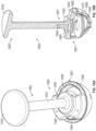
FIG. 6A illustrates an isometric view of atool assembly 600, in accordance with at least one example of this disclosure.FIG. 6B illustrates an isometric view of atool assembly 600, in accordance with at least one example of this disclosure.FIGS. 6A and6B are discussed below concurrently. - The
tool assembly 600 can include aremoval tool 602 and afaceplate 604. Animplant 601 can include anouter shell 606 and aliner 608. Thefaceplate 604 can include a bore 609 (such as a central bore) and an outer ring 611. Theremoval tool 602 can include ashaft 612 and ahandle 613. Also shown inFIG. 6A is an adhesive 605 and orientation indicators Proximal and Distal. Also shown inFIG. 6B are axis A, Forces F1, Force F2, and torque T. - The outer ring 611 of the
faceplate 604 can be configured to engage theshell 606 and can include arms connecting the outer ring 611 to a collar including thebore 609 where the bore is configured to receive theshaft 609 therein for coupling theshaft 612 to the faceplate, such as through a threaded engagement. - The
shaft 612 can extend substantially along the axis A and thehandle 613 can be connected to a proximal portion of theshaft 612. A distal portion of theshaft 612 can be configured for insertion into theliner 606 and to be secured to theliner 606 using the adhesive 605. The adhesive 605 can be a resin, composite filling, or the like. - There is described the operation of the assembly where, the
liner 606 can be lavaged and dried. Thefaceplate 604 can be secured to theshell 606. Either before or after securing the faceplate, the adhesive 605 can be applied to a nadir or low point (apex from an inverted perspective) of theliner 606. Theshaft 612 can be inserted into thebore 609 and secured to thefaceplate 604 and can be positioned to contact the adhesive 605. - The adhesive 605 can then be cured or allowed to set to secure the
shaft 612 of theremoval tool 602 to theliner 608. Thehandle 613 of theremoval tool 602 can be rotated to apply the torque T to theshaft 612, causing thefaceplate 604 to create the forces F1 applied to theshell 606 and causing theshaft 612 to apply the force F2 to theliner 608 through the adhesive 605. The force F2 can causeshaft 612 to separate theliner 608 from theshell 606 of theimplant 601. -
FIG. 7 illustrates an isometric view of atool assembly 700, in accordance with at least one example of this disclosure. Thetool assembly 700 can include a suction and plunger system for assisting in removal of a liner from a shell of an implant. Any of the previously or later discussed tool assemblies can include such components. - The
tool assembly 700 can include afaceplate 704, a tamp 707, andsuction conduits faceplate 704 can include abody 740 andarms 744a-744d. Animplant 701 can include anouter shell 706 and aliner 708. Theouter shell 706 can includenotches 719. Also shown inFIG. 7 are cross-sectional indicators 8-8 and orientation indicators Proximal and Distal. - The implant or
prosthesis 701 can be similar to those discussed above, such that theliner 708 can be located within theouter shell 706 and secured thereto through an interference fit. Theouter shell 706 can also include thenotches 719 extending distally from a proximal face of the shell. Thenotches 719 can be configured to receive feet of the arms 744 and can be configured to receive the tamp 707 therein. - The tamp 707 can be an elongate tool, similar to an impactor, configured to deliver a force to the
shell 706 through an opening of a patient. In some examples, the tamp 707 can be curved and in some examples, the tamp 707 can be substantially straight. - The
suction conduits suction conduit 715 can be connected to a port in thebody 740 and thesuction conduit 717 can be connected to a port of a plunger of the body 740 (as discussed further below). Each of thesuction conduits faceplate 704 for helping to remove theliner 708 from theshell 706. - As with other embodiments discussed above, the
arms 744a-744d can connect to thebody 740 and can extend radially outward therefrom. The arms 744 can be configured to engage the rim of theshell 706 and feet of the arms 744 can be configured to insert into thenotches 719. Further details and operation of thetool assembly 700 are discussed below with respect toFIGS. 8A-9 . -
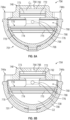
FIG. 8A illustrates a cross-sectional view across indicators 8-8 ofFIG. 7 of a portion of thetool assembly 700 in a first condition, in accordance with at least one example of this disclosure.FIG. 8B illustrates a cross-sectional view across indicators 8-8 ofFIG. 7 of a portion of thetool assembly 700 in a second condition, in accordance with at least one example of this disclosure.FIGS. 8A and 8B are discussed below concurrently. - The
tool assembly 700 can include thefaceplate 704, which can include thebody 740,arms 744a-744d, and aplunger 760. Theimplant 701 can include theouter shell 706 and theliner 708. Theouter shell 706 can includenotches 719. Thebody 740 can include apiston bore 762 and aconduit port 764. Theplunger 760 can include abody 766, aproximal piston 768, adistal piston 770, a proximal gasket 772 (in a proximal groove 773), a distal gasket 774 (in a distal groove 775), and abody port 776. Theliner 708 can include aninner wall 778. Also shown inFIGS. 8A and 8B are cavities C1 and C2 and orientation indicators Proximal and Distal. - The piston bore 762 of the
body 740 can be a bore extending proximally into the body and configured to receive theproximal piston 768 therein. Theconduit port 764 can be connected to the piston bore 762 such that the piston bore 762 is in fluid communication with the suction conduit 715 (ofFIG. 7 ). - The
body 766 of theplunger 760 can be a rigid or semi-rigid member connected to theproximal piston 768 and thedistal piston 770 to form theplunger 760. In some examples, thebody 766 can have a diameter smaller than a diameter of theproximal piston 768 and thedistal piston 770, which can help reduce weight and cost of theplunger 760. - The
proximal piston 768 can be connected to a proximal portion of thebody 768 and can be sized to move in and out of the piston bore 762. Theproximal piston 768 can have a shape substantially complimentary to the piston bore 762. Theproximal piston 768 can include theproximal groove 773, which can be a circumferential groove extending around a radially outer axial surface of theproximal piston 768. Theproximal groove 773 can be sized to receive theproximal gasket 772 such that theproximal piston 768 and theproximal gasket 772 can form a seal with the piston bore 768 while allowing proximal-to-distal (and reverse) movement of theproximal piston 768 with respect to thebody 740. - The
distal piston 770 can be connected to a distal portion of thebody 768 and can be sized to move with respect to theimplant 701. Thedistal piston 770 can include thedistal groove 775, which can be a circumferential groove extending around a radially outer axial surface of thedistal piston 770. Thedistal groove 775 can be sized to receive thedistal gasket 774. Thedistal piston 770 can have a shape, together with thedistal gasket 774, to engage theliner 708, such that thedistal piston 770 and thedistal gasket 774 can form a seal with theinner wall 778 of the liner. - There is also described the operation of the assembly, the
faceplate 704 can be inserted into an opening and can engage theouter shell 706, as discussed with respect toFIG. 7 , and the tamp 707 (ofFIG. 7 ) can be inserted into one of the notches 719 (ofFIG. 7 ). Either before or after securing thefaceplate 704 to the shell, theconduit 715 can be connected to thebody 740 and theconduit 717 can be connected to thebody 768 of theplunger 760. Suction can be applied through thesuction conduits 715 and 717 (shown inFIG. 7 ). Thesuction conduit 717 can apply a suction (or negative pressure) to thebody port 776 of thebody 768 of theplunger 760. Because thedistal piston 770 and thedistal gasket 774 can form a seal with theinner wall 778 of the liner, the negative pressure applied through thebody port 776 to the distal side of thedistal plunger 770 can create a negatively pressurized volume in the cavity C2 between thedistal plunger 770 and theinner wall 778 of theliner 708. The negative pressure of the cavity C2 can create a connection between thedistal plunger 770 and theinner wall 778, causing theliner 708 to move together with thedistal plunger 770. - Similarly, the
suction conduit 715 can apply a suction (or negative pressure) to the piston bore 762 via theconduit port 764 of thebody 740. Because theproximal piston 768 and theproximal gasket 772 can form a seal with the piston bore 768, the negative pressure within the cavity C1 between the piston bore and theproximal piston 768 can apply a distal-to-proximal force on theproximal piston 768, which can apply a similar (distal-to-proximal) force on thedistal piston 770 and theliner 708. - The
impactor 707 can then be impacted to transmit a force to theouter shell 706 where vibration of theouter shell 706 can cause theinner liner 708 to separate from theouter shell 706. Because theproximal piston 768 can move within the piston bore 768 and because thedistal piston 770 is connected to theinner wall 778 via suction pressure, once theliner 708 separates from theshell 706, the distal-to-proximal force applied to thepiston 760 and theliner 708 can cause thepiston 760 and theliner 708 to move proximally with respect to theouter shell 706 after, indicating to a physician or surgeon that no further impacts are necessary and that theliner 708 is ready to be extracted. -
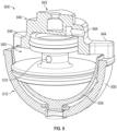
FIG. 9 illustrates a cross-sectional view of a portion of a tool assembly 900, in accordance with at least one example of this disclosure. The tool assembly 900 can include afaceplate 904. Thefaceplate 904 can include abody 940,arms 944, and aplunger 960. Thebody 940 can include aboss 942 and aconduit port 964. Theplunger 960 can include abody port 976. An implant 901 can include ashell 906 and aliner 908. Also shown inFIG. 9 are orientation indicators Proximal and Distal. - The tool assembly 900 can be similar to the
tool assembly 700 except that thebody 940 can include theboss 942 where theboss 942 can be configured to connect to a coupler of an impactor, such as thecoupler 114 of theimpactor 102 discussed above. Theboss 942 can be substantially rectangular (or square or the like) and can be complimentary to a bore of the coupler for releasable mating of the coupler to theboss 942 to secure thefaceplate 904 to the impactor. The tool assembly 900 can also differ in that theconduit port 964 can extend through a side of thebody 940 to help avoid interfering with a connection between theboss 942 and the coupler. Theplunger 960 can operate similarly to theplunger 760 discussed above. -
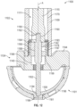
FIG. 10A illustrates a cross-sectional view of a portion of atool assembly 1000, in accordance with at least one example of this disclosure.FIG. 10B illustrates a cross-sectional view of a portion of thetool assembly 1000, in accordance with at least one example of this disclosure.FIGS. 10A and 10B are discussed below concurrently. - The
tool assembly 1000 can include animpactor 1002 and afaceplate 1004. Animplant 1001 can include ashell 1006 and aliner 1008. Theimpactor 1002 can include ashaft 1012 and astrike plate 1016. Theshaft 1012 can include aconduit port 1064. Thefaceplate 1004 can include abody 1040,arms 1044, and aplunger 1060. Theplunger 1060 can include abody port 1076. Also shown inFIGS. 10A and 10B are orientation indicators Proximal and Distal. - The
tool assembly 1000 can be similar to thetool assembly 700 discussed above except that theimpactor 1002 can be rigidly connected to thefaceplate 1004, which can simplify manufacturing of thetool assembly 1000. Further, theshaft 1012 can include theconduit port 1064, which can extend through theshaft 1012 and through thefaceplate 1004 to reach a proximal side of theplunger 1060. Theplunger 1060 can operate similarly to theplunger 760 discussed above. -
FIG. 11 illustrates an isometric view and a partial cross-sectional view of atool assembly 1100, in accordance with at least one example of this disclosure. Thetool assembly 1100 can include aremoval tool 1102 and afaceplate 1104. Animplant 1101 can include ashell 1106 and aliner 1108. Theremoval tool 1102 can include asleeve 1109, ahandle 1111, and adrill bit 1180. Thefaceplate 1104 can include abody 1140 andarms 1144. Also shown inFIG. 11 are axis A and orientation indicators Proximal and Distal. - The
sleeve 1109 can extend along the axis A and can be substantially hollow such that thesleeve 1109 can receive ashaft 1115 of thehandle 1111 therethrough. Theshaft 1115 can be releasably couplable to thedrill bit 1180 such that thedrill bit 1180 can extend through thesleeve 1109 along with theshaft 1115. Aknob 1113 can be secured to a proximal portion of ashaft 1115 of thehandle 1111. - The
arms 1144 can extend radially outward from thebody 1140 of the faceplate and can be configured to engage theshell 1106. Thebody 1140 can be couplable to thesleeve 1109, such as through a threaded connection. - In other embodiments, the
knob 1113 can be omitted and theshaft 1115 of thehandle 1111 can be connected to a driver for driving rotation of thedrill bit 1180. In yet other examples, theknob 1113 and theshaft 1115 can be configured to couple to a driver, such as an electric or pneumatic drill. - Further details and operation of the
tool assembly 1100 are discussed below with respect toFIG. 13 (with further reference toFIGS. 11 and12 ). -
FIG. 12 illustrates a cross-sectional view of thetool assembly 1100, in accordance with at least one example of this disclosure. Thetool assembly 1100 can be consistent with thetool assembly 1100 discussed above with respect toFIG. 11 ; further details are discussed with respect toFIG. 12 . - For example,
FIG. 12 shows that thefaceplate 1104 can include aboss 1142 that can have a threadedportion 1184, acentral bore 1186, and abushing bore 1188.FIG. 12 further shows that thesleeve 1109 can include acentral bore 1179 and a threadedportion 1188. Further, thehandle 1111 can include theshaft 1115, acoupling bore 1190, and aset screw bore 1192.FIG. 12 further shows that thetool assembly 1100 can include atap 1182 and abushing 1193. Thetap 1182 can include atip 1194 and atang 1196. Thebushing 1193 can include ashank bore 1195 and aset screw bore 1197. Also shown inFIG. 12 are axis A and orientation indicators Proximal and Distal. - The
boss 1142 can extend proximally from thebody 1140 and can include the threadedportion 1184, which can be radially outer threads of theboss 1142. The threadedportion 1184 can be insertable into thesleeve 1109 and can be threadably securable to the threadedportion 1188 of thesleeve 1109 to secure thefaceplate 1104 to thesleeve 1109. Thecentral bore 1186 can extend through thebody 1140 of the faceplate 1104 (and the boss 1142) substantially coaxially with the axis A. The bushing bore 1188 can extend into theboss 1142 from a proximal portion of theboss 1142. The busing bore 1188 can be sized to receive thebusing 1193 therein. - The
bushing 1193 can be connected to a distal portion of theshaft 1115 and can be configured to be a depth stop or depth limiter for thetap 1182. Thetap 1182 can be a tool configured to tap threads into a bore, such as by using thetip 1194. Thetang 1196 can be releasably couplable to thecoupling bore 1190 where theset screw bore 1192 can receive a set screw therein to secure thetang 1196 to thecoupling bore 1190 of theshaft 1115. Also, the set screw bore 1197 of the bushing can be used to releasably secure thebushing 1193 to thetap 1182. -
FIG. 13 illustrates a cross-sectional view of thetool assembly 1100, in accordance with at least one example of this disclosure. Thetool assembly 1100 can be consistent with thetool assembly 1100 discussed above with respect toFIGS. 11 and12 ; further details are discussed with respect toFIG. 13 . - For example,
FIG. 13 shows that thetool assembly 100 can include ahandle 1185, which can include aninner shaft 1187 and anouter shaft 1189. Theinner shaft 1187 can include a threadedportion 1191 and abolt bore 1155.FIG. 13 also shows abolt 1183, which can include ahead 1151 and a threadedportion 1153.FIG. 13 also shows that thecentral bore 1186 of thebody 1140 can include a distal threadedportion 1198. Also shown inFIG. 12 are axis A and orientation indicators Proximal and Distal. - The
handle 1185 can be a tool insertable into thesleeve 1109 to separate theliner 1108 from theshell 1106. Theouter shaft 1189 can have a diameter similar to thecentral bore 1179 of thesleeve 1109 to limit non-rotational and non-axial movement of thehandle 1185 within the sleeve with respect to the axis A. Theouter shaft 1189 can connect to a knob (similar to the knob 1113) and/or a driver and a proximal portion of theshaft 1189. The threadedportion 1191 of theinner shaft 1187 can threadably couple to the threadedportion 1198 of thefaceplate 1104 to secure thehandle 1185 of thefaceplate 1104. - The
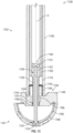
bolt 1183 can be securable to theliner 1108 for separation of theliner 1108 from theshell 1106. Thehead 1151 can be similar to a head of a bolt and can be sized to engage a proximal radial surface of theinner shaft 1187 of thehandle 1185. The threadedportion 1153 can be sized and shaped to threadably engage the tapped bore 1181 to secure thebolt 1183 to theliner 1108. Thebolt 1183 can be sized to extend through the bolt bore 1155 of theinner shaft 1187 and can be rotatable therein (in non-threaded engagement) and translatable with respect thereto. - There is also described the operation of the tool assembly, when it is desired to remove the
liner 1108 from theshell 1106, an opening can be created in the patient and thefaceplate 1104 can be positioned such that thearms 1144 contact theouter shell 1106. Thesleeve 1109 can then be secured to thefaceplate 1104 and thedrill bit 1180 and theshaft 1115 can be inserted through thesleeve 1109 to engage theliner 1108. The knob 113 can be rotated to rotate theshaft 1115 and thedrill bit 1180 to create thebore 1181 in the sleeve. In some examples, a driver can be used to rotate theshaft 1115. - After a drilling operation has been performed, the drill bit (1180 of
FIG. 11 ) can be disconnected from theshaft 1115 by loosening a set screw from engaging thedrill bit 1180. Thetap 1182 can then be secured to theshaft 1115 such as by using the set screw. In other examples, other coupling interfaces (such as a chuck or collar) can be used. Thebushing 1193 can be secured to a shank of thetap 1182 such as by using a set screw within thebore 1197 to engage thetap 1182. (Thebushing 1193 can also be used with the drill bit 1180). Theshaft 1115 can then be inserted into thecentral bore 1179 of thesleeve 1109 until thetip 1194 of the tap engages thebore 1181. Theknob 1113 can be rotated about the axis A to tap thebore 1181. A distal depth of thetip 1194 can be limited by contact between thebushing 1193 and aradial face 1199 formed by thecentral bore 1186 and thebushing bore 1188. Different sized bushings can be used adjust a tapping depth (or drilling depth-when using the drill bit 1180), allowing theremoval tool 1102 to be used with implants of various sizes and shapes. When tapping of thebore 1181 is complete, theshaft 1115,bushing 1193 andtap 1182 can be removed from thesleeve 1109. - Following removal of the
tap 1182, thehandle 1185 can be inserted into thesleeve 1109 and theinner shaft 1187 can be threaded into the threadedportion 1191 of thecentral bore 1186 of thefaceplate 1104 to secure thehandle 1185 to thefaceplate 1104. Then, thebolt 1183 can be inserted through the bolt bore 1155 of theinner shaft 1187 and thebolt 1183 can be threaded into the tapped bore 1181 to secure thebolt 1183 to thesleeve 1106. Thehandle 1185 can then be rotated to unthread theinner shaft 1187 from the threadedportion 1198 of the faceplate, which can cause theinner shaft 1187 to engage thehead 1151 of thebolt 1183 to force thebolt 1183 proximally, forcing theliner 1108 proximally. A reaction force can be applied by theinner shaft 1187 to thefaceplate 1104 and to theouter shell 1106 such that the proximal force applied to theliner 1108 and the distal force applied to theshell 1106 substantially cancel, which can help avoid disrupting a connection between theshell 1106 and an acetabulum of the patient. Theliner 1108 can be forced proximally until it separates from theshell 1106 allowing theliner 1108 to be removed from theshell 1106. -
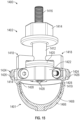
FIG. 14 illustrates an isometric view of atool assembly 1400, in accordance with at least one example of this disclosure.FIG. 15 illustrates a isometric view and a partial cross-sectional view of thetool assembly 1400, in accordance with at least one example of this disclosure.FIGS. 14 and15 are discussed below concurrently. - The
tool assembly 1400 can include aremoval tool 1402. An implant can include ashell 1406 and aliner 1408. Theremoval tool 1402 can include abody 1412, anut 1414, arod 1416,arms 1418, aflange 1420, aconnector 1422, andfasteners 1424. Theconnectors 1422 can formgaps 1426. Thearms 1418 can includeprojections 1428. Theshell 1406 can includenotches 1419. Also shown inFIGS. 14 and15 are orientation indicators Proximal and Distal. - The
nut 1414 can be connected to a proximal portion of thebody 1412 and theflange 1420 can connect to a distal portion of thebody 1412. Thenut 1414 can be threadably engaged with therod 1416, which can be a threaded rod secured to theconnector 1422. Thearms 1418 can be secured to theconnector 1422 throughfasteners 1424 such that thearms 1418 are pivotable about thefasteners 1424 with respect to theconnector 1422. Theprojections 1428 can be sized and shaped for insertion into thenotches 1419 between theshell 1406 and theliner 1408. - In operation, the
nut 1414 can be rotated about therod 1416 to cause thebody 1412 and theflange 1420 to translate proximally. As theflange 1420 moves proximally, the arms pivot about thefasteners 1424, causing theprojections 1428 to move radially inward to engage theliner 1408 and eventually deform theliner 1408 to separate the liner from theshell 1406. -
FIG. 16 illustrates a cross-sectional view of aliner 1608 of a tool assembly, in accordance with at least one example of this disclosure. Theliner 1608 can include aninner wall 1678, aremoval section 1683 and a tappedbore 1681. The tapped bore 1681 can be configured tot receive a bolt for removal of theliner 1608 from a shell (such as discussed with respect toFIGS. 11-13 . Theliner 1608 can include theremoval portion 1683 which can be drilled through or punched out to expose the tappedbore 1681, which can reduce drilling and tapping operations performed on theliner 1608 for extraction of theliner 1608 from a shell. -
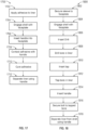
FIG. 17 a flow schematic of a method which does not form part of the claimed invention. Themethod 1700 can be a method of removing a liner from an outer shell of an implant using an adhesive and a removal tool. The steps or operations of themethod 1700 are illustrated in a particular order for convenience and clarity; many of the discussed operations can be performed in a different sequence or in parallel without materially impacting other operations. Themethod 1700 as discussed includes operations performed by multiple different actors, devices, and/or systems. It is understood that subsets of the operations discussed in themethod 1700 can be attributable to a single actor, device, or system could be considered a separate standalone process or method. - The
method 1700 can be begin atstep 1702 where an adhesive can be applied to an apex of the liner. Atstep 1704, a faceplate can be engaged with the shell. Atstep 1706, a handle can be inserted through a center of the faceplate. Atstep 1708, the distal end of the handle can contact the adhesive and atstep 1710 the adhesive can be cured or allowed to set to secure the handle to the liner. Atstep 1712, the handle can be rotated to separate the liner from the shell of the prosthesis or implant. In some examples, the liner can be lavaged and dried prior to applying the adhesive to the liner. - For example, the
liner 606 can be lavaged and dried. Thefaceplate 604 can be secured to theshell 606. Either before or after securing the faceplate, the adhesive 605 can be applied to a nadir or low point (apex from an inverted perspective) of theliner 606. Theshaft 612 can be inserted into thebore 609 and secured to thefaceplate 604 and can be positioned to contact the adhesive 605. The adhesive 605 can be cured or allowed to set to secure theshaft 612 of the removal tool 6 to theliner 606. Thehandle 613 of theremoval tool 602 can be rotated to apply the torque T to theshaft 612, causing the faceplate to create the forces F1 applied to theshell 606 and causing theshaft 612 to apply the force F2 to theliner 606 through the adhesive 605. The force F2 can causeshaft 612 to separate theliner 606 from theshell 608 of theimplant 601. -
FIG. 18 a flow schematic of a method which does not form part of the claimed invention. Themethod 1800 can be a method of removing a liner from an outer shell of an implant using a removal tool. Themethod 1800 can be begin atstep 1802 where a sleeve of a tool assembly can be secured to a faceplate of the tool assembly. For example, thesleeve 1109 can be secured to the faceplate 1104 (such as via the boss 1142). Atstep 1804, a faceplate can be engaged with the shell. For example, thefaceplate 1804 can be engaged with theshell 1106. - At
step 1806, a drill can be inserted through a central bore of the sleeve and through a central bore of the faceplate. For example, thedrill bit 1180 can be inserted through thecentral bore 1179 of thesleeve 1109 and through thecentral bore 1186 of the faceplate. Atstep 1808, a bore can be drilled in the liner using the drill. For example, thebore 1181 can be drilled in theliner 1106 using thedrill bit 1180. - At
step 1810, a tap can be inserted through the central bore of the sleeve and through the central bore of thefaceplate 1104. For example, thetap 1182 can be inserted through thecentral bore 1179 of thesleeve 1109 and through thecentral bore 1186 of thefaceplate 1104. Atstep 1812, the bore in the liner can be tapped using the tap. For example, thebore 1181 can be tapped in theliner 1108 using thetap 1182. Atstep 1814, thehandle 1185 can be inserted through thecentral bore 1179 of thesleeve 1109 and thehandle 1185 can be secured to thecentral bore 1186 of thefaceplate 1104. Atstep 1816, a bolt can be inserted through the handle and secured to the tapped bore. For example, thebolt 1183 can be inserted through thehandle 1185 and thebolt 1183 can be secured to the tapped bore 1181 of theliner 1108. Atstep 1818, the handle can be rotated to separate the liner from the shell of the prosthesis. For example, thehandle 1185 can be rotated to separate theliner 1108 from theshell 1106. - The above detailed description includes references to the accompanying drawings, which form a part of the detailed description. The drawings show, by way of illustration, specific embodiments in which the invention can be practiced. These embodiments are also referred to herein as "examples." Such examples can include elements in addition to those shown or described. However, the present inventors also contemplate examples in which only those elements shown or described are provided. Moreover, the present inventors also contemplate examples using any combination or permutation of those elements shown or described (or one or more aspects thereof), either with respect to a particular example (or one or more aspects thereof), or with respect to other examples (or one or more aspects thereof) shown or described herein.
- In this document, the terms "a" or "an" are used, as is common in patent documents, to include one or more than one, independent of any other instances or usages of "at least one" or "one or more." In this document, the term "or" is used to refer to a nonexclusive or, such that "A or B" includes "A but not B," "B but not A," and "A and B," unless otherwise indicated. In this document, the terms "including" and "in which" are used as the plain-English equivalents of the respective terms "comprising" and "wherein." Also, in the following claims, the terms "including" and "comprising" are open-ended, that is, a system, device, article, composition, formulation, or process that includes elements in addition to those listed after such a term in a claim are still deemed to fall within the scope of that claim. Moreover, in the following claims, the terms "first," "second," and "third," etc. are used merely as labels, and are not intended to impose numerical requirements on their objects.
- The above description is intended to be illustrative, and not restrictive. For example, the above-described examples (or one or more aspects thereof) may be used in combination with each other. Other embodiments can be used, such as by one of ordinary skill in the art upon reviewing the above description. The Abstract is provided to comply with 37 C.F.R. §1.72(b), to allow the reader to quickly ascertain the nature of the technical disclosure. It is submitted with the understanding that it will not be used to interpret or limit the scope or meaning of the claims. Also, in the above Detailed Description, various features may be grouped together to streamline the disclosure. This should not be interpreted as intending that an unclaimed disclosed feature is essential to any claim. Rather, inventive subject matter may lie in less than all features of a particular disclosed embodiment. Thus, the following claims are hereby incorporated into the Detailed Description as examples or embodiments, with each claim standing on its own as a separate embodiment, and it is contemplated that such embodiments can be combined with each other in various combinations or permutations. The scope of the invention should be determined with reference to the appended claims.
Claims (14)
- A tool assembly (100, 400, 500, 600,...) for extracting a liner (108) from a prosthesis (101), the tool comprising:an impactor (102) configured to receive and transmit a force, the impactor comprising:a handle (110) extending along a longitudinal axis (A) and configured to be impacted on a proximal portion of the handle;a shaft (112) connected to a distal portion of the handle and extending distally therefrom along the longitudinal axis; anda coupler (114) connected to a distal portion of the shaft, characterized in that the coupler includes a mating interface comprising a magnet (136); anda faceplate (104) configured to deliver the force from the impactor to the prosthesis, the faceplate comprising:a plurality of arms (144) engageable with an outer shell (106) of the prosthesis; anda boss (142) releasably couplable to the mating interface, the magnet (136) located in the coupler, configured to attract the boss to releasably secure the faceplate to the impactor.
- The tool assembly (100) of claim 1, the handle (110) further comprising:
a balance bore (118) sized to position a center of gravity of the impactor distal of the handle. - The tool assembly (100) of claim 1 or claim 2, the mating interface of the coupler (114) further comprising:a coupler bore (130) configured to receive the boss (142) therein; anda magnet bore (132) adjacent the coupler bore, the magnet (136) secured within the magnet bore adjacent the coupler bore.
- The tool assembly (100) of claim 3, wherein the magnet (136) is spaced from the coupler bore (130) within the magnet bore (132) such that the magnet magnetically attracts the boss (142) to motivate the boss to enter the coupler bore and is spaced away from the boss when the boss is inserted fully into the coupler bore.
- The tool assembly (100) of any of claims 1-4, the handle (110) further comprising:
a handle bore (120) extending proximally into the handle from the distal portion of the handle, the shaft (112) extending into the handle bore to secure the shaft to the handle. - The tool assembly (100) of claim 5, the coupler (114) further comprising:
a shaft bore extending distally into the coupler from a proximal portion of the coupler, the shaft extending into the shaft bore to secure the shaft to the coupler. - The tool assembly (100) of claim 6 wherein the handle is welded to the shaft near the shaft bore (134) and wherein the coupler is welded to the shaft near the shaft bore (134).
- The tool assembly (100) of claim 7 wherein the handle (102) includes a handle stop (124) engaged with the shaft (112) within the handle bore (120) that is configured to transmit force to the shaft (112) from the handle stop to reduce fatigue on the weld between the handle and the shaft, and wherein the shaft bore (134) includes a coupler stop (131) engaged with the shaft (112) within the shaft bore (134) that is configured to transmit force from the shaft (112) to the coupler (116) through the coupler stop (131) to reduce fatigue on the weld between the coupler and the shaft.
- The tool assembly (100) of claim 6, wherein the boss has a substantially rectangular prism shape and wherein the coupler bore has a substantially rectangular shape complimentary to the substantially rectangular prism shape of the boss.
- The tool assembly of any of claims 1-9, further comprising:
a strike plate (116) secured to a proximal portion of the handle. - The tool assembly (100) of any of claims 1-10, the faceplate further comprising:
a body (140) supporting the boss and the plurality of arms, the plurality of arms extending radially outward from the body and the boss extending proximally from the body. - The tool assembly of claim 11, each of the plurality of arms further comprising:
an extension (146) extending distally from the arm and including a distal surface (148) configured to contact the outer shell of the prosthesis and configured to deliver the force thereto. - The tool assembly of claim 12, each of the plurality of arms further comprising:
a foot (150) extending distally from the distal face, the foot insertable into a notch of the outer shell to limit rotation of the faceplate with respect to the outer shell when the foot is positioned within the notch. - The tool assembly of claim 12, wherein the body (140) includes a distal surface (154), the distal surfaces (148, 154) of the extension (146) and the body (140) together defining a recess, so that in use, vibrations in the shell caused by the delivered force cause the liner to separate from the shell and move proximally into the recess.
Applications Claiming Priority (2)
| Application Number | Priority Date | Filing Date | Title |
|---|---|---|---|
| US201862688839P | 2018-06-22 | 2018-06-22 | |
| PCT/US2019/038474 WO2019246523A1 (en) | 2018-06-22 | 2019-06-21 | Acetabular liner extraction |
Publications (2)
| Publication Number | Publication Date |
|---|---|
| EP3810039A1 EP3810039A1 (en) | 2021-04-28 |
| EP3810039B1 true EP3810039B1 (en) | 2023-09-06 |
Family
ID=67441585
Family Applications (1)
| Application Number | Title | Priority Date | Filing Date |
|---|---|---|---|
| EP19745341.8A Active EP3810039B1 (en) | 2018-06-22 | 2019-06-21 | Acetabular liner extraction |
Country Status (4)
| Country | Link |
|---|---|
| US (2) | US11452620B2 (en) |
| EP (1) | EP3810039B1 (en) |
| CN (1) | CN112334094B (en) |
| WO (1) | WO2019246523A1 (en) |
Families Citing this family (9)
| Publication number | Priority date | Publication date | Assignee | Title |
|---|---|---|---|---|
| CN112334094B (en) | 2018-06-22 | 2024-08-30 | 捷迈有限公司 | Acetabular liner removal |
| US12605258B2 (en) | 2020-09-18 | 2026-04-21 | Globus Medical, Inc. | Hip arthroplasty implants |
| GB202020305D0 (en) * | 2020-12-21 | 2021-02-03 | Depuy Ireland Ultd Co | Improvements in and relating to surgical instruments, systems and methods |
| US20230181337A1 (en) * | 2021-12-15 | 2023-06-15 | Encore Medical, L.P. (D/B/A Djo Surgical) | Device for disassembling implant systems |
| EP4447826A2 (en) * | 2021-12-18 | 2024-10-23 | Richard Marks | Metatarsal arthroplasty devices and systems |
| JP7635293B2 (en) * | 2022-04-27 | 2025-02-25 | グローバス メディカル インコーポレイティッド | Hip Arthroplasty Implants |
| CN114869550B (en) * | 2022-05-31 | 2024-09-24 | 杭州柳叶刀机器人有限公司 | Guide knocking cap for joint replacement and prosthesis knocking device |
| US20240016626A1 (en) * | 2022-07-15 | 2024-01-18 | Joint Development, Llc | Hard liner removal instrument |
| CN118436461B (en) * | 2024-07-08 | 2024-10-22 | 北京爱康宜诚医疗器材有限公司 | Acetabular cup extraction device |
Family Cites Families (15)
| Publication number | Priority date | Publication date | Assignee | Title |
|---|---|---|---|---|
| US6022357A (en) * | 1997-03-03 | 2000-02-08 | Aesculap Ag & Co. Kg | Surgical instrument |
| GB0100199D0 (en) * | 2001-01-05 | 2001-02-14 | Mcminn Derek J W | Hip prosthesis |
| US6916342B2 (en) * | 2002-04-01 | 2005-07-12 | Smith & Nephew, Inc. | Liner assembly for prosthetic components |
| US7931656B2 (en) * | 2004-01-05 | 2011-04-26 | Paramount Medical Instruments, L.L.C. | Acetabular shell impactor |
| US7927376B2 (en) * | 2005-06-30 | 2011-04-19 | Depuy Products, Inc. | Expandable acetabular liner extraction device, cup assembly and associated method |
| DE102008049661A1 (en) * | 2008-09-30 | 2010-04-01 | Smith & Nephew Orthopaedics Ag | Instrument for handling a joint component |
| US9005213B2 (en) * | 2012-11-16 | 2015-04-14 | DePuy Synthes Products, Inc. | Controlled force surgical implant impaction instrument |
| US20140228854A1 (en) * | 2013-02-08 | 2014-08-14 | Biomet Manufacturing Corporation | Apparatus And Method For Positioning A Prosthesis |
| DE102013009196A1 (en) * | 2013-06-03 | 2014-12-04 | Otto Bock Healthcare Gmbh | Prosthesis liner and prosthetic socket system with prosthetic liner and prosthetic socket |
| US10813774B2 (en) * | 2014-03-07 | 2020-10-27 | Biomet Manufacturing, Llc | Subject contacting plate |
| US10327916B2 (en) * | 2014-07-03 | 2019-06-25 | Howmedica Osteonics Corp. | Impact absorbing pad |
| US20160213492A1 (en) * | 2015-01-27 | 2016-07-28 | Trigon International Corporation | Impactor adaptor and screw assembly |
| WO2016187305A1 (en) * | 2015-05-18 | 2016-11-24 | Little Engine, LLC | Method and apparatus for extraction of medical implants |
| US9931213B2 (en) * | 2015-09-03 | 2018-04-03 | Muthana Sartawi | Acetabular cup and insertion handle |
| CN112334094B (en) | 2018-06-22 | 2024-08-30 | 捷迈有限公司 | Acetabular liner removal |
-
2019
- 2019-06-21 CN CN201980041539.2A patent/CN112334094B/en active Active
- 2019-06-21 EP EP19745341.8A patent/EP3810039B1/en active Active
- 2019-06-21 US US16/448,623 patent/US11452620B2/en active Active
- 2019-06-21 WO PCT/US2019/038474 patent/WO2019246523A1/en not_active Ceased
-
2022
- 2022-08-22 US US17/892,850 patent/US12491091B2/en active Active
Also Published As
| Publication number | Publication date |
|---|---|
| US11452620B2 (en) | 2022-09-27 |
| US20190388243A1 (en) | 2019-12-26 |
| CN112334094B (en) | 2024-08-30 |
| US20220401231A1 (en) | 2022-12-22 |
| WO2019246523A1 (en) | 2019-12-26 |
| EP3810039A1 (en) | 2021-04-28 |
| US12491091B2 (en) | 2025-12-09 |
| CN112334094A (en) | 2021-02-05 |
Similar Documents
| Publication | Publication Date | Title |
|---|---|---|
| US12491091B2 (en) | Acetabular liner extraction | |
| US8876837B2 (en) | Method and apparatus for implanting a modular femoral hip | |
| US11612501B2 (en) | Hip and knee joint stem explant system and methods of using the same | |
| KR101422463B1 (en) | Method of producing a prosthetic hip cotyle | |
| EP2665447B1 (en) | Adapter for explant system | |
| US10596011B2 (en) | Orthopaedic surgical instrument and method for positioning an acetabular prosthetic component | |
| US5382251A (en) | Plug pulling method | |
| US5324297A (en) | Ultrasonic tool connector | |
| EP2732776B1 (en) | Surgical implant impaction instrument | |
| EP2953586B1 (en) | Apparatus for positioning a prosthesis | |
| CN112842614B (en) | Surgical tray, apparatus and method for implanting a hip replacement prosthesis | |
| EP2777625B1 (en) | Prosthetic component | |
| WO2025151759A1 (en) | Taper connection separation device and method | |
| WO2020183129A1 (en) | Impactor device | |
| HK40043057A (en) | Surgical trays, instruments and methods for implanting a hip replacement prosthesis | |
| HK1138753B (en) | Cotyle comprising a sterile interface |
Legal Events
| Date | Code | Title | Description |
|---|---|---|---|
| STAA | Information on the status of an ep patent application or granted ep patent |
Free format text: STATUS: UNKNOWN |
|
| STAA | Information on the status of an ep patent application or granted ep patent |
Free format text: STATUS: THE INTERNATIONAL PUBLICATION HAS BEEN MADE |
|
| PUAI | Public reference made under article 153(3) epc to a published international application that has entered the european phase |
Free format text: ORIGINAL CODE: 0009012 |
|
| STAA | Information on the status of an ep patent application or granted ep patent |
Free format text: STATUS: REQUEST FOR EXAMINATION WAS MADE |
|
| 17P | Request for examination filed |
Effective date: 20210121 |
|
| AK | Designated contracting states |
Kind code of ref document: A1 Designated state(s): AL AT BE BG CH CY CZ DE DK EE ES FI FR GB GR HR HU IE IS IT LI LT LU LV MC MK MT NL NO PL PT RO RS SE SI SK SM TR |
|
| AX | Request for extension of the european patent |
Extension state: BA ME |
|
| DAV | Request for validation of the european patent (deleted) | ||
| DAX | Request for extension of the european patent (deleted) | ||
| STAA | Information on the status of an ep patent application or granted ep patent |
Free format text: STATUS: EXAMINATION IS IN PROGRESS |
|
| 17Q | First examination report despatched |
Effective date: 20220318 |
|
| GRAP | Despatch of communication of intention to grant a patent |
Free format text: ORIGINAL CODE: EPIDOSNIGR1 |
|
| STAA | Information on the status of an ep patent application or granted ep patent |
Free format text: STATUS: GRANT OF PATENT IS INTENDED |
|
| INTG | Intention to grant announced |
Effective date: 20230323 |
|
| GRAS | Grant fee paid |
Free format text: ORIGINAL CODE: EPIDOSNIGR3 |
|
| GRAA | (expected) grant |
Free format text: ORIGINAL CODE: 0009210 |
|
| STAA | Information on the status of an ep patent application or granted ep patent |
Free format text: STATUS: THE PATENT HAS BEEN GRANTED |
|
| AK | Designated contracting states |
Kind code of ref document: B1 Designated state(s): AL AT BE BG CH CY CZ DE DK EE ES FI FR GB GR HR HU IE IS IT LI LT LU LV MC MK MT NL NO PL PT RO RS SE SI SK SM TR |
|
| REG | Reference to a national code |
Ref country code: GB Ref legal event code: FG4D |
|
| REG | Reference to a national code |
Ref country code: CH Ref legal event code: EP |
|
| REG | Reference to a national code |
Ref country code: DE Ref legal event code: R096 Ref document number: 602019036813 Country of ref document: DE |
|
| REG | Reference to a national code |
Ref country code: IE Ref legal event code: FG4D |
|
| REG | Reference to a national code |
Ref country code: LT Ref legal event code: MG9D |
|
| REG | Reference to a national code |
Ref country code: NL Ref legal event code: MP Effective date: 20230906 |
|
| PG25 | Lapsed in a contracting state [announced via postgrant information from national office to epo] |
Ref country code: GR Free format text: LAPSE BECAUSE OF FAILURE TO SUBMIT A TRANSLATION OF THE DESCRIPTION OR TO PAY THE FEE WITHIN THE PRESCRIBED TIME-LIMIT Effective date: 20231207 |
|
| PG25 | Lapsed in a contracting state [announced via postgrant information from national office to epo] |
Ref country code: SE Free format text: LAPSE BECAUSE OF FAILURE TO SUBMIT A TRANSLATION OF THE DESCRIPTION OR TO PAY THE FEE WITHIN THE PRESCRIBED TIME-LIMIT Effective date: 20230906 Ref country code: RS Free format text: LAPSE BECAUSE OF FAILURE TO SUBMIT A TRANSLATION OF THE DESCRIPTION OR TO PAY THE FEE WITHIN THE PRESCRIBED TIME-LIMIT Effective date: 20230906 Ref country code: NO Free format text: LAPSE BECAUSE OF FAILURE TO SUBMIT A TRANSLATION OF THE DESCRIPTION OR TO PAY THE FEE WITHIN THE PRESCRIBED TIME-LIMIT Effective date: 20231206 Ref country code: LV Free format text: LAPSE BECAUSE OF FAILURE TO SUBMIT A TRANSLATION OF THE DESCRIPTION OR TO PAY THE FEE WITHIN THE PRESCRIBED TIME-LIMIT Effective date: 20230906 Ref country code: LT Free format text: LAPSE BECAUSE OF FAILURE TO SUBMIT A TRANSLATION OF THE DESCRIPTION OR TO PAY THE FEE WITHIN THE PRESCRIBED TIME-LIMIT Effective date: 20230906 Ref country code: HR Free format text: LAPSE BECAUSE OF FAILURE TO SUBMIT A TRANSLATION OF THE DESCRIPTION OR TO PAY THE FEE WITHIN THE PRESCRIBED TIME-LIMIT Effective date: 20230906 Ref country code: GR Free format text: LAPSE BECAUSE OF FAILURE TO SUBMIT A TRANSLATION OF THE DESCRIPTION OR TO PAY THE FEE WITHIN THE PRESCRIBED TIME-LIMIT Effective date: 20231207 Ref country code: FI Free format text: LAPSE BECAUSE OF FAILURE TO SUBMIT A TRANSLATION OF THE DESCRIPTION OR TO PAY THE FEE WITHIN THE PRESCRIBED TIME-LIMIT Effective date: 20230906 |
|
| REG | Reference to a national code |
Ref country code: AT Ref legal event code: MK05 Ref document number: 1607516 Country of ref document: AT Kind code of ref document: T Effective date: 20230906 |
|
| PG25 | Lapsed in a contracting state [announced via postgrant information from national office to epo] |
Ref country code: NL Free format text: LAPSE BECAUSE OF FAILURE TO SUBMIT A TRANSLATION OF THE DESCRIPTION OR TO PAY THE FEE WITHIN THE PRESCRIBED TIME-LIMIT Effective date: 20230906 |
|
| PG25 | Lapsed in a contracting state [announced via postgrant information from national office to epo] |
Ref country code: IS Free format text: LAPSE BECAUSE OF FAILURE TO SUBMIT A TRANSLATION OF THE DESCRIPTION OR TO PAY THE FEE WITHIN THE PRESCRIBED TIME-LIMIT Effective date: 20240106 |
|
| PG25 | Lapsed in a contracting state [announced via postgrant information from national office to epo] |
Ref country code: AT Free format text: LAPSE BECAUSE OF FAILURE TO SUBMIT A TRANSLATION OF THE DESCRIPTION OR TO PAY THE FEE WITHIN THE PRESCRIBED TIME-LIMIT Effective date: 20230906 |
|
| PG25 | Lapsed in a contracting state [announced via postgrant information from national office to epo] |
Ref country code: ES Free format text: LAPSE BECAUSE OF FAILURE TO SUBMIT A TRANSLATION OF THE DESCRIPTION OR TO PAY THE FEE WITHIN THE PRESCRIBED TIME-LIMIT Effective date: 20230906 |
|
| PG25 | Lapsed in a contracting state [announced via postgrant information from national office to epo] |
Ref country code: SM Free format text: LAPSE BECAUSE OF FAILURE TO SUBMIT A TRANSLATION OF THE DESCRIPTION OR TO PAY THE FEE WITHIN THE PRESCRIBED TIME-LIMIT Effective date: 20230906 Ref country code: RO Free format text: LAPSE BECAUSE OF FAILURE TO SUBMIT A TRANSLATION OF THE DESCRIPTION OR TO PAY THE FEE WITHIN THE PRESCRIBED TIME-LIMIT Effective date: 20230906 Ref country code: IS Free format text: LAPSE BECAUSE OF FAILURE TO SUBMIT A TRANSLATION OF THE DESCRIPTION OR TO PAY THE FEE WITHIN THE PRESCRIBED TIME-LIMIT Effective date: 20240106 Ref country code: ES Free format text: LAPSE BECAUSE OF FAILURE TO SUBMIT A TRANSLATION OF THE DESCRIPTION OR TO PAY THE FEE WITHIN THE PRESCRIBED TIME-LIMIT Effective date: 20230906 Ref country code: EE Free format text: LAPSE BECAUSE OF FAILURE TO SUBMIT A TRANSLATION OF THE DESCRIPTION OR TO PAY THE FEE WITHIN THE PRESCRIBED TIME-LIMIT Effective date: 20230906 Ref country code: CZ Free format text: LAPSE BECAUSE OF FAILURE TO SUBMIT A TRANSLATION OF THE DESCRIPTION OR TO PAY THE FEE WITHIN THE PRESCRIBED TIME-LIMIT Effective date: 20230906 Ref country code: AT Free format text: LAPSE BECAUSE OF FAILURE TO SUBMIT A TRANSLATION OF THE DESCRIPTION OR TO PAY THE FEE WITHIN THE PRESCRIBED TIME-LIMIT Effective date: 20230906 Ref country code: SK Free format text: LAPSE BECAUSE OF FAILURE TO SUBMIT A TRANSLATION OF THE DESCRIPTION OR TO PAY THE FEE WITHIN THE PRESCRIBED TIME-LIMIT Effective date: 20230906 Ref country code: PT Free format text: LAPSE BECAUSE OF FAILURE TO SUBMIT A TRANSLATION OF THE DESCRIPTION OR TO PAY THE FEE WITHIN THE PRESCRIBED TIME-LIMIT Effective date: 20240108 |
|
| P01 | Opt-out of the competence of the unified patent court (upc) registered |
Effective date: 20240326 |
|
| PG25 | Lapsed in a contracting state [announced via postgrant information from national office to epo] |
Ref country code: PL Free format text: LAPSE BECAUSE OF FAILURE TO SUBMIT A TRANSLATION OF THE DESCRIPTION OR TO PAY THE FEE WITHIN THE PRESCRIBED TIME-LIMIT Effective date: 20230906 Ref country code: IT Free format text: LAPSE BECAUSE OF FAILURE TO SUBMIT A TRANSLATION OF THE DESCRIPTION OR TO PAY THE FEE WITHIN THE PRESCRIBED TIME-LIMIT Effective date: 20230906 |
|
| REG | Reference to a national code |
Ref country code: DE Ref legal event code: R097 Ref document number: 602019036813 Country of ref document: DE |
|
| PG25 | Lapsed in a contracting state [announced via postgrant information from national office to epo] |
Ref country code: DK Free format text: LAPSE BECAUSE OF FAILURE TO SUBMIT A TRANSLATION OF THE DESCRIPTION OR TO PAY THE FEE WITHIN THE PRESCRIBED TIME-LIMIT Effective date: 20230906 |
|
| PLBE | No opposition filed within time limit |
Free format text: ORIGINAL CODE: 0009261 |
|
| STAA | Information on the status of an ep patent application or granted ep patent |
Free format text: STATUS: NO OPPOSITION FILED WITHIN TIME LIMIT |
|
| PG25 | Lapsed in a contracting state [announced via postgrant information from national office to epo] |
Ref country code: DK Free format text: LAPSE BECAUSE OF FAILURE TO SUBMIT A TRANSLATION OF THE DESCRIPTION OR TO PAY THE FEE WITHIN THE PRESCRIBED TIME-LIMIT Effective date: 20230906 Ref country code: SI Free format text: LAPSE BECAUSE OF FAILURE TO SUBMIT A TRANSLATION OF THE DESCRIPTION OR TO PAY THE FEE WITHIN THE PRESCRIBED TIME-LIMIT Effective date: 20230906 |
|
| 26N | No opposition filed |
Effective date: 20240607 |
|
| PG25 | Lapsed in a contracting state [announced via postgrant information from national office to epo] |
Ref country code: BG Free format text: LAPSE BECAUSE OF FAILURE TO SUBMIT A TRANSLATION OF THE DESCRIPTION OR TO PAY THE FEE WITHIN THE PRESCRIBED TIME-LIMIT Effective date: 20230906 |
|
| PG25 | Lapsed in a contracting state [announced via postgrant information from national office to epo] |
Ref country code: BG Free format text: LAPSE BECAUSE OF FAILURE TO SUBMIT A TRANSLATION OF THE DESCRIPTION OR TO PAY THE FEE WITHIN THE PRESCRIBED TIME-LIMIT Effective date: 20230906 |
|
| PG25 | Lapsed in a contracting state [announced via postgrant information from national office to epo] |
Ref country code: MC Free format text: LAPSE BECAUSE OF FAILURE TO SUBMIT A TRANSLATION OF THE DESCRIPTION OR TO PAY THE FEE WITHIN THE PRESCRIBED TIME-LIMIT Effective date: 20230906 |
|
| PG25 | Lapsed in a contracting state [announced via postgrant information from national office to epo] |
Ref country code: LU Free format text: LAPSE BECAUSE OF NON-PAYMENT OF DUE FEES Effective date: 20240621 |
|
| PG25 | Lapsed in a contracting state [announced via postgrant information from national office to epo] |
Ref country code: IE Free format text: LAPSE BECAUSE OF NON-PAYMENT OF DUE FEES Effective date: 20240621 |
|
| PG25 | Lapsed in a contracting state [announced via postgrant information from national office to epo] |
Ref country code: BE Free format text: LAPSE BECAUSE OF NON-PAYMENT OF DUE FEES Effective date: 20240630 |
|
| REG | Reference to a national code |
Ref country code: BE Ref legal event code: MM Effective date: 20240630 |
|
| PGFP | Annual fee paid to national office [announced via postgrant information from national office to epo] |
Ref country code: DE Payment date: 20250512 Year of fee payment: 7 |
|
| PGFP | Annual fee paid to national office [announced via postgrant information from national office to epo] |
Ref country code: GB Payment date: 20250513 Year of fee payment: 7 |
|
| PGFP | Annual fee paid to national office [announced via postgrant information from national office to epo] |
Ref country code: FR Payment date: 20250509 Year of fee payment: 7 |
|
| PGFP | Annual fee paid to national office [announced via postgrant information from national office to epo] |
Ref country code: CH Payment date: 20250701 Year of fee payment: 7 |
|
| PG25 | Lapsed in a contracting state [announced via postgrant information from national office to epo] |
Ref country code: CY Free format text: LAPSE BECAUSE OF FAILURE TO SUBMIT A TRANSLATION OF THE DESCRIPTION OR TO PAY THE FEE WITHIN THE PRESCRIBED TIME-LIMIT; INVALID AB INITIO Effective date: 20190621 |
|
| PG25 | Lapsed in a contracting state [announced via postgrant information from national office to epo] |
Ref country code: HU Free format text: LAPSE BECAUSE OF FAILURE TO SUBMIT A TRANSLATION OF THE DESCRIPTION OR TO PAY THE FEE WITHIN THE PRESCRIBED TIME-LIMIT; INVALID AB INITIO Effective date: 20190621 |