EP3809739B1 - Monitoring in a 5g non-standalone architecture to determine bearer type - Google Patents
Monitoring in a 5g non-standalone architecture to determine bearer type Download PDFInfo
- Publication number
- EP3809739B1 EP3809739B1 EP20197777.4A EP20197777A EP3809739B1 EP 3809739 B1 EP3809739 B1 EP 3809739B1 EP 20197777 A EP20197777 A EP 20197777A EP 3809739 B1 EP3809739 B1 EP 3809739B1
- Authority
- EP
- European Patent Office
- Prior art keywords
- base stations
- gnodeb
- response message
- database
- bearer
- Prior art date
- Legal status (The legal status is an assumption and is not a legal conclusion. Google has not performed a legal analysis and makes no representation as to the accuracy of the status listed.)
- Active
Links
Images



Classifications
-
- H—ELECTRICITY
- H04—ELECTRIC COMMUNICATION TECHNIQUE
- H04W—WIRELESS COMMUNICATION NETWORKS
- H04W8/00—Network data management
- H04W8/30—Network data restoration; Network data reliability; Network data fault tolerance
-
- H—ELECTRICITY
- H04—ELECTRIC COMMUNICATION TECHNIQUE
- H04W—WIRELESS COMMUNICATION NETWORKS
- H04W24/00—Supervisory, monitoring or testing arrangements
- H04W24/08—Testing, supervising or monitoring using real traffic
-
- H—ELECTRICITY
- H04—ELECTRIC COMMUNICATION TECHNIQUE
- H04W—WIRELESS COMMUNICATION NETWORKS
- H04W24/00—Supervisory, monitoring or testing arrangements
- H04W24/04—Arrangements for maintaining operational condition
-
- H—ELECTRICITY
- H04—ELECTRIC COMMUNICATION TECHNIQUE
- H04W—WIRELESS COMMUNICATION NETWORKS
- H04W24/00—Supervisory, monitoring or testing arrangements
- H04W24/02—Arrangements for optimising operational condition
-
- H—ELECTRICITY
- H04—ELECTRIC COMMUNICATION TECHNIQUE
- H04W—WIRELESS COMMUNICATION NETWORKS
- H04W76/00—Connection management
- H04W76/10—Connection setup
- H04W76/11—Allocation or use of connection identifiers
-
- H—ELECTRICITY
- H04—ELECTRIC COMMUNICATION TECHNIQUE
- H04W—WIRELESS COMMUNICATION NETWORKS
- H04W88/00—Devices specially adapted for wireless communication networks, e.g. terminals, base stations or access point devices
- H04W88/18—Service support devices; Network management devices
-
- H—ELECTRICITY
- H04—ELECTRIC COMMUNICATION TECHNIQUE
- H04W—WIRELESS COMMUNICATION NETWORKS
- H04W92/00—Interfaces specially adapted for wireless communication networks
- H04W92/16—Interfaces between hierarchically similar devices
- H04W92/24—Interfaces between hierarchically similar devices between backbone network devices
Definitions
- the present disclosure generally relates to 5G networking. More particularly, the present disclosure relates to systems and methods for monitoring in a 5G Non-Standalone (NSA) architecture to determine user plane bearer type, including identification of whether a bearer is over a 4G radio network element (eNodeB) or a 5G radio network element (gNodeB).
- NSA 5G Non-Standalone
- 5G next-generation cellular network technology
- NSA Non-Standalone
- 5G-enabled devices connect to 5G frequencies for data-throughput improvements but still use 4G for non-data functions such as communication to the cell towers and servers. That is, the NSA mode that depends on the control plane of the existing 4G (LTE) network for control functions, while the 5G NR (New Radio) utilizes 5G features on the user plane.
- LTE Long Term Evolution
- 5G NR New Radio
- the user plane (sometimes known as the data plane, forwarding plane, carrier plane or bearer plane) carries the network user traffic, whereas the control plane carries signaling traffic.
- the 5G NR is a Radio Access Technology (RAT) for the 5G network, i.e., the global standard for the air interface of 5G networks.
- RAT Radio Access Technology
- Patent application EP 2 469 761 A1 describes a network monitoring system configured for 4G mobile systems.
- the present disclosure relates to systems and methods for monitoring in a 5G Non-Standalone (NSA) architecture to determine user plane bearer type, including identification of whether a bearer is over a 4G radio network element (eNodeB) or a 5G radio network element (gNodeB).
- NSA Non-Standalone
- This identification is utilized in a monitoring system for the mobile network, and it is based solely on monitoring messages over the S11 interface.
- the present disclosure includes a technique to identify gNodeB addresses in messages on the S11 interface.
- These addresses are stored in a database of known gNodeB's and utilized later to determine bearer type, i.e., if the address is in the database, the user plane includes a 5G NSA bearer; otherwise, the user plane includes a 4G bearer.
- the systems and methods can be implemented as instructions in a non-transitory computer-readable medium.
- the systems and methods can be a computer-implemented method.
- the systems and methods include a processing device for implementing the bearer type identification.
- the systems and methods include obtaining monitored messages between a Mobility Management Entity (MME) and a Serving Gateway (SGW) in a 5G Non-Standalone (NSA) system; detecting base stations that are gNodeB base stations based on the monitored messages; and storing the detected gNodeB base stations in a database of known gNodeB base stations in the 5G NSA system.
- MME Mobility Management Entity
- SGW Serving Gateway
- NSA Non-Standalone
- the systems and methods can further include identifying a bearer as utilizing 5G Radio Access Technology based on a presence of an address associated with the detected gNodeB base stations in the database of known gNodeB base stations.
- the systems and methods can further include identifying a bearer as utilizing 4G Radio Access Technology based on a lack of the presence of the address in the database of known gNodeB base stations.
- the detecting is based on a second Modify Bearer Request or Response message after a first Modify Bearer Request or Response message and a Create Session Request or Response message.
- the second Modify Bearer Request or Response message is one of i) without an eNodeB identifier and ii) with an eNodeB identifier from the corresponding Create Session Request or Response message, each indicating a new address associated with the second Modify Bearer Request or Response message is a gNodeB base station.
- the monitored messages can be associated with establishing tunnels with Tunnel Endpoint Identifiers (TEID) between the SGW and the base stations.
- the monitored messages can be obtained from an S11 control plane interface.
- the monitored messages can be obtained at the SGW.
- the systems and methods can further include providing the database of known gNodeB base stations to a monitoring system for use in the identification of the bearer type.
- the present disclosure relates to systems and methods for monitoring in a 5G Non-Standalone (NSA) architecture to determine user plane bearer type, including identification of whether a bearer is over a 4G radio network element (eNodeB) or a 5G radio network element (gNodeB).
- NSA Non-Standalone
- This identification is utilized in a monitoring system for the mobile network, and it is based solely on monitoring messages over the S11 interface.
- the present disclosure includes a technique to identify gNodeB addresses in messages on the S11 interface.
- These addresses are stored in a database of known gNodeB's and utilized later to determine bearer type, i.e., if the address is in the database, the user plane includes a 5G NSA bearer; otherwise, the user plane includes a 4G bearer.
- EPC Evolved Packet Core
- RAT Radio Access Technology
- NR New Radio which is the Radio Access Technology (RAT) for the 5G NSA Non-Standalone PGW Packet Data Network Gateway which provides from the UE to external packet data networks by being the point of exit and entry of traffic for the UE RAT Radio Access Technology SGW Serving Gateway which routes and forwards user data packets, while also acting as the mobility anchor for the UP during inter-eNodeB handovers and as the anchor for mobility between LTE and other 3GPP technologies (terminating S4 interface and relaying the traffic between 2G/3G systems and PGW) TEID Tunnel Endpoint Identifier UE User Equipment which is a user device connecting to the mobile network.
- RAT Radio Access Technology
- the present disclosure relates to systems and methods for monitoring in a 5G Non-Standalone (NSA) architecture to determine bearer type, including identification of whether a bearer is over a 4G radio network element (eNodeB) or a 5G radio network element (gNodeB).
- eNodeB 4G radio network element
- gNodeB 5G radio network element
- EPC Evolved Packet Core
- MME Mobility Management Entity
- SGW Serving GPRS Support Node
- the present disclosure is utilized in a user plane monitoring system for a mobile network, to enable identification of a bearer type in a data record in the user plane on the radio access technology (4G or 5G).
- the present disclosure describes systems and methods for detecting base stations that are gNodeB base stations based on Modify Bearer Requests on the S11 interface.
- the S11 messages can be monitored to detect IP addresses of gNodeBs for storing in a database to later use in identifying bearer types.
- the sequence of S11 messages can include a Create Session Request/Response and a first Modify Bearer Request/Response after the Create Session Request/Response.
- the IP address for the DL in the first Modify Bearer Request/Response is for an eNodeB since this is a 5G NSA system. It is determined that if there is a second Modify Bearer Request/Response with a new IP address for the DL that this new IP address for the DL identifies a gNodeB.
- FIG. 1 is a block diagram of select interfaces in a 5G NSA system 10.
- the 5G NSA system 10 includes an eNodeB 12, a gNodeB 14, an MME 16, and an SGW 18.
- a monitoring system 20 which can be a physical system interacting with the SGW 18, a method implemented on or with the SGW 18, computer-readable code executed on or with the SGW 18, etc.
- the monitoring system 20 is configured to capture data associated with the operation of the 5G NSA system 10. Such captured data is utilized by a network operator for various network operations, management, and billing purposes.
- the capture of user plane information is performed at or on the SGW 18, with the monitoring system 20.
- the monitoring system 20 can also capture control plane information for use with the user plane information.
- the control plane information can include RAT type, the network element, etc.
- the control plane information and the user plane information are captured and monitored by the monitoring system 20 for use by the network operator of the 5G NSA system 10 for various network management purposes.
- a control plane S11 interface allows a correlation between the control plane and the user plane.
- the RAT type (EUTRAN for 4G) and the 4G radio network element (eNodeB) are provided over the control plane S11 interface and can be included in user plane data records, such as in the monitoring system 20.
- a data record is a listing of data of user plane activity between a UE and an application server.
- the data record can be a Call Detail Record (CDR).
- CDR Call Detail Record
- the data record can provide subscriber information, network information, user plane information as the application, the exchanged data volumes, and the throughput in the downlink and uplink directions.
- the information of the RAT is important to capture for the network operator.
- the present disclosure relates, in part, to data records and 5G NR UP bearer identification.
- the core network and the protocols around the SGW 18 remain the same. There is no new information on the control plane S11 interface to identify if a bearer is done on a 4G radio network element (eNodeB 12) or a 5G radio network element (gNodeB 14). That is, there is no 5G indicator on the SGW.
- the RAT type remains the EUTRAN whatever the connected RAT
- a bearer refers to a path that user traffic takes in a network, such as between UE and a Packet Data Network Gateway (PGW).
- PGW Packet Data Network Gateway
- the S1-U (S1 user plane) bearer can be either 4G or 5G, and the present disclosure relates to the identification of an S1-U bearer between the SGW and the eNodeB 12 (4G radio equipment), or the gNodeB 14 (5G radio equipment). That is, the present disclosure provides a technique for how to identify the eNodeB 12 (4G radio equipment) and the gNodeB 14 (5G radio equipment) in the control plane signaling, via the S11 interface.
- a first approach to differentiate the S1-U bearers is to identify gNodeB elements in a topology file manually.
- the monitoring system 20 can declare any S1-U bearers from the identified gNodeB elements as using a 5G bearer while others are a 4G bearer.
- this approach requires constant updating for a network operator as new elements are constantly deployed (i.e., new gNodeBs are deployed regularly). This approach is administratively difficult to implement.
- S6a interface is a 4G mobile-related interface between the MME and the Home Subscriber Server (HSS) used for authentication, location, and service information.
- HSS Home Subscriber Server
- the present disclosure includes a technique to automatically identify a gNodeB and create an automatic topology to identify a 5G bearer.
- the technique relies on messages to determine the bearer type.
- the present disclosure can automatically identify the gNodeBs 14 (based on their address) and determine any bearers are 5G based on the address of the automatically identified gNodeBs 14 being present (indicating a 5G NSA bearer) or not present (indicating a 4G bearer).
- the S1-C interface (S1 control plane) is updated with a new message to change the user plane IP address and the TEID DL (@IP-U/TEID DL).
- the S11 interface there is no specific information to identify a @IP-U/TEID DL allocated for a gNodeB 14 or an eNodeB 12.
- the present disclosure includes a process to automatically identify the IP addresses of the gNodeBs 14 in the 5G NSA system 10. Once identified, each IP address of the gNodeBs 14 is added to a list. The list can be utilized by the monitoring system 20 to identify 5G bearers.
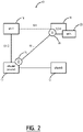
- FIG. 2 is a block diagram of select interfaces in the 4G system 10 for creating a session and for a first modified bearer.
- FIG. 3 is a block diagram of select interfaces in the 5G NSA system 10 for a second modified bearer.
- a @IP-U/TEID UL 22 is created at the SGW 18.
- the uplink user plane packets are sent from the eNodeB 12 to the SGW 18, via the @IP-U/TEID UL 22.
- the eNodeB 12 is identifier (as a master) with its eNodeB identifier (ID).
- a @IP-U/TEID DL 24 is created at the eNodeB 12.
- downlink and uplink user plane packets are sent between the SGW 18 to the eNodeB 12, via the @IP-U/TEID UL 22 and the @IP-U/TEID DL 24.
- the first modification is down for the @IP-U/TEID DL 24.
- a third step where there is a 5G bearer, there is a second modification of the bearer with a second request and a second response message, over the S11 interface, and a @IP-U/TEID DL 26 is allocated at the gNodeB 14.
- downlink and uplink user plane packets are sent between the SGW 18 to the gNodeB 14, via the @IP-U/TEID UL 22 and the @IP-U/TEID DL 26.
- the second modification switches to the gNodeB 14, from the eNodeB 12.
- the present disclosure is based in part on the detection of the second modification with a new @IP-U//TEID, and without an eNodeB ID change, i.e., no new eNodeB ID is in the User Location Info (ULI) in this second Modify Bearer Request/Response.
- the eNodeBID remains the eNodeB master (associated with the S1-C interface; there is no S1-C with the gNodeB).
- a second Modify Bearer can be used to allocate a new @IP-U//TEID with a new eNodeB or for a Quality of Service (QoS) change.
- QoS Quality of Service
- the present disclosure notes that a gNodeB 14 can be detected in a 5G NSA with the second Modify Bearer message having a new @IP-U//TEID and no new eNodeB ID.
- the gNodeB 14 can be automatically detected as a gNodeB (versus an eNodeB in the 5G NSA system 10) because the eNodeB ID in the second Modify Bearer Request is not sent in the ULI, so there is no change in the master eNodeB ID.
- the second Modify Bearer Request may include the eNodeB ID in the ULI, without a change. So, to detect a gNodeB, it must have a new @IP-U//TEID and no eNodelD change.
- the second condition no eNodelD change means either no eNodelD is present in the ULI, or it is present in the ULI with the same eNodelD in the create session request.
- FIGS. 2 and 3 are performed where various sessions are created in the 5G NSA system 10. From these steps, it is possible for the monitoring system 20 to automatically detect the IP addresses of the gNodeBs 14 in the 5G NSA system 10. That is, session creation in the 5G NSA system 10 requires two bearer modifications - one to create a bearer (the @IP-U/TEID DL 24) on the eNodeB 12 and a second one to create a bearer (the @IP-U/TEID DL 26) on the gNodeB 14.
- the gNodeB 14 can be tagged as a gNodeB where the second bearer request fails to change the master eNodeB.
- FIG. 4 is a flowchart of a process 50 for automatic identification of gNodeB base stations.
- the process 50 can be a method implemented in the 5G NSA system 10, implemented in a non-transitory computer-readable medium having instructions stored thereon for programming a processor, or implemented in a processing device 100, implemented via the SGW 18, the monitoring system 20, etc.
- the process 50 includes obtaining monitored messages between a Mobility Management Entity (MME) and a Serving Gateway (SGW) in a 5G Non-Standalone (NSA) system (step S1); detecting base stations that are gNodeB base stations based on the monitored messages (step S2); and storing the detected gNodeB base stations in a database of known gNodeB base stations in the 5G NSA system (step S3).
- MME Mobility Management Entity
- SGW Serving Gateway
- NSA Non-Standalone
- the process 50 can further include identifying a bearer as utilizing 5G Radio Access Technology based on a presence of an address associated with the detected gNodeB base stations in the database of known gNodeB base stations (step S4).
- the process 50 can also further include identifying a bearer as utilizing 4G Radio Access Technology based on lack of the presence of the address in the database of known gNodeB base stations (step S5).
- the detecting step S2 is based on a second Modify Bearer Request or Response message after a first Modify Bearer Request or Response message and a Create Session Request or Response message.
- the second Modify Bearer Request or Response message is one of i) without an eNodeB identifier and ii) with an eNodeB identifier from the corresponding Create Session Request or Response message, each indicating a new address associated with the second Modify Bearer Request or Response message is a gNodeB base station.
- the monitored messages can be associated with establishing tunnels with Tunnel Endpoint Identifiers (TEID) between the SGW and the base stations.
- the monitored messages can be obtained from an S11 control plane interface.
- the monitored messages can be obtained at the SGW.
- TEID Tunnel Endpoint Identifiers
- the process 50 can further include providing the database of known gNodeB base stations to a monitoring system for use in the identification of bearer type. Further, the process 50 can be implemented periodically to learn new gNodeB base stations. Also, it is possible to age out entries in the database of known gNodeB base stations to remove entries. For example, if a particular gNodeB base station's IP address is not seen in a certain time period, the gNodeB base station's IP address is removed from the database. In other terms, the database is updated, in particular based on the detection of new gNodeB base stations, and the updated database is provided to the monitoring system 20.
- FIG. 5 is a block diagram of a processing device 100 that may implement the monitoring system 20.
- the processing device 100 may be a digital computer that, in terms of hardware architecture, generally includes a processor 102, input/output (I/O) interfaces 104, a network interface 106, a data store 108, and memory 110. It should be appreciated by those of ordinary skill in the art that FIG. 5 depicts the processing device 100 in an oversimplified manner, and a practical embodiment may include additional components and suitably configured processing logic to support known or conventional operating features that are not described in detail herein.
- the components (102, 104, 106, 108, and 110) are communicatively coupled via a local interface 112.
- the local interface 112 may be, for example, but not limited to, one or more buses or other wired or wireless connections, as is known in the art.
- the local interface 112 may have additional elements, which are omitted for simplicity, such as controllers, buffers (caches), drivers, repeaters, and receivers, among many others, to enable communications.
- the local interface 112 may include address, control, and/or data connections to enable appropriate communications among the aforementioned components.
- the processor 102 is a hardware device for executing software instructions.
- the processor 102 may be any custom made or commercially available processor, a central processing unit (CPU), an auxiliary processor among several processors associated with the processing device 100, a semiconductor-based microprocessor (in the form of a microchip or chipset), or generally any device for executing software instructions.
- the processor 102 can include a multi-core design, i.e., multiple processors.
- the processor 102 is configured to execute software stored within the memory 110, to communicate data to and from the memory 110, and to generally control operations of the processing device 100 pursuant to the software instructions.
- the I/O interfaces 104 may be used to receive user input from and/or for providing system output to one or more devices or components.
- the user input may be provided via, for example, a keyboard, touchpad, touch screen, and/or a mouse.
- System output may be provided via a display device and a printer.
- I/O interfaces 204 may include, for example, a serial port, a parallel port, a Small Computer System Interface (SCSI), a Serial ATA (SATA), a fiber channel, InfiniBand, iSCSI, a PCI Express interface (PCI-x), an Infrared (IR) interface, a Radio Frequency (RF) interface, a Universal Serial Bus (USB) interface, or the like.
- SCSI Small Computer System Interface
- SATA Serial ATA
- PCI-x PCI Express interface
- IR Infrared
- RF Radio Frequency
- USB Universal Serial Bus
- the network interface 106 may be used to enable the processing device 100 to communicate over a network, etc.
- the network interface 106 may include, for example, an Ethernet card or adapter or a Wireless Local Area Network (WLAN) card or adapter.
- the network interface 106 may include address, control, and/or data connections to enable appropriate communications on the network.
- a data store 108 may be used to store data.
- the data store 108 may include any of volatile memory elements (e.g., random access memory (RAM, such as DRAM, SRAM, SDRAM, and the like)), nonvolatile memory elements (e.g., ROM, hard drive, tape, CDROM, and the like), and combinations thereof.
- the data store 108 may incorporate electronic, magnetic, optical, and/or other types of storage media.
- the data store 108 may be located internal to the processing device 100, such as, for example, an internal hard drive connected to the local interface 112 in the processing device 100. Additionally, in another embodiment, the data store 108 may be located external to the processing device 100, such as, for example, an external hard drive connected to the I/O interfaces 104 (e.g., SCSI or USB connection). In a further embodiment, the data store 108 may be connected to the processing device 100 through a network, such as, for example, a network-attached file server.
- a network such as, for example, a network-attached file server.
- the memory 110 may include any of volatile memory elements (e.g., random access memory (RAM, such as DRAM, SRAM, SDRAM, etc.)), nonvolatile memory elements (e.g., ROM, hard drive, tape, CDROM, etc.), and combinations thereof. Moreover, the memory 110 may incorporate electronic, magnetic, optical, and/or other types of storage media. Note that the memory 110 may have a distributed architecture, where various components are situated remotely from one another, but can be accessed by the processor 102.
- the software in memory 110 may include one or more software programs, each of which includes an ordered listing of executable instructions for implementing logical functions.
- the software in the memory 110 includes a suitable operating system (O/S) 114 and one or more programs 116.
- the operating system 114 essentially controls the execution of other computer programs, such as the one or more programs 116, and provides scheduling, input-output control, file and data management, memory management, and communication control and related services.
- the one or more programs 116 may be configured to implement the various processes, algorithms, methods, techniques, etc. described herein, such as with respect to user plane bearer type determination.
- the programs 116 can be configured to cause the processor 102 to obtain monitored messages between a Mobility Management Entity (MME) and a Serving Gateway (SGW) in a 5G Non-Standalone (NSA) system; detect base stations that are gNodeB base stations based on the monitored messages; and store the detected gNodeB base stations in a database of known gNodeB base stations in the 5G NSA system.
- MME Mobility Management Entity
- SGW Serving Gateway
- NSA Non-Standalone
- the processing device 100 can further be configured to identify a bearer as utilizing 5G Radio Access Technology based on a presence of an address associated with the detected gNodeB base stations in the database of known gNodeB base stations and identify a bearer as utilizing 4G Radio Access Technology based on lack of the presence of the address in the database of known gNodeB base stations.
- the processing device 100 is being used to identify the gNodeB base stations in the 5G NSA system 10 and store such addresses in the database.
- the processing device 100 can be configured to provide the database of known gNodeB base stations to the monitoring system 20 for use in the identification of bearer type.
- the processing device 100 can be configured to perform both the detection of gNodeB base stations for the database and the identification of bearer type, i.e., the processing device 100 can be the monitoring system 20.
- the base stations are detected based on a second Modify Bearer Request or Response message after a first Modify Bearer Request or Response message and a Create Session Request or Response message.
- the second Modify Bearer Request or Response message is one of i) without an eNodeB identifier and ii) with an eNodeB identifier from the corresponding Create Session Request or Response message, each indicating a new address associated with the second Modify Bearer Request or Response message is a gNodeB base station.
- processors such as microprocessors; Central Processing Units (CPUs); Digital Signal Processors (DSPs): customized processors such as Network Processors (NPs) or Network Processing Units (NPUs), Graphics Processing Units (GPUs), or the like; Field-Programmable Gate Arrays (FPGAs); and the like along with unique stored program instructions (including both software and firmware) for control thereof to implement, in conjunction with certain non-processor circuits, some, most, or all of the functions of the methods and/or systems described herein.
- processors such as microprocessors; Central Processing Units (CPUs); Digital Signal Processors (DSPs): customized processors such as Network Processors (NPs) or Network Processing Units (NPUs), Graphics Processing Units (GPUs), or the like; Field-Programmable Gate Arrays (FPGAs); and the like along with unique stored program instructions (including both software and firmware) for control thereof to implement, in conjunction with certain non-processor circuits, some, most, or all
- circuitry configured to
- logic configured to
- some embodiments may include a non-transitory computer-readable medium having instructions stored thereon for programming a computer, server, appliance, device, processor, circuit, etc. to perform functions as described and claimed herein.
- Examples of such non-transitory computer-readable medium include, but are not limited to, a hard disk, an optical storage device, a magnetic storage device, a Read-Only Memory (ROM), a Programmable ROM (PROM), an Erasable PROM (EPROM), an Electrically EPROM (EEPROM), Flash memory, and the like.
- software can include instructions executable by a processor or device (e.g., any type of programmable circuitry or logic) that, in response to such execution, cause a processor or the device to perform a set of operations, steps, methods, processes, algorithms, functions, techniques, etc. as described herein for the various embodiments.
- a processor or device e.g., any type of programmable circuitry or logic
Landscapes
- Engineering & Computer Science (AREA)
- Computer Networks & Wireless Communication (AREA)
- Signal Processing (AREA)
- Databases & Information Systems (AREA)
- Mobile Radio Communication Systems (AREA)
Description
- The present disclosure generally relates to 5G networking. More particularly, the present disclosure relates to systems and methods for monitoring in a 5G Non-Standalone (NSA) architecture to determine user plane bearer type, including identification of whether a bearer is over a 4G radio network element (eNodeB) or a 5G radio network element (gNodeB).
- The initial deployments of 5G (fifth-generation cellular network technology) will be classified as Non-Standalone (NSA), meaning that the 5G networks will initially be supported by existing 4G (LTE) infrastructure. In the NSA mode, 5G-enabled devices connect to 5G frequencies for data-throughput improvements but still use 4G for non-data functions such as communication to the cell towers and servers. That is, the NSA mode that depends on the control plane of the existing 4G (LTE) network for control functions, while the 5G NR (New Radio) utilizes 5G features on the user plane. The advantage of this approach is to speed up 5G adoption. The user plane (sometimes known as the data plane, forwarding plane, carrier plane or bearer plane) carries the network user traffic, whereas the control plane carries signaling traffic. The 5G NR is a Radio Access Technology (RAT) for the 5G network, i.e., the global standard for the air interface of 5G networks.
- Network operators perform network monitoring for various administrative, management, billing, etc. purposes. However, with the 5G NSA architecture, there does not exist a technique to determine if a user plane bearer is over a 4G radio network element (eNodeB) or a 5G radio network element (gNodeB). Specifically, in the 5G NSA architecture, the core network and the protocols around a Serving Gateway (SGW) remain the same as in 4G. Disadvantageously, there is no new information on the S11 interface (the interface between the MME and an SGW in an LTE network) to identify if a bearer is done on a 4G radio network element (eNodeB) or a 5G radio network element (gNodeB). This is a problem as the capture stage does not get any 5G indicator on the SGW, and the network operator is unable to distinguish bearer types in a 5G NSA network.
-
Patent application EP 2 469 761 A1 describes a network monitoring system configured for 4G mobile systems. - The present disclosure relates to systems and methods for monitoring in a 5G Non-Standalone (NSA) architecture to determine user plane bearer type, including identification of whether a bearer is over a 4G radio network element (eNodeB) or a 5G radio network element (gNodeB). This identification is utilized in a monitoring system for the mobile network, and it is based solely on monitoring messages over the S11 interface. Specifically, the present disclosure includes a technique to identify gNodeB addresses in messages on the S11 interface. These addresses are stored in a database of known gNodeB's and utilized later to determine bearer type, i.e., if the address is in the database, the user plane includes a 5G NSA bearer; otherwise, the user plane includes a 4G bearer.
- In an embodiment, the systems and methods can be implemented as instructions in a non-transitory computer-readable medium. In another embodiment, the systems and methods can be a computer-implemented method. In a further embodiment, the systems and methods include a processing device for implementing the bearer type identification. The systems and methods include obtaining monitored messages between a Mobility Management Entity (MME) and a Serving Gateway (SGW) in a 5G Non-Standalone (NSA) system; detecting base stations that are gNodeB base stations based on the monitored messages; and storing the detected gNodeB base stations in a database of known gNodeB base stations in the 5G NSA system.
- The systems and methods can further include identifying a bearer as utilizing 5G Radio Access Technology based on a presence of an address associated with the detected gNodeB base stations in the database of known gNodeB base stations. The systems and methods can further include identifying a bearer as utilizing 4G Radio Access Technology based on a lack of the presence of the address in the database of known gNodeB base stations. The detecting is based on a second Modify Bearer Request or Response message after a first Modify Bearer Request or Response message and a Create Session Request or Response message. The second Modify Bearer Request or Response message is one of i) without an eNodeB identifier and ii) with an eNodeB identifier from the corresponding Create Session Request or Response message, each indicating a new address associated with the second Modify Bearer Request or Response message is a gNodeB base station.
- The monitored messages can be associated with establishing tunnels with Tunnel Endpoint Identifiers (TEID) between the SGW and the base stations. The monitored messages can be obtained from an S11 control plane interface. The monitored messages can be obtained at the SGW. The systems and methods can further include providing the database of known gNodeB base stations to a monitoring system for use in the identification of the bearer type.
- The present disclosure is illustrated and described herein with reference to the various drawings, in which like reference numbers are used to denote like system components/method steps, as appropriate, and in which:
-
FIG. 1 is a block diagram of select interfaces in a 5G NSA system. -
FIG. 2 is a block diagram of select interfaces in the 5G NSA system for creating a session and for a first modified bearer. -
FIG. 3 is a block diagram of select interfaces in the 5G NSA system for a second modified bearer. -
FIG. 4 is a flowchart of a process for automatic identification of gNodeB base stations. -
FIG. 5 is a block diagram of a processing device that may implement a monitoring system for the 5G NSA system. - Again, the present disclosure relates to systems and methods for monitoring in a 5G Non-Standalone (NSA) architecture to determine user plane bearer type, including identification of whether a bearer is over a 4G radio network element (eNodeB) or a 5G radio network element (gNodeB). This identification is utilized in a monitoring system for the mobile network, and it is based solely on monitoring messages over the S11 interface. Specifically, the present disclosure includes a technique to identify gNodeB addresses in messages on the S11 interface. These addresses are stored in a database of known gNodeB's and utilized later to determine bearer type, i.e., if the address is in the database, the user plane includes a 5G NSA bearer; otherwise, the user plane includes a 4G bearer.
- The following acronyms are utilized herein:
Term Definition 3GPP 3rd Generation Partnership Project DL Downlink eNodeB Evolved Node B (4G base station) EPC Evolved Packet Core (EPC) which is a framework for converging voice and data in LTE (4G) and includes the MME, SGW, etc. EUTRAN Evolved Universal Mobile Telecommunications System Terrestrial Radio Access Network which is the Radio Access Technology (RAT) for the 4G gNodeB 5G base station IP Internet Protocol LTE Long Term Evolution (4G) MME Mobility Management Entity which is the control node in the LTE (4G) access network. It is involved in the bearer activation/deactivation process and is also responsible for choosing the SGW for a UE at the initial attach and at time of intra-LTE handover involving Core Network (CN) node relocation. NR New Radio which is the Radio Access Technology (RAT) for the 5G NSA Non-Standalone PGW Packet Data Network Gateway which provides from the UE to external packet data networks by being the point of exit and entry of traffic for the UE RAT Radio Access Technology SGW Serving Gateway which routes and forwards user data packets, while also acting as the mobility anchor for the UP during inter-eNodeB handovers and as the anchor for mobility between LTE and other 3GPP technologies (terminating S4 interface and relaying the traffic between 2G/3G systems and PGW) TEID Tunnel Endpoint Identifier UE User Equipment which is a user device connecting to the mobile network. UL Uplink ULI User Location Info UP User Plane - The present disclosure relates to systems and methods for monitoring in a 5G Non-Standalone (NSA) architecture to determine bearer type, including identification of whether a bearer is over a 4G radio network element (eNodeB) or a 5G radio network element (gNodeB). As described herein, with the 5G NSA architecture, the Evolved Packet Core (EPC), i.e., the MME, the SGW, etc., is not impacted, so there is no technique to determine if a UE is connected to an eNodeB (4G) or a gNodeB (5G). The present disclosure is utilized in a user plane monitoring system for a mobile network, to enable identification of a bearer type in a data record in the user plane on the radio access technology (4G or 5G).
- The present disclosure describes systems and methods for detecting base stations that are gNodeB base stations based on Modify Bearer Requests on the S11 interface. Specifically, it is noted that the S11 messages can be monitored to detect IP addresses of gNodeBs for storing in a database to later use in identifying bearer types. The sequence of S11 messages can include a Create Session Request/Response and a first Modify Bearer Request/Response after the Create Session Request/Response. The IP address for the DL in the first Modify Bearer Request/Response is for an eNodeB since this is a 5G NSA system. It is determined that if there is a second Modify Bearer Request/Response with a new IP address for the DL that this new IP address for the DL identifies a gNodeB.
-
FIG. 1 is a block diagram of select interfaces in a5G NSA system 10. The5G NSA system 10 includes an eNodeB 12, agNodeB 14, anMME 16, and anSGW 18. Of course, there are additional interfaces and elements in the 5G NSAsystem 10, which are omitted for illustration purposes. In an embodiment, there is amonitoring system 20, which can be a physical system interacting with theSGW 18, a method implemented on or with theSGW 18, computer-readable code executed on or with theSGW 18, etc. Themonitoring system 20 is configured to capture data associated with the operation of the 5G NSAsystem 10. Such captured data is utilized by a network operator for various network operations, management, and billing purposes. - In a 4G core network, the capture of user plane information is performed at or on the SGW 18, with the
monitoring system 20. Themonitoring system 20 can also capture control plane information for use with the user plane information. For example, the control plane information can include RAT type, the network element, etc. Again, the control plane information and the user plane information are captured and monitored by themonitoring system 20 for use by the network operator of the5G NSA system 10 for various network management purposes. - In a 4G architecture, a control plane S11 interface allows a correlation between the control plane and the user plane. The RAT type (EUTRAN for 4G) and the 4G radio network element (eNodeB) are provided over the control plane S11 interface and can be included in user plane data records, such as in the
monitoring system 20. - As described herein, for the
monitoring system 20, a data record is a listing of data of user plane activity between a UE and an application server. The data record can be a Call Detail Record (CDR). The data record can provide subscriber information, network information, user plane information as the application, the exchanged data volumes, and the throughput in the downlink and uplink directions. The information of the RAT is important to capture for the network operator. The present disclosure relates, in part, to data records and 5G NR UP bearer identification. - With the
5G NSA system 10, the core network and the protocols around theSGW 18 remain the same. There is no new information on the control plane S11 interface to identify if a bearer is done on a 4G radio network element (eNodeB 12) or a 5G radio network element (gNodeB 14). That is, there is no 5G indicator on the SGW. The RAT type remains the EUTRAN whatever the connected RAT - A bearer refers to a path that user traffic takes in a network, such as between UE and a Packet Data Network Gateway (PGW). With the
5G NSA system 10, the S1-U (S1 user plane) bearer can be either 4G or 5G, and the present disclosure relates to the identification of an S1-U bearer between the SGW and the eNodeB 12 (4G radio equipment), or the gNodeB 14 (5G radio equipment). That is, the present disclosure provides a technique for how to identify the eNodeB 12 (4G radio equipment) and the gNodeB 14 (5G radio equipment) in the control plane signaling, via the S11 interface. - A first approach to differentiate the S1-U bearers is to identify gNodeB elements in a topology file manually. Here, the
monitoring system 20 can declare any S1-U bearers from the identified gNodeB elements as using a 5G bearer while others are a 4G bearer. However, this approach requires constant updating for a network operator as new elements are constantly deployed (i.e., new gNodeBs are deployed regularly). This approach is administratively difficult to implement. - Another approach can include capturing the whole S1 interface on the
MME 16 and follow-up to get 5G mobility information. However, this approach deteriorates performance. To get some specific messages on the S1-C interface (S1 control plane), the S6a interface must be beforehand captured and processed to decipher all S1-C messages. The S6a interface is a 4G mobile-related interface between the MME and the Home Subscriber Server (HSS) used for authentication, location, and service information. - The present disclosure includes a technique to automatically identify a gNodeB and create an automatic topology to identify a 5G bearer. The technique relies on messages to determine the bearer type. Specifically, the present disclosure can automatically identify the gNodeBs 14 (based on their address) and determine any bearers are 5G based on the address of the automatically identified
gNodeBs 14 being present (indicating a 5G NSA bearer) or not present (indicating a 4G bearer). - For the
5G NSA system 10, the S1-C interface (S1 control plane) is updated with a new message to change the user plane IP address and the TEID DL (@IP-U/TEID DL). On the S11 interface, there is no specific information to identify a @IP-U/TEID DL allocated for agNodeB 14 or aneNodeB 12. - The present disclosure includes a process to automatically identify the IP addresses of the
gNodeBs 14 in the5G NSA system 10. Once identified, each IP address of thegNodeBs 14 is added to a list. The list can be utilized by themonitoring system 20 to identify 5G bearers. -
FIG. 2 is a block diagram of select interfaces in the4G system 10 for creating a session and for a first modified bearer.FIG. 3 is a block diagram of select interfaces in the5G NSA system 10 for a second modified bearer. - In
FIG. 2 , at a first step where a session is created with a Create Session request and a Create Session Response message, over the S11 interface, a @IP-U/TEID UL 22 is created at theSGW 18. The uplink user plane packets are sent from theeNodeB 12 to theSGW 18, via the @IP-U/TEID UL 22. Here, theeNodeB 12 is identifier (as a master) with its eNodeB identifier (ID). - In
FIG. 2 , at a second step where there is a first modification of the bearer with a first request and a first response message, over the S11 interface, a @IP-U/TEID DL 24 is created at theeNodeB 12. Here, downlink and uplink user plane packets are sent between theSGW 18 to theeNodeB 12, via the @IP-U/TEID UL 22 and the @IP-U/TEID DL 24. Here, the first modification is down for the @IP-U/TEID DL 24. - In
FIG. 3 , at a third step, where there is a 5G bearer, there is a second modification of the bearer with a second request and a second response message, over the S11 interface, and a @IP-U/TEID DL 26 is allocated at thegNodeB 14. Now, downlink and uplink user plane packets are sent between theSGW 18 to thegNodeB 14, via the @IP-U/TEID UL 22 and the @IP-U/TEID DL 26. The second modification switches to thegNodeB 14, from theeNodeB 12. - The present disclosure is based in part on the detection of the second modification with a new @IP-U//TEID, and without an eNodeB ID change, i.e., no new eNodeB ID is in the User Location Info (ULI) in this second Modify Bearer Request/Response. The eNodeBID remains the eNodeB master (associated with the S1-C interface; there is no S1-C with the gNodeB). Generally, a second Modify Bearer can be used to allocate a new @IP-U//TEID with a new eNodeB or for a Quality of Service (QoS) change. The present disclosure notes that a gNodeB 14 can be detected in a 5G NSA with the second Modify Bearer message having a new @IP-U//TEID and no new eNodeB ID.
- Here, in
FIG. 3 , thegNodeB 14 can be automatically detected as a gNodeB (versus an eNodeB in the 5G NSA system 10) because the eNodeB ID in the second Modify Bearer Request is not sent in the ULI, so there is no change in the master eNodeB ID. Also, the second Modify Bearer Request may include the eNodeB ID in the ULI, without a change. So, to detect a gNodeB, it must have a new @IP-U//TEID and no eNodelD change. The second condition (no eNodelD change) means either no eNodelD is present in the ULI, or it is present in the ULI with the same eNodelD in the create session request. - The steps in
FIGS. 2 and3 are performed where various sessions are created in the5G NSA system 10. From these steps, it is possible for themonitoring system 20 to automatically detect the IP addresses of thegNodeBs 14 in the5G NSA system 10. That is, session creation in the5G NSA system 10 requires two bearer modifications - one to create a bearer (the @IP-U/TEID DL 24) on theeNodeB 12 and a second one to create a bearer (the @IP-U/TEID DL 26) on thegNodeB 14. - It has been determined that the
gNodeB 14 can be tagged as a gNodeB where the second bearer request fails to change the master eNodeB. - Thus, because there is a second Modify Bearer Request without a change in the master eNodeB ID, it is automatically assumed that the IP address of the element having the @IP-U
/TEID DL 26 is agNodeB 14, and this IP address can be added to a list, flagged, etc. as being agNodeB 14. Accordingly, every new or reactivated bearer with an IP address of the list can be tagged with aRAT 5G bearer. -
FIG. 4 is a flowchart of aprocess 50 for automatic identification of gNodeB base stations. Theprocess 50 can be a method implemented in the5G NSA system 10, implemented in a non-transitory computer-readable medium having instructions stored thereon for programming a processor, or implemented in aprocessing device 100, implemented via theSGW 18, themonitoring system 20, etc. - The
process 50 includes obtaining monitored messages between a Mobility Management Entity (MME) and a Serving Gateway (SGW) in a 5G Non-Standalone (NSA) system (step S1); detecting base stations that are gNodeB base stations based on the monitored messages (step S2); and storing the detected gNodeB base stations in a database of known gNodeB base stations in the 5G NSA system (step S3). - The
process 50 can further include identifying a bearer as utilizing 5G Radio Access Technology based on a presence of an address associated with the detected gNodeB base stations in the database of known gNodeB base stations (step S4). Theprocess 50 can also further include identifying a bearer as utilizing 4G Radio Access Technology based on lack of the presence of the address in the database of known gNodeB base stations (step S5). - The detecting step S2 is based on a second Modify Bearer Request or Response message after a first Modify Bearer Request or Response message and a Create Session Request or Response message. The second Modify Bearer Request or Response message is one of i) without an eNodeB identifier and ii) with an eNodeB identifier from the corresponding Create Session Request or Response message, each indicating a new address associated with the second Modify Bearer Request or Response message is a gNodeB base station.
- The monitored messages can be associated with establishing tunnels with Tunnel Endpoint Identifiers (TEID) between the SGW and the base stations. The monitored messages can be obtained from an S11 control plane interface. The monitored messages can be obtained at the SGW.
- The
process 50 can further include providing the database of known gNodeB base stations to a monitoring system for use in the identification of bearer type. Further, theprocess 50 can be implemented periodically to learn new gNodeB base stations. Also, it is possible to age out entries in the database of known gNodeB base stations to remove entries. For example, if a particular gNodeB base station's IP address is not seen in a certain time period, the gNodeB base station's IP address is removed from the database. In other terms, the database is updated, in particular based on the detection of new gNodeB base stations, and the updated database is provided to themonitoring system 20. -
FIG. 5 is a block diagram of aprocessing device 100 that may implement themonitoring system 20. Theprocessing device 100 may be a digital computer that, in terms of hardware architecture, generally includes aprocessor 102, input/output (I/O) interfaces 104, anetwork interface 106, adata store 108, andmemory 110. It should be appreciated by those of ordinary skill in the art thatFIG. 5 depicts theprocessing device 100 in an oversimplified manner, and a practical embodiment may include additional components and suitably configured processing logic to support known or conventional operating features that are not described in detail herein. The components (102, 104, 106, 108, and 110) are communicatively coupled via alocal interface 112. Thelocal interface 112 may be, for example, but not limited to, one or more buses or other wired or wireless connections, as is known in the art. Thelocal interface 112 may have additional elements, which are omitted for simplicity, such as controllers, buffers (caches), drivers, repeaters, and receivers, among many others, to enable communications. Further, thelocal interface 112 may include address, control, and/or data connections to enable appropriate communications among the aforementioned components. - The
processor 102 is a hardware device for executing software instructions. Theprocessor 102 may be any custom made or commercially available processor, a central processing unit (CPU), an auxiliary processor among several processors associated with theprocessing device 100, a semiconductor-based microprocessor (in the form of a microchip or chipset), or generally any device for executing software instructions. Also, theprocessor 102 can include a multi-core design, i.e., multiple processors. When theprocessing device 100 is in operation, theprocessor 102 is configured to execute software stored within thememory 110, to communicate data to and from thememory 110, and to generally control operations of theprocessing device 100 pursuant to the software instructions. The I/O interfaces 104 may be used to receive user input from and/or for providing system output to one or more devices or components. The user input may be provided via, for example, a keyboard, touchpad, touch screen, and/or a mouse. System output may be provided via a display device and a printer. I/O interfaces 204 may include, for example, a serial port, a parallel port, a Small Computer System Interface (SCSI), a Serial ATA (SATA), a fiber channel, InfiniBand, iSCSI, a PCI Express interface (PCI-x), an Infrared (IR) interface, a Radio Frequency (RF) interface, a Universal Serial Bus (USB) interface, or the like. - The
network interface 106 may be used to enable theprocessing device 100 to communicate over a network, etc. Thenetwork interface 106 may include, for example, an Ethernet card or adapter or a Wireless Local Area Network (WLAN) card or adapter. Thenetwork interface 106 may include address, control, and/or data connections to enable appropriate communications on the network. Adata store 108 may be used to store data. Thedata store 108 may include any of volatile memory elements (e.g., random access memory (RAM, such as DRAM, SRAM, SDRAM, and the like)), nonvolatile memory elements (e.g., ROM, hard drive, tape, CDROM, and the like), and combinations thereof. Moreover, thedata store 108 may incorporate electronic, magnetic, optical, and/or other types of storage media. In one example, thedata store 108 may be located internal to theprocessing device 100, such as, for example, an internal hard drive connected to thelocal interface 112 in theprocessing device 100. Additionally, in another embodiment, thedata store 108 may be located external to theprocessing device 100, such as, for example, an external hard drive connected to the I/O interfaces 104 (e.g., SCSI or USB connection). In a further embodiment, thedata store 108 may be connected to theprocessing device 100 through a network, such as, for example, a network-attached file server. - The
memory 110 may include any of volatile memory elements (e.g., random access memory (RAM, such as DRAM, SRAM, SDRAM, etc.)), nonvolatile memory elements (e.g., ROM, hard drive, tape, CDROM, etc.), and combinations thereof. Moreover, thememory 110 may incorporate electronic, magnetic, optical, and/or other types of storage media. Note that thememory 110 may have a distributed architecture, where various components are situated remotely from one another, but can be accessed by theprocessor 102. The software inmemory 110 may include one or more software programs, each of which includes an ordered listing of executable instructions for implementing logical functions. The software in thememory 110 includes a suitable operating system (O/S) 114 and one ormore programs 116. Theoperating system 114 essentially controls the execution of other computer programs, such as the one ormore programs 116, and provides scheduling, input-output control, file and data management, memory management, and communication control and related services. - The one or
more programs 116 may be configured to implement the various processes, algorithms, methods, techniques, etc. described herein, such as with respect to user plane bearer type determination. In an embodiment, theprograms 116 can be configured to cause theprocessor 102 to obtain monitored messages between a Mobility Management Entity (MME) and a Serving Gateway (SGW) in a 5G Non-Standalone (NSA) system; detect base stations that are gNodeB base stations based on the monitored messages; and store the detected gNodeB base stations in a database of known gNodeB base stations in the 5G NSA system. - The
processing device 100 can further be configured to identify a bearer as utilizing 5G Radio Access Technology based on a presence of an address associated with the detected gNodeB base stations in the database of known gNodeB base stations and identify a bearer as utilizing 4G Radio Access Technology based on lack of the presence of the address in the database of known gNodeB base stations. - The
processing device 100 is being used to identify the gNodeB base stations in the5G NSA system 10 and store such addresses in the database. In an embodiment, theprocessing device 100 can be configured to provide the database of known gNodeB base stations to themonitoring system 20 for use in the identification of bearer type. In another embodiment, theprocessing device 100 can be configured to perform both the detection of gNodeB base stations for the database and the identification of bearer type, i.e., theprocessing device 100 can be themonitoring system 20. - As described herein, the base stations are detected based on a second Modify Bearer Request or Response message after a first Modify Bearer Request or Response message and a Create Session Request or Response message. The second Modify Bearer Request or Response message is one of i) without an eNodeB identifier and ii) with an eNodeB identifier from the corresponding Create Session Request or Response message, each indicating a new address associated with the second Modify Bearer Request or Response message is a gNodeB base station.
- It will be appreciated that some embodiments described herein may include or utilize one or more generic or specialized processors ("one or more processors") such as microprocessors; Central Processing Units (CPUs); Digital Signal Processors (DSPs): customized processors such as Network Processors (NPs) or Network Processing Units (NPUs), Graphics Processing Units (GPUs), or the like; Field-Programmable Gate Arrays (FPGAs); and the like along with unique stored program instructions (including both software and firmware) for control thereof to implement, in conjunction with certain non-processor circuits, some, most, or all of the functions of the methods and/or systems described herein. Alternatively, some or all functions may be implemented by a state machine that has no stored program instructions, or in one or more Application-Specific Integrated Circuits (ASICs), in which each function or some combinations of certain of the functions are implemented as custom logic or circuitry. Of course, a combination of the aforementioned approaches may be used. For some of the embodiments described herein, a corresponding device in hardware and optionally with software, firmware, and a combination thereof can be referred to as "circuitry configured to," "logic configured to," etc. perform a set of operations, steps, methods, processes, algorithms, functions, techniques, etc. on digital and/or analog signals as described herein for the various embodiments.
- Moreover, some embodiments may include a non-transitory computer-readable medium having instructions stored thereon for programming a computer, server, appliance, device, processor, circuit, etc. to perform functions as described and claimed herein. Examples of such non-transitory computer-readable medium include, but are not limited to, a hard disk, an optical storage device, a magnetic storage device, a Read-Only Memory (ROM), a Programmable ROM (PROM), an Erasable PROM (EPROM), an Electrically EPROM (EEPROM), Flash memory, and the like. When stored in the non-transitory computer-readable medium, software can include instructions executable by a processor or device (e.g., any type of programmable circuitry or logic) that, in response to such execution, cause a processor or the device to perform a set of operations, steps, methods, processes, algorithms, functions, techniques, etc. as described herein for the various embodiments.
Claims (13)
- A method comprising:obtaining (S1) monitored messages between a Mobility Management Entity (16) and a Serving Gateway (18) in a 5G Non-Standalone system (10);detecting (S2) base stations that are gNodeB base stations (14) based on the monitored messages,wherein the detecting is based on a second Modify Bearer Request or Response message after a first Modify Bearer Request or Response message and a Create Session Request or Response message,wherein the second Modify Bearer Request or Response message is one of i) without an eNodeB identifier and ii) with an eNodeB identifier from the corresponding Create Session Request or Response message, each indicating a new address associated with the second Modify Bearer Request or Response message is a gNodeB base station; andstoring (S3) the detected gNodeB base stations (14) in a database of known gNodeB base stations in the 5G Non-Standalone system (10).
- The method of claim 1, further comprising
identifying (S4) a bearer as utilizing 5G Radio Access Technology based on a presence of an address associated with the detected gNodeB base stations (14) in the database of known gNodeB base stations (14). - The method according to claim 1 or 2, further comprising
identifying (S5) a bearer as utilizing 4G Radio Access Technology based on lack of the presence of the address in the database of known gNodeB base stations (14). - The method according to any of claims 1 to 3, wherein the monitored messages are associated with establishing tunnels with Tunnel Endpoint Identifiers TEID between the Serving Gateway (18) and the base stations (12, 14).
- The method according to any of claims 1 to 4, wherein the monitored messages are obtained at the Serving Gateway (18).
- The method according to any of claims 1 to 5, wherein the monitored messages are obtained from an S11 control plane interface.
- The method according to claims 1 to 6, further comprising providing the database of known gNodeB base stations (14) to a monitoring system (20) for use in identification of bearer type.
- The method according to claim 7, further comprising:updating the database based on the detection; andproviding the updated database to the monitoring system (20).
- A processing system (100) comprising:a processor (102); andmemory (110) comprising instructions configured to cause the processor (102) to implement the method according to any one of claims 1 to 8.
- A system comprising:a processor (102); andmemory (110) comprising instructions that, when executed, cause the processor toobtain monitored messages between a Mobility Management Entity (16) and a Serving Gateway (18) in a 5G Non-Standalone system;detect base stations that are gNodeB base stations based on the monitored messages, wherein the base stations are detected based on a second Modify Bearer Request or Response message after a first Modify Bearer Request or Response message and a Create Session Request or Response message, wherein the second Modify Bearer Request or Response message is one of i) without an eNodeB identifier and ii) with an eNodeB identifier from the corresponding Create Session Request or Response message, each indicating a new address associated with the second Modify Bearer Request or Response message is a gNodeB base station ; andstore the detected gNodeB base stations in a database of known gNodeB base stations in the 5G Non-Standalone system.
- The system of claim 10, wherein the instructions that, when executed, cause the processor toidentify a bearer as utilizing 5G Radio Access Technology based on a presence of an address associated with the detected gNodeB base stations in the database of known gNodeB base stations, andidentify a bearer as utilizing 4G Radio Access Technology based on lack of the presence of the address in the database of known gNodeB base stations.
- A computer program comprising instructions which, when executed on at least one processor, cause the at least one processor to carry out the method according to any one of claims 1 to 8.
- A carrier containing the computer program of claim 12, wherein the carrier is one of an electronic, optical or magnetic computer readable storage medium.
Applications Claiming Priority (3)
| Application Number | Priority Date | Filing Date | Title |
|---|---|---|---|
| US201962904865P | 2019-09-24 | 2019-09-24 | |
| US202063011607P | 2020-04-17 | 2020-04-17 | |
| US17/014,079 US11425557B2 (en) | 2019-09-24 | 2020-09-08 | Monitoring in a 5G non-standalone architecture to determine bearer type |
Publications (2)
| Publication Number | Publication Date |
|---|---|
| EP3809739A1 EP3809739A1 (en) | 2021-04-21 |
| EP3809739B1 true EP3809739B1 (en) | 2022-06-08 |
Family
ID=74880236
Family Applications (1)
| Application Number | Title | Priority Date | Filing Date |
|---|---|---|---|
| EP20197777.4A Active EP3809739B1 (en) | 2019-09-24 | 2020-09-23 | Monitoring in a 5g non-standalone architecture to determine bearer type |
Country Status (2)
| Country | Link |
|---|---|
| US (1) | US11425557B2 (en) |
| EP (1) | EP3809739B1 (en) |
Families Citing this family (5)
| Publication number | Priority date | Publication date | Assignee | Title |
|---|---|---|---|---|
| KR102371810B1 (en) | 2017-10-20 | 2022-03-10 | 삼성전자주식회사 | Method and apparatus for transreceiving data in radio access system supporting multiple radio access technology |
| US11874817B2 (en) | 2021-03-31 | 2024-01-16 | Bank Of America Corporation | Optimizing distributed and parallelized batch data processing |
| US11474881B1 (en) | 2021-03-31 | 2022-10-18 | Bank Of America Corporation | Optimizing distributed and parallelized batch data processing |
| US20240236717A9 (en) * | 2022-10-20 | 2024-07-11 | Verizon Patent And Licensing Inc. | Systems and methods for detecting fixed wireless access customer premise equipment coverage during a planned network outage |
| WO2025013054A1 (en) * | 2023-07-12 | 2025-01-16 | Jio Platforms Limited | System and method for managing data storage in a communication network |
Family Cites Families (34)
| Publication number | Priority date | Publication date | Assignee | Title |
|---|---|---|---|---|
| US8681740B2 (en) * | 2010-12-21 | 2014-03-25 | Tektronix, Inc. | LTE network call correlation during User Equipment mobility |
| US20120159151A1 (en) * | 2010-12-21 | 2012-06-21 | Tektronix, Inc. | Evolved Packet System Non Access Stratum Deciphering Using Real-Time LTE Monitoring |
| US8924572B2 (en) * | 2010-12-21 | 2014-12-30 | Tektronix, Inc. | Topology detection of LTE nodes |
| CN105519167B (en) | 2013-07-04 | 2020-01-14 | 韩国电子通信研究院 | Control method for supporting multi-connection and apparatus for supporting multi-connection in mobile communication system |
| US10200137B2 (en) | 2013-12-27 | 2019-02-05 | Huawei Technologies Co., Ltd. | System and method for adaptive TTI coexistence with LTE |
| EP3132622B1 (en) | 2014-04-15 | 2019-09-25 | Nokia Solutions and Networks Oy | Interworking with bearer-based system |
| US9538563B2 (en) | 2014-10-13 | 2017-01-03 | At&T Intellectual Property I, L.P. | System and methods for managing a user data path |
| US9699709B2 (en) * | 2014-12-01 | 2017-07-04 | Verizon Patent And Licensing Inc. | Non-invasive differentiated wireless transmission detection |
| US20160269297A1 (en) | 2015-03-10 | 2016-09-15 | Nec Laboratories America, Inc. | Scaling the LTE Control Plane for Future Mobile Access |
| WO2016182168A1 (en) | 2015-05-13 | 2016-11-17 | Lg Electronics Inc. | Method of configuring bearer for sending and receiving data in wireless communication system and apparatus supporting the method |
| US10257078B2 (en) | 2016-04-01 | 2019-04-09 | Qualcomm Incorporated | Interworking with legacy radio access technologies for connectivity to next generation core network |
| ES2950238T3 (en) | 2016-07-13 | 2023-10-06 | Samsung Electronics Co Ltd | Terminal, base station and corresponding procedures |
| WO2018018409A1 (en) | 2016-07-26 | 2018-02-01 | 华为技术有限公司 | Method, related apparatus, and system for bearer establishment |
| KR102503538B1 (en) | 2016-11-28 | 2023-02-24 | 삼성전자 주식회사 | Gateway and network allocation method of gateway, mobile management entity and network allocation method of mobile management entity and terminal and network connecting method of terminal in wireless communication system |
| US10069740B2 (en) | 2016-12-23 | 2018-09-04 | Verizon Patent And Licensing Inc. | System and method for low-overhead interoperability between 4G and 5G networks |
| CN110249651A (en) | 2017-02-06 | 2019-09-17 | 瑞典爱立信有限公司 | It is used to indicate by the method and device of the auxiliary evolved node B of the WiFi access point data service carried on unlicensed spectrum |
| US11051211B2 (en) | 2017-04-13 | 2021-06-29 | Samsung Electronics Co., Ltd | Method and system for managing 4G-5G inter-network switching |
| US10764789B2 (en) | 2017-08-11 | 2020-09-01 | Comcast Cable Communications, Llc | Application-initiated network slices in a wireless network |
| US10805983B2 (en) | 2017-10-17 | 2020-10-13 | Ofinno, Llc | Control plane data transmission |
| US10736025B2 (en) | 2017-11-30 | 2020-08-04 | Corning Optical Communications LLC | Fifth generation (5G) non-standalone (NSA) radio access system employing virtual fourth generation (4G) master connection to enable dual system data connectivity |
| WO2019105560A1 (en) | 2017-11-30 | 2019-06-06 | Telefonaktiebolaget Lm Ericsson (Publ) | Method and apparatus for updating neighboring base station relations |
| WO2019153300A1 (en) | 2018-02-11 | 2019-08-15 | Nokia Shanghai Bell Co., Ltd. | Method and devices for communicating with a core network |
| US11343709B2 (en) | 2018-02-15 | 2022-05-24 | Apple Inc. | Hidden WLAN detection for better ecosystem design in 5G |
| US10499323B2 (en) | 2018-02-28 | 2019-12-03 | T-Mobile Usa, Inc. | Indicating network availability in dual coverage regions |
| US11716558B2 (en) | 2018-04-16 | 2023-08-01 | Charter Communications Operating, Llc | Apparatus and methods for integrated high-capacity data and wireless network services |
| US10506506B2 (en) | 2018-04-30 | 2019-12-10 | Ofinno, Llc | 5G policy control for restricted local operator services |
| US10986622B2 (en) | 2018-05-10 | 2021-04-20 | Apple Inc. | User equipment (UE) downlink transmission configuration indication (TCI)-state selection |
| US11190989B2 (en) | 2018-05-22 | 2021-11-30 | Apple Inc. | Mobility management for inter-gNB (next generation node-b) handover in new radio (NR) systems |
| US10735209B2 (en) * | 2018-08-08 | 2020-08-04 | Cisco Technology, Inc. | Bitrate utilization feedback and control in 5G-NSA networks |
| US10560204B1 (en) * | 2018-09-05 | 2020-02-11 | Verizon Patent And Licensing Inc. | 5G fixed wireless access device self-installation |
| US10827395B2 (en) * | 2018-09-18 | 2020-11-03 | Cisco Technology, Inc. | Methods and apparatus for selecting a serving gateway for a session of a user equipment (UE) in a mobile network having 5G non-standalone (NSA) architecture deployments |
| US10785688B2 (en) * | 2018-12-05 | 2020-09-22 | Syniverse Technologies, Llc | Methods and systems for routing mobile data traffic in 5G networks |
| US11483886B2 (en) | 2018-12-21 | 2022-10-25 | T-Mobile Usa, Inc. | Staggered IMS bearer activation and radio bearer activation in 5G non-standalone networks |
| US10904936B1 (en) * | 2019-06-06 | 2021-01-26 | Sprint Communications Company L.P. | Wireless communication service delivery over a fifth generation new radio (5GNR) access node and a long term evolution (LTE) access node |
-
2020
- 2020-09-08 US US17/014,079 patent/US11425557B2/en active Active
- 2020-09-23 EP EP20197777.4A patent/EP3809739B1/en active Active
Also Published As
| Publication number | Publication date |
|---|---|
| US11425557B2 (en) | 2022-08-23 |
| US20210092591A1 (en) | 2021-03-25 |
| EP3809739A1 (en) | 2021-04-21 |
Similar Documents
| Publication | Publication Date | Title |
|---|---|---|
| US11425557B2 (en) | Monitoring in a 5G non-standalone architecture to determine bearer type | |
| JP7344314B2 (en) | Network anomaly detection | |
| US8627468B2 (en) | Optimizing performance information collection | |
| US20200374785A1 (en) | Method for Processing Radio Frequency Resources and Terminal | |
| EP2876915A1 (en) | Proxy mme | |
| EP2439977B1 (en) | Method, apparatus and system for flexible user tracing in mobile networks | |
| US12335821B2 (en) | Report information sending method, communication apparatus, and communication system | |
| CN107333311B (en) | Method for preventing LTE terminal from repeatedly initiating tracking area updating process in idle state | |
| US11304050B2 (en) | Node apparatus in a network, control method thereof, and storage medium for control of paging policy | |
| KR20120091386A (en) | Methods and apparatus for neighbor discovery of base stations in a communication system | |
| KR102365460B1 (en) | Software upgrade methods and systems | |
| US11039338B2 (en) | Methods, systems, and computer readable media for control plane traffic filtering in a control and user plane separation (CUPS) environment | |
| EP3393101B1 (en) | Monitoring deciphered s1 packets on unified serving nodes | |
| WO2012083789A1 (en) | Resource allocation method and device and network service system | |
| CN106376015A (en) | Selection method and device for re-establishing cell in network sharing | |
| US20240236709A1 (en) | METHODS AND APPARATUS FOR DETERMINING AND/OR USING KPIs IN WIRELESS SYSTEMS | |
| EP3522674B1 (en) | Communication control methods and communication systems | |
| JPWO2018034201A1 (en) | Communication method | |
| EP3908034B1 (en) | Identification of 5g non-standalone architecture traffic on the s1 interface | |
| CN107864481A (en) | Neighbor cell optimizing method, device and base station | |
| US10602426B2 (en) | Method and apparatus for modifying a user data path in a wireless communication network | |
| JP2018170713A (en) | Communication terminal | |
| US20200336944A1 (en) | Link reconfiguration processing method and related products | |
| CN101534530B (en) | Method, system and control device for cell re-configuration of user equipment | |
| JP7835709B2 (en) | User equipment, network equipment, and wireless communication method |
Legal Events
| Date | Code | Title | Description |
|---|---|---|---|
| PUAI | Public reference made under article 153(3) epc to a published international application that has entered the european phase |
Free format text: ORIGINAL CODE: 0009012 |
|
| STAA | Information on the status of an ep patent application or granted ep patent |
Free format text: STATUS: THE APPLICATION HAS BEEN PUBLISHED |
|
| AK | Designated contracting states |
Kind code of ref document: A1 Designated state(s): AL AT BE BG CH CY CZ DE DK EE ES FI FR GB GR HR HU IE IS IT LI LT LU LV MC MK MT NL NO PL PT RO RS SE SI SK SM TR |
|
| AX | Request for extension of the european patent |
Extension state: BA ME |
|
| STAA | Information on the status of an ep patent application or granted ep patent |
Free format text: STATUS: REQUEST FOR EXAMINATION WAS MADE |
|
| 17P | Request for examination filed |
Effective date: 20210810 |
|
| RBV | Designated contracting states (corrected) |
Designated state(s): AL AT BE BG CH CY CZ DE DK EE ES FI FR GB GR HR HU IE IS IT LI LT LU LV MC MK MT NL NO PL PT RO RS SE SI SK SM TR |
|
| RIC1 | Information provided on ipc code assigned before grant |
Ipc: H04W 92/24 20090101ALN20210927BHEP Ipc: H04W 88/18 20090101ALN20210927BHEP Ipc: H04W 76/11 20180101ALN20210927BHEP Ipc: H04W 24/02 20090101ALN20210927BHEP Ipc: H04W 24/08 20090101ALI20210927BHEP Ipc: H04W 24/04 20090101AFI20210927BHEP |
|
| REG | Reference to a national code |
Ref country code: DE Ref legal event code: R079 Ref document number: 602020003464 Country of ref document: DE Free format text: PREVIOUS MAIN CLASS: H04W0024000000 Ipc: H04W0024040000 |
|
| RIC1 | Information provided on ipc code assigned before grant |
Ipc: H04W 92/24 20090101ALN20211102BHEP Ipc: H04W 88/18 20090101ALN20211102BHEP Ipc: H04W 76/11 20180101ALN20211102BHEP Ipc: H04W 24/02 20090101ALN20211102BHEP Ipc: H04W 24/08 20090101ALI20211102BHEP Ipc: H04W 24/04 20090101AFI20211102BHEP |
|
| RIC1 | Information provided on ipc code assigned before grant |
Ipc: H04W 92/24 20090101ALN20211111BHEP Ipc: H04W 88/18 20090101ALN20211111BHEP Ipc: H04W 76/11 20180101ALN20211111BHEP Ipc: H04W 24/02 20090101ALN20211111BHEP Ipc: H04W 24/08 20090101ALI20211111BHEP Ipc: H04W 24/04 20090101AFI20211111BHEP |
|
| GRAP | Despatch of communication of intention to grant a patent |
Free format text: ORIGINAL CODE: EPIDOSNIGR1 |
|
| STAA | Information on the status of an ep patent application or granted ep patent |
Free format text: STATUS: GRANT OF PATENT IS INTENDED |
|
| INTG | Intention to grant announced |
Effective date: 20220113 |
|
| RIN1 | Information on inventor provided before grant (corrected) |
Inventor name: DAUNAY, FRANCOIS Inventor name: VALLEE, ANTOINE |
|
| GRAS | Grant fee paid |
Free format text: ORIGINAL CODE: EPIDOSNIGR3 |
|
| GRAA | (expected) grant |
Free format text: ORIGINAL CODE: 0009210 |
|
| STAA | Information on the status of an ep patent application or granted ep patent |
Free format text: STATUS: THE PATENT HAS BEEN GRANTED |
|
| AK | Designated contracting states |
Kind code of ref document: B1 Designated state(s): AL AT BE BG CH CY CZ DE DK EE ES FI FR GB GR HR HU IE IS IT LI LT LU LV MC MK MT NL NO PL PT RO RS SE SI SK SM TR |
|
| REG | Reference to a national code |
Ref country code: AT Ref legal event code: REF Ref document number: 1497750 Country of ref document: AT Kind code of ref document: T Effective date: 20220615 Ref country code: CH Ref legal event code: EP |
|
| REG | Reference to a national code |
Ref country code: DE Ref legal event code: R096 Ref document number: 602020003464 Country of ref document: DE |
|
| REG | Reference to a national code |
Ref country code: IE Ref legal event code: FG4D |
|
| REG | Reference to a national code |
Ref country code: LT Ref legal event code: MG9D |
|
| REG | Reference to a national code |
Ref country code: NL Ref legal event code: MP Effective date: 20220608 |
|
| PG25 | Lapsed in a contracting state [announced via postgrant information from national office to epo] |
Ref country code: SE Free format text: LAPSE BECAUSE OF FAILURE TO SUBMIT A TRANSLATION OF THE DESCRIPTION OR TO PAY THE FEE WITHIN THE PRESCRIBED TIME-LIMIT Effective date: 20220608 Ref country code: NO Free format text: LAPSE BECAUSE OF FAILURE TO SUBMIT A TRANSLATION OF THE DESCRIPTION OR TO PAY THE FEE WITHIN THE PRESCRIBED TIME-LIMIT Effective date: 20220908 Ref country code: LT Free format text: LAPSE BECAUSE OF FAILURE TO SUBMIT A TRANSLATION OF THE DESCRIPTION OR TO PAY THE FEE WITHIN THE PRESCRIBED TIME-LIMIT Effective date: 20220608 Ref country code: HR Free format text: LAPSE BECAUSE OF FAILURE TO SUBMIT A TRANSLATION OF THE DESCRIPTION OR TO PAY THE FEE WITHIN THE PRESCRIBED TIME-LIMIT Effective date: 20220608 Ref country code: GR Free format text: LAPSE BECAUSE OF FAILURE TO SUBMIT A TRANSLATION OF THE DESCRIPTION OR TO PAY THE FEE WITHIN THE PRESCRIBED TIME-LIMIT Effective date: 20220909 Ref country code: FI Free format text: LAPSE BECAUSE OF FAILURE TO SUBMIT A TRANSLATION OF THE DESCRIPTION OR TO PAY THE FEE WITHIN THE PRESCRIBED TIME-LIMIT Effective date: 20220608 Ref country code: BG Free format text: LAPSE BECAUSE OF FAILURE TO SUBMIT A TRANSLATION OF THE DESCRIPTION OR TO PAY THE FEE WITHIN THE PRESCRIBED TIME-LIMIT Effective date: 20220908 |
|
| REG | Reference to a national code |
Ref country code: AT Ref legal event code: MK05 Ref document number: 1497750 Country of ref document: AT Kind code of ref document: T Effective date: 20220608 |
|
| PG25 | Lapsed in a contracting state [announced via postgrant information from national office to epo] |
Ref country code: RS Free format text: LAPSE BECAUSE OF FAILURE TO SUBMIT A TRANSLATION OF THE DESCRIPTION OR TO PAY THE FEE WITHIN THE PRESCRIBED TIME-LIMIT Effective date: 20220608 Ref country code: LV Free format text: LAPSE BECAUSE OF FAILURE TO SUBMIT A TRANSLATION OF THE DESCRIPTION OR TO PAY THE FEE WITHIN THE PRESCRIBED TIME-LIMIT Effective date: 20220608 |
|
| PG25 | Lapsed in a contracting state [announced via postgrant information from national office to epo] |
Ref country code: NL Free format text: LAPSE BECAUSE OF FAILURE TO SUBMIT A TRANSLATION OF THE DESCRIPTION OR TO PAY THE FEE WITHIN THE PRESCRIBED TIME-LIMIT Effective date: 20220608 |
|
| PG25 | Lapsed in a contracting state [announced via postgrant information from national office to epo] |
Ref country code: SM Free format text: LAPSE BECAUSE OF FAILURE TO SUBMIT A TRANSLATION OF THE DESCRIPTION OR TO PAY THE FEE WITHIN THE PRESCRIBED TIME-LIMIT Effective date: 20220608 Ref country code: SK Free format text: LAPSE BECAUSE OF FAILURE TO SUBMIT A TRANSLATION OF THE DESCRIPTION OR TO PAY THE FEE WITHIN THE PRESCRIBED TIME-LIMIT Effective date: 20220608 Ref country code: RO Free format text: LAPSE BECAUSE OF FAILURE TO SUBMIT A TRANSLATION OF THE DESCRIPTION OR TO PAY THE FEE WITHIN THE PRESCRIBED TIME-LIMIT Effective date: 20220608 Ref country code: PT Free format text: LAPSE BECAUSE OF FAILURE TO SUBMIT A TRANSLATION OF THE DESCRIPTION OR TO PAY THE FEE WITHIN THE PRESCRIBED TIME-LIMIT Effective date: 20221010 Ref country code: ES Free format text: LAPSE BECAUSE OF FAILURE TO SUBMIT A TRANSLATION OF THE DESCRIPTION OR TO PAY THE FEE WITHIN THE PRESCRIBED TIME-LIMIT Effective date: 20220608 Ref country code: EE Free format text: LAPSE BECAUSE OF FAILURE TO SUBMIT A TRANSLATION OF THE DESCRIPTION OR TO PAY THE FEE WITHIN THE PRESCRIBED TIME-LIMIT Effective date: 20220608 Ref country code: CZ Free format text: LAPSE BECAUSE OF FAILURE TO SUBMIT A TRANSLATION OF THE DESCRIPTION OR TO PAY THE FEE WITHIN THE PRESCRIBED TIME-LIMIT Effective date: 20220608 Ref country code: AT Free format text: LAPSE BECAUSE OF FAILURE TO SUBMIT A TRANSLATION OF THE DESCRIPTION OR TO PAY THE FEE WITHIN THE PRESCRIBED TIME-LIMIT Effective date: 20220608 |
|
| PG25 | Lapsed in a contracting state [announced via postgrant information from national office to epo] |
Ref country code: PL Free format text: LAPSE BECAUSE OF FAILURE TO SUBMIT A TRANSLATION OF THE DESCRIPTION OR TO PAY THE FEE WITHIN THE PRESCRIBED TIME-LIMIT Effective date: 20220608 Ref country code: IS Free format text: LAPSE BECAUSE OF FAILURE TO SUBMIT A TRANSLATION OF THE DESCRIPTION OR TO PAY THE FEE WITHIN THE PRESCRIBED TIME-LIMIT Effective date: 20221008 |
|
| REG | Reference to a national code |
Ref country code: DE Ref legal event code: R097 Ref document number: 602020003464 Country of ref document: DE |
|
| PG25 | Lapsed in a contracting state [announced via postgrant information from national office to epo] |
Ref country code: AL Free format text: LAPSE BECAUSE OF FAILURE TO SUBMIT A TRANSLATION OF THE DESCRIPTION OR TO PAY THE FEE WITHIN THE PRESCRIBED TIME-LIMIT Effective date: 20220608 |
|
| PLBE | No opposition filed within time limit |
Free format text: ORIGINAL CODE: 0009261 |
|
| STAA | Information on the status of an ep patent application or granted ep patent |
Free format text: STATUS: NO OPPOSITION FILED WITHIN TIME LIMIT |
|
| PG25 | Lapsed in a contracting state [announced via postgrant information from national office to epo] |
Ref country code: MC Free format text: LAPSE BECAUSE OF FAILURE TO SUBMIT A TRANSLATION OF THE DESCRIPTION OR TO PAY THE FEE WITHIN THE PRESCRIBED TIME-LIMIT Effective date: 20220608 Ref country code: DK Free format text: LAPSE BECAUSE OF FAILURE TO SUBMIT A TRANSLATION OF THE DESCRIPTION OR TO PAY THE FEE WITHIN THE PRESCRIBED TIME-LIMIT Effective date: 20220608 |
|
| 26N | No opposition filed |
Effective date: 20230310 |
|
| REG | Reference to a national code |
Ref country code: BE Ref legal event code: MM Effective date: 20220930 |
|
| PG25 | Lapsed in a contracting state [announced via postgrant information from national office to epo] |
Ref country code: SI Free format text: LAPSE BECAUSE OF FAILURE TO SUBMIT A TRANSLATION OF THE DESCRIPTION OR TO PAY THE FEE WITHIN THE PRESCRIBED TIME-LIMIT Effective date: 20220608 |
|
| P01 | Opt-out of the competence of the unified patent court (upc) registered |
Effective date: 20230512 |
|
| PG25 | Lapsed in a contracting state [announced via postgrant information from national office to epo] |
Ref country code: LU Free format text: LAPSE BECAUSE OF NON-PAYMENT OF DUE FEES Effective date: 20220923 |
|
| PG25 | Lapsed in a contracting state [announced via postgrant information from national office to epo] |
Ref country code: IE Free format text: LAPSE BECAUSE OF NON-PAYMENT OF DUE FEES Effective date: 20220923 |
|
| PG25 | Lapsed in a contracting state [announced via postgrant information from national office to epo] |
Ref country code: BE Free format text: LAPSE BECAUSE OF NON-PAYMENT OF DUE FEES Effective date: 20220930 |
|
| PG25 | Lapsed in a contracting state [announced via postgrant information from national office to epo] |
Ref country code: IT Free format text: LAPSE BECAUSE OF FAILURE TO SUBMIT A TRANSLATION OF THE DESCRIPTION OR TO PAY THE FEE WITHIN THE PRESCRIBED TIME-LIMIT Effective date: 20220608 |
|
| PG25 | Lapsed in a contracting state [announced via postgrant information from national office to epo] |
Ref country code: CY Free format text: LAPSE BECAUSE OF FAILURE TO SUBMIT A TRANSLATION OF THE DESCRIPTION OR TO PAY THE FEE WITHIN THE PRESCRIBED TIME-LIMIT Effective date: 20220608 |
|
| REG | Reference to a national code |
Ref country code: CH Ref legal event code: PL |
|
| PG25 | Lapsed in a contracting state [announced via postgrant information from national office to epo] |
Ref country code: MK Free format text: LAPSE BECAUSE OF FAILURE TO SUBMIT A TRANSLATION OF THE DESCRIPTION OR TO PAY THE FEE WITHIN THE PRESCRIBED TIME-LIMIT Effective date: 20220608 Ref country code: HU Free format text: LAPSE BECAUSE OF FAILURE TO SUBMIT A TRANSLATION OF THE DESCRIPTION OR TO PAY THE FEE WITHIN THE PRESCRIBED TIME-LIMIT; INVALID AB INITIO Effective date: 20200923 |
|
| PG25 | Lapsed in a contracting state [announced via postgrant information from national office to epo] |
Ref country code: CH Free format text: LAPSE BECAUSE OF NON-PAYMENT OF DUE FEES Effective date: 20230930 |
|
| PG25 | Lapsed in a contracting state [announced via postgrant information from national office to epo] |
Ref country code: CH Free format text: LAPSE BECAUSE OF NON-PAYMENT OF DUE FEES Effective date: 20230930 |
|
| PG25 | Lapsed in a contracting state [announced via postgrant information from national office to epo] |
Ref country code: MT Free format text: LAPSE BECAUSE OF FAILURE TO SUBMIT A TRANSLATION OF THE DESCRIPTION OR TO PAY THE FEE WITHIN THE PRESCRIBED TIME-LIMIT Effective date: 20220608 |
|
| PG25 | Lapsed in a contracting state [announced via postgrant information from national office to epo] |
Ref country code: BG Free format text: LAPSE BECAUSE OF FAILURE TO SUBMIT A TRANSLATION OF THE DESCRIPTION OR TO PAY THE FEE WITHIN THE PRESCRIBED TIME-LIMIT Effective date: 20220608 |
|
| PG25 | Lapsed in a contracting state [announced via postgrant information from national office to epo] |
Ref country code: BG Free format text: LAPSE BECAUSE OF FAILURE TO SUBMIT A TRANSLATION OF THE DESCRIPTION OR TO PAY THE FEE WITHIN THE PRESCRIBED TIME-LIMIT Effective date: 20220608 |
|
| PGFP | Annual fee paid to national office [announced via postgrant information from national office to epo] |
Ref country code: DE Payment date: 20250808 Year of fee payment: 6 |
|
| PGFP | Annual fee paid to national office [announced via postgrant information from national office to epo] |
Ref country code: GB Payment date: 20250814 Year of fee payment: 6 |
|
| PGFP | Annual fee paid to national office [announced via postgrant information from national office to epo] |
Ref country code: FR Payment date: 20250808 Year of fee payment: 6 |
|
| PG25 | Lapsed in a contracting state [announced via postgrant information from national office to epo] |
Ref country code: TR Free format text: LAPSE BECAUSE OF FAILURE TO SUBMIT A TRANSLATION OF THE DESCRIPTION OR TO PAY THE FEE WITHIN THE PRESCRIBED TIME-LIMIT Effective date: 20220608 |
|
| REG | Reference to a national code |
Ref country code: DE Ref legal event code: R082 Ref document number: 602020003464 Country of ref document: DE |