EP3809670A1 - Smart point of presence (spop) devices for aircraft-based high availability edge network architecture - Google Patents
Smart point of presence (spop) devices for aircraft-based high availability edge network architecture Download PDFInfo
- Publication number
- EP3809670A1 EP3809670A1 EP20202108.5A EP20202108A EP3809670A1 EP 3809670 A1 EP3809670 A1 EP 3809670A1 EP 20202108 A EP20202108 A EP 20202108A EP 3809670 A1 EP3809670 A1 EP 3809670A1
- Authority
- EP
- European Patent Office
- Prior art keywords
- network
- components
- snap device
- aircraft
- snap
- Prior art date
- Legal status (The legal status is an assumption and is not a legal conclusion. Google has not performed a legal analysis and makes no representation as to the accuracy of the status listed.)
- Pending
Links
- 101150036301 spop gene Proteins 0.000 title 1
- 238000012544 monitoring process Methods 0.000 claims abstract description 4
- 230000003044 adaptive effect Effects 0.000 claims description 9
- 230000006855 networking Effects 0.000 claims description 7
- 239000000835 fiber Substances 0.000 abstract description 10
- 238000007726 management method Methods 0.000 description 16
- 239000010949 copper Substances 0.000 description 6
- 229910052802 copper Inorganic materials 0.000 description 6
- 238000010586 diagram Methods 0.000 description 6
- 230000008859 change Effects 0.000 description 5
- RYGMFSIKBFXOCR-UHFFFAOYSA-N Copper Chemical compound [Cu] RYGMFSIKBFXOCR-UHFFFAOYSA-N 0.000 description 4
- 230000008901 benefit Effects 0.000 description 3
- 238000006243 chemical reaction Methods 0.000 description 3
- 238000001816 cooling Methods 0.000 description 3
- 230000009977 dual effect Effects 0.000 description 3
- 238000000034 method Methods 0.000 description 3
- 238000012360 testing method Methods 0.000 description 3
- 230000002452 interceptive effect Effects 0.000 description 2
- 230000009466 transformation Effects 0.000 description 2
- RZVHIXYEVGDQDX-UHFFFAOYSA-N 9,10-anthraquinone Chemical compound C1=CC=C2C(=O)C3=CC=CC=C3C(=O)C2=C1 RZVHIXYEVGDQDX-UHFFFAOYSA-N 0.000 description 1
- 230000006978 adaptation Effects 0.000 description 1
- 230000005540 biological transmission Effects 0.000 description 1
- 230000003750 conditioning effect Effects 0.000 description 1
- 238000010276 construction Methods 0.000 description 1
- 238000013501 data transformation Methods 0.000 description 1
- 239000000446 fuel Substances 0.000 description 1
- 238000010348 incorporation Methods 0.000 description 1
- 230000008569 process Effects 0.000 description 1
- 238000012545 processing Methods 0.000 description 1
- 238000006467 substitution reaction Methods 0.000 description 1
- 230000008685 targeting Effects 0.000 description 1
Images




Classifications
-
- H—ELECTRICITY
- H04—ELECTRIC COMMUNICATION TECHNIQUE
- H04L—TRANSMISSION OF DIGITAL INFORMATION, e.g. TELEGRAPHIC COMMUNICATION
- H04L63/00—Network architectures or network communication protocols for network security
- H04L63/02—Network architectures or network communication protocols for network security for separating internal from external traffic, e.g. firewalls
- H04L63/0209—Architectural arrangements, e.g. perimeter networks or demilitarized zones
-
- H—ELECTRICITY
- H04—ELECTRIC COMMUNICATION TECHNIQUE
- H04L—TRANSMISSION OF DIGITAL INFORMATION, e.g. TELEGRAPHIC COMMUNICATION
- H04L12/00—Data switching networks
- H04L12/28—Data switching networks characterised by path configuration, e.g. LAN [Local Area Networks] or WAN [Wide Area Networks]
- H04L12/42—Loop networks
- H04L12/437—Ring fault isolation or reconfiguration
-
- H—ELECTRICITY
- H04—ELECTRIC COMMUNICATION TECHNIQUE
- H04L—TRANSMISSION OF DIGITAL INFORMATION, e.g. TELEGRAPHIC COMMUNICATION
- H04L12/00—Data switching networks
- H04L12/28—Data switching networks characterised by path configuration, e.g. LAN [Local Area Networks] or WAN [Wide Area Networks]
- H04L12/46—Interconnection of networks
- H04L12/4604—LAN interconnection over a backbone network, e.g. Internet, Frame Relay
- H04L12/462—LAN interconnection over a bridge based backbone
- H04L12/4625—Single bridge functionality, e.g. connection of two networks over a single bridge
-
- H—ELECTRICITY
- H04—ELECTRIC COMMUNICATION TECHNIQUE
- H04L—TRANSMISSION OF DIGITAL INFORMATION, e.g. TELEGRAPHIC COMMUNICATION
- H04L41/00—Arrangements for maintenance, administration or management of data switching networks, e.g. of packet switching networks
- H04L41/12—Discovery or management of network topologies
-
- H—ELECTRICITY
- H04—ELECTRIC COMMUNICATION TECHNIQUE
- H04L—TRANSMISSION OF DIGITAL INFORMATION, e.g. TELEGRAPHIC COMMUNICATION
- H04L67/00—Network arrangements or protocols for supporting network services or applications
- H04L67/01—Protocols
- H04L67/12—Protocols specially adapted for proprietary or special-purpose networking environments, e.g. medical networks, sensor networks, networks in vehicles or remote metering networks
-
- H—ELECTRICITY
- H04—ELECTRIC COMMUNICATION TECHNIQUE
- H04W—WIRELESS COMMUNICATION NETWORKS
- H04W84/00—Network topologies
- H04W84/18—Self-organising networks, e.g. ad-hoc networks or sensor networks
-
- H—ELECTRICITY
- H04—ELECTRIC COMMUNICATION TECHNIQUE
- H04L—TRANSMISSION OF DIGITAL INFORMATION, e.g. TELEGRAPHIC COMMUNICATION
- H04L12/00—Data switching networks
- H04L12/28—Data switching networks characterised by path configuration, e.g. LAN [Local Area Networks] or WAN [Wide Area Networks]
- H04L12/40—Bus networks
- H04L2012/40267—Bus for use in transportation systems
- H04L2012/4028—Bus for use in transportation systems the transportation system being an aircraft
-
- Y—GENERAL TAGGING OF NEW TECHNOLOGICAL DEVELOPMENTS; GENERAL TAGGING OF CROSS-SECTIONAL TECHNOLOGIES SPANNING OVER SEVERAL SECTIONS OF THE IPC; TECHNICAL SUBJECTS COVERED BY FORMER USPC CROSS-REFERENCE ART COLLECTIONS [XRACs] AND DIGESTS
- Y04—INFORMATION OR COMMUNICATION TECHNOLOGIES HAVING AN IMPACT ON OTHER TECHNOLOGY AREAS
- Y04S—SYSTEMS INTEGRATING TECHNOLOGIES RELATED TO POWER NETWORK OPERATION, COMMUNICATION OR INFORMATION TECHNOLOGIES FOR IMPROVING THE ELECTRICAL POWER GENERATION, TRANSMISSION, DISTRIBUTION, MANAGEMENT OR USAGE, i.e. SMART GRIDS
- Y04S40/00—Systems for electrical power generation, transmission, distribution or end-user application management characterised by the use of communication or information technologies, or communication or information technology specific aspects supporting them
- Y04S40/18—Network protocols supporting networked applications, e.g. including control of end-device applications over a network
Definitions
- Embodiments of the inventive concepts disclosed herein are directed generally to computer networking, and particularly to avionics networking configurations incorporating mission-critical subsystems.
- Mission systems updates aboard aviation assets may require a long time to build, test, and certify.
- Current network architectures are optimized, with size, weight, and power (SWaP) considerations in mind, into interwoven "safe flight” and “mission success” systems.
- SWaP size, weight, and power
- a smart network access point (SNAP) device includes trunk ports for accepting a network trunk cable (e.g., fiber optic trunk) and thereby connecting the SNAP device to an aircraft-based network of SNAP devices.
- the SNAP device includes switch ports for incorporating physical connections to mission systems (MS) or air vehicle systems (AVS) components and devices, providing a local smart point of presence (SPoP) throughout a physical subdivision (e.g., network district) of an aircraft.
- the SNAP device is configured for monitoring data exchanges between local MS/AVS components and the aircraft network.
- the SNAP device includes a cybersecurity module for connecting to local security components (e.g., data guards and multiple levels of security (MLS) encryption/decryption) or for providing built-in data guard and encryption/decryption services.
- the SNAP device includes power control components for managing power distribution to the connected local network components.
- the SNAP device power control components are selected from a power converter connected to an aircraft power supply (e.g., and configured for converting the aircraft power to a lower voltage compatible with the local network components), electronic circuit breakers (ECB) for supplying the converted power to the local network components, and batteries for providing a local power source to district network components and devices.
- a power converter connected to an aircraft power supply (e.g., and configured for converting the aircraft power to a lower voltage compatible with the local network components), electronic circuit breakers (ECB) for supplying the converted power to the local network components, and batteries for providing a local power source to district network components and devices.
- EOB electronic circuit breakers
- the SNAP device includes a time management module for synchronizing local network components and devices to the aircraft network.
- the SNAP device includes bridging ports for accommodating a guarded network bridge and thereby securely connecting the SNAP device to a second SNAP device of another aircraft-based network (e.g., a mission systems (MS) and air vehicle systems (AVS) network.
- a guarded network bridge for accommodating a guarded network bridge and thereby securely connecting the SNAP device to a second SNAP device of another aircraft-based network (e.g., a mission systems (MS) and air vehicle systems (AVS) network.
- MS mission systems
- AVS air vehicle systems
- the local network components or devices within the network district include legacy components compatible with wired interfaces and connected to the aircraft network (e.g., a fiber optic based MS or AVS network) via an adaptive input/output (I/O) module configured for providing data exchanges between the aircraft network and the legacy components.
- legacy components compatible with wired interfaces and connected to the aircraft network (e.g., a fiber optic based MS or AVS network) via an adaptive input/output (I/O) module configured for providing data exchanges between the aircraft network and the legacy components.
- I/O adaptive input/output
- the legacy components are compatible with, and connected via, MIL-STD-1553 serial data buses, ARINC 429 avionics data buses, or Ethernet cables and networking components.
- the adaptive I/O module includes multiple levels of security (MLS) encryption and decryption modules and cross-domain guards for secure data exchanges to and from local network components or devices.
- MLS levels of security
- the SNAP device includes data concentrator units (DCU).
- DCU data concentrator units
- a letter following a reference numeral is intended to reference an embodiment of the feature or element that may be similar, but not necessarily identical, to a previously described element or feature bearing the same reference numeral (e.g., 1, 1a, 1b).
- reference numeral e.g. 1, 1a, 1b
- Such shorthand notations are used for purposes of convenience only and should not be construed to limit the disclosure in any way unless expressly stated to the contrary.
- any reference to “one embodiment” or “some embodiments” means that a particular element, feature, structure, or characteristic described in connection with the embodiment is included in at least one embodiment disclosed herein.
- the appearances of the phrase “in some embodiments” in various places in the specification are not necessarily all referring to the same embodiment, and embodiments may include one or more of the features expressly described or inherently present herein, or any combination or sub-combination of two or more such features, along with any other features which may not necessarily be expressly described or inherently present in the instant disclosure.
- Embodiments of the inventive concepts disclosed herein are directed to a network architecture based on localized smart points of presence (SPoP) and incorporating autonomous, interconnected air vehicle systems (AVS) and mission systems (MS) communications networks which are distinctly separable and protected while remaining highly interactive with each other through a "digital backbone".
- AVS autonomous, interconnected air vehicle systems
- MS mission systems
- the AVS network which is associated with a lower change velocity, may remain a traditional hub-and-spoke (e.g., point-to-point, star-topology) network with a high-speed, high-bandwidth network trunk
- the MS network which has a much higher change velocity
- the AVS network may additionally adopt ring/mesh topologies.
- the MS and AVS network trunks may incorporate copper or other cabling (e.g., to accommodate legacy I/O or power components); alternatively, the network trunks may be fiber optic based.
- the aircraft 100 may include, but is not limited to, fixed-wing craft, rotorcraft, or unmanned aircraft systems (UAS) piloted by one or more remote operators, or capable of partially or fully autonomous operation.
- UAS unmanned aircraft systems
- the aircraft 100 may be compartmentalized and/or categorized into districts, each district corresponding to a physical subdivision of the aircraft and incorporating any and all network components physically located within the said district.
- Each district may include one or more district service access points (DSAP) through which any network components within the district may be connected to, and may exchange data with, an MS or AVS network.
- DSAP district service access points
- the aircraft 100 may be broken down into essential districts 102 and non-essential districts 104.
- Essential districts 102 may include AVS essential districts and MS essential districts; AVS essential districts may support equipment and/or services directed to aviation functions, while MS essential (and non-essential) districts may support mission-related equipment and/or services.
- AVS network components or services may include, but are not limited to, flight control and/or air vehicle computers, human/machine interfaces (HMI), autonomous command and control (C2) and payload systems, communications antennas and tuners, standby instrumentation, landing gear and lighting control systems, vehicle management sensors (e.g., engine, transmission, fuel), and onboard navigational instruments (e.g., radar altimeter (radalt), VOR/ILS, air data computers (ADC), embedded GPS/inertial (EGI) positioning systems).
- HMI human/machine interfaces
- C2 autonomous command and control
- payload systems communications antennas and tuners
- communications antennas and tuners standby instrumentation, landing gear and lighting control systems
- vehicle management sensors e.g., engine, transmission, fuel
- onboard navigational instruments e.g., radar altimeter (radalt), VOR/ILS, air data computers (ADC), embedded GPS/inertial (EGI) positioning systems.
- MS network components and services may include, but are not limited to, mission computers and/or display systems (e.g., including DVE processing systems and/or 3D sensors), flight/mission data recorders, weather sensors and/or receivers, head-mounted display (HMD) systems and head trackers, weapons and targeting systems, survivability components and countermeasures, and tactical communications systems (e.g., LOS/BLOS radio systems, SATCOM radio systems, tactical data links).
- "Essential" equipment or services may refer to any mission-critical network component incorporating dual redundancies (e.g., to avoid a single point of failure and ensure high availability) and/or any network component operating or operable on local battery power (as described in greater detail below).
- non-essential network components include any network components that are not essential, e.g., without which mission objectives may be fulfilled via alternative means.
- essential districts 102 may include both essential and non-essential components, while non-essential districts 104 support solely non-essential components.
- the aircraft 100 may incorporate an AVS network 202 having a star topology (e.g., hub-and-spoke) comprising a number of smart network access point (SNAP) devices 204, each SNAP device connected to a central/hub SNAP device 204a via AVS network trunk 206 (e.g., fiber optic, copper/wired or cable connection) and serving as a DSAP for any AVS network components or devices within its district.
- SNAP smart network access point
- the aircraft 100 may incorporate an MS network 208 comprising a group of SNAP devices 204 connected in a ring topology via an MS network trunk 210 (e.g., fiber optic trunk cable).
- the AVS network 202 and MS network 208 may be independent and isolated from each other but directly connected via one or more network bridges 212 (e.g., dual redundant guard/network bridge).
- each district may include at least one SNAP device 204, e.g., at least one AVS SNAP device of the AVS network 202 and at least one MS SNAP device of the MS network 208.
- some districts may include multiple SNAP devices, e.g., if the quantity of network components and/or devices within its district so requires.
- next-generation or high change velocity MS network 208 may be retrofitted to an existing hub-and-spoke AVS network 202, allowing for high flexibility of functionality by supporting the addition of new SNAP devices 204 between existing MS SNAP devices in an MS network having a ring topology (e.g., or a mesh topology). Further, SNAP devices 204 may provide conversion support for legacy I/O and/or power components at the district level, compartmentalizing I/O and power needs within a district and providing for easier portability of features from one SNAP device to another.
- the replacement of legacy I/O and power components may be incentivized by the removability of conversion support features when they are no longer needed, further improving SWaP considerations.
- rapid change and deployment of new MS features may be provided while preserving certified airworthy AVS features, eliminating the need for additional recertification testing.
- the aircraft 100, AVS network 202, and MS network 208 are disclosed.
- the AVS network 202 and MS network 208 may be connected via high bandwidth network bridges 212 (e.g., dual redundant network trunks) protected on each end by SNAP devices 204 and including assured network guards.
- the network bridges 212 may further provide a "digital backbone" for additional shared functionalities (e.g., adaptive cooling/thermal management for dissipation or control of heat generated by components within a district) between the AVS and MS networks.
- each SNAP device 204 may serve as a district service access point (DSAP) for network components in its district.
- DSAP district service access point
- the SNAP devices 204 of the AVS network 202 may provide network access to, e.g., communications equipment 302, navigational sensors 304, ARINC 429 data buses 306 and compatible legacy equipment 308, and AVS displays 310.
- the SNAP devices 204 of the MS network 208 may provide network access to, e.g., MIL-STD-1553 data buses 312 and compatible legacy equipment 314; sensor suites 316; MS displays 318; and mission computers 320.
- the MS network 208 may be configured in a mesh topology rather than the ring topology shown by, e.g., FIG.
- the SNAP devices 204 may provide district-level management for, e.g., power distribution and control; thermal management and adaptive cooling (e.g., management of heat generated by the network components within a district); network access; I/O conversion and distribution; and encryption/decryption.
- a SNAP device 204 may incorporate additional software and/or hardware components depending on the DSAP services provided within its district, as described in greater detail below.
- the aircraft 100, AVS network 202, and MS network 208 is disclosed.
- the MS network 208 (as well as the AVS network 202, not shown here in equivalent detail) may comprise multiple local area networks, connected via MS network trunks 210a-b, for its essential districts 102 and non-essential districts 104.
- the essential district 102a may include both essential and non-essential network components, serviced by essential SNAP devices 204b and non-essential SNAP device 204c.
- the essential district 102b may include essential SNAP device 204b (with network bridging (212) to AVS SNAP device 204d) and non-essential SNAP device 204c.
- the non-essential districts 104b-c may each include non-essential SNAP devices 204c (the latter SNAP device of the non-essential district 104c also incorporating network bridging 212 to AVS SNAP device 204e), and the non-essential district 104d may include non-essential SNAP device 204c, which may serve as a subnetwork hub for the subnetwork 402.
- each MS network trunk 210a-b connecting a local area network within the MS network 208 may incorporate backbone rings 404, 406, 408.
- a data ring 404 may provide primary control and data functionality for the MS network 208.
- a dedicated video/sensor ring 406 may provide high-bandwidth raw video (e.g., main cameras/heads-up displays, weather radar, fire control, forward-looking infrared radar (FLIR)).
- a time ring 408 may provide accurate and time-sensitive distribution of precise timing synchronization information throughout the MS network 208 and, through the SNAP devices 204b-e, to network components and devices served by the SNAP devices.
- the SNAP device 204 is disclosed.
- the SNAP device 204 may include network trunk ports 502 capable of accepting network trunk connections (e.g., AVS network trunk ( FIG. 2 , 206), MS network trunk ( FIG. 2 , 210) for incorporation into an AVS network ( FIG. 2 , 202) or MS network ( FIG. 2 , 208).
- the SNAP device 204 may include additional device ports 504 for accepting physical links (e.g., coaxial, fiber, copper) to AVS or MS network components or devices within a district served by the SNAP device.
- each SNAP device 204 may be capable of controlling multiple standard functions, e.g., cybersecurity, trunk networking, power control and distribution, district networking, and adaptive cooling/thermal management.
- a SNAP device 204 may be required to manage additional functionalities, e.g., power transformation, district-level data concentration, and/or district-level isolated power distribution
- an adaptive I/O access point device 600 (AIAP, AdAPt) is disclosed.
- the SNAP device 204 may incorporate an AIAP device 600 in order to provide network access to, and data exchange with, a fiber optic MS network ( FIG. 2 , 208) or AVS network ( FIG. 2 , 202) and legacy network components or equipment via device ports 602, e.g., legacy equipment ( FIG. 3 : 308, 314) compatible with MIL-STD-1553 and/or ARINC 429 data buses ( FIG. 3 : 306, 312) or, e.g., discrete or serial interfaces.
- the AIAP device 600 may incorporate additional components, e.g., for data guard and/or encryption/decryption capabilities, as described in greater detail below.
- the SNAP device 204 is disclosed.
- the SNAP device 204 may include, in addition to network trunk ports 502 and device ports 504 (e.g., district switch ports), network bridging ports 702 for accepting network bridging ( FIG. 2 , 212), e.g., to an AVS network ( FIG. 2 , 202) if the SNAP device 204 is part of an MS network ( FIG. 2 , 208), or to the MS network if the SNAP device is part of the AVS network.
- network trunk ports 502 and device ports 504 e.g., district switch ports
- network bridging ports 702 for accepting network bridging ( FIG. 2 , 212), e.g., to an AVS network ( FIG. 2 , 202) if the SNAP device 204 is part of an MS network ( FIG. 2 , 208), or to the MS network if the SNAP device is part of the AVS network.
- the SNAP device 204 may include a ring switch 704 and network processors 706 for handling data exchanges and component management within the district served by the SNAP device.
- the network processors 706 may include time management modules 708 (e.g., capable of sending or receiving timing information via the time ring ( FIG. 4 , 408)), device/network management modules 710, cybersecurity management modules 712, power management modules 714, and network endpoints 716.
- the bridge core 718 may connect the network processors 706 to the network trunk ports 502 and device ports 504. It is contemplated that the SNAP device 204 may support a 10 Gb MS network 208 with a growth path to 100 Gb.
- the SNAP device 204f may be implemented and may function similarly to the SNAP devices 204, 204a-e of FIGS. 1 through 7B , except that the SNAP device 204f may incorporate an AIAP device 600 via a device port 504.
- the SNAP device 204f may (e.g., via power management modules ( FIG. 7B , 714)) control the distribution of operating power to network components and devices within its district.
- the SNAP device 204f may incorporate power converters 720 capable of receiving operating power from an aircraft power supply 722 and, via electronic circuit breakers 724 (ECB), supplying operating power to the AIAP device 600 and/or legacy network components and devices (726) served by the SNAP device 204f via the AIAP device.
- the power converters 720 may convert received 270V operating power to 28V for distribution to the network components and devices.
- the SNAP device 204f may control the distribution of operating power through a local battery 728.
- additional functionalities provided by the AIAP device 600 may be managed by local processors 730.
- the AIAP local processors 730 may incorporate AIAP device and I/O management modules 732, cybersecurity management modules 734, and an edge I/O core 736 for control of, e.g., general computing 736a, data guarding 736b, data relay and routing 736c, data transformation 736d (e.g., between copper/wired and fiber-optic components), data encryption/decryption 736e, and network endpoint services 736f.
- the AIAP device 600a may be implemented and may function similarly to the AIAP device 600 of FIGS. 6 through 7D , except that the AIAP device 600a appended to the SNAP device 204 (e.g., via device port 504) may incorporate a district-level data concentrator unit 802 (DCU) and/or district-level Ethernet switch 804 (e.g., to provide network access for Ethernet network components to a fiber-optic MS network ( FIG. 2 , 208).
- DCU district-level data concentrator unit 802
- Ethernet switch 804 e.g., to provide network access for Ethernet network components to a fiber-optic MS network ( FIG. 2 , 208).
- the SNAP device 204 and AIAP device 600a may connect to existing cross-domain guard and/or Multiple Levels of Security (MLS) encryption/decryption equipment to provide added cybersecurity for district-level legacy network components and devices having security classifications different than the MS network 208.
- MLS Multiple Levels of Security
- the AIAP device 600b may be implemented and may function similarly to the AIAP devices 600, 600a of FIGS. 6 through 8A , except that the AIAP device 600b may incorporate cross-domain guard functionality 806 and MLS encryption/decryption 808 (e.g., via AIAP cybersecurity management modules ( FIG. 7D , 732)) for providing cybersecurity and data guard services incorporating multiple levels of assurance to legacy network components and devices (726).
- the AIAP device 600 is disclosed.
- the AIAP device 600 may provide signal conditioning, MLS data guarding, and/or encryption and decryption of data exchanged between legacy components and devices (e.g., connected via AIAP device ports 602) and the MS network ( FIG. 2 , 208), e.g., USB-connected components (902); Ethernet links and/or networking components (904); Avionics Full-Duplex Switched Ethernet (AFDX) and other like ARINC 664-compatible components (906); MIL-STD-1553 data buses (308); ARINC 429 data buses (306); serial connections and/or components (908; e.g., RS-232, RS-422, RS-485); analog network components (910); and discrete-port connected components (912).
- legacy components and devices e.g., connected via AIAP device ports 602
- MS network FIG. 2 , 208
- legacy components and devices e.g., connected via AIAP device ports 602
- the MS network FIG. 2 , 208
- legacy components and devices e.
- the AIAP device 600 may provide data relay and routing, multiplexing (muxing) and demultiplexing (demuxing) and transformation of exchanged data between network components (e.g., copper-to-fiber, fiber-to-copper, fiber-to-fiber, copper-to-copper).
- network components e.g., copper-to-fiber, fiber-to-copper, fiber-to-fiber, copper-to-copper.
- the AIAP backplane implementation 1000 may include multiple AIAP devices 600.
- the AIAP backplane implementation 1000 may provide access to the MS network ( FIG. 2 , 208) via the AIAP devices 600 to fiber-optic and legacy network components and devices, e.g., via fiber-optic connections 1002 or legacy wired connections (including, but not limited to, Ethernet links and/or cables 904; serial connections 908; ARINC 429 data buses 306; and MIL-STD-1553 data buses 308).
- Connected network component and devices may include, but are not limited to, mission computers 320; sensor suites ( FIG.
- flight computers 1012 e.g., flight crew displays 1014, mission displays 1016.
- embodiments of the methods disclosed herein may include one or more of the steps described herein. Further, such steps may be carried out in any desired order and two or more of the steps may be carried out simultaneously with one another. Two or more of the steps disclosed herein may be combined in a single step, and in some embodiments, one or more of the steps may be carried out as two or more sub-steps. Further, other steps or sub-steps may be carried in addition to, or as substitutes to one or more of the steps disclosed herein.
Landscapes
- Engineering & Computer Science (AREA)
- Computer Networks & Wireless Communication (AREA)
- Signal Processing (AREA)
- Computing Systems (AREA)
- Health & Medical Sciences (AREA)
- General Health & Medical Sciences (AREA)
- Medical Informatics (AREA)
- Computer Hardware Design (AREA)
- Computer Security & Cryptography (AREA)
- General Engineering & Computer Science (AREA)
- Small-Scale Networks (AREA)
Abstract
Description
- The present application is related to and claims the benefit of the earliest available effective filing dates from the following listed applications (the "Related Applications") (e.g., claims earliest available priority dates for other than provisional patent applications (e.g., under 35 USC § 120 as a continuation in part) or claims benefits under 35 USC § 119(e) for provisional patent applications, for any and all parent, grandparent, great-grandparent, etc. applications of the Related Applications).
- Concurrently filed United States Patent Application Serial No. XX/XXX,XXX entitled SMART POINT OF PRESENCE (SPOP) AIRCRAFT-BASED HIGH AVAILABILITY EDGE NETWORK ARCHITECTURE and having internal docket number 124850US02; and
- United States Provisional Patent Application Serial No.
62/915,556 - Said United States Patent Applications XX/XXX,XXX and
62/915,556 - Embodiments of the inventive concepts disclosed herein are directed generally to computer networking, and particularly to avionics networking configurations incorporating mission-critical subsystems.
- Mission systems updates aboard aviation assets may require a long time to build, test, and certify. Current network architectures are optimized, with size, weight, and power (SWaP) considerations in mind, into interwoven "safe flight" and "mission success" systems. While it may be possible to separate architectures into independent, interactive air vehicle systems (AVS) and mission systems (MS) subsystems, the underlying "hub and spoke" network topologies require long wiring runs (doubly so in the case of duplex systems) which translates to increased wire weight, high rewiring costs, and high I/O density at the hubs, which complicate LRU designs and may require additional switches to extend the network topology.
- Current interwoven architectures may require lengthy testing in order to achieve airworthiness certification. However, mission systems may be subject to far more rapid change and update cycles than air vehicle systems. While the emergence of autonomous systems may in turn require more redundant systems, legacy input/output (I/O) and power systems will persist as components of the solution space for the foreseeable future, as there is as yet no "one size fits all" I/O or power solution capable of supplanting them.
- A smart network access point (SNAP) device is disclosed. In embodiments, the SNAP device includes trunk ports for accepting a network trunk cable (e.g., fiber optic trunk) and thereby connecting the SNAP device to an aircraft-based network of SNAP devices. The SNAP device includes switch ports for incorporating physical connections to mission systems (MS) or air vehicle systems (AVS) components and devices, providing a local smart point of presence (SPoP) throughout a physical subdivision (e.g., network district) of an aircraft. The SNAP device is configured for monitoring data exchanges between local MS/AVS components and the aircraft network. The SNAP device includes a cybersecurity module for connecting to local security components (e.g., data guards and multiple levels of security (MLS) encryption/decryption) or for providing built-in data guard and encryption/decryption services. The SNAP device includes power control components for managing power distribution to the connected local network components.
- In some embodiments, the SNAP device power control components are selected from a power converter connected to an aircraft power supply (e.g., and configured for converting the aircraft power to a lower voltage compatible with the local network components), electronic circuit breakers (ECB) for supplying the converted power to the local network components, and batteries for providing a local power source to district network components and devices.
- In some embodiments, the SNAP device includes a time management module for synchronizing local network components and devices to the aircraft network.
- In some embodiments, the SNAP device includes bridging ports for accommodating a guarded network bridge and thereby securely connecting the SNAP device to a second SNAP device of another aircraft-based network (e.g., a mission systems (MS) and air vehicle systems (AVS) network.
- In some embodiments, the local network components or devices within the network district include legacy components compatible with wired interfaces and connected to the aircraft network (e.g., a fiber optic based MS or AVS network) via an adaptive input/output (I/O) module configured for providing data exchanges between the aircraft network and the legacy components.
- In some embodiments, the legacy components are compatible with, and connected via, MIL-STD-1553 serial data buses, ARINC 429 avionics data buses, or Ethernet cables and networking components.
- In some embodiments, the adaptive I/O module includes multiple levels of security (MLS) encryption and decryption modules and cross-domain guards for secure data exchanges to and from local network components or devices.
- In some embodiments, the SNAP device includes data concentrator units (DCU).
- This Summary is provided solely as an introduction to subject matter that is fully described in the Detailed Description and Drawings. The Summary should not be considered to describe essential features nor be used to determine the scope of the Claims. Moreover, it is to be understood that both the foregoing Summary and the following Detailed Description are example and explanatory only and are not necessarily restrictive of the subject matter claimed.
- The detailed description is described with reference to the accompanying figures. The use of the same reference numbers in different instances in the description and the figures may indicate similar or identical items. Various embodiments or examples ("examples") of the present disclosure are disclosed in the following detailed description and the accompanying drawings. The drawings are not necessarily to scale. In general, operations of disclosed processes may be performed in an arbitrary order, unless otherwise provided in the claims. In the drawings:
-
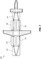
FIG. 1 is a diagrammatic illustration illustrating a networked aircraft, in accordance with example embodiments of this disclosure; -
FIG. 2 is a diagrammatic illustration illustrating air vehicle systems (AVS) and mission systems (MS) networks of the aircraft ofFIG. 1 ; -
FIG. 3 is a diagrammatic illustration illustrating components of the AVS and MS networks of the aircraft ofFIG. 1 ; -
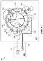
FIG. 4 is a diagrammatic illustration of components of the MS network ofFIG. 3 ; -
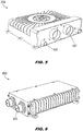
FIG. 5 is an isometric view of a smart network access point (SNAP) device of the AVS and MS networks ofFIGS. 1 through 3 ; -
FIG. 6 is an isometric view of an adaptive I/O access point (AIAP) device of the AVS and MS networks ofFIGS. 1 through 3 ; -
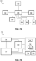
FIGS. 7A and 7B are block diagrams of components of the SNAP device ofFIG. 5 ; -
FIG. 7C is a block diagram of components of the SNAP device ofFIG. 5 and the AIAP device ofFIG. 6 ; -
FIG. 7D is a block diagram of components of the AIAP device ofFIG. 6 ; -
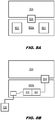
FIGS. 8A and 8B are block diagrams of components of the SNAP device ofFIG. 5 and the AIAP device ofFIG. 6 ; -
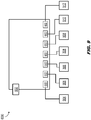
FIG. 9 is a block diagram of components and operations of the AIAP device ofFIG. 6 ; - and
FIG. 10 is a block diagram of an implementation of the AIAP device ofFIG. 6 . - Before explaining one or more embodiments of the disclosure in detail, it is to be understood that the embodiments are not limited in their application to the details of construction and the arrangement of the components or steps or methodologies set forth in the following description or illustrated in the drawings. In the following detailed description of embodiments, numerous specific details may be set forth in order to provide a more thorough understanding of the disclosure. However, it will be apparent to one of ordinary skill in the art having the benefit of the instant disclosure that the embodiments disclosed herein may be practiced without some of these specific details. In other instances, well-known features may not be described in detail to avoid unnecessarily complicating the instant disclosure.
- As used herein a letter following a reference numeral is intended to reference an embodiment of the feature or element that may be similar, but not necessarily identical, to a previously described element or feature bearing the same reference numeral (e.g., 1, 1a, 1b). Such shorthand notations are used for purposes of convenience only and should not be construed to limit the disclosure in any way unless expressly stated to the contrary.
- Further, unless expressly stated to the contrary, "or" refers to an inclusive or and not to an exclusive or. For example, a condition A or B is satisfied by any one of the following: A is true (or present) and B is false (or not present), A is false (or not present) and B is true (or present), and both A and B are true (or present).
- In addition, use of "a" or "an" may be employed to describe elements and components of embodiments disclosed herein. This is done merely for convenience and "a" and "an" are intended to include "one" or "at least one," and the singular also includes the plural unless it is obvious that it is meant otherwise.
- Finally, as used herein any reference to "one embodiment" or "some embodiments" means that a particular element, feature, structure, or characteristic described in connection with the embodiment is included in at least one embodiment disclosed herein. The appearances of the phrase "in some embodiments" in various places in the specification are not necessarily all referring to the same embodiment, and embodiments may include one or more of the features expressly described or inherently present herein, or any combination or sub-combination of two or more such features, along with any other features which may not necessarily be expressly described or inherently present in the instant disclosure.
- Embodiments of the inventive concepts disclosed herein are directed to a network architecture based on localized smart points of presence (SPoP) and incorporating autonomous, interconnected air vehicle systems (AVS) and mission systems (MS) communications networks which are distinctly separable and protected while remaining highly interactive with each other through a "digital backbone". While in the short term the AVS network, which is associated with a lower change velocity, may remain a traditional hub-and-spoke (e.g., point-to-point, star-topology) network with a high-speed, high-bandwidth network trunk, the MS network (which has a much higher change velocity) may adopting ring or mesh topologies to increase reliability, survivability, availability, and alleviate the need for long wiring runs. In some embodiments, the AVS network may additionally adopt ring/mesh topologies. The MS and AVS network trunks may incorporate copper or other cabling (e.g., to accommodate legacy I/O or power components); alternatively, the network trunks may be fiber optic based.
- Referring to
FIGS. 1 and2 , theaircraft 100 is shown. Theaircraft 100 may include, but is not limited to, fixed-wing craft, rotorcraft, or unmanned aircraft systems (UAS) piloted by one or more remote operators, or capable of partially or fully autonomous operation. - In embodiments, the
aircraft 100 may be compartmentalized and/or categorized into districts, each district corresponding to a physical subdivision of the aircraft and incorporating any and all network components physically located within the said district. Each district may include one or more district service access points (DSAP) through which any network components within the district may be connected to, and may exchange data with, an MS or AVS network. - In embodiments, the
aircraft 100 may be broken down intoessential districts 102 andnon-essential districts 104.Essential districts 102 may include AVS essential districts and MS essential districts; AVS essential districts may support equipment and/or services directed to aviation functions, while MS essential (and non-essential) districts may support mission-related equipment and/or services. For example, AVS network components or services may include, but are not limited to, flight control and/or air vehicle computers, human/machine interfaces (HMI), autonomous command and control (C2) and payload systems, communications antennas and tuners, standby instrumentation, landing gear and lighting control systems, vehicle management sensors (e.g., engine, transmission, fuel), and onboard navigational instruments (e.g., radar altimeter (radalt), VOR/ILS, air data computers (ADC), embedded GPS/inertial (EGI) positioning systems). MS network components and services may include, but are not limited to, mission computers and/or display systems (e.g., including DVE processing systems and/or 3D sensors), flight/mission data recorders, weather sensors and/or receivers, head-mounted display (HMD) systems and head trackers, weapons and targeting systems, survivability components and countermeasures, and tactical communications systems (e.g., LOS/BLOS radio systems, SATCOM radio systems, tactical data links). "Essential" equipment or services may refer to any mission-critical network component incorporating dual redundancies (e.g., to avoid a single point of failure and ensure high availability) and/or any network component operating or operable on local battery power (as described in greater detail below). Similarly, non-essential network components include any network components that are not essential, e.g., without which mission objectives may be fulfilled via alternative means. - In embodiments,
essential districts 102 may include both essential and non-essential components, whilenon-essential districts 104 support solely non-essential components. Referring in particular toFIG. 2 , theaircraft 100 may incorporate anAVS network 202 having a star topology (e.g., hub-and-spoke) comprising a number of smart network access point (SNAP)devices 204, each SNAP device connected to a central/hub SNAP device 204a via AVS network trunk 206 (e.g., fiber optic, copper/wired or cable connection) and serving as a DSAP for any AVS network components or devices within its district. Similarly, theaircraft 100 may incorporate anMS network 208 comprising a group ofSNAP devices 204 connected in a ring topology via an MS network trunk 210 (e.g., fiber optic trunk cable). For example, theAVS network 202 andMS network 208 may be independent and isolated from each other but directly connected via one or more network bridges 212 (e.g., dual redundant guard/network bridge). In embodiments, each district (essential districts 102 and non-essential districts 104) may include at least oneSNAP device 204, e.g., at least one AVS SNAP device of theAVS network 202 and at least one MS SNAP device of theMS network 208. For example, some districts may include multiple SNAP devices, e.g., if the quantity of network components and/or devices within its district so requires. - By moving hub-and-spoke connections of the
AVS network 202 to the district level, the length (and weight) of cabling or wiring may be minimized while maintaining high availability. Similarly, a next-generation or high changevelocity MS network 208 may be retrofitted to an existing hub-and-spoke AVS network 202, allowing for high flexibility of functionality by supporting the addition ofnew SNAP devices 204 between existing MS SNAP devices in an MS network having a ring topology (e.g., or a mesh topology). Further,SNAP devices 204 may provide conversion support for legacy I/O and/or power components at the district level, compartmentalizing I/O and power needs within a district and providing for easier portability of features from one SNAP device to another. The replacement of legacy I/O and power components may be incentivized by the removability of conversion support features when they are no longer needed, further improving SWaP considerations. At a high level, rapid change and deployment of new MS features may be provided while preserving certified airworthy AVS features, eliminating the need for additional recertification testing. - Referring to
FIG. 3 , theaircraft 100,AVS network 202, andMS network 208 are disclosed. - In embodiments, the
AVS network 202 andMS network 208 may be connected via high bandwidth network bridges 212 (e.g., dual redundant network trunks) protected on each end bySNAP devices 204 and including assured network guards. For example, the network bridges 212 may further provide a "digital backbone" for additional shared functionalities (e.g., adaptive cooling/thermal management for dissipation or control of heat generated by components within a district) between the AVS and MS networks. - In embodiments, each
SNAP device 204 may serve as a district service access point (DSAP) for network components in its district. For example, theSNAP devices 204 of theAVS network 202 may provide network access to, e.g.,communications equipment 302,navigational sensors 304, ARINC 429data buses 306 andcompatible legacy equipment 308, and AVS displays 310. Similarly, theSNAP devices 204 of theMS network 208 may provide network access to, e.g., MIL-STD-1553data buses 312 andcompatible legacy equipment 314;sensor suites 316; MS displays 318; andmission computers 320. In some embodiments, theMS network 208 may be configured in a mesh topology rather than the ring topology shown by, e.g.,FIG. 2 , whereby someSNAP devices 204 are directly connected (322) in addition to their ring neighbors on theMS network trunk 210. In embodiments, theSNAP devices 204 may provide district-level management for, e.g., power distribution and control; thermal management and adaptive cooling (e.g., management of heat generated by the network components within a district); network access; I/O conversion and distribution; and encryption/decryption. For example, aSNAP device 204 may incorporate additional software and/or hardware components depending on the DSAP services provided within its district, as described in greater detail below. - Referring to
FIG. 4 , theaircraft 100,AVS network 202, andMS network 208 is disclosed. - In embodiments, the MS network 208 (as well as the
AVS network 202, not shown here in equivalent detail) may comprise multiple local area networks, connected viaMS network trunks 210a-b, for itsessential districts 102 andnon-essential districts 104. For example, theessential district 102a may include both essential and non-essential network components, serviced byessential SNAP devices 204b andnon-essential SNAP device 204c. Similarly, theessential district 102b may includeessential SNAP device 204b (with network bridging (212) toAVS SNAP device 204d) andnon-essential SNAP device 204c. Thenon-essential districts 104b-c may each includenon-essential SNAP devices 204c (the latter SNAP device of thenon-essential district 104c also incorporating network bridging 212 toAVS SNAP device 204e), and thenon-essential district 104d may includenon-essential SNAP device 204c, which may serve as a subnetwork hub for thesubnetwork 402. - In embodiments, each
MS network trunk 210a-b connecting a local area network within theMS network 208 may incorporate backbone rings 404, 406, 408. For example, adata ring 404 may provide primary control and data functionality for theMS network 208. A dedicated video/sensor ring 406 may provide high-bandwidth raw video (e.g., main cameras/heads-up displays, weather radar, fire control, forward-looking infrared radar (FLIR)). Atime ring 408 may provide accurate and time-sensitive distribution of precise timing synchronization information throughout theMS network 208 and, through theSNAP devices 204b-e, to network components and devices served by the SNAP devices. - Referring now to
FIG. 5 , theSNAP device 204 is disclosed. - In embodiments, the
SNAP device 204 may includenetwork trunk ports 502 capable of accepting network trunk connections (e.g., AVS network trunk (FIG. 2 , 206), MS network trunk (FIG. 2 , 210) for incorporation into an AVS network (FIG. 2 , 202) or MS network (FIG. 2 , 208). TheSNAP device 204 may includeadditional device ports 504 for accepting physical links (e.g., coaxial, fiber, copper) to AVS or MS network components or devices within a district served by the SNAP device. - In embodiments, each
SNAP device 204 may be capable of controlling multiple standard functions, e.g., cybersecurity, trunk networking, power control and distribution, district networking, and adaptive cooling/thermal management. In some embodiments, aSNAP device 204 may be required to manage additional functionalities, e.g., power transformation, district-level data concentration, and/or district-level isolated power distribution - Referring also to
FIG. 6 , an adaptive I/O access point device 600 (AIAP, AdAPt) is disclosed. In embodiments, theSNAP device 204 may incorporate anAIAP device 600 in order to provide network access to, and data exchange with, a fiber optic MS network (FIG. 2 , 208) or AVS network (FIG. 2 , 202) and legacy network components or equipment viadevice ports 602, e.g., legacy equipment (FIG. 3 : 308, 314) compatible with MIL-STD-1553 and/or ARINC 429 data buses (FIG. 3 : 306, 312) or, e.g., discrete or serial interfaces. In some embodiments, theAIAP device 600 may incorporate additional components, e.g., for data guard and/or encryption/decryption capabilities, as described in greater detail below. - Referring to
FIG. 7A and 7B , theSNAP device 204 is disclosed. - Referring in particular to
FIG. 7A , theSNAP device 204 may include, in addition tonetwork trunk ports 502 and device ports 504 (e.g., district switch ports),network bridging ports 702 for accepting network bridging (FIG. 2 , 212), e.g., to an AVS network (FIG. 2 , 202) if theSNAP device 204 is part of an MS network (FIG. 2 , 208), or to the MS network if the SNAP device is part of the AVS network. - In embodiments, the
SNAP device 204 may include aring switch 704 andnetwork processors 706 for handling data exchanges and component management within the district served by the SNAP device. Referring also toFIG. 7B , thenetwork processors 706 may include time management modules 708 (e.g., capable of sending or receiving timing information via the time ring (FIG. 4 , 408)), device/network management modules 710,cybersecurity management modules 712,power management modules 714, andnetwork endpoints 716. Thebridge core 718 may connect thenetwork processors 706 to thenetwork trunk ports 502 anddevice ports 504. It is contemplated that theSNAP device 204 may support a 10Gb MS network 208 with a growth path to 100 Gb. - Referring also to
FIG. 7C , theSNAP device 204f may be implemented and may function similarly to theSNAP devices FIGS. 1 through 7B , except that theSNAP device 204f may incorporate anAIAP device 600 via adevice port 504. - In embodiments, the
SNAP device 204f may (e.g., via power management modules (FIG. 7B , 714)) control the distribution of operating power to network components and devices within its district. For example, theSNAP device 204f may incorporatepower converters 720 capable of receiving operating power from anaircraft power supply 722 and, via electronic circuit breakers 724 (ECB), supplying operating power to theAIAP device 600 and/or legacy network components and devices (726) served by theSNAP device 204f via the AIAP device. For example, thepower converters 720 may convert received 270V operating power to 28V for distribution to the network components and devices. In some embodiments, theSNAP device 204f may control the distribution of operating power through alocal battery 728. - In embodiments, additional functionalities provided by the AIAP device 600 (e.g., to legacy network components and devices via AIAP device ports 602) may be managed by
local processors 730. Referring also toFIG. 7D , in embodiments, the AIAPlocal processors 730 may incorporate AIAP device and I/O management modules 732,cybersecurity management modules 734, and an edge I/O core 736 for control of, e.g.,general computing 736a, data guarding 736b, data relay androuting 736c,data transformation 736d (e.g., between copper/wired and fiber-optic components), data encryption/decryption 736e, andnetwork endpoint services 736f. - Referring to
FIG. 8A , theAIAP device 600a may be implemented and may function similarly to theAIAP device 600 ofFIGS. 6 through 7D , except that theAIAP device 600a appended to the SNAP device 204 (e.g., via device port 504) may incorporate a district-level data concentrator unit 802 (DCU) and/or district-level Ethernet switch 804 (e.g., to provide network access for Ethernet network components to a fiber-optic MS network (FIG. 2 , 208). - In some embodiments, the
SNAP device 204 andAIAP device 600a may connect to existing cross-domain guard and/or Multiple Levels of Security (MLS) encryption/decryption equipment to provide added cybersecurity for district-level legacy network components and devices having security classifications different than theMS network 208. Referring toFIG. 8B , theAIAP device 600b may be implemented and may function similarly to theAIAP devices FIGS. 6 through 8A , except that theAIAP device 600b may incorporatecross-domain guard functionality 806 and MLS encryption/decryption 808 (e.g., via AIAP cybersecurity management modules (FIG. 7D , 732)) for providing cybersecurity and data guard services incorporating multiple levels of assurance to legacy network components and devices (726). - Referring to
FIG. 9 , theAIAP device 600 is disclosed. - In embodiments, the
AIAP device 600 may provide signal conditioning, MLS data guarding, and/or encryption and decryption of data exchanged between legacy components and devices (e.g., connected via AIAP device ports 602) and the MS network (FIG. 2 , 208), e.g., USB-connected components (902); Ethernet links and/or networking components (904); Avionics Full-Duplex Switched Ethernet (AFDX) and other like ARINC 664-compatible components (906); MIL-STD-1553 data buses (308); ARINC 429 data buses (306); serial connections and/or components (908; e.g., RS-232, RS-422, RS-485); analog network components (910); and discrete-port connected components (912). - For example, as described above if the AIAP device incorporates MLS encryption/decryption (
FIG. 8B , 808) and/or cross-domain guarding (FIG. 8B , 806) as described above. Further, theAIAP device 600 may provide data relay and routing, multiplexing (muxing) and demultiplexing (demuxing) and transformation of exchanged data between network components (e.g., copper-to-fiber, fiber-to-copper, fiber-to-fiber, copper-to-copper). - Referring to
FIG. 10 , anAIAP backplane implementation 1000 is disclosed. TheAIAP backplane implementation 1000 may includemultiple AIAP devices 600. - In embodiments, the
AIAP backplane implementation 1000 may provide access to the MS network (FIG. 2 , 208) via theAIAP devices 600 to fiber-optic and legacy network components and devices, e.g., via fiber-optic connections 1002 or legacy wired connections (including, but not limited to, Ethernet links and/orcables 904;serial connections 908; ARINC 429data buses 306; and MIL-STD-1553 data buses 308). Connected network component and devices may include, but are not limited to,mission computers 320; sensor suites (FIG. 3 , 316; e.g.,flight sensor suites 1004,mission sensors 1006, cameras/image sensors 1008);input devices 1010; AFDX and other Ethernet switches 906;flight computers 1012; display systems (e.g., flight crew displays 1014, mission displays 1016). - It is to be understood that embodiments of the methods disclosed herein may include one or more of the steps described herein. Further, such steps may be carried out in any desired order and two or more of the steps may be carried out simultaneously with one another. Two or more of the steps disclosed herein may be combined in a single step, and in some embodiments, one or more of the steps may be carried out as two or more sub-steps. Further, other steps or sub-steps may be carried in addition to, or as substitutes to one or more of the steps disclosed herein.
- Although inventive concepts have been described with reference to the embodiments illustrated in the attached drawing figures, equivalents may be employed and substitutions made herein without departing from the scope of the claims. Components illustrated and described herein are merely examples of a system/device and components that may be used to implement embodiments of the inventive concepts and may be replaced with other devices and components without departing from the scope of the claims. Furthermore, any dimensions, degrees, and/or numerical ranges provided herein are to be understood as non-limiting examples unless otherwise specified in the claims.
Claims (8)
- A smart network access point (SNAP) device (204), comprising:two or more trunk ports (502) configured to accept a network trunk cable, the SNAP device connectible to an aircraft network via the network trunk cable;a plurality of switch ports, each switch port configured to accept a physical link to one or more district components disposed within a district associated with a physical subdivision of an aircraft;one or more control processors (706) including:a network management module (710) configured for monitoring one or more exchanges of data between the one or more district components and the aircraft network;a cybersecurity module (712) configured for encryption and decryption of the exchanged data;
anda power management module (714) configured for controlling the distribution of operating power to the one or more district components. - The SNAP device of claim 1, wherein the power management module includes one or more power control components selected from:a power converter operatively coupled to a power supply of the aircraft;an electronic circuit breaker (ECB) configured to supply converted power to the one or more district components;
anda local battery configured to supply operating power to the one or more district components. - The SNAP device of claim 1 or 2, further comprising:
at least one time management module configured for time synchronization of the control processors and the one or more district components to the aircraft network. - The SNAP device of any preceding claim, wherein the aircraft network is a first aircraft network, further comprising:
at least one bridging port configured to accept a network bridging cable, the SNAP device configured for connecting the first aircraft network to a second aircraft network via the network bridging cable. - The SNAP device of any preceding claim, wherein the one or more district components include one or more legacy components coupled to the SNAP device via a wired interface, further comprising:
at least one adaptive input/output (I/O) module configured for monitoring the one or more exchanges of data between the one or more legacy components and the aircraft network. - The SNAP device of claim 5 above, wherein the wired interface is selected from:a serial data bus according to MIL-STD-1553;an avionics data bus according to ARINC 429;
andan Ethernet networking component. - The SNAP device of claim 5 above, wherein the at least one adaptive I/O module includes:at least one multiple levels of security (MLS) encryption/decryption module configured to encrypt and decrypt the one or more data exchanges;
andat least one cross-domain guard. - The SNAP device of any preceding claim, wherein the network management module includes at least one data concentrator unit (DCU).
Applications Claiming Priority (3)
| Application Number | Priority Date | Filing Date | Title |
|---|---|---|---|
| US201962915556P | 2019-10-15 | 2019-10-15 | |
| US17/067,463 US11563642B2 (en) | 2019-10-15 | 2020-10-09 | Smart point of presence (SPOP) aircraft-based high availability edge network architecture |
| US17/067,500 US11477088B2 (en) | 2019-10-15 | 2020-10-09 | Smart point of presence (SPOP) devices for aircraft-based high availability edge network architecture |
Publications (1)
| Publication Number | Publication Date |
|---|---|
| EP3809670A1 true EP3809670A1 (en) | 2021-04-21 |
Family
ID=73020043
Family Applications (2)
| Application Number | Title | Priority Date | Filing Date |
|---|---|---|---|
| EP20202103.6A Active EP3809669B1 (en) | 2019-10-15 | 2020-10-15 | Smart point of presence (spop) aircraft-based high availability edge network architecture |
| EP20202108.5A Pending EP3809670A1 (en) | 2019-10-15 | 2020-10-15 | Smart point of presence (spop) devices for aircraft-based high availability edge network architecture |
Family Applications Before (1)
| Application Number | Title | Priority Date | Filing Date |
|---|---|---|---|
| EP20202103.6A Active EP3809669B1 (en) | 2019-10-15 | 2020-10-15 | Smart point of presence (spop) aircraft-based high availability edge network architecture |
Country Status (2)
| Country | Link |
|---|---|
| US (1) | US11477088B2 (en) |
| EP (2) | EP3809669B1 (en) |
Cited By (2)
| Publication number | Priority date | Publication date | Assignee | Title |
|---|---|---|---|---|
| US11477088B2 (en) * | 2019-10-15 | 2022-10-18 | Rockwell Collins, Inc. | Smart point of presence (SPOP) devices for aircraft-based high availability edge network architecture |
| US11563642B2 (en) | 2019-10-15 | 2023-01-24 | Rockwell Collins, Inc. | Smart point of presence (SPOP) aircraft-based high availability edge network architecture |
Citations (3)
| Publication number | Priority date | Publication date | Assignee | Title |
|---|---|---|---|---|
| US20040235469A1 (en) * | 2003-05-21 | 2004-11-25 | Krug William P. | High bandwidth open wired network |
| US20070217622A1 (en) * | 2006-03-15 | 2007-09-20 | Tomotaka Takeuchi | Wireless client device |
| US20190306030A1 (en) * | 2018-03-29 | 2019-10-03 | Kuang Yi Chen | Modular Meshed Radio Nodes Networking Topology for Kinematic Objects |
Family Cites Families (26)
| Publication number | Priority date | Publication date | Assignee | Title |
|---|---|---|---|---|
| US8995993B2 (en) * | 2000-10-11 | 2015-03-31 | Gogo Llc | System for managing mobile internet protocol addresses in an airborne wireless cellular network |
| US7181017B1 (en) * | 2001-03-23 | 2007-02-20 | David Felsher | System and method for secure three-party communications |
| US7660901B1 (en) * | 2003-02-04 | 2010-02-09 | Cisco Technology, Inc. | Method and apparatus for defining a user specific configuration environment |
| IL155050A0 (en) * | 2003-03-24 | 2003-10-31 | Supercom Ltd | System and method for monitoring, controlling and reporting access and attendance and behavior |
| US7660271B2 (en) * | 2005-08-11 | 2010-02-09 | Cisco Technology, Inc. | Spanning tree BPDU processing method and system facilitating integration of different native VLAN configurations |
| US8130773B2 (en) | 2008-06-25 | 2012-03-06 | Honeywell International Inc. | Hybrid topology ethernet architecture |
| US8369295B2 (en) * | 2008-09-04 | 2013-02-05 | Mark Stephen Thompson | Method to provide connectivity and power for different aircraft sub-systems varying in levels of criticality and intended purposes while using a single partitioned airborne local area network (ALAN) |
| DE102010030585B4 (en) | 2010-06-28 | 2012-08-09 | Airbus Operations Gmbh | Static mesh network, aircraft and method of data communication |
| US9894108B2 (en) * | 2010-12-13 | 2018-02-13 | At&T Intellectual Property I, L.P. | Synchronization based on device presence |
| US9197600B2 (en) * | 2011-09-29 | 2015-11-24 | Israel L'Heureux | Smart router |
| US20130208630A1 (en) | 2012-02-15 | 2013-08-15 | Ge Aviation Systems Llc | Avionics full-duplex switched ethernet network |
| US9197906B1 (en) | 2012-09-13 | 2015-11-24 | Rockwell Collins, Inc. | Aircraft cabin management system |
| FR3007917B1 (en) * | 2013-06-27 | 2015-07-31 | Airbus Operations Sas | WIRELESS TELECOMMUNICATION NETWORK PARTITIONED WITH WIRELESS ACCESS |
| GB2532773A (en) | 2014-11-27 | 2016-06-01 | Airbus Operations Sas | Improvements in or relating to avionics networks |
| US9838436B2 (en) | 2015-03-30 | 2017-12-05 | Gulfstream Aerospace Corporation | Aircraft data networks |
| US9986036B2 (en) | 2015-07-16 | 2018-05-29 | Ge Aviation Systems, Llc | Apparatus and method of operating a system |
| FR3041197B1 (en) * | 2015-09-11 | 2018-08-31 | Thales | AVIONIC COMPUTER WITH INTEGRATED ROUTING MODULE, COMMUNICATION NETWORK AND ASSOCIATED COMMUNICATION PLANT, AND AIRCRAFT COMPRISING SUCH A COMMUNICATION PLANT |
| US10231140B2 (en) * | 2015-09-24 | 2019-03-12 | Cisco Technology, Inc. | Self optimizing residential and community WiFi networks |
| CN110325929B (en) * | 2016-12-07 | 2021-05-25 | 阿瑞路资讯安全科技股份有限公司 | System and method for signal waveform analysis for detecting changes in wired network |
| JP6882529B2 (en) * | 2017-02-14 | 2021-06-02 | システムズ アンド ソフトウェア エンタープライゼス, エルエルシーSystems And Software Enterprises, Llc | Dynamic and distributed mesh networks for in-flight entertainment systems |
| EP3729766A1 (en) * | 2017-12-24 | 2020-10-28 | Arilou Information Security Technologies Ltd. | System and method for tunnel-based malware detection |
| US10785699B2 (en) * | 2018-03-28 | 2020-09-22 | Apple Inc. | Next generation node-B (GNB) for integrated access and backhaul (IAB) relay in new radio (NR) networks |
| US20200029209A1 (en) * | 2018-07-23 | 2020-01-23 | Henrik Ferdinand Nölscher | Systems and methods for managing wireless communications by a vehicle |
| CN109412915B (en) | 2018-09-21 | 2021-01-05 | 湖北航天技术研究院总体设计所 | Primary and secondary aircraft communication method and system based on 1553B bus |
| US11563642B2 (en) * | 2019-10-15 | 2023-01-24 | Rockwell Collins, Inc. | Smart point of presence (SPOP) aircraft-based high availability edge network architecture |
| US11477088B2 (en) * | 2019-10-15 | 2022-10-18 | Rockwell Collins, Inc. | Smart point of presence (SPOP) devices for aircraft-based high availability edge network architecture |
-
2020
- 2020-10-09 US US17/067,500 patent/US11477088B2/en active Active
- 2020-10-15 EP EP20202103.6A patent/EP3809669B1/en active Active
- 2020-10-15 EP EP20202108.5A patent/EP3809670A1/en active Pending
Patent Citations (3)
| Publication number | Priority date | Publication date | Assignee | Title |
|---|---|---|---|---|
| US20040235469A1 (en) * | 2003-05-21 | 2004-11-25 | Krug William P. | High bandwidth open wired network |
| US20070217622A1 (en) * | 2006-03-15 | 2007-09-20 | Tomotaka Takeuchi | Wireless client device |
| US20190306030A1 (en) * | 2018-03-29 | 2019-10-03 | Kuang Yi Chen | Modular Meshed Radio Nodes Networking Topology for Kinematic Objects |
Non-Patent Citations (2)
| Title |
|---|
| ALENA R L ET AL: "Communications for Integrated Avionics", INTERNET CITATION, 27 December 2006 (2006-12-27), XP002451879, Retrieved from the Internet <URL:http://ic.arc.nasa.gov/publications/pdf/1277.pdf> [retrieved on 20070101] * |
| IAN MOIR ET AL: "Military Avionics Systems", 1 January 2006 (2006-01-01), pages 47 - 97, XP055278208, ISBN: 978-0-470-01632-9, Retrieved from the Internet <URL:https://www.wiley.com/en-us/Military+Avionics+Systems-p-9780470016329> [retrieved on 20160606] * |
Cited By (2)
| Publication number | Priority date | Publication date | Assignee | Title |
|---|---|---|---|---|
| US11477088B2 (en) * | 2019-10-15 | 2022-10-18 | Rockwell Collins, Inc. | Smart point of presence (SPOP) devices for aircraft-based high availability edge network architecture |
| US11563642B2 (en) | 2019-10-15 | 2023-01-24 | Rockwell Collins, Inc. | Smart point of presence (SPOP) aircraft-based high availability edge network architecture |
Also Published As
| Publication number | Publication date |
|---|---|
| US11477088B2 (en) | 2022-10-18 |
| EP3809669A1 (en) | 2021-04-21 |
| EP3809669B1 (en) | 2025-06-25 |
| US20210351988A1 (en) | 2021-11-11 |
Similar Documents
| Publication | Publication Date | Title |
|---|---|---|
| US11563642B2 (en) | Smart point of presence (SPOP) aircraft-based high availability edge network architecture | |
| US8032032B2 (en) | Bi-directional optical link between multiple data sources and a processing node in an avionics platform | |
| EP2345181B1 (en) | Methods and systems for providing full avionics data services over a single fiber | |
| US10230574B2 (en) | Avionics calculator with integrated routing module, related communication network and communication installation, and aircraft comprising such a communication installation | |
| US6801769B1 (en) | Modular aircraft information network system and an associated method of packaging the same | |
| US11477088B2 (en) | Smart point of presence (SPOP) devices for aircraft-based high availability edge network architecture | |
| US8078055B1 (en) | Passive optical avionics network | |
| KR101113513B1 (en) | Ship with a data network | |
| US9660757B2 (en) | Low latency fiber optic local area network | |
| EP3353919B1 (en) | Fault tolerant optical apparatus | |
| US20170001583A1 (en) | System for electrically connecting cabin equipment of an aircraft to a control system and to at least one electrical power supply source of the aircraft | |
| US20070230429A1 (en) | On-board cdma communication networkforecast | |
| US9503192B2 (en) | Data network, aircraft or spacecraft, and method | |
| Collinson | Avionics systems integration | |
| US11329752B2 (en) | Reconfigurable optical backplane | |
| US10027570B2 (en) | Communication network on board a vehicle and a switch of such a communication network | |
| US11139992B1 (en) | Systems and methods for remotely powered data concentrators for distributed IMA system | |
| US10270887B2 (en) | Server system, aircraft or spacecraft and method | |
| US20200274632A1 (en) | Method for managing data in a transportation cabin and standardised implementation architecture | |
| Kosyanchuk et al. | Analysis of the requirements to information exchange protocol for an all-optical onboard network | |
| US20200412575A1 (en) | Vehicle having fail-safe internal data transfer | |
| Chen et al. | Multi-Gb/s fiberoptic physical layer for spacecraft interconnects | |
| Zhang et al. | Developing a generic optical avionic network | |
| Braun | Hybrid WDM ring-bus optical network |
Legal Events
| Date | Code | Title | Description |
|---|---|---|---|
| PUAI | Public reference made under article 153(3) epc to a published international application that has entered the european phase |
Free format text: ORIGINAL CODE: 0009012 |
|
| STAA | Information on the status of an ep patent application or granted ep patent |
Free format text: STATUS: THE APPLICATION HAS BEEN PUBLISHED |
|
| AK | Designated contracting states |
Kind code of ref document: A1 Designated state(s): AL AT BE BG CH CY CZ DE DK EE ES FI FR GB GR HR HU IE IS IT LI LT LU LV MC MK MT NL NO PL PT RO RS SE SI SK SM TR |
|
| AX | Request for extension of the european patent |
Extension state: BA ME |
|
| STAA | Information on the status of an ep patent application or granted ep patent |
Free format text: STATUS: REQUEST FOR EXAMINATION WAS MADE |
|
| 17P | Request for examination filed |
Effective date: 20211020 |
|
| RBV | Designated contracting states (corrected) |
Designated state(s): AL AT BE BG CH CY CZ DE DK EE ES FI FR GB GR HR HU IE IS IT LI LT LU LV MC MK MT NL NO PL PT RO RS SE SI SK SM TR |
|
| STAA | Information on the status of an ep patent application or granted ep patent |
Free format text: STATUS: EXAMINATION IS IN PROGRESS |
|
| 17Q | First examination report despatched |
Effective date: 20250116 |