EP3809645A1 - Control device and control method - Google Patents
Control device and control method Download PDFInfo
- Publication number
- EP3809645A1 EP3809645A1 EP19840185.3A EP19840185A EP3809645A1 EP 3809645 A1 EP3809645 A1 EP 3809645A1 EP 19840185 A EP19840185 A EP 19840185A EP 3809645 A1 EP3809645 A1 EP 3809645A1
- Authority
- EP
- European Patent Office
- Prior art keywords
- master station
- control
- slave station
- station apparatus
- switching
- Prior art date
- Legal status (The legal status is an assumption and is not a legal conclusion. Google has not performed a legal analysis and makes no representation as to the accuracy of the status listed.)
- Granted
Links
Images




Classifications
-
- H—ELECTRICITY
- H04—ELECTRIC COMMUNICATION TECHNIQUE
- H04W—WIRELESS COMMUNICATION NETWORKS
- H04W28/00—Network traffic management; Network resource management
- H04W28/02—Traffic management, e.g. flow control or congestion control
- H04W28/08—Load balancing or load distribution
- H04W28/086—Load balancing or load distribution among access entities
- H04W28/0861—Load balancing or load distribution among access entities between base stations
- H04W28/0864—Load balancing or load distribution among access entities between base stations of different hierarchy levels, e.g. Master Evolved Node B [MeNB] or Secondary Evolved node B [SeNB]
-
- H—ELECTRICITY
- H04—ELECTRIC COMMUNICATION TECHNIQUE
- H04L—TRANSMISSION OF DIGITAL INFORMATION, e.g. TELEGRAPHIC COMMUNICATION
- H04L45/00—Routing or path finding of packets in data switching networks
- H04L45/38—Flow based routing
-
- H—ELECTRICITY
- H04—ELECTRIC COMMUNICATION TECHNIQUE
- H04L—TRANSMISSION OF DIGITAL INFORMATION, e.g. TELEGRAPHIC COMMUNICATION
- H04L45/00—Routing or path finding of packets in data switching networks
- H04L45/46—Cluster building
-
- H—ELECTRICITY
- H04—ELECTRIC COMMUNICATION TECHNIQUE
- H04L—TRANSMISSION OF DIGITAL INFORMATION, e.g. TELEGRAPHIC COMMUNICATION
- H04L47/00—Traffic control in data switching networks
- H04L47/10—Flow control; Congestion control
- H04L47/12—Avoiding congestion; Recovering from congestion
- H04L47/125—Avoiding congestion; Recovering from congestion by balancing the load, e.g. traffic engineering
-
- H—ELECTRICITY
- H04—ELECTRIC COMMUNICATION TECHNIQUE
- H04L—TRANSMISSION OF DIGITAL INFORMATION, e.g. TELEGRAPHIC COMMUNICATION
- H04L49/00—Packet switching elements
- H04L49/15—Interconnection of switching modules
-
- H—ELECTRICITY
- H04—ELECTRIC COMMUNICATION TECHNIQUE
- H04W—WIRELESS COMMUNICATION NETWORKS
- H04W40/00—Communication routing or communication path finding
- H04W40/34—Modification of an existing route
-
- H—ELECTRICITY
- H04—ELECTRIC COMMUNICATION TECHNIQUE
- H04W—WIRELESS COMMUNICATION NETWORKS
- H04W84/00—Network topologies
- H04W84/18—Self-organising networks, e.g. ad-hoc networks or sensor networks
- H04W84/20—Leader-follower arrangements
-
- H—ELECTRICITY
- H04—ELECTRIC COMMUNICATION TECHNIQUE
- H04L—TRANSMISSION OF DIGITAL INFORMATION, e.g. TELEGRAPHIC COMMUNICATION
- H04L45/00—Routing or path finding of packets in data switching networks
- H04L45/42—Centralised routing
-
- H—ELECTRICITY
- H04—ELECTRIC COMMUNICATION TECHNIQUE
- H04L—TRANSMISSION OF DIGITAL INFORMATION, e.g. TELEGRAPHIC COMMUNICATION
- H04L45/00—Routing or path finding of packets in data switching networks
- H04L45/44—Distributed routing
-
- H—ELECTRICITY
- H04—ELECTRIC COMMUNICATION TECHNIQUE
- H04W—WIRELESS COMMUNICATION NETWORKS
- H04W88/00—Devices specially adapted for wireless communication networks, e.g. terminals, base stations or access point devices
- H04W88/08—Access point devices
- H04W88/085—Access point devices with remote components
Definitions
- the present disclosure relates to a control apparatus and a control method.
- C-RAN Centralized-Radio Access Network
- Fig. 11 is a diagram illustrating a configuration of a communication system 1 of C-RAN in the related art.
- master station devices 101 101 (101-1 to 101-3) and slave station devices 201 (201-1 to 201-3) are connected to each other on a one-to-one basis, and the plurality of master station devices 101-1 to 101-3 are aggregated at one location.
- the master station device 101-1 is connected to the slave station device 201-1
- the master station device 101-2 is connected to the slave station device 201-2
- the master station device 101-3 is connected to the slave station device 201-3.
- Non Patent Literature 2 a technique for reducing the amount of transmission data by redefining the division of functions of a master station device and a slave station device has been examined.
- Division points in the redefinition of the division of functions include a plurality of candidates.
- a master station device and a slave station device are constituted by a Packet Data Convergence Protocol (PDCP) layer, a Radio Link Control (RLC) layer, a Media Access Control (MAC) layer, and a PHY layer.
- PDCP Packet Data Convergence Protocol
- RLC Radio Link Control
- MAC Media Access Control
- a division point having a function of a PDCP layer in a master station device and having functions of an RLC layer and layers below the RLC layer in a slave station device is referred to as a Higher Layer Split (HLS).
- HLS Higher Layer Split
- the amount of transmission data between a master station device and a slave station device is smaller than that of C-RAN in the related art, and a delay request also becomes less severe.
- LLS lower layer split
- a transfer device such as a switch, for example, is installed between the master station device and the slave station device.
- a transfer device transfer apparatus
- a transfer device 302 is installed between master station devices 102 (102-1 to 102-3) and slave station devices 202 (202-1 to 202-3).
- the transfer device 302 is a device that transfers data transmitted and received between the master station devices 102 (102-1 to 102-3) and the slave station devices 202 (202-1 to 202-3).
- the transfer device 302 is, for example, a switch.
- Fig. 13 is a diagram illustrating a configuration of a communication system 3 in which a plurality of transfer devices are installed.
- a plurality of transfer devices 303 (303-1 to 303-4) are installed between master station devices 103 (103-1 to 103-6) and slave station devices 203 (203-1 to 203-6).
- the transfer devices 303 are devices that transfer data transmitted and received between the master station devices 103 (103-1 to 103-6) and the slave station devices 203 (203-1 to 203-3).
- the transfer device 303 is, for example, a switch.
- the master station devices and the slave station devices are logically connected to each other on a one-to-one basis.
- processing resources of the master station devices will be used exclusively even when the amount of traffic to be processed by the slave station devices is small, and thus a large amount of processing resources of the master station devices is wasted.
- the amount of traffic of the slave station devices which are to be processed by the master station devices is excessively large, processing resources of the master station devices are insufficient. In this manner, in a case where a network is constructed between the master station devices and the slave station devices, there is a problem in that processing resources of the master station devices cannot be effectively utilized.
- an object of the present disclosure is to provide a technique making it possible to effectively utilize processing resources of a master station apparatus in a case where a network having a transfer apparatus disposed between the master station apparatus and a slave station apparatus is constructed.
- An aspect of the present disclosure is a control apparatus that controls any one or all of a plurality of slave station apparatuses, a plurality of master station apparatuses, and a transferapparatus, a slave station apparatus of the plurality of slave station apparatuses being assigned to a master station apparatus of the plurality of master station apparatuses, the master station apparatus controlling the slave station apparatus, and the transfer apparatus transferring data transmitted and received between the master station apparatus and the slave station apparatus, the control apparatus including an information acquisition unit that acquires information regarding traffic of the data transmitted and received between the master station apparatus and the slave station apparatus, and a switching control unit that performs, on the basis of the information regarding the traffic acquired by the information acquisition unit, switching-control of an assignment relationship between the master station apparatus and the slave station apparatus and switching-control of a transfer path of data between the master station apparatus and the slave station apparatus.
- the switching control unit performs switching-control of an assignment relationship to assign the other slave station apparatus assigned to the other master station apparatus to the one master station apparatus, and performs switching-control of a transfer path of data by instructing the other slave station apparatus to set destinations of data transmitted from the other slave station apparatuses assigned to the other master station apparatus to be a destination of the one master station apparatus.
- the switching control unit performs switching-control of an assignment relationship to assign the other slave station apparatus assigned to the other master station apparatus to the one master station apparatus, and performs switching-control of a transfer path of data by instructing the transfer apparatus to set destinations of data transmitted from the other slave station apparatuses assigned to the other master station apparatus to be a destination of the one master station apparatus.
- the control apparatus further includes an information sharing unit that shares, with another control apparatus, information regarding any one or all of the master station apparatus, the slave station apparatus, and the transfer apparatus that are not connected to the control apparatus, in which the switching control unit performs the switching-control of the assignment relationship and the switching-control of the transfer path of data on any one apparatus of the master station apparatus, the slave station apparatus, and the transfer apparatus that are connected to the control apparatus, using the information shared with the other control apparatus by the information sharing unit.
- the switching control unit performs switching-control of an assignment relationship to assign a slave station apparatus which is a target for switching, among the plurality of slave station apparatuses assigned to the one master station apparatus, to another master station apparatus of the plurality of master station apparatuses, and performs switching-control of a transfer path of data by instructing the slave station apparatus which is a target for switching, among the plurality of slave station apparatuses assigned to the one master station apparatus, to set a destination of data transmitted from the slave station apparatus which is a target for switching to be a destination of the other master station apparatus.
- the switching control unit performs switching-control of an assignment relationship to assign a slave station apparatus which is a target for switching, among the plurality of slave station apparatuses assigned to the one master station apparatus, to another master station apparatus of the plurality of master station apparatuses, and performs switching-control of a transfer path of data by instructing the transfer apparatus to set a destination of data transmitted from the slave station apparatus which is a target for switching, among the plurality of slave station apparatuses assigned to the one master station apparatus, to be a destination of the other master station apparatus.
- Another aspect of the present disclosure is a control method performed by a control apparatus that controls any one or all of a plurality of slave station apparatuses, a plurality of master station apparatuses, and a transfer apparatus, a slave station apparatus of the plurality of slave station apparatuses being assigned to a master station apparatus of the plurality of master station apparatuses, the master station apparatus controlling the slave station apparatus, the transfer apparatus transferring data transmitted and received between the master station apparatus and the slave station apparatus, the control method including acquiring information regarding traffic of the data transmitted and received between the master station apparatus and the slave station apparatus, and performing, on the basis of the information regarding the traffic acquired in the acquiring of the information, switching-control of an assignment relationship between the master station apparatus and the slave station apparatus and switching-control of a transfer path of data between the master station apparatus and the slave station apparatus.
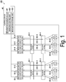
- Fig. 1 is a diagram illustrating a configuration of a communication system 100 according to a first embodiment.
- the communication system 100 includes a plurality of master station devices (master station apparatuses) 10 (10-1 to 10-6), a plurality of slave station devices (slave station apparatuses) 20 (20-1 to 20-6), a plurality of transfer devices (transfer apparatuses) 30 (30-1 to 30-4), and a control device (control apparatus) 40.
- master station apparatuses master station apparatuses
- slave station apparatuses slave station apparatuses
- transfer apparatuses transfer apparatuses
- control apparatus control apparatus
- the master station devices 10-1 to 10-3 are connected to the transfer device 30-1.
- the master station devices 10-4 to 10-6 are connected to the transfer device 30-2.
- the slave station devices 20-1 to 20-3 are connected to the transfer device 30-3.
- the slave station devices 20-4 to 20-6 are connected to the transfer device 30-4.
- the control device 40 is connected to the master station devices 10-1 to 10-6 and the plurality of slave station devices 20-1 to 20-6.
- the transfer device 30-1 is connected to the transfer device 30-2 and the transfer device 30-3 in addition to the master station devices 10-1 to 10-3.
- the transfer device 30-2 is connected to the transfer device 30-1 and the transfer device 30-4 in addition to the master station devices 10-4 to 10-6.
- the transfer device 30-3 is connected to the transfer device 30-1 and the transfer device 30-4 in addition to the slave station devices 20-1 to 20-3.
- the transfer device 30-4 is connected to the transfer device 30-2 and the transfer device 30-3 in addition to the slave station devices 20-4 to 20-6.
- arrows 50-1 to 50-6 illustrated in Fig. 1 indicate transfer paths of data.
- the arrow 50-1 represents a transfer path of data from the master station device 10-1 to the slave station device 20-1 in a downlink, and a transfer path of data from the slave station device 20-1 to the master station device 10-1 in an uplink.
- the master station device 10 controls the slave station device 20 assigned to the master station device 10.
- the master station devices 10 and the slave station devices 20 are logically connected to each other on a one-to-one basis.
- the slave station device 20-1 is assigned to the master station device 10-1
- the slave station device 20-2 is assigned to the master station device 10-2
- the slave station device 20-3 is assigned to the master station device 10-3
- the slave station device 20-4 is assigned to the master station device 10-4
- the slave station device 20-5 is assigned to the master station device 10-5
- the slave station device 20-6 is assigned to the master station device 10-6.
- the master station device 10 stores information regarding the slave station device 20 assigned to the master station device 10.
- the information regarding the slave station device 20 is information for identifying the slave station device 20 and is, for example, a MAC address of the slave station device 20, or the like.
- the master station device 10 transmits and receives data to and from the slave station device 20 assigned to the master station device 10 in a case where control is not performed by the control device 40. In a case where control is performed by the control device 40, the master station device 10 changes an assignment relationship and transmits and receives data to and from the slave station device 20 instructed by the control device 40.
- the slave station device 20 communicates with a terminal device not illustrated in the drawing.
- the slave station device 20 transmits and receives data to and from the master station device 10 to which the slave station device 20 is assigned in a case where control is not performed by the control device 40.
- the slave station device 20 changes an assignment relationship and transmits and receives data to and from the master station device 10 instructed by the control device 40.
- the transfer device 30 transfers data transmitted and received between the master station device 10 and the slave station device 20 to a destination included in the data.
- the transfer device 30 is, for example, a switch.
- the control device 40 controls the master station device 10 and the slave station device 20. Specifically, the control device 40 performs switching-control of an assignment relationship between the master station device 10 and the slave station device 20, and switching-control of a transfer path of data between the master station device 10 and the slave station device 20.
- control device 40 Next, a functional configuration of the control device 40 will be described.
- the control device 40 includes a central processing unit (CPU), a memory, an auxiliary storage device, and the like connected to each other through a bus and executes a control program.
- the control device 40 functions as a device including an information acquisition unit 401, a switching control unit 402, and an information storage unit 403 by executing the control program.
- all or some functions of the control device 40 may be realized using hardware such as an application specific integrated circuit (ASIC), a programmable logic device (PLD), or a field programmable gate array (FPGA).
- the control program may be recorded in a computer-readable recording medium.
- the computer-readable recording medium is, for example, a portable medium such as a flexible disk, a magneto-optical disk, a ROM or a CD-ROM, or a storage device such as a hard disk drive built into a computer system.
- the control program may be transmitted and received through an electrical communication line.
- the information acquisition unit 401 acquires information regarding traffic by monitoring traffic of data transmitted and received between the master station device 10 and the slave station device 20.
- the information regarding traffic is, for example, information of the amount of traffic.
- the information acquisition unit 401 acquires the amount of traffic from the master station devices 10-1 to 10-6 to the slave station devices 20-1 to 20-6 in a downlink and the amount of traffic from the slave station devices 20-1 to 20-6 to the master station devices 10-1 to 10-6 in an uplink.
- the switching control unit 402 performs switching-control of an assignment relationship between the master station device 10 and the slave station device 20 and switching-control of a transfer path of data between the master station device 10 and the slave station device 20 in response to traffic detected by the information acquisition unit 401.
- the information storage unit 403 stores information regarding a device to which the control device 40 is connected (hereinafter referred to as "connection device information"). For example, the information storage unit 403 stores processing resources of the master station device 10 and information of the slave station device 20 assigned to the master station device 10, for each master station device 10. In addition, for example, the information storage unit 403 stores information of the master station device 10 to which the slave station device 20 is assigned for each slave station device 20.
- the information storage unit 403 is constituted using a storage device such as a magnetic hard disk device or a semiconductor storage device.
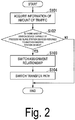
- Fig. 2 is a flowchart illustrating a flow of processing of the control device 40 according to the first embodiment.
- the information acquisition unit 401 acquires the amount of traffic of each of the master station devices 10 by monitoring traffic of data transmitted and received between the master station device 10 and the slave station device 20 (step S101). For example, the information acquisition unit 401 may monitor traffic output from the master station device 10 to acquire the amount of traffic of each of the master station devices 10, or may monitor traffic input from the master station device 10 to acquire the amount of traffic of each of the master station devices 10. The information acquisition unit 401 outputs information of the acquired amount of traffic to the switching control unit 402.
- the switching control unit 402 determines whether there is a master station device 10 capable of processing the slave station device 20 assigned to another master station device 10 on the basis of the information of the amount of traffic which is output from the information acquisition unit 401 and the connection device information stored in the information storage unit 403 (step S102). Specifically, the switching control unit 402 adds the amount of traffic of the slave station device 20 assigned to a certain master station device 10 and the amount of traffic of at least one slave station device 20 among the plurality of slave station devices 20 assigned to other master station devices 10, and determines that there is a master station device 10 capable of processing the slave station device 20 assigned to another master station device 10 in a case where the sum does not exceed processing resources of the master station device 10.
- the switching control unit 402 adds the amount of traffic of the slave station device 20-1 assigned to the master station device 10-1 and the amount of traffic of the slave station device 20-2 assigned to the other master station device 10-2, and determines that there is a master station device 10 capable of processing the slave station device 20-2 assigned to the other master station device 10-2 in a case where the sum does not exceed processing resources of the master station device 10-1.
- control device 40 terminates the processing of Fig. 2 .
- the switching control unit 402 performs switching-control of an assignment relationship (step S103). Specifically, the switching control unit 402 instructs the master station device 10 and the slave station device 20 which are targets for switching of an assignment relationship to switch the assignment relationship.
- the switching control unit 402 gives an instruction for switching an assignment relationship so that all of the slave station devices 20-1 to 20-3 are assigned to the master station device 10-1.
- the switching control unit 402 instructs the master station devices 10-1 to 10-3 to switch an assignment relationship so that all of the slave station devices 20-1 to 20-3 are assigned to the master station device 10-1.
- the master station devices 10-1 to 10-3 and the slave station devices 20-1 to 20-3 change their own setting.
- the master station device 10-2 cancels an assignment relationship with the slave station device 20-2
- the master station device 10-3 cancels an assignment relationship with the slave station device 20-3.
- the slave station devices 20-1 to 20-3 change the setting of the slave station devices 20-1 to 20-3 to be assigned to the master station device 10-1.
- the master station device 10-1 changes the setting of the master station device 10-1 to assign the slave station devices 20-1 to 20-3 to the master station device 10-1.
- the switching control unit 402 performs switching-control of a transfer path (step S104).
- the switching control unit 402 performs switching-control of a transfer path so that data is transmitted and received to and from the device after an assignment relationship is changed. For example, in the above-described example, the switching control unit 402 switches a transfer path so that data is transmitted and received between the master station device 10-1 and the slave station devices 20-1 to 20-3.
- the switching control unit 402 performs switching-control of a transfer path by transmitting, to the master station device 10 and the slave station device 20, an instruction for changing a destination address of a frame to be transmitted in the master station device 10 and the slave station device 20.
- the switching control unit 402 transmits an instruction for setting a destination address of data to be the master station device 10-1 for the slave station devices 20-1 to 20-3 and transmits an instruction for setting a destination address of data to be the slave station devices 20-1 to 20-3 for the master station device 10-1.
- the slave station devices 20-1 to 20-3 set a destination address of data to be the master station device 10-1.
- the master station device 10-1 sets a destination address of data to be any one of the slave station devices 20-1 to 20-3.
- Fig. 3 is a diagram illustrating a configuration of the communication system 100 after switching control according to the first embodiment.
- a transfer path is switched such that data is transmitted and received between the master station device 10-1 and the slave station devices 20-1 to 20-3, and control is performed such that data is not transmitted and received to and from the master station devices 10-2 and 10-3.
- the master station devices 10-2 and 10-3 do not need to operate, and processing resources are freed up.
- the control device 40 configured as described above performs switching-control of an assignment relationship between the master station device 10 and the slave station device 20 in accordance with traffic of data transmitted and received between the master station device 10 and the slave station device 20.
- the switching-control when traffic of the slave station devices 20 assigned to other master station devices 10 can be processed by one master station device 10, the slave station devices are assigned to the master station device 10 capable of processing traffic of the slave station devices 20 assigned to other master station devices 10.
- the control device 40 performs switching-control of a transfer path of data between the master station device 10 and the slave station device 20 after switching-control of an assignment relationship is performed.
- processing resources of the master station device 10, of which assignment to the slave station device 20 has been cancelled, are freed up, and the master station device 10 to which the slave station device 20 assigned to another master station device 10 is newly assigned can utilize the processing resources. For this reason, in a case where a network is constructed between the master station device 10 and the slave station device 20, processing resources of the master station device 10 can be effectively utilized.
- the master station device 10 of which assignment to the slave station device 20 has been cancelled, does not need to operate.
- An object to be monitored by the information acquisition unit 401 may be a quality of service (QoS) value of traffic, rather than the amount of traffic.
- QoS quality of service
- Fig. 4 is a diagram illustrating a configuration of a communication system 100a according to a second embodiment.
- the communication system 100a includes a plurality of master station devices 10a (10a-1 to 10a-6), a plurality of slave station devices 20a (20a-1 to 20a-6), a plurality of transfer devices 30a (30a-1 to 30a-4), and a control device 40a.
- the control device 40a is connected to the master station devices 10a-1 to 10a-6, the slave station devices 20a-1 to 20a-6, and the transfer devices 30a-1 to 30a-4.
- the master station device 10a stores information regarding the slave station device 20 belonging to the master station device 10a.
- the master station device 10a transmits and receives data to and from the slave station device 20a which is assigned to the master station device 10a in a case where control is not performed by the control device 40a.
- the master station device 10a changes an assignment relationship in a case where control is performed by the control device 40a.
- the slave station device 20a communicates with a terminal device not illustrated in the drawing.
- the slave station device 20a transmits and receives data to and from the master station device 10a to which the slave station device 20a is assigned in a case where control is not performed by the control device 40a. In a case where control is performed by the control device 40a, the slave station device 20a changes an assignment relationship.
- the transfer device 30a transfers data transmitted and received between the master station device 10 and the slave station device 20 to a destination included in the data. In a case where control is performed by the control device 40a, the transfer device 30a transfers data transmitted and received between the master station device 10 and the slave station device 20 to a destination instructed by the control device 40a.
- the transfer device 30a monitors traffic of data transmitted and received between the master station device 10 and the slave station device 20.
- the transfer device 30a-1 monitors traffic of the master station devices 10-1 to 10-3
- the transfer device 30a-2 monitors traffic of the master station devices 10-4 to 10-6
- the transfer device 30a-3 monitors traffic of the slave station devices 20-1 to 20-3
- the transfer device 30a-4 monitors traffic of the slave station devices 20-4 to 20-6.
- the transfer device 30a transmits information of the amount of traffic acquired by monitoring to the control device 40a.
- the information of the amount of traffic includes information for identifying the master station device 10a or the slave station device 20a and the amount of traffic.
- the transfer device 30a is, for example, a switch.
- control device 40a Next, a specific configuration of the control device 40a will be described.
- the control device 40a includes a CPU, a memory, an auxiliary storage device, and the like which are connected to each other by a bus, and executes a control program.
- the control device 40a functions as a device including an information acquisition unit 401a, a switching control unit 402a, and an information storage unit 403 by executing the control program.
- all or some functions of the control device 40a may be realized using hardware such as an ASIC, a PLD, or an FPGA.
- the control program may be recorded in a computer-readable recording medium.
- the computer-readable recording medium is, for example, a portable medium such as a flexible disk, a magneto-optical disk, a ROM or a CD-ROM, or a storage device such as a hard disk drive built into a computer system.
- the control program may be transmitted and received through an electrical communication line.
- the control device 40a differs in configuration from the control device 40 in that the information acquisition unit 401a and the switching control unit 402a are provided instead of the information acquisition unit 401 and the switching control unit 402.
- the control device 40a is the same as the control device 40 for the other configurations. Thus, the information acquisition unit 401a and the switching control unit 402a will be described.
- the information acquisition unit 401a acquires traffic of data transmitted and received between the master station device 10 and the slave station device 20 from the transfer device 30a.
- the switching control unit 402a performs the same process as that of the switching control unit 402. A difference between processing performed by the switching control unit 402a and processing performed by the switching control unit 402 is switching-control of a transfer path.
- the switching control unit 402a performs switching-control of a transfer path on the transfer device 30a so that data is transmitted and received to and from a device after an assignment relationship is changed.
- the switching control unit 402a transmits an instruction for changing all destinations of data of the slave station devices 20a-1 to 20a-3 received by the transfer device 30a-3 for an uplink signal to the master station device 10-1 to the transfer device 30a-3.
- an instruction for changing destinations of data of the master station device 10a-1 received by the transfer device 30a-1 for a downlink signal to any one of the slave station devices 20a-1 to 20a-3 is transmitted to the transfer device 30a-1.
- control device 40a configured as described above can obtain the same effects as those in the first embodiment.
- control device 40a performs switching-control of a transfer path of data on the transfer device 30a that transfers data between the master station device 10a and the slave station device 20a instead of performing the switching-control on the master station device 10a and the slave station device 20a.
- the control device 40a may acquire information of the amount of traffic by the information acquisition unit 401a similar to the first embodiment, rather than acquiring the information from the transfer device 30a.
- An object to be monitored by the transfer device 30a may be a QoS value of traffic rather than the amount of traffic.
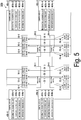
- Fig. 5 is a diagram illustrating a configuration of a communication system 100b according to a third embodiment.
- the communication system 100b includes a plurality of master station devices 10 (10-1 to 10-6), a plurality of slave station devices 20 (20-1 to 20-6), a plurality of transfer devices 30 (30-1 to 30-4), and a plurality of control devices 40b (40b-1 to 40b-4).
- the control device 40b is connected to the master station devices 10-1 to 10-6 and the slave station devices 20-1 to 20-6.
- control device 40b-1 is connected to the master station devices 10-1 to 10-3
- control device 40b-2 is connected to the master station devices 10-4 to 10-6
- control device 40b-3 is connected to the slave station devices 20-1 to 20-3
- control device 40b-4 is connected to the slave station devices 20-4 to 20-6.
- the control devices 40b are disposed to be distributed in plural (for example, four), and the plurality of control devices 40b share information included in each of the plurality of control devices 40b to control the master station devices 10 and the slave station devices 20.
- control device 40b Next, a functional configuration of the control device 40b will be described. Note that the control devices 40b-1 to 40b-4 have the same configuration except that their connecting devices are different. For this reason, description will be given by collectively referring to the control devices 40b-1 to 40b-4 as the control device 40b.
- the control device 40b includes a CPU, a memory, an auxiliary storage device, and the like which are connected to each other by a bus, and executes a control program.
- the control device 40b functions as a device including an information acquisition unit 401b, a switching control unit 402b, an information storage unit 403b, and an information sharing unit 404b by executing the control program.
- all or some functions of the control device 40a may be realized using hardware such as an ASIC, a PLD, or an FPGA.
- the control program may be recorded in a computer-readable recording medium.
- the computer-readable recording medium is, for example, a portable medium such as a flexible disk, a magneto-optical disk, a ROM or a CD-ROM, or a storage device such as a hard disk drive built into a computer system.
- the control program may be transmitted and received through an electrical communication line.
- the information acquisition unit 401b acquires information regarding traffic by monitoring traffic of data transmitted and received between the master station device 10 and the slave station device 20. Specifically, the information acquisition unit 401b acquires the amount of traffic from the master station devices 10 to the slave station devices 20 in a downlink and the amount of traffic from the slave station devices 20 to the master station devices 10 in an uplink.
- the switching control unit 402b performs switching-control of an assignment relationship of either the master station device 10 or the slave station device 20 and switching-control of a transfer path of data between the master station device 10 and the slave station device 20, in accordance with traffic detected by the information acquisition unit 401b. Specifically, in a case where the control device 40b is connected to the master station device 10 and is not connected to the slave station device 20, the switching control unit 402b performs switching-control of an assignment relationship and switching-control of a transfer path of data on the master station device 10.
- the switching control unit 402b performs switching-control of an assignment relationship and switching-control of a transfer path of data on the slave station device 20.
- the information storage unit 403b stores connection device information.
- Information regarding a device (for example, the master station devices 10-1 to 10-3) to which a certain control device 40b (for example, the control device 40b-1) is connected and information regarding a device (for example, a device other than the master station devices 10-1 to 10-3) to which another control device 40b (for example, the control device 40b other than the control device 40b-1) acquired by the information sharing unit 404b is connected are stored in the information storage unit 403b as the connection device information.
- the information sharing unit 404b shares information with other control devices 40b.
- the information sharing unit 404b transmits the connection device information stored in the information storage unit 403b of the control devices 40b to the other control devices 40b, and shares information by receiving the connection device information from the other control devices 40b.
- the information sharing unit 404b stores the received connection device information in the information storage unit 403b.
- a timing at which the information sharing unit 404b shares information may be a preset timing or may be a timing at which information of the amount of traffic is acquired.
- the control device 40b performs switching-control of an assignment relationship and switching-control of a transfer path of data as follows.
- the switching control unit 402b-1 performs switching-control of an assignment relationship and switching-control of a transfer path of data on the master station devices 10-1 to 10-3.
- the switching control unit 402b-2 performs switching-control of an assignment relationship and switching-control of a transfer path of data on the master station devices 10-4 to 10-6.
- the switching control unit 402b-3 performs switching-control of an assignment relationship and switching-control of a transfer path of data on the slave station devices 20-1 to 20-3.
- the switching control unit 402b-4 performs switching-control of an assignment relationship and switching-control of a transfer path of data on the slave station devices 20-1 to 20-3.
- a method of performing switching-control of an assignment relationship and switching-control of a transfer path of data is the same as that in the first embodiment, and thus description thereof will be omitted.
- switching-control of an assignment relationship and switching-control of a transfer path of data are performed on all of the master station devices 10 and the slave station devices 20 by one control device 40.
- each of the plurality of control devices 40b configured as described above performs switching-control of an assignment relationship and switching-control of a transfer path of data only on a device to which the control devices 40b is connected. Thereby, it is possible to reduce a processing load generated in one control device 40b.
- processing resources of the master station device 10 can be effectively utilized.
- An object to be monitored by the information acquisition unit 401b may be a QoS value of traffic rather than the amount of traffic.
- a high-level control device connected to the plurality of control devices 40b-1 to 40b-4 may be configured to acquire all pieces of information and transmit an instruction for control to each of the control devices 40b-1 to 40b-4 on the basis of the acquired information.
- the control device 40b may be configured to be also connected to the transfer device 30 as in the second embodiment.
- Fig. 6 is a diagram illustrating another configuration of the communication system 100b according to the third embodiment.
- the communication system 100b illustrated in Fig. 6 includes a plurality of master station devices 10 (10-1 to 10-6), a plurality of slave station devices 20 (20-1 to 20-6), a plurality of transfer devices 30 (30-1 to 30-4), and a plurality of control devices 40b (40b-1 to 40b-8).
- the control device 40b is connected to the master station devices 10-1 to 10-6, the slave station devices 20-1 to 20-6, and the transfer device 30.
- control device 40b-5 is connected to the transfer device 30-1, the control device 40b-6 is connected to the transfer device 30-2, the control device 40b-7 is connected to the transfer device 30-3, and the control device 40b-8 is connected to the transfer device 30-4.
- the control devices 40b are disposed to be distributed in plural (for example, eight), and the plurality of control devices 40b share information included in each of the plurality of control devices 40b to control the master station devices 10, the slave station devices 20, and the transfer devices 30.
- the third embodiment differs from the second embodiment in that the control devices 40b-5 to 40b-8 are individually installed for the respective transfer devices 30-1 to 30-4, and the control devices 40b-5 to 40b-8 perform control only on the transfer devices 30-1 to 30-4 to which each of the control devices 40b-5 to 40b-8 is connected.
- Specific control processing is the same as that in the second embodiment, and thus description thereof will be omitted.
- Fig. 7 is a diagram illustrating a configuration of a communication system 100c according to a fourth embodiment.
- the communication system 100c includes a plurality of master station devices 10 (10-1 to 10-6), a plurality of slave station devices 20 (20-1 to 20-6), a plurality of transfer devices 30 (30-1 to 30-4), and a control device 40c.
- the control device 40c is connected to all of the master station devices 10-1 to 10-6, the slave station devices 20-1 to 20-6, and the transfer devices 30-1 to 30-4.
- the control device 40c executes switching-control of an assignment relationship and switching-control of a transfer path of data in the first to third embodiments in combination.
- the control device 40c may monitor the amount of traffic as in the first embodiment, transmit an instruction for performing switching-control of a transfer path of data to the transfer device 30 as in the second embodiment, acquire information of the amount of traffic from the transfer device 30 as in the second embodiment, and transmit an instruction for performing switching-control of a transfer path of data to the master station device 10 and the slave station device 20 as in the first embodiment.
- the control device 40c may be configured to be distributed in plural and share information as in the third embodiment, instead of as one device as illustrated in Fig. 7 .
- control device 40c Next, a functional configuration of the control device 40c will be described.
- the control device 40c includes a CPU, a memory, an auxiliary storage device, and the like which are connected to each other by a bus, and executes a control program.
- the control device 40c functions as a device including an information acquisition unit 401c, a switching control unit 402c, an information storage unit 403c, and an information sharing unit 404c by executing the control program.
- all or some functions of the control device 40c may be realized using hardware such as an ASIC, a PLD, or an FPGA.
- the control program may be recorded in a computer-readable recording medium.
- the computer-readable recording medium is, for example, a portable medium such as a flexible disk, a magneto-optical disk, a ROM or a CD-ROM, or a storage device such as a hard disk drive built into a computer system.
- the control program may be transmitted and received through an electrical communication line.
- the information acquisition unit 401c performs the same processes as those of the information acquisition units 401, 401a, and 401b in the first to third embodiments. Note that whether to perform the same processing as that of any one of the information acquisition units 401, 401a, and 401b is appropriately set.
- the switching control unit 402c performs the same processes as those of the switching control units 402, 402a, and 402b in the first to third embodiments. Note that whether to perform the same processing as that of any one of the switching control units 402, 402a, and 402b is appropriately set.
- the information storage unit 403c stores connection device information.
- the information sharing unit 404c performs the same processing as that of the information sharing unit 404b.
- control device 40c configured as described above can obtain the same effect as in the first to third embodiments.
- control device 40c can perform a plurality of controls for switching-control of an assignment relationship and switching-control of a transfer path of data. Thereby, the control device 40c can perform more suitable control depending on the situation. For this reason, it is possible to improve convenience.
- the communication system 100c according to the fourth embodiment may be modified in the same manner as in the first to third embodiments.
- Fig. 8 is a diagram illustrating a configuration of a communication system 100d according to a fifth embodiment.
- the communication system 100d includes a plurality of master station devices 10 (10-1 and 10-4 to 10-6), a plurality of slave station devices 20 (20-1 to 20-6), a plurality of transfer devices 30 (30-1 to 30-4), and a control device 40d.
- the control device 40d is connected to the master station devices 10-1 to 10-6 and the slave station devices 20-1 to 20-6.
- the fifth embodiment is an embodiment corresponding to a case where the plurality of slave station devices 20 are assigned to one master station device 10 through the processing of any one of the first to fourth embodiments or a case where the plurality of slave station devices 20 are assigned to one master station device 10 before the processing of the first to fourth embodiments is performed.
- control device 40d Next, a functional configuration of the control device 40d will be described.
- the control device 40d includes a CPU, a memory, an auxiliary storage device, and the like connected to each other through a bus and executes a control program.
- the control device 40d functions as a device including an information acquisition unit 401, a switching control unit 402d, and an information storage unit 403 by executing the control program.
- all or some functions of the control device 40d may be realized using hardware such as an ASIC, a PLD, or an FPGA.
- the control program may be recorded in a computer-readable recording medium.
- the computer-readable recording medium is, for example, a portable medium such as a flexible disk, a magneto-optical disk, a ROM or a CD-ROM, or a storage device such as a hard disk drive built into a computer system.
- the control program may be transmitted and received through an electrical communication line.
- the control device 40d differs in configuration from the control devices 40, 40a, 40b, and 40c according to the other embodiments in that the control device 40d includes the switching control unit 402d.
- the control device 40d is the same as the control devices 40, 40a, 40b, and 40c for the other configurations. For this reason, the switching control unit 402d will be described.
- the switching control unit 402d performs the same processing as the switching control unit 402. A difference between processing performed by the switching control unit 402d and processing performed by the switching control unit 402 is switching-control of an assignment relationship.
- the switching control unit 402d performs switching-control of an assignment relationship on the master station device 10 and the slave station device 20 so as to make the plurality of slave station devices 20 assigned to one master station device 10 be assigned to other master station devices 10.
- Fig. 9 is a flowchart illustrating a flow of processing of the control device 40d according to the fifth embodiment.
- the information acquisition unit 401 acquires the amount of traffic of the master station devices 10 by monitoring traffic of data transmitted and received between the master station devices 10 and the slave station devices 20 (step S201).
- the information acquisition unit 401 outputs the information of the acquired amount of traffic to the switching control unit 402.
- the switching control unit 402d determines whether or not traffic to be processed by one master station device 10 exceeds processing resources of one master station device 10 on the basis of the information of the amount of traffic output from the information acquisition unit 401 and connection device information stored in the information storage unit 403 (step S202). Specifically, the switching control unit 402d first acquires processing resources of a certain master station device 10 (for example, the master station device 10-1) with reference to the connection device information. Next, the switching control unit 402d compares the acquired processing resources with the sum of the amounts of traffic of the slave station devices 20 (for example, the slave station devices 20-1 to 20-3) belonging to a certain master station device 10 (for example, the master station device 10-1).
- the switching control unit 402d determines that traffic to be processed by one master station device 10 exceeds processing resources of one master station device 10. On the other hand, in a case where the sum of the amounts of traffic does not exceed the processing resources, the switching control unit 402d determines that traffic to be processed by one master station device 10 does not exceed the processing resources of one master station device 10.
- control device 40d terminates the processing of Fig. 9 .
- the switching control unit 402d performs switching-control of an assignment relationship (step S203). Specifically, the switching control unit 402d instructs the master station device 10 and the slave station device 20 for which switching of an assignment relationship is to be performed to switch an assignment relationship.
- the switching control unit 402d instructs the master station device 10-1 to perform switching for cancelling the assignment of the slave station devices 20-2 and 20-3 to the master station device 10-1, instructs the slave station devices 20-2 and 20-3 to perform switching for belonging to other master station devices 10, and instructs other master station devices 10 to perform switching for the assignment of the slave station devices 20-2 and 20-3 to the other master station devices 10.
- other master station devices 10 are, for example, master station devices 10 to which other slave station devices 20 are not assigned or master station devices 10 having a margin of processing resources even when the slave station devices 20 are assigned to the master station devices 10.
- the switching control unit 402d instructs the slave station device 20-2 to perform switching for belonging to the master station device 10-2, instructs the slave station device 20-3 to perform switching for belonging to the master station device 10-3, instructs the master station device 10-2 to perform switching for making the slave station device 20-2 are assigned to the master station device 10-2, and instructs the master station device 10-2 to perform switching for making the slave station device 20-2 are assigned to the master station device 10-2.
- the master station devices 10-1 to 10-3 and the slave station devices 20-1 to 20-3 change their own setting.
- the master station device 10-1 cancels an assignment relationship between the slave station devices 20-2 and 20-3.
- the slave station device 20-2 changes the setting of the slave station device 20-2 so as to be assigned to the master station device 10-2.
- the master station device 10-2 changes the setting of the master station device 10-2 so as to make the slave station device 20-2 be assigned to the master station device 10-2.
- the slave station device 20-3 changes the setting of the slave station device 20-3 so as to be assigned to the master station device 10-3.
- the master station device 10-3 changes the setting of the master station device 10-3 so as to make the slave station device 20-3 be assigned to the master station device 10-3.
- the switching control unit 402d performs switching-control of a transfer path (step S204). Specifically, the switching control unit 402d performs switching-control of a transfer path so that data is transmitted and received to and from a device after an assignment relationship is changed. For example, in the above-described example, the switching control unit 402d switches a transfer path so that data is transmitted and received between the master station device 10-2 and the slave station device 20-2 and between the master station device 10-3 and the slave station device 20-3.
- the switching control unit 402d performs switching-control of a transfer path by transmitting, to the master station device 10 and the slave station device 20, an instruction for changing a destination address of a frame to be transmitted in the master station device 10 and the slave station device 20.
- the switching control unit 402d transmits an instruction for setting a destination address of data to be an address of the slave station device 20-1 to the master station device 10-1.
- the switching control unit 402d transmits an instruction for setting a destination address of data to be an address of the master station device 10-2 to the slave station device 20-2 and transmits an instruction for setting a destination address of data to be an address of the slave station device 20-2 to the master station device 10-2.
- the switching control unit 402d transmits an instruction for setting a destination address of data to be an address of the master station device 10-3 to the slave station device 20-3 and transmits an instruction for setting a destination address of data to be an address of the slave station device 20-3 to the master station device 10-3.
- the slave station device 20-2 sets a destination address of data to be the master station device 10-2.
- the slave station device 20-3 sets a destination address of data to be the master station device 10-3.
- the master station device 10-2 sets a destination address of data to be the slave station device 20-2.
- the master station device 10-3 sets a destination address of data to be the slave station device 20-3.
- Fig. 10 is a diagram illustrating a configuration of the communication system 100 after switching control according to the fifth embodiment.
- a transfer path is switched such that data is transmitted and received between the master station device 10-1 and the slave station device 20-1, between the master station device 10-2 and the slave station device 20-2, and between the master station device 10-3 and the slave station device 20-3, and control is performed such that data of the slave station device 20-2 and the slave station device 20-3 is not transmitted and received to and from the master station device 10-1.
- traffic that cannot be processed by only the master station device 10-1 can be processed, and processing resources of the master station devices 10-1 to 10-3 can be effectively utilized.
- control device 40 configured as described above disperses traffic by causing the slave station devices 20 to be assigned to other master station devices 10. Thereby, all traffic can be processed, and processing resources of the master station devices 10 can be effectively utilized.
- An object to be monitored by the information acquisition unit 401 may be a QoS value of traffic rather than the amount of traffic.
- the switching control unit 402d may be configured to execute the process of step S203 and the subsequent processes in a case where traffic to be processed by one master station device 10 exceeds a predetermined percentage (for example, 80 %) of processing resources of one master station device 10.
- a predetermined percentage for example, 80 % of processing resources of one master station device 10.
- control device 40d may be connected to all of the master station devices 10-1 to 10-6, the slave station devices 20-1 to 20-6, and the transfer devices 30-1 to 30-4 to give an instruction for performing switching-control of a transfer path of data to the transfer device 30 as in the second embodiment.
- switching-control of an assignment relationship and switching-control of a transfer path of data may be performed using a method of any one of the first to fourth embodiments.
- the numbers of the master station devices 10 and 10a and the numbers of the slave station devices 20 and 20a are not necessarily limited to the above-described numbers as long as the numbers are two or more.
- the numbers of the transfer devices 30 and 30a are not necessarily limited to the above-described numbers as long as the numbers are one or more.
Landscapes
- Engineering & Computer Science (AREA)
- Computer Networks & Wireless Communication (AREA)
- Signal Processing (AREA)
- Small-Scale Networks (AREA)
- Data Exchanges In Wide-Area Networks (AREA)
Abstract
Description
- The present disclosure relates to a control apparatus and a control method.
- In the related art, in a wireless communication system, and particularly in a mobile communication system, a Centralized-Radio Access Network (C-RAN) configuration in which a base station device (base station apparatus) constituted by one device, as disclosed in, for example,
Non Patent Literature 1, is divided into two devices, a master station device (master station apparatus) and a slave station device (slave station apparatus), has been examined in order to increase flexibility in installing a base station. -
Fig. 11 is a diagram illustrating a configuration of acommunication system 1 of C-RAN in the related art. As illustrated inFig. 11 , in the configuration of thecommunication system 1 of C-RAN in the related art, master station devices 101 (101-1 to 101-3) and slave station devices 201 (201-1 to 201-3) are connected to each other on a one-to-one basis, and the plurality of master station devices 101-1 to 101-3 are aggregated at one location. For example, inFig. 11 , the master station device 101-1 is connected to the slave station device 201-1, the master station device 101-2 is connected to the slave station device 201-2, and the master station device 101-3 is connected to the slave station device 201-3. - However, in C-RAN in the related art in which Physical (PHY) layer functions including a baseband signal processing function are aggregated into the master station device 101 to transmit IQ data of a wireless signal, an increase in the amount of transmission data between the master station device 101 and the slave station device 201 has become a problem.
- Consequently, as in
Non Patent Literature 2, a technique for reducing the amount of transmission data by redefining the division of functions of a master station device and a slave station device has been examined. Division points in the redefinition of the division of functions include a plurality of candidates. A master station device and a slave station device are constituted by a Packet Data Convergence Protocol (PDCP) layer, a Radio Link Control (RLC) layer, a Media Access Control (MAC) layer, and a PHY layer. - Among the division points, a division point having a function of a PDCP layer in a master station device and having functions of an RLC layer and layers below the RLC layer in a slave station device is referred to as a Higher Layer Split (HLS). In an HLS, the amount of transmission data between a master station device and a slave station device is smaller than that of C-RAN in the related art, and a delay request also becomes less severe.
- On the other hand, function division having functions of a MAC layer and layers above the MAC layer or functions of an upper PHY layer and layers above the PHY layer in the master station device, and having the other functions in the slave station device, is referred to as a lower layer split (LLS). In an LLS, the amount of transmission data and a delay request are close to those of C-RAN in the related art, but a high base station association performance can be maintained, which is one of the advantages of C-RAN in the related art.
- In either an HLS or an LLS, signal data between a master station device and a slave station device can be transmitted and received by an Ethernet (trade name) frame due to the redefinition of the function division. Thus, it is assumed that a transfer device (transfer apparatus) such as a switch, for example, is installed between the master station device and the slave station device.
Fig. 12 is a diagram illustrating a configuration of acommunication system 2 in which a transfer device is installed. In the drawing illustrated inFig. 12 , atransfer device 302 is installed between master station devices 102 (102-1 to 102-3) and slave station devices 202 (202-1 to 202-3). Thetransfer device 302 is a device that transfers data transmitted and received between the master station devices 102 (102-1 to 102-3) and the slave station devices 202 (202-1 to 202-3). Thetransfer device 302 is, for example, a switch. - It is also assumed that a network is constructed by installing a plurality of transfer devices between the master station devices and the slave station devices.
Fig. 13 is a diagram illustrating a configuration of acommunication system 3 in which a plurality of transfer devices are installed. In the drawing illustrated inFig. 13 , a plurality of transfer devices 303 (303-1 to 303-4) are installed between master station devices 103 (103-1 to 103-6) and slave station devices 203 (203-1 to 203-6). The transfer devices 303 are devices that transfer data transmitted and received between the master station devices 103 (103-1 to 103-6) and the slave station devices 203 (203-1 to 203-3). The transfer device 303 is, for example, a switch. Also in the cases ofFigs. 12 and13 , the master station devices and the slave station devices are logically connected to each other on a one-to-one basis. -
- Non Patent Literature 1: Kohei Kiyoshima and three others, "LTE-Advanced commercial development utilizing advanced C-RAN architecture - Achievement of stable communication by capacity expansion based on add-on cell and advanced inter-cell association -," NTT DOCOMO Technical Journal Vol. 23, No. 2, pp. 11-18.
- Non Patent Literature 2: Anil Umesh and four others, "5G radio access network standardization trend," NTT DOCOMO Technical Journal Vol. 25, No. 3, pp. 33-43.
- In a case where master station devices and slave station devices are logically connected to each other on a one-to-one basis, processing resources of the master station devices will be used exclusively even when the amount of traffic to be processed by the slave station devices is small, and thus a large amount of processing resources of the master station devices is wasted. On the other hand, in a case where the amount of traffic of the slave station devices which are to be processed by the master station devices is excessively large, processing resources of the master station devices are insufficient. In this manner, in a case where a network is constructed between the master station devices and the slave station devices, there is a problem in that processing resources of the master station devices cannot be effectively utilized.
- In view of the above-described circumstances, an object of the present disclosure is to provide a technique making it possible to effectively utilize processing resources of a master station apparatus in a case where a network having a transfer apparatus disposed between the master station apparatus and a slave station apparatus is constructed.
- An aspect of the present disclosure is a control apparatus that controls any one or all of a plurality of slave station apparatuses, a plurality of master station apparatuses, and a transferapparatus, a slave station apparatus of the plurality of slave station apparatuses being assigned to a master station apparatus of the plurality of master station apparatuses, the master station apparatus controlling the slave station apparatus, and the transfer apparatus transferring data transmitted and received between the master station apparatus and the slave station apparatus, the control apparatus including an information acquisition unit that acquires information regarding traffic of the data transmitted and received between the master station apparatus and the slave station apparatus, and a switching control unit that performs, on the basis of the information regarding the traffic acquired by the information acquisition unit, switching-control of an assignment relationship between the master station apparatus and the slave station apparatus and switching-control of a transfer path of data between the master station apparatus and the slave station apparatus.
- In the control apparatus according to the aspect of the present disclosure, in a case where traffic of another slave station apparatus of the plurality of slave station apparatuses that is assigned to another master station apparatus of the plurality of master station apparatuses is able to be processed in one master station apparatus of the plurality of master station apparatuses, the switching control unit performs switching-control of an assignment relationship to assign the other slave station apparatus assigned to the other master station apparatus to the one master station apparatus, and performs switching-control of a transfer path of data by instructing the other slave station apparatus to set destinations of data transmitted from the other slave station apparatuses assigned to the other master station apparatus to be a destination of the one master station apparatus.
- In the control apparatus according to the aspect of the present disclosure, in a case where traffic of another slave station apparatus of the plurality of slave station apparatuses that is assigned to another master station apparatus of the plurality of master station apparatuses is able to be processed in one master station apparatus of the plurality of master station apparatuses, the switching control unit performs switching-control of an assignment relationship to assign the other slave station apparatus assigned to the other master station apparatus to the one master station apparatus, and performs switching-control of a transfer path of data by instructing the transfer apparatus to set destinations of data transmitted from the other slave station apparatuses assigned to the other master station apparatus to be a destination of the one master station apparatus.
- The control apparatus according to the aspect of the present disclosure further includes an information sharing unit that shares, with another control apparatus, information regarding any one or all of the master station apparatus, the slave station apparatus, and the transfer apparatus that are not connected to the control apparatus, in which the switching control unit performs the switching-control of the assignment relationship and the switching-control of the transfer path of data on any one apparatus of the master station apparatus, the slave station apparatus, and the transfer apparatus that are connected to the control apparatus, using the information shared with the other control apparatus by the information sharing unit.
- In the control apparatus according to the aspect of the present disclosure, in a case where traffic of a plurality of slave station apparatuses assigned to one master station apparatus of the plurality of master station apparatuses is equal to or greater than a predetermined percentage of processing resources of the one master station apparatus, the switching control unit performs switching-control of an assignment relationship to assign a slave station apparatus which is a target for switching, among the plurality of slave station apparatuses assigned to the one master station apparatus, to another master station apparatus of the plurality of master station apparatuses, and performs switching-control of a transfer path of data by instructing the slave station apparatus which is a target for switching, among the plurality of slave station apparatuses assigned to the one master station apparatus, to set a destination of data transmitted from the slave station apparatus which is a target for switching to be a destination of the other master station apparatus.
- In the control apparatus according to the aspect of the present disclosure, in a case where traffic of a plurality of slave station apparatuses assigned to one master station apparatus of the plurality of master station apparatuses is equal to or greater than a predetermined percentage of processing resources of the one master station apparatus, the switching control unit performs switching-control of an assignment relationship to assign a slave station apparatus which is a target for switching, among the plurality of slave station apparatuses assigned to the one master station apparatus, to another master station apparatus of the plurality of master station apparatuses, and performs switching-control of a transfer path of data by instructing the transfer apparatus to set a destination of data transmitted from the slave station apparatus which is a target for switching, among the plurality of slave station apparatuses assigned to the one master station apparatus, to be a destination of the other master station apparatus.
- Another aspect of the present disclosure is a control method performed by a control apparatus that controls any one or all of a plurality of slave station apparatuses, a plurality of master station apparatuses, and a transfer apparatus, a slave station apparatus of the plurality of slave station apparatuses being assigned to a master station apparatus of the plurality of master station apparatuses, the master station apparatus controlling the slave station apparatus, the transfer apparatus transferring data transmitted and received between the master station apparatus and the slave station apparatus, the control method including acquiring information regarding traffic of the data transmitted and received between the master station apparatus and the slave station apparatus, and performing, on the basis of the information regarding the traffic acquired in the acquiring of the information, switching-control of an assignment relationship between the master station apparatus and the slave station apparatus and switching-control of a transfer path of data between the master station apparatus and the slave station apparatus.
- According to the present disclosure, it is possible to effectively utilize processing resources of master station apparatuses in a case where a network having a transfer apparatus disposed between the master station apparatus and a slave station apparatus is constructed.
-
-
Fig. 1 is a diagram illustrating a configuration of a communication system according to a first embodiment. -
Fig. 2 is a flowchart illustrating a flow of processing of a control device according to the first embodiment. -
Fig. 3 is a diagram illustrating a configuration of the communication system after switching control according to the first embodiment. -
Fig. 4 is a diagram illustrating a configuration of a communication system according to a second embodiment. -
Fig. 5 is a diagram illustrating a configuration of a communication system according to a third embodiment. -
Fig. 6 is a diagram illustrating another configuration of the communication system according to the third embodiment. -
Fig. 7 is a diagram illustrating a configuration of a communication system according to a fourth embodiment. -
Fig. 8 is a diagram illustrating a configuration of a communication system according to a fifth embodiment. -
Fig. 9 is a flowchart illustrating a flow of processing of a control device according to the fifth embodiment. -
Fig. 10 is a diagram illustrating a configuration of the communication system after switching control according to the fifth embodiment. -
Fig. 11 is a diagram illustrating a configuration of a communication system of C-RAN in the related art. -
Fig. 12 is a diagram illustrating a configuration of a communication system in which a transfer device is installed. -
Fig. 13 is a diagram illustrating a configuration of a communication system in which a plurality of transfer devices are installed. - Embodiments of the present disclosure will be described below with reference to the drawings.
-
Fig. 1 is a diagram illustrating a configuration of acommunication system 100 according to a first embodiment. Thecommunication system 100 includes a plurality of master station devices (master station apparatuses) 10 (10-1 to 10-6), a plurality of slave station devices (slave station apparatuses) 20 (20-1 to 20-6), a plurality of transfer devices (transfer apparatuses) 30 (30-1 to 30-4), and a control device (control apparatus) 40. - In
Fig. 1 , the master station devices 10-1 to 10-3 are connected to the transfer device 30-1. The master station devices 10-4 to 10-6 are connected to the transfer device 30-2. The slave station devices 20-1 to 20-3 are connected to the transfer device 30-3. The slave station devices 20-4 to 20-6 are connected to the transfer device 30-4. In addition, thecontrol device 40 is connected to the master station devices 10-1 to 10-6 and the plurality of slave station devices 20-1 to 20-6. - The transfer device 30-1 is connected to the transfer device 30-2 and the transfer device 30-3 in addition to the master station devices 10-1 to 10-3. The transfer device 30-2 is connected to the transfer device 30-1 and the transfer device 30-4 in addition to the master station devices 10-4 to 10-6. The transfer device 30-3 is connected to the transfer device 30-1 and the transfer device 30-4 in addition to the slave station devices 20-1 to 20-3. The transfer device 30-4 is connected to the transfer device 30-2 and the transfer device 30-3 in addition to the slave station devices 20-4 to 20-6.
- In addition, arrows 50-1 to 50-6 illustrated in
Fig. 1 indicate transfer paths of data. For example, the arrow 50-1 represents a transfer path of data from the master station device 10-1 to the slave station device 20-1 in a downlink, and a transfer path of data from the slave station device 20-1 to the master station device 10-1 in an uplink. - The master station device 10 controls the slave station device 20 assigned to the master station device 10. The master station devices 10 and the slave station devices 20 are logically connected to each other on a one-to-one basis. For example, the slave station device 20-1 is assigned to the master station device 10-1, the slave station device 20-2 is assigned to the master station device 10-2, the slave station device 20-3 is assigned to the master station device 10-3, the slave station device 20-4 is assigned to the master station device 10-4, the slave station device 20-5 is assigned to the master station device 10-5, and the slave station device 20-6 is assigned to the master station device 10-6.
- The master station device 10 stores information regarding the slave station device 20 assigned to the master station device 10. The information regarding the slave station device 20 is information for identifying the slave station device 20 and is, for example, a MAC address of the slave station device 20, or the like. The master station device 10 transmits and receives data to and from the slave station device 20 assigned to the master station device 10 in a case where control is not performed by the
control device 40. In a case where control is performed by thecontrol device 40, the master station device 10 changes an assignment relationship and transmits and receives data to and from the slave station device 20 instructed by thecontrol device 40. - The slave station device 20 communicates with a terminal device not illustrated in the drawing. The slave station device 20 transmits and receives data to and from the master station device 10 to which the slave station device 20 is assigned in a case where control is not performed by the
control device 40. In a case where control is performed by thecontrol device 40, the slave station device 20 changes an assignment relationship and transmits and receives data to and from the master station device 10 instructed by thecontrol device 40. - The transfer device 30 transfers data transmitted and received between the master station device 10 and the slave station device 20 to a destination included in the data. The transfer device 30 is, for example, a switch.
- The
control device 40 controls the master station device 10 and the slave station device 20. Specifically, thecontrol device 40 performs switching-control of an assignment relationship between the master station device 10 and the slave station device 20, and switching-control of a transfer path of data between the master station device 10 and the slave station device 20. - Next, a functional configuration of the
control device 40 will be described. - The
control device 40 includes a central processing unit (CPU), a memory, an auxiliary storage device, and the like connected to each other through a bus and executes a control program. Thecontrol device 40 functions as a device including aninformation acquisition unit 401, a switchingcontrol unit 402, and aninformation storage unit 403 by executing the control program. Note that all or some functions of thecontrol device 40 may be realized using hardware such as an application specific integrated circuit (ASIC), a programmable logic device (PLD), or a field programmable gate array (FPGA). In addition, the control program may be recorded in a computer-readable recording medium. The computer-readable recording medium is, for example, a portable medium such as a flexible disk, a magneto-optical disk, a ROM or a CD-ROM, or a storage device such as a hard disk drive built into a computer system. In addition, the control program may be transmitted and received through an electrical communication line. - The
information acquisition unit 401 acquires information regarding traffic by monitoring traffic of data transmitted and received between the master station device 10 and the slave station device 20. The information regarding traffic is, for example, information of the amount of traffic. Specifically, theinformation acquisition unit 401 acquires the amount of traffic from the master station devices 10-1 to 10-6 to the slave station devices 20-1 to 20-6 in a downlink and the amount of traffic from the slave station devices 20-1 to 20-6 to the master station devices 10-1 to 10-6 in an uplink. - The switching
control unit 402 performs switching-control of an assignment relationship between the master station device 10 and the slave station device 20 and switching-control of a transfer path of data between the master station device 10 and the slave station device 20 in response to traffic detected by theinformation acquisition unit 401. - The
information storage unit 403 stores information regarding a device to which thecontrol device 40 is connected (hereinafter referred to as "connection device information"). For example, theinformation storage unit 403 stores processing resources of the master station device 10 and information of the slave station device 20 assigned to the master station device 10, for each master station device 10. In addition, for example, theinformation storage unit 403 stores information of the master station device 10 to which the slave station device 20 is assigned for each slave station device 20. Theinformation storage unit 403 is constituted using a storage device such as a magnetic hard disk device or a semiconductor storage device. -
Fig. 2 is a flowchart illustrating a flow of processing of thecontrol device 40 according to the first embodiment. - The
information acquisition unit 401 acquires the amount of traffic of each of the master station devices 10 by monitoring traffic of data transmitted and received between the master station device 10 and the slave station device 20 (step S101). For example, theinformation acquisition unit 401 may monitor traffic output from the master station device 10 to acquire the amount of traffic of each of the master station devices 10, or may monitor traffic input from the master station device 10 to acquire the amount of traffic of each of the master station devices 10. Theinformation acquisition unit 401 outputs information of the acquired amount of traffic to the switchingcontrol unit 402. - The switching
control unit 402 determines whether there is a master station device 10 capable of processing the slave station device 20 assigned to another master station device 10 on the basis of the information of the amount of traffic which is output from theinformation acquisition unit 401 and the connection device information stored in the information storage unit 403 (step S102). Specifically, the switchingcontrol unit 402 adds the amount of traffic of the slave station device 20 assigned to a certain master station device 10 and the amount of traffic of at least one slave station device 20 among the plurality of slave station devices 20 assigned to other master station devices 10, and determines that there is a master station device 10 capable of processing the slave station device 20 assigned to another master station device 10 in a case where the sum does not exceed processing resources of the master station device 10. - For example, the switching
control unit 402 adds the amount of traffic of the slave station device 20-1 assigned to the master station device 10-1 and the amount of traffic of the slave station device 20-2 assigned to the other master station device 10-2, and determines that there is a master station device 10 capable of processing the slave station device 20-2 assigned to the other master station device 10-2 in a case where the sum does not exceed processing resources of the master station device 10-1. - On the other hand, in a case where the sum exceeds the processing resources of the master station device 10, it is determined that there is no master station device 10 capable of processing the slave station device 20 assigned to another master station device 10.
- In a case where there is no master station device 10 capable of processing the slave station device 20 assigned to another master station device 10 (step 102-NO), the
control device 40 terminates the processing ofFig. 2 . - On the other hand, in a case where there is a master station device 10 capable of processing the slave station device 20 assigned to another master station device 10 (step 102-YES), the switching
control unit 402 performs switching-control of an assignment relationship (step S103). Specifically, the switchingcontrol unit 402 instructs the master station device 10 and the slave station device 20 which are targets for switching of an assignment relationship to switch the assignment relationship. - For example, in a case where the amount of traffic flowing to the slave station devices 20-1 to 20-3 is small and capable of being processed by the master station device 10-1, the switching
control unit 402 gives an instruction for switching an assignment relationship so that all of the slave station devices 20-1 to 20-3 are assigned to the master station device 10-1. In addition, the switchingcontrol unit 402 instructs the master station devices 10-1 to 10-3 to switch an assignment relationship so that all of the slave station devices 20-1 to 20-3 are assigned to the master station device 10-1. Thereby, the master station devices 10-1 to 10-3 and the slave station devices 20-1 to 20-3 change their own setting. In this case, the master station device 10-2 cancels an assignment relationship with the slave station device 20-2, and the master station device 10-3 cancels an assignment relationship with the slave station device 20-3. The slave station devices 20-1 to 20-3 change the setting of the slave station devices 20-1 to 20-3 to be assigned to the master station device 10-1. The master station device 10-1 changes the setting of the master station device 10-1 to assign the slave station devices 20-1 to 20-3 to the master station device 10-1. - Thereafter, the switching
control unit 402 performs switching-control of a transfer path (step S104). - Specifically, the switching
control unit 402 performs switching-control of a transfer path so that data is transmitted and received to and from the device after an assignment relationship is changed. For example, in the above-described example, the switchingcontrol unit 402 switches a transfer path so that data is transmitted and received between the master station device 10-1 and the slave station devices 20-1 to 20-3. - The switching
control unit 402 performs switching-control of a transfer path by transmitting, to the master station device 10 and the slave station device 20, an instruction for changing a destination address of a frame to be transmitted in the master station device 10 and the slave station device 20. For example, the switchingcontrol unit 402 transmits an instruction for setting a destination address of data to be the master station device 10-1 for the slave station devices 20-1 to 20-3 and transmits an instruction for setting a destination address of data to be the slave station devices 20-1 to 20-3 for the master station device 10-1. Thereby, the slave station devices 20-1 to 20-3 set a destination address of data to be the master station device 10-1. In addition, the master station device 10-1 sets a destination address of data to be any one of the slave station devices 20-1 to 20-3. -
Fig. 3 is a diagram illustrating a configuration of thecommunication system 100 after switching control according to the first embodiment. - As illustrated in
Fig. 3 , after the switching control is performed, a transfer path is switched such that data is transmitted and received between the master station device 10-1 and the slave station devices 20-1 to 20-3, and control is performed such that data is not transmitted and received to and from the master station devices 10-2 and 10-3. Thereby, the master station devices 10-2 and 10-3 do not need to operate, and processing resources are freed up. - The
control device 40 configured as described above performs switching-control of an assignment relationship between the master station device 10 and the slave station device 20 in accordance with traffic of data transmitted and received between the master station device 10 and the slave station device 20. In the switching-control, when traffic of the slave station devices 20 assigned to other master station devices 10 can be processed by one master station device 10, the slave station devices are assigned to the master station device 10 capable of processing traffic of the slave station devices 20 assigned to other master station devices 10. In addition, thecontrol device 40 performs switching-control of a transfer path of data between the master station device 10 and the slave station device 20 after switching-control of an assignment relationship is performed. Thereby, processing resources of the master station device 10, of which assignment to the slave station device 20 has been cancelled, are freed up, and the master station device 10 to which the slave station device 20 assigned to another master station device 10 is newly assigned can utilize the processing resources. For this reason, in a case where a network is constructed between the master station device 10 and the slave station device 20, processing resources of the master station device 10 can be effectively utilized. - In addition, the master station device 10, of which assignment to the slave station device 20 has been cancelled, does not need to operate.
- For this reason, power consumption can also be reduced.
- Modification Example
- An object to be monitored by the
information acquisition unit 401 may be a quality of service (QoS) value of traffic, rather than the amount of traffic. - Second Embodiment
-
Fig. 4 is a diagram illustrating a configuration of acommunication system 100a according to a second embodiment. Thecommunication system 100a includes a plurality ofmaster station devices 10a (10a-1 to 10a-6), a plurality ofslave station devices 20a (20a-1 to 20a-6), a plurality oftransfer devices 30a (30a-1 to 30a-4), and acontrol device 40a. In the second embodiment, thecontrol device 40a is connected to themaster station devices 10a-1 to 10a-6, theslave station devices 20a-1 to 20a-6, and thetransfer devices 30a-1 to 30a-4. - The
master station device 10a stores information regarding the slave station device 20 belonging to themaster station device 10a. - The
master station device 10a transmits and receives data to and from theslave station device 20a which is assigned to themaster station device 10a in a case where control is not performed by thecontrol device 40a. Themaster station device 10a changes an assignment relationship in a case where control is performed by thecontrol device 40a. - The
slave station device 20a communicates with a terminal device not illustrated in the drawing. Theslave station device 20a transmits and receives data to and from themaster station device 10a to which theslave station device 20a is assigned in a case where control is not performed by thecontrol device 40a. In a case where control is performed by thecontrol device 40a, theslave station device 20a changes an assignment relationship. - In a case where control is not performed by the
control device 40a, thetransfer device 30a transfers data transmitted and received between the master station device 10 and the slave station device 20 to a destination included in the data. In a case where control is performed by thecontrol device 40a, thetransfer device 30a transfers data transmitted and received between the master station device 10 and the slave station device 20 to a destination instructed by thecontrol device 40a. - In addition, the
transfer device 30a monitors traffic of data transmitted and received between the master station device 10 and the slave station device 20. For example, thetransfer device 30a-1 monitors traffic of the master station devices 10-1 to 10-3, thetransfer device 30a-2 monitors traffic of the master station devices 10-4 to 10-6, thetransfer device 30a-3 monitors traffic of the slave station devices 20-1 to 20-3, and thetransfer device 30a-4 monitors traffic of the slave station devices 20-4 to 20-6. Thetransfer device 30a transmits information of the amount of traffic acquired by monitoring to thecontrol device 40a. The information of the amount of traffic includes information for identifying themaster station device 10a or theslave station device 20a and the amount of traffic. Thetransfer device 30a is, for example, a switch. - Next, a specific configuration of the
control device 40a will be described. - The
control device 40a includes a CPU, a memory, an auxiliary storage device, and the like which are connected to each other by a bus, and executes a control program. Thecontrol device 40a functions as a device including aninformation acquisition unit 401a, a switchingcontrol unit 402a, and aninformation storage unit 403 by executing the control program. Note that all or some functions of thecontrol device 40a may be realized using hardware such as an ASIC, a PLD, or an FPGA. In addition, the control program may be recorded in a computer-readable recording medium. The computer-readable recording medium is, for example, a portable medium such as a flexible disk, a magneto-optical disk, a ROM or a CD-ROM, or a storage device such as a hard disk drive built into a computer system. In addition, the control program may be transmitted and received through an electrical communication line. - The
control device 40a differs in configuration from thecontrol device 40 in that theinformation acquisition unit 401a and the switchingcontrol unit 402a are provided instead of theinformation acquisition unit 401 and the switchingcontrol unit 402. Thecontrol device 40a is the same as thecontrol device 40 for the other configurations. Thus, theinformation acquisition unit 401a and the switchingcontrol unit 402a will be described. - The
information acquisition unit 401a acquires traffic of data transmitted and received between the master station device 10 and the slave station device 20 from thetransfer device 30a. - The switching
control unit 402a performs the same process as that of the switchingcontrol unit 402. A difference between processing performed by the switchingcontrol unit 402a and processing performed by the switchingcontrol unit 402 is switching-control of a transfer path. - Specifically, the switching
control unit 402a performs switching-control of a transfer path on thetransfer device 30a so that data is transmitted and received to and from a device after an assignment relationship is changed. - Referring to
Fig. 3 as an example, that is, in a case where a transfer path is switched so that data is transmitted and received between themaster station device 10a-1 and theslave station devices 20a-1 to 20a-3, the switchingcontrol unit 402a transmits an instruction for changing all destinations of data of theslave station devices 20a-1 to 20a-3 received by thetransfer device 30a-3 for an uplink signal to the master station device 10-1 to thetransfer device 30a-3. In addition, an instruction for changing destinations of data of themaster station device 10a-1 received by thetransfer device 30a-1 for a downlink signal to any one of theslave station devices 20a-1 to 20a-3 is transmitted to thetransfer device 30a-1. - The
control device 40a configured as described above can obtain the same effects as those in the first embodiment. - In addition, the
control device 40a performs switching-control of a transfer path of data on thetransfer device 30a that transfers data between themaster station device 10a and theslave station device 20a instead of performing the switching-control on themaster station device 10a and theslave station device 20a. Thereby, even in a case where the number ofmaster station devices 10a and the number ofslave station devices 20a, which are targets for switching-control of a transfer path of data, have increased, it is not necessary to perform control on all of themaster station devices 10a and theslave station devices 20a which are targets for switching-control of a transfer path of data. For this reason, it is possible to reduce a processing load of thecontrol device 40. - Modification Example
- The
control device 40a may acquire information of the amount of traffic by theinformation acquisition unit 401a similar to the first embodiment, rather than acquiring the information from thetransfer device 30a. - An object to be monitored by the
transfer device 30a may be a QoS value of traffic rather than the amount of traffic. - Third Embodiment
-
Fig. 5 is a diagram illustrating a configuration of acommunication system 100b according to a third embodiment. Thecommunication system 100b includes a plurality of master station devices 10 (10-1 to 10-6), a plurality of slave station devices 20 (20-1 to 20-6), a plurality of transfer devices 30 (30-1 to 30-4), and a plurality ofcontrol devices 40b (40b-1 to 40b-4). In the third embodiment, thecontrol device 40b is connected to the master station devices 10-1 to 10-6 and the slave station devices 20-1 to 20-6. - More specifically, the
control device 40b-1 is connected to the master station devices 10-1 to 10-3, thecontrol device 40b-2 is connected to the master station devices 10-4 to 10-6, thecontrol device 40b-3 is connected to the slave station devices 20-1 to 20-3, and thecontrol device 40b-4 is connected to the slave station devices 20-4 to 20-6. In this manner, in the third embodiment, thecontrol devices 40b are disposed to be distributed in plural (for example, four), and the plurality ofcontrol devices 40b share information included in each of the plurality ofcontrol devices 40b to control the master station devices 10 and the slave station devices 20. - Next, a functional configuration of the
control device 40b will be described. Note that thecontrol devices 40b-1 to 40b-4 have the same configuration except that their connecting devices are different. For this reason, description will be given by collectively referring to thecontrol devices 40b-1 to 40b-4 as thecontrol device 40b. - The
control device 40b includes a CPU, a memory, an auxiliary storage device, and the like which are connected to each other by a bus, and executes a control program. Thecontrol device 40b functions as a device including aninformation acquisition unit 401b, a switchingcontrol unit 402b, aninformation storage unit 403b, and aninformation sharing unit 404b by executing the control program. Note that all or some functions of thecontrol device 40a may be realized using hardware such as an ASIC, a PLD, or an FPGA. In addition, the control program may be recorded in a computer-readable recording medium. The computer-readable recording medium is, for example, a portable medium such as a flexible disk, a magneto-optical disk, a ROM or a CD-ROM, or a storage device such as a hard disk drive built into a computer system. In addition, the control program may be transmitted and received through an electrical communication line. - The
information acquisition unit 401b acquires information regarding traffic by monitoring traffic of data transmitted and received between the master station device 10 and the slave station device 20. Specifically, theinformation acquisition unit 401b acquires the amount of traffic from the master station devices 10 to the slave station devices 20 in a downlink and the amount of traffic from the slave station devices 20 to the master station devices 10 in an uplink. - The switching
control unit 402b performs switching-control of an assignment relationship of either the master station device 10 or the slave station device 20 and switching-control of a transfer path of data between the master station device 10 and the slave station device 20, in accordance with traffic detected by theinformation acquisition unit 401b. Specifically, in a case where thecontrol device 40b is connected to the master station device 10 and is not connected to the slave station device 20, the switchingcontrol unit 402b performs switching-control of an assignment relationship and switching-control of a transfer path of data on the master station device 10. Furthermore, in a case where thecontrol device 40b is connected to the slave station device 20 and is not connected to the master station device 10, the switchingcontrol unit 402b performs switching-control of an assignment relationship and switching-control of a transfer path of data on the slave station device 20. - The
information storage unit 403b stores connection device information. Information regarding a device (for example, the master station devices 10-1 to 10-3) to which acertain control device 40b (for example, thecontrol device 40b-1) is connected and information regarding a device (for example, a device other than the master station devices 10-1 to 10-3) to which anothercontrol device 40b (for example, thecontrol device 40b other than thecontrol device 40b-1) acquired by theinformation sharing unit 404b is connected are stored in theinformation storage unit 403b as the connection device information. - The
information sharing unit 404b shares information withother control devices 40b. For example, theinformation sharing unit 404b transmits the connection device information stored in theinformation storage unit 403b of thecontrol devices 40b to theother control devices 40b, and shares information by receiving the connection device information from theother control devices 40b. Theinformation sharing unit 404b stores the received connection device information in theinformation storage unit 403b. Note that a timing at which theinformation sharing unit 404b shares information may be a preset timing or may be a timing at which information of the amount of traffic is acquired. - The
control device 40b performs switching-control of an assignment relationship and switching-control of a transfer path of data as follows. - Specifically, the switching
control unit 402b-1 performs switching-control of an assignment relationship and switching-control of a transfer path of data on the master station devices 10-1 to 10-3. - In addition, the switching
control unit 402b-2 performs switching-control of an assignment relationship and switching-control of a transfer path of data on the master station devices 10-4 to 10-6. - In addition, the switching
control unit 402b-3 performs switching-control of an assignment relationship and switching-control of a transfer path of data on the slave station devices 20-1 to 20-3. - Further, the switching
control unit 402b-4 performs switching-control of an assignment relationship and switching-control of a transfer path of data on the slave station devices 20-1 to 20-3. - A method of performing switching-control of an assignment relationship and switching-control of a transfer path of data is the same as that in the first embodiment, and thus description thereof will be omitted.
- In the first embodiment, switching-control of an assignment relationship and switching-control of a transfer path of data are performed on all of the master station devices 10 and the slave station devices 20 by one
control device 40. On the other hand, each of the plurality ofcontrol devices 40b configured as described above performs switching-control of an assignment relationship and switching-control of a transfer path of data only on a device to which thecontrol devices 40b is connected. Thereby, it is possible to reduce a processing load generated in onecontrol device 40b. - In addition, similarly to the first embodiment, in a case where a network is constructed between the master station device 10 and the slave station device 20, processing resources of the master station device 10 can be effectively utilized.
- Modification Example
- An object to be monitored by the
information acquisition unit 401b may be a QoS value of traffic rather than the amount of traffic. - Rather than sharing information between the plurality of
control devices 40b-1 to 40b-4, a high-level control device connected to the plurality ofcontrol devices 40b-1 to 40b-4 may be configured to acquire all pieces of information and transmit an instruction for control to each of thecontrol devices 40b-1 to 40b-4 on the basis of the acquired information. - In the
communication system 100b of the third embodiment, thecontrol device 40b may be configured to be also connected to the transfer device 30 as in the second embodiment.Fig. 6 is a diagram illustrating another configuration of thecommunication system 100b according to the third embodiment. Thecommunication system 100b illustrated inFig. 6 includes a plurality of master station devices 10 (10-1 to 10-6), a plurality of slave station devices 20 (20-1 to 20-6), a plurality of transfer devices 30 (30-1 to 30-4), and a plurality ofcontrol devices 40b (40b-1 to 40b-8). In the drawing illustrated inFig. 6 , thecontrol device 40b is connected to the master station devices 10-1 to 10-6, the slave station devices 20-1 to 20-6, and the transfer device 30. - More specifically, in the drawing illustrated in
Fig. 6 , in addition to thecommunication system 100b inFig. 5 , thecontrol device 40b-5 is connected to the transfer device 30-1, thecontrol device 40b-6 is connected to the transfer device 30-2, thecontrol device 40b-7 is connected to the transfer device 30-3, and thecontrol device 40b-8 is connected to the transfer device 30-4. In this manner, in another example of the third embodiment, thecontrol devices 40b are disposed to be distributed in plural (for example, eight), and the plurality ofcontrol devices 40b share information included in each of the plurality ofcontrol devices 40b to control the master station devices 10, the slave station devices 20, and the transfer devices 30. - As specific processing, the third embodiment differs from the second embodiment in that the
control devices 40b-5 to 40b-8 are individually installed for the respective transfer devices 30-1 to 30-4, and thecontrol devices 40b-5 to 40b-8 perform control only on the transfer devices 30-1 to 30-4 to which each of thecontrol devices 40b-5 to 40b-8 is connected. Specific control processing is the same as that in the second embodiment, and thus description thereof will be omitted. - Fourth Embodiment
-
Fig. 7 is a diagram illustrating a configuration of acommunication system 100c according to a fourth embodiment. Thecommunication system 100c includes a plurality of master station devices 10 (10-1 to 10-6), a plurality of slave station devices 20 (20-1 to 20-6), a plurality of transfer devices 30 (30-1 to 30-4), and acontrol device 40c. In the fourth embodiment, thecontrol device 40c is connected to all of the master station devices 10-1 to 10-6, the slave station devices 20-1 to 20-6, and the transfer devices 30-1 to 30-4. - The
control device 40c executes switching-control of an assignment relationship and switching-control of a transfer path of data in the first to third embodiments in combination. For example, thecontrol device 40c may monitor the amount of traffic as in the first embodiment, transmit an instruction for performing switching-control of a transfer path of data to the transfer device 30 as in the second embodiment, acquire information of the amount of traffic from the transfer device 30 as in the second embodiment, and transmit an instruction for performing switching-control of a transfer path of data to the master station device 10 and the slave station device 20 as in the first embodiment. Note that, in this case, thecontrol device 40c may be configured to be distributed in plural and share information as in the third embodiment, instead of as one device as illustrated inFig. 7 . - Next, a functional configuration of the
control device 40c will be described. - The
control device 40c includes a CPU, a memory, an auxiliary storage device, and the like which are connected to each other by a bus, and executes a control program. Thecontrol device 40c functions as a device including aninformation acquisition unit 401c, a switchingcontrol unit 402c, aninformation storage unit 403c, and aninformation sharing unit 404c by executing the control program. Note that all or some functions of thecontrol device 40c may be realized using hardware such as an ASIC, a PLD, or an FPGA. In addition, the control program may be recorded in a computer-readable recording medium. The computer-readable recording medium is, for example, a portable medium such as a flexible disk, a magneto-optical disk, a ROM or a CD-ROM, or a storage device such as a hard disk drive built into a computer system. In addition, the control program may be transmitted and received through an electrical communication line. - The
information acquisition unit 401c performs the same processes as those of theinformation acquisition units information acquisition units - The switching
control unit 402c performs the same processes as those of the switchingcontrol units control units - The
information storage unit 403c stores connection device information. - The
information sharing unit 404c performs the same processing as that of theinformation sharing unit 404b. - The
control device 40c configured as described above can obtain the same effect as in the first to third embodiments. - In addition, the
control device 40c can perform a plurality of controls for switching-control of an assignment relationship and switching-control of a transfer path of data. Thereby, thecontrol device 40c can perform more suitable control depending on the situation. For this reason, it is possible to improve convenience. - Modification Example
- The
communication system 100c according to the fourth embodiment may be modified in the same manner as in the first to third embodiments. - Fifth Embodiment
-
Fig. 8 is a diagram illustrating a configuration of acommunication system 100d according to a fifth embodiment. Thecommunication system 100d includes a plurality of master station devices 10 (10-1 and 10-4 to 10-6), a plurality of slave station devices 20 (20-1 to 20-6), a plurality of transfer devices 30 (30-1 to 30-4), and acontrol device 40d. In the fifth embodiment, thecontrol device 40d is connected to the master station devices 10-1 to 10-6 and the slave station devices 20-1 to 20-6. - Further, in the fifth embodiment, three slave station devices 20-1 to 20-3 are assigned to the master station device 10-1, and the slave station devices 20 are not assigned to the master station devices 10-2 and 10-3. That is, the fifth embodiment is an embodiment corresponding to a case where the plurality of slave station devices 20 are assigned to one master station device 10 through the processing of any one of the first to fourth embodiments or a case where the plurality of slave station devices 20 are assigned to one master station device 10 before the processing of the first to fourth embodiments is performed.
- Next, a functional configuration of the
control device 40d will be described. - The
control device 40d includes a CPU, a memory, an auxiliary storage device, and the like connected to each other through a bus and executes a control program. Thecontrol device 40d functions as a device including aninformation acquisition unit 401, a switchingcontrol unit 402d, and aninformation storage unit 403 by executing the control program. Note that all or some functions of thecontrol device 40d may be realized using hardware such as an ASIC, a PLD, or an FPGA. In addition, the control program may be recorded in a computer-readable recording medium. The computer-readable recording medium is, for example, a portable medium such as a flexible disk, a magneto-optical disk, a ROM or a CD-ROM, or a storage device such as a hard disk drive built into a computer system. In addition, the control program may be transmitted and received through an electrical communication line. - The
control device 40d differs in configuration from thecontrol devices control device 40d includes the switchingcontrol unit 402d. Thecontrol device 40d is the same as thecontrol devices control unit 402d will be described. - The switching
control unit 402d performs the same processing as the switchingcontrol unit 402. A difference between processing performed by the switchingcontrol unit 402d and processing performed by the switchingcontrol unit 402 is switching-control of an assignment relationship. - Specifically, the switching
control unit 402d performs switching-control of an assignment relationship on the master station device 10 and the slave station device 20 so as to make the plurality of slave station devices 20 assigned to one master station device 10 be assigned to other master station devices 10. -
Fig. 9 is a flowchart illustrating a flow of processing of thecontrol device 40d according to the fifth embodiment. - The
information acquisition unit 401 acquires the amount of traffic of the master station devices 10 by monitoring traffic of data transmitted and received between the master station devices 10 and the slave station devices 20 (step S201). Theinformation acquisition unit 401 outputs the information of the acquired amount of traffic to the switchingcontrol unit 402. - The switching
control unit 402d determines whether or not traffic to be processed by one master station device 10 exceeds processing resources of one master station device 10 on the basis of the information of the amount of traffic output from theinformation acquisition unit 401 and connection device information stored in the information storage unit 403 (step S202). Specifically, the switchingcontrol unit 402d first acquires processing resources of a certain master station device 10 (for example, the master station device 10-1) with reference to the connection device information. Next, the switchingcontrol unit 402d compares the acquired processing resources with the sum of the amounts of traffic of the slave station devices 20 (for example, the slave station devices 20-1 to 20-3) belonging to a certain master station device 10 (for example, the master station device 10-1). - Then, in a case where the sum of the amounts of traffic exceeds the processing resources, the switching
control unit 402d determines that traffic to be processed by one master station device 10 exceeds processing resources of one master station device 10. On the other hand, in a case where the sum of the amounts of traffic does not exceed the processing resources, the switchingcontrol unit 402d determines that traffic to be processed by one master station device 10 does not exceed the processing resources of one master station device 10. - In a case where traffic to be processed by one master station device 10 does not exceed processing resources of one master station device 10 (step 202-NO), the
control device 40d terminates the processing ofFig. 9 . - On the other hand, in a case where traffic to be processed by one master station device 10 exceeds processing resources of one master station device 10 (step 202-YES), the switching
control unit 402d performs switching-control of an assignment relationship (step S203). Specifically, the switchingcontrol unit 402d instructs the master station device 10 and the slave station device 20 for which switching of an assignment relationship is to be performed to switch an assignment relationship. - For example, the switching
control unit 402d instructs the master station device 10-1 to perform switching for cancelling the assignment of the slave station devices 20-2 and 20-3 to the master station device 10-1, instructs the slave station devices 20-2 and 20-3 to perform switching for belonging to other master station devices 10, and instructs other master station devices 10 to perform switching for the assignment of the slave station devices 20-2 and 20-3 to the other master station devices 10. Here, other master station devices 10 are, for example, master station devices 10 to which other slave station devices 20 are not assigned or master station devices 10 having a margin of processing resources even when the slave station devices 20 are assigned to the master station devices 10. - In
Fig. 9 , it is assumed that the switchingcontrol unit 402d instructs the slave station device 20-2 to perform switching for belonging to the master station device 10-2, instructs the slave station device 20-3 to perform switching for belonging to the master station device 10-3, instructs the master station device 10-2 to perform switching for making the slave station device 20-2 are assigned to the master station device 10-2, and instructs the master station device 10-2 to perform switching for making the slave station device 20-2 are assigned to the master station device 10-2. - Thereby, the master station devices 10-1 to 10-3 and the slave station devices 20-1 to 20-3 change their own setting. In this case, the master station device 10-1 cancels an assignment relationship between the slave station devices 20-2 and 20-3. In addition, the slave station device 20-2 changes the setting of the slave station device 20-2 so as to be assigned to the master station device 10-2. The master station device 10-2 changes the setting of the master station device 10-2 so as to make the slave station device 20-2 be assigned to the master station device 10-2. The slave station device 20-3 changes the setting of the slave station device 20-3 so as to be assigned to the master station device 10-3. The master station device 10-3 changes the setting of the master station device 10-3 so as to make the slave station device 20-3 be assigned to the master station device 10-3.
- Thereafter, the switching
control unit 402d performs switching-control of a transfer path (step S204). Specifically, the switchingcontrol unit 402d performs switching-control of a transfer path so that data is transmitted and received to and from a device after an assignment relationship is changed. For example, in the above-described example, the switchingcontrol unit 402d switches a transfer path so that data is transmitted and received between the master station device 10-2 and the slave station device 20-2 and between the master station device 10-3 and the slave station device 20-3. - The switching
control unit 402d performs switching-control of a transfer path by transmitting, to the master station device 10 and the slave station device 20, an instruction for changing a destination address of a frame to be transmitted in the master station device 10 and the slave station device 20. For example, the switchingcontrol unit 402d transmits an instruction for setting a destination address of data to be an address of the slave station device 20-1 to the master station device 10-1. In addition, the switchingcontrol unit 402d transmits an instruction for setting a destination address of data to be an address of the master station device 10-2 to the slave station device 20-2 and transmits an instruction for setting a destination address of data to be an address of the slave station device 20-2 to the master station device 10-2. - Further, the switching
control unit 402d transmits an instruction for setting a destination address of data to be an address of the master station device 10-3 to the slave station device 20-3 and transmits an instruction for setting a destination address of data to be an address of the slave station device 20-3 to the master station device 10-3. Thereby, the slave station device 20-2 sets a destination address of data to be the master station device 10-2. The slave station device 20-3 sets a destination address of data to be the master station device 10-3. The master station device 10-2 sets a destination address of data to be the slave station device 20-2. The master station device 10-3 sets a destination address of data to be the slave station device 20-3. -
Fig. 10 is a diagram illustrating a configuration of thecommunication system 100 after switching control according to the fifth embodiment. - As illustrated in
Fig. 10 , after switching control is performed, a transfer path is switched such that data is transmitted and received between the master station device 10-1 and the slave station device 20-1, between the master station device 10-2 and the slave station device 20-2, and between the master station device 10-3 and the slave station device 20-3, and control is performed such that data of the slave station device 20-2 and the slave station device 20-3 is not transmitted and received to and from the master station device 10-1. Thereby, traffic that cannot be processed by only the master station device 10-1 can be processed, and processing resources of the master station devices 10-1 to 10-3 can be effectively utilized. - In a case where traffic of a plurality of slave station devices 20 cannot be processed by only a certain specific master station device 10 under a situation where the plurality of slave station devices 20 are assigned to the specific master station device 10, the
control device 40 configured as described above disperses traffic by causing the slave station devices 20 to be assigned to other master station devices 10. Thereby, all traffic can be processed, and processing resources of the master station devices 10 can be effectively utilized. - An object to be monitored by the
information acquisition unit 401 may be a QoS value of traffic rather than the amount of traffic. - In the process of step S202, the switching
control unit 402d may be configured to execute the process of step S203 and the subsequent processes in a case where traffic to be processed by one master station device 10 exceeds a predetermined percentage (for example, 80 %) of processing resources of one master station device 10. With such a configuration, traffic can be dispersed before traffic to be processed by one master station device 10 exceeds processing resources of one master station device 10. Thus, it is possible to prevent traffic from being unable to be processed due to excess of processing resources of one master station device 10. - In the present embodiment, as in the first embodiment, a case where the
control device 40d is connected to the master station devices 10-1 to 10-6 and the slave station devices 20-1 to 20-6 has been described, but thecontrol device 40d may be connected to all of the master station devices 10-1 to 10-6, the slave station devices 20-1 to 20-6, and the transfer devices 30-1 to 30-4 to give an instruction for performing switching-control of a transfer path of data to the transfer device 30 as in the second embodiment. In addition, switching-control of an assignment relationship and switching-control of a transfer path of data may be performed using a method of any one of the first to fourth embodiments. - In the above-described embodiments, the numbers of the
master station devices 10 and 10a and the numbers of theslave station devices 20 and 20a are not necessarily limited to the above-described numbers as long as the numbers are two or more. In addition, the numbers of thetransfer devices 30 and 30a are not necessarily limited to the above-described numbers as long as the numbers are one or more. - The embodiments of the present disclosure have been described above in detail with reference to the drawings. However, specific configurations are not limited to those embodiments, and include any design or the like within the scope not departing from the gist of the present disclosure.
-
- 10, 10-1 to 10-6, 10a, 10a-1 to 10a-6 Master station device (Master station apparatus)
- 20, 20-1 to 20-6, 20a, 20a-1 to 20a-6 Slave station device (Slave station apparatus)
- 30, 30-1 to 30-4, 30a, 30a-1 to 30a-4 Transfer device (Transfer apparatus)
- 40, 40a, 40b, 40c, 40d Control device (Control apparatus)
- 401, 401a, 401b, 401b-1 to 401b-8, 401c Information acquisition unit
- 402, 402a, 402b, 402b-1 to 402b-8, 402c, 402d Switching control unit
- 403, 403b, 403b-1 to 403b-8, 403c Information storage unit
- 404, 404b, 404b-1 to 404b-8, 404c Information sharing unit
Claims (7)
- A control apparatus that controls any one or all of a plurality of slave station apparatuses, a plurality of master station apparatuses, and a transfer apparatus, a slave station apparatus of the plurality of slave station apparatuses being assigned to a master station apparatus of the plurality of master station apparatuses, the master station apparatus controlling the slave station apparatus, and the transfer apparatus transferring data transmitted and received between the master station apparatus and the slave station apparatus, the control apparatus comprising:an information acquisition unit that acquires information regarding traffic of the data transmitted and received between the master station apparatus and the slave station apparatus; anda switching control unit that performs, on the basis of the information regarding the traffic acquired by the information acquisition unit,switching-control of an assignment relationship between the master station apparatus and the slave station apparatus andswitching-control of a transfer path of data between the master station apparatus and the slave station apparatus.
- The control apparatus according to claim 1, wherein, in a case where traffic of another slave station apparatus of the plurality of slave station apparatuses that is assigned to another master station apparatus of the plurality of master station apparatuses is able to be processed in one master station apparatus of the plurality of master station apparatuses, the switching control unit performs switching-control of an assignment relationship to assign the other slave station apparatus assigned to the other master station apparatus to the one master station apparatus, and performs switching-control of a transfer path of data by instructing the other slave station apparatus to set destinations of data transmitted from the other slave station apparatuses assigned to the other master station apparatus to be a destination of the one master station apparatus.
- The control apparatus according to claim 1, wherein, in a case where traffic of another slave station apparatus of the plurality of slave station apparatuses that is assigned to another master station apparatus of the plurality of master station apparatuses is able to be processed in one master station apparatus of the plurality of master station apparatuses, the switching control unit performs switching-control of an assignment relationship to assign the other slave station apparatus assigned to the other master station apparatus to the one master station apparatus, and performs switching-control of a transfer path of data by instructing the transfer apparatus to set destinations of data transmitted from the other slave station apparatuses assigned to the other master station apparatus to be a destination of the one master station apparatus.
- The control apparatus according to any one of claims 1 to 3, further comprising:an information sharing unit that shares, with another control apparatus, information regarding any one or all of the master station apparatus, the slave station apparatus, and the transfer apparatus that are not connected to the control apparatus,wherein the switching control unit performs the switching-control of the assignment relationship and the switching-control of the transfer path of data on any one apparatus of the master station apparatus, the slave station apparatus, and the transfer apparatus that are connected to the control apparatus, using the information shared with the other control apparatus by the information sharing unit.
- The control apparatus according to any one of claims 1 to 4, wherein, in a case where traffic of a plurality of slave station apparatuses assigned to one master station apparatus of the plurality of master station apparatuses is equal to or greater than a predetermined percentage of processing resources of the one master station apparatus, the switching control unit performs switching-control of an assignment relationship to assign a slave station apparatus which is a target for switching, among the plurality of slave station apparatuses assigned to the one master station apparatus, to another master station apparatus of the plurality of master station apparatuses, and performs switching-control of a transfer path of data by instructing the slave station apparatus which is a target for switching, among the plurality of slave station apparatuses assigned to the one master station apparatus, to set a destination of data transmitted from the slave station apparatus which is a target for switching to be a destination of the other master station apparatus.
- The control apparatus according to any one of claims 1 to 4, wherein, in a case where traffic of a plurality of slave station apparatuses assigned to one master station apparatus of the plurality of master station apparatuses is equal to or greater than a predetermined percentage of processing resources of the one master station apparatus, the switching control unit performs switching-control of an assignment relationship to assign a slave station apparatus which is a target for switching, among the plurality of slave station apparatuses assigned to the one master station apparatus, to another master station apparatus of the plurality of master station apparatuses, and performs switching-control of a transfer path of data by instructing the transfer apparatus to set a destination of data transmitted from the slave station apparatus which is a target for switching, among the plurality of slave station apparatuses assigned to the one master station apparatus, to be a destination of the other master station apparatus.
- A control method performed by a control apparatus that controls any one or all of a plurality of slave station apparatuses, a plurality of master station apparatuses, and a transfer apparatus, a slave station apparatus of the plurality of slave station apparatuses being assigned to a master station apparatus of the plurality of master station apparatuses, the master station apparatus controlling the slave station apparatus, the transfer apparatus transferring data transmitted and received between the master station apparatus and the slave station apparatus, the control method comprising:acquiring information regarding traffic of the data transmitted and received between the master station apparatus and the slave station apparatus; andperforming, on the basis of the information regarding the traffic acquired in the acquiring of the information, switching-control of an assignment relationship between the master station apparatus and the slave station apparatus and switching-control of a transfer path of data between the master station apparatus and the slave station apparatus.
Applications Claiming Priority (2)
| Application Number | Priority Date | Filing Date | Title |
|---|---|---|---|
| JP2018137920A JP7065431B2 (en) | 2018-07-23 | 2018-07-23 | Control device and control method |
| PCT/JP2019/028409 WO2020022203A1 (en) | 2018-07-23 | 2019-07-19 | Control device and control method |
Publications (3)
| Publication Number | Publication Date |
|---|---|
| EP3809645A1 true EP3809645A1 (en) | 2021-04-21 |
| EP3809645A4 EP3809645A4 (en) | 2022-03-23 |
| EP3809645B1 EP3809645B1 (en) | 2023-12-27 |
Family
ID=69181546
Family Applications (1)
| Application Number | Title | Priority Date | Filing Date |
|---|---|---|---|
| EP19840185.3A Active EP3809645B1 (en) | 2018-07-23 | 2019-07-19 | System and control method |
Country Status (4)
| Country | Link |
|---|---|
| US (1) | US11490289B2 (en) |
| EP (1) | EP3809645B1 (en) |
| JP (1) | JP7065431B2 (en) |
| WO (1) | WO2020022203A1 (en) |
Families Citing this family (1)
| Publication number | Priority date | Publication date | Assignee | Title |
|---|---|---|---|---|
| EP4456509A4 (en) * | 2022-02-16 | 2024-12-25 | Mitsubishi Electric Corporation | ADDRESS SETTING DEVICE, ADDRESS SETTING METHOD AND ADDRESS SETTING PROGRAM |
Family Cites Families (8)
| Publication number | Priority date | Publication date | Assignee | Title |
|---|---|---|---|---|
| US9125047B2 (en) * | 2012-07-26 | 2015-09-01 | Nec Laboratories America, Inc. | Cloud-based radio access network for small cells |
| EP3107327B1 (en) * | 2014-02-14 | 2020-06-17 | Nec Corporation | Network control device, communication device, network control method, communication method and communication system |
| US9516521B2 (en) * | 2014-07-28 | 2016-12-06 | Intel IP Corporation | Apparatus, system and method of transferring control of a remote radio head between base-band unit (BBU) processing pools |
| JP6515931B2 (en) * | 2014-08-28 | 2019-05-22 | 日本電気株式会社 | Radio base station apparatus, base station cell processing resource allocation method and program |
| US9680695B2 (en) * | 2014-10-24 | 2017-06-13 | At&T Intellectual Property I, L.P. | Facilitating mobility dimensioning via dynamic configuration of a switch |
| US10015685B2 (en) | 2015-12-04 | 2018-07-03 | Hon Hai Precision Industry Co., Ltd. | Network infrastructure and software defined remote radio head controller |
| TW201820909A (en) * | 2016-11-17 | 2018-06-01 | 財團法人資訊工業策進會 | Management device and management method thereof for cloud of radio access network and user equipment |
| TWI650037B (en) * | 2017-12-05 | 2019-02-01 | 財團法人工業技術研究院 | Centralized wireless access network control method |
-
2018
- 2018-07-23 JP JP2018137920A patent/JP7065431B2/en active Active
-
2019
- 2019-07-19 EP EP19840185.3A patent/EP3809645B1/en active Active
- 2019-07-19 WO PCT/JP2019/028409 patent/WO2020022203A1/en not_active Ceased
- 2019-07-19 US US17/261,272 patent/US11490289B2/en active Active
Also Published As
| Publication number | Publication date |
|---|---|
| JP7065431B2 (en) | 2022-05-12 |
| US11490289B2 (en) | 2022-11-01 |
| EP3809645A4 (en) | 2022-03-23 |
| US20210282052A1 (en) | 2021-09-09 |
| EP3809645B1 (en) | 2023-12-27 |
| JP2020017802A (en) | 2020-01-30 |
| WO2020022203A1 (en) | 2020-01-30 |
Similar Documents
| Publication | Publication Date | Title |
|---|---|---|
| US11895024B2 (en) | Method, device and computer readable medium for delivering data-plane packets by using separate transport service VNFC | |
| EP3926839B1 (en) | Base station system, radio unit and wireless communication apparatus | |
| US8358577B1 (en) | Using wireless links to offload backhaul communications | |
| US20120202507A1 (en) | Base band pool device, and method for implementing base band data switch thereof | |
| US11936441B2 (en) | Signal processing device, radio device, front haul multiplexer, beam control method, and signal combining method | |
| EP3107327B1 (en) | Network control device, communication device, network control method, communication method and communication system | |
| US9713009B2 (en) | Dual connectivity of user equipment to macro and small cell in long term evolution system | |
| EP3576487B1 (en) | Apparatus for routing control in a network | |
| EP3537847B1 (en) | Method and device for power outage handling and acquiring connection relations | |
| EP3586565B1 (en) | Method and distributed antenna system for routing aggregated carriers in the distributed antenna system | |
| US9036475B2 (en) | Method and arrangement in a distributed radio base station | |
| EP3217744B1 (en) | Method and apparatus for adjusting air interface capacity density | |
| EP3809645B1 (en) | System and control method | |
| US20230319520A1 (en) | Wireless network access to wireless network slices over a common radio channel | |
| KR20230031695A (en) | Cell operation automatic optimization method and system thereof based traffic demand in radio access network | |
| US20160205611A1 (en) | Control apparatus and method of base station | |
| US10263905B2 (en) | Distributed flexible scheduler for converged traffic | |
| CN102946651A (en) | Long term evolution (LTE) base station and base band resource exchanging method | |
| US20190109727A1 (en) | Communication network | |
| EP3304762B1 (en) | Signaling of beam forming measurements | |
| EP3136769B1 (en) | Apparatus | |
| US12574741B2 (en) | Management device, management method, and management program for generating resource block schedules | |
| US12389270B2 (en) | Management apparatus, management method, and management program | |
| JP6479696B2 (en) | Communication relay system and method | |
| EP4633271A1 (en) | Method and apparatus for scheduling air resource of virtual distributed unit in wireless communication system |
Legal Events
| Date | Code | Title | Description |
|---|---|---|---|
| STAA | Information on the status of an ep patent application or granted ep patent |
Free format text: STATUS: THE INTERNATIONAL PUBLICATION HAS BEEN MADE |
|
| PUAI | Public reference made under article 153(3) epc to a published international application that has entered the european phase |
Free format text: ORIGINAL CODE: 0009012 |
|
| STAA | Information on the status of an ep patent application or granted ep patent |
Free format text: STATUS: REQUEST FOR EXAMINATION WAS MADE |
|
| 17P | Request for examination filed |
Effective date: 20210115 |
|
| AK | Designated contracting states |
Kind code of ref document: A1 Designated state(s): AL AT BE BG CH CY CZ DE DK EE ES FI FR GB GR HR HU IE IS IT LI LT LU LV MC MK MT NL NO PL PT RO RS SE SI SK SM TR |
|
| AX | Request for extension of the european patent |
Extension state: BA ME |
|
| DAV | Request for validation of the european patent (deleted) | ||
| DAX | Request for extension of the european patent (deleted) | ||
| A4 | Supplementary search report drawn up and despatched |
Effective date: 20220218 |
|
| RIC1 | Information provided on ipc code assigned before grant |
Ipc: H04L 45/42 20220101ALN20220215BHEP Ipc: H04L 47/125 20220101ALI20220215BHEP Ipc: H04L 49/15 20220101ALI20220215BHEP Ipc: H04L 45/00 20220101ALI20220215BHEP Ipc: H04W 84/20 20090101AFI20220215BHEP |
|
| STAA | Information on the status of an ep patent application or granted ep patent |
Free format text: STATUS: EXAMINATION IS IN PROGRESS |
|
| 17Q | First examination report despatched |
Effective date: 20221123 |
|
| REG | Reference to a national code |
Ref country code: DE Ref legal event code: R079 Free format text: PREVIOUS MAIN CLASS: H04L0012713000 Ipc: H04W0084200000 Ref country code: DE Ref legal event code: R079 Ref document number: 602019044187 Country of ref document: DE Free format text: PREVIOUS MAIN CLASS: H04L0012713000 Ipc: H04W0084200000 |
|
| GRAP | Despatch of communication of intention to grant a patent |
Free format text: ORIGINAL CODE: EPIDOSNIGR1 |
|
| STAA | Information on the status of an ep patent application or granted ep patent |
Free format text: STATUS: GRANT OF PATENT IS INTENDED |
|
| RIC1 | Information provided on ipc code assigned before grant |
Ipc: H04L 45/42 20220101ALN20230711BHEP Ipc: H04L 47/125 20220101ALI20230711BHEP Ipc: H04L 49/15 20220101ALI20230711BHEP Ipc: H04L 45/00 20220101ALI20230711BHEP Ipc: H04W 84/20 20090101AFI20230711BHEP |
|
| INTG | Intention to grant announced |
Effective date: 20230726 |
|
| GRAS | Grant fee paid |
Free format text: ORIGINAL CODE: EPIDOSNIGR3 |
|
| GRAA | (expected) grant |
Free format text: ORIGINAL CODE: 0009210 |
|
| STAA | Information on the status of an ep patent application or granted ep patent |
Free format text: STATUS: THE PATENT HAS BEEN GRANTED |
|
| AK | Designated contracting states |
Kind code of ref document: B1 Designated state(s): AL AT BE BG CH CY CZ DE DK EE ES FI FR GB GR HR HU IE IS IT LI LT LU LV MC MK MT NL NO PL PT RO RS SE SI SK SM TR |
|
| REG | Reference to a national code |
Ref country code: GB Ref legal event code: FG4D |
|
| REG | Reference to a national code |
Ref country code: CH Ref legal event code: EP |
|
| REG | Reference to a national code |
Ref country code: DE Ref legal event code: R096 Ref document number: 602019044187 Country of ref document: DE |
|
| REG | Reference to a national code |
Ref country code: IE Ref legal event code: FG4D |
|
| PG25 | Lapsed in a contracting state [announced via postgrant information from national office to epo] |
Ref country code: GR Free format text: LAPSE BECAUSE OF FAILURE TO SUBMIT A TRANSLATION OF THE DESCRIPTION OR TO PAY THE FEE WITHIN THE PRESCRIBED TIME-LIMIT Effective date: 20240328 |
|
| REG | Reference to a national code |
Ref country code: LT Ref legal event code: MG9D |
|
| PG25 | Lapsed in a contracting state [announced via postgrant information from national office to epo] |
Ref country code: LT Free format text: LAPSE BECAUSE OF FAILURE TO SUBMIT A TRANSLATION OF THE DESCRIPTION OR TO PAY THE FEE WITHIN THE PRESCRIBED TIME-LIMIT Effective date: 20231227 |
|
| PG25 | Lapsed in a contracting state [announced via postgrant information from national office to epo] |
Ref country code: ES Free format text: LAPSE BECAUSE OF FAILURE TO SUBMIT A TRANSLATION OF THE DESCRIPTION OR TO PAY THE FEE WITHIN THE PRESCRIBED TIME-LIMIT Effective date: 20231227 |
|
| PG25 | Lapsed in a contracting state [announced via postgrant information from national office to epo] |
Ref country code: LT Free format text: LAPSE BECAUSE OF FAILURE TO SUBMIT A TRANSLATION OF THE DESCRIPTION OR TO PAY THE FEE WITHIN THE PRESCRIBED TIME-LIMIT Effective date: 20231227 Ref country code: GR Free format text: LAPSE BECAUSE OF FAILURE TO SUBMIT A TRANSLATION OF THE DESCRIPTION OR TO PAY THE FEE WITHIN THE PRESCRIBED TIME-LIMIT Effective date: 20240328 Ref country code: FI Free format text: LAPSE BECAUSE OF FAILURE TO SUBMIT A TRANSLATION OF THE DESCRIPTION OR TO PAY THE FEE WITHIN THE PRESCRIBED TIME-LIMIT Effective date: 20231227 Ref country code: ES Free format text: LAPSE BECAUSE OF FAILURE TO SUBMIT A TRANSLATION OF THE DESCRIPTION OR TO PAY THE FEE WITHIN THE PRESCRIBED TIME-LIMIT Effective date: 20231227 Ref country code: BG Free format text: LAPSE BECAUSE OF FAILURE TO SUBMIT A TRANSLATION OF THE DESCRIPTION OR TO PAY THE FEE WITHIN THE PRESCRIBED TIME-LIMIT Effective date: 20240327 |
|
| REG | Reference to a national code |
Ref country code: NL Ref legal event code: MP Effective date: 20231227 |
|
| REG | Reference to a national code |
Ref country code: AT Ref legal event code: MK05 Ref document number: 1645760 Country of ref document: AT Kind code of ref document: T Effective date: 20231227 |
|
| PG25 | Lapsed in a contracting state [announced via postgrant information from national office to epo] |
Ref country code: NL Free format text: LAPSE BECAUSE OF FAILURE TO SUBMIT A TRANSLATION OF THE DESCRIPTION OR TO PAY THE FEE WITHIN THE PRESCRIBED TIME-LIMIT Effective date: 20231227 |
|
| PG25 | Lapsed in a contracting state [announced via postgrant information from national office to epo] |
Ref country code: SE Free format text: LAPSE BECAUSE OF FAILURE TO SUBMIT A TRANSLATION OF THE DESCRIPTION OR TO PAY THE FEE WITHIN THE PRESCRIBED TIME-LIMIT Effective date: 20231227 Ref country code: RS Free format text: LAPSE BECAUSE OF FAILURE TO SUBMIT A TRANSLATION OF THE DESCRIPTION OR TO PAY THE FEE WITHIN THE PRESCRIBED TIME-LIMIT Effective date: 20231227 Ref country code: NO Free format text: LAPSE BECAUSE OF FAILURE TO SUBMIT A TRANSLATION OF THE DESCRIPTION OR TO PAY THE FEE WITHIN THE PRESCRIBED TIME-LIMIT Effective date: 20240327 Ref country code: NL Free format text: LAPSE BECAUSE OF FAILURE TO SUBMIT A TRANSLATION OF THE DESCRIPTION OR TO PAY THE FEE WITHIN THE PRESCRIBED TIME-LIMIT Effective date: 20231227 Ref country code: LV Free format text: LAPSE BECAUSE OF FAILURE TO SUBMIT A TRANSLATION OF THE DESCRIPTION OR TO PAY THE FEE WITHIN THE PRESCRIBED TIME-LIMIT Effective date: 20231227 Ref country code: HR Free format text: LAPSE BECAUSE OF FAILURE TO SUBMIT A TRANSLATION OF THE DESCRIPTION OR TO PAY THE FEE WITHIN THE PRESCRIBED TIME-LIMIT Effective date: 20231227 |
|
| PG25 | Lapsed in a contracting state [announced via postgrant information from national office to epo] |
Ref country code: IS Free format text: LAPSE BECAUSE OF FAILURE TO SUBMIT A TRANSLATION OF THE DESCRIPTION OR TO PAY THE FEE WITHIN THE PRESCRIBED TIME-LIMIT Effective date: 20240427 |
|
| PG25 | Lapsed in a contracting state [announced via postgrant information from national office to epo] |
Ref country code: CZ Free format text: LAPSE BECAUSE OF FAILURE TO SUBMIT A TRANSLATION OF THE DESCRIPTION OR TO PAY THE FEE WITHIN THE PRESCRIBED TIME-LIMIT Effective date: 20231227 Ref country code: AT Free format text: LAPSE BECAUSE OF FAILURE TO SUBMIT A TRANSLATION OF THE DESCRIPTION OR TO PAY THE FEE WITHIN THE PRESCRIBED TIME-LIMIT Effective date: 20231227 |
|
| PG25 | Lapsed in a contracting state [announced via postgrant information from national office to epo] |
Ref country code: SK Free format text: LAPSE BECAUSE OF FAILURE TO SUBMIT A TRANSLATION OF THE DESCRIPTION OR TO PAY THE FEE WITHIN THE PRESCRIBED TIME-LIMIT Effective date: 20231227 |
|
| PG25 | Lapsed in a contracting state [announced via postgrant information from national office to epo] |
Ref country code: SM Free format text: LAPSE BECAUSE OF FAILURE TO SUBMIT A TRANSLATION OF THE DESCRIPTION OR TO PAY THE FEE WITHIN THE PRESCRIBED TIME-LIMIT Effective date: 20231227 Ref country code: SK Free format text: LAPSE BECAUSE OF FAILURE TO SUBMIT A TRANSLATION OF THE DESCRIPTION OR TO PAY THE FEE WITHIN THE PRESCRIBED TIME-LIMIT Effective date: 20231227 Ref country code: RO Free format text: LAPSE BECAUSE OF FAILURE TO SUBMIT A TRANSLATION OF THE DESCRIPTION OR TO PAY THE FEE WITHIN THE PRESCRIBED TIME-LIMIT Effective date: 20231227 Ref country code: IT Free format text: LAPSE BECAUSE OF FAILURE TO SUBMIT A TRANSLATION OF THE DESCRIPTION OR TO PAY THE FEE WITHIN THE PRESCRIBED TIME-LIMIT Effective date: 20231227 Ref country code: IS Free format text: LAPSE BECAUSE OF FAILURE TO SUBMIT A TRANSLATION OF THE DESCRIPTION OR TO PAY THE FEE WITHIN THE PRESCRIBED TIME-LIMIT Effective date: 20240427 Ref country code: EE Free format text: LAPSE BECAUSE OF FAILURE TO SUBMIT A TRANSLATION OF THE DESCRIPTION OR TO PAY THE FEE WITHIN THE PRESCRIBED TIME-LIMIT Effective date: 20231227 Ref country code: CZ Free format text: LAPSE BECAUSE OF FAILURE TO SUBMIT A TRANSLATION OF THE DESCRIPTION OR TO PAY THE FEE WITHIN THE PRESCRIBED TIME-LIMIT Effective date: 20231227 Ref country code: AT Free format text: LAPSE BECAUSE OF FAILURE TO SUBMIT A TRANSLATION OF THE DESCRIPTION OR TO PAY THE FEE WITHIN THE PRESCRIBED TIME-LIMIT Effective date: 20231227 |
|
| PG25 | Lapsed in a contracting state [announced via postgrant information from national office to epo] |
Ref country code: PT Free format text: LAPSE BECAUSE OF FAILURE TO SUBMIT A TRANSLATION OF THE DESCRIPTION OR TO PAY THE FEE WITHIN THE PRESCRIBED TIME-LIMIT Effective date: 20240429 Ref country code: PL Free format text: LAPSE BECAUSE OF FAILURE TO SUBMIT A TRANSLATION OF THE DESCRIPTION OR TO PAY THE FEE WITHIN THE PRESCRIBED TIME-LIMIT Effective date: 20231227 |
|
| PG25 | Lapsed in a contracting state [announced via postgrant information from national office to epo] |
Ref country code: PT Free format text: LAPSE BECAUSE OF FAILURE TO SUBMIT A TRANSLATION OF THE DESCRIPTION OR TO PAY THE FEE WITHIN THE PRESCRIBED TIME-LIMIT Effective date: 20240429 Ref country code: PL Free format text: LAPSE BECAUSE OF FAILURE TO SUBMIT A TRANSLATION OF THE DESCRIPTION OR TO PAY THE FEE WITHIN THE PRESCRIBED TIME-LIMIT Effective date: 20231227 |
|
| REG | Reference to a national code |
Ref country code: DE Ref legal event code: R097 Ref document number: 602019044187 Country of ref document: DE |
|
| PG25 | Lapsed in a contracting state [announced via postgrant information from national office to epo] |
Ref country code: DK Free format text: LAPSE BECAUSE OF FAILURE TO SUBMIT A TRANSLATION OF THE DESCRIPTION OR TO PAY THE FEE WITHIN THE PRESCRIBED TIME-LIMIT Effective date: 20231227 |
|
| PG25 | Lapsed in a contracting state [announced via postgrant information from national office to epo] |
Ref country code: DK Free format text: LAPSE BECAUSE OF FAILURE TO SUBMIT A TRANSLATION OF THE DESCRIPTION OR TO PAY THE FEE WITHIN THE PRESCRIBED TIME-LIMIT Effective date: 20231227 |
|
| PLBE | No opposition filed within time limit |
Free format text: ORIGINAL CODE: 0009261 |
|
| STAA | Information on the status of an ep patent application or granted ep patent |
Free format text: STATUS: NO OPPOSITION FILED WITHIN TIME LIMIT |
|
| 26N | No opposition filed |
Effective date: 20240930 |
|
| PG25 | Lapsed in a contracting state [announced via postgrant information from national office to epo] |
Ref country code: MC Free format text: LAPSE BECAUSE OF FAILURE TO SUBMIT A TRANSLATION OF THE DESCRIPTION OR TO PAY THE FEE WITHIN THE PRESCRIBED TIME-LIMIT Effective date: 20231227 |
|
| REG | Reference to a national code |
Ref country code: CH Ref legal event code: PL |
|
| PG25 | Lapsed in a contracting state [announced via postgrant information from national office to epo] |
Ref country code: LU Free format text: LAPSE BECAUSE OF NON-PAYMENT OF DUE FEES Effective date: 20240719 |
|
| PG25 | Lapsed in a contracting state [announced via postgrant information from national office to epo] |
Ref country code: LU Free format text: LAPSE BECAUSE OF NON-PAYMENT OF DUE FEES Effective date: 20240719 |
|
| PG25 | Lapsed in a contracting state [announced via postgrant information from national office to epo] |
Ref country code: SI Free format text: LAPSE BECAUSE OF FAILURE TO SUBMIT A TRANSLATION OF THE DESCRIPTION OR TO PAY THE FEE WITHIN THE PRESCRIBED TIME-LIMIT Effective date: 20231227 Ref country code: CH Free format text: LAPSE BECAUSE OF NON-PAYMENT OF DUE FEES Effective date: 20240731 Ref country code: BE Free format text: LAPSE BECAUSE OF NON-PAYMENT OF DUE FEES Effective date: 20240731 |
|
| REG | Reference to a national code |
Ref country code: BE Ref legal event code: MM Effective date: 20240731 |
|
| PG25 | Lapsed in a contracting state [announced via postgrant information from national office to epo] |
Ref country code: IE Free format text: LAPSE BECAUSE OF NON-PAYMENT OF DUE FEES Effective date: 20240719 |
|
| PGFP | Annual fee paid to national office [announced via postgrant information from national office to epo] |
Ref country code: DE Payment date: 20250722 Year of fee payment: 7 |
|
| PGFP | Annual fee paid to national office [announced via postgrant information from national office to epo] |
Ref country code: GB Payment date: 20250722 Year of fee payment: 7 |
|
| PGFP | Annual fee paid to national office [announced via postgrant information from national office to epo] |
Ref country code: FR Payment date: 20250725 Year of fee payment: 7 |
|
| PG25 | Lapsed in a contracting state [announced via postgrant information from national office to epo] |
Ref country code: CY Free format text: LAPSE BECAUSE OF FAILURE TO SUBMIT A TRANSLATION OF THE DESCRIPTION OR TO PAY THE FEE WITHIN THE PRESCRIBED TIME-LIMIT; INVALID AB INITIO Effective date: 20190719 |
|
| PG25 | Lapsed in a contracting state [announced via postgrant information from national office to epo] |
Ref country code: HU Free format text: LAPSE BECAUSE OF FAILURE TO SUBMIT A TRANSLATION OF THE DESCRIPTION OR TO PAY THE FEE WITHIN THE PRESCRIBED TIME-LIMIT; INVALID AB INITIO Effective date: 20190719 |
|
| REG | Reference to a national code |
Ref country code: DE Ref legal event code: R081 Ref document number: 602019044187 Country of ref document: DE Owner name: NTT, INC., JP Free format text: FORMER OWNER: NIPPON TELEGRAPH AND TELEPHONE CORPORATION, TOKYO, JP |