EP3809618A1 - Method and apparatus for feedback coefficient omission - Google Patents
Method and apparatus for feedback coefficient omission Download PDFInfo
- Publication number
- EP3809618A1 EP3809618A1 EP20200031.1A EP20200031A EP3809618A1 EP 3809618 A1 EP3809618 A1 EP 3809618A1 EP 20200031 A EP20200031 A EP 20200031A EP 3809618 A1 EP3809618 A1 EP 3809618A1
- Authority
- EP
- European Patent Office
- Prior art keywords
- priority
- zero
- zero coefficients
- groups
- frequency domain
- Prior art date
- Legal status (The legal status is an assumption and is not a legal conclusion. Google has not performed a legal analysis and makes no representation as to the accuracy of the status listed.)
- Pending
Links
Images



Classifications
-
- H—ELECTRICITY
- H04—ELECTRIC COMMUNICATION TECHNIQUE
- H04B—TRANSMISSION
- H04B7/00—Radio transmission systems, i.e. using radiation field
- H04B7/02—Diversity systems; Multi-antenna system, i.e. transmission or reception using multiple antennas
- H04B7/04—Diversity systems; Multi-antenna system, i.e. transmission or reception using multiple antennas using two or more spaced independent antennas
- H04B7/06—Diversity systems; Multi-antenna system, i.e. transmission or reception using multiple antennas using two or more spaced independent antennas at the transmitting station
- H04B7/0613—Diversity systems; Multi-antenna system, i.e. transmission or reception using multiple antennas using two or more spaced independent antennas at the transmitting station using simultaneous transmission
- H04B7/0615—Diversity systems; Multi-antenna system, i.e. transmission or reception using multiple antennas using two or more spaced independent antennas at the transmitting station using simultaneous transmission of weighted versions of same signal
- H04B7/0619—Diversity systems; Multi-antenna system, i.e. transmission or reception using multiple antennas using two or more spaced independent antennas at the transmitting station using simultaneous transmission of weighted versions of same signal using feedback from receiving side
- H04B7/0636—Feedback format
- H04B7/0641—Differential feedback
-
- H—ELECTRICITY
- H04—ELECTRIC COMMUNICATION TECHNIQUE
- H04B—TRANSMISSION
- H04B7/00—Radio transmission systems, i.e. using radiation field
- H04B7/02—Diversity systems; Multi-antenna system, i.e. transmission or reception using multiple antennas
- H04B7/04—Diversity systems; Multi-antenna system, i.e. transmission or reception using multiple antennas using two or more spaced independent antennas
- H04B7/06—Diversity systems; Multi-antenna system, i.e. transmission or reception using multiple antennas using two or more spaced independent antennas at the transmitting station
- H04B7/0613—Diversity systems; Multi-antenna system, i.e. transmission or reception using multiple antennas using two or more spaced independent antennas at the transmitting station using simultaneous transmission
- H04B7/0615—Diversity systems; Multi-antenna system, i.e. transmission or reception using multiple antennas using two or more spaced independent antennas at the transmitting station using simultaneous transmission of weighted versions of same signal
- H04B7/0619—Diversity systems; Multi-antenna system, i.e. transmission or reception using multiple antennas using two or more spaced independent antennas at the transmitting station using simultaneous transmission of weighted versions of same signal using feedback from receiving side
- H04B7/0621—Feedback content
- H04B7/0626—Channel coefficients, e.g. channel state information [CSI]
-
- H—ELECTRICITY
- H04—ELECTRIC COMMUNICATION TECHNIQUE
- H04B—TRANSMISSION
- H04B7/00—Radio transmission systems, i.e. using radiation field
- H04B7/02—Diversity systems; Multi-antenna system, i.e. transmission or reception using multiple antennas
- H04B7/04—Diversity systems; Multi-antenna system, i.e. transmission or reception using multiple antennas using two or more spaced independent antennas
- H04B7/06—Diversity systems; Multi-antenna system, i.e. transmission or reception using multiple antennas using two or more spaced independent antennas at the transmitting station
- H04B7/0613—Diversity systems; Multi-antenna system, i.e. transmission or reception using multiple antennas using two or more spaced independent antennas at the transmitting station using simultaneous transmission
- H04B7/0615—Diversity systems; Multi-antenna system, i.e. transmission or reception using multiple antennas using two or more spaced independent antennas at the transmitting station using simultaneous transmission of weighted versions of same signal
- H04B7/0619—Diversity systems; Multi-antenna system, i.e. transmission or reception using multiple antennas using two or more spaced independent antennas at the transmitting station using simultaneous transmission of weighted versions of same signal using feedback from receiving side
- H04B7/0636—Feedback format
-
- H—ELECTRICITY
- H04—ELECTRIC COMMUNICATION TECHNIQUE
- H04B—TRANSMISSION
- H04B7/00—Radio transmission systems, i.e. using radiation field
- H04B7/02—Diversity systems; Multi-antenna system, i.e. transmission or reception using multiple antennas
- H04B7/04—Diversity systems; Multi-antenna system, i.e. transmission or reception using multiple antennas using two or more spaced independent antennas
- H04B7/06—Diversity systems; Multi-antenna system, i.e. transmission or reception using multiple antennas using two or more spaced independent antennas at the transmitting station
- H04B7/0613—Diversity systems; Multi-antenna system, i.e. transmission or reception using multiple antennas using two or more spaced independent antennas at the transmitting station using simultaneous transmission
- H04B7/0615—Diversity systems; Multi-antenna system, i.e. transmission or reception using multiple antennas using two or more spaced independent antennas at the transmitting station using simultaneous transmission of weighted versions of same signal
- H04B7/0619—Diversity systems; Multi-antenna system, i.e. transmission or reception using multiple antennas using two or more spaced independent antennas at the transmitting station using simultaneous transmission of weighted versions of same signal using feedback from receiving side
- H04B7/0658—Feedback reduction
-
- H—ELECTRICITY
- H04—ELECTRIC COMMUNICATION TECHNIQUE
- H04B—TRANSMISSION
- H04B7/00—Radio transmission systems, i.e. using radiation field
- H04B7/02—Diversity systems; Multi-antenna system, i.e. transmission or reception using multiple antennas
- H04B7/04—Diversity systems; Multi-antenna system, i.e. transmission or reception using multiple antennas using two or more spaced independent antennas
- H04B7/06—Diversity systems; Multi-antenna system, i.e. transmission or reception using multiple antennas using two or more spaced independent antennas at the transmitting station
- H04B7/0613—Diversity systems; Multi-antenna system, i.e. transmission or reception using multiple antennas using two or more spaced independent antennas at the transmitting station using simultaneous transmission
- H04B7/0615—Diversity systems; Multi-antenna system, i.e. transmission or reception using multiple antennas using two or more spaced independent antennas at the transmitting station using simultaneous transmission of weighted versions of same signal
- H04B7/0619—Diversity systems; Multi-antenna system, i.e. transmission or reception using multiple antennas using two or more spaced independent antennas at the transmitting station using simultaneous transmission of weighted versions of same signal using feedback from receiving side
- H04B7/0658—Feedback reduction
- H04B7/066—Combined feedback for a number of channels, e.g. over several subcarriers like in orthogonal frequency division multiplexing [OFDM]
-
- H—ELECTRICITY
- H04—ELECTRIC COMMUNICATION TECHNIQUE
- H04L—TRANSMISSION OF DIGITAL INFORMATION, e.g. TELEGRAPHIC COMMUNICATION
- H04L1/00—Arrangements for detecting or preventing errors in the information received
- H04L1/0001—Systems modifying transmission characteristics according to link quality, e.g. power backoff
- H04L1/0023—Systems modifying transmission characteristics according to link quality, e.g. power backoff characterised by the signalling
- H04L1/0028—Formatting
- H04L1/0029—Reduction of the amount of signalling, e.g. retention of useful signalling or differential signalling
-
- H—ELECTRICITY
- H04—ELECTRIC COMMUNICATION TECHNIQUE
- H04W—WIRELESS COMMUNICATION NETWORKS
- H04W72/00—Local resource management
- H04W72/04—Wireless resource allocation
- H04W72/044—Wireless resource allocation based on the type of the allocated resource
- H04W72/046—Wireless resource allocation based on the type of the allocated resource the resource being in the space domain, e.g. beams
-
- H—ELECTRICITY
- H04—ELECTRIC COMMUNICATION TECHNIQUE
- H04W—WIRELESS COMMUNICATION NETWORKS
- H04W72/00—Local resource management
- H04W72/20—Control channels or signalling for resource management
- H04W72/21—Control channels or signalling for resource management in the uplink direction of a wireless link, i.e. towards the network
-
- H—ELECTRICITY
- H04—ELECTRIC COMMUNICATION TECHNIQUE
- H04W—WIRELESS COMMUNICATION NETWORKS
- H04W72/00—Local resource management
- H04W72/50—Allocation or scheduling criteria for wireless resources
- H04W72/56—Allocation or scheduling criteria for wireless resources based on priority criteria
-
- H—ELECTRICITY
- H04—ELECTRIC COMMUNICATION TECHNIQUE
- H04W—WIRELESS COMMUNICATION NETWORKS
- H04W72/00—Local resource management
- H04W72/50—Allocation or scheduling criteria for wireless resources
- H04W72/56—Allocation or scheduling criteria for wireless resources based on priority criteria
- H04W72/563—Allocation or scheduling criteria for wireless resources based on priority criteria of the wireless resources
-
- H—ELECTRICITY
- H04—ELECTRIC COMMUNICATION TECHNIQUE
- H04L—TRANSMISSION OF DIGITAL INFORMATION, e.g. TELEGRAPHIC COMMUNICATION
- H04L1/00—Arrangements for detecting or preventing errors in the information received
- H04L1/0001—Systems modifying transmission characteristics according to link quality, e.g. power backoff
- H04L1/0023—Systems modifying transmission characteristics according to link quality, e.g. power backoff characterised by the signalling
- H04L1/0026—Transmission of channel quality indication
Definitions
- the present application relates generally to methods and apparatae for omission of feedback coefficients, for example to meet payload contraints.
- UCI uplink control information
- CSI channel state information
- UE user equipment
- BS base station
- UCI uplink control information
- CSI channel state information
- UE user equipment
- BS base station
- UCI is generally transmitted on an uplink control channel, resources on which are allocated to the UE by the BS.
- a UE may however have more UCI available for transmission than would fit in the allocated resources.
- a UE may in such cases wait for additional resources to transmit all available UCI, but this approach as drawbacks such as increasing the delay in transferring all UCI and forcing the BS to allocate resources for all UCI available at the UE. Better approaches are hence needed for UCI transfer.
- a method was introduced omit a portions of CSI reports to ensure that the CSI payload would fit in an available resource allocation. This is achieved by dividing a variable part of a number ( N Rep ) of CSI reports configured to be carried in a CSI payload in a slot into 2 N Rep + 1 segments with different priority levels. Segments are then dropped in order of increasing priority until the UCI code rate falls below a threshold, such that the CSI payload fits in the available resource allocation.
- Priority reporting levels for Part 2 CSI Priority 0: Part 2 wideband CSI for CSI reports 1 to N Rep Priority 1: Part 2 subband CSI of even subbands for CSI report 1 Priority 2: Part 2 subband CSI of odd subbands for CSI report 1 Priority 3: Part 2 subband CSI of even subbands for CSI report 2 Priority 4: Part 2 subband CSI of odd subbands for CSI report 2 Priority 2 N Rep - 1: Part 2 subband CSI of even subbands for CSI report N Rep Priority 2 N Rep : Part 2 subband CSI of odd subbands for CSI report N Rep
- CSI is segmented in accordance with odd and even subbands. However, when frequency compression is introduced, such segmentation is no longer feasible. Accordingly, an alternative segmentation into groups has been agreed as depicted in Table 2. Certain parameters of each CSI report are carried in group 0 with highest priority and other parameters of a CSI reports are split in two groups, group 1 and group 2. Table 2: Priority reporting levels for Part 2 CSI.
- Priority 0 Group 0 CSI for CSI reports 1 to N Rep
- Priority 1 Group 1 CSI for CSI report 1
- Priority 2 Group 2 CSI for CSI report 1
- Priority 3 Group 1 CSI for CSI report 2
- Priority 4 Part 2 Group 2 CSI for CSI report 2
- Priority 2 N Rep - 1 Group 1 CSI for CSI report N
- Priority 2 N Rep Group 2 CSI for CSI report N Rep
- the coefficients of at least some the other parameters may then be restricted to its non-zero coefficients c l , m ⁇ , where ⁇ ⁇ ⁇ 0,1,..., RI - 1 ⁇ indicates a layer associated with the coefficient, l ⁇ ⁇ 0,1,... ,2 L - 1 ⁇ a beam associated with the coefficient and m ⁇ ⁇ 0,1,..., M - 1 ⁇ indicates a frequency domain-basis (FD-basis) associated with the coefficient, wherein a FD-basis represents a frequency domain vector selected after frequency domain compression, RI indicates a number of reported layers and L indicates a number of reported beams.
- FD-basis frequency domain-basis
- the nonzero coefficients are prioritized from high to low priority according to the index triplet ( l,m, ⁇ ) .
- the ⁇ K NZ TOT / 2 ⁇ highest priority coefficients are assigned to group 1 and the ⁇ K NZ TOT / 2 ⁇ lowest priority coefficients are assigned to group 2.
- a method, apparatus and software program product for partitioning channel state information into groups of different priority levels, wherein said channel state information comprises non zero coefficients and said partitioning comprises using at least one permutation function to prioritize said non-zero coefficients substantially based on an amplitude distribution of said non zero coefficients to determine mapping of said non zero coefficients to said groups, and further for omitting zero or more non-zero coefficients in accordance with said amplitude distribution based prioritizing from said groups, and for transmitting remaining non zero coefficients in said groups.
- Figure 1 illustrates an embodiment of a portioning of a variable part of a CSI report into groups, wherein spatial domain rotation, spatial domain basis and strongest coefficient indicator parameters are assigned to highest priority group 0, parameters FD-basis and reference amplitude are assigned to group one and certain non-zero coefficients (NZCs) of the variable part of the CSI report, for example a set of non-zero codebook linear combination coefficients of a precoding matrix indicator (PMI) representation, are split between group 1 and 2.
- NZCs non-zero coefficients
- PMI precoding matrix indicator
- a bit map indicating which coefficients are NCSs may be carried in any of group 1 or group 2 or may be split between groups 1 and 2 in accordance with the NZCs' assignment.
- NCZs are assigned to groups 1 and 2 that their assignment depends on the distribution of the coefficients in the bitmap associated with a layer, which may lead to undesirable effects.
- the average amplitude of the coefficients in group 2 may be significantly larger than those in group 1, meaning that dropping group 2 would cause significant degradation in the PMI representation if the dropped coefficients are the most important ones, i.e., those with the largest amplitude.
- All NZCs of a layer might be assigned to a same group, where omitting that group would reduce the actual number of reported layers RI .
- permutation functions ⁇ 1 ( m ) and ⁇ 2 ( l ) are provided that mitigate such undesirable effects.
- a priority permutation function is provided that is designed based on typical amplitude histograms of the NZC. Across the frequency division (FD) components, the amplitude of the NZC is significantly larger at the "edges” as compared to the "centre” of the frequency components. This is typical in a DFT transformation of a correlated (i.e., "low-pass") signal.
- the priority permutation of FD components can be advantageously designed based on prioritizing components in order of typical decreasing average amplitude, by using the following mapping, where N 3 is the maximum index number reported in a FD basis indicator: FD components : 0 , 1 , 2 , ... , N 3 ⁇ 1 ⁇ 0 , N 3 ⁇ 1 , 1 , N 3 ⁇ 2 , 2 , ... .
- the selected FD basis consists of M ⁇ N 3 components and the index m is defined in the set: ⁇ 0,1, ..., M - 1 ⁇
- Figure 2 provides an example depiction of the priority permutation for a case where N 3 equals 8.
- a priority permutation function is provided based on typical amplitude histograms of spatial domain (SD) beams, where it may be observed that across SD beams, the histogram of amplitudes of the NZC shows a symmetry between the two polarizations, such that the average amplitude of a beam l in the horizontal polarization is similar to that of beam l + L in the vertical polarization. Therefore, the priority permutation of the SD beams can be designed to enumerate the SD beam in order of decreasing average amplitude by using the following mapping where l * indicates the SD beam of the strongest coefficient as indicated by the strongest coefficient indicator (SCI).
- SCI strongest coefficient indicator
- SD beams 0 , 1 , 2 , ... , 2 L ⁇ 1 ⁇ l * , l * + L , l * + 1 , l * + L + 1 , l * + 2 , ... mod 2 L .
- ⁇ 1 ( m ) may be set in accordance with Eq. 3, Eq. 4 or an equivalent function in combination with ⁇ 2 ( l ) set in accordance with Eq. 6 or an equivalent function
- ⁇ 1 ( m ) may be set in accordance with Eq. 3, Eq. 4 or an equivalent function
- ⁇ 2 ( l ) may be set to 1 (i.e. no layer permutation) or a different permutation function than provided in Eq. 6.
- ⁇ 2 ( l ) may be set in accordance with Eq. 6 or an equivalent function
- ⁇ 1 ( m ) may be set to 1 or a different permutation function than provided in Eq. 3 or Eq. 4.
- CSI groups may be omitted in order of increasing priority until the UCI code rate falls below a threshold, such that the CSI payload fits in the available resource allocation.
- priorities for NZCs are allocated for a frequency domain basis on the basis of a typical amplitude order of a signal, for example a DFT of a correlated signal. In certain embodiments, priorities for NZCs are allocated for a frequency domain basis on the basis of prioritizing coefficients from the edges of the frequency domain inwards until the center coefficient(s) of the frequency domain forms/form the lowest priority coefficient(s). It is noted that no actual measument of (e.g. instantaneous) amplitudes is foreseen to affect the ordering, as such ordering would require providing information about the ordering in the CSI payload (or through alternative signaling) as well.
- the priorities are set substantially in accordance with the amplitudes of the non-zero coefficients, though may not be set exactly in accordance with the amplitudes of the NZCs of an individual CSI report as the amplitudes of the NZCs of an individual CSI report may fluctuate relative to the typical amplitude histogram for the NZCs.
- FIGURE 3 depicts an example of the priority permutation of the NZCs of two individual CSI reports.
- the amplitudes of the NZCs, depicted by arrows are not indentical to the typical amplitude histogram, but that their amplitudes relative to each other follow the typical amplitude histogram, such that application of the priority permutation results in the NZCs to be ordered by their relative amplitude.
- Omission of lowest priority NZCs in correspondence with (a) of Figure 3 hence causes the lowest amplitude NCZs to be omitted as desired, wheras omission of lowest priority NZCs in correspondence with (a) of Figure 3 may cause highest amplitudes NCZs 1 and 6 to be omitted while NZCs 0 and 7 are transmitted.
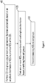
- FIGURE 4 depicts a flow diagram of a method in accordance with the invention.
- CSI is portioned into groups using at least one permutation function substantially based on an amplitude distribution to prioritize NZCs of the CSI.
- zero or more NZCs are omitted from said groups in accordance with said amplitude distribution based prioritizing.
- the remaining (that is, the NZCs not omitted) NZCs are transmitted in said groups.
- a priority permutation may also be applied to a bitmap of elements ⁇ l , m ⁇ , where each element of the bitmap indicates whether or not the corresponding coefficient c l , m ⁇ is considered to be non-zero or not.
- NZCs non-zero coefficients
- FIGURE 5 depicts a block diagram illustrating an example wireless apparatus (500) in accordance with embodiments of the invention.
- the wireless apparatus may include at least one processor (520), at least one memory (510) coupled to the at least one processor (520) and at least one suitable transceiver (530) having a transmitter and a receiver coupled to the at least one processor (520), coupled to at least one antenna unit (550) through at least one amplifier (540).
- the at least one memory (510) may store computer programs, which may, when executed by the at least one processor (520), for example in combination with any of the at least one transceiver (530), at least one amplifier (540) and at least one antenna unit (550), perform embodiments of the invention.
- a user equipment such as a mobile phone, car or drone, or a base station may be embodied in apparatus 500.
- Embodiments of the invention may be implemented in software (executed by one or more processors), hardware (e.g., an application specific integrated circuit or field programmable gate array), or a combination of software and hardware.
- the software e.g., application logic, an instruction set
- the software is maintained on any one of various conventional non-transitory computer-readable media.
Landscapes
- Engineering & Computer Science (AREA)
- Computer Networks & Wireless Communication (AREA)
- Signal Processing (AREA)
- Quality & Reliability (AREA)
- Mobile Radio Communication Systems (AREA)
Abstract
Description
- The present application relates generally to methods and apparatae for omission of feedback coefficients, for example to meet payload contraints.
- In radio communication systems, such as the New Radio currently being defined by 3GPP, feedback of uplink control information (UCI) such as channel state information (CSI) from user equipment (UE) to base station (BS) is used to allow the base station to control the connection between the two. UCI is generally transmitted on an uplink control channel, resources on which are allocated to the UE by the BS. In some instances, a UE may however have more UCI available for transmission than would fit in the allocated resources. A UE may in such cases wait for additional resources to transmit all available UCI, but this approach as drawbacks such as increasing the delay in transferring all UCI and forcing the BS to allocate resources for all UCI available at the UE. Better approaches are hence needed for UCI transfer.
- In 3GPP TS 38.214, a method was introduced omit a portions of CSI reports to ensure that the CSI payload would fit in an available resource allocation. This is achieved by dividing a variable part of a number (NRep ) of CSI reports configured to be carried in a CSI payload in a slot into 2NRep + 1 segments with different priority levels. Segments are then dropped in order of increasing priority until the UCI code rate falls below a threshold, such that the CSI payload fits in the available resource allocation.
- The priority levels are described in Table 5.2.3-1 of TS 38.214, reproduced below in Table 1, where
Priority 0 indicates highest priority and Priority 2NRep indicates lowest priority.Table 1: Priority reporting levels for Part 2 CSI.Priority 0: Part 2 wideband CSI for CSI reports 1 to NRepPriority 1: Part 2 subband CSI of even subbands for CSIreport 1Priority 2: Part 2 subband CSI of odd subbands for CSIreport 1Priority 3: Part 2 subband CSI of even subbands for CSIreport 2Priority 4: Part 2 subband CSI of odd subbands for CSIreport 2Priority 2NRep - 1: Part 2 subband CSI of even subbands for CSI report NRepPriority 2NRep : Part 2 subband CSI of odd subbands for CSI report NRep - As may be observed from Table 1, CSI is segmented in accordance with odd and even subbands. However, when frequency compression is introduced, such segmentation is no longer feasible. Accordingly, an alternative segmentation into groups has been agreed as depicted in Table 2. Certain parameters of each CSI report are carried in
group 0 with highest priority and other parameters of a CSI reports are split in two groups,group 1 andgroup 2.Table 2: Priority reporting levels for Part 2 CSI.Priority 0: Group 0 CSI for CSI reports 1 to N RepPriority 1: Group 1 CSI for CSIreport 1Priority 2: Group 2 CSI for CSIreport 1Priority 3: Group 1 CSI for CSIreport 2Priority 4: Part 2Group 2 CSI for CSIreport 2Priority 2N Rep - 1 : Group 1 CSI for CSI report NRepPriority 2N Rep : Group 2 CSI for CSI report N Rep - The coefficients of at least some the other parameters may then be restricted to its non-zero coefficients

- The nonzero coefficients are prioritized from high to low priority according to the index triplet (l,m,λ). The

group 1 and the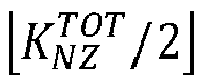
group 2. The priority level is assigns by the following function:
- Various aspects of examples of the invention are set out in the claims.
- According to a first aspect of the present invention, there is disclosed a method, apparatus and software program product for partitioning channel state information into groups of different priority levels, wherein said channel state information comprises non zero coefficients and said partitioning comprises using at least one permutation function to prioritize said non-zero coefficients substantially based on an amplitude distribution of said non zero coefficients to determine mapping of said non zero coefficients to said groups, and further for omitting zero or more non-zero coefficients in accordance with said amplitude distribution based prioritizing from said groups, and for transmitting remaining non zero coefficients in said groups.
- For a more complete understanding of example embodiments of the present invention, reference is now made to the following descriptions taken in connection with the accompanying drawings in which:
-
FIGURE 1 illustrates an embodiment of a partitioning of a CSI report into groups; -
FIGURE 2 illustrates an example depiction of a prioritization permutation in accordance with an amplitude distribution; and -
FIGURE 3 illustrates examples of application of a prioritization permutation sets of non-zero coefficients of different CSI reports accordance with an amplitude distribution; and -
FIGURE 4 illustrates a flow diagram in accordance with an embodiment of the invention; and -
FIGURE 5 illustrates an example wireless apparatus in accordance with embodiments of the invention. -
Figure 1 illustrates an embodiment of a portioning of a variable part of a CSI report into groups, wherein spatial domain rotation, spatial domain basis and strongest coefficient indicator parameters are assigned tohighest priority group 0, parameters FD-basis and reference amplitude are assigned to group one and certain non-zero coefficients (NZCs) of the variable part of the CSI report, for example a set of non-zero codebook linear combination coefficients of a precoding matrix indicator (PMI) representation, are split betweengroup group 1 orgroup 2 or may be split betweengroups - It is considered that when NCZs are assigned to
groups group 2 may be significantly larger than those ingroup 1, meaning that droppinggroup 2 would cause significant degradation in the PMI representation if the dropped coefficients are the most important ones, i.e., those with the largest amplitude. In another example, All NZCs of a layer might be assigned to a same group, where omitting that group would reduce the actual number of reported layers RI. Thus, in advantageous embodiments of the present invention, permutation functions π 1(m) and π 2(l) are provided that mitigate such undesirable effects. - In one embodiment, a priority permutation function is provided that is designed based on typical amplitude histograms of the NZC. Across the frequency division (FD) components, the amplitude of the NZC is significantly larger at the "edges" as compared to the "centre" of the frequency components. This is typical in a DFT transformation of a correlated (i.e., "low-pass") signal. Therefore, the priority permutation of FD components can be advantageously designed based on prioritizing components in order of typical decreasing average amplitude, by using the following mapping, where N 3 is the maximum index number reported in a FD basis indicator:

- This priority permutation π 1(m) can be expressed as:

- One skilled in the art will appreciate that a pair of FD components (m, N 3 - m) may be presumed to have similar amplitudes and thus may be reversed in priority order without departing from the scope the present invention.
- If the selected FD basis consists of M < N 3 components and the index m is defined in the set: {0,1, ..., M - 1}, the 'local' index m in the right-hand side of equations (3) may be replaced by the 'global' index corresponding to the m-th selected FD component in the set: {0,1, ... N 3 - 1}. If km is such index, then the function (3) becomes

-
Figure 2 provides an example depiction of the priority permutation for a case where N 3 equals 8. In another embodiment, a priority permutation function is provided based on typical amplitude histograms of spatial domain (SD) beams, where it may be observed that across SD beams, the histogram of amplitudes of the NZC shows a symmetry between the two polarizations, such that the average amplitude of a beam l in the horizontal polarization is similar to that of beam l + L in the vertical polarization. Therefore, the priority permutation of the SD beams can be designed to enumerate the SD beam in order of decreasing average amplitude by using the following mapping where l* indicates the SD beam of the strongest coefficient as indicated by the strongest coefficient indicator (SCI).
- The priority permutation π 2(l) be expressed as:

- In some embodiments π 1(m) may be set in accordance with Eq. 3, Eq. 4 or an equivalent function in combination with π 2(l) set in accordance with Eq. 6 or an equivalent function, whereas in other embodiments, π 1(m) may be set in accordance with Eq. 3, Eq. 4 or an equivalent function whereas π 2(l) may be set to 1 (i.e. no layer permutation) or a different permutation function than provided in Eq. 6. In yet other embodiments, π 2(l) may be set in accordance with Eq. 6 or an equivalent function whereas π 1(m) may be set to 1 or a different permutation function than provided in Eq. 3 or Eq. 4.
- After priorities have been assigned to the NZCs in accordance with priority permutations of at least one Eq. 3, Eq. 4, Eq. 6 or Eq. 6 or equivalent permutations, CSI groups may be omitted in order of increasing priority until the UCI code rate falls below a threshold, such that the CSI payload fits in the available resource allocation.
- In certain embodiments, priorities for NZCs are allocated for a frequency domain basis on the basis of a typical amplitude order of a signal, for example a DFT of a correlated signal. In certain embodiments, priorities for NZCs are allocated for a frequency domain basis on the basis of prioritizing coefficients from the edges of the frequency domain inwards until the center coefficient(s) of the frequency domain forms/form the lowest priority coefficient(s). It is noted that no actual measument of (e.g. instantaneous) amplitudes is foreseen to affect the ordering, as such ordering would require providing information about the ordering in the CSI payload (or through alternative signaling) as well. Thus, the priorities are set substantially in accordance with the amplitudes of the non-zero coefficients, though may not be set exactly in accordance with the amplitudes of the NZCs of an individual CSI report as the amplitudes of the NZCs of an individual CSI report may fluctuate relative to the typical amplitude histogram for the NZCs.
-
FIGURE 3 depicts an example of the priority permutation of the NZCs of two individual CSI reports. For an individual CSI report depicted under (a), it may be seen that the amplitudes of the NZCs, depicted by arrows, are not indentical to the typical amplitude histogram, but that their amplitudes relative to each other follow the typical amplitude histogram, such that application of the priority permutation results in the NZCs to be ordered by their relative amplitude. For an individual CSI report depicted under (b), it may be seen that the amplitudes of the NZCs, depicted by arrows, are not indentical to the typical amplitude histogram, and that the amplitudes ofNZCs NZCs - Omission of lowest priority NZCs in correspondence with (a) of
Figure 3 hence causes the lowest amplitude NCZs to be omitted as desired, wheras omission of lowest priority NZCs in correspondence with (a) ofFigure 3 may cause highest amplitudes NCZs 1 and 6 to be omitted whileNZCs -
FIGURE 4 depicts a flow diagram of a method in accordance with the invention. At 410, CSI is portioned into groups using at least one permutation function substantially based on an amplitude distribution to prioritize NZCs of the CSI. At 420, zero or more NZCs are omitted from said groups in accordance with said amplitude distribution based prioritizing. At 430, the remaining (that is, the NZCs not omitted) NZCs are transmitted in said groups. - It may be understood that rather than applying any of the disclosed priority permutations on the NZCs or in addition to applying any of the disclosed priority permutations, a priority permutation may also be applied to a bitmap of elements


-
FIGURE 5 depicts a block diagram illustrating an example wireless apparatus (500) in accordance with embodiments of the invention. The wireless apparatus may include at least one processor (520), at least one memory (510) coupled to the at least one processor (520) and at least one suitable transceiver (530) having a transmitter and a receiver coupled to the at least one processor (520), coupled to at least one antenna unit (550) through at least one amplifier (540). The at least one memory (510) may store computer programs, which may, when executed by the at least one processor (520), for example in combination with any of the at least one transceiver (530), at least one amplifier (540) and at least one antenna unit (550), perform embodiments of the invention. For example, a user equipment, such as a mobile phone, car or drone, or a base station may be embodied inapparatus 500. - Embodiments of the invention may be implemented in software (executed by one or more processors), hardware (e.g., an application specific integrated circuit or field programmable gate array), or a combination of software and hardware. In an example embodiment, the software (e.g., application logic, an instruction set) is maintained on any one of various conventional non-transitory computer-readable media.
- Although various aspects are set out above, other aspects comprise other combinations of features from the described embodiments, and not solely the combinations described above.
Claims (15)
- A method, comprising:partitioning channel state information into groups of different priority levels, wherein said channel state information comprises non-zero coefficients;said partitioning comprising using at least one priority permutation to prioritize said non-zero coefficients substantially based on an amplitude distribution of said non-zero coefficients to determine mapping of said non-zero coefficients to said groups;omitting zero or more non-zero coefficients in accordance with said amplitude distribution based prioritizing from said groups; andtransmitting remaining non-zero coefficients in said groups.
- The method of claim 1, wherein said at least one priority permutation maps a non-zero coefficient at index m according to the following order of the corresponding frequency domain component km and comprises at least:

- The method of claim 1, wherein said at least one priority permutation maps a non-zero coefficient at index m at least according to:

- The method of claim 1, wherein said at least one priority permutation maps a non-zero coefficient at index l at least according to:

- The method of claim 1, wherein said at least one priority permutation prioritizes non-zero coefficients from edges of a frequency domain, at which the non-zero coefficients are designated as highest priority coefficients, inwards until center coefficient(s) of the frequency domain is/are designated as lowest priority coefficient(s).
- The method of claim 1, wherein using said at least one priority permutation to prioritize said non-zero coefficients substantially based on an amplitude distribution does not comprise measurement of amplitudes of said non-zero coefficients.
- The method of any of claims 1-6, where said priorization of non-zero coefficents


- An apparatus, comprising:means for partitioning channel state information into groups of different priority levels, wherein said channel state information comprises non-zero coefficients;said partition comprising use of at least one priority permutation to prioritize said non-zero coefficients substantially based on an amplitude distribution of said non-zero coefficients to determine mapping of said non-zero coefficients to said groups;means for omitting zero or more non-zero coefficients in accordance with said amplitude distribution based prioritizing from said groups; andmeans for transmitting remaining non-zero coefficients in said groups.
- The apparatus of claim 8, wherein said at least one priority permutation maps a non-zero coefficient at index m according to the following order of the corresponding frequency domain component km and comprises at least:

- The apparatus of claim 8, wherein said at least one priority permutation maps a non-zero coefficient at index m at least according to:

- The apparatus of claim 8, wherein said at least one priority permutation maps a non-zero coefficient at index l at least according to:

- The apparatus of claim 8, wherein said at least one priority permutation prioritizes non-zero coefficients from edges of a frequency domain, at which the non-zero coefficients are designated as highest priority coefficients, inwards until center coefficient(s) of the frequency domain is/are designated as lowest priority coefficient(s).
- The apparatus of claim 8, wherein using said at least one priority permutation to prioritize said non-zero coefficients substantially based on an amplitude distribution does not comprise measurement of amplitudes of said non-zero coefficients.
- The apparatus of any of claim 8-13, where said priorization of non-zero coefficents


- A method, comprising:partitioning channel state information into groups of different priority levels, wherein said channel state information comprising a bitmap indicating whether corresponding coefficients are zero value co-efficients or non-zero coefficients;said partitioning comprising using at least one priority permutation to prioritize said bitmap substantially based on an amplitude distribution of said non-zero coefficients to determine mapping of elements of said bitmap to said groups;omitting zero or more bitmap elements in accordance with said amplitude distribution based prioritizing from said groups; andtransmitting remaining bitmap elements in said groups.
Applications Claiming Priority (1)
| Application Number | Priority Date | Filing Date | Title |
|---|---|---|---|
| FI20195893A FI129704B (en) | 2019-10-16 | 2019-10-16 | Method and apparatus for feedback coefficient omission |
Publications (1)
| Publication Number | Publication Date |
|---|---|
| EP3809618A1 true EP3809618A1 (en) | 2021-04-21 |
Family
ID=72752313
Family Applications (1)
| Application Number | Title | Priority Date | Filing Date |
|---|---|---|---|
| EP20200031.1A Pending EP3809618A1 (en) | 2019-10-16 | 2020-10-05 | Method and apparatus for feedback coefficient omission |
Country Status (5)
| Country | Link |
|---|---|
| US (1) | US11476913B2 (en) |
| EP (1) | EP3809618A1 (en) |
| CN (1) | CN112671441B (en) |
| FI (1) | FI129704B (en) |
| WO (1) | WO2021074486A1 (en) |
Families Citing this family (5)
| Publication number | Priority date | Publication date | Assignee | Title |
|---|---|---|---|---|
| CN113486550B (en) * | 2021-06-23 | 2023-07-14 | 北京科技大学 | A method for determining triplet feed coefficients in hardware-in-the-loop radio frequency simulation |
| WO2023277482A1 (en) * | 2021-07-01 | 2023-01-05 | 엘지전자 주식회사 | Method and device for transmitting and receiving channel state information on basis of codebook in wireless communication system |
| CN117792444A (en) * | 2022-09-21 | 2024-03-29 | 维沃移动通信有限公司 | PMI combination coefficient sending method, device and terminal |
| CN117998384A (en) * | 2022-10-28 | 2024-05-07 | 华为技术有限公司 | Communication method and communication device |
| CN118301747A (en) * | 2023-01-04 | 2024-07-05 | 维沃移动通信有限公司 | Feedback method, device, terminal and storage medium of PMI combination coefficient |
Family Cites Families (8)
| Publication number | Priority date | Publication date | Assignee | Title |
|---|---|---|---|---|
| ES2901556T3 (en) * | 2006-09-26 | 2022-03-22 | Optis Wireless Technology Llc | Communications scheme for channel quality information |
| WO2017161590A1 (en) * | 2016-03-25 | 2017-09-28 | Qualcomm Incorporated | Enhanced hybrid csi-rs for fd-mimo |
| CN109417415B (en) * | 2016-07-11 | 2022-06-07 | 苹果公司 | System and method for confirming beam switching |
| WO2018056877A1 (en) * | 2016-09-23 | 2018-03-29 | Telefonaktiebolaget Lm Ericsson (Publ) | Method and apparatus for providing channel state information status by a transceiver |
| US10742290B2 (en) * | 2017-04-13 | 2020-08-11 | Samsung Electronics Co., Ltd. | High-resolution CSI reporting based on unequal bit allocation in advanced wireless communication systems |
| US10868603B2 (en) * | 2018-03-09 | 2020-12-15 | Samsung Electronics Co., Ltd. | Method and apparatus to enable CSI reporting based on space-frequency compression |
| US11463142B2 (en) * | 2019-09-06 | 2022-10-04 | Samsung Electronics Co., Ltd. | Method and apparatus for uplink control information omission |
| US11743802B2 (en) * | 2020-10-07 | 2023-08-29 | Qualcomm Incorporated | Timing management for wireless remote units |
-
2019
- 2019-10-16 FI FI20195893A patent/FI129704B/en active IP Right Grant
-
2020
- 2020-10-05 EP EP20200031.1A patent/EP3809618A1/en active Pending
- 2020-10-05 WO PCT/FI2020/050654 patent/WO2021074486A1/en not_active Ceased
- 2020-10-07 US US17/065,175 patent/US11476913B2/en active Active
- 2020-10-16 CN CN202011107229.7A patent/CN112671441B/en active Active
Non-Patent Citations (1)
| Title |
|---|
| MOTOROLA MOBILITY ET AL: "Type II MU-CSI Enhancement", vol. RAN WG1, no. Chongqing, China; 20191014 - 20191020, 5 October 2019 (2019-10-05), XP051808800, Retrieved from the Internet <URL:https://ftp.3gpp.org/tsg_ran/WG1_RL1/TSGR1_98b/Docs/R1-1911033.zip> [retrieved on 20191005] * |
Also Published As
| Publication number | Publication date |
|---|---|
| US11476913B2 (en) | 2022-10-18 |
| CN112671441A (en) | 2021-04-16 |
| FI129704B (en) | 2022-07-15 |
| FI20195893A1 (en) | 2021-04-17 |
| WO2021074486A1 (en) | 2021-04-22 |
| US20210119684A1 (en) | 2021-04-22 |
| CN112671441B (en) | 2024-08-23 |
Similar Documents
| Publication | Publication Date | Title |
|---|---|---|
| EP3809618A1 (en) | Method and apparatus for feedback coefficient omission | |
| JP7631310B2 (en) | CSI reporting based on ternary codebooks | |
| EP3780819B1 (en) | Scheduling subband allocation method and apparatus | |
| JP2022515220A (en) | Methods and equipment for feedback reporting in wireless communication networks | |
| CN109510654B (en) | Method and device for channel state information feedback | |
| CN113055138B (en) | A kind of instruction message transmission method and communication device | |
| JP2020521381A (en) | Uplink precoding method, apparatus and system | |
| US12418334B2 (en) | Codebook feedback method, network device, terminal device, and computer storage medium | |
| EP4092922B1 (en) | Precoding information | |
| EP3764708A1 (en) | Method for transmitting data on bandwidth part, terminal device, and network device | |
| KR20230043710A (en) | Control signaling for uplink frequency selective precoding | |
| US20220303076A1 (en) | Method, device and computer readable medium for channel state information transmission | |
| CN112187324A (en) | Channel state information feedback method and device | |
| EP4465686A1 (en) | Information reporting method and apparatus, information receiving method and apparatus, device, and storage medium | |
| US12262384B2 (en) | Apparatus, method and computer program for uplink control signalling | |
| US12267137B2 (en) | Reporting channel state information (CSI) precoding matrix indicator (PMI) | |
| US20240171246A1 (en) | Channel state information transmission method and apparatus, terminal, base station, and storage medium | |
| EP3136802B1 (en) | Pilot configuration method and apparatus | |
| CN114557014A (en) | Information reporting method, information receiving method, device, equipment and storage medium | |
| EP4622336A1 (en) | Data set sending and receiving methods, electronic device, and storage medium | |
| EP4611298A1 (en) | Indication information sending method and apparatus, indication information receiving method and apparatus, and storage medium | |
| EP4668943A1 (en) | Method for reporting time domain channel property (tdcp), apparatus, and storage medium | |
| HK40043636B (en) | Methods and apparatuses for codebook restriction for type-ii feedback reporting and higher layer configuration and reporting for linear combination codebook in a wireless communications network |
Legal Events
| Date | Code | Title | Description |
|---|---|---|---|
| PUAI | Public reference made under article 153(3) epc to a published international application that has entered the european phase |
Free format text: ORIGINAL CODE: 0009012 |
|
| STAA | Information on the status of an ep patent application or granted ep patent |
Free format text: STATUS: THE APPLICATION HAS BEEN PUBLISHED |
|
| AK | Designated contracting states |
Kind code of ref document: A1 Designated state(s): AL AT BE BG CH CY CZ DE DK EE ES FI FR GB GR HR HU IE IS IT LI LT LU LV MC MK MT NL NO PL PT RO RS SE SI SK SM TR |
|
| AX | Request for extension of the european patent |
Extension state: BA ME |
|
| STAA | Information on the status of an ep patent application or granted ep patent |
Free format text: STATUS: REQUEST FOR EXAMINATION WAS MADE |
|
| 17P | Request for examination filed |
Effective date: 20211021 |
|
| RBV | Designated contracting states (corrected) |
Designated state(s): AL AT BE BG CH CY CZ DE DK EE ES FI FR GB GR HR HU IE IS IT LI LT LU LV MC MK MT NL NO PL PT RO RS SE SI SK SM TR |
|
| STAA | Information on the status of an ep patent application or granted ep patent |
Free format text: STATUS: EXAMINATION IS IN PROGRESS |
|
| 17Q | First examination report despatched |
Effective date: 20221215 |