EP3809567A1 - Assembly of a multi-segment stator - Google Patents
Assembly of a multi-segment stator Download PDFInfo
- Publication number
- EP3809567A1 EP3809567A1 EP19203583.0A EP19203583A EP3809567A1 EP 3809567 A1 EP3809567 A1 EP 3809567A1 EP 19203583 A EP19203583 A EP 19203583A EP 3809567 A1 EP3809567 A1 EP 3809567A1
- Authority
- EP
- European Patent Office
- Prior art keywords
- stator
- reference objects
- segment
- shaft
- plural
- Prior art date
- Legal status (The legal status is an assumption and is not a legal conclusion. Google has not performed a legal analysis and makes no representation as to the accuracy of the status listed.)
- Withdrawn
Links
- 238000000034 method Methods 0.000 claims abstract description 59
- 238000005259 measurement Methods 0.000 claims description 26
- 239000000853 adhesive Substances 0.000 claims description 3
- 230000001070 adhesive effect Effects 0.000 claims description 3
- 230000008569 process Effects 0.000 description 10
- 238000001514 detection method Methods 0.000 description 3
- 238000004519 manufacturing process Methods 0.000 description 3
- 239000003302 ferromagnetic material Substances 0.000 description 2
- 230000006870 function Effects 0.000 description 2
- 230000005291 magnetic effect Effects 0.000 description 2
- OKTJSMMVPCPJKN-UHFFFAOYSA-N Carbon Chemical compound [C] OKTJSMMVPCPJKN-UHFFFAOYSA-N 0.000 description 1
- 229910052799 carbon Inorganic materials 0.000 description 1
- 230000008859 change Effects 0.000 description 1
- 238000010276 construction Methods 0.000 description 1
- 238000007796 conventional method Methods 0.000 description 1
- 230000001419 dependent effect Effects 0.000 description 1
- 230000005670 electromagnetic radiation Effects 0.000 description 1
- 238000003384 imaging method Methods 0.000 description 1
- 238000010801 machine learning Methods 0.000 description 1
- 238000012544 monitoring process Methods 0.000 description 1
- NJPPVKZQTLUDBO-UHFFFAOYSA-N novaluron Chemical compound C1=C(Cl)C(OC(F)(F)C(OC(F)(F)F)F)=CC=C1NC(=O)NC(=O)C1=C(F)C=CC=C1F NJPPVKZQTLUDBO-UHFFFAOYSA-N 0.000 description 1
- 230000035699 permeability Effects 0.000 description 1
- 230000008707 rearrangement Effects 0.000 description 1
- 125000006850 spacer group Chemical group 0.000 description 1
- 230000003595 spectral effect Effects 0.000 description 1
- 238000013519 translation Methods 0.000 description 1
- 238000004804 winding Methods 0.000 description 1
Images


Classifications
-
- H—ELECTRICITY
- H02—GENERATION; CONVERSION OR DISTRIBUTION OF ELECTRIC POWER
- H02K—DYNAMO-ELECTRIC MACHINES
- H02K41/00—Propulsion systems in which a rigid body is moved along a path due to dynamo-electric interaction between the body and a magnetic field travelling along the path
- H02K41/02—Linear motors; Sectional motors
- H02K41/03—Synchronous motors; Motors moving step by step; Reluctance motors
- H02K41/031—Synchronous motors; Motors moving step by step; Reluctance motors of the permanent magnet type
-
- H—ELECTRICITY
- H02—GENERATION; CONVERSION OR DISTRIBUTION OF ELECTRIC POWER
- H02K—DYNAMO-ELECTRIC MACHINES
- H02K15/00—Processes or apparatus specially adapted for manufacturing, assembling, maintaining or repairing of dynamo-electric machines
- H02K15/50—Disassembling, repairing or modifying dynamo-electric machines
-
- H—ELECTRICITY
- H02—GENERATION; CONVERSION OR DISTRIBUTION OF ELECTRIC POWER
- H02K—DYNAMO-ELECTRIC MACHINES
- H02K15/00—Processes or apparatus specially adapted for manufacturing, assembling, maintaining or repairing of dynamo-electric machines
- H02K15/02—Processes or apparatus specially adapted for manufacturing, assembling, maintaining or repairing of dynamo-electric machines of stator or rotor bodies
-
- G—PHYSICS
- G01—MEASURING; TESTING
- G01B—MEASURING LENGTH, THICKNESS OR SIMILAR LINEAR DIMENSIONS; MEASURING ANGLES; MEASURING AREAS; MEASURING IRREGULARITIES OF SURFACES OR CONTOURS
- G01B11/00—Measuring arrangements characterised by the use of optical techniques
- G01B11/002—Measuring arrangements characterised by the use of optical techniques for measuring two or more coordinates
-
- G—PHYSICS
- G01—MEASURING; TESTING
- G01B—MEASURING LENGTH, THICKNESS OR SIMILAR LINEAR DIMENSIONS; MEASURING ANGLES; MEASURING AREAS; MEASURING IRREGULARITIES OF SURFACES OR CONTOURS
- G01B11/00—Measuring arrangements characterised by the use of optical techniques
- G01B11/02—Measuring arrangements characterised by the use of optical techniques for measuring length, width or thickness
- G01B11/026—Measuring arrangements characterised by the use of optical techniques for measuring length, width or thickness by measuring distance between sensor and object
-
- G—PHYSICS
- G01—MEASURING; TESTING
- G01B—MEASURING LENGTH, THICKNESS OR SIMILAR LINEAR DIMENSIONS; MEASURING ANGLES; MEASURING AREAS; MEASURING IRREGULARITIES OF SURFACES OR CONTOURS
- G01B11/00—Measuring arrangements characterised by the use of optical techniques
- G01B11/26—Measuring arrangements characterised by the use of optical techniques for measuring angles or tapers; for testing the alignment of axes
-
- G—PHYSICS
- G01—MEASURING; TESTING
- G01C—MEASURING DISTANCES, LEVELS OR BEARINGS; SURVEYING; NAVIGATION; GYROSCOPIC INSTRUMENTS; PHOTOGRAMMETRY OR VIDEOGRAMMETRY
- G01C11/00—Photogrammetry or videogrammetry, e.g. stereogrammetry; Photographic surveying
- G01C11/02—Picture taking arrangements specially adapted for photogrammetry or photographic surveying, e.g. controlling overlapping of pictures
-
- H—ELECTRICITY
- H02—GENERATION; CONVERSION OR DISTRIBUTION OF ELECTRIC POWER
- H02K—DYNAMO-ELECTRIC MACHINES
- H02K1/00—Details of the magnetic circuit
- H02K1/06—Details of the magnetic circuit characterised by the shape, form or construction
- H02K1/12—Stationary parts of the magnetic circuit
- H02K1/14—Stator cores with salient poles
- H02K1/146—Stator cores with salient poles consisting of a generally annular yoke with salient poles
- H02K1/148—Sectional cores
-
- H—ELECTRICITY
- H02—GENERATION; CONVERSION OR DISTRIBUTION OF ELECTRIC POWER
- H02K—DYNAMO-ELECTRIC MACHINES
- H02K21/00—Synchronous motors having permanent magnets; Synchronous generators having permanent magnets
- H02K21/12—Synchronous motors having permanent magnets; Synchronous generators having permanent magnets with stationary armatures and rotating magnets
- H02K21/22—Synchronous motors having permanent magnets; Synchronous generators having permanent magnets with stationary armatures and rotating magnets with magnets rotating around the armatures, e.g. flywheel magnetos
-
- H—ELECTRICITY
- H02—GENERATION; CONVERSION OR DISTRIBUTION OF ELECTRIC POWER
- H02K—DYNAMO-ELECTRIC MACHINES
- H02K2201/00—Specific aspects not provided for in the other groups of this subclass relating to the magnetic circuits
- H02K2201/15—Sectional machines
-
- H—ELECTRICITY
- H02—GENERATION; CONVERSION OR DISTRIBUTION OF ELECTRIC POWER
- H02K—DYNAMO-ELECTRIC MACHINES
- H02K7/00—Arrangements for handling mechanical energy structurally associated with dynamo-electric machines, e.g. structural association with mechanical driving motors or auxiliary dynamo-electric machines
- H02K7/18—Structural association of electric generators with mechanical driving motors, e.g. with turbines
- H02K7/1807—Rotary generators
- H02K7/1823—Rotary generators structurally associated with turbines or similar engines
- H02K7/183—Rotary generators structurally associated with turbines or similar engines wherein the turbine is a wind turbine
Definitions
- the present invention relates to a method and to an arrangement of determining a readjustment value in position and/or orientation of a stator segment of a multi-segment stator of an electrical machine. Further, the present invention relates to a method of assembling a stator segment of such a multi-segment stator with a shaft and further relates to a method of assembling a multi-segment stator of an electrical machine.
- an electrical machine such as a generator or a motor
- the stator is conventionally assembled from multiple stator segments.
- the multiple stator segments need to be properly assembled. Assembling the multiple stator segment requires to properly adjust or align or arrange those stator segments regarding position and/or orientation.
- a method of determining a readjustment value in position and/or in orientation of a stator segment of a multi segment stator of an electrical machine, the stator segment to be assembled with a shaft comprising: detecting positions of plural first reference objects attached to the stator segment using a camera system; detecting positions of plural second reference objects attached to the shaft using a laser tracking system; detecting positions of plural third reference objects attached to the camera system using the laser tracking system; determining the readjustment value in position and/or in orientation of the stator segment based on the positions of the plural first, second and third reference objects.
- the method may be performed by an arrangement for determining a readjustment value according to an embodiment of the present invention.
- the method may partly be implemented in software and/or hardware.
- the readjustment value may relate to a value regarding position and/or a value regarding orientation of the stator segment.
- the readjustment value may for example be given in a length unit and/or angle unit, such as degrees.
- the multi segment stator may essentially have a cylindrical shape.
- the electrical machine may be an electrical generator or an electrical motor. In particular, the electrical machine may be an electrical generator of a wind turbine.
- the stator segment may comprise ferromagnetic material, in particular soft ferromagnetic material, having a high permeability.
- the completed stator may further comprise one or multiple (for example three-phase) winding sets which are wound around teeth or through slots comprised in each of the stator segments.
- the shaft may also have a cylindrical shape and may comprise a center axis, in particular symmetry axis. Each stator segment is to be assembled with a shaft and then, after successful positioning, has to be mounted thereon.
- the first reference objects and also the second reference objects and also the third reference objects may be objects which are easily visible by imaging those using one or more cameras of the camera system.
- the reference objects may be active reference objects such as light sources or may be inactive reference objects, such as particular reflectors, such as cateye reflectors.
- the reference objects may have a relatively small (lateral) extension or size, such as for example between 0.5 mm and 10 mm and may have even smaller thickness such as between 0.01 mm and 1 mm. All reference objects may be attached to the respective stator segment or shaft or camera system at predetermined positions. By detecting the position of the reference objects, the position and orientation of the entire object to which they are respectively attached, i.e. the stator segment, the shaft and the camera system, may be derivable and derived by the method.
- the first reference objects may all be attached to a radial outer surface of the respective stator segment, in particular including also a first reference object at each corner (or edge) of the stator segment.
- the second reference objects may be attached at a radial outer surface of the shaft, in particular including at least some second reference objects which are arranged in a same plane perpendicular to the axis of the shaft.
- the third reference objects may be attached to (a frame or casing of or one or more cameras of) the camera system also at predetermined positions.
- the laser tracking system may comprise a laser source for generating a laser beam, a goniometer for directing the laser beam in a particular direction and for measuring direction angles, in particular two angles (for example of a spherical coordinate system).
- the laser tracking system may further comprise a distance measurement capability using the laser beam and an interferometer e.g. Thereby, the laser tracking system is enabled to determine a three-dimensional position of each of the third reference objects and each of the second reference objects.
- the camera system does not need to acquire image data from the shaft. Position and/or orientation of the shaft may only be detected using the laser tracking system.
- the laser tracking system also detects the positions of the plural third reference objects attached to the camera system, a positional and orientational relationship between the position and orientation of the camera system and the position and orientation of the shaft can be established.
- a relative arrangement of the stator segment relative to the shaft can be established or derived by the method. Thereby, it may be determined whether the stator segment is positioned and oriented in a desired or target position and orientation, in particular relative to the shaft.
- the readjustment value i.e. a value according to which the stator segment is to be rearranged (to result in the target position and/or orientation), may easily be determined.
- the accuracy may be improved, since the laser tracking system is enabled with high accuracy to determine position of an object relatively far away, while the camera system may provide positional data with lower and lower accuracy for farer and farer apart objects.
- the position of the shaft would not have been determined in such high accuracy compared to using the laser tracking system.
- the method further comprises determining position and orientation of an axis of the shaft based on the positions of the plural second reference objects, wherein determining the readjustment value is further based on the determined position and orientation of the axis of the shaft.
- the axis of the shaft may be a cylinder symmetry axis of the shaft.
- the axis of the shaft may further coincide with the axis of a rotor of the electrical machine, in particular outer rotor, having for example permanent magnets attached.
- the second reference objects may be arranged for example in equal distances in a circumferential direction around an outer surface of the shaft, in particular in one or several planes perpendicular to the axis of the shaft.
- the arithmetic mean of the (e.g. 3D) positions of all the second reference objects may define the location of the axis of the shaft in this plane.
- the axis may then be inferred to be perpendicular to this plane.
- measuring second reference objects in several (axially spaced apart) planes may enable to also derive the direction of the axis.
- the outer surface (or any other point) of the stator segment may for example be intended to be arranged at a particular distance from the axis of the shaft. Thus, knowing the position and/or orientation of the axis may easily allow to determine the readjustment value.
- the camera system comprises at least two or three or four cameras or more cameras each acquiring 2D image data from the stator segment from different viewing areas, wherein detecting the positions of the plural first reference objects comprises 3D reconstruction of a volume portion comprising the first reference objects based on the 2D image data of each of the at least two cameras.
- the one or more cameras may be visible light sensitive cameras each including e.g. a two-dimensional array of light sensitive elements.
- the cameras may be sensitive to different spectral ranges of the electromagnetic radiation, such as infrared, visible, ultraviolet and a combination therefrom.
- the two or more cameras may be arranged at different positions and may be arranged in different or same orientations.
- the stator segment may be viewed by the different cameras from different viewing directions and/or positions.
- the first reference objects may for example be imaged as relatively bright features in the images.
- the images or the reconstructed 3D volume may be searched for the first reference objects by any peak detection method e.g.
- the 3D reconstruction may for example comprise a back projection using the two-dimensional images of the different cameras or may also involve Fourier techniques.
- the position of the camera system (in particular each of the cameras comprised in the camera system) is known from the detection of the positions of the third reference objects using the laser tracking system, which also determines the positions of the second reference objects on the shaft, the positional relationship between the shaft and the stator segment can be established.
- the plural first reference objects include at least 9, in particular between 9 and 100, or more first reference objects, which are in particular attached to a radial outer surface of the stator segment, and/or wherein the plural second reference objects include at least 3, in particular between 3 and 6, or more, second reference objects, from which at least 3 are arranged in a same plane perpendicular to the axis of the shaft, and/or wherein the plural third reference objects include, in particular for each camera of the camera system, at least 4, or more, third reference objects, wherein the first and/or second and/or third reference objects in particular include light reflectors attached using adhesive.
- the first reference objects may for example include in each (of one or plural) plane perpendicular to a cylinder axis of the respective stator element three first reference objects or more than three objects, such as four, five, six or even more.
- the first reference objects may be arranged in three axially spaced apart planes each plane having three first reference objects.
- all first reference objects may be visible and imaged by all cameras of the camera system.
- the second reference objects may be arranged around an outer circumference of the shaft, for example at same angular distances from each other. Detection of three such second reference objects already would be sufficient in order to determine the position and the orientation of the axis of the shaft, if a cylindrical symmetry of the shaft and the placement of the second reference objects is assumed.
- the camera system may comprise one or more cameras in fixed relative position and orientation. In this case, it may be sufficient to apply for example four third reference objects for example arranged at four corners of the camera system.
- the viewing angle of all the cameras comprised in the camera system may then be derived from the predetermined relative position of all the cameras within the camera system (and pre-known orientation of the cameras within the camera system) and the positions of the at least four third reference objects.
- the laser tracking system is configured to detect the positions of the plural second and the third reference objects by detecting two angle values and a distance value of each of the second and the third reference objects.
- the laser tracking system may comprise a goniometer for measuring a direction of a laser beam emitted by the laser tracking system.
- the goniometer thereby allows the determination of the two angles, such as spherical angles. Having further the distance value (towards the detected reference object) determined by the laser tracking system thus allows the determination of the three-dimensional coordinate of the respective detected reference objects.
- the camera system and/or the laser tracking system is configured to acquire measurement data at a rate of between 1 Hz and 10 Hz or more.
- the assembly process may be accelerated.
- the assembly process may resemble a live process where immediately after a slight rearrangement the measurement result is available.
- determining the readjustment value in position and/or in orientation of the stator segment is further based: on a target geometry of the stator, and/or on a target position and orientation of the stator segment relative to the shaft.
- the target geometry may relate to a geometry of an outer surface of the completed stator.
- the target position and orientation of the stator segment may for example comprise the definition of the distance between the axis of the shaft and the outer surface of the respective stator segment.
- the target geometry of the stator segment and/or on a target position and orientation of the stator segment relative to the shaft is derived from geometry data of a rotor, in particular outer rotor, of the electrical machine, the rotor to be assembled with the completed stator.
- the rotor ideally may have at for example a radially inner surface a (at least substantially) cylindrical shape. Due to manufacturing tolerances or errors however, the radially inner surface of the rotor may not exactly correspond to a cylinder.
- the rotor may in particular have different radii at different circumferential (and/or axial) positions.
- the target geometry of the stator may be defined such as to have a maximal diameter which is smaller (for example by the drive air gap) than the minimal radially inner diameter of the rotor.
- the stator may be assembled in a shape which is individually defined for a particular rotor. Thereby, the method may be applied to differently shaped rotors.
- the geometry data of the rotor in particular comprise at least data indicative of or defining a minimal diameter of the rotor.
- the 3D coordinates of the respective reference objects may easily be determined using for example reconstructed two-dimensional image data or using the laser tracking data. Internally, the method may work not only with the respective 3D coordinates of all the reference objects but may also include geometry or shape data of the respective stator segment, and/or the shaft and/or the rotor.
- the stator segment is shaped as a cylinder segment, spanning between 20° and 180°; and/or wherein the shaft has a cylindrical shape.
- the stator may for example be assembled by two, three, four, five, six or even more separate stator segments. Thereby, also relatively large electrical machines and respective stators may be assembled and built by applying the method.
- the shaft may be different from a cylindrical shape, for example having a quadratic, rectangular or oval shape in cross-section.
- a method of assembling a stator segment of a multi segment stator of an electrical machine with a shaft comprising: performing a method of determining a readjustment value in position and/or in orientation of a stator segment of the multi segment stator according to one of the preceding embodiments; changing position and/or orientation of the stator segment according to the readjustment value; and mounting the stator segment to the shaft, if the readjustment value in position and/or in orientation is below a threshold.
- the changing the position and the orientation may be performed manually e.g. by applying inserting appropriate spacer elements or distance changing elements.
- the changing the position and the orientation may be performed using a hydraulic and/or electrical motor manipulator system holding the stator segment and being enabled to move the stator segment by predefined or desired length extensions and turn the stator segment around desired axes having a desired angle.
- the method of determining the readjustment value and the changing the position and/or orientation of the stator segment may be performed in an iterative manner until the readjustment value is below a threshold or until the reached position and/or orientation of the stator segment equals to a target position and/or orientation or deviates from this target position and/or orientation only by tolerable amount.
- a method of assembling a multi segment stator of an electrical machine comprising: performing a method of assembling a stator segment of the multi segment stator with a shaft according to the preceding embodiment for all stator segments, wherein in particular the laser tracking system and/or the camera system is fixed; and assembling the multi segment stator with a rotor, in particular an outer rotor, in particular including plural mounted permanent magnets.
- the system of already assembled stator segments with the shaft may be rotated to bring the next stator segment to be assembled into the viewing range of the tracking system and the camera system.
- the emerging stator including the already assembled stator segments with the shaft may be held fixed and the camera system as well as the laser tracking system may be rotated or moved to a next position where a next stator segment is to be assembled.
- an arrangement for determining a readjustment value in position and/or in orientation of a stator segment of a multi segment stator of an electrical machine, the stator segment to be assembled with a shaft comprising: a camera system configured to detect positions of plural first reference objects attached to the stator segment; a laser tracking system configured: to detect positions of plural second reference objects attached to the shaft; to detect positions of plural third reference objects attached to the camera system; and a processor configured to determine the readjustment value in position and/or in orientation of the stator segment based on the positions of the plural first, second and third reference objects.
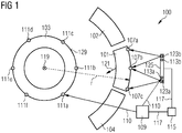
- the arrangement 100 for determining a readjustment value in position and/or in orientation of a stator segment 101 of an electrical machine comprises a camera system 105 which is configured to detect positions of plural first reference objects 107a, 107b, 107c attached to the stator segment 101.
- the arrangement 100 further comprises a laser tracking system 109 which is configured to detect positions of plural second reference objects 111a, ..., 111f attached to the shaft 103.
- the laser tracking system 109 is further configured to detect positions of plural third reference objects 113a, 113b attached to the camera system 105. Thereby a laser beam 110 is generated and emitted in a particular direction involving distance and angle measurement.
- the arrangement 100 further comprises a processor 115 which receives via control and signal lines 117 data from the camera system 105 as well as from the laser tracking system 109 and is configured to determine the readjustment value in position and/or in orientation of the stator segment 101 based on the positions of the plural first (107a, 107b, 107c), second (111a, ..., 111f) and the third (113a, 113b) reference objects.
- a processor 115 which receives via control and signal lines 117 data from the camera system 105 as well as from the laser tracking system 109 and is configured to determine the readjustment value in position and/or in orientation of the stator segment 101 based on the positions of the plural first (107a, 107b, 107c), second (111a, ..., 111f) and the third (113a, 113b) reference objects.
- FIG. 1 the arrangement 100 including the stator segment 101 to be presently assembled as well as other stator segments 102, 104, later to be assembled and including the shaft 103 is depicted in an elevational view along an axis 119 of the shaft 103 which will coincide with a rotor axis of a completed generator.
- the arrangement 100 is configured to perform a method of determining a readjustment value in position and/or orientation of the stator segment 101 of a multi segment stator of an electrical machine.
- the position of the axis 109 of the shaft is determined based on the position of the plural second reference objects 111a, ..., 111f.
- the readjustment value exemplary depicted as a translation arrow 121 is then determined based on the position and orientation of the axis 119 of the shaft 103.
- the stator segment 101 may actually be shifted or moved in accordance with the readjustment value 121 (which may also include a definition of an intended rotation or turning).
- the camera system 105 includes two cameras 123a, 123b on one horizontal plane and (not illustrated) two other cameras in another horizontal plane arranged in a fixed relative position in a frame 125 or supported by a frame 125 (e.g. manufactured from warp resistant carbon).
- the in total four cameras including the two cameras 123a, 123b have slightly different viewing angles and image each or the first reference objects 107a, 107b, 107c.
- a 3D construction may then reconstruct a volume portion comprising the first reference objects 107a, 107b, 107c based on 2D image data acquired by the two (or more) different cameras 123a, 123b.
- more than two cameras may be provided to even more increase the accuracy or position determination.
- the first reference objects 107a, 107b, 107c are arranged at a radial outer surface 127 of the stator segment 101 and are also arranged in the drawing plane which coincides with a plane perpendicular to the axis 119 of the shaft.
- the second reference object 111a, ..., 111f are arranged at an outer radial surface 129 of the shaft 103 and are also arranged in a same plane perpendicular to the axis 109 of the shaft 103.
- the stator segment 101 will be assembled with the shaft 103 such that the radius r, i.e. the distance between the axis 119 of the shaft 103 and the outer surface 127 of the stator segment is smaller than a minimal radius of a rotor to be assembled with the completed stator.
- the stator segment spans an angle region of around 30°. In other embodiments, the stator segment may span another angle range.
- the shaft 103 has a cylindrical shape and in particular extends in the shape as depicted in Fig. 1 also along the axial direction (direction of the axis 119).
- the assembly consisting of the shaft and the mounted stator segment may be rotated (clockwise or anti-clockwise) and the next stator segment (i.e. the stator segment 102 or 104) may be properly aligned or readjusted before mounting also this stator segment to the shaft 103.
- the stator segments may be mounted using bolts or frames or bars or the like.
- Fig. 2 schematically illustrates an arrangement 200 for determining a readjustment value according to another embodiment of the present invention in a perspective view. Elements similar in structure and/or function in different Figs. 1 and 2 are labelled with the same reference signs differing only in the first digit. A description of one element not in detail described with reference to a particular embodiment may be taken from the description of this element in another embodiment or figure.
- the shaft 203 has attached four second reference objects 211a, 211b, 211c, 211d instead of six as are shown in Fig. 1 .
- the laser tracking system 209 detects the positions of all these four second reference objects 211a, ..., 211d. Furthermore, the tracking system 209 also detects the position of third reference objects 213a, 213b, 213c, 213d of a camera system 205.
- Each camera 223a, 223,b, 223c, 223d of the camera system 205 covers at least a viewing range 231 including six first reference objects 107a, ..., 107i at the stator segment 201.
- These reference objects 107a, ..., 107i are grouped in three groups of reference objects each group including first reference objects arranged in one plane perpendicular to the axis 219 of the shaft 203.
- the arrangement 200 is enclosed in a fence 214 also including the processor and a viewing screen 204 which can be watched by an operator 206. Further, an input module 216 is provided for allowing the operator 206 to start or stop the measurement process.
- the arrangement may include a roboter used to calibrate the four cameras.
- a ruler is placed into the measurement volume or viewing area and is imaged by all cameras.
- an artefact having reference objects placed as on the stator segment may be imaged in order to know the positions of the photogrammetry.
- the data from the laser tracker and the data from the camera system may be mapped (linked) to each other.
- the arrangement 200 further comprises a rotation stage 233 onto which the stator segments 201, 202 and the shaft 203 are placed.
- the rotation stage 233 is rotatable to allow to bring successively the different stator segments to be assembled with the shaft 203 into the viewing range 231 of the camera system 205.
- a stator 212 is formed.
- the measurement system 100 or 200 may return a live feedback to an automatic adjustment/manipulator system.
- An overall control (for example hardware and/or software) may handle all data coming from the measurement and manipulator systems.
- the measurement system may consist of two different measurement tools, namely a laser tracking system for basic alignment between the fixed shaft and two scanners (e.g. cameras), that can detect the surface of the stator segment.
- the system (for example arrangement for determining the readjustment value) may be able to take into account variations to values from many different parameters (for example rotor house data, stator plate data, magnetic pull, airbag target or final generator) so that the most optimal position of the segment may be achieved.
- the output values of the measurement system may be stored (e.g. in electronic storage accessible to processor 115, see Fig. 1 ) with data from the incoming part (for example rotor house, fixed shaft and stator plate) and other important process data (for example data, time, production order ID, temperature of segments, magnet pool) so that some input variables (for example magnetic pull) may change when combining the data with the final air gap of the finished generator.
- data from the incoming part for example rotor house, fixed shaft and stator plate
- other important process data for example data, time, production order ID, temperature of segments, magnet pool
- the measurement hardware such as the camera system 105 and the laser tracking system 109, may have a fixed position on the ground and the stator which is to be measured may be rotated stepwise so that the system may measure and align only one stator segment at a time.
- Fig. 3 schematically illustrates a method according to an embodiment of the present invention.
- data from suppliers of the rotor house (and stator plates, magnets, fixed shaft) are obtained, for example from a computer or network cloud 303.
- the data are provided to a human machine interface (HMI) and controller 305 which contains a prediction template and performs machine learning.
- the measurement system 307 (for example implemented as the arrangement 100, 200 illustrated in Fig. 1 or 2 ) provides the live feedback to the HMI controller 305.
- the stator is schematically shown and labelled with reference sign 309.
- a segment adjustment tool 311 obtains and provides data to the HMI controller 305.
- the final stator data are stored on a server 313, for example in a cloud 315.
- the stator adjustment process statistics may be derived and stored in an element 317 and the actual air gap versus the predicted air gap may be evaluated in an element 319.
- the system may be operable by an operator 321 having provided a computing system 323.
- the HMI controller 305 performs a stator adjustment process monitoring and feedback loop 306.
- a controller unit e.g. processor 115 in Fig. 3
- a controller unit may provide unique programming that can feedback the current position of each segment within few milliseconds which enables to perform the adjustment process with higher precision.
- the measurement hardware may be fixed and rotating the stator
- Another alternative is to use a multiple laser tracker all on high pedestal but this is not proven to any degree of certainty.
Landscapes
- Engineering & Computer Science (AREA)
- Physics & Mathematics (AREA)
- General Physics & Mathematics (AREA)
- Power Engineering (AREA)
- Manufacturing & Machinery (AREA)
- Radar, Positioning & Navigation (AREA)
- Multimedia (AREA)
- Remote Sensing (AREA)
- Chemical & Material Sciences (AREA)
- Combustion & Propulsion (AREA)
- Electromagnetism (AREA)
- Length Measuring Devices By Optical Means (AREA)
- Manufacture Of Motors, Generators (AREA)
Abstract
It is described a method of determining a readjustment value in position and/or in orientation of a stator segment (101) of a multi segment stator of an electrical machine, the stator segment to be assembled with a shaft (103), the method comprising: detecting positions of plural first reference objects (107a, 107b, 107c) attached to the stator segment (101) using a camera system (105); detecting positions of plural second reference objects (111a, ..., 111f) attached to the shaft (103) using a laser tracking system (109); detecting positions of plural third reference objects (113a, 113b) attached to the camera system (105) using the laser tracking system (109); determining the readjustment value (121) in position and/or in orientation of the stator segment (101) based on the positions of the plural first, second and third reference objects.
Description
- The present invention relates to a method and to an arrangement of determining a readjustment value in position and/or orientation of a stator segment of a multi-segment stator of an electrical machine. Further, the present invention relates to a method of assembling a stator segment of such a multi-segment stator with a shaft and further relates to a method of assembling a multi-segment stator of an electrical machine.
- Building an electrical machine, such as a generator or a motor, requires assembling a stator and further to assemble a rotor and put the stator and rotor together. Since nowadays the electrical machines become larger and larger, the stator is conventionally assembled from multiple stator segments. The multiple stator segments need to be properly assembled. Assembling the multiple stator segment requires to properly adjust or align or arrange those stator segments regarding position and/or orientation.
- Conventionally, a photogrammetry system has been used to measure position of the stator segment. Furthermore, values of the rotor house of the rotor are typed conventionally into an Excel sheet where the operator finds out how much each corner of each stator segment needs to be moved. After adjustment of all segments of the stator, conventionally, the entire stator is measured again with photogrammetry to verify that the adjustment has worked as intended. Thus, the conventional system works in an iterative manner and the result of the readjustment can only be verified when the next complete measurement has been performed.
- It has been observed that, when the generator becomes larger, the conventional measurement systems often deliver results within insufficient accuracy compared to assembly tolerances. When the stator segments are not, regarding position and/or orientation, properly arranged or assembled, collisions with a rotor or at least deviations with desired air gap size to the rotor having mounted thereon plural magnets may occur. Furthermore, it has been observed that the assembly process is very time-consuming, since the conventional measurement only provides position results after each iteration of the production process, where adjustor blocks are changed on the basis of a first measurement. Thus, the operator does not know the result of the adjustment process, until the next measurement has been performed. This conventionally leads to many iterations of the adjustment and measurement which is very time-consuming.
- Thus, there may be a need for a method and an arrangement of determining a readjustment value of position and/or orientation of a stator segment of a multi-segment stator of an electrical machine, the stator segment to be assembled with a shaft, wherein the accuracy of a proper assembly regarding position and/or orientation is improved, while required time is reduced compared to conventional methods and systems.
- This need may be met by the subject matter according to the independent claims. Advantageous embodiments of the present invention are described by the dependent claims.
- According to an embodiment of the present invention it is provided a method of determining a readjustment value in position and/or in orientation of a stator segment of a multi segment stator of an electrical machine, the stator segment to be assembled with a shaft, the method comprising: detecting positions of plural first reference objects attached to the stator segment using a camera system; detecting positions of plural second reference objects attached to the shaft using a laser tracking system; detecting positions of plural third reference objects attached to the camera system using the laser tracking system; determining the readjustment value in position and/or in orientation of the stator segment based on the positions of the plural first, second and third reference objects.
- The method may be performed by an arrangement for determining a readjustment value according to an embodiment of the present invention. The method may partly be implemented in software and/or hardware. The readjustment value may relate to a value regarding position and/or a value regarding orientation of the stator segment. The readjustment value may for example be given in a length unit and/or angle unit, such as degrees. The multi segment stator may essentially have a cylindrical shape. The electrical machine may be an electrical generator or an electrical motor. In particular, the electrical machine may be an electrical generator of a wind turbine.
- The stator segment may comprise ferromagnetic material, in particular soft ferromagnetic material, having a high permeability. The completed stator may further comprise one or multiple (for example three-phase) winding sets which are wound around teeth or through slots comprised in each of the stator segments. The shaft may also have a cylindrical shape and may comprise a center axis, in particular symmetry axis. Each stator segment is to be assembled with a shaft and then, after successful positioning, has to be mounted thereon.
- The first reference objects and also the second reference objects and also the third reference objects may be objects which are easily visible by imaging those using one or more cameras of the camera system. The reference objects may be active reference objects such as light sources or may be inactive reference objects, such as particular reflectors, such as cateye reflectors. The reference objects may have a relatively small (lateral) extension or size, such as for example between 0.5 mm and 10 mm and may have even smaller thickness such as between 0.01 mm and 1 mm. All reference objects may be attached to the respective stator segment or shaft or camera system at predetermined positions. By detecting the position of the reference objects, the position and orientation of the entire object to which they are respectively attached, i.e. the stator segment, the shaft and the camera system, may be derivable and derived by the method.
- For example, the first reference objects may all be attached to a radial outer surface of the respective stator segment, in particular including also a first reference object at each corner (or edge) of the stator segment. The second reference objects may be attached at a radial outer surface of the shaft, in particular including at least some second reference objects which are arranged in a same plane perpendicular to the axis of the shaft. The third reference objects may be attached to (a frame or casing of or one or more cameras of) the camera system also at predetermined positions.
- The laser tracking system may comprise a laser source for generating a laser beam, a goniometer for directing the laser beam in a particular direction and for measuring direction angles, in particular two angles (for example of a spherical coordinate system). The laser tracking system may further comprise a distance measurement capability using the laser beam and an interferometer e.g. Thereby, the laser tracking system is enabled to determine a three-dimensional position of each of the third reference objects and each of the second reference objects. The camera system does not need to acquire image data from the shaft. Position and/or orientation of the shaft may only be detected using the laser tracking system. Since the laser tracking system also detects the positions of the plural third reference objects attached to the camera system, a positional and orientational relationship between the position and orientation of the camera system and the position and orientation of the shaft can be established. As a consequence, also a relative arrangement of the stator segment relative to the shaft can be established or derived by the method. Thereby, it may be determined whether the stator segment is positioned and oriented in a desired or target position and orientation, in particular relative to the shaft. Thereby, the readjustment value, i.e. a value according to which the stator segment is to be rearranged (to result in the target position and/or orientation), may easily be determined. Furthermore, the accuracy may be improved, since the laser tracking system is enabled with high accuracy to determine position of an object relatively far away, while the camera system may provide positional data with lower and lower accuracy for farer and farer apart objects. Thus, using the camera system, the position of the shaft would not have been determined in such high accuracy compared to using the laser tracking system.
- According to an embodiment of the present invention, the method further comprises determining position and orientation of an axis of the shaft based on the positions of the plural second reference objects, wherein determining the readjustment value is further based on the determined position and orientation of the axis of the shaft.
- The axis of the shaft may be a cylinder symmetry axis of the shaft. In the completely assembled electrical machine, such as a generator, the axis of the shaft may further coincide with the axis of a rotor of the electrical machine, in particular outer rotor, having for example permanent magnets attached.
- The second reference objects may be arranged for example in equal distances in a circumferential direction around an outer surface of the shaft, in particular in one or several planes perpendicular to the axis of the shaft. For example, the arithmetic mean of the (e.g. 3D) positions of all the second reference objects may define the location of the axis of the shaft in this plane. The axis may then be inferred to be perpendicular to this plane. Alternatively or additionally measuring second reference objects in several (axially spaced apart) planes may enable to also derive the direction of the axis. The outer surface (or any other point) of the stator segment may for example be intended to be arranged at a particular distance from the axis of the shaft. Thus, knowing the position and/or orientation of the axis may easily allow to determine the readjustment value.
- According to an embodiment of the present invention, the camera system comprises at least two or three or four cameras or more cameras each acquiring 2D image data from the stator segment from different viewing areas, wherein detecting the positions of the plural first reference objects comprises 3D reconstruction of a volume portion comprising the first reference objects based on the 2D image data of each of the at least two cameras.
- The one or more cameras may be visible light sensitive cameras each including e.g. a two-dimensional array of light sensitive elements. The cameras may be sensitive to different spectral ranges of the electromagnetic radiation, such as infrared, visible, ultraviolet and a combination therefrom. The two or more cameras may be arranged at different positions and may be arranged in different or same orientations. Thus, the stator segment may be viewed by the different cameras from different viewing directions and/or positions. The first reference objects may for example be imaged as relatively bright features in the images. The images or the reconstructed 3D volume may be searched for the first reference objects by any peak detection method e.g. The 3D reconstruction may for example comprise a back projection using the two-dimensional images of the different cameras or may also involve Fourier techniques. Since the position of the camera system (in particular each of the cameras comprised in the camera system) is known from the detection of the positions of the third reference objects using the laser tracking system, which also determines the positions of the second reference objects on the shaft, the positional relationship between the shaft and the stator segment can be established.
- According to an embodiment of the present invention, the plural first reference objects include at least 9, in particular between 9 and 100, or more first reference objects, which are in particular attached to a radial outer surface of the stator segment, and/or wherein the plural second reference objects include at least 3, in particular between 3 and 6, or more, second reference objects, from which at least 3 are arranged in a same plane perpendicular to the axis of the shaft, and/or wherein the plural third reference objects include, in particular for each camera of the camera system, at least 4, or more, third reference objects, wherein the first and/or second and/or third reference objects in particular include light reflectors attached using adhesive.
- The first reference objects may for example include in each (of one or plural) plane perpendicular to a cylinder axis of the respective stator element three first reference objects or more than three objects, such as four, five, six or even more. As an example, the first reference objects may be arranged in three axially spaced apart planes each plane having three first reference objects. In particular, all first reference objects may be visible and imaged by all cameras of the camera system. The second reference objects may be arranged around an outer circumference of the shaft, for example at same angular distances from each other. Detection of three such second reference objects already would be sufficient in order to determine the position and the orientation of the axis of the shaft, if a cylindrical symmetry of the shaft and the placement of the second reference objects is assumed.
- The camera system may comprise one or more cameras in fixed relative position and orientation. In this case, it may be sufficient to apply for example four third reference objects for example arranged at four corners of the camera system. The viewing angle of all the cameras comprised in the camera system may then be derived from the predetermined relative position of all the cameras within the camera system (and pre-known orientation of the cameras within the camera system) and the positions of the at least four third reference objects.
- Using light reflectors attached using adhesive as reference objects may simplify the method.
- According to an embodiment of the present invention, the laser tracking system is configured to detect the positions of the plural second and the third reference objects by detecting two angle values and a distance value of each of the second and the third reference objects.
- The laser tracking system may comprise a goniometer for measuring a direction of a laser beam emitted by the laser tracking system. The goniometer thereby allows the determination of the two angles, such as spherical angles. Having further the distance value (towards the detected reference object) determined by the laser tracking system thus allows the determination of the three-dimensional coordinate of the respective detected reference objects.
- According to an embodiment of the present invention, the camera system and/or the laser tracking system is configured to acquire measurement data at a rate of between 1 Hz and 10 Hz or more. When the camera system and/or the laser tracking system has a relatively high acquisition rate, the assembly process may be accelerated. In particular, the assembly process may resemble a live process where immediately after a slight rearrangement the measurement result is available.
- According to an embodiment of the present invention, determining the readjustment value in position and/or in orientation of the stator segment is further based: on a target geometry of the stator, and/or on a target position and orientation of the stator segment relative to the shaft.
- The target geometry may relate to a geometry of an outer surface of the completed stator. The target position and orientation of the stator segment may for example comprise the definition of the distance between the axis of the shaft and the outer surface of the respective stator segment.
- According to an embodiment of the present invention, the target geometry of the stator segment and/or on a target position and orientation of the stator segment relative to the shaft is derived from geometry data of a rotor, in particular outer rotor, of the electrical machine, the rotor to be assembled with the completed stator.
- The rotor ideally may have at for example a radially inner surface a (at least substantially) cylindrical shape. Due to manufacturing tolerances or errors however, the radially inner surface of the rotor may not exactly correspond to a cylinder. The rotor may in particular have different radii at different circumferential (and/or axial) positions. In order to avoid collisions between portions of the rotors with the completed stator, the target geometry of the stator may be defined such as to have a maximal diameter which is smaller (for example by the drive air gap) than the minimal radially inner diameter of the rotor. Thereby, the stator may be assembled in a shape which is individually defined for a particular rotor. Thereby, the method may be applied to differently shaped rotors.
- According to an embodiment of the present invention, the geometry data of the rotor in particular comprise at least data indicative of or defining a minimal diameter of the rotor.
- The 3D coordinates of the respective reference objects may easily be determined using for example reconstructed two-dimensional image data or using the laser tracking data. Internally, the method may work not only with the respective 3D coordinates of all the reference objects but may also include geometry or shape data of the respective stator segment, and/or the shaft and/or the rotor.
- According to an embodiment of the present invention, the stator segment is shaped as a cylinder segment, spanning between 20° and 180°; and/or wherein the shaft has a cylindrical shape. The stator may for example be assembled by two, three, four, five, six or even more separate stator segments. Thereby, also relatively large electrical machines and respective stators may be assembled and built by applying the method. In other embodiments, the shaft may be different from a cylindrical shape, for example having a quadratic, rectangular or oval shape in cross-section.
- According to an embodiment of the present invention it is provided a method of assembling a stator segment of a multi segment stator of an electrical machine with a shaft, the method comprising: performing a method of determining a readjustment value in position and/or in orientation of a stator segment of the multi segment stator according to one of the preceding embodiments; changing position and/or orientation of the stator segment according to the readjustment value; and mounting the stator segment to the shaft, if the readjustment value in position and/or in orientation is below a threshold.
- The changing the position and the orientation may be performed manually e.g. by applying inserting appropriate spacer elements or distance changing elements. In other embodiments, the changing the position and the orientation may be performed using a hydraulic and/or electrical motor manipulator system holding the stator segment and being enabled to move the stator segment by predefined or desired length extensions and turn the stator segment around desired axes having a desired angle.
- The method of determining the readjustment value and the changing the position and/or orientation of the stator segment may be performed in an iterative manner until the readjustment value is below a threshold or until the reached position and/or orientation of the stator segment equals to a target position and/or orientation or deviates from this target position and/or orientation only by tolerable amount.
- According to an embodiment of the present invention it is provided a method of assembling a multi segment stator of an electrical machine, the method comprising: performing a method of assembling a stator segment of the multi segment stator with a shaft according to the preceding embodiment for all stator segments, wherein in particular the laser tracking system and/or the camera system is fixed; and assembling the multi segment stator with a rotor, in particular an outer rotor, in particular including plural mounted permanent magnets.
- After a first stator segment has been assembled with the shaft, the system of already assembled stator segments with the shaft may be rotated to bring the next stator segment to be assembled into the viewing range of the tracking system and the camera system.
- In other embodiments of the present invention, the emerging stator including the already assembled stator segments with the shaft may be held fixed and the camera system as well as the laser tracking system may be rotated or moved to a next position where a next stator segment is to be assembled.
- It should be understood, that features, individually or in any combination, disclosed, described, explained or provided for a method of determining a readjustment value in position and/or in orientation of a stator segment of a multi segment stator of an electrical machine are also, individually or in any combination, applicable to an arrangement for determining a readjustment value according to embodiments of the present invention and vice versa.
- According to an embodiment of the present invention it is provided an arrangement for determining a readjustment value in position and/or in orientation of a stator segment of a multi segment stator of an electrical machine, the stator segment to be assembled with a shaft, the arrangement comprising: a camera system configured to detect positions of plural first reference objects attached to the stator segment; a laser tracking system configured: to detect positions of plural second reference objects attached to the shaft; to detect positions of plural third reference objects attached to the camera system; and a processor configured to determine the readjustment value in position and/or in orientation of the stator segment based on the positions of the plural first, second and third reference objects.
- The aspects defined above and further aspects of the present invention are apparent from the examples of embodiment to be described hereinafter and are explained with reference to the examples of embodiment. The invention will be described in more detail hereinafter with reference to examples of embodiment but to which the invention is not limited.
- Embodiments of the present invention are now described with reference to the accompanying drawings. The invention is not restricted to the illustrated or described embodiments.
-
Fig. 1 schematically illustrates an arrangement for determining a readjustment value in position and/or in orientation of a stator segment of a multi segment stator of an electrical machine according to an embodiment of the present invention performing a method according to an embodiment of the present invention in an elevational view; -
Fig. 2 schematically illustrates an arrangement for determining a readjustment value in position and/or in orientation of a stator segment of a multi segment stator of an electrical machine according to another embodiment of the present invention performing a method according to an embodiment of the present invention in a perspective view; -
Fig. 3 schematically illustrates a method according to an embodiment of the present invention. - The illustration in the drawings is in schematic form. It is noted that in different figures, elements similar or identical in structure and/or function are provided with the same reference signs or with reference signs, which differ only within the first digit. A description of an element not described in one embodiment may be taken from a description of this element with respect to another embodiment.
- The
arrangement 100 for determining a readjustment value in position and/or in orientation of astator segment 101 of an electrical machine (not illustrated completely), wherein thestator segment 101 is to be assembled with ashaft 103, comprises a camera system 105 which is configured to detect positions of pluralfirst reference objects stator segment 101. Thearrangement 100 further comprises alaser tracking system 109 which is configured to detect positions of pluralsecond reference objects 111a, ..., 111f attached to theshaft 103. Thelaser tracking system 109 is further configured to detect positions of pluralthird reference objects laser beam 110 is generated and emitted in a particular direction involving distance and angle measurement. - The
arrangement 100 further comprises aprocessor 115 which receives via control andsignal lines 117 data from the camera system 105 as well as from thelaser tracking system 109 and is configured to determine the readjustment value in position and/or in orientation of thestator segment 101 based on the positions of the plural first (107a, 107b, 107c), second (111a, ..., 111f) and the third (113a, 113b) reference objects. - In
Fig. 1 . thearrangement 100 including thestator segment 101 to be presently assembled as well asother stator segments shaft 103 is depicted in an elevational view along anaxis 119 of theshaft 103 which will coincide with a rotor axis of a completed generator. Thearrangement 100 is configured to perform a method of determining a readjustment value in position and/or orientation of thestator segment 101 of a multi segment stator of an electrical machine. - After the
tracking system 109 has determined the position of thesecond reference objects axis 109 of the shaft is determined based on the position of the pluralsecond reference objects 111a, ..., 111f. The readjustment value exemplary depicted as atranslation arrow 121 is then determined based on the position and orientation of theaxis 119 of theshaft 103. After having performed the measurement, thestator segment 101 may actually be shifted or moved in accordance with the readjustment value 121 (which may also include a definition of an intended rotation or turning). - In the embodiment illustrated in
Fig. 1 , the camera system 105 includes twocameras frame 125 or supported by a frame 125 (e.g. manufactured from warp resistant carbon). The in total four cameras including the twocameras first reference objects first reference objects different cameras - As can be appreciated from
Fig. 1 , thefirst reference objects stator segment 101 and are also arranged in the drawing plane which coincides with a plane perpendicular to theaxis 119 of the shaft. Thesecond reference object 111a, ..., 111f are arranged at an outerradial surface 129 of theshaft 103 and are also arranged in a same plane perpendicular to theaxis 109 of theshaft 103. - According to an embodiment of the present invention, the
stator segment 101 will be assembled with theshaft 103 such that the radius r, i.e. the distance between theaxis 119 of theshaft 103 and the outer surface 127 of the stator segment is smaller than a minimal radius of a rotor to be assembled with the completed stator. - As can be taken from
Fig. 1 , the stator segment spans an angle region of around 30°. In other embodiments, the stator segment may span another angle range. As can be taken fromFig. 1 , theshaft 103 has a cylindrical shape and in particular extends in the shape as depicted inFig. 1 also along the axial direction (direction of the axis 119). After having adjusted the proper position of thestator segment 101, the assembly consisting of the shaft and the mounted stator segment may be rotated (clockwise or anti-clockwise) and the next stator segment (i.e. thestator segment 102 or 104) may be properly aligned or readjusted before mounting also this stator segment to theshaft 103. The stator segments may be mounted using bolts or frames or bars or the like. -
Fig. 2 schematically illustrates anarrangement 200 for determining a readjustment value according to another embodiment of the present invention in a perspective view. Elements similar in structure and/or function in differentFigs. 1 and2 are labelled with the same reference signs differing only in the first digit. A description of one element not in detail described with reference to a particular embodiment may be taken from the description of this element in another embodiment or figure. - The shaft 203 has attached four
second reference objects Fig. 1 . Thelaser tracking system 209 detects the positions of all these four second reference objects 211a, ..., 211d. Furthermore, thetracking system 209 also detects the position ofthird reference objects camera system 205. Eachcamera 223a, 223,b, 223c, 223d of thecamera system 205 covers at least aviewing range 231 including sixfirst reference objects 107a, ..., 107i at thestator segment 201. These reference objects 107a, ..., 107i are grouped in three groups of reference objects each group including first reference objects arranged in one plane perpendicular to theaxis 219 of the shaft 203. - The
arrangement 200 is enclosed in afence 214 also including the processor and aviewing screen 204 which can be watched by anoperator 206. Further, aninput module 216 is provided for allowing theoperator 206 to start or stop the measurement process. - The arrangement may include a roboter used to calibrate the four cameras. For this purpose, a ruler is placed into the measurement volume or viewing area and is imaged by all cameras. Further, an artefact having reference objects placed as on the stator segment may be imaged in order to know the positions of the photogrammetry. Using the artefact images the data from the laser tracker and the data from the camera system may be mapped (linked) to each other.
- The
arrangement 200 further comprises arotation stage 233 onto which thestator segments rotation stage 233 is rotatable to allow to bring successively the different stator segments to be assembled with the shaft 203 into theviewing range 231 of thecamera system 205. When allstator segment stator 212 is formed. - According to an embodiment of the present invention, the
measurement system - The output values of the measurement system (for example stator size, position of each corner of each segment) may be stored (e.g. in electronic storage accessible to
processor 115, seeFig. 1 ) with data from the incoming part (for example rotor house, fixed shaft and stator plate) and other important process data (for example data, time, production order ID, temperature of segments, magnet pool) so that some input variables (for example magnetic pull) may change when combining the data with the final air gap of the finished generator. - The measurement hardware, such as the camera system 105 and the
laser tracking system 109, may have a fixed position on the ground and the stator which is to be measured may be rotated stepwise so that the system may measure and align only one stator segment at a time. -
Fig. 3 schematically illustrates a method according to an embodiment of the present invention. In anelement 301, data from suppliers of the rotor house (and stator plates, magnets, fixed shaft) are obtained, for example from a computer ornetwork cloud 303. The data are provided to a human machine interface (HMI) andcontroller 305 which contains a prediction template and performs machine learning. The measurement system 307 (for example implemented as thearrangement Fig. 1 or2 ) provides the live feedback to theHMI controller 305. The stator is schematically shown and labelled withreference sign 309. Asegment adjustment tool 311 obtains and provides data to theHMI controller 305. Upon completion of the readjustments and assembly, the final stator data are stored on aserver 313, for example in acloud 315. As a further opportunity, the stator adjustment process statistics may be derived and stored in anelement 317 and the actual air gap versus the predicted air gap may be evaluated in anelement 319. The system may be operable by anoperator 321 having provided acomputing system 323. TheHMI controller 305 performs a stator adjustment process monitoring andfeedback loop 306. - The embodiment to combine two different measurement tools for measuring position and/or orientation of a stator magnet may result in a higher accuracy than was achieved in a conventional measurement system. A controller unit (
e.g. processor 115 inFig. 3 ) may provide unique programming that can feedback the current position of each segment within few milliseconds which enables to perform the adjustment process with higher precision. Instead of fixing the measurement hardware and rotating the stator it may be possible to fixate the stator and then move the measurement system hardware around the part which is measured. Thereby, the system has to be realigned for every movement of the measurement system hardware. Another alternative is to use a multiple laser tracker all on high pedestal but this is not proven to any degree of certainty. - It should be noted that the term "comprising" does not exclude other elements or steps and "a" or "an" does not exclude a plurality. Also elements described in association with different embodiments may be combined. It should also be noted that reference signs in the claims should not be construed as limiting the scope of the claims.
Claims (14)
- Method of determining a readjustment value in position and/or in orientation of a stator segment (101) of a multi segment stator of an electrical machine, the stator segment to be assembled with a shaft (103), the method comprising:detecting positions of plural first reference objects (107a, 107b, 107c) attached to the stator segment (101) using a camera system (105);detecting positions of plural second reference objects (111a, ..., 111f) attached to the shaft (103) using a laser tracking system (109);detecting positions of plural third reference objects (113a, 113b) attached to the camera system (105) using the laser tracking system (109); anddetermining the readjustment value (121) in position and/or in orientation of the stator segment (101) based on the positions of the plural first reference objects, the second reference objects and the third reference objects.
- Method according to the preceding claim, further comprising:
determining position and orientation of an axis (110) of the shaft (103) based on the positions of the plural second reference objects (111a, ..., 111f),
wherein determining the readjustment value (121) is further based on the determined position and orientation of the axis (119) of the shaft (103). - Method according to one of the preceding claims,wherein the camera system (105) comprises at least two or three or four cameras or more cameras (123a, 123b) each acquiring 2D image data from the stator segment (103) from different viewing areas and/or angles,wherein detecting the positions of the plural first reference objects (107a, 107b, 107c) comprises 3D reconstruction of a volume portion comprising the first reference objects (107a, 107b, 107c) based on the 2D image data of each of the at least two cameras (123a, 123b).
- Method according to one of the preceding claims,wherein the plural first reference objects (107a, 107b, 107c) include at least 9, in particular between 9 and 100, or more first reference objects, which are in particular attached to a radial outer surface (127) of the stator segment (101), and/orwherein the plural second reference objects (111a, ..., 111f) include at least 3, in particular between 3 and 6, or more, second reference objects, from which at least 3 are arranged in a same plane perpendicular to the axis (119) of the shaft (103), and/orwherein the plural third reference objects (113a, 113b) include, in particular for each camera of the camera system, at least 4, or more, third reference objects,wherein the first and/or second and/or third reference objects in particular include light reflectors attached using adhesive.
- Method according to one of the preceding claims, wherein the laser tracking system (109) is configured to detect the positions of the plural second reference objects (111a, ..., 111f) and the third reference objects (113a, 113b) by detecting two angle values and a distance value of each of the second and the third reference objects.
- Method according to one of the preceding claims, wherein the camera system (109) and/or the laser tracking system (105) is configured to acquire measurement data at a rate of between 1 Hz and 10 Hz or more.
- Method according to one of the preceding claims, wherein determining the readjustment value (121) in position and/or in orientation of the stator segment is further based:on a target geometry of the stator, and/oron a target position and orientation of the stator segment relative to the shaft.
- Method according to one of the preceding claims, wherein the target geometry of the stator (212) and/or on a target position and orientation of the stator segment (201) relative to the shaft (203) is derived from geometry data of a rotor, in particular outer rotor, of the electrical machine, the rotor to be assembled with the completed stator.
- Method according to the preceding claim, wherein the geometry data of the rotor in particular comprise at least data indicative of or defining a minimal diameter of the rotor.
- Method according to one of the preceding claims, wherein detecting the positions of the first and/or the second and/or the third reference objects comprises detecting 3D coordinates of the first and/or the second and/or the third reference objects, respectively.
- Method according to one of the preceding claims,wherein the stator segment (101) is shaped as a cylinder segment, spanning between 20° and 180°; and/orwherein the shaft (103) has a cylindrical shape.
- Method of assembling a stator segment (101) of a multi segment stator (212) of an electrical machine with a shaft (203), the method comprising:performing a method of determining a readjustment value (121) in position and/or in orientation of a stator segment (101, 201) of the multi segment stator according to one of the preceding claims;changing position and/or orientation of the stator segment according to the readjustment value (121); andmounting the stator segment (101) to the shaft (103), if the readjustment value in position and/or in orientation is below a threshold.
- Method of assembling a multi segment stator (212) of an electrical machine, the method comprising:performing a method of assembling a stator segment (201) of the multi segment stator (212) with a shaft (203) according to the preceding claim for all stator segments (201, 202), wherein in particular the laser tracking system (209) and/or the camera system (205) is fixed; andassembling the multi segment stator (212) with a rotor, in particular an outer rotor, in particular including plural mounted permanent magnets.
- Arrangement (100, 200) for determining a readjustment value (121) in position and/or in orientation of a stator segment (101, 201) of a multi segment stator (212) of an electrical machine, the stator segment to be assembled with a shaft (103, 203), the arrangement comprising:a camera system (105) configured to detect positions of plural first reference objects (107a, 107b, 107c) attached to the stator segment (101);a laser tracking system (109) configured:to detect positions of plural second reference objects (111a, ..., 111f) attached to the shaft (103);to detect positions of plural third reference objects (113a, 113b) attached to the camera system (105); anda processor (115) configured to determine the readjustment value (121) in position and/or in orientation of the stator segment (101) based on the positions of the plural first, second and third reference objects.
Priority Applications (5)
| Application Number | Priority Date | Filing Date | Title |
|---|---|---|---|
| EP19203583.0A EP3809567A1 (en) | 2019-10-16 | 2019-10-16 | Assembly of a multi-segment stator |
| US17/766,748 US12418227B2 (en) | 2019-10-16 | 2020-09-22 | Assembly of a multi-segment stator |
| EP20789459.3A EP4026236B1 (en) | 2019-10-16 | 2020-09-22 | Assembly of a multi-segment stator |
| PCT/EP2020/076435 WO2021073841A1 (en) | 2019-10-16 | 2020-09-22 | Assembly of a multi-segment stator |
| CN202080072375.2A CN114503410B (en) | 2019-10-16 | 2020-09-22 | Assembly method of multi-segment stator |
Applications Claiming Priority (1)
| Application Number | Priority Date | Filing Date | Title |
|---|---|---|---|
| EP19203583.0A EP3809567A1 (en) | 2019-10-16 | 2019-10-16 | Assembly of a multi-segment stator |
Publications (1)
| Publication Number | Publication Date |
|---|---|
| EP3809567A1 true EP3809567A1 (en) | 2021-04-21 |
Family
ID=68281186
Family Applications (2)
| Application Number | Title | Priority Date | Filing Date |
|---|---|---|---|
| EP19203583.0A Withdrawn EP3809567A1 (en) | 2019-10-16 | 2019-10-16 | Assembly of a multi-segment stator |
| EP20789459.3A Active EP4026236B1 (en) | 2019-10-16 | 2020-09-22 | Assembly of a multi-segment stator |
Family Applications After (1)
| Application Number | Title | Priority Date | Filing Date |
|---|---|---|---|
| EP20789459.3A Active EP4026236B1 (en) | 2019-10-16 | 2020-09-22 | Assembly of a multi-segment stator |
Country Status (4)
| Country | Link |
|---|---|
| US (1) | US12418227B2 (en) |
| EP (2) | EP3809567A1 (en) |
| CN (1) | CN114503410B (en) |
| WO (1) | WO2021073841A1 (en) |
Cited By (5)
| Publication number | Priority date | Publication date | Assignee | Title |
|---|---|---|---|---|
| EP4246772A1 (en) * | 2022-03-16 | 2023-09-20 | Siemens Gamesa Renewable Energy A/S | Assembly of a stator for a wind turbine |
| WO2023175074A1 (en) * | 2022-03-16 | 2023-09-21 | Siemens Gamesa Renewable Energy A/S | Assembly of a rotor of a generator of a wind turbine |
| EP4266561A1 (en) * | 2022-04-22 | 2023-10-25 | Siemens Gamesa Renewable Energy A/S | Assembly of a multi-segment stator |
| EP4492634A1 (en) * | 2023-07-14 | 2025-01-15 | Siemens Gamesa Renewable Energy A/S | Manufacturing a wind turbine generator |
| EP4554068A1 (en) * | 2023-11-07 | 2025-05-14 | Siemens Gamesa Renewable Energy A/S | Installing magnet modules at a rotor house |
Citations (5)
| Publication number | Priority date | Publication date | Assignee | Title |
|---|---|---|---|---|
| US20070265728A1 (en) * | 2006-05-10 | 2007-11-15 | The Boeing Company | Merged laser and photogrammetry measurement using precise camera placement |
| DE102012206867A1 (en) * | 2012-04-25 | 2013-10-31 | Siemens Aktiengesellschaft | Method for supporting technician stands during mounting of individual sectors on shaft portion of stator of electric generator, involves rotating arm about shaft portion for detecting radial distance between stator sectors |
| DE202017102247U1 (en) * | 2017-04-13 | 2018-07-16 | topometric GmbH | measuring system |
| CN108519055A (en) * | 2018-04-26 | 2018-09-11 | 华中科技大学 | A kind of dual robot relative pose online calibration method of view-based access control model |
| JP2019154159A (en) * | 2018-03-02 | 2019-09-12 | 本田技研工業株式会社 | Stator for rotary electric machine, and manufacturing method of the same |
Family Cites Families (8)
| Publication number | Priority date | Publication date | Assignee | Title |
|---|---|---|---|---|
| DE3044372A1 (en) * | 1980-11-25 | 1982-07-08 | Boehringer Mannheim Gmbh, 6800 Mannheim | ROTOR UNIT WITH INSERT ELEMENTS FOR A CENTRIFUGAL ANALYZER |
| US6487769B2 (en) * | 2000-11-30 | 2002-12-03 | Emerson Electric Co. | Method and apparatus for constructing a segmented stator |
| DK2169814T4 (en) * | 2008-09-25 | 2017-01-09 | Siemens Ag | Stator assembly, generator, turbine and method for positioning a stator assembly |
| DE102011006910A1 (en) * | 2011-04-07 | 2012-10-11 | Robert Bosch Gmbh | A method for determining adjustment deviations of an image acquisition chip of an optical camera and corresponding Justierprüfvorrichtungen |
| JP5435308B2 (en) * | 2011-08-02 | 2014-03-05 | 株式会社安川電機 | Adhesive applicator |
| EP2806248B1 (en) * | 2013-04-12 | 2018-09-12 | Leica Geosystems AG | Method for calibrating a detection device and detection device |
| CN103546001B (en) * | 2013-11-11 | 2016-01-13 | 中国水利水电第七工程局有限公司 | A kind of hydraulic generator rotor lifting positioner and localization method thereof |
| EP3054264B1 (en) * | 2015-02-04 | 2017-04-12 | Prüftechnik Dieter Busch AG | Device and method for determining the deviation of two bodies from their intended position |
-
2019
- 2019-10-16 EP EP19203583.0A patent/EP3809567A1/en not_active Withdrawn
-
2020
- 2020-09-22 WO PCT/EP2020/076435 patent/WO2021073841A1/en not_active Ceased
- 2020-09-22 CN CN202080072375.2A patent/CN114503410B/en active Active
- 2020-09-22 US US17/766,748 patent/US12418227B2/en active Active
- 2020-09-22 EP EP20789459.3A patent/EP4026236B1/en active Active
Patent Citations (5)
| Publication number | Priority date | Publication date | Assignee | Title |
|---|---|---|---|---|
| US20070265728A1 (en) * | 2006-05-10 | 2007-11-15 | The Boeing Company | Merged laser and photogrammetry measurement using precise camera placement |
| DE102012206867A1 (en) * | 2012-04-25 | 2013-10-31 | Siemens Aktiengesellschaft | Method for supporting technician stands during mounting of individual sectors on shaft portion of stator of electric generator, involves rotating arm about shaft portion for detecting radial distance between stator sectors |
| DE202017102247U1 (en) * | 2017-04-13 | 2018-07-16 | topometric GmbH | measuring system |
| JP2019154159A (en) * | 2018-03-02 | 2019-09-12 | 本田技研工業株式会社 | Stator for rotary electric machine, and manufacturing method of the same |
| CN108519055A (en) * | 2018-04-26 | 2018-09-11 | 华中科技大学 | A kind of dual robot relative pose online calibration method of view-based access control model |
Non-Patent Citations (1)
| Title |
|---|
| SCHMITT R H ET AL: "Advances in Large-Scale Metrology - Review and future trends", CIRP ANNALS, ELSEVIER BV, NL, CH, FR, vol. 65, no. 2, 20 June 2016 (2016-06-20), pages 643 - 665, XP029690805, ISSN: 0007-8506, DOI: 10.1016/J.CIRP.2016.05.002 * |
Cited By (9)
| Publication number | Priority date | Publication date | Assignee | Title |
|---|---|---|---|---|
| EP4246772A1 (en) * | 2022-03-16 | 2023-09-20 | Siemens Gamesa Renewable Energy A/S | Assembly of a stator for a wind turbine |
| WO2023175074A1 (en) * | 2022-03-16 | 2023-09-21 | Siemens Gamesa Renewable Energy A/S | Assembly of a rotor of a generator of a wind turbine |
| WO2023175072A1 (en) * | 2022-03-16 | 2023-09-21 | Siemens Gamesa Renewable Energy A/S | Measuring a stator shaft and assembling a stator and a generator |
| EP4266561A1 (en) * | 2022-04-22 | 2023-10-25 | Siemens Gamesa Renewable Energy A/S | Assembly of a multi-segment stator |
| WO2023202875A1 (en) * | 2022-04-22 | 2023-10-26 | Siemens Gamesa Renewable Energy A/S | Assembly of a multi-segment stator |
| EP4492634A1 (en) * | 2023-07-14 | 2025-01-15 | Siemens Gamesa Renewable Energy A/S | Manufacturing a wind turbine generator |
| WO2025016633A1 (en) * | 2023-07-14 | 2025-01-23 | Siemens Gamesa Renewable Energy A/S | Manufacturing a wind turbine generator |
| EP4554068A1 (en) * | 2023-11-07 | 2025-05-14 | Siemens Gamesa Renewable Energy A/S | Installing magnet modules at a rotor house |
| WO2025098776A1 (en) * | 2023-11-07 | 2025-05-15 | Siemens Gamesa Renewable Energy A/S | Installing magnet modules at a rotor house |
Also Published As
| Publication number | Publication date |
|---|---|
| CN114503410B (en) | 2025-06-06 |
| EP4026236A1 (en) | 2022-07-13 |
| EP4026236B1 (en) | 2025-07-16 |
| US12418227B2 (en) | 2025-09-16 |
| EP4026236C0 (en) | 2025-07-16 |
| CN114503410A (en) | 2022-05-13 |
| US20240088762A1 (en) | 2024-03-14 |
| WO2021073841A1 (en) | 2021-04-22 |
Similar Documents
| Publication | Publication Date | Title |
|---|---|---|
| EP4026236B1 (en) | Assembly of a multi-segment stator | |
| JP6543705B2 (en) | Method of calibrating a patient monitoring system for use with a radiation therapy apparatus | |
| EP3907702B1 (en) | Three-dimensional sensor system and three-dimensional data acquisition method | |
| CN107449374B (en) | Flexible layout of vision-assisted laser galvanometer scanning system and its on-site calibration method | |
| US6798527B2 (en) | Three-dimensional shape-measuring system | |
| JP7164524B2 (en) | X-ray CT device | |
| KR20020035652A (en) | Strapdown system for three-dimensional reconstruction | |
| JPH1063317A (en) | Method for combining coordinate system in robot and visual sensor system | |
| JP2004085565A (en) | Calibration method and calibration device for laser three-dimensional digitized sensor | |
| CN112319845B (en) | Deformation monitoring method and system for self-correction of aircraft panel accuracy | |
| JP5610443B2 (en) | 3D dimension measurement method | |
| JP2005221243A (en) | Three-dimensional shape measuring device and method | |
| US20250192651A1 (en) | Method for controlling the operation of a wind turbine and wind turbine | |
| JP2003139525A (en) | Inner surface shape measuring method and device | |
| KR20090047196A (en) | Alignment method and apparatus of multi laser vision system | |
| EP4321210A1 (en) | Methods, systems and computer readable mediums for light field verification on a patient surface | |
| JP7251602B2 (en) | X-ray CT device | |
| JP2005189203A (en) | Creation method for entire 3d circumference model and its apparatus | |
| WO2026067400A1 (en) | Rotating polygonal mirror lidar systems, and calibration methods, devices, and systems thereof | |
| JPH07332949A (en) | 3D shape input device | |
| CN121347548B (en) | Three-dimensional scanning method and device for annular large-caliber spherical optical element | |
| EP4430360B1 (en) | Reference master assembly for checking equipment and method for setting up the reference master assembly | |
| CN209021585U (en) | A kind of turntable workpiece assembly guiding structure | |
| SU1072148A1 (en) | Method for installing ion beam relatively treated article | |
| Peng et al. | A novel camera calibration method based on multiple calibration planes |
Legal Events
| Date | Code | Title | Description |
|---|---|---|---|
| PUAI | Public reference made under article 153(3) epc to a published international application that has entered the european phase |
Free format text: ORIGINAL CODE: 0009012 |
|
| STAA | Information on the status of an ep patent application or granted ep patent |
Free format text: STATUS: THE APPLICATION HAS BEEN PUBLISHED |
|
| AK | Designated contracting states |
Kind code of ref document: A1 Designated state(s): AL AT BE BG CH CY CZ DE DK EE ES FI FR GB GR HR HU IE IS IT LI LT LU LV MC MK MT NL NO PL PT RO RS SE SI SK SM TR |
|
| AX | Request for extension of the european patent |
Extension state: BA ME |
|
| STAA | Information on the status of an ep patent application or granted ep patent |
Free format text: STATUS: THE APPLICATION IS DEEMED TO BE WITHDRAWN |
|
| 18D | Application deemed to be withdrawn |
Effective date: 20211022 |