EP3809530A1 - Electrical connector - Google Patents
Electrical connector Download PDFInfo
- Publication number
- EP3809530A1 EP3809530A1 EP20201423.9A EP20201423A EP3809530A1 EP 3809530 A1 EP3809530 A1 EP 3809530A1 EP 20201423 A EP20201423 A EP 20201423A EP 3809530 A1 EP3809530 A1 EP 3809530A1
- Authority
- EP
- European Patent Office
- Prior art keywords
- housing
- cover
- electrical connection
- region
- conductive component
- Prior art date
- Legal status (The legal status is an assumption and is not a legal conclusion. Google has not performed a legal analysis and makes no representation as to the accuracy of the status listed.)
- Granted
Links
Images






Classifications
-
- H—ELECTRICITY
- H01—ELECTRIC ELEMENTS
- H01R—ELECTRICALLY-CONDUCTIVE CONNECTIONS; STRUCTURAL ASSOCIATIONS OF A PLURALITY OF MUTUALLY-INSULATED ELECTRICAL CONNECTING ELEMENTS; COUPLING DEVICES; CURRENT COLLECTORS
- H01R12/00—Structural associations of a plurality of mutually-insulated electrical connecting elements, specially adapted for printed circuits, e.g. printed circuit boards [PCB], flat or ribbon cables, or like generally planar structures, e.g. terminal strips, terminal blocks; Coupling devices specially adapted for printed circuits, flat or ribbon cables, or like generally planar structures; Terminals specially adapted for contact with, or insertion into, printed circuits, flat or ribbon cables, or like generally planar structures
- H01R12/50—Fixed connections
- H01R12/59—Fixed connections for flexible printed circuits, flat or ribbon cables or like structures
- H01R12/592—Fixed connections for flexible printed circuits, flat or ribbon cables or like structures connections to contact elements
-
- H—ELECTRICITY
- H01—ELECTRIC ELEMENTS
- H01R—ELECTRICALLY-CONDUCTIVE CONNECTIONS; STRUCTURAL ASSOCIATIONS OF A PLURALITY OF MUTUALLY-INSULATED ELECTRICAL CONNECTING ELEMENTS; COUPLING DEVICES; CURRENT COLLECTORS
- H01R12/00—Structural associations of a plurality of mutually-insulated electrical connecting elements, specially adapted for printed circuits, e.g. printed circuit boards [PCB], flat or ribbon cables, or like generally planar structures, e.g. terminal strips, terminal blocks; Coupling devices specially adapted for printed circuits, flat or ribbon cables, or like generally planar structures; Terminals specially adapted for contact with, or insertion into, printed circuits, flat or ribbon cables, or like generally planar structures
- H01R12/70—Coupling devices
- H01R12/7005—Guiding, mounting, polarizing or locking means; Extractors
-
- H—ELECTRICITY
- H01—ELECTRIC ELEMENTS
- H01R—ELECTRICALLY-CONDUCTIVE CONNECTIONS; STRUCTURAL ASSOCIATIONS OF A PLURALITY OF MUTUALLY-INSULATED ELECTRICAL CONNECTING ELEMENTS; COUPLING DEVICES; CURRENT COLLECTORS
- H01R12/00—Structural associations of a plurality of mutually-insulated electrical connecting elements, specially adapted for printed circuits, e.g. printed circuit boards [PCB], flat or ribbon cables, or like generally planar structures, e.g. terminal strips, terminal blocks; Coupling devices specially adapted for printed circuits, flat or ribbon cables, or like generally planar structures; Terminals specially adapted for contact with, or insertion into, printed circuits, flat or ribbon cables, or like generally planar structures
- H01R12/70—Coupling devices
- H01R12/77—Coupling devices for flexible printed circuits, flat or ribbon cables or like structures
- H01R12/78—Coupling devices for flexible printed circuits, flat or ribbon cables or like structures connecting to other flexible printed circuits, flat or ribbon cables or like structures
-
- H—ELECTRICITY
- H01—ELECTRIC ELEMENTS
- H01R—ELECTRICALLY-CONDUCTIVE CONNECTIONS; STRUCTURAL ASSOCIATIONS OF A PLURALITY OF MUTUALLY-INSULATED ELECTRICAL CONNECTING ELEMENTS; COUPLING DEVICES; CURRENT COLLECTORS
- H01R13/00—Details of coupling devices of the kinds covered by groups H01R12/70 or H01R24/00 - H01R33/00
- H01R13/40—Securing contact members in or to a base or case; Insulating of contact members
- H01R13/42—Securing in a demountable manner
- H01R13/436—Securing a plurality of contact members by one locking piece or operation
- H01R13/4364—Insertion of locking piece from the front
-
- H—ELECTRICITY
- H01—ELECTRIC ELEMENTS
- H01R—ELECTRICALLY-CONDUCTIVE CONNECTIONS; STRUCTURAL ASSOCIATIONS OF A PLURALITY OF MUTUALLY-INSULATED ELECTRICAL CONNECTING ELEMENTS; COUPLING DEVICES; CURRENT COLLECTORS
- H01R13/00—Details of coupling devices of the kinds covered by groups H01R12/70 or H01R24/00 - H01R33/00
- H01R13/44—Means for preventing access to live contacts
- H01R13/447—Shutter or cover plate
-
- H—ELECTRICITY
- H01—ELECTRIC ELEMENTS
- H01R—ELECTRICALLY-CONDUCTIVE CONNECTIONS; STRUCTURAL ASSOCIATIONS OF A PLURALITY OF MUTUALLY-INSULATED ELECTRICAL CONNECTING ELEMENTS; COUPLING DEVICES; CURRENT COLLECTORS
- H01R13/00—Details of coupling devices of the kinds covered by groups H01R12/70 or H01R24/00 - H01R33/00
- H01R13/46—Bases; Cases
- H01R13/502—Bases; Cases composed of different pieces
- H01R13/506—Bases; Cases composed of different pieces assembled by snap action of the parts
-
- H—ELECTRICITY
- H01—ELECTRIC ELEMENTS
- H01R—ELECTRICALLY-CONDUCTIVE CONNECTIONS; STRUCTURAL ASSOCIATIONS OF A PLURALITY OF MUTUALLY-INSULATED ELECTRICAL CONNECTING ELEMENTS; COUPLING DEVICES; CURRENT COLLECTORS
- H01R13/00—Details of coupling devices of the kinds covered by groups H01R12/70 or H01R24/00 - H01R33/00
- H01R13/58—Means for relieving strain on wire connection, e.g. cord grip, for avoiding loosening of connections between wires and terminals within a coupling device terminating a cable
- H01R13/582—Means for relieving strain on wire connection, e.g. cord grip, for avoiding loosening of connections between wires and terminals within a coupling device terminating a cable the cable being clamped between assembled parts of the housing
-
- H—ELECTRICITY
- H01—ELECTRIC ELEMENTS
- H01R—ELECTRICALLY-CONDUCTIVE CONNECTIONS; STRUCTURAL ASSOCIATIONS OF A PLURALITY OF MUTUALLY-INSULATED ELECTRICAL CONNECTING ELEMENTS; COUPLING DEVICES; CURRENT COLLECTORS
- H01R9/00—Structural associations of a plurality of mutually-insulated electrical connecting elements, e.g. terminal strips or terminal blocks; Terminals or binding posts mounted upon a base or in a case; Bases therefor
- H01R9/16—Fastening of connecting parts to base or case; Insulating connecting parts from base or case
-
- H—ELECTRICITY
- H01—ELECTRIC ELEMENTS
- H01R—ELECTRICALLY-CONDUCTIVE CONNECTIONS; STRUCTURAL ASSOCIATIONS OF A PLURALITY OF MUTUALLY-INSULATED ELECTRICAL CONNECTING ELEMENTS; COUPLING DEVICES; CURRENT COLLECTORS
- H01R12/00—Structural associations of a plurality of mutually-insulated electrical connecting elements, specially adapted for printed circuits, e.g. printed circuit boards [PCB], flat or ribbon cables, or like generally planar structures, e.g. terminal strips, terminal blocks; Coupling devices specially adapted for printed circuits, flat or ribbon cables, or like generally planar structures; Terminals specially adapted for contact with, or insertion into, printed circuits, flat or ribbon cables, or like generally planar structures
- H01R12/70—Coupling devices
- H01R12/77—Coupling devices for flexible printed circuits, flat or ribbon cables or like structures
- H01R12/778—Coupling parts carrying sockets, clips or analogous counter-contacts
-
- H—ELECTRICITY
- H01—ELECTRIC ELEMENTS
- H01R—ELECTRICALLY-CONDUCTIVE CONNECTIONS; STRUCTURAL ASSOCIATIONS OF A PLURALITY OF MUTUALLY-INSULATED ELECTRICAL CONNECTING ELEMENTS; COUPLING DEVICES; CURRENT COLLECTORS
- H01R12/00—Structural associations of a plurality of mutually-insulated electrical connecting elements, specially adapted for printed circuits, e.g. printed circuit boards [PCB], flat or ribbon cables, or like generally planar structures, e.g. terminal strips, terminal blocks; Coupling devices specially adapted for printed circuits, flat or ribbon cables, or like generally planar structures; Terminals specially adapted for contact with, or insertion into, printed circuits, flat or ribbon cables, or like generally planar structures
- H01R12/70—Coupling devices
- H01R12/77—Coupling devices for flexible printed circuits, flat or ribbon cables or like structures
- H01R12/79—Coupling devices for flexible printed circuits, flat or ribbon cables or like structures connecting to rigid printed circuits or like structures
Definitions
- the present invention relates to a connector.
- a conventionally known connector includes a terminal clasp, a housing in which the terminal clasp is stored, and a sheet conductive component (for example, a flexible printed circuit substrate (FPC)) electrically connected with the terminal clasp.
- the conductive component extends out of the housing.
- Such connectors are disclosed in, for example, Japanese Patent Application Laid-open No. 2014-17361 , Japanese Patent Application Laid-open No. 2014-93123 , Japanese Patent Application Laid-open No. 2016-110994 , Japanese Patent Application Laid-open No. 2019-106347 , and Japanese Patent Application Laid-open No. 2019-106368 .
- the connector since the conductive component extends out of the housing, force applied to the extension is potentially transferred to a place where the terminal clasp is connected with the conductive component.
- connection between the terminal clasp and the conductive component is achieved by fixation such as soldering in the connector, it is difficult to release external force transferred to the connection place.
- the connector has room for improvement to achieve stabilization of the quality of energization between the terminal clasp and the conductive component.
- the present invention is intended to provide a connector capable of achieving stabilization of the quality of energization.
- a connector includes a terminal clasp; a flexible flat conductive component in which a conductor and an insulator that are flexible are stacked and formed in a flat plane, the conductor being connected with an electrical connection part of the terminal clasp provided perpendicular to the plane; a housing in which a terminal connection part of the terminal clasp is stored in a storage room and the electrical connection part of the terminal clasp protrudes out of an opening of the storage room; and a cover that is connected with the housing through insertion and covers the electrical connection part from outside together with at least part of the housing, wherein the flexible flat conductive component includes an electrical connection region in which the electrical connection part is connected with the conductor, a peripheral region enclosing the electrical connection region, an extension region extending out of the housing and the cover connected with each other, and at least two fitting holes provided on the extension region side in the peripheral region, and the housing includes an installation surface through which the opening of the storage room is provided and on which flat planes of the electrical connection region and the peripheral region are placed, and a
- the fitting holes are provided at two corner parts, respectively, on the extension region side in the peripheral region, the two corner parts being arranged in a direction orthogonal to a direction in which the extension region extends.
- the flexible flat conductive component includes at least two through-holes provided on a side opposite to the extension region side in the peripheral region, and the cover includes a protrusion that is perpendicularly provided for each through-hole and inserted into the through-hole with play when the housing and the cover are at a connection completed position.
- the cover includes a lock part that presses a periphery of each through-hole in the peripheral region against the installation surface when the housing and the cover are at the connection completed position.
- a holding structure configured to hold the housing and the cover at the connection completed position is provided between the housing and the cover.
- the through-holes are provided at two corner parts, respectively, on the side opposite to the extension region side in the peripheral region, the two corner parts being arranged in a direction orthogonal to a direction in which the extension region extends.
- FIGS. 1 to 16 One embodiment of the connector according to the present invention will be described below based on FIGS. 1 to 16 .
- Reference sign 1 in FIGS. 1 to 6 denotes the connector of the present embodiment.
- This connector 1 includes a terminal clasp 10, a housing 20 in which the terminal clasp 10 is stored and that is fitted and connected to a counterpart housing (not illustrated) of a counterpart connector in a fitting connection direction, and a cover 30 that is connected with the housing 20 through insertion and covers, from outside, at least part of the housing 20 and a conductive part (to be described later) protruding from the housing 20 ( FIGS. 1 and 2 ).
- the terminal clasp 10 is formed of a conductive material such as metal.
- the terminal clasp 10 is formed of a metal plate as a parent material through press fabrication such as bending and cutting.
- the terminal clasp 10 includes a terminal connection part 11 that is physically and electrically connected with a counterpart terminal clasp (not illustrated) of the counterpart connector, and an electrical connection part 12 that is physically and electrically connected with a sheet conductive component 40 ( FIGS. 1 and 2 ).
- the terminal connection part 11 is formed in, for example, a female terminal shape or a male terminal shape.
- the sheet conductive component 40 is a flexible flat conductive component disposed outside the housing body 21 and connected with the electrical connection part 12 protruding out of the housing body 21.
- the flexible flat conductive component is a conductive component in which a conductor and an insulator that are flexible (in other words, plastic) are stacked and formed in a flat plane.
- the flexible flat conductive component includes a plurality of conductors each forming a circuit pattern.
- the flexible flat conductive component is, for example, a flexible printed circuit substrate (FPC), a printing circuit structure such as a membrane wiring plate, a flat cable (FC), or a flexible flat cable (FFC).
- the connector 1 of the present embodiment includes one or a plurality of terminal clasps 10.
- the connector 1 of this example includes a plurality of terminal clasps 10, and the electrical connection part 12 of each terminal clasp 10 is physically and electrically connected with a rectangular flexible flat conductive component as the conductive component 40.
- each conductor (not illustrated) of the conductive component 40 is provided with one terminal clasp 10.
- the electrical connection part 12 of the terminal clasp 10 is provided perpendicular to the flat plane of the conductive component 40 by inserting the electrical connection part 12 into a through-hole 41 of the conductive component 40 and soldering the electrical connection part 12 to the conductor exposed at the through-hole 41 ( FIGS. 1 , 2 , and 4 ).
- the terminal clasps 10 are connected at one (side 40a) of the four sides of the conductive component 40 ( FIGS. 1 , 2 , and 4 ), and accordingly, the electrical connection parts of the conductors are disposed at the side 40a.
- the conductive component 40 includes, on the side 40a of the rectangle, an electrical connection region 40a 1 in which the electrical connection part 12 of each terminal clasp 10 is connected with the electrical connection part of the corresponding conductor, and a peripheral region 40a 2 enclosing the electrical connection region 40a 1 ( FIGS. 1 , 2 , and 4 ).
- a through-hole 41 is formed for the electrical connection part of each conductor (the electrical connection part 12 of each terminal clasp 10).
- the conductive component 40 also includes an extension region 40b extending out of the housing 20 and the cover 30 connected with each other ( FIGS. 1 , 2 , and 4 ).
- the housing 20 is formed of an insulating material such as synthesis resin.
- the housing 20 includes a storage room 20a in which the terminal connection part 11 of each terminal clasp 10 is stored, and an opening 20b communicated with the storage room 20a ( FIG. 2 ).
- the terminal connection part 11 is stored into the storage room 20a through the opening 20b.
- the housing 20 of this example includes a housing body 21 in which the terminal clasps 10 are stored ( FIGS. 1 to 6 ). In the housing body 21, the storage room 20a and the opening 20b are formed for each terminal clasp 10.
- the terminal connection part 11 is inserted into the storage room 20a of the housing body 21 through the opening 20b in the fitting connection direction.
- the housing body 21 is formed in a rectangular parallelepiped shape.
- the terminal connection part 11 of each terminal clasp 10 is stored in the storage room 20a in the housing body 21, and the electrical connection part 12 thereof protrudes out of one (first outer wall surface 21a ( FIGS. 1 to 3 )) of six outer wall surfaces.
- the opening 20b of each storage room 20a is provided to the first outer wall surface 21a, and the electrical connection part 12 protrudes through the opening 20b toward a first wall 31 (to be described later) of the cover 30 in a direction opposite to the fitting connection direction.
- the flat plane of the side 40a (the electrical connection region 40a 1 and the peripheral region 40a 2 ) of the conductive component 40 is disposed opposite to and placed on the first outer wall surface 21a.
- the first outer wall surface 21a is used as an installation surface for the flat plane of the side 40a (the electrical connection region 40a 1 and the peripheral region 40a 2 ) .
- each electrical connection part 12 protruding through the corresponding opening 20b is inserted into the through-hole 41.
- Each electrical connection part 12 is soldered to the electrical connection part of the corresponding conductor on the side 40a of the conductive component 40 outside the housing body 21.
- the extension region 40b of the conductive component 40 extends on a second outer wall surface 21b side of the housing body 21, which is disposed orthogonal to the first outer wall surface 21a ( FIGS. 1 to 4 ).
- the conductive component 40 has at least two fitting holes 42 provided on the extension region 40b side in the peripheral region 40a 2 ( FIGS. 1 and 2 ).
- the housing 20 includes a fitting protrusion 22 that is provided for each fitting hole 42 and fitted into the fitting hole 42 without backlash ( FIGS. 1 , 2 , and 4 ).
- Each fitting protrusion 22 is provided for the corresponding fitting hole 42 perpendicularly from the first outer wall surface 21a as the installation surface in the housing body 21.
- each electrical connection part 12 protruding through the corresponding opening 20b is inserted into the through-hole 41, and each fitting protrusion 22 is fitted into the corresponding fitting hole 42 ( FIGS. 4 and 7 ). Accordingly, in the connector 1, when force such as pulling force is applied to the extension region 40b of the conductive component 40, the force is transferred from the periphery of each fitting hole 42 to the outer peripheral surface of the corresponding fitting protrusion 22. Thus, in the connector 1, the force applied to the extension region 40b can be received by the fitting protrusions 22.
- the connector 1 can reduce the load on the connection place and thus can achieve stabilization of the quality of energization between each terminal clasp 10 and the conductive component 40.
- the fitting holes 42 are desirably provided at two corner parts, respectively, on the extension region 40b side of the peripheral region 40a 2 , the two corner parts being arranged in a direction orthogonal to a direction in which the extension region 40b extends.
- the two corner parts being arranged in a direction orthogonal to a direction in which the extension region 40b extends.
- force applied to the extension region 40b is potentially transferred to the electrical connection region 40a 1 through corner parts.
- the fitting holes 42 are provided at the two corner parts, each fitting protrusion 22 is fitted into the fitting hole 42 at the corresponding corner part, and force applied to the extension region 40b can be received by the fitting protrusion 22 at the corner part.
- the connector 1 can achieve a high effect of reducing a load on the place where the electrical connection part 12 of each terminal clasp 10 is connected with the electrical connection part of the corresponding conductor in the conductive component 40, thereby achieving further stabilization of the quality of energization between each terminal clasp 10 and the conductive component 40.
- Each fitting hole 42 of this example is formed as a circular through-hole ( FIGS. 1 and 2 ).
- Each fitting protrusion 22 of this example includes a cylindrical shaft 22a having a leading end formed in a circular truncated cone shape and having a diameter smaller than that of the corresponding fitting hole 42, and a fitting part 22b that is formed in a cylindrical shape having a diameter larger than that of the shaft 22a and is fitted into the fitting hole 42 without backlash ( FIGS. 7 and 8 ).
- the housing body 21 includes a third outer wall surface 21c and a fourth outer wall surface 21d that are disposed orthogonal to the first outer wall surface 21a and the second outer wall surface 21b ( FIGS. 1 to 3 ).
- the housing 20 covers and hides the electrical connection part 12 of each terminal clasp 10 and the side 40a (in other words, the electrical connection part of each conductor) of the conductive component 40 from the third outer wall surface 21c side and the fourth outer wall surface 21d side, thereby protecting these components.
- the housing 20 includes a first protection body 23 disposed opposite to and coupled with the third outer wall surface 21c at an interval, and a second protection body 24 disposed opposite to and coupled with the fourth outer wall surface 21d at an interval and protruding further than the first outer wall surface 21a ( FIGS. 1 to 4 and 6 ).
- the first protection body 23 of this example includes a flat plate part 23a having a rectangular flat plate shape, and the flat plane of the flat plate part 23a is disposed opposite to the third outer wall surface 21c at an interval ( FIGS. 1 to 4 and 6 ).
- the flat plate part 23a includes a protrusion part 23a 1 protruding further than the first outer wall surface 21a, and the protrusion part 23a 1 covers and hides the electrical connection part 12 of each terminal clasp 10 and the side 40a of the conductive component 40 from the third outer wall surface 21c side ( FIGS. 1 to 4 ).
- the second protection body 24 of this example includes a flat plate part 24a having a rectangular flat plate shape, and the flat plane of the flat plate part 24a is disposed opposite to the fourth outer wall surface 21d at an interval ( FIGS. 1 to 4 and 6 ).
- the flat plate part 24a includes a protrusion part 24a 1 protruding further than the first outer wall surface 21a, and the protrusion part 24a 1 covers and hides the electrical connection part 12 of each terminal clasp 10 and the side 40a of the conductive component 40 from the fourth outer wall surface 21d side ( FIGS. 1 to 4 ).
- a plurality of reinforcement ribs 25 are provided to the housing body 21 ( FIGS. 3 to 6 ).
- the reinforcement ribs 25 protrude on a fifth outer wall surface 21e of the housing body 21.
- the fifth outer wall surface 21e is an outer wall surface of the housing body 21, which is disposed orthogonal to the first outer wall surface 21a and disposed on a side opposite to the second outer wall surface 21b.
- the cover 30 is formed of an insulating material such as synthesis resin.
- the conductive part covered by the cover 30 is the electrical connection part 12 protruding out of the housing body 21 and the side 40a of the flexible flat conductive component as the conductive component 40.
- the conductive part covered by the cover 30 is the electrical connection part 12 of each terminal clasp 10 and the side 40a of the conductive component 40 (electrical connection part of each conductor).
- the cover 30 covers and hides, with the first wall 31 and a second wall 32, the electrical connection part 12 of each terminal clasp 10 and the side 40a of the conductive component 40, thereby protecting these components ( FIGS. 1 to 4 ).
- the first wall 31 is disposed opposite to the first outer wall surface 21a at an interval, thereby covering and hiding the electrical connection part 12 of each terminal clasp 10 and the side 40a of the conductive component 40.
- the second wall 32 is provided continuously with the first wall 31 and disposed opposite to the fifth outer wall surface 21e at an interval, thereby covering and hiding the electrical connection part 12 of each terminal clasp 10 and the side 40a of the conductive component 40 from the fifth outer wall surface 21e side.
- the cover 30 includes a third wall 33 disposed opposite to the first protection body 23 of the housing 20 to cover the first protection body 23 from outside, and a fourth wall 34 disposed opposite to the second protection body 24 of the housing 20 to cover the second protection body 24 from outside ( FIGS. 1 to 4 ).
- the third wall 33 and the fourth wall 34 of this example are formed in rectangular flat plate shapes and flexible.
- the housing 20 and the cover 30 are inserted and connected with each other in the direction orthogonal to the first outer wall surface 21a.
- the housing 20 is inserted and connected with the cover 30 from the first outer wall surface 21a side in a direction opposite to the fitting connection direction.
- the first outer wall surface 21a and the first wall 31 are positioned opposite to each other
- the fifth outer wall surface 21e and the second wall 32 are positioned opposite to each other
- the first protection body 23 and the third wall 33 are positioned opposite to each other
- the second protection body 24 and the fourth wall 34 are positioned opposite to each other.
- a locking structure (hereinafter referred to as "first locking structure") 50 configured to lock motion of the housing and the cover opposite to the connection direction at the connection completed position is provided between the housing 20 and the cover 30 ( FIGS. 1 to 3 and 9 ).
- the first locking structure 50 includes a first lock body 51 provided to the housing 20, and a second lock body 52 provided to the cover 30 ( FIGS. 1 , 3 , and 9 ).
- the first lock body 51 and the second lock body 52 are disposed opposite to each other to lock motion of the housing 20 and the cover 30 opposite to the connection direction when the housing 20 and the cover 30 are at the connection completed position.
- the first locking structures 50 are provided at two places: between the first protection body 23 and the third wall 33 and between the second protection body 24 and the fourth wall 34.
- each first lock body 51 is formed as a protrusion
- each second lock body 52 is formed as a lock wall that is engaged with the first lock body 51.
- the first lock body 51 protrudes outward from the outer wall surface of the corresponding one of the first protection body 23 and the second protection body 24.
- the second lock body 52 is formed at the inner wall surface of the corresponding one of the third wall 33 and the fourth wall 34.
- the first locking structures 50 at the two places are provided so that the first lock bodies 51 thereof protrude in directions opposite to each other.
- a locking structure (hereinafter referred to as "second locking structure") 60 configured to lock motion of the housing 20 and the cover 30 in a separation direction among directions orthogonal to the connection direction at the connection completed position is provided between the housing 20 and the cover 30 ( FIGS. 3 to 6 ).
- the second locking structure 60 includes a first lock body 61 provided to the housing 20, and a second lock body 62 provided to the cover 30 ( FIGS. 3 and 6 ).
- the first lock body 61 as a protrusion protrudes from the reinforcement ribs 25, and the second lock body 62 as a lock groove that is engaged with the first lock body 61 is formed at the second wall 32 of the cover 30.
- the first lock body 61 and the second lock body 62 each have a stereoscopic shape having a substantially trapezoid section orthogonal to the connection direction of the housing 20 and the cover 30 and extending in the connection direction.
- the upper base of the substantially trapezoid orthogonal section is positioned on the fifth outer wall surface 21e side.
- the first lock body 61 and the second lock body 62 lock motion of the housing 20 and the cover 30 in the separation direction when the housing 20 and the cover 30 are at the connection completed position.
- the first lock body 61 and the second lock body 62 also serve as a guiding structure for connecting the housing 20 and the cover 30 through insertion.
- the connector 1 of the present embodiment includes the second locking structures 60 at two places.
- a guiding structure 70 configured to guide the housing 20 and the cover 30 in the connection direction is provided between the housing 20 and the cover 30 ( FIGS. 1 to 6 and 10 to 14 ).
- the guiding structure 70 includes a wedge guiding protrusion 71 that is a protrusion provided to one of the housing 20 and the cover 30, has a wedge-shaped section orthogonal to the connection direction, and extends in the connection direction, and a wedge guiding groove 72 that is a groove provided to the other of the housing 20 and the cover 30, has a wedge-shaped section orthogonal to the connection direction, and extends in the connection direction to guide and be guided by the wedge guiding protrusion 71 being inserted in the connection direction ( FIGS. 1 , 3 , 5 , 6 , and 14 ).
- the wedge guiding protrusion 71 and the wedge guiding groove 72 are formed to have two pairs of a protrusion-side wall surface 71a and a groove-side wall surface 72a disposed opposite to each other ( FIGS. 10 to 14 ) and have a gap between the protrusion-side wall surface 71a and the groove-side wall surface 72a of each pair.
- the wedge guiding protrusion 71 of this example has a leading end 71b at the starting point of insertion into the wedge guiding groove 72 in the connection direction ( FIGS. 10 and 11 ).
- the wedge guiding groove 72 of this example has a leading end at an insertion opening 72b through which the wedge guiding protrusion 71 is inserted in the connection direction from the leading end 71b, and has a back end 72c at a place where the leading end 71b of the wedge guiding protrusion 71 is inserted when the housing 20 and the cover 30 move to the connection completed position ( FIGS. 12 and 13 ).
- the protrusion-side wall surface 71a of the wedge guiding protrusion 71 includes a back end part 71a 1 that is inserted through the insertion opening 72b when the housing 20 and the cover 30 move to the connection completed position and is positioned opposite to the groove-side wall surface 72a of the wedge guiding groove 72 after the housing 20 and the cover 30 have moved to the connection completed position ( FIG. 11 ).
- the groove-side wall surface 72a of the wedge guiding groove 72 includes, at the back end 72c of the wedge guiding groove 72, a back end part 72a 1 that is positioned opposite to the protrusion-side wall surface 71a of the leading end 71b of the wedge guiding protrusion 71 after the housing 20 and the cover 30 have moved to the connection completed position ( FIGS. 12 and 13 ).
- the guiding structures 70 are provided at two places between the housing 20 and the cover 30 of this example.
- the guiding structures 70 at the two places are provided so that the wedge guiding protrusions 71 protrude in directions opposite to each other.
- the wedge guiding protrusions 71 of this example are provided to the third wall 33 and the fourth wall 34 of the cover 30.
- the wedge guiding protrusions 71 are disposed opposite to each other and formed at sides of the rectangular third wall 33 and the rectangular fourth wall 34.
- the wedge guiding grooves 72 of this example are provided to the first protection body 23 and the second protection body 24 of the housing 20.
- the wedge guiding groove 72 of the first protection body 23 is disposed adjacent to the flat plate part 23a in the flat plane direction of the flat plate part 23a.
- the wedge guiding groove 72 of the second protection body 24 is disposed adjacent to the flat plate part 24a in the flat plane direction of the flat plate part 24a.
- a holding structure 80 configured to hold the housing 20 and the cover 30 at the connection completed position is provided between the housing 20 and the cover 30 ( FIGS. 1 to 4 and 12 to 14 ).
- the holding structure 80 includes a press-fit protrusion 81 on at least one of the protrusion-side wall surface 71a and the groove-side wall surface 72a disposed opposite to each other in at least one of the two pairs, the press-fit protrusion 81 being configured to hold the corresponding wedge guiding protrusion 71 and groove 72 in a press-fitted state when the housing 20 and the cover 30 are at the connection completed position.
- the connector 1 in the connector 1, backlash due to the gap between each wedge guiding protrusion 71 and the corresponding wedge guiding groove 72 is reduced when the housing 20 and the cover 30 are at the connection completed position.
- generation of unnecessary sound between the housing 20 and the cover 30, for example, when an external input due to vehicle driving or the like is applied is reduced.
- generation of vibration of the housing 20 and the cover 30 attributable to backlash when such an external input is applied is reduced, and thus degradation of durability of the housing 20 and the cover 30 can be reduced. Accordingly, the connector 1 of the present embodiment can have improved sound-vibration reduction capability.
- the holding structures 80 of this example are provided to the guiding structures 70 at the two places.
- the press-fit protrusion 81 is formed as a protrusion on one of the two groove-side wall surfaces 72a of the wedge guiding groove 72 of each of the guiding structures 70 at the two places.
- the press-fit protrusion 81 is desirably disposed to provide a gutter along the gap between the wedge guiding protrusion 71 and the wedge guiding groove 72 until the housing 20 and the cover 30 move to the connection completed position and to hold the wedge guiding protrusion 71 and the wedge guiding groove 72 in a press-fitted state after the housing 20 and the cover 30 have moved to the connection completed position.
- the press-fit protrusion 81 is provided to the back end part 71a 1 of the protrusion-side wall surface 71a when provided to the protrusion-side wall surface 71a, or is provided to the back end part 72a 1 of the groove-side wall surface 72a when provided to the groove-side wall surface 72a.
- the wedge guiding protrusion 71 and the wedge guiding groove 72 have wedge shapes in each of the guiding structures 70 at the two places.
- the number of wall surfaces (pairs of the protrusion-side wall surface 71a and the groove-side wall surface 72a disposed opposite to each other) that are likely to contact at connection through insertion is four, which is a small number, and accordingly, the effect of reducing friction resistance between the wedge guiding protrusion 71 and the wedge guiding groove 72 is high.
- the connector 1 insertion force when the housing 20 and the cover 30 are to be connected with each other through insertion is reduced until the housing 20 and the cover 30 move to the connection completed position, which leads to improved operability of connecting the housing 20 and the cover 30.
- the wedge guiding protruded 71 and the wedge guiding groove 72 are held in a press-fitted state by the press-fit protrusion 81 after the housing 20 and the cover 30 have moved to the connection completed position, which can reduce backlash between the wedge guiding protrusion 71 and the wedge guiding groove 72.
- the connector 1 can achieve both improvement of the operability of connecting the housing 20 and the cover 30 and improvement of the sound-vibration reduction capability.
- the press-fit protrusion 81 is provided to the back end part 72a 1 of the groove-side wall surface 72a ( FIGS. 12 and 13 ).
- the housing 20 and the cover 30 are connected with each other through insertion and fixed to each other by press fitting in this manner.
- protrusions on the cover 30 side are inserted into through-holes of the conductive component 40 when the housing 20 and the cover 30 are at the connection completed position after the insertion connection.
- the conductive component 40 includes at least two through-holes 43 provided on a side opposite to the extension region 40b side in the peripheral region 40a 2 ( FIGS. 1 , 2 , and 4 ).
- the cover 30 includes a protrusion 35 that is perpendicularly provided for each through-hole 43 and inserted into the corresponding through-hole 43 with play when the housing 20 and the cover 30 are at the connection completed position ( FIGS.
- the protrusion 35 includes a leading end part 35a that protrudes out of the through-hole 43 when the housing 20 and the cover 30 are at the connection completed position, and a back end part 35b that is inserted into the through-hole 43 in this case ( FIGS. 7 and 16 ).
- a groove part 26 into which the leading end part 35a of the protrusion 35 protruding out of the through-hole 43 enters is formed to prevent the leading end part 35a from contacting the first outer wall surface 21a ( FIG. 7 ).
- each protrusion 35 is inserted into the corresponding through-hole 43 from the leading end part 35a as the housing 20 and the cover 30 are connected with each other through insertion.
- play based on the maximum value of tolerance variance is provided between the through-hole 43 and the protrusion 35.
- the protrusion 35 can be inserted into the through-hole 43 as the housing 20 and the cover 30 are connected with each other through insertion.
- the connector 1 when the electrical connection part 12 of each terminal clasp 10 is soldered to the corresponding conductor of the conductive component 40, the side 40a (the electrical connection region 40a 1 and the peripheral region 40a 2 ) of the conductive component 40 placed on the first outer wall surface 21a as the installation surface is pressed against the first outer wall surface 21a by a jig or the like.
- the connector 1 since the fitting protrusions 22, which are fitted on the extension region 40b side in the peripheral region 40a 2 of the conductive component 40, are already provided on the housing 20 side, the side 40a potentially cannot be pressed by a jig or the like or a region on which the pressing is performed is potentially restricted when the protrusions 35 on the side opposite to the extension region 40b side in the peripheral region 40a 2 are provided on the housing 20 side.
- the protrusions 35 provided on the housing 20 side potentially interfere with a nozzle of a soldering device or the like.
- the protrusions 35 are provided to the cover 30 in the connector 1. With this configuration, the connector 1 can prevent degradation of the quality of connection between the electrical connection part 12 of each terminal clasp 10 and the electrical connection part of the corresponding conductor in the conductive component 40.
- the side opposite to the extension region 40b side in the peripheral region 40a 2 of the conductive component 40 may be sandwiched between the housing 20 and the cover 30 when the housing 20 and the cover 30 are at the connection completed position, thereby further reducing the load on the place where the electrical connection part 12 of each terminal clasp 10 is connected with the electrical connection part of the corresponding conductor in the conductive component 40.
- the cover 30 includes a lock part 36 that presses the periphery of each through-hole 43 in the peripheral region 40a 2 against the first outer wall surface 21a as the installation surface when the housing 20 and the cover 30 are at the connection completed position ( FIGS. 7 , 15 , and 16 ).
- each lock part 36 of the cover 30 presses the periphery of the corresponding through-hole 43 in the peripheral region 40a 2 against the first outer wall surface 21a as the installation surface so that the periphery of the through-hole 43 is sandwiched between the lock part 36 and the first outer wall surface 21a. Accordingly, in the connector 1, when pulling force or force opposite to the pulling force is applied to the extension region 40b of the conductive component 40, the effect of reducing transfer of the force to the electrical connection region 40a 1 is enhanced, thereby further reducing the application of load to the place where the electrical connection part 12 of each terminal clasp 10 is connected with the electrical connection part of the corresponding conductor in the conductive component 40.
- the connector 1 can further reduce the load on the connection place, thereby achieving further stabilization of the quality of energization between each terminal clasp 10 and the conductive component 40.
- the connector 1 since backlash between the housing 20 and the cover 30 is reduced by the holding structure 80, the sandwiched state of the conductive component 40 by the through-holes 43, the protrusions 35, and the lock parts 36 can be maintained. In this manner, the connector 1 can maintain the stabilized quality of energization between each terminal clasp 10 and the conductive component 40.
- the through-holes 43 are desirably provided at two corner parts, respectively, on the side opposite to the extension region 40b side in the peripheral region 40a 2 , the two corner parts being arranged in the direction orthogonal to the extension direction of the extension region 40b. Accordingly, the conductive component 40 is held while the electrical connection region 40a 1 is surrounded by the lock parts 36, the fitting holes 42, and the fitting protrusions 22 at four corners.
- the connector 1 can achieve a high effect of reducing a load on the place where the electrical connection part 12 of each terminal clasp 10 is connected with the electrical connection part of the corresponding conductor in the conductive component 40, thereby achieving further stabilization of the quality of energization between each terminal clasp 10 and the conductive component 40.
- the through-hole 43 of this example is formed as a circular through-hole ( FIGS. 1 and 2 ).
- the leading end part 35a is formed in a cylindrical shape having a leading end of a circular truncated cone shape and having a diameter smaller than that of the through-hole 43.
- the back end part 35b is formed in a circular truncated cone shape having a diameter that increases as the position moves toward the base and that is smaller than that of the through-hole 43 ( FIGS. 7 and 16 ).
- the connector 1 can achieve stabilization of the quality of energization between each terminal clasp 10 and the conductive component 40.
- a connector according to the embodiment when force such as pulling force is applied to the extension region of the conductive component, the force is transferred from the periphery of each fitting hole to the outer peripheral surface of the corresponding fitting protrusion. Accordingly, in the connector, the force applied to the extension region can be received by the fitting protrusion. Thus, in the connector, the force is prevented from being transferred to the electrical connection region, which reduces application of load to the place where the electrical connection part of each terminal clasp is connected with the electrical connection part of the corresponding conductor in the conductive component. In this manner, the connector according to the present embodiment can reduce a load on the connection place, thereby achieving stabilization of the quality of energization between each terminal clasp and the conductive component.
Landscapes
- Connector Housings Or Holding Contact Members (AREA)
- Details Of Connecting Devices For Male And Female Coupling (AREA)
- Coupling Device And Connection With Printed Circuit (AREA)
Abstract
Description
- The present invention relates to a connector.
- A conventionally known connector includes a terminal clasp, a housing in which the terminal clasp is stored, and a sheet conductive component (for example, a flexible printed circuit substrate (FPC)) electrically connected with the terminal clasp. In the connector, the conductive component extends out of the housing. Such connectors are disclosed in, for example, Japanese Patent Application Laid-open No.
2014-17361 2014-93123 2016-110994 2019-106347 2019-106368 - In this connector, since the conductive component extends out of the housing, force applied to the extension is potentially transferred to a place where the terminal clasp is connected with the conductive component. In particular, when connection between the terminal clasp and the conductive component is achieved by fixation such as soldering in the connector, it is difficult to release external force transferred to the connection place. Thus, the connector has room for improvement to achieve stabilization of the quality of energization between the terminal clasp and the conductive component.
- The present invention is intended to provide a connector capable of achieving stabilization of the quality of energization.
- A connector according to one aspect of the present invention includes a terminal clasp; a flexible flat conductive component in which a conductor and an insulator that are flexible are stacked and formed in a flat plane, the conductor being connected with an electrical connection part of the terminal clasp provided perpendicular to the plane; a housing in which a terminal connection part of the terminal clasp is stored in a storage room and the electrical connection part of the terminal clasp protrudes out of an opening of the storage room; and a cover that is connected with the housing through insertion and covers the electrical connection part from outside together with at least part of the housing, wherein the flexible flat conductive component includes an electrical connection region in which the electrical connection part is connected with the conductor, a peripheral region enclosing the electrical connection region, an extension region extending out of the housing and the cover connected with each other, and at least two fitting holes provided on the extension region side in the peripheral region, and the housing includes an installation surface through which the opening of the storage room is provided and on which flat planes of the electrical connection region and the peripheral region are placed, and a fitting protrusion that is provided for each fitting hole perpendicularly from the installation surface and is fitted into the fitting hole without backlash.
- According to another aspect of the present invention, in the connector, it is preferable that the fitting holes are provided at two corner parts, respectively, on the extension region side in the peripheral region, the two corner parts being arranged in a direction orthogonal to a direction in which the extension region extends.
- According to still another aspect of the present invention, in the connector, it is preferable that the flexible flat conductive component includes at least two through-holes provided on a side opposite to the extension region side in the peripheral region, and the cover includes a protrusion that is perpendicularly provided for each through-hole and inserted into the through-hole with play when the housing and the cover are at a connection completed position.
- According to still another aspect of the present invention, in the connector, it is preferable that the cover includes a lock part that presses a periphery of each through-hole in the peripheral region against the installation surface when the housing and the cover are at the connection completed position.
- According to still another aspect of the present invention, in the connector, it is preferable that a holding structure configured to hold the housing and the cover at the connection completed position is provided between the housing and the cover.
- According to still another aspect of the present invention, in the connector, it is preferable that the through-holes are provided at two corner parts, respectively, on the side opposite to the extension region side in the peripheral region, the two corner parts being arranged in a direction orthogonal to a direction in which the extension region extends.
- The above and other objects, features, advantages and technical and industrial significance of this invention will be better understood by reading the following detailed description of presently preferred embodiments of the invention, when considered in connection with the accompanying drawings.
-
-
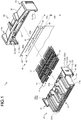
FIG. 1 is an exploded perspective view illustrating a connector of an embodiment; -
FIG. 2 is an exploded perspective view of the connector of the embodiment when viewed at a different angle; -
FIG. 3 is an exploded perspective view of the connector before cover connection; -
FIG. 4 is an exploded perspective view of the connector before cover connection when viewed at a different angle; -
FIG. 5 is a perspective view illustrating the connector of the embodiment; -
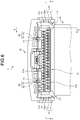
FIG. 6 is a plan view illustrating the connector of the embodiment; -
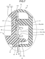
FIG. 7 is a partially enlarged diagram of a section taken along line X-X inFIG. 6 ; -
FIG. 8 is an enlarged view of Part A inFIG. 2 ; -
FIG. 9 is a partially enlarged diagram of a section taken along line Y-Y inFIG. 6 ; -
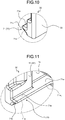
FIG. 10 is an enlarged view of Part B inFIG. 3 ; -
FIG. 11 is an enlarged view of Part C inFIG. 3 ; -
FIG. 12 is an enlarged view of Part D inFIG. 3 ; -
FIG. 13 is an enlarged view of Part E inFIG. 4 ; -
FIG. 14 is an enlarged view of Part F inFIG. 6 ; -
FIG. 15 is a perspective view illustrating a cover; and -
FIG. 16 is an enlarged view of Part G inFIG. 15 . - An embodiment of a connector according to the present invention will be described below in detail with reference to the accompanying drawings. The present embodiment does not limit the present invention.
- One embodiment of the connector according to the present invention will be described below based on
FIGS. 1 to 16 . -
Reference sign 1 inFIGS. 1 to 6 denotes the connector of the present embodiment. Thisconnector 1 includes aterminal clasp 10, ahousing 20 in which theterminal clasp 10 is stored and that is fitted and connected to a counterpart housing (not illustrated) of a counterpart connector in a fitting connection direction, and acover 30 that is connected with thehousing 20 through insertion and covers, from outside, at least part of thehousing 20 and a conductive part (to be described later) protruding from the housing 20 (FIGS. 1 and2 ). - The
terminal clasp 10 is formed of a conductive material such as metal. For example, theterminal clasp 10 is formed of a metal plate as a parent material through press fabrication such as bending and cutting. Theterminal clasp 10 includes aterminal connection part 11 that is physically and electrically connected with a counterpart terminal clasp (not illustrated) of the counterpart connector, and anelectrical connection part 12 that is physically and electrically connected with a sheet conductive component 40 (FIGS. 1 and2 ). Theterminal connection part 11 is formed in, for example, a female terminal shape or a male terminal shape. - The sheet
conductive component 40 is a flexible flat conductive component disposed outside thehousing body 21 and connected with theelectrical connection part 12 protruding out of thehousing body 21. The flexible flat conductive component is a conductive component in which a conductor and an insulator that are flexible (in other words, plastic) are stacked and formed in a flat plane. - For example, the flexible flat conductive component includes a plurality of conductors each forming a circuit pattern. The flexible flat conductive component is, for example, a flexible printed circuit substrate (FPC), a printing circuit structure such as a membrane wiring plate, a flat cable (FC), or a flexible flat cable (FFC).
- The
connector 1 of the present embodiment includes one or a plurality ofterminal clasps 10. Theconnector 1 of this example includes a plurality ofterminal clasps 10, and theelectrical connection part 12 of eachterminal clasp 10 is physically and electrically connected with a rectangular flexible flat conductive component as theconductive component 40. In this example, each conductor (not illustrated) of theconductive component 40 is provided with oneterminal clasp 10. Theelectrical connection part 12 of theterminal clasp 10 is provided perpendicular to the flat plane of theconductive component 40 by inserting theelectrical connection part 12 into a through-hole 41 of theconductive component 40 and soldering theelectrical connection part 12 to the conductor exposed at the through-hole 41 (FIGS. 1 ,2 , and4 ). In theconductive component 40 of this example, theterminal clasps 10 are connected at one (side 40a) of the four sides of the conductive component 40 (FIGS. 1 ,2 , and4 ), and accordingly, the electrical connection parts of the conductors are disposed at theside 40a. - The
conductive component 40 includes, on theside 40a of the rectangle, anelectrical connection region 40a1 in which theelectrical connection part 12 of eachterminal clasp 10 is connected with the electrical connection part of the corresponding conductor, and aperipheral region 40a2 enclosing theelectrical connection region 40a1 (FIGS. 1 ,2 , and4 ). In theelectrical connection region 40a1, a through-hole 41 is formed for the electrical connection part of each conductor (theelectrical connection part 12 of each terminal clasp 10). Theconductive component 40 also includes anextension region 40b extending out of thehousing 20 and thecover 30 connected with each other (FIGS. 1 ,2 , and4 ). - The
housing 20 is formed of an insulating material such as synthesis resin. Thehousing 20 includes a storage room 20a in which theterminal connection part 11 of eachterminal clasp 10 is stored, and an opening 20b communicated with the storage room 20a (FIG. 2 ). Theterminal connection part 11 is stored into the storage room 20a through the opening 20b. Thehousing 20 of this example includes ahousing body 21 in which theterminal clasps 10 are stored (FIGS. 1 to 6 ). In thehousing body 21, the storage room 20a and the opening 20b are formed for eachterminal clasp 10. Theterminal connection part 11 is inserted into the storage room 20a of thehousing body 21 through theopening 20b in the fitting connection direction. - In this example, the
housing body 21 is formed in a rectangular parallelepiped shape. Theterminal connection part 11 of eachterminal clasp 10 is stored in the storage room 20a in thehousing body 21, and theelectrical connection part 12 thereof protrudes out of one (firstouter wall surface 21a (FIGS. 1 to 3 )) of six outer wall surfaces. In this example, theopening 20b of each storage room 20a is provided to the firstouter wall surface 21a, and theelectrical connection part 12 protrudes through the opening 20b toward a first wall 31 (to be described later) of thecover 30 in a direction opposite to the fitting connection direction. - The flat plane of the
side 40a (theelectrical connection region 40a1 and theperipheral region 40a2) of theconductive component 40 is disposed opposite to and placed on the firstouter wall surface 21a. In this manner, the firstouter wall surface 21a is used as an installation surface for the flat plane of theside 40a (theelectrical connection region 40a1 and theperipheral region 40a2) .
When theconductive component 40 is placed on the firstouter wall surface 21a, eachelectrical connection part 12 protruding through thecorresponding opening 20b is inserted into the through-hole 41. Eachelectrical connection part 12 is soldered to the electrical connection part of the corresponding conductor on theside 40a of theconductive component 40 outside thehousing body 21. Theextension region 40b of theconductive component 40 extends on a secondouter wall surface 21b side of thehousing body 21, which is disposed orthogonal to the firstouter wall surface 21a (FIGS. 1 to 4 ). - The
conductive component 40 has at least twofitting holes 42 provided on theextension region 40b side in theperipheral region 40a2 (FIGS. 1 and2 ). Thehousing 20 includes afitting protrusion 22 that is provided for eachfitting hole 42 and fitted into thefitting hole 42 without backlash (FIGS. 1 ,2 , and4 ). Eachfitting protrusion 22 is provided for the correspondingfitting hole 42 perpendicularly from the firstouter wall surface 21a as the installation surface in thehousing body 21. - In the
connector 1, when theside 40a (theelectrical connection region 40a1 and theperipheral region 40a2) of theconductive component 40 is placed on the firstouter wall surface 21a as the installation surface, eachelectrical connection part 12 protruding through thecorresponding opening 20b is inserted into the through-hole 41, and eachfitting protrusion 22 is fitted into the corresponding fitting hole 42 (FIGS. 4 and7 ). Accordingly, in theconnector 1, when force such as pulling force is applied to theextension region 40b of theconductive component 40, the force is transferred from the periphery of eachfitting hole 42 to the outer peripheral surface of the correspondingfitting protrusion 22. Thus, in theconnector 1, the force applied to theextension region 40b can be received by thefitting protrusions 22. As a result, in theconnector 1, the force is prevented from being transferred to theelectrical connection region 40a1, thus reducing application of load to a place where theelectrical connection part 12 of eachterminal clasp 10 is connected with the electrical connection part of the corresponding conductor in theconductive component 40. Accordingly, theconnector 1 can reduce the load on the connection place and thus can achieve stabilization of the quality of energization between eachterminal clasp 10 and theconductive component 40. - The fitting holes 42 are desirably provided at two corner parts, respectively, on the
extension region 40b side of theperipheral region 40a2, the two corner parts being arranged in a direction orthogonal to a direction in which theextension region 40b extends. For example, in theconnector 1, when afitting hole 42 is provided only at a center on theextension region 40b side of theperipheral region 40a2 in the direction orthogonal to the extension direction, force applied to theextension region 40b is potentially transferred to theelectrical connection region 40a1 through corner parts. However, in theconnector 1, when the fitting holes 42 are provided at the two corner parts, eachfitting protrusion 22 is fitted into thefitting hole 42 at the corresponding corner part, and force applied to theextension region 40b can be received by thefitting protrusion 22 at the corner part. Thus, with such disposition of the fitting holes 42, theconnector 1 can achieve a high effect of reducing a load on the place where theelectrical connection part 12 of eachterminal clasp 10 is connected with the electrical connection part of the corresponding conductor in theconductive component 40, thereby achieving further stabilization of the quality of energization between eachterminal clasp 10 and theconductive component 40. - In the
connector 1 of this example, two pairs of afitting hole 42 and the correspondingfitting protrusion 22 are provided at the respective corner parts. Eachfitting hole 42 of this example is formed as a circular through-hole (FIGS. 1 and2 ). Eachfitting protrusion 22 of this example includes acylindrical shaft 22a having a leading end formed in a circular truncated cone shape and having a diameter smaller than that of the correspondingfitting hole 42, and afitting part 22b that is formed in a cylindrical shape having a diameter larger than that of theshaft 22a and is fitted into thefitting hole 42 without backlash (FIGS. 7 and8 ). - The
housing body 21 includes a thirdouter wall surface 21c and a fourthouter wall surface 21d that are disposed orthogonal to the firstouter wall surface 21a and the secondouter wall surface 21b (FIGS. 1 to 3 ). Thehousing 20 covers and hides theelectrical connection part 12 of eachterminal clasp 10 and theside 40a (in other words, the electrical connection part of each conductor) of theconductive component 40 from the thirdouter wall surface 21c side and the fourthouter wall surface 21d side, thereby protecting these components. For this, thehousing 20 includes afirst protection body 23 disposed opposite to and coupled with the thirdouter wall surface 21c at an interval, and asecond protection body 24 disposed opposite to and coupled with the fourthouter wall surface 21d at an interval and protruding further than the firstouter wall surface 21a (FIGS. 1 to 4 and6 ). - The
first protection body 23 of this example includes aflat plate part 23a having a rectangular flat plate shape, and the flat plane of theflat plate part 23a is disposed opposite to the thirdouter wall surface 21c at an interval (FIGS. 1 to 4 and6 ). In thefirst protection body 23, theflat plate part 23a includes aprotrusion part 23a1 protruding further than the firstouter wall surface 21a, and theprotrusion part 23a1 covers and hides theelectrical connection part 12 of eachterminal clasp 10 and theside 40a of theconductive component 40 from the thirdouter wall surface 21c side (FIGS. 1 to 4 ). Thesecond protection body 24 of this example includes aflat plate part 24a having a rectangular flat plate shape, and the flat plane of theflat plate part 24a is disposed opposite to the fourthouter wall surface 21d at an interval (FIGS. 1 to 4 and6 ). In thesecond protection body 24, theflat plate part 24a includes aprotrusion part 24a1 protruding further than the firstouter wall surface 21a, and theprotrusion part 24a1 covers and hides theelectrical connection part 12 of eachterminal clasp 10 and theside 40a of theconductive component 40 from the fourthouter wall surface 21d side (FIGS. 1 to 4 ). - In the
housing 20, a plurality ofreinforcement ribs 25 are provided to the housing body 21 (FIGS. 3 to 6 ). Thereinforcement ribs 25 protrude on a fifthouter wall surface 21e of thehousing body 21. The fifthouter wall surface 21e is an outer wall surface of thehousing body 21, which is disposed orthogonal to the firstouter wall surface 21a and disposed on a side opposite to the secondouter wall surface 21b. - The
cover 30 is formed of an insulating material such as synthesis resin. The conductive part covered by thecover 30 is theelectrical connection part 12 protruding out of thehousing body 21 and theside 40a of the flexible flat conductive component as theconductive component 40. In this example, the conductive part covered by thecover 30 is theelectrical connection part 12 of eachterminal clasp 10 and theside 40a of the conductive component 40 (electrical connection part of each conductor). Thecover 30 covers and hides, with thefirst wall 31 and asecond wall 32, theelectrical connection part 12 of eachterminal clasp 10 and theside 40a of theconductive component 40, thereby protecting these components (FIGS. 1 to 4 ). Thefirst wall 31 is disposed opposite to the firstouter wall surface 21a at an interval, thereby covering and hiding theelectrical connection part 12 of eachterminal clasp 10 and theside 40a of theconductive component 40. Thesecond wall 32 is provided continuously with thefirst wall 31 and disposed opposite to the fifthouter wall surface 21e at an interval, thereby covering and hiding theelectrical connection part 12 of eachterminal clasp 10 and theside 40a of theconductive component 40 from the fifthouter wall surface 21e side. - In addition, the
cover 30 includes athird wall 33 disposed opposite to thefirst protection body 23 of thehousing 20 to cover thefirst protection body 23 from outside, and afourth wall 34 disposed opposite to thesecond protection body 24 of thehousing 20 to cover thesecond protection body 24 from outside (FIGS. 1 to 4 ). Thethird wall 33 and thefourth wall 34 of this example are formed in rectangular flat plate shapes and flexible. - The
housing 20 and thecover 30 are inserted and connected with each other in the direction orthogonal to the firstouter wall surface 21a. In this example, thehousing 20 is inserted and connected with thecover 30 from the firstouter wall surface 21a side in a direction opposite to the fitting connection direction. When the insertion and connection of thehousing 20 and thecover 30 are performed up to a connection completed position, the firstouter wall surface 21a and thefirst wall 31 are positioned opposite to each other, the fifthouter wall surface 21e and thesecond wall 32 are positioned opposite to each other, thefirst protection body 23 and thethird wall 33 are positioned opposite to each other, and thesecond protection body 24 and thefourth wall 34 are positioned opposite to each other. - A locking structure (hereinafter referred to as "first locking structure") 50 configured to lock motion of the housing and the cover opposite to the connection direction at the connection completed position is provided between the
housing 20 and the cover 30 (FIGS. 1 to 3 and9 ). Thefirst locking structure 50 includes afirst lock body 51 provided to thehousing 20, and asecond lock body 52 provided to the cover 30 (FIGS. 1 ,3 , and9 ). Thefirst lock body 51 and thesecond lock body 52 are disposed opposite to each other to lock motion of thehousing 20 and thecover 30 opposite to the connection direction when thehousing 20 and thecover 30 are at the connection completed position. - In the
connector 1 of the present embodiment, thefirst locking structures 50 are provided at two places: between thefirst protection body 23 and thethird wall 33 and between thesecond protection body 24 and thefourth wall 34. In this example, eachfirst lock body 51 is formed as a protrusion, and eachsecond lock body 52 is formed as a lock wall that is engaged with thefirst lock body 51. Thefirst lock body 51 protrudes outward from the outer wall surface of the corresponding one of thefirst protection body 23 and thesecond protection body 24. Thesecond lock body 52 is formed at the inner wall surface of the corresponding one of thethird wall 33 and thefourth wall 34. Thefirst locking structures 50 at the two places are provided so that thefirst lock bodies 51 thereof protrude in directions opposite to each other. - In addition, a locking structure (hereinafter referred to as "second locking structure") 60 configured to lock motion of the
housing 20 and thecover 30 in a separation direction among directions orthogonal to the connection direction at the connection completed position is provided between thehousing 20 and the cover 30 (FIGS. 3 to 6 ). Thesecond locking structure 60 includes afirst lock body 61 provided to thehousing 20, and asecond lock body 62 provided to the cover 30 (FIGS. 3 and6 ). - In the
second locking structure 60 of this example, thefirst lock body 61 as a protrusion protrudes from thereinforcement ribs 25, and thesecond lock body 62 as a lock groove that is engaged with thefirst lock body 61 is formed at thesecond wall 32 of thecover 30. Thefirst lock body 61 and thesecond lock body 62 each have a stereoscopic shape having a substantially trapezoid section orthogonal to the connection direction of thehousing 20 and thecover 30 and extending in the connection direction. In each of thefirst lock body 61 and thesecond lock body 62, the upper base of the substantially trapezoid orthogonal section is positioned on the fifthouter wall surface 21e side. With this configuration, thefirst lock body 61 and thesecond lock body 62 lock motion of thehousing 20 and thecover 30 in the separation direction when thehousing 20 and thecover 30 are at the connection completed position. Thefirst lock body 61 and thesecond lock body 62 also serve as a guiding structure for connecting thehousing 20 and thecover 30 through insertion. Theconnector 1 of the present embodiment includes thesecond locking structures 60 at two places. - In addition, a guiding
structure 70 configured to guide thehousing 20 and thecover 30 in the connection direction is provided between thehousing 20 and the cover 30 (FIGS. 1 to 6 and10 to 14 ). The guidingstructure 70 includes awedge guiding protrusion 71 that is a protrusion provided to one of thehousing 20 and thecover 30, has a wedge-shaped section orthogonal to the connection direction, and extends in the connection direction, and awedge guiding groove 72 that is a groove provided to the other of thehousing 20 and thecover 30, has a wedge-shaped section orthogonal to the connection direction, and extends in the connection direction to guide and be guided by thewedge guiding protrusion 71 being inserted in the connection direction (FIGS. 1 ,3 ,5 ,6 , and14 ). - The
wedge guiding protrusion 71 and thewedge guiding groove 72 are formed to have two pairs of a protrusion-side wall surface 71a and a groove-side wall surface 72a disposed opposite to each other (FIGS. 10 to 14 ) and have a gap between the protrusion-side wall surface 71a and the groove-side wall surface 72a of each pair. - The
wedge guiding protrusion 71 of this example has aleading end 71b at the starting point of insertion into thewedge guiding groove 72 in the connection direction (FIGS. 10 and 11 ). Thewedge guiding groove 72 of this example has a leading end at aninsertion opening 72b through which thewedge guiding protrusion 71 is inserted in the connection direction from theleading end 71b, and has aback end 72c at a place where theleading end 71b of thewedge guiding protrusion 71 is inserted when thehousing 20 and thecover 30 move to the connection completed position (FIGS. 12 and 13 ). The protrusion-side wall surface 71a of thewedge guiding protrusion 71 includes aback end part 71a1 that is inserted through theinsertion opening 72b when thehousing 20 and thecover 30 move to the connection completed position and is positioned opposite to the groove-side wall surface 72a of thewedge guiding groove 72 after thehousing 20 and thecover 30 have moved to the connection completed position (FIG. 11 ). The groove-side wall surface 72a of thewedge guiding groove 72 includes, at theback end 72c of thewedge guiding groove 72, aback end part 72a1 that is positioned opposite to the protrusion-side wall surface 71a of theleading end 71b of thewedge guiding protrusion 71 after thehousing 20 and thecover 30 have moved to the connection completed position (FIGS. 12 and 13 ). - The guiding
structures 70 are provided at two places between thehousing 20 and thecover 30 of this example. The guidingstructures 70 at the two places are provided so that thewedge guiding protrusions 71 protrude in directions opposite to each other. Thewedge guiding protrusions 71 of this example are provided to thethird wall 33 and thefourth wall 34 of thecover 30. In this example, thewedge guiding protrusions 71 are disposed opposite to each other and formed at sides of the rectangularthird wall 33 and the rectangularfourth wall 34. Thewedge guiding grooves 72 of this example are provided to thefirst protection body 23 and thesecond protection body 24 of thehousing 20. Thewedge guiding groove 72 of thefirst protection body 23 is disposed adjacent to theflat plate part 23a in the flat plane direction of theflat plate part 23a. Thewedge guiding groove 72 of thesecond protection body 24 is disposed adjacent to theflat plate part 24a in the flat plane direction of theflat plate part 24a. - In addition, a holding
structure 80 configured to hold thehousing 20 and thecover 30 at the connection completed position is provided between thehousing 20 and the cover 30 (FIGS. 1 to 4 and12 to 14 ). The holdingstructure 80 includes a press-fit protrusion 81 on at least one of the protrusion-side wall surface 71a and the groove-side wall surface 72a disposed opposite to each other in at least one of the two pairs, the press-fit protrusion 81 being configured to hold the correspondingwedge guiding protrusion 71 andgroove 72 in a press-fitted state when thehousing 20 and thecover 30 are at the connection completed position. Accordingly, in theconnector 1, backlash due to the gap between eachwedge guiding protrusion 71 and the correspondingwedge guiding groove 72 is reduced when thehousing 20 and thecover 30 are at the connection completed position. Thus, in theconnector 1, generation of unnecessary sound between thehousing 20 and thecover 30, for example, when an external input due to vehicle driving or the like is applied is reduced. Moreover, in theconnector 1, generation of vibration of thehousing 20 and thecover 30 attributable to backlash when such an external input is applied is reduced, and thus degradation of durability of thehousing 20 and thecover 30 can be reduced. Accordingly, theconnector 1 of the present embodiment can have improved sound-vibration reduction capability. - The holding
structures 80 of this example are provided to the guidingstructures 70 at the two places. In this example, the press-fit protrusion 81 is formed as a protrusion on one of the two groove-side wall surfaces 72a of thewedge guiding groove 72 of each of the guidingstructures 70 at the two places. - The press-
fit protrusion 81 is desirably disposed to provide a gutter along the gap between thewedge guiding protrusion 71 and thewedge guiding groove 72 until thehousing 20 and thecover 30 move to the connection completed position and to hold thewedge guiding protrusion 71 and thewedge guiding groove 72 in a press-fitted state after thehousing 20 and thecover 30 have moved to the connection completed position. For example, the press-fit protrusion 81 is provided to theback end part 71a1 of the protrusion-side wall surface 71a when provided to the protrusion-side wall surface 71a, or is provided to theback end part 72a1 of the groove-side wall surface 72a when provided to the groove-side wall surface 72a. Accordingly, in theconnector 1, friction resistance between thewedge guiding protrusion 71 and thewedge guiding groove 72 is reduced until thehousing 20 and thecover 30 move to the connection completed position. In particular, in theconnector 1, thewedge guiding protrusion 71 and thewedge guiding groove 72 have wedge shapes in each of the guidingstructures 70 at the two places. Thus, the number of wall surfaces (pairs of the protrusion-side wall surface 71a and the groove-side wall surface 72a disposed opposite to each other) that are likely to contact at connection through insertion is four, which is a small number, and accordingly, the effect of reducing friction resistance between thewedge guiding protrusion 71 and thewedge guiding groove 72 is high. Thus, in theconnector 1, insertion force when thehousing 20 and thecover 30 are to be connected with each other through insertion is reduced until thehousing 20 and thecover 30 move to the connection completed position, which leads to improved operability of connecting thehousing 20 and thecover 30. Moreover, in theconnector 1, the wedge guiding protruded 71 and thewedge guiding groove 72 are held in a press-fitted state by the press-fit protrusion 81 after thehousing 20 and thecover 30 have moved to the connection completed position, which can reduce backlash between thewedge guiding protrusion 71 and thewedge guiding groove 72. Thus, in theconnector 1, the generation of unnecessary sound and the generation of vibration described above when thehousing 20 and thecover 30 are at the connection completed position can be reduced. In this manner, theconnector 1 can achieve both improvement of the operability of connecting thehousing 20 and thecover 30 and improvement of the sound-vibration reduction capability. - In this example, the press-
fit protrusion 81 is provided to theback end part 72a1 of the groove-side wall surface 72a (FIGS. 12 and 13 ). - The
housing 20 and thecover 30 are connected with each other through insertion and fixed to each other by press fitting in this manner. In theconnector 1 of the present embodiment, protrusions on thecover 30 side are inserted into through-holes of theconductive component 40 when thehousing 20 and thecover 30 are at the connection completed position after the insertion connection. For this, theconductive component 40 includes at least two through-holes 43 provided on a side opposite to theextension region 40b side in theperipheral region 40a2 (FIGS. 1 ,2 , and4 ). Thecover 30 includes aprotrusion 35 that is perpendicularly provided for each through-hole 43 and inserted into the corresponding through-hole 43 with play when thehousing 20 and thecover 30 are at the connection completed position (FIGS. 7 ,15 , and16 ). Theprotrusion 35 includes aleading end part 35a that protrudes out of the through-hole 43 when thehousing 20 and thecover 30 are at the connection completed position, and aback end part 35b that is inserted into the through-hole 43 in this case (FIGS. 7 and16 ). In thehousing body 21, agroove part 26 into which theleading end part 35a of theprotrusion 35 protruding out of the through-hole 43 enters is formed to prevent theleading end part 35a from contacting the firstouter wall surface 21a (FIG. 7 ). - In the
connector 1, eachprotrusion 35 is inserted into the corresponding through-hole 43 from theleading end part 35a as thehousing 20 and thecover 30 are connected with each other through insertion. In theconnector 1, play based on the maximum value of tolerance variance is provided between the through-hole 43 and theprotrusion 35. With this configuration, in theconnector 1, theprotrusion 35 can be inserted into the through-hole 43 as thehousing 20 and thecover 30 are connected with each other through insertion. - In the
connector 1, when theelectrical connection part 12 of eachterminal clasp 10 is soldered to the corresponding conductor of theconductive component 40, theside 40a (theelectrical connection region 40a1 and theperipheral region 40a2) of theconductive component 40 placed on the firstouter wall surface 21a as the installation surface is pressed against the firstouter wall surface 21a by a jig or the like. However, in theconnector 1, since thefitting protrusions 22, which are fitted on theextension region 40b side in theperipheral region 40a2 of theconductive component 40, are already provided on thehousing 20 side, theside 40a potentially cannot be pressed by a jig or the like or a region on which the pressing is performed is potentially restricted when theprotrusions 35 on the side opposite to theextension region 40b side in theperipheral region 40a2 are provided on thehousing 20 side. In addition, theprotrusions 35 provided on thehousing 20 side potentially interfere with a nozzle of a soldering device or the like. Thus, theprotrusions 35 are provided to thecover 30 in theconnector 1. With this configuration, theconnector 1 can prevent degradation of the quality of connection between theelectrical connection part 12 of eachterminal clasp 10 and the electrical connection part of the corresponding conductor in theconductive component 40. - In the
connector 1 of the present embodiment, the side opposite to theextension region 40b side in theperipheral region 40a2 of theconductive component 40 may be sandwiched between thehousing 20 and thecover 30 when thehousing 20 and thecover 30 are at the connection completed position, thereby further reducing the load on the place where theelectrical connection part 12 of eachterminal clasp 10 is connected with the electrical connection part of the corresponding conductor in theconductive component 40. To achieve this, thecover 30 includes alock part 36 that presses the periphery of each through-hole 43 in theperipheral region 40a2 against the firstouter wall surface 21a as the installation surface when thehousing 20 and thecover 30 are at the connection completed position (FIGS. 7 ,15 , and16 ). - In the
connector 1, when thehousing 20 and thecover 30 are at the connection completed position, eachlock part 36 of thecover 30 presses the periphery of the corresponding through-hole 43 in theperipheral region 40a2 against the firstouter wall surface 21a as the installation surface so that the periphery of the through-hole 43 is sandwiched between thelock part 36 and the firstouter wall surface 21a. Accordingly, in theconnector 1, when pulling force or force opposite to the pulling force is applied to theextension region 40b of theconductive component 40, the effect of reducing transfer of the force to theelectrical connection region 40a1 is enhanced, thereby further reducing the application of load to the place where theelectrical connection part 12 of eachterminal clasp 10 is connected with the electrical connection part of the corresponding conductor in theconductive component 40. In this manner, theconnector 1 can further reduce the load on the connection place, thereby achieving further stabilization of the quality of energization between eachterminal clasp 10 and theconductive component 40. In addition, in theconnector 1, since backlash between thehousing 20 and thecover 30 is reduced by the holdingstructure 80, the sandwiched state of theconductive component 40 by the through-holes 43, theprotrusions 35, and thelock parts 36 can be maintained. In this manner, theconnector 1 can maintain the stabilized quality of energization between eachterminal clasp 10 and theconductive component 40. - The through-
holes 43 are desirably provided at two corner parts, respectively, on the side opposite to theextension region 40b side in theperipheral region 40a2, the two corner parts being arranged in the direction orthogonal to the extension direction of theextension region 40b. Accordingly, theconductive component 40 is held while theelectrical connection region 40a1 is surrounded by thelock parts 36, the fitting holes 42, and thefitting protrusions 22 at four corners. Thus, theconnector 1 can achieve a high effect of reducing a load on the place where theelectrical connection part 12 of eachterminal clasp 10 is connected with the electrical connection part of the corresponding conductor in theconductive component 40, thereby achieving further stabilization of the quality of energization between eachterminal clasp 10 and theconductive component 40. - In the
connector 1 of this example, two sets of a through-hole 43, aprotrusion 35, and alock part 36 are provided at the two corner parts, respectively. The through-hole 43 of this example is formed as a circular through-hole (FIGS. 1 and2 ). In theprotrusion 35 of this example, theleading end part 35a is formed in a cylindrical shape having a leading end of a circular truncated cone shape and having a diameter smaller than that of the through-hole 43. Theback end part 35b is formed in a circular truncated cone shape having a diameter that increases as the position moves toward the base and that is smaller than that of the through-hole 43 (FIGS. 7 and16 ). - As described above, when force is applied to the
extension region 40b of theconductive component 40 in theconnector 1 of the present embodiment, a reduced load is applied, along with the force, on the place where theelectrical connection part 12 of eachterminal clasp 10 is connected with the electrical connection part of the corresponding conductor in theconductive component 40. Thus, theconnector 1 can achieve stabilization of the quality of energization between eachterminal clasp 10 and theconductive component 40. - In a connector according to the embodiment, when force such as pulling force is applied to the extension region of the conductive component, the force is transferred from the periphery of each fitting hole to the outer peripheral surface of the corresponding fitting protrusion. Accordingly, in the connector, the force applied to the extension region can be received by the fitting protrusion. Thus, in the connector, the force is prevented from being transferred to the electrical connection region, which reduces application of load to the place where the electrical connection part of each terminal clasp is connected with the electrical connection part of the corresponding conductor in the conductive component. In this manner, the connector according to the present embodiment can reduce a load on the connection place, thereby achieving stabilization of the quality of energization between each terminal clasp and the conductive component.
- Although the invention has been described with respect to specific embodiments for a complete and clear disclosure, the appended claims are not to be thus limited but are to be construed as embodying all modifications and alternative constructions that may occur to one skilled in the art that fairly fall within the basic teaching herein set forth.
Claims (6)
- A connector (1) comprising:a terminal clasp (10);a flexible flat conductive component (40) in which a conductor and an insulator that are flexible are stacked and formed in a flat plane, the conductor being connected with an electrical connection part (12) of the terminal clasp (10) provided perpendicular to the plane;a housing (20) in which a terminal connection part (11) of the terminal clasp (10) is stored in a storage room (20a) and the electrical connection part (12) of the terminal clasp (10) protrudes out of an opening (20b) of the storage room (20a); anda cover (30) that is connected with the housing (20) through insertion and covers the electrical connection part (12) from outside together with at least part of the housing (20), whereinthe flexible flat conductive component (40) includes an electrical connection region (40a1) in which the electrical connection part (12) is connected with the conductor, a peripheral region (40a2) enclosing the electrical connection region (40a1), an extension region (40b) extending out of the housing (20) and the cover (30) connected with each other, and at least two fitting holes (42) provided on the extension region (40b) side in the peripheral region (40a2), andthe housing (20) includes an installation surface (21a) through which the opening (20b) of the storage room (20a) is provided and on which flat planes of the electrical connection region (40a1) and the peripheral region (40a2) are placed, and a fitting protrusion (22) that is provided for each fitting hole (42) perpendicularly from the installation surface (21a) and is fitted into the fitting hole (42) without backlash.
- The connector according to claim 1, wherein
the fitting holes (42) are provided at two corner parts, respectively, on the extension region (40b) side in the peripheral region (40a2), the two corner parts being arranged in a direction orthogonal to a direction in which the extension region (40b) extends. - The connector according to claim 1 or 2, wherein
the flexible flat conductive component (40) includes at least two through-holes (43) provided on a side opposite to the extension region (40b) side in the peripheral region (40a2), and
the cover (30) includes a protrusion (35) that is perpendicularly provided for each through-hole (43) and inserted into the through-hole (43) with play when the housing (20) and the cover (30) are at a connection completed position. - The connector according to claim 3, wherein
the cover (30) includes a lock part (36) that presses a periphery of each through-hole (43) in the peripheral region (40a2) against the installation surface (21a) when the housing (20) and the cover (30) are at the connection completed position. - The connector according to claim 4, wherein
a holding structure (80) configured to hold the housing (20) and the cover (30) at the connection completed position is provided between the housing (20) and the cover (30). - The connector according to any one of claims 3, 4, and 5, wherein
the through-holes (43) are provided at two corner parts, respectively, on the side opposite to the extension region (40b) side in the peripheral region (40a2), the two corner parts being arranged in a direction orthogonal to a direction in which the extension region (40b) extends.
Applications Claiming Priority (1)
| Application Number | Priority Date | Filing Date | Title |
|---|---|---|---|
| JP2019189379A JP7094641B2 (en) | 2019-10-16 | 2019-10-16 | connector |
Publications (2)
| Publication Number | Publication Date |
|---|---|
| EP3809530A1 true EP3809530A1 (en) | 2021-04-21 |
| EP3809530B1 EP3809530B1 (en) | 2022-07-20 |
Family
ID=72852403
Family Applications (1)
| Application Number | Title | Priority Date | Filing Date |
|---|---|---|---|
| EP20201423.9A Active EP3809530B1 (en) | 2019-10-16 | 2020-10-13 | Electrical connector |
Country Status (4)
| Country | Link |
|---|---|
| US (1) | US11239583B2 (en) |
| EP (1) | EP3809530B1 (en) |
| JP (1) | JP7094641B2 (en) |
| CN (1) | CN112670758B (en) |
Families Citing this family (4)
| Publication number | Priority date | Publication date | Assignee | Title |
|---|---|---|---|---|
| TWI733227B (en) * | 2019-10-25 | 2021-07-11 | 群光電能科技股份有限公司 | Housing device with combining structures |
| JP7219250B2 (en) * | 2020-07-27 | 2023-02-07 | 矢崎総業株式会社 | connector |
| JP2022105807A (en) * | 2021-01-05 | 2022-07-15 | 株式会社オートネットワーク技術研究所 | Sheet conductive path |
| CA3243555A1 (en) * | 2022-08-11 | 2025-04-10 | Lg Energy Solution, Ltd. | Connector module and battery module including the same |
Citations (10)
| Publication number | Priority date | Publication date | Assignee | Title |
|---|---|---|---|---|
| EP1923958A1 (en) * | 2006-11-17 | 2008-05-21 | Tyco Electronics AMP K.K. | Electrical connector for flat cable |
| JP2014017361A (en) | 2012-07-09 | 2014-01-30 | Yazaki Corp | Connection terminal structure of ffc/fpc |
| JP2014093123A (en) | 2012-10-31 | 2014-05-19 | Tyco Electronics Japan Kk | Flat cable connector |
| WO2015002144A1 (en) * | 2013-07-03 | 2015-01-08 | 矢崎総業株式会社 | Connection structure for flat circuit body and connector |
| WO2016088308A1 (en) * | 2014-12-05 | 2016-06-09 | パナソニックIpマネジメント株式会社 | Plug connector and connector set |
| JP2016110994A (en) | 2014-12-05 | 2016-06-20 | パナソニックIpマネジメント株式会社 | Plug connector and connector set |
| US9735486B1 (en) * | 2016-05-06 | 2017-08-15 | Alltop Electronics (Suzhou) Ltd. | Electrical connector |
| JP2019106347A (en) | 2017-12-14 | 2019-06-27 | 日本圧着端子製造株式会社 | FPC connector |
| JP2019106368A (en) | 2017-12-11 | 2019-06-27 | ヨンホ エムエス.Yeonho Ms. | Electric connector assembly |
| EP3605741A1 (en) * | 2018-07-31 | 2020-02-05 | Yazaki Corporation | Connector-attached circuit body and bus bar module |
Family Cites Families (10)
| Publication number | Priority date | Publication date | Assignee | Title |
|---|---|---|---|---|
| GB2261558B (en) * | 1991-10-31 | 1996-07-10 | Sumitomo Wiring Systems | A connector assembly |
| JP2827635B2 (en) * | 1991-10-31 | 1998-11-25 | 住友電装株式会社 | Connector structure for flexible wiring board |
| US6010359A (en) * | 1998-07-08 | 2000-01-04 | Molex Incorporated | Electrical connector system for shielded flat flexible circuitry |
| JP2002025667A (en) * | 2000-07-11 | 2002-01-25 | Hirose Electric Co Ltd | Flat cable connector |
| JP2002124340A (en) * | 2000-10-17 | 2002-04-26 | Yazaki Corp | Flat cable connector |
| JP2006294386A (en) * | 2005-04-08 | 2006-10-26 | Tyco Electronics Amp Kk | Electric connector, wire harness and method for wire harness arrangement |
| DE102005027852A1 (en) * | 2005-06-16 | 2006-12-21 | Robert Bosch Gmbh | Arrangement and method for the electrical connection of an electronic circuit in a housing |
| WO2009050779A1 (en) * | 2007-10-15 | 2009-04-23 | Fujitsu Limited | Printed board unit and electronic device |
| CN102315549B (en) * | 2010-07-02 | 2013-08-21 | 艾恩特精密工业股份有限公司 | Electrical connector with encapsulating injection molding material and assembly method thereof |
| CN102332660B (en) * | 2010-07-13 | 2014-05-07 | 富士康(昆山)电脑接插件有限公司 | Cable connector assembly |
-
2019
- 2019-10-16 JP JP2019189379A patent/JP7094641B2/en active Active
-
2020
- 2020-10-13 EP EP20201423.9A patent/EP3809530B1/en active Active
- 2020-10-14 US US17/069,874 patent/US11239583B2/en active Active
- 2020-10-15 CN CN202011104652.1A patent/CN112670758B/en active Active
Patent Citations (10)
| Publication number | Priority date | Publication date | Assignee | Title |
|---|---|---|---|---|
| EP1923958A1 (en) * | 2006-11-17 | 2008-05-21 | Tyco Electronics AMP K.K. | Electrical connector for flat cable |
| JP2014017361A (en) | 2012-07-09 | 2014-01-30 | Yazaki Corp | Connection terminal structure of ffc/fpc |
| JP2014093123A (en) | 2012-10-31 | 2014-05-19 | Tyco Electronics Japan Kk | Flat cable connector |
| WO2015002144A1 (en) * | 2013-07-03 | 2015-01-08 | 矢崎総業株式会社 | Connection structure for flat circuit body and connector |
| WO2016088308A1 (en) * | 2014-12-05 | 2016-06-09 | パナソニックIpマネジメント株式会社 | Plug connector and connector set |
| JP2016110994A (en) | 2014-12-05 | 2016-06-20 | パナソニックIpマネジメント株式会社 | Plug connector and connector set |
| US9735486B1 (en) * | 2016-05-06 | 2017-08-15 | Alltop Electronics (Suzhou) Ltd. | Electrical connector |
| JP2019106368A (en) | 2017-12-11 | 2019-06-27 | ヨンホ エムエス.Yeonho Ms. | Electric connector assembly |
| JP2019106347A (en) | 2017-12-14 | 2019-06-27 | 日本圧着端子製造株式会社 | FPC connector |
| EP3605741A1 (en) * | 2018-07-31 | 2020-02-05 | Yazaki Corporation | Connector-attached circuit body and bus bar module |
Also Published As
| Publication number | Publication date |
|---|---|
| JP7094641B2 (en) | 2022-07-04 |
| CN112670758A (en) | 2021-04-16 |
| US20210119359A1 (en) | 2021-04-22 |
| JP2021064571A (en) | 2021-04-22 |
| CN112670758B (en) | 2022-06-10 |
| US11239583B2 (en) | 2022-02-01 |
| EP3809530B1 (en) | 2022-07-20 |
Similar Documents
| Publication | Publication Date | Title |
|---|---|---|
| EP3809530B1 (en) | Electrical connector | |
| JP4522144B2 (en) | Electrical connector | |
| JP7196028B2 (en) | connector assembly | |
| EP4012851B1 (en) | Connector | |
| WO2021045091A1 (en) | Socket and electronic device | |
| JP7655777B2 (en) | Terminals, wire connectors and wire-to-board connectors | |
| CN119542792A (en) | Connector components | |
| EP3809533B1 (en) | Electrical connector | |
| JP4789576B2 (en) | Electrical connector | |
| US11742604B2 (en) | Easy lock connector with unlock structure | |
| JP2009048941A (en) | Connector device | |
| EP3809529B1 (en) | Connector | |
| US20230261426A1 (en) | First connector and connector module | |
| JP3422380B2 (en) | Connector structure | |
| JP7705595B2 (en) | Electrical connector and electrical connector assembly | |
| JP4807780B2 (en) | Connector device | |
| US12413000B2 (en) | Flat conductor electric connector | |
| US20250246827A1 (en) | Wire harness | |
| JP2025074473A (en) | Floating connector and connector device | |
| JP2025074517A (en) | Connector device | |
| JP2007128662A (en) | Module fixing method for socket type connector and module / connector assembly | |
| JP4845116B2 (en) | Connector device | |
| KR20220130570A (en) | board connector | |
| JP2007012574A (en) | Connector device | |
| KR20220002512U (en) | Press component and connector thereof |
Legal Events
| Date | Code | Title | Description |
|---|---|---|---|
| PUAI | Public reference made under article 153(3) epc to a published international application that has entered the european phase |
Free format text: ORIGINAL CODE: 0009012 |
|
| STAA | Information on the status of an ep patent application or granted ep patent |
Free format text: STATUS: REQUEST FOR EXAMINATION WAS MADE |
|
| 17P | Request for examination filed |
Effective date: 20201013 |
|
| AK | Designated contracting states |
Kind code of ref document: A1 Designated state(s): AL AT BE BG CH CY CZ DE DK EE ES FI FR GB GR HR HU IE IS IT LI LT LU LV MC MK MT NL NO PL PT RO RS SE SI SK SM TR |
|
| AX | Request for extension of the european patent |
Extension state: BA ME |
|
| GRAP | Despatch of communication of intention to grant a patent |
Free format text: ORIGINAL CODE: EPIDOSNIGR1 |
|
| STAA | Information on the status of an ep patent application or granted ep patent |
Free format text: STATUS: GRANT OF PATENT IS INTENDED |
|
| RIC1 | Information provided on ipc code assigned before grant |
Ipc: H01R 12/79 20110101ALN20220404BHEP Ipc: H01R 13/58 20060101ALN20220404BHEP Ipc: H01R 12/70 20110101ALI20220404BHEP Ipc: H01R 12/59 20110101ALI20220404BHEP Ipc: H01R 9/16 20060101ALI20220404BHEP Ipc: H01R 13/506 20060101ALI20220404BHEP Ipc: H01R 12/77 20110101AFI20220404BHEP |
|
| INTG | Intention to grant announced |
Effective date: 20220421 |
|
| GRAS | Grant fee paid |
Free format text: ORIGINAL CODE: EPIDOSNIGR3 |
|
| GRAA | (expected) grant |
Free format text: ORIGINAL CODE: 0009210 |
|
| STAA | Information on the status of an ep patent application or granted ep patent |
Free format text: STATUS: THE PATENT HAS BEEN GRANTED |
|
| AK | Designated contracting states |
Kind code of ref document: B1 Designated state(s): AL AT BE BG CH CY CZ DE DK EE ES FI FR GB GR HR HU IE IS IT LI LT LU LV MC MK MT NL NO PL PT RO RS SE SI SK SM TR |
|
| REG | Reference to a national code |
Ref country code: CH Ref legal event code: EP |
|
| REG | Reference to a national code |
Ref country code: DE Ref legal event code: R096 Ref document number: 602020004087 Country of ref document: DE |
|
| REG | Reference to a national code |
Ref country code: AT Ref legal event code: REF Ref document number: 1506147 Country of ref document: AT Kind code of ref document: T Effective date: 20220815 |
|
| REG | Reference to a national code |
Ref country code: IE Ref legal event code: FG4D |
|
| REG | Reference to a national code |
Ref country code: LT Ref legal event code: MG9D |
|
| REG | Reference to a national code |
Ref country code: NL Ref legal event code: MP Effective date: 20220720 |
|
| PG25 | Lapsed in a contracting state [announced via postgrant information from national office to epo] |
Ref country code: SE Free format text: LAPSE BECAUSE OF FAILURE TO SUBMIT A TRANSLATION OF THE DESCRIPTION OR TO PAY THE FEE WITHIN THE PRESCRIBED TIME-LIMIT Effective date: 20220720 Ref country code: RS Free format text: LAPSE BECAUSE OF FAILURE TO SUBMIT A TRANSLATION OF THE DESCRIPTION OR TO PAY THE FEE WITHIN THE PRESCRIBED TIME-LIMIT Effective date: 20220720 Ref country code: PT Free format text: LAPSE BECAUSE OF FAILURE TO SUBMIT A TRANSLATION OF THE DESCRIPTION OR TO PAY THE FEE WITHIN THE PRESCRIBED TIME-LIMIT Effective date: 20221121 Ref country code: NO Free format text: LAPSE BECAUSE OF FAILURE TO SUBMIT A TRANSLATION OF THE DESCRIPTION OR TO PAY THE FEE WITHIN THE PRESCRIBED TIME-LIMIT Effective date: 20221020 Ref country code: NL Free format text: LAPSE BECAUSE OF FAILURE TO SUBMIT A TRANSLATION OF THE DESCRIPTION OR TO PAY THE FEE WITHIN THE PRESCRIBED TIME-LIMIT Effective date: 20220720 Ref country code: LV Free format text: LAPSE BECAUSE OF FAILURE TO SUBMIT A TRANSLATION OF THE DESCRIPTION OR TO PAY THE FEE WITHIN THE PRESCRIBED TIME-LIMIT Effective date: 20220720 Ref country code: LT Free format text: LAPSE BECAUSE OF FAILURE TO SUBMIT A TRANSLATION OF THE DESCRIPTION OR TO PAY THE FEE WITHIN THE PRESCRIBED TIME-LIMIT Effective date: 20220720 Ref country code: FI Free format text: LAPSE BECAUSE OF FAILURE TO SUBMIT A TRANSLATION OF THE DESCRIPTION OR TO PAY THE FEE WITHIN THE PRESCRIBED TIME-LIMIT Effective date: 20220720 Ref country code: ES Free format text: LAPSE BECAUSE OF FAILURE TO SUBMIT A TRANSLATION OF THE DESCRIPTION OR TO PAY THE FEE WITHIN THE PRESCRIBED TIME-LIMIT Effective date: 20220720 |
|
| REG | Reference to a national code |
Ref country code: AT Ref legal event code: MK05 Ref document number: 1506147 Country of ref document: AT Kind code of ref document: T Effective date: 20220720 |
|
| PG25 | Lapsed in a contracting state [announced via postgrant information from national office to epo] |
Ref country code: PL Free format text: LAPSE BECAUSE OF FAILURE TO SUBMIT A TRANSLATION OF THE DESCRIPTION OR TO PAY THE FEE WITHIN THE PRESCRIBED TIME-LIMIT Effective date: 20220720 Ref country code: IS Free format text: LAPSE BECAUSE OF FAILURE TO SUBMIT A TRANSLATION OF THE DESCRIPTION OR TO PAY THE FEE WITHIN THE PRESCRIBED TIME-LIMIT Effective date: 20221120 Ref country code: HR Free format text: LAPSE BECAUSE OF FAILURE TO SUBMIT A TRANSLATION OF THE DESCRIPTION OR TO PAY THE FEE WITHIN THE PRESCRIBED TIME-LIMIT Effective date: 20220720 Ref country code: GR Free format text: LAPSE BECAUSE OF FAILURE TO SUBMIT A TRANSLATION OF THE DESCRIPTION OR TO PAY THE FEE WITHIN THE PRESCRIBED TIME-LIMIT Effective date: 20221021 |
|
| REG | Reference to a national code |
Ref country code: DE Ref legal event code: R097 Ref document number: 602020004087 Country of ref document: DE |
|
| PG25 | Lapsed in a contracting state [announced via postgrant information from national office to epo] |
Ref country code: SM Free format text: LAPSE BECAUSE OF FAILURE TO SUBMIT A TRANSLATION OF THE DESCRIPTION OR TO PAY THE FEE WITHIN THE PRESCRIBED TIME-LIMIT Effective date: 20220720 Ref country code: RO Free format text: LAPSE BECAUSE OF FAILURE TO SUBMIT A TRANSLATION OF THE DESCRIPTION OR TO PAY THE FEE WITHIN THE PRESCRIBED TIME-LIMIT Effective date: 20220720 Ref country code: DK Free format text: LAPSE BECAUSE OF FAILURE TO SUBMIT A TRANSLATION OF THE DESCRIPTION OR TO PAY THE FEE WITHIN THE PRESCRIBED TIME-LIMIT Effective date: 20220720 Ref country code: CZ Free format text: LAPSE BECAUSE OF FAILURE TO SUBMIT A TRANSLATION OF THE DESCRIPTION OR TO PAY THE FEE WITHIN THE PRESCRIBED TIME-LIMIT Effective date: 20220720 Ref country code: AT Free format text: LAPSE BECAUSE OF FAILURE TO SUBMIT A TRANSLATION OF THE DESCRIPTION OR TO PAY THE FEE WITHIN THE PRESCRIBED TIME-LIMIT Effective date: 20220720 |
|
| PLBE | No opposition filed within time limit |
Free format text: ORIGINAL CODE: 0009261 |
|
| STAA | Information on the status of an ep patent application or granted ep patent |
Free format text: STATUS: NO OPPOSITION FILED WITHIN TIME LIMIT |
|
| PG25 | Lapsed in a contracting state [announced via postgrant information from national office to epo] |
Ref country code: SK Free format text: LAPSE BECAUSE OF FAILURE TO SUBMIT A TRANSLATION OF THE DESCRIPTION OR TO PAY THE FEE WITHIN THE PRESCRIBED TIME-LIMIT Effective date: 20220720 Ref country code: MC Free format text: LAPSE BECAUSE OF FAILURE TO SUBMIT A TRANSLATION OF THE DESCRIPTION OR TO PAY THE FEE WITHIN THE PRESCRIBED TIME-LIMIT Effective date: 20220720 Ref country code: EE Free format text: LAPSE BECAUSE OF FAILURE TO SUBMIT A TRANSLATION OF THE DESCRIPTION OR TO PAY THE FEE WITHIN THE PRESCRIBED TIME-LIMIT Effective date: 20220720 |
|
| REG | Reference to a national code |
Ref country code: BE Ref legal event code: MM Effective date: 20221031 |
|
| 26N | No opposition filed |
Effective date: 20230421 |
|
| PG25 | Lapsed in a contracting state [announced via postgrant information from national office to epo] |
Ref country code: LU Free format text: LAPSE BECAUSE OF NON-PAYMENT OF DUE FEES Effective date: 20221013 Ref country code: AL Free format text: LAPSE BECAUSE OF FAILURE TO SUBMIT A TRANSLATION OF THE DESCRIPTION OR TO PAY THE FEE WITHIN THE PRESCRIBED TIME-LIMIT Effective date: 20220720 |
|
| PG25 | Lapsed in a contracting state [announced via postgrant information from national office to epo] |
Ref country code: FR Free format text: LAPSE BECAUSE OF NON-PAYMENT OF DUE FEES Effective date: 20221031 |
|
| PG25 | Lapsed in a contracting state [announced via postgrant information from national office to epo] |
Ref country code: SI Free format text: LAPSE BECAUSE OF FAILURE TO SUBMIT A TRANSLATION OF THE DESCRIPTION OR TO PAY THE FEE WITHIN THE PRESCRIBED TIME-LIMIT Effective date: 20220720 |
|
| PG25 | Lapsed in a contracting state [announced via postgrant information from national office to epo] |
Ref country code: BE Free format text: LAPSE BECAUSE OF NON-PAYMENT OF DUE FEES Effective date: 20221031 |
|
| PG25 | Lapsed in a contracting state [announced via postgrant information from national office to epo] |
Ref country code: IE Free format text: LAPSE BECAUSE OF NON-PAYMENT OF DUE FEES Effective date: 20221013 |
|
| PG25 | Lapsed in a contracting state [announced via postgrant information from national office to epo] |
Ref country code: CY Free format text: LAPSE BECAUSE OF FAILURE TO SUBMIT A TRANSLATION OF THE DESCRIPTION OR TO PAY THE FEE WITHIN THE PRESCRIBED TIME-LIMIT Effective date: 20220720 |
|
| PG25 | Lapsed in a contracting state [announced via postgrant information from national office to epo] |
Ref country code: MK Free format text: LAPSE BECAUSE OF FAILURE TO SUBMIT A TRANSLATION OF THE DESCRIPTION OR TO PAY THE FEE WITHIN THE PRESCRIBED TIME-LIMIT Effective date: 20220720 Ref country code: IT Free format text: LAPSE BECAUSE OF FAILURE TO SUBMIT A TRANSLATION OF THE DESCRIPTION OR TO PAY THE FEE WITHIN THE PRESCRIBED TIME-LIMIT Effective date: 20220720 |
|
| REG | Reference to a national code |
Ref country code: CH Ref legal event code: PL |
|
| PG25 | Lapsed in a contracting state [announced via postgrant information from national office to epo] |
Ref country code: TR Free format text: LAPSE BECAUSE OF FAILURE TO SUBMIT A TRANSLATION OF THE DESCRIPTION OR TO PAY THE FEE WITHIN THE PRESCRIBED TIME-LIMIT Effective date: 20220720 |
|
| PG25 | Lapsed in a contracting state [announced via postgrant information from national office to epo] |
Ref country code: CH Free format text: LAPSE BECAUSE OF NON-PAYMENT OF DUE FEES Effective date: 20231031 |
|
| PG25 | Lapsed in a contracting state [announced via postgrant information from national office to epo] |
Ref country code: HU Free format text: LAPSE BECAUSE OF FAILURE TO SUBMIT A TRANSLATION OF THE DESCRIPTION OR TO PAY THE FEE WITHIN THE PRESCRIBED TIME-LIMIT; INVALID AB INITIO Effective date: 20201013 Ref country code: CH Free format text: LAPSE BECAUSE OF NON-PAYMENT OF DUE FEES Effective date: 20231031 Ref country code: BG Free format text: LAPSE BECAUSE OF FAILURE TO SUBMIT A TRANSLATION OF THE DESCRIPTION OR TO PAY THE FEE WITHIN THE PRESCRIBED TIME-LIMIT Effective date: 20220720 |
|
| PG25 | Lapsed in a contracting state [announced via postgrant information from national office to epo] |
Ref country code: MT Free format text: LAPSE BECAUSE OF FAILURE TO SUBMIT A TRANSLATION OF THE DESCRIPTION OR TO PAY THE FEE WITHIN THE PRESCRIBED TIME-LIMIT Effective date: 20220720 |
|
| GBPC | Gb: european patent ceased through non-payment of renewal fee |
Effective date: 20241013 |
|
| PG25 | Lapsed in a contracting state [announced via postgrant information from national office to epo] |
Ref country code: GB Free format text: LAPSE BECAUSE OF NON-PAYMENT OF DUE FEES Effective date: 20241013 |
|
| PGFP | Annual fee paid to national office [announced via postgrant information from national office to epo] |
Ref country code: DE Payment date: 20250902 Year of fee payment: 6 |