EP3809438A1 - Multipurpose relay control - Google Patents
Multipurpose relay control Download PDFInfo
- Publication number
- EP3809438A1 EP3809438A1 EP19215805.3A EP19215805A EP3809438A1 EP 3809438 A1 EP3809438 A1 EP 3809438A1 EP 19215805 A EP19215805 A EP 19215805A EP 3809438 A1 EP3809438 A1 EP 3809438A1
- Authority
- EP
- European Patent Office
- Prior art keywords
- signal
- relay
- pulse
- latching
- receiving
- Prior art date
- Legal status (The legal status is an assumption and is not a legal conclusion. Google has not performed a legal analysis and makes no representation as to the accuracy of the status listed.)
- Granted
Links
Images
Classifications
-
- H—ELECTRICITY
- H01—ELECTRIC ELEMENTS
- H01H—ELECTRIC SWITCHES; RELAYS; SELECTORS; EMERGENCY PROTECTIVE DEVICES
- H01H51/00—Electromagnetic relays
- H01H51/02—Non-polarised relays
- H01H51/04—Non-polarised relays with single armature; with single set of ganged armatures
- H01H51/06—Armature is movable between two limit positions of rest and is moved in one direction due to energisation of an electromagnet and after the electromagnet is de-energised is returned by energy stored during the movement in the first direction, e.g. by using a spring, by using a permanent magnet, by gravity
- H01H51/10—Contacts retained open or closed by a latch which is controlled by an electromagnet
-
- H—ELECTRICITY
- H01—ELECTRIC ELEMENTS
- H01H—ELECTRIC SWITCHES; RELAYS; SELECTORS; EMERGENCY PROTECTIVE DEVICES
- H01H47/00—Circuit arrangements not adapted to a particular application of the relay and designed to obtain desired operating characteristics or to provide energising current
- H01H47/22—Circuit arrangements not adapted to a particular application of the relay and designed to obtain desired operating characteristics or to provide energising current for supplying energising current for relay coil
- H01H47/226—Circuit arrangements not adapted to a particular application of the relay and designed to obtain desired operating characteristics or to provide energising current for supplying energising current for relay coil for bistable relays
-
- G—PHYSICS
- G01—MEASURING; TESTING
- G01R—MEASURING ELECTRIC VARIABLES; MEASURING MAGNETIC VARIABLES
- G01R31/00—Arrangements for testing electric properties; Arrangements for locating electric faults; Arrangements for electrical testing characterised by what is being tested not provided for elsewhere
- G01R31/327—Testing of circuit interrupters, switches or circuit-breakers
- G01R31/3277—Testing of circuit interrupters, switches or circuit-breakers of low voltage devices, e.g. domestic or industrial devices, such as motor protections, relays, rotation switches
- G01R31/3278—Testing of circuit interrupters, switches or circuit-breakers of low voltage devices, e.g. domestic or industrial devices, such as motor protections, relays, rotation switches of relays, solenoids or reed switches
-
- H—ELECTRICITY
- H01—ELECTRIC ELEMENTS
- H01H—ELECTRIC SWITCHES; RELAYS; SELECTORS; EMERGENCY PROTECTIVE DEVICES
- H01H50/00—Details of electromagnetic relays
- H01H50/16—Magnetic circuit arrangements
- H01H50/18—Movable parts of magnetic circuits, e.g. armature
- H01H50/32—Latching movable parts mechanically
- H01H50/321—Latching movable parts mechanically the mechanical latch being controlled directly by the magnetic flux or part of it
-
- H—ELECTRICITY
- H01—ELECTRIC ELEMENTS
- H01H—ELECTRIC SWITCHES; RELAYS; SELECTORS; EMERGENCY PROTECTIVE DEVICES
- H01H51/00—Electromagnetic relays
- H01H51/02—Non-polarised relays
- H01H51/04—Non-polarised relays with single armature; with single set of ganged armatures
- H01H51/12—Armature is movable between two limit positions of rest and is moved in both directions due to the energisation of one or the other of two electromagnets without the storage of energy to effect the return movement
-
- H—ELECTRICITY
- H01—ELECTRIC ELEMENTS
- H01H—ELECTRIC SWITCHES; RELAYS; SELECTORS; EMERGENCY PROTECTIVE DEVICES
- H01H51/00—Electromagnetic relays
- H01H51/27—Relays with armature having two stable magnetic states and operated by change from one state to the other
-
- H—ELECTRICITY
- H03—ELECTRONIC CIRCUITRY
- H03K—PULSE TECHNIQUE
- H03K3/00—Circuits for generating electric pulses; Monostable, bistable or multistable circuits
- H03K3/78—Generating a single train of pulses having a predetermined pattern, e.g. a predetermined number
-
- H—ELECTRICITY
- H03—ELECTRONIC CIRCUITRY
- H03K—PULSE TECHNIQUE
- H03K5/00—Manipulating of pulses not covered by one of the other main groups of this subclass
- H03K5/13—Arrangements having a single output and transforming input signals into pulses delivered at desired time intervals
- H03K5/131—Digitally controlled
-
- H—ELECTRICITY
- H03—ELECTRONIC CIRCUITRY
- H03K—PULSE TECHNIQUE
- H03K2217/00—Indexing scheme related to electronic switching or gating, i.e. not by contact-making or -breaking covered by H03K17/00
- H03K2217/94—Indexing scheme related to electronic switching or gating, i.e. not by contact-making or -breaking covered by H03K17/00 characterised by the way in which the control signal is generated
- H03K2217/94052—Indexing scheme related to electronic switching or gating, i.e. not by contact-making or -breaking covered by H03K17/00 characterised by the way in which the control signal is generated with evaluation of actuation pattern or sequence, e.g. tapping
Definitions
- the present disclosure relates generally to relays, and in particular, to a system for controlling the behavior of an electromagnetic relay.
- Relays are known in the electrical art as being electromagnetic switches that can receive a control current to operate electrically-isolated electrical contacts to control a separate current path. Therefore, a relay can be used to provide a high degree of electrical isolation between a first circuit (i.e., control circuit) and a second circuit (i.e., load circuit). Moreover, a relay can be used to control a load current (i.e., second circuit) that is significantly larger than the control current (i.e., first circuit).
- Two known types of relays are conventional relays and latching relays, each having an operating characteristic that can be relevant to a particular application.
- relays in a manufacturing setting, relays must be procured by specifying the quantities of conventional relays and latching relays that will be required for production of a particular application which uses both types of relays. This can be disadvantageous, particularly when the final circuit application of one or more relays (i.e., conventional or latching) is subject to design changes. Accordingly, there is a need for a system that can control the behavior of an electrical relay having a single design, thereby allowing a particular relay to be programmed to behave as either a conventional relay or as a latching relay.
- a relay configured for use in electrical circuits that are configured to employ at least one conventional relay and/or are configured to employ at least one latching relay, the relay having a first operating mode in which the relay behaves as the conventional relay, and a second operating mode in which the relay behaves as a latching relay.
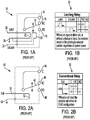
- FIG. 1A is an electrical schematic diagram of a latching relay of the prior art. Shown in FIGS. 1A - 1B are latching relay 10, contactor 12, common contact 14, normally closed contact 16, normally open contact 18, latching control terminal 20, latching coil 22, unlatching control terminal 24, unlatching coil 26, common control terminal 28, and logic state diagram 30.
- Latching relay 10 includes contactor 12 which makes electrical contact between common contact 14 and either normally closed (NC) contact 16 or normally open (NO) contact 18, depending on the condition of latching relay 10, as will be described. When a latching current pulse is applied to latching control terminal 20, latching coil 22 is energized thereby drawing contactor 12 toward NC contact 16, creating an electrical connection between common contact 14 and NC contact 16.
- latching relay 10 is said to be in the latched condition. In the latched condition, there is not an electrical connection between common contact 14 and NO contact 18.
- Latching relay 10 is depicted in the latched condition in FIG. 1A . Latching relay 10 transitions to the latched condition during the application of the latching current pulse. Latching relay 10 remains in the latched condition after the latching current pulse subsides (i.e., returns to zero).
- unlatching coil 26 is energized thereby drawing contactor 12 toward NO contact 18, creating an electrical connection between common contact 14 and NO contact 18. Accordingly, latching relay 10 is said to be in the unlatched condition. In the unlatched condition, there is not an electrical connection between common contact 14 and NC contact 16.
- common control terminal 28 is a ground connection, providing a common signal path for both latching control terminal 20 and unlatching control terminal 24.
- FIG. 1B is a logic state diagram for latching relay 10 shown in FIG. 1A .
- the behavior of latching relay 10, as was described above in regard to FIG. 1A is depicted in logic state diagram 30.
- Latching relay 10 can be used when a control system (not shown in FIG. 1A ) generates control pulses that are used to change the condition of latching relay 10.
- Latching relay 10 can be referred to as a bi-stable switch (i.e., having two stable conditions).
- An advantage of using latching relay 10 is that under steady-state conditions (i.e., when not receiving a latching current pulse or an unlatching current pulse), neither latching coil 22 nor unlatching coil 26 are energized. In some applications, for example, where a power budget is critical, it can be advantageous that latching coil 22 and unlatching coil 26 remain de-energized during steady-state conditions.
- FIG. 2A is an electrical schematic diagram of a conventional relay of the prior art. Shown in FIG. 2A are conventional relay 40, contactor 42, common contact 44, normally closed contact 46, normally open contact 48, control terminal 50, control coil 52, and common control terminal 54.
- Conventional relay 40 includes contactor 42 which makes electrical contact between common contact 44 and normally closed (NC) contact 46 or normally open (NO) contact 48, depending on the condition of control coil 52, as will be described.
- a control current i.e., energizing current
- control coil 52 is energized thereby drawing contactor 42 toward NO contact 48, creating an electrical connection between common contact 44 and NO contact 48. Accordingly, conventional relay 40 is said to be in the energized condition.
- Conventional relay 40 is depicted in the de-energized condition in FIG. 2A .
- the de-energized condition can be referred to as the "normal” condition in conventional relay 40, thereby explaining the conventions used in labeling normally closed and normally open contacts (e.g., NC contact 46, NO contact 48).
- Conventional relay 40 can also be referred to as a normal relay.
- Common control terminal 54 is so named because it provides a common (i.e., ground) connection for control coil 52.
- FIG. 2B is a logic state diagram for conventional relay 40 shown in FIG. 2A .
- the behavior of conventional relay 40 as was described above in regard to FIG. 2A is depicted in logic state diagram 60.
- Conventional relay 40 can be used when a control system (not shown in FIG. 2A ) generates an output current that represents the current that is intended to be supplied to a load.
- Conventional relay 40 can be referred to as a mono-stable switch (i.e., having one stable condition).
- An advantage of using conventional relay 40 is the design simplicity, whereby a control current condition (i.e., on or off) can be used to control a load condition (i.e., on or off). In some applications, for example, where it is desirable that a load remain energized only when a control current is present, it can be advantageous that conventional relay 40 return to the normal (i.e., de-energized) condition when the control current is lost.
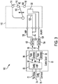
- FIG. 3 is a schematic block diagram of a relay behavior-changing controller.
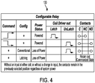
- FIG. 4 is a logic state diagram for a latching relay connected to the relay behavior-changing controller shown in FIG. 3 . Shown in FIGS. 3 - 4 are controller 70, power status input 72, configuration status input 74, command input 76, configuration logic 80, latching control signal 82, latching pulse generator 84, latching pulse signal 86, unlatching control signal 88, unlatching pulse generator 90, unlatching pulse signal 92, relay system 100, latching coil driver 102, unlatching coil driver 104, configurable relay 110, contactor 112, common contact 114, normally closed contact 116, normally open contact 118, latching control terminal 120, latching coil 122, unlatching control terminal 124, unlatching coil 126, common control terminal 128, and logic state diagram 130.
- Controller 70 can be referred to as a control circuit or as a relay behavior-changing controller.
- Configuration logic 80 within controller 70 receives three input signals: power status input 72, configuration status input 74, and command input 76. A description will first be made of the operation of other aspects of control circuit 70 within relay system 100.
- Configuration logic 80 i.e., "config logic" is configured to produce latching control signal 82 and unlatching control signal 88 when it is desired to latch or unlatch configurable relay 110, respectively.
- Latching control signal 82 when generated, is input to latching pulse generator 84 which in turn provides latching pulse signal 86 to latching coil driver 102, thereby delivering a latching current pulse to latching control terminal 120 of configurable relay 110.
- unlatching control signal 88 when generated, is input to unlatching pulse generator 90 which in turn provides unlatching pulse signal 92 to unlatching coil driver 104, thereby delivering an unlatching current pulse to unlatching control terminal 124 of configurable relay 110.
- Latching and unlatching pulse generators 84, 90 can be referred to as monostable multivibrators or as "one-shots", because they generate an output pulse of a defined duration when triggered, then return to their resting condition.
- configurable relay 110 is a latching relay at the component level.
- a latching relay can also be referred to as a bi-stable relay, as a "keep” relay", and as a “stay” relay, because it keeps (i.e., stays) in a particular condition after being activated by a signal (e.g., latch or unlatch signal).
- Configurable relay 110 includes contactor 112 which makes an electrical contact via contactor 112 between common contact 114 and either normally closed (NC) contact 116 or normally open (NO) contact 118, depending on the condition of configurable relay 110.
- a latching current pulse is applied to latching control terminal 120, latching coil 122 is energized thereby drawing contactor 112 toward NC contact 116, creating an electrical connection between common contact 114 and NC contact 116.
- configurable relay 110 can be said to be latched, or in a latched condition.
- the latched condition can also be referred to as a first condition.
- Configurable relay 110 is depicted in the latched (i.e., first) condition in FIG. 3 .
- unlatching current pulse When an unlatching current pulse is applied to unlatching control terminal 124, unlatching coil 126 is energized thereby drawing contactor 112 toward NO contact 118, creating an electrical connection between common contact 114 and NO contact 118. Accordingly, relay 10 is said to be in the unlatched condition.
- the unlatched condition can also be referred to as a second condition.
- common control terminal 128 is a ground connection, providing a common signal path for both latching control terminal 120 and unlatching control terminal 124.
- configurable relay 110 includes common contact 114 which makes an electrical connection via contactor 112 with either NC contact 116 or NO contact 118.
- Configurable relay 110 can be described as having a single switching pole, and as being a single-pole double-throw (SPDT) switch. In some embodiments, more than a single switching pole (i.e., pole) of contacts can be used. For example, two switching poles (i.e., two contactors 112) can be connected by a common actuator (not shown in FIG. 3 ), resulting in a double-pole double-throw (DPDT) switch. Typically, each switching pole will have a separate contactor 112 that is electrically isolated from the others.
- a two-pole relay (i.e., DPDT) can be used to control two load circuits (not shown in FIG. 3 ).
- a first pole can control a load current
- a second pole can control a feedback circuit that provides an indication of the condition of configurable relay 110 to a different circuit (not shown in FIG. 3 ).
- three or more poles can be used in configurable relay 110.
- configurable relay 110 can be referred to as an NPDT switch where N represents the number of switching poles, which can include any number of switching poles.
- the present disclosure includes any number of switching poles in configurable relay 110.
- NC contact 116 or NO contact 118 can be omitted from one or more switching poles of configurable relay 110.
- configurable relay 110 can include a single switching pole having common contact 114 and a single other contact (i.e., either NC contact 116 or NO contact 118).
- configurable relay 110 can be referred to as a single-pole single-throw (SPST) switch.
- configuration logic 80 can receive power status input 72, configuration status input 74, and command input 76, as noted earlier.
- Power status input is either “powered” or “unpowered” (i.e., loss of power).
- Configuration status input 74 is either "conventional” (i.e., normal) or "latching", depending on the relay type that configurable relay 110 is configured to behave as.
- Providing a "conventional” input at configuration status input 74 can be referred to as a first operating condition of configurable relay 110, and providing a "latching" input at configuration status input 74 can be referred to as a second operating condition of configurable relay 110.
- Command input 76 is either a "low-to-high” or a "high-to-low” signal transition, as desired to change the condition of configurable relay 110.
- the behavior of configurable relay 110 can be made to function as a latching relay by providing a "latching" input at configuration status input 74. Under the "latching" input condition, an unpowered (i.e., loss of power) input at power status input 72 has no effect, and configuration logic 80 does not produce any signal output. Accordingly, the position of contactor 112 in configurable relay 110 does not change when power status input is unpowered (i.e., loss of power), and the configuration of common contact 114, NC contact 116, and NO contact 118 remains the same as shown in logic state diagram 130.
- control circuit 70 When control circuit 70 is configured for configurable relay 110 to emulate the function of a conventional relay (i.e., configuration status input 74 is "conventional"), a powered input signal at power status input 72 will cause configuration logic 80 to generate an output signal at latching control signal 82, thereby directing a latching current pulse to latching coil 122.
- configuration logic 80 When the powered input signal is removed at power status input 72 (i.e., loss of power), configuration logic 80 will generate an output signal at unlatching control signal 88, thereby directing an unlatching current pulse to unlatching coil 126, as described above.
- Providing a "latching" input at configuration status input 74 will configure control circuit 70 to emulate the function of a latching relay (i.e., the second operating condition of configurable relay 110). Accordingly, a "low-to-high” signal at command input 76 will cause configuration logic 80 to produce latching control signal 82, thereby directing a latching current pulse to latching coil 122, causing configurable relay 110 to transition to a latched condition as described above. Similarly, a "high-to-low” signal at command input 76 will cause configuration logic 80 to produce unlatching control signal 88, thereby directing an unlatching current pulse to unlatching coil 126, causing configurable relay 110 to transition to an unlatched condition as described above.
- controller 70 of the present embodiment is particularly adapted for a latch-unlatch signal residing on a single input line (i.e., command input 76). In other embodiments, controller 70 can be adapted to receive discrete "latch" and "unlatch” signals. Being a latching relay, configurable relay 110 requires two commands to function (i.e., latch and unlatch).
- controller 70 allows configurable relay 110 (i.e., a latching relay) to emulate the behavior of a conventional relay when configuration status input 74 is "normal" (i.e., conventional). In other words, controller 70 allows a latching relay to be used as a conventional relay, if so desired.
- configuration logic 80 uses configuration status input 74 to determine in what state to leave configurable relay 110 when power is eventually lost (i.e., latched or unlatched). If configuration status input 74 is "latching”, then configuration logic 82 leaves configurable relay 110 in its current state (i.e., latched or unlatched). If configuration status input 74 is "conventional”, then, at the point of power loss, configuration logic 80 commands will command configurable relay 110 to the NO condition (i.e., unlatched), thereby emulating a conventional relay.
- configurable relay 110 can be controlled at any time during the operation of relay system 100 by changing the input to configuration status input 74 (i.e., from “conventional” to “latching", or from “latching” to “conventional”). Accordingly, configurable relay 110 can be said to be reconfigurable “on the fly” during the operation of relay system 100, thereby providing operational flexibility.
- controller 70 shown in FIGS. 3 - 4 is to provide the designer the flexibility to develop and manufacture a single component design for configurable relay 110 which can then be configured to behave as (i.e., emulate) either a conventional or a latching relay. In some situations, significant time and effort can be avoided that would otherwise need to be used in developing and manufacturing two relay component designs (i.e., conventional and latching relays). It can be appreciated that in some situations, critical component specifications can require long and involved procurement lifecycles. Non-limiting examples of critical component specifications include materials selection, packaging design, quality criteria, reliability and testing requirements, and vendor qualification.
- controller 70 can be helpful in maximizing the design flexibility involving relay components.
- a method of controlling a behavior of a relay configured to receive a latch command for entering into a latch condition and an unlatch command for entering into an unlatch condition, the method comprising: receiving, by a logic controller, a configuration signal comprising either a first behavior signal or a second behavior signal; receiving, by the logic controller, a power status signal comprising either a powered signal or an unpowerered signal; receiving, by the logic controller, a command signal comprising either a low-to-high signal or a high-to-low signal; generating, by a first pulse generator communicatively coupled to the logic controller, a latching pulse in response to receiving a powered signal input as the power status signal and a low-to-high signal as the command signal input; generating, by a second pulse generator communicatively coupled to the logic controller, an unlatching pulse in response to receiving a powered signal input as the power status signal and a high-to-low signal as the command signal input; and generating, by the second pulse generator communicatively coupled to the logic
- a further embodiment of the foregoing method further comprising: generating, by a first coil driver configured to receive the latching pulse from the first pulse generator, a latching current pulse in response to receiving the latching pulse; and generating, by a second coil driver configured to receive the unlatching pulse from the second pulse generator, an unlatching current pulse in response to receiving the unlatching pulse.
- a further embodiment of the foregoing method further comprising: applying, to a latching coil on the relay, the latching current pulse, thereby directing the relay into a latched condition; and applying, to an unlatching coil on the relay, the unlatching current pulse, thereby directing the relay into an unlatched condition.
- a system for controlling a behavior of a relay configured to receive a latch command for entering into a latch condition and an unlatch command for entering into an unlatch condition
- the system comprising: a logic controller, configured to receive: a configuration signal input comprising either a first behavior signal or a second behavior signal; a power status signal input comprising either a powered signal or an unpowerered signal; and a command signal input comprising either a low-to-high signal or a high-to-low signal; a first pulse generator, configured to generate a latching pulse in response to receiving a powered signal input as the power status signal and a low-to-high signal as the command signal input; and a second pulse generator, configured to generate an unlatching pulse in response to: receiving a powered signal input as the power status signal and a high-to-low signal as the command signal input; or receiving the second behavior signal as the configuration signal and the unpowered signal as the power status signal.
- a further embodiment of the foregoing system further comprising: a first coil driver, configured to: receive the latching pulse from the first pulse generator; and generate a latching current pulse in response to receiving the latching pulse; and a second coil driver, configured to: receive the unlatching pulse from the second pulse generator; and generate an unlatching current pulse in response to receiving the unlatching pulse.
- a relay configured for use in electrical circuits that are configured to employ at least one conventional relay and/or are configured to employ at least one latching relay, the relay having a first operating mode in which the relay behaves as the conventional relay, and a second operating mode in which the relay behaves as a latching relay.
- the relay of the preceding paragraph can optionally include, additionally and/or alternatively, any one or more of the following features, configurations and/or additional components:
- a further embodiment of the foregoing relay wherein the relay is configured to be used in an electrical circuit regardless of whether the electrical circuit is configured to employ a conventional relay that requires electrical power to maintain a first position instead of a second position or a latching relay configured to remain in a previous position regardless of whether electrical power is actively being applied.
- a further embodiment of the foregoing relay further comprising: a latching coil, configured to receive a latch command for entering the relay into a latched condition; and an unlatching coil, configured to receive an unlatch command for entering the relay into an unlatched condition; wherein: the relay is configured to receive the latch command from a first pulse generator configured to generate a latching pulse in response to receiving a powered signal input as a power status signal and a low-to-high signal as a command signal input; and the relay is configured to receive the unlatch command from a second pulse generator configured to generate an unlatching pulse in response to: receiving a powered signal input as the power status signal and a high-to-low signal as the command signal input; or receiving a second behavior signal as a configuration signal and an unpowered signal as the power status signal.
Landscapes
- Physics & Mathematics (AREA)
- Electromagnetism (AREA)
- Nonlinear Science (AREA)
- General Physics & Mathematics (AREA)
- Relay Circuits (AREA)
Abstract
Description
- The present disclosure relates generally to relays, and in particular, to a system for controlling the behavior of an electromagnetic relay.
- Relays are known in the electrical art as being electromagnetic switches that can receive a control current to operate electrically-isolated electrical contacts to control a separate current path. Therefore, a relay can be used to provide a high degree of electrical isolation between a first circuit (i.e., control circuit) and a second circuit (i.e., load circuit). Moreover, a relay can be used to control a load current (i.e., second circuit) that is significantly larger than the control current (i.e., first circuit). Two known types of relays are conventional relays and latching relays, each having an operating characteristic that can be relevant to a particular application. Therefore, in a manufacturing setting, relays must be procured by specifying the quantities of conventional relays and latching relays that will be required for production of a particular application which uses both types of relays. This can be disadvantageous, particularly when the final circuit application of one or more relays (i.e., conventional or latching) is subject to design changes. Accordingly, there is a need for a system that can control the behavior of an electrical relay having a single design, thereby allowing a particular relay to be programmed to behave as either a conventional relay or as a latching relay.
- A method of controlling a behavior of a relay configured to receive a latch command for entering into a latch condition and an unlatch command for entering into an unlatch condition includes receiving, by a logic controller, a configuration signal comprising either a first behavior signal or a second behavior signal, receiving, by the logic controller, a power status signal comprising either a powered signal or an unpowerered signal, receiving, by the logic controller, a command signal comprising either a low-to-high signal or a high-to-low signal, generating, by a first pulse generator communicatively coupled to the logic controller, a latching pulse in response to receiving a powered signal input as the power status signal and a low-to-high signal as the command signal input, generating, by a second pulse generator communicatively coupled to the logic controller, an unlatching pulse in response to receiving a powered signal input as the power status signal and a high-to-low signal as the command signal input, and generating, by the second pulse generator communicatively coupled to the logic controller, the unlatching pulse in response to receiving the second behavior signal as the configuration signal and the unpowered signal as the power status signal.
- A system for controlling a behavior of a relay configured to receive a latch command for entering into a latch condition and an unlatch command for entering into an unlatch condition includes a logic controller, configured to receive a configuration signal input comprising either a first behavior signal or a second behavior signal, a power status signal input comprising either a powered signal or an unpowerered signal, and a command signal input comprising either a low-to-high signal or a high-to-low signal, a first pulse generator configured to generate a latching pulse in response to receiving a powered signal input as the power status signal and a low-to-high signal as the command signal input, and a second pulse generator configured to generate an unlatching pulse in response to receiving a powered signal input as the power status signal and a high-to-low signal as the command signal input or receiving the second behavior signal as the configuration signal and the unpowered signal as the power status signal.
- A relay configured for use in electrical circuits that are configured to employ at least one conventional relay and/or are configured to employ at least one latching relay, the relay having a first operating mode in which the relay behaves as the conventional relay, and a second operating mode in which the relay behaves as a latching relay.
-
-
FIG. 1A is an electrical schematic diagram of a latching relay of the prior art. -
FIG. 1B is a logic state diagram for the latching relay shown inFIG. 1A . -
FIG. 2A is an electrical schematic diagram of a conventional relay of the prior art. -
FIG. 2B is a logic state diagram for the conventional relay shown inFIG. 2A . -
FIG. 3 is a schematic block diagram of a relay behavior-changing controller. -
FIG. 4 is a logic state diagram for a latching relay connected to the relay behavior-changing controller shown inFIG. 4 . -
FIG. 1A is an electrical schematic diagram of a latching relay of the prior art. Shown inFIGS. 1A - 1B arelatching relay 10,contactor 12,common contact 14, normally closedcontact 16, normallyopen contact 18,latching control terminal 20,latching coil 22,unlatching control terminal 24,unlatching coil 26,common control terminal 28, and logic state diagram 30.Latching relay 10 includescontactor 12 which makes electrical contact betweencommon contact 14 and either normally closed (NC)contact 16 or normally open (NO)contact 18, depending on the condition oflatching relay 10, as will be described. When a latching current pulse is applied tolatching control terminal 20,latching coil 22 is energized thereby drawingcontactor 12 towardNC contact 16, creating an electrical connection betweencommon contact 14 andNC contact 16. Accordingly,latching relay 10 is said to be in the latched condition. In the latched condition, there is not an electrical connection betweencommon contact 14 and NOcontact 18.Latching relay 10 is depicted in the latched condition inFIG. 1A . Latching relay 10 transitions to the latched condition during the application of the latching current pulse.Latching relay 10 remains in the latched condition after the latching current pulse subsides (i.e., returns to zero). When an unlatching current pulse is applied to unlatchingcontrol terminal 24,unlatching coil 26 is energized thereby drawingcontactor 12 toward NOcontact 18, creating an electrical connection betweencommon contact 14 and NOcontact 18. Accordingly,latching relay 10 is said to be in the unlatched condition. In the unlatched condition, there is not an electrical connection betweencommon contact 14 and NCcontact 16. In the illustrated embodiment,common control terminal 28 is a ground connection, providing a common signal path for bothlatching control terminal 20 andunlatching control terminal 24. -
FIG. 1B is a logic state diagram forlatching relay 10 shown inFIG. 1A . The behavior oflatching relay 10, as was described above in regard toFIG. 1A , is depicted in logic state diagram 30.Latching relay 10 can be used when a control system (not shown inFIG. 1A ) generates control pulses that are used to change the condition oflatching relay 10.Latching relay 10 can be referred to as a bi-stable switch (i.e., having two stable conditions). An advantage of usinglatching relay 10 is that under steady-state conditions (i.e., when not receiving a latching current pulse or an unlatching current pulse), neitherlatching coil 22 norunlatching coil 26 are energized. In some applications, for example, where a power budget is critical, it can be advantageous thatlatching coil 22 andunlatching coil 26 remain de-energized during steady-state conditions. -
FIG. 2A is an electrical schematic diagram of a conventional relay of the prior art. Shown inFIG. 2A areconventional relay 40, contactor 42, common contact 44, normally closedcontact 46, normally open contact 48,control terminal 50,control coil 52, andcommon control terminal 54.Conventional relay 40 includes contactor 42 which makes electrical contact between common contact 44 and normally closed (NC)contact 46 or normally open (NO) contact 48, depending on the condition ofcontrol coil 52, as will be described. When a control current (i.e., energizing current) is applied tocontrol terminal 50,control coil 52 is energized thereby drawing contactor 42 toward NO contact 48, creating an electrical connection between common contact 44 and NO contact 48. Accordingly,conventional relay 40 is said to be in the energized condition. In the energized condition, there is not an electrical connection between common contact 44 and NCcontact 46.Conventional relay 40 remains in the energized condition so long as the control current is applied tocontrol terminal 50. Whencontrol terminal 50 is de-energized (i.e., the control current is removed),conventional relay 40 returns to the de-energized condition. In the de-energized condition, an electrical connection is made between common contact 44 and NCcontact 46, and the electrical connection between common contact 44 and NO contact 48 is broken. In a typical embodiment, a mechanical spring (not shown inFIG. 2A ) is compressed by contactor 42 when contactor 42 is drawn to NO contact 48 bycontrol coil 52. Therefore, whencontrol coil 52 is de-energized, the mechanical spring forces contactor 42 to return toNC contact 46.Conventional relay 40 is depicted in the de-energized condition inFIG. 2A . The de-energized condition can be referred to as the "normal" condition inconventional relay 40, thereby explaining the conventions used in labeling normally closed and normally open contacts (e.g.,NC contact 46, NO contact 48).Conventional relay 40 can also be referred to as a normal relay.Common control terminal 54 is so named because it provides a common (i.e., ground) connection forcontrol coil 52. -
FIG. 2B is a logic state diagram forconventional relay 40 shown inFIG. 2A . The behavior ofconventional relay 40 as was described above in regard toFIG. 2A is depicted in logic state diagram 60.Conventional relay 40 can be used when a control system (not shown inFIG. 2A ) generates an output current that represents the current that is intended to be supplied to a load.Conventional relay 40 can be referred to as a mono-stable switch (i.e., having one stable condition). An advantage of usingconventional relay 40 is the design simplicity, whereby a control current condition (i.e., on or off) can be used to control a load condition (i.e., on or off). In some applications, for example, where it is desirable that a load remain energized only when a control current is present, it can be advantageous thatconventional relay 40 return to the normal (i.e., de-energized) condition when the control current is lost. -
FIG. 3 is a schematic block diagram of a relay behavior-changing controller.FIG. 4 is a logic state diagram for a latching relay connected to the relay behavior-changing controller shown inFIG. 3 . Shown inFIGS. 3 - 4 arecontroller 70, power status input 72,configuration status input 74,command input 76,configuration logic 80, latchingcontrol signal 82, latchingpulse generator 84, latching pulse signal 86, unlatching control signal 88, unlatchingpulse generator 90, unlatchingpulse signal 92,relay system 100, latchingcoil driver 102, unlatchingcoil driver 104,configurable relay 110,contactor 112,common contact 114, normallyclosed contact 116, normallyopen contact 118, latchingcontrol terminal 120, latchingcoil 122, unlatchingcontrol terminal 124, unlatchingcoil 126,common control terminal 128, and logic state diagram 130. Reference will be made to logic state diagram 130 inFIG. 4 while describingrelay system 100 inFIG. 3 .Controller 70 can be referred to as a control circuit or as a relay behavior-changing controller.Configuration logic 80 withincontroller 70 receives three input signals: power status input 72,configuration status input 74, andcommand input 76. A description will first be made of the operation of other aspects ofcontrol circuit 70 withinrelay system 100. Configuration logic 80 (i.e., "config logic") is configured to produce latchingcontrol signal 82 and unlatching control signal 88 when it is desired to latch or unlatchconfigurable relay 110, respectively. Latchingcontrol signal 82, when generated, is input to latchingpulse generator 84 which in turn provides latching pulse signal 86 to latchingcoil driver 102, thereby delivering a latching current pulse to latchingcontrol terminal 120 ofconfigurable relay 110. In an similar manner, unlatching control signal 88, when generated, is input to unlatchingpulse generator 90 which in turn providesunlatching pulse signal 92 to unlatchingcoil driver 104, thereby delivering an unlatching current pulse to unlatchingcontrol terminal 124 ofconfigurable relay 110. Latching and unlatchingpulse generators configurable relay 110 is a latching relay at the component level. A latching relay can also be referred to as a bi-stable relay, as a "keep" relay", and as a "stay" relay, because it keeps (i.e., stays) in a particular condition after being activated by a signal (e.g., latch or unlatch signal). -
Configurable relay 110 includescontactor 112 which makes an electrical contact viacontactor 112 betweencommon contact 114 and either normally closed (NC) contact 116 or normally open (NO)contact 118, depending on the condition ofconfigurable relay 110. When a latching current pulse is applied to latchingcontrol terminal 120, latchingcoil 122 is energized thereby drawingcontactor 112 towardNC contact 116, creating an electrical connection betweencommon contact 114 andNC contact 116. Accordingly,configurable relay 110 can be said to be latched, or in a latched condition. The latched condition can also be referred to as a first condition. Whenconfigurable relay 110 is latched, there is not an electrical connection betweencommon contact 114 and NOcontact 118.Configurable relay 110 is depicted in the latched (i.e., first) condition inFIG. 3 . When an unlatching current pulse is applied to unlatchingcontrol terminal 124, unlatchingcoil 126 is energized thereby drawingcontactor 112 toward NOcontact 118, creating an electrical connection betweencommon contact 114 and NOcontact 118. Accordingly,relay 10 is said to be in the unlatched condition. The unlatched condition can also be referred to as a second condition. Whenconfigurable relay 110 is in the unlatched condition, there is not an electrical connection betweencommon contact 114 andNC contact 116. In the illustrated embodiment,common control terminal 128 is a ground connection, providing a common signal path for both latchingcontrol terminal 120 andunlatching control terminal 124. - As noted earlier,
configurable relay 110 includescommon contact 114 which makes an electrical connection viacontactor 112 with either NC contact 116 or NOcontact 118.Configurable relay 110 can be described as having a single switching pole, and as being a single-pole double-throw (SPDT) switch. In some embodiments, more than a single switching pole (i.e., pole) of contacts can be used. For example, two switching poles (i.e., two contactors 112) can be connected by a common actuator (not shown inFIG. 3 ), resulting in a double-pole double-throw (DPDT) switch. Typically, each switching pole will have aseparate contactor 112 that is electrically isolated from the others. A two-pole relay (i.e., DPDT) can be used to control two load circuits (not shown inFIG. 3 ). In an exemplary DPDT embodiment, a first pole can control a load current, and a second pole can control a feedback circuit that provides an indication of the condition ofconfigurable relay 110 to a different circuit (not shown inFIG. 3 ). In other embodiments, three or more poles can be used inconfigurable relay 110. In these other embodiments,configurable relay 110 can be referred to as an NPDT switch where N represents the number of switching poles, which can include any number of switching poles. The present disclosure includes any number of switching poles inconfigurable relay 110. In any of these embodiments, either NC contact 116 or NO contact 118 can be omitted from one or more switching poles ofconfigurable relay 110. In an exemplary embodiment,configurable relay 110 can include a single switching pole havingcommon contact 114 and a single other contact (i.e., either NC contact 116 or NO contact 118). In this exemplary embodiment,configurable relay 110 can be referred to as a single-pole single-throw (SPST) switch. - Referring again to
FIGS. 3 - 4 ,configuration logic 80 can receive power status input 72,configuration status input 74, andcommand input 76, as noted earlier. Power status input is either "powered" or "unpowered" (i.e., loss of power).Configuration status input 74 is either "conventional" (i.e., normal) or "latching", depending on the relay type thatconfigurable relay 110 is configured to behave as. Providing a "conventional" input atconfiguration status input 74 can be referred to as a first operating condition ofconfigurable relay 110, and providing a "latching" input atconfiguration status input 74 can be referred to as a second operating condition ofconfigurable relay 110.Command input 76 is either a "low-to-high" or a "high-to-low" signal transition, as desired to change the condition ofconfigurable relay 110. The behavior ofconfigurable relay 110 can be made to function as a latching relay by providing a "latching" input atconfiguration status input 74. Under the "latching" input condition, an unpowered (i.e., loss of power) input at power status input 72 has no effect, andconfiguration logic 80 does not produce any signal output. Accordingly, the position ofcontactor 112 inconfigurable relay 110 does not change when power status input is unpowered (i.e., loss of power), and the configuration ofcommon contact 114,NC contact 116, and NO contact 118 remains the same as shown in logic state diagram 130. Whencontrol circuit 70 is configured forconfigurable relay 110 to emulate the function of a conventional relay (i.e.,configuration status input 74 is "conventional"), a powered input signal at power status input 72 will causeconfiguration logic 80 to generate an output signal at latchingcontrol signal 82, thereby directing a latching current pulse to latchingcoil 122. When the powered input signal is removed at power status input 72 (i.e., loss of power),configuration logic 80 will generate an output signal at unlatching control signal 88, thereby directing an unlatching current pulse to unlatchingcoil 126, as described above. - Providing a "latching" input at
configuration status input 74 will configurecontrol circuit 70 to emulate the function of a latching relay (i.e., the second operating condition of configurable relay 110). Accordingly, a "low-to-high" signal atcommand input 76 will causeconfiguration logic 80 to produce latchingcontrol signal 82, thereby directing a latching current pulse to latchingcoil 122, causingconfigurable relay 110 to transition to a latched condition as described above. Similarly, a "high-to-low" signal atcommand input 76 will causeconfiguration logic 80 to produce unlatching control signal 88, thereby directing an unlatching current pulse to unlatchingcoil 126, causingconfigurable relay 110 to transition to an unlatched condition as described above. In the illustrated embodiment, with a powered input to power status input 72 indicating the system is powered, the input signal applied toconfiguration status input 74 has no bearing and the control ofconfigurable relay 110 is driven by the input atcommand input 76. Accordingly, logic state diagram 130 provides an asterisk in the Config column (i.e., configuration status input 74) denoting that configuration status input 74is irrelevant.Controller 70 of the present embodiment is particularly adapted for a latch-unlatch signal residing on a single input line (i.e., command input 76). In other embodiments,controller 70 can be adapted to receive discrete "latch" and "unlatch" signals. Being a latching relay,configurable relay 110 requires two commands to function (i.e., latch and unlatch). In contrast, a conventional relay requires only one input (i.e., a voltage applied to a control terminal). The reason a latching relay requires an input command (i.e., a latch or unlatch command) is the internal bi-stable design of the latching relay that requires and allows for the latching relay to remain in an existing state (i.e., latched or unlatched) when power is removed. Accordingly,controller 70 allows configurable relay 110 (i.e., a latching relay) to emulate the behavior of a conventional relay whenconfiguration status input 74 is "normal" (i.e., conventional). In other words,controller 70 allows a latching relay to be used as a conventional relay, if so desired. The only condition under whichconfiguration status input 74 matters is during the time surrounding a loss of power. At the moment whencontroller 70 detects power is being lost,configuration logic 80 usesconfiguration status input 74 to determine in what state to leaveconfigurable relay 110 when power is eventually lost (i.e., latched or unlatched). Ifconfiguration status input 74 is "latching", thenconfiguration logic 82 leavesconfigurable relay 110 in its current state (i.e., latched or unlatched). Ifconfiguration status input 74 is "conventional", then, at the point of power loss,configuration logic 80 commands will commandconfigurable relay 110 to the NO condition (i.e., unlatched), thereby emulating a conventional relay. The behavior ofconfigurable relay 110 can be controlled at any time during the operation ofrelay system 100 by changing the input to configuration status input 74 (i.e., from "conventional" to "latching", or from "latching" to "conventional"). Accordingly,configurable relay 110 can be said to be reconfigurable "on the fly" during the operation ofrelay system 100, thereby providing operational flexibility. - A particular advantage of
controller 70 shown inFIGS. 3 - 4 is to provide the designer the flexibility to develop and manufacture a single component design forconfigurable relay 110 which can then be configured to behave as (i.e., emulate) either a conventional or a latching relay. In some situations, significant time and effort can be avoided that would otherwise need to be used in developing and manufacturing two relay component designs (i.e., conventional and latching relays). It can be appreciated that in some situations, critical component specifications can require long and involved procurement lifecycles. Non-limiting examples of critical component specifications include materials selection, packaging design, quality criteria, reliability and testing requirements, and vendor qualification. In specifying a single component design forconfigurable relay 110, significant design flexibility can be provided to the design of various circuit assemblies that will call for conventional and/or latching relays by incorporating a single component design forconfigurable relay 110. Accordingly, when a top level assembly is being developed for manufacturing and volume ramp-up,controller 70 can be helpful in maximizing the design flexibility involving relay components. - The following are non-exclusive descriptions of possible embodiments of the present invention.
- A method of controlling a behavior of a relay configured to receive a latch command for entering into a latch condition and an unlatch command for entering into an unlatch condition, the method comprising: receiving, by a logic controller, a configuration signal comprising either a first behavior signal or a second behavior signal; receiving, by the logic controller, a power status signal comprising either a powered signal or an unpowerered signal; receiving, by the logic controller, a command signal comprising either a low-to-high signal or a high-to-low signal; generating, by a first pulse generator communicatively coupled to the logic controller, a latching pulse in response to receiving a powered signal input as the power status signal and a low-to-high signal as the command signal input; generating, by a second pulse generator communicatively coupled to the logic controller, an unlatching pulse in response to receiving a powered signal input as the power status signal and a high-to-low signal as the command signal input; and generating, by the second pulse generator communicatively coupled to the logic controller, the unlatching pulse in response to receiving the second behavior signal as the configuration signal and the unpowered signal as the power status signal.
- The method of the preceding paragraph can optionally include, additionally and/or alternatively, any one or more of the following features, configurations and/or additional components:
A further embodiment of the foregoing method, further comprising: generating, by a first coil driver configured to receive the latching pulse from the first pulse generator, a latching current pulse in response to receiving the latching pulse; and generating, by a second coil driver configured to receive the unlatching pulse from the second pulse generator, an unlatching current pulse in response to receiving the unlatching pulse. - A further embodiment of the foregoing method, further comprising: applying, to a latching coil on the relay, the latching current pulse, thereby directing the relay into a latched condition; and applying, to an unlatching coil on the relay, the unlatching current pulse, thereby directing the relay into an unlatched condition.
- A system for controlling a behavior of a relay configured to receive a latch command for entering into a latch condition and an unlatch command for entering into an unlatch condition, the system comprising: a logic controller, configured to receive: a configuration signal input comprising either a first behavior signal or a second behavior signal; a power status signal input comprising either a powered signal or an unpowerered signal; and a command signal input comprising either a low-to-high signal or a high-to-low signal; a first pulse generator, configured to generate a latching pulse in response to receiving a powered signal input as the power status signal and a low-to-high signal as the command signal input; and a second pulse generator, configured to generate an unlatching pulse in response to: receiving a powered signal input as the power status signal and a high-to-low signal as the command signal input; or receiving the second behavior signal as the configuration signal and the unpowered signal as the power status signal.
- The system of the preceding paragraph can optionally include, additionally and/or alternatively, any one or more of the following features, configurations and/or additional components:
A further embodiment of the foregoing system, further comprising: a first coil driver, configured to: receive the latching pulse from the first pulse generator; and generate a latching current pulse in response to receiving the latching pulse; and a second coil driver, configured to: receive the unlatching pulse from the second pulse generator; and generate an unlatching current pulse in response to receiving the unlatching pulse. - A relay configured for use in electrical circuits that are configured to employ at least one conventional relay and/or are configured to employ at least one latching relay, the relay having a first operating mode in which the relay behaves as the conventional relay, and a second operating mode in which the relay behaves as a latching relay.
- The relay of the preceding paragraph can optionally include, additionally and/or alternatively, any one or more of the following features, configurations and/or additional components:
A further embodiment of the foregoing relay, wherein the relay is configured to be used in an electrical circuit regardless of whether the electrical circuit is configured to employ a conventional relay that requires electrical power to maintain a first position instead of a second position or a latching relay configured to remain in a previous position regardless of whether electrical power is actively being applied. - A further embodiment of the foregoing relay, further comprising: a latching coil, configured to receive a latch command for entering the relay into a latched condition; and an unlatching coil, configured to receive an unlatch command for entering the relay into an unlatched condition; wherein: the relay is configured to receive the latch command from a first pulse generator configured to generate a latching pulse in response to receiving a powered signal input as a power status signal and a low-to-high signal as a command signal input; and the relay is configured to receive the unlatch command from a second pulse generator configured to generate an unlatching pulse in response to: receiving a powered signal input as the power status signal and a high-to-low signal as the command signal input; or receiving a second behavior signal as a configuration signal and an unpowered signal as the power status signal.
- While the invention has been described with reference to an exemplary embodiment(s), it will be understood by those skilled in the art that various changes may be made and equivalents may be substituted for elements thereof without departing from the scope of the invention. In addition, many modifications may be made to adapt a particular situation or material to the teachings of the invention without departing from the essential scope thereof. Therefore, it is intended that the invention not be limited to the particular embodiment(s) disclosed, but that the invention will include all embodiments falling within the scope of the appended claims.
Claims (8)
- A method of controlling a behavior of a relay configured to receive a latch command for entering into a latch condition and an unlatch command for entering into an unlatch condition, the method comprising:receiving, by a logic controller, a configuration signal comprising either a first behavior signal or a second behavior signal;receiving, by the logic controller, a power status signal comprising either a powered signal or an unpowerered signal;receiving, by the logic controller, a command signal comprising either a low-to-high signal or a high-to-low signal;generating, by a first pulse generator communicatively coupled to the logic controller, a latching pulse in response to receiving a powered signal input as the power status signal and a low-to-high signal as the command signal input;generating, by a second pulse generator communicatively coupled to the logic controller, an unlatching pulse in response to receiving a powered signal input as the power status signal and a high-to-low signal as the command signal input; andgenerating, by the second pulse generator communicatively coupled to the logic controller, the unlatching pulse in response to receiving the second behavior signal as the configuration signal and the unpowered signal as the power status signal.
- The method of claim 1, further comprising:generating, by a first coil driver configured to receive the latching pulse from the first pulse generator, a latching current pulse in response to receiving the latching pulse; andgenerating, by a second coil driver configured to receive the unlatching pulse from the second pulse generator, an unlatching current pulse in response to receiving the unlatching pulse.
- The method of claim 2, further comprising:applying, to a latching coil on the relay, the latching current pulse, thereby directing the relay into a latched condition; andapplying, to an unlatching coil on the relay, the unlatching current pulse, thereby directing the relay into an unlatched condition.
- A system for controlling a behavior of a relay configured to receive a latch command for entering into a latch condition and an unlatch command for entering into an unlatch condition, the system comprising:a logic controller (70), configured to receive:a configuration signal input comprising either a first behavior signal or a second behavior signal;a power status signal input (72) comprising either a powered signal or an unpowerered signal; anda command signal input (76) comprising either a low-to-high signal or a high-to-low signal;a first pulse generator, configured to generate a latching pulse in response to receiving a powered signal input as the power status signal and a low-to-high signal as the command signal input; anda second pulse generator, configured to generate an unlatching pulse in response to:receiving a powered signal input as the power status signal and a high-to-low signal as the command signal input; orreceiving the second behavior signal as the configuration signal and the unpowered signal as the power status signal.
- The system of claim 4, further comprising:a first coil driver, configured to:receive the latching pulse from the first pulse generator; andgenerate a latching current pulse in response to receiving the latching pulse; anda second coil driver, configured to:receive the unlatching pulse from the second pulse generator; andgenerate an unlatching current pulse in response to receiving the unlatching pulse.
- A relay configured for use in electrical circuits that are configured to employ at least one conventional relay and/or are configured to employ at least one latching relay, the relay having a first operating mode in which the relay behaves as the conventional relay, and a second operating mode in which the relay behaves as a latching relay.
- The relay of claim 6, wherein the relay is configured to be used in an electrical circuit regardless of whether the electrical circuit is configured to employ a conventional relay that requires electrical power to maintain a first position instead of a second position or a latching relay configured to remain in a previous position regardless of whether electrical power is actively being applied.
- The relay of claim 6 or 7, further comprising:a latching coil, configured to receive a latch command for entering the relay into a latched condition; andan unlatching coil, configured to receive an unlatch command for entering the relay into an unlatched condition;wherein:the relay is configured to receive the latch command from a first pulse generator configured to generate a latching pulse in response to receiving a powered signal input as a power status signal and a low-to-high signal as a command signal input; andthe relay is configured to receive the unlatch command from a second pulse generator configured to generate an unlatching pulse in response to:receiving a powered signal input as the power status signal and a high-to-low signal as the command signal input; orreceiving a second behavior signal as a configuration signal and an unpowered signal as the power status signal.
Applications Claiming Priority (1)
| Application Number | Priority Date | Filing Date | Title |
|---|---|---|---|
| US16/601,112 US11417486B2 (en) | 2019-10-14 | 2019-10-14 | Multipurpose relay control |
Publications (2)
| Publication Number | Publication Date |
|---|---|
| EP3809438A1 true EP3809438A1 (en) | 2021-04-21 |
| EP3809438B1 EP3809438B1 (en) | 2024-10-30 |
Family
ID=68916254
Family Applications (1)
| Application Number | Title | Priority Date | Filing Date |
|---|---|---|---|
| EP19215805.3A Active EP3809438B1 (en) | 2019-10-14 | 2019-12-12 | Multipurpose relay control |
Country Status (2)
| Country | Link |
|---|---|
| US (1) | US11417486B2 (en) |
| EP (1) | EP3809438B1 (en) |
Families Citing this family (2)
| Publication number | Priority date | Publication date | Assignee | Title |
|---|---|---|---|---|
| US12261006B2 (en) * | 2023-03-14 | 2025-03-25 | Hamilton Sundstrand Corporation | Multi-controlled contactor control |
| CN119132885A (en) * | 2024-11-08 | 2024-12-13 | 赛诺威盛科技(北京)股份有限公司 | A self-locking and unlocking circuit based on pulse control and circuit control method |
Citations (4)
| Publication number | Priority date | Publication date | Assignee | Title |
|---|---|---|---|---|
| US4097832A (en) * | 1977-03-09 | 1978-06-27 | Gulf & Western Industries, Inc. | Relay with manually releasable latch |
| US4408131A (en) * | 1981-09-21 | 1983-10-04 | Westinghouse Electric Corp. | Optically isolated solid state relay |
| EP2591961A1 (en) * | 2011-11-09 | 2013-05-15 | The Boeing Company | System and method for controlling an electronic brake |
| US20190081503A1 (en) * | 2016-03-14 | 2019-03-14 | Chang-ho Kim | Internet of things smart home/building automation system for cutting off network standby power, and control method for same |
Family Cites Families (5)
| Publication number | Priority date | Publication date | Assignee | Title |
|---|---|---|---|---|
| US5406439A (en) * | 1993-03-05 | 1995-04-11 | Molex Incorporated | Feedback of relay status |
| US9786458B2 (en) * | 2014-03-17 | 2017-10-10 | Wcm Industries, Inc. | Pulse solenoid control circuit |
| US10224907B2 (en) | 2016-05-20 | 2019-03-05 | Gary D. Redpath | Control of generator exerciser timers |
| EP3518384B1 (en) | 2016-10-27 | 2021-12-15 | Murata Manufacturing Co., Ltd. | Power supply device and power storage device |
| US10439752B2 (en) | 2018-01-19 | 2019-10-08 | Optiworks (Kunshan) Co., Ltd. | Optical switch control circuit for optical network protection |
-
2019
- 2019-10-14 US US16/601,112 patent/US11417486B2/en active Active
- 2019-12-12 EP EP19215805.3A patent/EP3809438B1/en active Active
Patent Citations (4)
| Publication number | Priority date | Publication date | Assignee | Title |
|---|---|---|---|---|
| US4097832A (en) * | 1977-03-09 | 1978-06-27 | Gulf & Western Industries, Inc. | Relay with manually releasable latch |
| US4408131A (en) * | 1981-09-21 | 1983-10-04 | Westinghouse Electric Corp. | Optically isolated solid state relay |
| EP2591961A1 (en) * | 2011-11-09 | 2013-05-15 | The Boeing Company | System and method for controlling an electronic brake |
| US20190081503A1 (en) * | 2016-03-14 | 2019-03-14 | Chang-ho Kim | Internet of things smart home/building automation system for cutting off network standby power, and control method for same |
Also Published As
| Publication number | Publication date |
|---|---|
| US11417486B2 (en) | 2022-08-16 |
| EP3809438B1 (en) | 2024-10-30 |
| US20210110986A1 (en) | 2021-04-15 |
Similar Documents
| Publication | Publication Date | Title |
|---|---|---|
| US8569645B2 (en) | Magnetic actuator circuit for high-voltage switchgear | |
| US11417486B2 (en) | Multipurpose relay control | |
| CN114156127B (en) | Contactors, charging and discharging circuits and new energy vehicles | |
| Bhimrao et al. | PLC based industrial automation system | |
| CA2874724C (en) | Electrical switching apparatus and relay including a ferromagnetic or magnetic armature having a tapered portion | |
| US11456139B2 (en) | Trip free relay | |
| CN107146739B (en) | Low-level self-locking control circuit of electromagnetic relay | |
| CN103745881A (en) | Relay control circuit and control method thereof | |
| EP3893259B1 (en) | Systems and methods for controlling contactor open time | |
| US8125753B2 (en) | Brownout ride-through system and method | |
| US3193711A (en) | Step-start circuit | |
| CN1005509B (en) | Electromagnetic switch control device | |
| US11342148B2 (en) | Relay device and control method of relay device | |
| US20060245129A1 (en) | Latching solid state relay | |
| KR20230001719A (en) | Apparatus for separating power net using latch relay and method thereof | |
| EP3848952B1 (en) | Relay drive with power supply economizer | |
| JP6012813B2 (en) | Electromagnetic operation device for switchgear | |
| CN220753325U (en) | Contact group configurable contactor pushing block part | |
| US20210012988A1 (en) | Relay control device for a relay module | |
| RU1812567C (en) | Device for control of high-voltage switch drive | |
| US2548148A (en) | Motor starting circuits and relay | |
| EP4605970A1 (en) | Fused single point high voltage contactor with fast disconnect | |
| JPH04312716A (en) | Hybrid relay | |
| JPH11120883A (en) | Contact deterioration prevention device | |
| JP2007109503A (en) | Electromagnetic actuator control method and switch |
Legal Events
| Date | Code | Title | Description |
|---|---|---|---|
| PUAI | Public reference made under article 153(3) epc to a published international application that has entered the european phase |
Free format text: ORIGINAL CODE: 0009012 |
|
| STAA | Information on the status of an ep patent application or granted ep patent |
Free format text: STATUS: THE APPLICATION HAS BEEN PUBLISHED |
|
| AK | Designated contracting states |
Kind code of ref document: A1 Designated state(s): AL AT BE BG CH CY CZ DE DK EE ES FI FR GB GR HR HU IE IS IT LI LT LU LV MC MK MT NL NO PL PT RO RS SE SI SK SM TR |
|
| AX | Request for extension of the european patent |
Extension state: BA ME |
|
| STAA | Information on the status of an ep patent application or granted ep patent |
Free format text: STATUS: REQUEST FOR EXAMINATION WAS MADE |
|
| 17P | Request for examination filed |
Effective date: 20211020 |
|
| RBV | Designated contracting states (corrected) |
Designated state(s): AL AT BE BG CH CY CZ DE DK EE ES FI FR GB GR HR HU IE IS IT LI LT LU LV MC MK MT NL NO PL PT RO RS SE SI SK SM TR |
|
| GRAP | Despatch of communication of intention to grant a patent |
Free format text: ORIGINAL CODE: EPIDOSNIGR1 |
|
| STAA | Information on the status of an ep patent application or granted ep patent |
Free format text: STATUS: GRANT OF PATENT IS INTENDED |
|
| INTG | Intention to grant announced |
Effective date: 20240606 |
|
| GRAS | Grant fee paid |
Free format text: ORIGINAL CODE: EPIDOSNIGR3 |
|
| GRAA | (expected) grant |
Free format text: ORIGINAL CODE: 0009210 |
|
| STAA | Information on the status of an ep patent application or granted ep patent |
Free format text: STATUS: THE PATENT HAS BEEN GRANTED |
|
| AK | Designated contracting states |
Kind code of ref document: B1 Designated state(s): AL AT BE BG CH CY CZ DE DK EE ES FI FR GB GR HR HU IE IS IT LI LT LU LV MC MK MT NL NO PL PT RO RS SE SI SK SM TR |
|
| REG | Reference to a national code |
Ref country code: GB Ref legal event code: FG4D |
|
| REG | Reference to a national code |
Ref country code: CH Ref legal event code: EP |
|
| REG | Reference to a national code |
Ref country code: IE Ref legal event code: FG4D |
|
| REG | Reference to a national code |
Ref country code: DE Ref legal event code: R096 Ref document number: 602019061064 Country of ref document: DE |
|
| REG | Reference to a national code |
Ref country code: LT Ref legal event code: MG9D |
|
| REG | Reference to a national code |
Ref country code: NL Ref legal event code: MP Effective date: 20241030 |
|
| PG25 | Lapsed in a contracting state [announced via postgrant information from national office to epo] |
Ref country code: HR Free format text: LAPSE BECAUSE OF FAILURE TO SUBMIT A TRANSLATION OF THE DESCRIPTION OR TO PAY THE FEE WITHIN THE PRESCRIBED TIME-LIMIT Effective date: 20241030 Ref country code: IS Free format text: LAPSE BECAUSE OF FAILURE TO SUBMIT A TRANSLATION OF THE DESCRIPTION OR TO PAY THE FEE WITHIN THE PRESCRIBED TIME-LIMIT Effective date: 20250228 Ref country code: PT Free format text: LAPSE BECAUSE OF FAILURE TO SUBMIT A TRANSLATION OF THE DESCRIPTION OR TO PAY THE FEE WITHIN THE PRESCRIBED TIME-LIMIT Effective date: 20250228 |
|
| PG25 | Lapsed in a contracting state [announced via postgrant information from national office to epo] |
Ref country code: FI Free format text: LAPSE BECAUSE OF FAILURE TO SUBMIT A TRANSLATION OF THE DESCRIPTION OR TO PAY THE FEE WITHIN THE PRESCRIBED TIME-LIMIT Effective date: 20241030 Ref country code: NL Free format text: LAPSE BECAUSE OF FAILURE TO SUBMIT A TRANSLATION OF THE DESCRIPTION OR TO PAY THE FEE WITHIN THE PRESCRIBED TIME-LIMIT Effective date: 20241030 |
|
| REG | Reference to a national code |
Ref country code: AT Ref legal event code: MK05 Ref document number: 1737791 Country of ref document: AT Kind code of ref document: T Effective date: 20241030 |
|
| PG25 | Lapsed in a contracting state [announced via postgrant information from national office to epo] |
Ref country code: BG Free format text: LAPSE BECAUSE OF FAILURE TO SUBMIT A TRANSLATION OF THE DESCRIPTION OR TO PAY THE FEE WITHIN THE PRESCRIBED TIME-LIMIT Effective date: 20241030 |
|
| PG25 | Lapsed in a contracting state [announced via postgrant information from national office to epo] |
Ref country code: ES Free format text: LAPSE BECAUSE OF FAILURE TO SUBMIT A TRANSLATION OF THE DESCRIPTION OR TO PAY THE FEE WITHIN THE PRESCRIBED TIME-LIMIT Effective date: 20241030 |
|
| PG25 | Lapsed in a contracting state [announced via postgrant information from national office to epo] |
Ref country code: NO Free format text: LAPSE BECAUSE OF FAILURE TO SUBMIT A TRANSLATION OF THE DESCRIPTION OR TO PAY THE FEE WITHIN THE PRESCRIBED TIME-LIMIT Effective date: 20250130 |
|
| PG25 | Lapsed in a contracting state [announced via postgrant information from national office to epo] |
Ref country code: AT Free format text: LAPSE BECAUSE OF FAILURE TO SUBMIT A TRANSLATION OF THE DESCRIPTION OR TO PAY THE FEE WITHIN THE PRESCRIBED TIME-LIMIT Effective date: 20241030 Ref country code: GR Free format text: LAPSE BECAUSE OF FAILURE TO SUBMIT A TRANSLATION OF THE DESCRIPTION OR TO PAY THE FEE WITHIN THE PRESCRIBED TIME-LIMIT Effective date: 20250131 Ref country code: LV Free format text: LAPSE BECAUSE OF FAILURE TO SUBMIT A TRANSLATION OF THE DESCRIPTION OR TO PAY THE FEE WITHIN THE PRESCRIBED TIME-LIMIT Effective date: 20241030 |
|
| PG25 | Lapsed in a contracting state [announced via postgrant information from national office to epo] |
Ref country code: PL Free format text: LAPSE BECAUSE OF FAILURE TO SUBMIT A TRANSLATION OF THE DESCRIPTION OR TO PAY THE FEE WITHIN THE PRESCRIBED TIME-LIMIT Effective date: 20241030 |
|
| PG25 | Lapsed in a contracting state [announced via postgrant information from national office to epo] |
Ref country code: RS Free format text: LAPSE BECAUSE OF FAILURE TO SUBMIT A TRANSLATION OF THE DESCRIPTION OR TO PAY THE FEE WITHIN THE PRESCRIBED TIME-LIMIT Effective date: 20250130 |
|
| PG25 | Lapsed in a contracting state [announced via postgrant information from national office to epo] |
Ref country code: SM Free format text: LAPSE BECAUSE OF FAILURE TO SUBMIT A TRANSLATION OF THE DESCRIPTION OR TO PAY THE FEE WITHIN THE PRESCRIBED TIME-LIMIT Effective date: 20241030 |
|
| PG25 | Lapsed in a contracting state [announced via postgrant information from national office to epo] |
Ref country code: MC Free format text: LAPSE BECAUSE OF FAILURE TO SUBMIT A TRANSLATION OF THE DESCRIPTION OR TO PAY THE FEE WITHIN THE PRESCRIBED TIME-LIMIT Effective date: 20241030 |
|
| PG25 | Lapsed in a contracting state [announced via postgrant information from national office to epo] |
Ref country code: DK Free format text: LAPSE BECAUSE OF FAILURE TO SUBMIT A TRANSLATION OF THE DESCRIPTION OR TO PAY THE FEE WITHIN THE PRESCRIBED TIME-LIMIT Effective date: 20241030 |
|
| PG25 | Lapsed in a contracting state [announced via postgrant information from national office to epo] |
Ref country code: EE Free format text: LAPSE BECAUSE OF FAILURE TO SUBMIT A TRANSLATION OF THE DESCRIPTION OR TO PAY THE FEE WITHIN THE PRESCRIBED TIME-LIMIT Effective date: 20241030 |
|
| PG25 | Lapsed in a contracting state [announced via postgrant information from national office to epo] |
Ref country code: RO Free format text: LAPSE BECAUSE OF FAILURE TO SUBMIT A TRANSLATION OF THE DESCRIPTION OR TO PAY THE FEE WITHIN THE PRESCRIBED TIME-LIMIT Effective date: 20241030 |
|
| PG25 | Lapsed in a contracting state [announced via postgrant information from national office to epo] |
Ref country code: SK Free format text: LAPSE BECAUSE OF FAILURE TO SUBMIT A TRANSLATION OF THE DESCRIPTION OR TO PAY THE FEE WITHIN THE PRESCRIBED TIME-LIMIT Effective date: 20241030 |
|
| PG25 | Lapsed in a contracting state [announced via postgrant information from national office to epo] |
Ref country code: CZ Free format text: LAPSE BECAUSE OF FAILURE TO SUBMIT A TRANSLATION OF THE DESCRIPTION OR TO PAY THE FEE WITHIN THE PRESCRIBED TIME-LIMIT Effective date: 20241030 |
|
| PG25 | Lapsed in a contracting state [announced via postgrant information from national office to epo] |
Ref country code: IT Free format text: LAPSE BECAUSE OF FAILURE TO SUBMIT A TRANSLATION OF THE DESCRIPTION OR TO PAY THE FEE WITHIN THE PRESCRIBED TIME-LIMIT Effective date: 20241030 |
|
| REG | Reference to a national code |
Ref country code: CH Ref legal event code: PL Ref country code: DE Ref legal event code: R097 Ref document number: 602019061064 Country of ref document: DE |
|
| PG25 | Lapsed in a contracting state [announced via postgrant information from national office to epo] |
Ref country code: LU Free format text: LAPSE BECAUSE OF NON-PAYMENT OF DUE FEES Effective date: 20241212 |
|
| PLBE | No opposition filed within time limit |
Free format text: ORIGINAL CODE: 0009261 |
|
| STAA | Information on the status of an ep patent application or granted ep patent |
Free format text: STATUS: NO OPPOSITION FILED WITHIN TIME LIMIT |
|
| PG25 | Lapsed in a contracting state [announced via postgrant information from national office to epo] |
Ref country code: SE Free format text: LAPSE BECAUSE OF FAILURE TO SUBMIT A TRANSLATION OF THE DESCRIPTION OR TO PAY THE FEE WITHIN THE PRESCRIBED TIME-LIMIT Effective date: 20241030 |
|
| 26N | No opposition filed |
Effective date: 20250731 |
|
| REG | Reference to a national code |
Ref country code: BE Ref legal event code: MM Effective date: 20241231 |
|
| PG25 | Lapsed in a contracting state [announced via postgrant information from national office to epo] |
Ref country code: BE Free format text: LAPSE BECAUSE OF NON-PAYMENT OF DUE FEES Effective date: 20241231 |
|
| PG25 | Lapsed in a contracting state [announced via postgrant information from national office to epo] |
Ref country code: CH Free format text: LAPSE BECAUSE OF NON-PAYMENT OF DUE FEES Effective date: 20241231 |
|
| PG25 | Lapsed in a contracting state [announced via postgrant information from national office to epo] |
Ref country code: IE Free format text: LAPSE BECAUSE OF NON-PAYMENT OF DUE FEES Effective date: 20241212 |
|
| PGFP | Annual fee paid to national office [announced via postgrant information from national office to epo] |
Ref country code: DE Payment date: 20251126 Year of fee payment: 7 |
|
| PGFP | Annual fee paid to national office [announced via postgrant information from national office to epo] |
Ref country code: GB Payment date: 20251119 Year of fee payment: 7 |
|
| PGFP | Annual fee paid to national office [announced via postgrant information from national office to epo] |
Ref country code: FR Payment date: 20251119 Year of fee payment: 7 |