EP3809330A1 - Cutlery article with a passive uhf identifier - Google Patents
Cutlery article with a passive uhf identifier Download PDFInfo
- Publication number
- EP3809330A1 EP3809330A1 EP19398011.7A EP19398011A EP3809330A1 EP 3809330 A1 EP3809330 A1 EP 3809330A1 EP 19398011 A EP19398011 A EP 19398011A EP 3809330 A1 EP3809330 A1 EP 3809330A1
- Authority
- EP
- European Patent Office
- Prior art keywords
- tang
- uhf rfid
- rfid transponder
- cutlery
- identifier
- Prior art date
- Legal status (The legal status is an assumption and is not a legal conclusion. Google has not performed a legal analysis and makes no representation as to the accuracy of the status listed.)
- Granted
Links
Images


Classifications
-
- B—PERFORMING OPERATIONS; TRANSPORTING
- B26—HAND CUTTING TOOLS; CUTTING; SEVERING
- B26B—HAND-HELD CUTTING TOOLS NOT OTHERWISE PROVIDED FOR
- B26B11/00—Hand knives combined with other implements, e.g. with corkscrew, with scissors, with writing implement
- B26B11/008—Hand knives combined with other implements, e.g. with corkscrew, with scissors, with writing implement comprising electronic or electrical features, e.g. illuminating means, computing devices or sensors
-
- B—PERFORMING OPERATIONS; TRANSPORTING
- B26—HAND CUTTING TOOLS; CUTTING; SEVERING
- B26B—HAND-HELD CUTTING TOOLS NOT OTHERWISE PROVIDED FOR
- B26B3/00—Hand knives with fixed blades
-
- G—PHYSICS
- G06—COMPUTING OR CALCULATING; COUNTING
- G06K—GRAPHICAL DATA READING; PRESENTATION OF DATA; RECORD CARRIERS; HANDLING RECORD CARRIERS
- G06K19/00—Record carriers for use with machines and with at least a part designed to carry digital markings
- G06K19/06—Record carriers for use with machines and with at least a part designed to carry digital markings characterised by the kind of the digital marking, e.g. shape, nature, code
- G06K19/067—Record carriers with conductive marks, printed circuits or semiconductor circuit elements, e.g. credit or identity cards also with resonating or responding marks without active components
- G06K19/07—Record carriers with conductive marks, printed circuits or semiconductor circuit elements, e.g. credit or identity cards also with resonating or responding marks without active components with integrated circuit chips
- G06K19/077—Constructional details, e.g. mounting of circuits in the carrier
- G06K19/07749—Constructional details, e.g. mounting of circuits in the carrier the record carrier being capable of non-contact communication, e.g. constructional details of the antenna of a non-contact smart card
- G06K19/07758—Constructional details, e.g. mounting of circuits in the carrier the record carrier being capable of non-contact communication, e.g. constructional details of the antenna of a non-contact smart card arrangements for adhering the record carrier to further objects or living beings, functioning as an identification tag
-
- G—PHYSICS
- G06—COMPUTING OR CALCULATING; COUNTING
- G06K—GRAPHICAL DATA READING; PRESENTATION OF DATA; RECORD CARRIERS; HANDLING RECORD CARRIERS
- G06K19/00—Record carriers for use with machines and with at least a part designed to carry digital markings
- G06K19/06—Record carriers for use with machines and with at least a part designed to carry digital markings characterised by the kind of the digital marking, e.g. shape, nature, code
- G06K19/067—Record carriers with conductive marks, printed circuits or semiconductor circuit elements, e.g. credit or identity cards also with resonating or responding marks without active components
- G06K19/07—Record carriers with conductive marks, printed circuits or semiconductor circuit elements, e.g. credit or identity cards also with resonating or responding marks without active components with integrated circuit chips
- G06K19/077—Constructional details, e.g. mounting of circuits in the carrier
- G06K19/07749—Constructional details, e.g. mounting of circuits in the carrier the record carrier being capable of non-contact communication, e.g. constructional details of the antenna of a non-contact smart card
- G06K19/07773—Antenna details
- G06K19/07786—Antenna details the antenna being of the HF type, such as a dipole
Definitions
- the invention relates to a cutlery article which comprises a blade with a tang, a passive UHF identifier, which is connected to the tang, and a cable surrounding the tang and the passive UHF identifier.
- the cutlery article according to the invention may be tracked by an online tracking system, such as the tracking system developed by the applicant.
- cutlery articles which are used in the treatment of food for human consumption must be regularly cleaned and sanitized to prevent both contamination of humans and contamination of food.
- the reliability of the control made online of a cutlery article from manufacture thereof to its final recycling and, more particularly, of the control of its regular cleaning, sanitation, sharpening, etc. can be performed through tracking and identification thereof by means of a system that includes UHF RFID readers.
- the reliability of the control of a cutlery article by means of a system that includes UHF RFID readers depends on the reliability of the reading performed of the passive identifier integrated in the cutlery article, by the UHF RFID readers. If the reading of a cutlery article, for instance, in a room or cleaning station is not reliable, the hygiene of the food cannot be ensured.
- the invention has for its object to provide a cutlery article with a passive identifier on its tang, the readability of which by a RFID UHF reader is increased and which solves or at least minimizes the problems mentioned above.
- a cutlery article of the type mentioned in the beginning which comprises a metallic blade, in particular of stainless steel, which extends through a tang, in which a passive identifier is arranged, which comprises two antennas arranged parallel in any flat surface of the tang suitable for the purpose.
- the passive identifier is a UHF RFID transponder (ultra-high frequency in the range of 860 to 960 MHz) and one of its antennas is directly and electrically connected to said tang, said UHF RFID transponder belonging to the Iron Tag group.
- This frequency range allows the reading of the cutlery articles at a great distance (over than 1,5 m) and with great speed (around 294 m.s -1 ) and allows a quick response of the control system, that is, about 3 s.
- the blade of the cutlery article and its tang, which supports the passive UHF identifier is integrated into a cutlery article handle, which integration is performed in order to be provided a very reliable reading of said UHF RFID transponder.
- an Iron Tag group UHF RFID transponder is used, as the UHF RFID transponders group have been specially designed for adverse environments, with extreme pressure and temperature, which confers to the UHF RFID transponders a very good resistance and durability to pressure and temperature of the plastic cable injection moulding process, the same being mounted on FR-4 PCB, fiberglass dielectric compound, since the UHF RFID transponder is implanted inside the handle as it is not admissible to change the mechanical, aesthetic and functional features of the cutlery articles.
- the blade of the cutlery article is metallic and electrically conductive it can, therefore, produce electrical currents induced upon the introduction of high frequency pulses into the blade by a UHF RFID reader. Similarly, the blade of the cutlery article can be used to maximize the irradiation of reflected and modelled pulses by the UHF RFID transponder.
- the invention provides, in its presently preferred embodiment, the electrical coupling of the antenna of the UHF RFID transponder to the tang due to the arrangement of, at least, a flat portion of one of its antennas parallel to any flat side surface suitable for the effect of the tang.
- the blade can be integrated directly into the antenna function of the UHF RFID transponder.
- between the antenna and the tang there is only one non-insulating ink layer, preferably from between 0,01 mm to 0,03 mm, more preferably of 0,02 mm.
- the connection of the UHF RFID transponder to the tang is made, preferably, by attachment through epoxy resins.
- the UHF RFID transponder is, according to the invention, passive and comprises two antennas, which provide the desired UHF RF communications.
- the placement of the UHF RFID transponder can be performed on either side of the tang, the behaviour being independent from the site of placement.
- a contact area between the UHF RFID transponder that is, of one of the antennas, is preferably between 3 mm 2 and 5 mm 2 , it being more preferably 4 mm 2 . These areas proved to be most suitable for large cutlery articles and for reading distances of about 1,5 m.
- a large area UHF RFID transponder has to be considered as its arrangement in small dimension cutlery articles (peeling knives) disordered in boxes implies that the RF pulses coming from the UHF RFID transponder have different orientations, it being necessary to obtain RF pulses with the biggest possible range.
- the optimal arrangement of the UHF RFID transponder which has the straight parallelepiped shape, is the one closest to the outside, in order to exist a gap, preferably between 0,8 mm to 1,2 mm, more preferably of 1 mm between the UHF RFID transponder inserted into the handle, and the outer surface of the handle, so that the cutlery article is given the necessary mechanical properties and maintaining the bigger opposed face of the UHF RFID transponder in contact with the blade.
- the microchip of the UHF RFID transponder comprises a code that unambiguously identifies the cutlery article, the microchip also containing, however, further information, alternatively or additionally.
- Figure 1 shows a cutlery article according to a first embodiment of the invention, respectively, in a side view and a top view.
- the cutlery article comprises a cutting blade 1, a tang 2, extending from the cutting blade 1, it being attached to the tang a UHF RFID transponder 10, and also an handle 3, which surrounds a small portion of the cutting blade 1 and the set formed by the tang 2 and the UHF RFID transponder 10.
- the polypropylene cable 3 is made by an injection moulding process, so the UHF RFID transponder 10 must withstand the high pressure and temperature of this moulding process. In this figure it is highlighted that there must be a gap of 1 mm between a portion of the UHF RFID transponder and the environment.
- Figure 2 shows another cutlery article according to a second embodiment of the invention, which comprises a sharpening rifle 5 and a tang 4 extending from the sharpening rifle, with an UHF RFID transponder 10 being attached to the tang 4.
- the handle 3' as in the first embodiment, surrounds a small portion of the sharpening rifle 5 and the set formed by the tang 2 and the UHF RFID transponder 10, the cable 3' being of the same material and made by the same process as the cable of the first embodiment.
- FIG. 3 shows schematically, in a top and side view, a UHF RFID transponder in the form of a straight parallelepiped, which is used in the present invention, where its dimensions are indicated.
- the UHF RFID transponder 10 Due to the fact that the UHF RFID transponder 10 has to withstand the high pressure and temperature of the injection moulding process, the UHF RFID transponder 10 which has shown, during the tests performed to make the cutlery article, an improved performance with regard to the pressure and temperature resistance capabilities inherent to the injection moulding process and, at the same time, presents two antennas and a frequency range that allows for the reading of the cutlery articles at a great distance (greater than 1,5 m) and with great speed (294 m.s -1 ), was an ultra-high frequency UHF RFID transponder in the range of 860 to 960 MHz and the microchip of which belongs to the Iron Tag group which is commercially available under the OPP3613 reference of the OPP IOT Technologies Co., Ltd.
- FIG. 5 schematically shows a perspective exploded view of the UHF RFID transponder, as mentioned above, which comprises two layers of ink 11 and 11a, two equal antennas 12 and 14 and a central core 13, which consists of FR4 (glass fiber composite dielectric material), which includes a PCB (printed circuit board), that is, a microchip.
- FR4 glass fiber composite dielectric material
- PCB printed circuit board
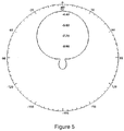
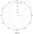
- FIGS 5 and 6 there are represented the irradiation diagrams of a cutlery article whose tang is not directly and electrically connected to a UHF RFID transponder with the reference OPP3613 of the company OPP IOT Technologies Co., Ltd and a irradiation diagram of an cutlery article whose tang is directly and electrically connected to a UHF RFID transponder with the reference OPP3613 of the company OPP IOT Technologies Co., Ltd, there being highlighted the huge increase of the irradiation when a tang is directly and electrically connected to a UHF RFID transponder.
Landscapes
- Engineering & Computer Science (AREA)
- Theoretical Computer Science (AREA)
- Computer Hardware Design (AREA)
- Microelectronics & Electronic Packaging (AREA)
- Physics & Mathematics (AREA)
- General Physics & Mathematics (AREA)
- Life Sciences & Earth Sciences (AREA)
- Forests & Forestry (AREA)
- Mechanical Engineering (AREA)
- Computer Networks & Wireless Communication (AREA)
- Table Equipment (AREA)
Abstract
Description
- The invention relates to a cutlery article which comprises a blade with a tang, a passive UHF identifier, which is connected to the tang, and a cable surrounding the tang and the passive UHF identifier.
- The cutlery article according to the invention may be tracked by an online tracking system, such as the tracking system developed by the applicant.
- In the treatment of food, particularly meat, the cleanliness and hygiene play a very important role. Typically, food are treated in contaminated environments. The contamination of food can cause considerable health damage to both the food processor and the consumer.
- The cutlery articles which are used in the treatment of food for human consumption must be regularly cleaned and sanitized to prevent both contamination of humans and contamination of food.
- In order to minimize the above mentioned problems, the applicant has developed a cutlery article with a passive UHF identifier, which allows its automatic control by means of an online system, which allows its control since its manufacture to its final recycling.
- Several problems were encountered during the implementation of the cutlery article such as, for instance, the placement of the passive identifier on its tang, the type of passive identifier to be used, its resistance to temperature and pressure, in order for it to be integrated into the production process of the cutlery article.
- The reliability of the control made online of a cutlery article from manufacture thereof to its final recycling and, more particularly, of the control of its regular cleaning, sanitation, sharpening, etc. can be performed through tracking and identification thereof by means of a system that includes UHF RFID readers.
- The reliability of the control of a cutlery article by means of a system that includes UHF RFID readers depends on the reliability of the reading performed of the passive identifier integrated in the cutlery article, by the UHF RFID readers. If the reading of a cutlery article, for instance, in a room or cleaning station is not reliable, the hygiene of the food cannot be ensured.
- The invention has for its object to provide a cutlery article with a passive identifier on its tang, the readability of which by a RFID UHF reader is increased and which solves or at least minimizes the problems mentioned above.
- This object is achieved by a cutlery article of the type mentioned in the beginning, which comprises a metallic blade, in particular of stainless steel, which extends through a tang, in which a passive identifier is arranged, which comprises two antennas arranged parallel in any flat surface of the tang suitable for the purpose.
- According to the invention the passive identifier is a UHF RFID transponder (ultra-high frequency in the range of 860 to 960 MHz) and one of its antennas is directly and electrically connected to said tang, said UHF RFID transponder belonging to the Iron Tag group. This frequency range allows the reading of the cutlery articles at a great distance (over than 1,5 m) and with great speed (around 294 m.s-1) and allows a quick response of the control system, that is, about 3 s.
- According to the invention, the blade of the cutlery article and its tang, which supports the passive UHF identifier, is integrated into a cutlery article handle, which integration is performed in order to be provided a very reliable reading of said UHF RFID transponder.
- According to the invention, an Iron Tag group UHF RFID transponder is used, as the UHF RFID transponders group have been specially designed for adverse environments, with extreme pressure and temperature, which confers to the UHF RFID transponders a very good resistance and durability to pressure and temperature of the plastic cable injection moulding process, the same being mounted on FR-4 PCB, fiberglass dielectric compound, since the UHF RFID transponder is implanted inside the handle as it is not admissible to change the mechanical, aesthetic and functional features of the cutlery articles.
- Since the blade of the cutlery article is metallic and electrically conductive it can, therefore, produce electrical currents induced upon the introduction of high frequency pulses into the blade by a UHF RFID reader. Similarly, the blade of the cutlery article can be used to maximize the irradiation of reflected and modelled pulses by the UHF RFID transponder.
- The invention provides, in its presently preferred embodiment, the electrical coupling of the antenna of the UHF RFID transponder to the tang due to the arrangement of, at least, a flat portion of one of its antennas parallel to any flat side surface suitable for the effect of the tang. In this way, the blade can be integrated directly into the antenna function of the UHF RFID transponder. In this case, between the antenna and the tang there is only one non-insulating ink layer, preferably from between 0,01 mm to 0,03 mm, more preferably of 0,02 mm. The connection of the UHF RFID transponder to the tang is made, preferably, by attachment through epoxy resins.
- The UHF RFID transponder is, according to the invention, passive and comprises two antennas, which provide the desired UHF RF communications. Thus, the placement of the UHF RFID transponder can be performed on either side of the tang, the behaviour being independent from the site of placement.
- According to the invention, a contact area between the UHF RFID transponder, that is, of one of the antennas, is preferably between 3 mm2 and 5 mm2, it being more preferably 4 mm2. These areas proved to be most suitable for large cutlery articles and for reading distances of about 1,5 m.
- A large area UHF RFID transponder has to be considered as its arrangement in small dimension cutlery articles (peeling knives) disordered in boxes implies that the RF pulses coming from the UHF RFID transponder have different orientations, it being necessary to obtain RF pulses with the biggest possible range.
- According to the invention, the optimal arrangement of the UHF RFID transponder, which has the straight parallelepiped shape, is the one closest to the outside, in order to exist a gap, preferably between 0,8 mm to 1,2 mm, more preferably of 1 mm between the UHF RFID transponder inserted into the handle, and the outer surface of the handle, so that the cutlery article is given the necessary mechanical properties and maintaining the bigger opposed face of the UHF RFID transponder in contact with the blade.
- The microchip of the UHF RFID transponder comprises a code that unambiguously identifies the cutlery article, the microchip also containing, however, further information, alternatively or additionally.
- There are described hereinafter embodiments of the invention which are only for illustrative purposes and not for limitation of the scope of the invention, the same being represented in the drawings. The drawings show in:
-
Figure 1 , a side and top schematic view of a cutlery article according to a first embodiment of the invention; -
Figure 2 , a top and side schematic view of a cutlery article according to a second embodiment of the invention; -
Figure 3 , top and side schematic views of a UHF RFID transponder used in the present invention, wherein it is highlighted its dimensions; -
Figure 4 , an exploded perspective schematic view of a UHF RFID transponder used in the embodiments according to the present invention; -
Figure 5 , an UHF RFID transponder irradiation diagram without metallic contact with the tang of the blade; -
Figure 6 , an UHF RFID transponder irradiation diagram used with metallic contact with the tang of the blade according to the present invention. -
Figure 1 shows a cutlery article according to a first embodiment of the invention, respectively, in a side view and a top view. The cutlery article comprises acutting blade 1, a tang 2, extending from thecutting blade 1, it being attached to the tang aUHF RFID transponder 10, and also anhandle 3, which surrounds a small portion of thecutting blade 1 and the set formed by the tang 2 and theUHF RFID transponder 10. Thepolypropylene cable 3 is made by an injection moulding process, so theUHF RFID transponder 10 must withstand the high pressure and temperature of this moulding process. In this figure it is highlighted that there must be a gap of 1 mm between a portion of the UHF RFID transponder and the environment. -
Figure 2 shows another cutlery article according to a second embodiment of the invention, which comprises a sharpening rifle 5 and a tang 4 extending from the sharpening rifle, with anUHF RFID transponder 10 being attached to the tang 4. The handle 3', as in the first embodiment, surrounds a small portion of the sharpening rifle 5 and the set formed by the tang 2 and theUHF RFID transponder 10, the cable 3' being of the same material and made by the same process as the cable of the first embodiment. In this figure it is also highlighted that there must be a gap of 1 mm between a portion of the UHF RFID transponder and the environment. -
Figure 3 shows schematically, in a top and side view, a UHF RFID transponder in the form of a straight parallelepiped, which is used in the present invention, where its dimensions are indicated. - Due to the fact that the
UHF RFID transponder 10 has to withstand the high pressure and temperature of the injection moulding process, theUHF RFID transponder 10 which has shown, during the tests performed to make the cutlery article, an improved performance with regard to the pressure and temperature resistance capabilities inherent to the injection moulding process and, at the same time, presents two antennas and a frequency range that allows for the reading of the cutlery articles at a great distance (greater than 1,5 m) and with great speed (294 m.s-1), was an ultra-high frequency UHF RFID transponder in the range of 860 to 960 MHz and the microchip of which belongs to the Iron Tag group which is commercially available under the OPP3613 reference of the OPP IOT Technologies Co., Ltd. -
Figure 5 schematically shows a perspective exploded view of the UHF RFID transponder, as mentioned above, which comprises two layers ofink equal antennas central core 13, which consists of FR4 (glass fiber composite dielectric material), which includes a PCB (printed circuit board), that is, a microchip. - Effectively, the fact that it comprises two antennas, one being directly and electrically connected to said tang, optimizes the performance of this UHF RFID transponder. Its frequency range allows the reading of the cutlery articles at a great distance (over than 1,5 m) and with great speed (294 m.s-1) and also allows a quick response from the control system, that is, about 3 s.
- In
Figures 5 and6 there are represented the irradiation diagrams of a cutlery article whose tang is not directly and electrically connected to a UHF RFID transponder with the reference OPP3613 of the company OPP IOT Technologies Co., Ltd and a irradiation diagram of an cutlery article whose tang is directly and electrically connected to a UHF RFID transponder with the reference OPP3613 of the company OPP IOT Technologies Co., Ltd, there being highlighted the huge increase of the irradiation when a tang is directly and electrically connected to a UHF RFID transponder.
Claims (5)
- Cutlery apparatus, which comprises a metallic blade (1) or a metallic rifle (5), in particular of stainless steel, extending through a tang (2 or 4), in which it is arranged a passive identifier (10), which comprises two antennas (12, 14), arranged parallel to each other and one being connected to any flat surface of the tang (2 or 4), and a cable (3 or 3'), which surrounds a small portion of the metallic blade (1) or of the metallic rifle (3) and surrounds completely the tang (2 or 4) and the passive identifier (10), characterized in that the passive identifier (10) is an UHF RFID transponder (ultra-high frequency in the range of 860 to 960 MHz), in that one of its antennas (12 or 14) is directly and electrically connected to said tang (2).
- Cutlery article according to claim 1, characterized in that the contact area between the passive identifier (10) is preferably between 3 mm2 and 5 mm2, being more preferably of 4 mm2.
- Cutlery article according to claim 1, characterized in that the connection between said passive identifier (10) and the tang is made by attachment through epoxy resins.
- Cutlery article according to claim 1, characterized in that the handle is made of plastic, preferably of polypropylene.
- Cutlery article according to claim 1, characterized in that there is a gap between said passive identifier (10), inserted into the handle (3 or 3') and the outer surface of said handle (3 or 3'), preferably between 0,8 mm and 1,2 mm, being more preferably of 1 mm.
Priority Applications (2)
| Application Number | Priority Date | Filing Date | Title |
|---|---|---|---|
| EP19398011.7A EP3809330B1 (en) | 2019-10-17 | 2019-10-17 | Cutlery article with a passive uhf identifier |
| PL19398011.7T PL3809330T3 (en) | 2019-10-17 | 2019-10-17 | Cutlery article with a passive uhf identifier |
Applications Claiming Priority (1)
| Application Number | Priority Date | Filing Date | Title |
|---|---|---|---|
| EP19398011.7A EP3809330B1 (en) | 2019-10-17 | 2019-10-17 | Cutlery article with a passive uhf identifier |
Publications (3)
| Publication Number | Publication Date |
|---|---|
| EP3809330A1 true EP3809330A1 (en) | 2021-04-21 |
| EP3809330C0 EP3809330C0 (en) | 2024-05-29 |
| EP3809330B1 EP3809330B1 (en) | 2024-05-29 |
Family
ID=68387250
Family Applications (1)
| Application Number | Title | Priority Date | Filing Date |
|---|---|---|---|
| EP19398011.7A Active EP3809330B1 (en) | 2019-10-17 | 2019-10-17 | Cutlery article with a passive uhf identifier |
Country Status (2)
| Country | Link |
|---|---|
| EP (1) | EP3809330B1 (en) |
| PL (1) | PL3809330T3 (en) |
Citations (4)
| Publication number | Priority date | Publication date | Assignee | Title |
|---|---|---|---|---|
| US20090121942A1 (en) * | 2006-02-28 | 2009-05-14 | Dong-Jin Lee | Rfid tag and ceramic patch antenna |
| WO2009146677A1 (en) * | 2008-06-04 | 2009-12-10 | ASTRA Gesellschaft für Asset Management mbH & Co. KG | Hand tool |
| US8269670B2 (en) * | 2007-10-12 | 2012-09-18 | Solstice Medical, Llc | Reusable, hermetic, medical grade RFID tag |
| US20160221198A1 (en) * | 2013-10-01 | 2016-08-04 | Friedr. Dick Gmbh & Co. Kg | Knife having an rfid transponder arranged on the tang |
-
2019
- 2019-10-17 PL PL19398011.7T patent/PL3809330T3/en unknown
- 2019-10-17 EP EP19398011.7A patent/EP3809330B1/en active Active
Patent Citations (4)
| Publication number | Priority date | Publication date | Assignee | Title |
|---|---|---|---|---|
| US20090121942A1 (en) * | 2006-02-28 | 2009-05-14 | Dong-Jin Lee | Rfid tag and ceramic patch antenna |
| US8269670B2 (en) * | 2007-10-12 | 2012-09-18 | Solstice Medical, Llc | Reusable, hermetic, medical grade RFID tag |
| WO2009146677A1 (en) * | 2008-06-04 | 2009-12-10 | ASTRA Gesellschaft für Asset Management mbH & Co. KG | Hand tool |
| US20160221198A1 (en) * | 2013-10-01 | 2016-08-04 | Friedr. Dick Gmbh & Co. Kg | Knife having an rfid transponder arranged on the tang |
Non-Patent Citations (1)
| Title |
|---|
| ANONYMOUS: "OPP IOT Focus on UHF RFID tags design and manufacture: 2017", 8 November 2017 (2017-11-08), XP055654224, Retrieved from the Internet <URL:http://oppiot.blogspot.com/2017/> [retrieved on 20191219] * |
Also Published As
| Publication number | Publication date |
|---|---|
| PL3809330T3 (en) | 2024-09-16 |
| EP3809330C0 (en) | 2024-05-29 |
| EP3809330B1 (en) | 2024-05-29 |
Similar Documents
| Publication | Publication Date | Title |
|---|---|---|
| US8624721B2 (en) | Method and apparatus for embedding a transmitter into a tool, and a system for monitoring the tool | |
| US8093996B2 (en) | Label incorporating a RF anti-theft antenna and an UHF RFID transponder | |
| EP3146479B1 (en) | Rfid tag assembly and surgical instrument | |
| US20190385037A1 (en) | Rfid tag | |
| EP2210219B1 (en) | Reusable, hermetic, medical grade rfid tag | |
| US9477922B2 (en) | UHF RFID wristband with a long read range | |
| US8807441B2 (en) | RFID tag antenna | |
| KR102589509B1 (en) | Dual-band transponder and textile label with dual-band transponder | |
| US20080129512A1 (en) | Method and apparatus for rfid reader/antenna | |
| US20080129513A1 (en) | Method and apparatus for rfid tags | |
| WO2010104991A2 (en) | Universal rfid tags and manufacturing methods | |
| US10335965B2 (en) | Knife having an RFID transponder arranged on the tang | |
| EP3271907A1 (en) | Temperature measurement system employing an electromagnetic transponder and separate impedance-changing parasitic antenna | |
| US8690068B2 (en) | Miniaturized UHF RFID tag for implantable medical device | |
| CN113544691B (en) | RF signal modulation via impedance variation | |
| US7546948B2 (en) | Identification device and method | |
| CN109447228B (en) | RFID electronic tag | |
| EP4372611A1 (en) | On-metal rfid tag | |
| EP3809330B1 (en) | Cutlery article with a passive uhf identifier | |
| US12579395B2 (en) | Tool having a detectable wireless marker or tag | |
| Azam et al. | Chipless RFID tag by V-shaped multi-resonator for partial discharge-affected equipment identification | |
| EP3555813A1 (en) | Long-range surface-insensitive passive rfid tag | |
| CN108027895B (en) | Method of manufacturing RFID tag assembly and RFID tag assembly | |
| CN201655969U (en) | Ultra-high frequency radio-frequency identification label antenna | |
| Pongpaibool | A study on performance of UHF RFID tags in a package for animal traceability application |
Legal Events
| Date | Code | Title | Description |
|---|---|---|---|
| PUAI | Public reference made under article 153(3) epc to a published international application that has entered the european phase |
Free format text: ORIGINAL CODE: 0009012 |
|
| STAA | Information on the status of an ep patent application or granted ep patent |
Free format text: STATUS: THE APPLICATION HAS BEEN PUBLISHED |
|
| AK | Designated contracting states |
Kind code of ref document: A1 Designated state(s): AL AT BE BG CH CY CZ DE DK EE ES FI FR GB GR HR HU IE IS IT LI LT LU LV MC MK MT NL NO PL PT RO RS SE SI SK SM TR |
|
| AX | Request for extension of the european patent |
Extension state: BA ME |
|
| STAA | Information on the status of an ep patent application or granted ep patent |
Free format text: STATUS: REQUEST FOR EXAMINATION WAS MADE |
|
| STAA | Information on the status of an ep patent application or granted ep patent |
Free format text: STATUS: EXAMINATION IS IN PROGRESS |
|
| 17P | Request for examination filed |
Effective date: 20211018 |
|
| RBV | Designated contracting states (corrected) |
Designated state(s): AL AT BE BG CH CY CZ DE DK EE ES FI FR GB GR HR HU IE IS IT LI LT LU LV MC MK MT NL NO PL PT RO RS SE SI SK SM TR |
|
| 17Q | First examination report despatched |
Effective date: 20211112 |
|
| GRAP | Despatch of communication of intention to grant a patent |
Free format text: ORIGINAL CODE: EPIDOSNIGR1 |
|
| STAA | Information on the status of an ep patent application or granted ep patent |
Free format text: STATUS: GRANT OF PATENT IS INTENDED |
|
| INTG | Intention to grant announced |
Effective date: 20240301 |
|
| GRAS | Grant fee paid |
Free format text: ORIGINAL CODE: EPIDOSNIGR3 |
|
| GRAA | (expected) grant |
Free format text: ORIGINAL CODE: 0009210 |
|
| STAA | Information on the status of an ep patent application or granted ep patent |
Free format text: STATUS: THE PATENT HAS BEEN GRANTED |
|
| AK | Designated contracting states |
Kind code of ref document: B1 Designated state(s): AL AT BE BG CH CY CZ DE DK EE ES FI FR GB GR HR HU IE IS IT LI LT LU LV MC MK MT NL NO PL PT RO RS SE SI SK SM TR |
|
| REG | Reference to a national code |
Ref country code: CH Ref legal event code: EP |
|
| REG | Reference to a national code |
Ref country code: IE Ref legal event code: FG4D |
|
| REG | Reference to a national code |
Ref country code: DE Ref legal event code: R096 Ref document number: 602019052872 Country of ref document: DE |
|
| U01 | Request for unitary effect filed |
Effective date: 20240531 |
|
| U07 | Unitary effect registered |
Designated state(s): AT BE BG DE DK EE FI FR IT LT LU LV MT NL PT SE SI Effective date: 20240610 |
|
| PG25 | Lapsed in a contracting state [announced via postgrant information from national office to epo] |
Ref country code: IS Free format text: LAPSE BECAUSE OF FAILURE TO SUBMIT A TRANSLATION OF THE DESCRIPTION OR TO PAY THE FEE WITHIN THE PRESCRIBED TIME-LIMIT Effective date: 20240929 |
|
| PG25 | Lapsed in a contracting state [announced via postgrant information from national office to epo] |
Ref country code: HR Free format text: LAPSE BECAUSE OF FAILURE TO SUBMIT A TRANSLATION OF THE DESCRIPTION OR TO PAY THE FEE WITHIN THE PRESCRIBED TIME-LIMIT Effective date: 20240529 |
|
| PG25 | Lapsed in a contracting state [announced via postgrant information from national office to epo] |
Ref country code: ES Free format text: LAPSE BECAUSE OF FAILURE TO SUBMIT A TRANSLATION OF THE DESCRIPTION OR TO PAY THE FEE WITHIN THE PRESCRIBED TIME-LIMIT Effective date: 20240529 |
|
| U20 | Renewal fee for the european patent with unitary effect paid |
Year of fee payment: 6 Effective date: 20240917 |
|
| PG25 | Lapsed in a contracting state [announced via postgrant information from national office to epo] |
Ref country code: NO Free format text: LAPSE BECAUSE OF FAILURE TO SUBMIT A TRANSLATION OF THE DESCRIPTION OR TO PAY THE FEE WITHIN THE PRESCRIBED TIME-LIMIT Effective date: 20240829 Ref country code: IS Free format text: LAPSE BECAUSE OF FAILURE TO SUBMIT A TRANSLATION OF THE DESCRIPTION OR TO PAY THE FEE WITHIN THE PRESCRIBED TIME-LIMIT Effective date: 20240929 Ref country code: HR Free format text: LAPSE BECAUSE OF FAILURE TO SUBMIT A TRANSLATION OF THE DESCRIPTION OR TO PAY THE FEE WITHIN THE PRESCRIBED TIME-LIMIT Effective date: 20240529 Ref country code: ES Free format text: LAPSE BECAUSE OF FAILURE TO SUBMIT A TRANSLATION OF THE DESCRIPTION OR TO PAY THE FEE WITHIN THE PRESCRIBED TIME-LIMIT Effective date: 20240529 Ref country code: RS Free format text: LAPSE BECAUSE OF FAILURE TO SUBMIT A TRANSLATION OF THE DESCRIPTION OR TO PAY THE FEE WITHIN THE PRESCRIBED TIME-LIMIT Effective date: 20240829 |
|
| PG25 | Lapsed in a contracting state [announced via postgrant information from national office to epo] |
Ref country code: CZ Free format text: LAPSE BECAUSE OF FAILURE TO SUBMIT A TRANSLATION OF THE DESCRIPTION OR TO PAY THE FEE WITHIN THE PRESCRIBED TIME-LIMIT Effective date: 20240529 |
|
| PG25 | Lapsed in a contracting state [announced via postgrant information from national office to epo] |
Ref country code: SK Free format text: LAPSE BECAUSE OF FAILURE TO SUBMIT A TRANSLATION OF THE DESCRIPTION OR TO PAY THE FEE WITHIN THE PRESCRIBED TIME-LIMIT Effective date: 20240529 Ref country code: RO Free format text: LAPSE BECAUSE OF FAILURE TO SUBMIT A TRANSLATION OF THE DESCRIPTION OR TO PAY THE FEE WITHIN THE PRESCRIBED TIME-LIMIT Effective date: 20240529 |
|
| PG25 | Lapsed in a contracting state [announced via postgrant information from national office to epo] |
Ref country code: SM Free format text: LAPSE BECAUSE OF FAILURE TO SUBMIT A TRANSLATION OF THE DESCRIPTION OR TO PAY THE FEE WITHIN THE PRESCRIBED TIME-LIMIT Effective date: 20240529 |
|
| PG25 | Lapsed in a contracting state [announced via postgrant information from national office to epo] |
Ref country code: SM Free format text: LAPSE BECAUSE OF FAILURE TO SUBMIT A TRANSLATION OF THE DESCRIPTION OR TO PAY THE FEE WITHIN THE PRESCRIBED TIME-LIMIT Effective date: 20240529 Ref country code: SK Free format text: LAPSE BECAUSE OF FAILURE TO SUBMIT A TRANSLATION OF THE DESCRIPTION OR TO PAY THE FEE WITHIN THE PRESCRIBED TIME-LIMIT Effective date: 20240529 Ref country code: RO Free format text: LAPSE BECAUSE OF FAILURE TO SUBMIT A TRANSLATION OF THE DESCRIPTION OR TO PAY THE FEE WITHIN THE PRESCRIBED TIME-LIMIT Effective date: 20240529 Ref country code: CZ Free format text: LAPSE BECAUSE OF FAILURE TO SUBMIT A TRANSLATION OF THE DESCRIPTION OR TO PAY THE FEE WITHIN THE PRESCRIBED TIME-LIMIT Effective date: 20240529 |
|
| PLBE | No opposition filed within time limit |
Free format text: ORIGINAL CODE: 0009261 |
|
| STAA | Information on the status of an ep patent application or granted ep patent |
Free format text: STATUS: NO OPPOSITION FILED WITHIN TIME LIMIT |
|
| 26N | No opposition filed |
Effective date: 20250303 |
|
| REG | Reference to a national code |
Ref country code: CH Ref legal event code: PL |
|
| PG25 | Lapsed in a contracting state [announced via postgrant information from national office to epo] |
Ref country code: MC Free format text: LAPSE BECAUSE OF FAILURE TO SUBMIT A TRANSLATION OF THE DESCRIPTION OR TO PAY THE FEE WITHIN THE PRESCRIBED TIME-LIMIT Effective date: 20240529 |
|
| PG25 | Lapsed in a contracting state [announced via postgrant information from national office to epo] |
Ref country code: CH Free format text: LAPSE BECAUSE OF NON-PAYMENT OF DUE FEES Effective date: 20241031 |
|
| U20 | Renewal fee for the european patent with unitary effect paid |
Year of fee payment: 7 Effective date: 20250807 |
|
| PGFP | Annual fee paid to national office [announced via postgrant information from national office to epo] |
Ref country code: PL Payment date: 20250718 Year of fee payment: 7 |
|
| PGFP | Annual fee paid to national office [announced via postgrant information from national office to epo] |
Ref country code: GB Payment date: 20250828 Year of fee payment: 7 |
|
| PG25 | Lapsed in a contracting state [announced via postgrant information from national office to epo] |
Ref country code: IE Free format text: LAPSE BECAUSE OF NON-PAYMENT OF DUE FEES Effective date: 20241017 |
|
| PG25 | Lapsed in a contracting state [announced via postgrant information from national office to epo] |
Ref country code: CY Free format text: LAPSE BECAUSE OF FAILURE TO SUBMIT A TRANSLATION OF THE DESCRIPTION OR TO PAY THE FEE WITHIN THE PRESCRIBED TIME-LIMIT; INVALID AB INITIO Effective date: 20191017 |
|
| PG25 | Lapsed in a contracting state [announced via postgrant information from national office to epo] |
Ref country code: HU Free format text: LAPSE BECAUSE OF FAILURE TO SUBMIT A TRANSLATION OF THE DESCRIPTION OR TO PAY THE FEE WITHIN THE PRESCRIBED TIME-LIMIT; INVALID AB INITIO Effective date: 20191017 |