EP3809252A1 - Sliding control method and apparatus, and household appliance - Google Patents
Sliding control method and apparatus, and household appliance Download PDFInfo
- Publication number
- EP3809252A1 EP3809252A1 EP18933412.1A EP18933412A EP3809252A1 EP 3809252 A1 EP3809252 A1 EP 3809252A1 EP 18933412 A EP18933412 A EP 18933412A EP 3809252 A1 EP3809252 A1 EP 3809252A1
- Authority
- EP
- European Patent Office
- Prior art keywords
- sliding
- sequence
- individual
- accordance
- phases
- Prior art date
- Legal status (The legal status is an assumption and is not a legal conclusion. Google has not performed a legal analysis and makes no representation as to the accuracy of the status listed.)
- Granted
Links
Images
Classifications
-
- G—PHYSICS
- G06—COMPUTING OR CALCULATING; COUNTING
- G06F—ELECTRIC DIGITAL DATA PROCESSING
- G06F3/00—Input arrangements for transferring data to be processed into a form capable of being handled by the computer; Output arrangements for transferring data from processing unit to output unit, e.g. interface arrangements
- G06F3/01—Input arrangements or combined input and output arrangements for interaction between user and computer
- G06F3/048—Interaction techniques based on graphical user interfaces [GUI]
- G06F3/0487—Interaction techniques based on graphical user interfaces [GUI] using specific features provided by the input device, e.g. functions controlled by the rotation of a mouse with dual sensing arrangements, or of the nature of the input device, e.g. tap gestures based on pressure sensed by a digitiser
- G06F3/0488—Interaction techniques based on graphical user interfaces [GUI] using specific features provided by the input device, e.g. functions controlled by the rotation of a mouse with dual sensing arrangements, or of the nature of the input device, e.g. tap gestures based on pressure sensed by a digitiser using a touch-screen or digitiser, e.g. input of commands through traced gestures
- G06F3/04883—Interaction techniques based on graphical user interfaces [GUI] using specific features provided by the input device, e.g. functions controlled by the rotation of a mouse with dual sensing arrangements, or of the nature of the input device, e.g. tap gestures based on pressure sensed by a digitiser using a touch-screen or digitiser, e.g. input of commands through traced gestures for inputting data by handwriting, e.g. gesture or text
-
- G—PHYSICS
- G06—COMPUTING OR CALCULATING; COUNTING
- G06F—ELECTRIC DIGITAL DATA PROCESSING
- G06F3/00—Input arrangements for transferring data to be processed into a form capable of being handled by the computer; Output arrangements for transferring data from processing unit to output unit, e.g. interface arrangements
- G06F3/01—Input arrangements or combined input and output arrangements for interaction between user and computer
- G06F3/048—Interaction techniques based on graphical user interfaces [GUI]
- G06F3/0484—Interaction techniques based on graphical user interfaces [GUI] for the control of specific functions or operations, e.g. selecting or manipulating an object, an image or a displayed text element, setting a parameter value or selecting a range
- G06F3/04847—Interaction techniques to control parameter settings, e.g. interaction with sliders or dials
-
- G—PHYSICS
- G06—COMPUTING OR CALCULATING; COUNTING
- G06F—ELECTRIC DIGITAL DATA PROCESSING
- G06F21/00—Security arrangements for protecting computers, components thereof, programs or data against unauthorised activity
- G06F21/30—Authentication, i.e. establishing the identity or authorisation of security principals
- G06F21/31—User authentication
- G06F21/36—User authentication by graphic or iconic representation
-
- G—PHYSICS
- G06—COMPUTING OR CALCULATING; COUNTING
- G06F—ELECTRIC DIGITAL DATA PROCESSING
- G06F3/00—Input arrangements for transferring data to be processed into a form capable of being handled by the computer; Output arrangements for transferring data from processing unit to output unit, e.g. interface arrangements
- G06F3/01—Input arrangements or combined input and output arrangements for interaction between user and computer
- G06F3/048—Interaction techniques based on graphical user interfaces [GUI]
- G06F3/0487—Interaction techniques based on graphical user interfaces [GUI] using specific features provided by the input device, e.g. functions controlled by the rotation of a mouse with dual sensing arrangements, or of the nature of the input device, e.g. tap gestures based on pressure sensed by a digitiser
- G06F3/0488—Interaction techniques based on graphical user interfaces [GUI] using specific features provided by the input device, e.g. functions controlled by the rotation of a mouse with dual sensing arrangements, or of the nature of the input device, e.g. tap gestures based on pressure sensed by a digitiser using a touch-screen or digitiser, e.g. input of commands through traced gestures
Definitions
- the present disclosure relates to the field of household appliances and electronic equipment, and in particular relates to a sliding control method and device, and a household appliance.
- the household appliance such as a washing machine is unlocked by means of combined keystrokes or sequential keystrokes.
- the present disclosure proposes a sliding control method and device, and a household appliance, so as to achieve determination of a control instruction corresponding to a sliding sequence, thereby providing an alternative method for controlling the household appliance or electronic equipment.
- the present method increases unlocking complexity, such that misoperation is avoided from occurring by accident, thereby improving reliability and safety of household appliance or electronic equipment. Therefore, the present method addresses the technique problem in the related art where the existing method for unlocking the household appliance is relative simple, which is prone to cause misoperation that decreases reliability and safety of household appliance.
- the present disclosure provides in embodiments a sliding control method, including: detecting a sliding touch control process; generating respective elements corresponding to individual sliding phases in accordance with respective positions to which individual sliding phases reach during the sliding touch control process; arranging the respective elements in accordance with an executing sequence of the individual sliding phases, thereby obtaining a sliding sequence; matching the sliding sequence to a control sequence preset; and executing a control instruction corresponding to the control sequence matched.
- the sliding control method detects a sliding touch control process; generates respective elements corresponding to individual sliding phases in accordance with respective positions to which individual sliding phases reach during the sliding touch control process; arranges the respective elements in accordance with an execution sequence of the individual sliding phases, thereby obtaining a sliding sequence; matches the sliding sequence to a control sequence preset; and executes a control instruction corresponding to the control sequence matched.
- the control instruction can be determined in accordance with the sliding sequence, thereby providing an alternative method for controlling the household appliance or electronic equipment.
- the present method increases unlocking complexity, such that misoperation is avoided from occurring by accident, thereby improving reliability and safety of household appliance or electronic equipment.
- a sliding control device including: a detecting module, configured to detect a sliding touch control process; a generating module, configured to generate respective elements corresponding to individual sliding phases in accordance with respective positions to which individual sliding phases reach during the sliding touch control process; an arranging module, configured to arrange the respective elements in accordance with an executing sequence of the individual sliding phases, thereby obtaining a sliding sequence; a matching module, configured to match the sliding sequence to a control sequence preset; and an executing module, configured to execute a control instruction corresponding to the control sequence matched.
- the sliding control device detects a sliding touch control process; generates respective elements corresponding to individual sliding phases in accordance with respective positions to which individual sliding phases reach during the sliding touch control process; arranges the respective elements in accordance with an execution sequence of the individual sliding phases, thereby obtaining a sliding sequence; matches the sliding sequence to a control sequence preset; and executes a control instruction corresponding to the control sequence matched.
- the control instruction can be determined in accordance with the sliding sequence, thereby providing an alternative device for controlling the household appliance or electronic equipment.
- the present device increases unlocking complexity, such that misoperation is avoided from occurring by accident, thereby improving reliability and safety of household appliance or electronic equipment.
- the present disclosure provides in embodiments a household appliance, including: a memory; a processor; and a computer program stored on the memory and executable by the processor, wherein the computer program, when executed by the processor, implements the sliding control method as described in the above embodiments of the present disclosure.
- the present disclosure provides in embodiments a computer readable storage medium having stored therein a computer program that, when executed by a processor, implements the sliding control method as described in the above embodiments of the present disclosure.
- the present disclosure proposes a sliding control method, which mainly addresses the technique problem in the related art where the existing method for unlocking household appliance is relative simple, which is prone to cause misoperation that decreases reliability and safety of the household appliance.
- the sliding control method detects a sliding touch control process; generates respective elements corresponding to individual sliding phases in accordance with respective positions to which individual sliding phases reach during the sliding touch control process; arranges the respective elements in accordance with an execution sequence of the individual sliding phases, thereby obtaining a sliding sequence; matches the sliding sequence to a control sequence preset; and executes a control instruction corresponding to the control sequence matched.
- the control instruction can be determined in accordance with the sliding sequence, thereby providing an alternative method for controlling the household appliance or electronic equipment.
- the present method increases unlocking complexity, such that misoperation is avoided from occurring by accident, thereby improving reliability and safety of household appliance or electronic equipment.
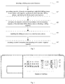
- Fig. 1 is a flow chart showing a sliding control method in an embodiment of the present disclosure.
- a sliding control method is exemplified with reference to configuration in a sliding control device.
- a sliding control device is applicable to a household appliance, like a washing machine, a household air conditioner, a refrigerator, a television and other smart appliances, or applicable to an electronic device, like a mobile phone, a tablet, a personal digital assistant, a wearable device, and other hardware devices with various operating systems, touch screens and/or displays, so that the household appliance or electronic device can implement a sliding control function.
- the sliding control method includes the following steps S101 to S105.
- Step 101 a sliding touch control process is detected.
- the sliding touch control process is a continuous process corresponding to a series of sliding touch control operations triggered by a user in a single time.
- a user may trigger a sliding touch control operation when unlocking a household appliance, issuing a control instruction or setting a functional parameter, and etc..
- the user may touch on a display screen to make a sliding touch control operation.
- the touched household appliance or electronic device may be provided with a monitor to monitor the sliding touch control operation from the user.
- the sliding touch control process can be monitored, that is, respective positions that individual sliding touch control operations pass by and coordinate values corresponding to the respective positions can be recorded.
- the sliding control method is exemplified with reference to application in a household appliance.
- the household appliance may be provided with a groove, which can accommodate a finger, at its control panel. Further, for convenience of user's operation, the groove may be of a width similar to the finger and provided with a sensor inside, which can be used to detect the sliding touch control process.
- the groove may be arranged horizontally or longitudinally, which is not limited herein.
- Fig. 2 is a schematic diagram showing a control panel of a washing machine in an embodiment of the present disclosure.
- the control panel is provided with the groove 21 for accommodating a finger
- the groove 21 is provided with a sensor at bottom by which the sliding touch control process can be detected, that is, respective positions that individual sliding touch operations pass by and coordinate values corresponding to the respective positions can be recorded by the sensor.
- the sliding touch control method is exemplified with reference to application in an electronic device.
- the electronic device is provided with a display screen, under which a sensor is also provided.
- a sliding touch control process can be detected by the sensor, that is, respective positions that individual sliding touch operations pass by and coordinate values corresponding to the respective positions can be recorded by the sensor.
- respective elements corresponding to individual sliding phases are generated in accordance with respective positions to which individual sliding phases reach during the sliding touch control process.
- each sliding phase corresponds to one element represented by a signed value.
- individual sliding phases during the sliding touch control process can be determined at first.
- individual sliding phases can be determined in accordance with a direction and amplitude of respective sliding touch control operations.
- individual sliding phases can be determined in accordance with a preset reference position, a duration that sliding stops at the preset reference position, changed or unchanged direction of two adjacent sliding, a duration that sliding stops at one position and/or a sliding stop position.
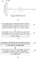
- Fig. 3 is a schematic diagram showing a sliding sequence in an embodiment of the present disclosure, where respective positions at the groove are of corresponding coordinate values, such that coordinate values of respective positions that individual sliding touch phases pass by can be recorded during the user's finger slides, and thus respective element values can be determined in accordance with respective positions to which individual sliding phases reach.
- the maximum coordinate values corresponding to respective positions that individual sliding phases pass by can be taken as the respective elements.
- the respective elements are arranged in accordance with an executing sequence of the individual sliding phases, thereby obtaining a sliding sequence.
- the respective elements can be arranged in accordance with an executing sequence of the individual sliding phases, thereby obtaining a sliding sequence.
- the first sliding phase corresponds to an element value of 1
- the second sliding phase corresponds to an element value of 1
- the third sliding phase corresponds to an element value of 2
- the ninth phase corresponds to an element value of 0.
- the sliding sequence can be obtained as "1, 0, 2, -2, 1, -3, 2, -2, 0".
- the sliding sequence is matched to a control sequence preset.
- control sequence is preset in advance, which is for example set as a default in a factory program of an electronic device or household appliance, or set by a user, which is not limited herein
- control sequence can be generated by triggering the sliding touch control operations as personally required by different users, thereby improving applicability of the present method.
- control sequence preset may be one or more control sequences, each of which corresponds to one control instruction.
- the sliding sequence is matched to a plurality of preset control sequence one by one. In the case that individual elements in the sliding sequence match with those in a certain control sequence and these elements in the sliding sequence are of an arranging order same as those in said control sequence, it is determined that the sliding sequence is matched with said control sequence.
- the matching result is not correct if the sliding sequence is determined to be matched with the control sequence.
- a control instruction corresponding to the control sequence matched is executed.
- control instruction may be different depending on different control sequences.
- control instruction corresponding to a control sequence A may be an unlocking instruction
- control instruction corresponding to a control sequence B may be a functional parameter setting instruction
- control instruction corresponding to a control sequence C may be a pause instruction
- control instruction corresponding to a control sequence D may be a stop instruction.
- a correspondence can be established between different control sequences and the control instructions in advance. Therefore, in an embodiment, after the sliding sequence is determined to be matched with the control sequence, an inquiry can be made in the correspondence by the control sequence, so as to acquire a corresponding control instruction. Accordingly, it is possible to control the electronic device or the household appliance to implement the corresponding control instruction.
- the sliding control method detects a sliding touch control process; generates respective elements corresponding to individual sliding phases in accordance with respective positions to which individual sliding phases reach during the sliding touch control process; arranges the respective elements in accordance with an execution sequence of the individual sliding phases, thereby obtaining a sliding sequence; matches the sliding sequence to a control sequence preset; and executes a control instruction corresponding to the control sequence matched.
- the control instruction can be determined in accordance with the sliding sequence, thereby providing an alternative method for controlling the household appliance or electronic equipment.
- the present method increases unlocking complexity, such that misoperation is avoided from occurring by accident, thereby improving reliability and safety of household appliance or electronic equipment.
- the preset control sequence can be updated.
- a user can set a control sequence in accordance with personalized needs and save this updated control sequence in a built-in program of the electronic device or household appliance. Further, verification can be made by requiring a user to input the control sequence again.
- the control sequence is updated only if a user inputs two identical control sequences, thereby preventing incorrect input from occurring.
- the sliding phase can be identified by the following step: sliding that starts from a preset reference position till returns to the preset reference position is identified as one sliding phase.
- the reference position is preset in advance, which is for example set as a default in a factory program of an electronic device or household appliance, or set by a user, which is not limited herein
- the sliding control method is exemplified with reference to application in the household appliance.
- the preset reference position may be either of two ends of the groove at the control panel.
- the preset reference position may be a position corresponding to the bottom end of the groove, or a position corresponding to the top end of the groove.
- the preset reference position may also be a symmetric center position, which is not limited herein
- the preset reference position is the position corresponding to the bottom end of the groove.
- a user's finger slides up from the preset reference position to a certain position, and then slides down from said certain position to the preset reference position, it is identified as one sliding phase.
- the user's finger may slide from the preset reference position again, and when the preset reference position is returned again, it is identified as another sliding phase.
- individual sliding phases can be determined.
- the preset duration is set in advance, which is for example set as a default in a factory program of an electronic device or household appliance, or set by a user, which is not limited herein
- the step 102 includes sub-steps 201 and 202.
- an absolute value of a corresponding element is determined in accordance with the maximum distance between individual positions that the current sliding phase passes by and the preset reference position.
- the preset reference position may be selected as an original position, and then respective distances between individual positions that the current sliding phase passes by and the preset reference position are determined based on a unit distance. From these determined distances, the maximum distance is selected as the absolute value of the corresponding element. Referring to Fig. 3 , when the groove is arranged longitudinally, it is assumed that the preset reference position is the symmetric center position of the groove, the maximum distance for the first sliding phase is "1"; the maximum distance for the second sliding phase is "0", and the maximum distance for the third sliding phase is "2", etc..
- a sign of the corresponding element is determined in accordance with a direction of a position with the maximum distance relative to the preset reference position.
- the groove when the sliding control method is applied in the household appliance, the groove is arranged longitudinally, and the preset reference position is the symmetric center position of the groove, the corresponding element may be determined to be of a positive value when the position with the maximum distance is above the preset reference position; while the corresponding element may be determined to be of a negative value when the position with the maximum distance is below the preset reference position.
- the corresponding element when the groove is arranged horizontally and the preset reference position is the symmetric center position of the groove, the corresponding element may be determined to be of a positive value when the position with the maximum distance is on the right of the preset reference position; while the corresponding element may be determined to be of a negative value when the position with the maximum distance is on the left of the preset reference position.
- the sign of the corresponding element can be determined, as practical requirement, in accordance with a direction of a position with the maximum distance relative to the preset reference position.
- the corresponding element may be determined to be of a positive value when the position with the maximum distance is below the preset reference position; or the corresponding element may be determined to be of a positive value when the position with the maximum distance is on the left of the preset reference position, which is not limited herein
- the element value may be "+1"; and for the fourth sliding phase, the position with the maximum distance is below the preset reference position, thus the element value may be "-2".
- the user's finger may start sliding from a certain start position instead of the preset reference position; and may change sliding direction when reach to another position and continue sliding.
- the sliding phase can be identified by the following step: two adjacent sliding direction changes are identified as one sliding phase.
- the step 102 may specifically include the following sub-steps 301 to 302.
- an absolute value of a corresponding element is determined in accordance with a distance between a start position and a stop position of each sliding phase.
- the stop position for the first sliding phase is a position where the sliding direction is changed firstly;
- the start position for the second sliding phase is the stop position for the first sliding phase and the stop position for the second sliding phase is a position where the sliding direction is changed secondly, and so on.
- a sign of the corresponding element is determined in accordance with a relative direction between the start position and the stop position of each sliding phase.
- the corresponding element when the sliding control method is applied in the household appliance and the groove is arranged longitudinally, the corresponding element may be determined to be of a positive value when the stop position is above the start position for each sliding phase; while the corresponding element may be determined to be of a negative value when the stop position is below the start position for each sliding phase.
- the corresponding element when the groove is arranged horizontally, the corresponding element may be determined to be of a positive value when the stop position is on the right of the start position for each sliding phase; while the corresponding element may be determined to be of a negative value when the stop position is on the left of the start position for each sliding phase.
- the sign of the corresponding element can be determined, as practical requirement, in accordance with a relative direction between the start position and the stop position of each sliding phase.
- the corresponding element may be determined to be of a positive value when the stop position is below the start position for each sliding phase; while the corresponding element may be determined to be of a positive value when the stop position is on the left of the start position for each sliding phase, which is not limited herein.
- the present disclosure further provides in embodiments a sliding control device.
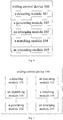
- Fig. 6 is a block diagram showing a sliding control device in still another embodiment of the present disclosure.
- the sliding control device 100 includes: a detecting module 101, a generating module 102, an arranging module 103, a matching module, 104 and an executing module 105.
- the detecting module 101 is configured to detect a sliding touch control process.
- the generating module 102 is configured to generate respective elements corresponding to individual sliding phases in accordance with respective positions to which individual sliding phases reach during the sliding touch control process.
- the arranging module 103 is configured to arrange the respective elements in accordance with an executing sequence of the individual sliding phases, thereby obtaining a sliding sequence.
- the matching module 104 is configured to match the sliding sequence to a control sequence preset.
- the executing module 105 is configured to execute a control instruction corresponding to the control sequence matched.
- the sliding control device 100 may further include an identify module 106.
- the identify module 106 is configured to identify sliding that starts from a preset reference position till returns to the preset reference position as one sliding phase; and identify sliding that stops at the preset reference position for a preset duration as one sliding phase, before respective elements corresponding to individual sliding phases are generated in accordance with respective positions to which individual sliding phases reach during the sliding touch control process.
- the identify module 106 is further configured to identify sliding that starts from a preset reference position till stops as one sliding phase.
- the generating module 102 is specifically configured: for each sliding phase, to determine an absolute value of a corresponding element in accordance with the maximum distance between individual positions that the current sliding phase passes by and the preset reference position; and if the absolute value is not zero, to determine a sign of the corresponding element in accordance with a direction of a position with the maximum distance relative to the preset reference position.
- the identify module 106 is further configured to identify two adjacent sliding direction changes as one sliding phase; and to identify sliding that stops at one position for a preset duration as one sliding phase.
- the generating module 102 is specifically configured to determine an absolute value of a corresponding element in accordance with a distance between a start position and a stop position of each sliding phase; and to determine a sign of the corresponding element in accordance with a relative direction between the start position and the stop position of each sliding phase if the absolute value is not zero.
- control instruction corresponding to the control sequence matched includes an unlocking instruction.
- the sliding control device detects a sliding touch control process; generates respective elements corresponding to individual sliding phases in accordance with respective positions to which individual sliding phases reach during the sliding touch control process; arranges the respective elements in accordance with an execution sequence of the individual sliding phases, thereby obtaining a sliding sequence; matches the sliding sequence to a control sequence preset; and executes a control instruction corresponding to the control sequence matched.
- the control instruction can be determined in accordance with the sliding sequence, thereby providing an alternative device for controlling the household appliance or electronic equipment.
- the present device increases unlocking complexity, such that misoperation is avoided from occurring by accident, thereby improving reliability and safety of household appliance or electronic equipment.
- the present disclosure provides in embodiments a household appliance, including a memory; a processor; and a computer program stored on the memory and executable by the processor, wherein the computer program, when executed by the processor, implements the sliding control method as described in the above embodiments of the present disclosure.
- the household appliance may be provided with a control panel, which is further provided with a groove for accommodating a finger.
- the groove is provided with a sensor at bottom by which the sliding touch control process can be detected.
- the groove may be arranged horizontally or longitudinally, which is not limited herein.
- the groove 21 can accommodate a finger and is provided with a sensor at bottom, so as to detect the sliding touch control process triggered by the user's finger.
- the present disclosure provides in embodiments a computer readable storage medium having stored therein a computer program that, when executed by a processor, implements the sliding control method as described in the above embodiments of the present disclosure.
- first and second are used herein for purposes of description and are not intended to indicate or imply relative importance or significance or impliedly indicate quantity of the technical feature referred to.
- the feature defined with “first” and “second” may comprise one or more this feature.
- a plurality of' means two or more than two this features, for example two, three and etc., unless specified otherwise.
- Any procedure or method described in the flow charts or described in any other way herein may be appreciated to comprise one or more modules, portions or parts for storing executable codes that realize particular logic functions or procedures.
- advantageous embodiments of the present disclosure comprises other implementations in which the order of execution is different from that which is depicted or discussed, including executing functions in a substantially simultaneous manner or in an opposite order according to the related functions. This should be appreciated by those skilled in the art to which embodiments of the present disclosure belong.
- the logic and/or step described in other manners herein or shown in the flow chart, for example, a particular sequence table of executable instructions for realizing the logical function may be specifically achieved in any computer readable medium to be used by the instruction execution system, device or equipment (such as the system based on computers, the system comprising processors or other systems capable of obtaining the instruction from the instruction execution system, device and equipment and executing the instruction), or to be used in combination with the instruction execution system, device and equipment.
- the computer readable medium may be any device adaptive for including, storing, communicating, propagating or transferring programs to be used by or in combination with the instruction execution system, device or equipment.
- the computer readable medium comprise but are not limited to: an electronic connection (an electronic device) with one or more wires, a portable computer enclosure (a magnetic device), a random access memory (RAM), a read only memory (ROM), an erasable programmable read-only memory (EPROM or a flash memory), an optical fiber device and a portable compact disk read-only memory (CDROM).
- the computer readable medium may even be a paper or other appropriate medium capable of printing programs thereon, this is because, for example, the paper or other appropriate medium may be optically scanned and then edited, decrypted or processed with other appropriate methods when necessary to obtain the programs in an electric manner, and then the programs may be stored in the computer memories.
- each part of the present disclosure may be realized by the hardware, software, firmware or their combination.
- a plurality of steps or methods may be realized by the software or firmware stored in the memory and executed by the appropriate instruction execution system.
- the steps or methods may be realized by one or a combination of the following techniques known in the art: a discrete logic circuit having a logic gate circuit for realizing a logic function of a data signal, an application-specific integrated circuit having an appropriate combination logic gate circuit, a programmable gate array (PGA), a field programmable gate array (FPGA), etc.
- each function cell of the embodiments of the present disclosure may be integrated in a processing module, or these cells may be separate physical existence, or two or more cells are integrated in a processing module.
- the integrated module may be realized in a form of hardware or in a form of software function modules. When the integrated module is realized in a form of software function module and is sold or used as a standalone product, the integrated module may be stored in a computer readable storage medium.
- the storage medium mentioned above may be read-only memories, magnetic disks, CD, etc.
Landscapes
- Engineering & Computer Science (AREA)
- Theoretical Computer Science (AREA)
- General Engineering & Computer Science (AREA)
- Physics & Mathematics (AREA)
- General Physics & Mathematics (AREA)
- Computer Security & Cryptography (AREA)
- Human Computer Interaction (AREA)
- Computer Hardware Design (AREA)
- Software Systems (AREA)
- Telephone Function (AREA)
- User Interface Of Digital Computer (AREA)
- Electronic Switches (AREA)
Abstract
Description
- This application claims a priority to Chinese Patent Application Serial No.
201811076518.8 - The present disclosure relates to the field of household appliances and electronic equipment, and in particular relates to a sliding control method and device, and a household appliance.
- With the continuous development of smart household appliance technology and the increasing popularity of household appliance, users can trigger a touch control operation on an operation interface of the household appliance to unlock, and then issue a control instruction to control the household appliance. In the related art, the household appliance such as a washing machine is unlocked by means of combined keystrokes or sequential keystrokes.
- The present disclosure proposes a sliding control method and device, and a household appliance, so as to achieve determination of a control instruction corresponding to a sliding sequence, thereby providing an alternative method for controlling the household appliance or electronic equipment. Besides, when the control instruction is to unlock, the present method increases unlocking complexity, such that misoperation is avoided from occurring by accident, thereby improving reliability and safety of household appliance or electronic equipment. Therefore, the present method addresses the technique problem in the related art where the existing method for unlocking the household appliance is relative simple, which is prone to cause misoperation that decreases reliability and safety of household appliance.
- In one aspect, the present disclosure provides in embodiments a sliding control method, including: detecting a sliding touch control process; generating respective elements corresponding to individual sliding phases in accordance with respective positions to which individual sliding phases reach during the sliding touch control process; arranging the respective elements in accordance with an executing sequence of the individual sliding phases, thereby obtaining a sliding sequence; matching the sliding sequence to a control sequence preset; and executing a control instruction corresponding to the control sequence matched.
- According to embodiments of the present disclosure, the sliding control method detects a sliding touch control process; generates respective elements corresponding to individual sliding phases in accordance with respective positions to which individual sliding phases reach during the sliding touch control process; arranges the respective elements in accordance with an execution sequence of the individual sliding phases, thereby obtaining a sliding sequence; matches the sliding sequence to a control sequence preset; and executes a control instruction corresponding to the control sequence matched. By this way, the control instruction can be determined in accordance with the sliding sequence, thereby providing an alternative method for controlling the household appliance or electronic equipment. Besides, when the control instruction is to unlock, the present method increases unlocking complexity, such that misoperation is avoided from occurring by accident, thereby improving reliability and safety of household appliance or electronic equipment.
- In another aspect, the present disclosure provides in embodiments a sliding control device, including: a detecting module, configured to detect a sliding touch control process; a generating module, configured to generate respective elements corresponding to individual sliding phases in accordance with respective positions to which individual sliding phases reach during the sliding touch control process; an arranging module, configured to arrange the respective elements in accordance with an executing sequence of the individual sliding phases, thereby obtaining a sliding sequence; a matching module, configured to match the sliding sequence to a control sequence preset; and an executing module, configured to execute a control instruction corresponding to the control sequence matched.
- According to embodiments of the present disclosure, the sliding control device detects a sliding touch control process; generates respective elements corresponding to individual sliding phases in accordance with respective positions to which individual sliding phases reach during the sliding touch control process; arranges the respective elements in accordance with an execution sequence of the individual sliding phases, thereby obtaining a sliding sequence; matches the sliding sequence to a control sequence preset; and executes a control instruction corresponding to the control sequence matched. By this way, the control instruction can be determined in accordance with the sliding sequence, thereby providing an alternative device for controlling the household appliance or electronic equipment. Besides, when the control instruction is to unlock, the present device increases unlocking complexity, such that misoperation is avoided from occurring by accident, thereby improving reliability and safety of household appliance or electronic equipment.
- In still another aspect, the present disclosure provides in embodiments a household appliance, including: a memory; a processor; and a computer program stored on the memory and executable by the processor, wherein the computer program, when executed by the processor, implements the sliding control method as described in the above embodiments of the present disclosure.
- In still another aspect, the present disclosure provides in embodiments a computer readable storage medium having stored therein a computer program that, when executed by a processor, implements the sliding control method as described in the above embodiments of the present disclosure.
- The additional aspects and advantages of the present disclosure will be partly given in the following description, and some will become obvious from the following description, or be learned through the practice of the present disclosure.
- In order to explain the technical solutions in the embodiments of the present disclosure more clearly, brief illustration will be made below with reference to the drawings involved in embodiments. Obviously, the drawings in the following description are merely some embodiments of the present disclosure, and it would be appreciated by those with ordinary skills in the art to obtain other drawings deriving from these shown drawings without creative efforts.
-
Fig. 1 is a flow chart showing a sliding control method in an embodiment of the present disclosure. -
Fig. 2 is a schematic diagram showing a control panel of a washing machine in an embodiment of the present disclosure. -
Fig. 3 is a schematic diagram showing a sliding sequence in an embodiment of the present disclosure. -
Fig. 4 is a flow chart showing a sliding control method in another embodiment of the present disclosure. -
Fig. 5 is a flow chart showing a sliding control method in still another embodiment of the present disclosure. -
Fig. 6 is a block diagram showing a sliding control device in still another embodiment of the present disclosure. -
Fig. 7 is a block diagram showing a sliding control device in still another embodiment of the present disclosure. - Reference will be made in detail to embodiments of the present disclosure. The same or similar elements and the elements having same or similar functions are denoted by like reference numerals throughout the descriptions. The embodiments described herein with reference to drawings are explanatory, illustrative, and used to generally understand the present disclosure. The embodiments shall not be construed to limit the present disclosure.
- The present disclosure proposes a sliding control method, which mainly addresses the technique problem in the related art where the existing method for unlocking household appliance is relative simple, which is prone to cause misoperation that decreases reliability and safety of the household appliance.
- According to embodiments of the present disclosure, the sliding control method detects a sliding touch control process; generates respective elements corresponding to individual sliding phases in accordance with respective positions to which individual sliding phases reach during the sliding touch control process; arranges the respective elements in accordance with an execution sequence of the individual sliding phases, thereby obtaining a sliding sequence; matches the sliding sequence to a control sequence preset; and executes a control instruction corresponding to the control sequence matched. By this way, the control instruction can be determined in accordance with the sliding sequence, thereby providing an alternative method for controlling the household appliance or electronic equipment. Besides, when the control instruction is to unlock, the present method increases unlocking complexity, such that misoperation is avoided from occurring by accident, thereby improving reliability and safety of household appliance or electronic equipment.
- The sliding control method and device, and household appliance in embodiments of present disclosure are described below with reference to the accompanying drawings.
-
Fig. 1 is a flow chart showing a sliding control method in an embodiment of the present disclosure. - In this embodiment, a sliding control method is exemplified with reference to configuration in a sliding control device. Such a sliding control device is applicable to a household appliance, like a washing machine, a household air conditioner, a refrigerator, a television and other smart appliances, or applicable to an electronic device, like a mobile phone, a tablet, a personal digital assistant, a wearable device, and other hardware devices with various operating systems, touch screens and/or displays, so that the household appliance or electronic device can implement a sliding control function.
- As shown in
Fig. 1 , the sliding control method includes the following steps S101 to S105. - At the
Step 101, a sliding touch control process is detected. - In an embodiment, the sliding touch control process is a continuous process corresponding to a series of sliding touch control operations triggered by a user in a single time.
- In an embodiment, a user may trigger a sliding touch control operation when unlocking a household appliance, issuing a control instruction or setting a functional parameter, and etc.. In specific, the user may touch on a display screen to make a sliding touch control operation. The touched household appliance or electronic device may be provided with a monitor to monitor the sliding touch control operation from the user. Once the sliding touch control operation is monitored from the user, the sliding touch control process can be monitored, that is, respective positions that individual sliding touch control operations pass by and coordinate values corresponding to the respective positions can be recorded.
- As an example, the sliding control method is exemplified with reference to application in a household appliance. The household appliance may be provided with a groove, which can accommodate a finger, at its control panel. Further, for convenience of user's operation, the groove may be of a width similar to the finger and provided with a sensor inside, which can be used to detect the sliding touch control process. The groove may be arranged horizontally or longitudinally, which is not limited herein.
- For example, the household appliance is a washing machine and a groove is arranged longitudinally. Referring to
Fig. 2, Fig. 2 is a schematic diagram showing a control panel of a washing machine in an embodiment of the present disclosure. As shown inFig. 2 , the control panel is provided with thegroove 21 for accommodating a finger, and thegroove 21 is provided with a sensor at bottom by which the sliding touch control process can be detected, that is, respective positions that individual sliding touch operations pass by and coordinate values corresponding to the respective positions can be recorded by the sensor. - As an example, the sliding touch control method is exemplified with reference to application in an electronic device. The electronic device is provided with a display screen, under which a sensor is also provided. When a user triggers a sliding touch control operation, a sliding touch control process can be detected by the sensor, that is, respective positions that individual sliding touch operations pass by and coordinate values corresponding to the respective positions can be recorded by the sensor.
- At the
step 102, respective elements corresponding to individual sliding phases are generated in accordance with respective positions to which individual sliding phases reach during the sliding touch control process. - In an embodiment, each sliding phase corresponds to one element represented by a signed value.
- In an embodiment, individual sliding phases during the sliding touch control process can be determined at first. For example, individual sliding phases can be determined in accordance with a direction and amplitude of respective sliding touch control operations. In specific, individual sliding phases can be determined in accordance with a preset reference position, a duration that sliding stops at the preset reference position, changed or unchanged direction of two adjacent sliding, a duration that sliding stops at one position and/or a sliding stop position. Detailed description will be made below, which is not elaborated herein
- In an embodiment, after individual sliding phases are determined, respective elements corresponding to individual sliding phases can be generated in accordance with respective positions to which individual sliding phases reach during the sliding touch control process. As an example, the sliding control method is exemplified with reference to application in a household appliance. Referring to
Fig. 3, Fig. 3 is a schematic diagram showing a sliding sequence in an embodiment of the present disclosure, where respective positions at the groove are of corresponding coordinate values, such that coordinate values of respective positions that individual sliding touch phases pass by can be recorded during the user's finger slides, and thus respective element values can be determined in accordance with respective positions to which individual sliding phases reach. For example, the maximum coordinate values corresponding to respective positions that individual sliding phases pass by can be taken as the respective elements. - At the
step 103, the respective elements are arranged in accordance with an executing sequence of the individual sliding phases, thereby obtaining a sliding sequence. - In an embodiment, once determined, the respective elements can be arranged in accordance with an executing sequence of the individual sliding phases, thereby obtaining a sliding sequence. Still taking the above example as shown in
Fig. 3 , the first sliding phase corresponds to an element value of 1, the second sliding phase corresponds to an element value of 0, the third sliding phase corresponds to an element value of 2, ..., the ninth phase corresponds to an element value of 0. As such, with arranging the respective elements in accordance with the executing sequence of the individual sliding phases, the sliding sequence can be obtained as "1, 0, 2, -2, 1, -3, 2, -2, 0". - At the
step 104, the sliding sequence is matched to a control sequence preset. - In an embodiment, the control sequence is preset in advance, which is for example set as a default in a factory program of an electronic device or household appliance, or set by a user, which is not limited herein For example, in order to meet different personalized setting needs, the control sequence can be generated by triggering the sliding touch control operations as personally required by different users, thereby improving applicability of the present method.
- It would be appreciated that the control sequence preset may be one or more control sequences, each of which corresponds to one control instruction. Thus, in the present disclosure, the sliding sequence is matched to a plurality of preset control sequence one by one. In the case that individual elements in the sliding sequence match with those in a certain control sequence and these elements in the sliding sequence are of an arranging order same as those in said control sequence, it is determined that the sliding sequence is matched with said control sequence.
- It should note that when the sliding sequence is "1, 0, 2, -2, 1" and the control sequence is "1, 0, 2, -2, 1, -3", the matching result is not correct if the sliding sequence is determined to be matched with the control sequence. Thus, in present disclosure, in order to improve accuracy of the matching result, it can be further determined whether the number of elements in the sliding sequence is consistent with that in the control sequence. If the number of elements in the sliding sequence is consistent with that in the control sequence, it is determined that the sliding sequence is matched with the control sequence; otherwise the sliding sequence is determined to be not matched with the control sequence.
- At the
step 105, a control instruction corresponding to the control sequence matched is executed. - In an embodiment, the control instruction may be different depending on different control sequences. For example, the control instruction corresponding to a control sequence A may be an unlocking instruction; the control instruction corresponding to a control sequence B may be a functional parameter setting instruction; the control instruction corresponding to a control sequence C may be a pause instruction; and the control instruction corresponding to a control sequence D may be a stop instruction.
- As a possible implementation, a correspondence can be established between different control sequences and the control instructions in advance. Therefore, in an embodiment, after the sliding sequence is determined to be matched with the control sequence, an inquiry can be made in the correspondence by the control sequence, so as to acquire a corresponding control instruction. Accordingly, it is possible to control the electronic device or the household appliance to implement the corresponding control instruction.
- According to embodiments of the present disclosure, the sliding control method detects a sliding touch control process; generates respective elements corresponding to individual sliding phases in accordance with respective positions to which individual sliding phases reach during the sliding touch control process; arranges the respective elements in accordance with an execution sequence of the individual sliding phases, thereby obtaining a sliding sequence; matches the sliding sequence to a control sequence preset; and executes a control instruction corresponding to the control sequence matched. By this way, the control instruction can be determined in accordance with the sliding sequence, thereby providing an alternative method for controlling the household appliance or electronic equipment. Besides, when the control instruction is to unlock, the present method increases unlocking complexity, such that misoperation is avoided from occurring by accident, thereby improving reliability and safety of household appliance or electronic equipment.
- As a possible implementation, in order to improve flexibility and applicability of the present method, the preset control sequence can be updated. A user can set a control sequence in accordance with personalized needs and save this updated control sequence in a built-in program of the electronic device or household appliance. Further, verification can be made by requiring a user to input the control sequence again. In specific, the control sequence is updated only if a user inputs two identical control sequences, thereby preventing incorrect input from occurring.
- As a possible implementation, the sliding phase can be identified by the following step: sliding that starts from a preset reference position till returns to the preset reference position is identified as one sliding phase.
- The reference position is preset in advance, which is for example set as a default in a factory program of an electronic device or household appliance, or set by a user, which is not limited herein
- As an example, the sliding control method is exemplified with reference to application in the household appliance. The preset reference position may be either of two ends of the groove at the control panel. For example, when the groove is arranged longitudinally, the preset reference position may be a position corresponding to the bottom end of the groove, or a position corresponding to the top end of the groove. Alternatively, the preset reference position may also be a symmetric center position, which is not limited herein
- As an example, when the groove is arranged longitudinally, it is assumed that the preset reference position is the position corresponding to the bottom end of the groove. When a user's finger slides up from the preset reference position to a certain position, and then slides down from said certain position to the preset reference position, it is identified as one sliding phase. Afterwards, the user's finger may slide from the preset reference position again, and when the preset reference position is returned again, it is identified as another sliding phase. As such, individual sliding phases can be determined.
- It should note that, during the sliding touch control process, if the user's finger stops at the preset reference position for a preset duration, it is identified as another sliding phase corresponding to an element value of 0. The preset duration is set in advance, which is for example set as a default in a factory program of an electronic device or household appliance, or set by a user, which is not limited herein
- It should note that, in the case that only one sliding phase exists in the sliding touch control process or the current sliding phase is the last sliding phase in the sliding touch control phase, the user's finger may move in only one direction without sliding to the preset reference position again, under this circumstance, such a sliding phase can be identified by the following step: sliding that starts from a preset reference position till stops is identified as one sliding phase.
- Accordingly, after individual sliding phases are determined, referring to
Fig.4 , thestep 102 includes sub-steps 201 and 202. - At the sub-step 201, for each sliding phase, an absolute value of a corresponding element is determined in accordance with the maximum distance between individual positions that the current sliding phase passes by and the preset reference position.
- For example, the preset reference position may be selected as an original position, and then respective distances between individual positions that the current sliding phase passes by and the preset reference position are determined based on a unit distance. From these determined distances, the maximum distance is selected as the absolute value of the corresponding element. Referring to
Fig. 3 , when the groove is arranged longitudinally, it is assumed that the preset reference position is the symmetric center position of the groove, the maximum distance for the first sliding phase is "1"; the maximum distance for the second sliding phase is "0", and the maximum distance for the third sliding phase is "2", etc.. - At the sub-step 202, if the absolute value is not zero, a sign of the corresponding element is determined in accordance with a direction of a position with the maximum distance relative to the preset reference position.
- As an example, when the sliding control method is applied in the household appliance, the groove is arranged longitudinally, and the preset reference position is the symmetric center position of the groove, the corresponding element may be determined to be of a positive value when the position with the maximum distance is above the preset reference position; while the corresponding element may be determined to be of a negative value when the position with the maximum distance is below the preset reference position. Alternatively, when the groove is arranged horizontally and the preset reference position is the symmetric center position of the groove, the corresponding element may be determined to be of a positive value when the position with the maximum distance is on the right of the preset reference position; while the corresponding element may be determined to be of a negative value when the position with the maximum distance is on the left of the preset reference position.
- It should note that the above examples are merely for illustration but cannot be construed as limitations to the present disclosure. In practical applications, the sign of the corresponding element can be determined, as practical requirement, in accordance with a direction of a position with the maximum distance relative to the preset reference position. For example, the corresponding element may be determined to be of a positive value when the position with the maximum distance is below the preset reference position; or the corresponding element may be determined to be of a positive value when the position with the maximum distance is on the left of the preset reference position, which is not limited herein
- As an example, referring to
Fig. 3 , for the first sliding phase, the position with the maximum distance is above the preset reference position, thus the element value may be "+1"; and for the fourth sliding phase, the position with the maximum distance is below the preset reference position, thus the element value may be "-2". - As an alternative possible implementation, during the sliding touch control process, the user's finger may start sliding from a certain start position instead of the preset reference position; and may change sliding direction when reach to another position and continue sliding. Thus, in the present disclosure, the sliding phase can be identified by the following step: two adjacent sliding direction changes are identified as one sliding phase.
- It should note that, during the sliding touch control process, if the user's finger stops at one position for a preset duration, it is identified as another sliding phase corresponding to an element value of 0.
- Accordingly, after individual sliding phases are determined, referring to
Fig. 5 , thestep 102 may specifically include the followingsub-steps 301 to 302. - At the sub-step 301, an absolute value of a corresponding element is determined in accordance with a distance between a start position and a stop position of each sliding phase.
- In an embodiment, it is assumed that the user's finger does not stop at one position for a preset duration during the sliding touch control process, then the stop position for the first sliding phase is a position where the sliding direction is changed firstly; the start position for the second sliding phase is the stop position for the first sliding phase and the stop position for the second sliding phase is a position where the sliding direction is changed secondly, and so on. As such, respective start positions and stop positions of individual sliding phases can be obtained, and thus the absolute value of the corresponding element can be determined in accordance with the distance between the start position and the stop position of each sliding phase.
- During the sliding touch control process, if the user's finger stops at one position for a preset duration, it is identified as another sliding phase corresponding to an element value of 0.
- At the sub-step 302, if the absolute value is not zero, a sign of the corresponding element is determined in accordance with a relative direction between the start position and the stop position of each sliding phase.
- As an example, when the sliding control method is applied in the household appliance and the groove is arranged longitudinally, the corresponding element may be determined to be of a positive value when the stop position is above the start position for each sliding phase; while the corresponding element may be determined to be of a negative value when the stop position is below the start position for each sliding phase. As an alternative example, when the groove is arranged horizontally, the corresponding element may be determined to be of a positive value when the stop position is on the right of the start position for each sliding phase; while the corresponding element may be determined to be of a negative value when the stop position is on the left of the start position for each sliding phase.
- It should note that the above examples are merely for illustration but cannot be construed as limitations to the present disclosure. In practical applications, the sign of the corresponding element can be determined, as practical requirement, in accordance with a relative direction between the start position and the stop position of each sliding phase. For example, the corresponding element may be determined to be of a positive value when the stop position is below the start position for each sliding phase; while the corresponding element may be determined to be of a positive value when the stop position is on the left of the start position for each sliding phase, which is not limited herein.
- In order to achieve the above examples, the present disclosure further provides in embodiments a sliding control device.
-
Fig. 6 is a block diagram showing a sliding control device in still another embodiment of the present disclosure. - As shown in
Fig. 6 , the slidingcontrol device 100 includes: a detectingmodule 101, agenerating module 102, an arrangingmodule 103, a matching module, 104 and an executingmodule 105. - The detecting
module 101 is configured to detect a sliding touch control process. - The
generating module 102 is configured to generate respective elements corresponding to individual sliding phases in accordance with respective positions to which individual sliding phases reach during the sliding touch control process. - The arranging
module 103 is configured to arrange the respective elements in accordance with an executing sequence of the individual sliding phases, thereby obtaining a sliding sequence. - The
matching module 104 is configured to match the sliding sequence to a control sequence preset. - The executing
module 105 is configured to execute a control instruction corresponding to the control sequence matched. - Further, the present disclosure provides in embodiments a possible implementation, referring to
Fig. 7 , which is on the basis of embodiment as shown inFig. 6 , the slidingcontrol device 100 may further include anidentify module 106. - The
identify module 106 is configured to identify sliding that starts from a preset reference position till returns to the preset reference position as one sliding phase; and identify sliding that stops at the preset reference position for a preset duration as one sliding phase, before respective elements corresponding to individual sliding phases are generated in accordance with respective positions to which individual sliding phases reach during the sliding touch control process. - As a possible implementation, the
identify module 106 is further configured to identify sliding that starts from a preset reference position till stops as one sliding phase. - Accordingly, the
generating module 102 is specifically configured: for each sliding phase, to determine an absolute value of a corresponding element in accordance with the maximum distance between individual positions that the current sliding phase passes by and the preset reference position; and if the absolute value is not zero, to determine a sign of the corresponding element in accordance with a direction of a position with the maximum distance relative to the preset reference position. - As an alternative possible implementation, the
identify module 106 is further configured to identify two adjacent sliding direction changes as one sliding phase; and to identify sliding that stops at one position for a preset duration as one sliding phase. - Accordingly, the
generating module 102 is specifically configured to determine an absolute value of a corresponding element in accordance with a distance between a start position and a stop position of each sliding phase; and to determine a sign of the corresponding element in accordance with a relative direction between the start position and the stop position of each sliding phase if the absolute value is not zero. - As a possible implementation, the control instruction corresponding to the control sequence matched includes an unlocking instruction.
- It should note that the foregoing explanation in embodiments as to the sliding control method is also applicable to the sliding
control device 100 in the embodiments, which is not repeated herein - According to embodiments of the present disclosure, the sliding control device detects a sliding touch control process; generates respective elements corresponding to individual sliding phases in accordance with respective positions to which individual sliding phases reach during the sliding touch control process; arranges the respective elements in accordance with an execution sequence of the individual sliding phases, thereby obtaining a sliding sequence; matches the sliding sequence to a control sequence preset; and executes a control instruction corresponding to the control sequence matched. By this way, the control instruction can be determined in accordance with the sliding sequence, thereby providing an alternative device for controlling the household appliance or electronic equipment. Besides, when the control instruction is to unlock, the present device increases unlocking complexity, such that misoperation is avoided from occurring by accident, thereby improving reliability and safety of household appliance or electronic equipment.
- In order to achieve the above embodiments, the present disclosure provides in embodiments a household appliance, including a memory; a processor; and a computer program stored on the memory and executable by the processor, wherein the computer program, when executed by the processor, implements the sliding control method as described in the above embodiments of the present disclosure.
- Further, the household appliance may be provided with a control panel, which is further provided with a groove for accommodating a finger.
- The groove is provided with a sensor at bottom by which the sliding touch control process can be detected.
- In an embodiment, the groove may be arranged horizontally or longitudinally, which is not limited herein.
- As an example, when the household appliance is a washing machine and the groove is arranged longitudinally, referring to
Fig. 2 , thegroove 21 can accommodate a finger and is provided with a sensor at bottom, so as to detect the sliding touch control process triggered by the user's finger. - It should note that the foregoing explanation in embodiments as to the sliding control method is also applicable to the household appliance in this embodiment, which is not repeated herein.
- In order to achieve the above embodiments, the present disclosure provides in embodiments a computer readable storage medium having stored therein a computer program that, when executed by a processor, implements the sliding control method as described in the above embodiments of the present disclosure.
- Reference throughout this specification to "an embodiment", "some embodiments", "one embodiment", "another example", "an example", "a specific example" or "some examples" means that a particular feature, structure, material, or characteristic described in connection with the embodiment or example is included in at least one embodiment or example of the present disclosure. Thus, the appearances of the phrases such as "in some embodiments", "in one embodiment", "in an embodiment", "in another example", "in an example", "in a specific example" or "in some examples", in various places throughout this specification are not necessarily referring to the same embodiment or example of the present disclosure. Furthermore, the particular features, structures, materials, or characteristics may be combined in any suitable manner in one or more embodiments or examples. In addition, those skilled in the art can combine the different embodiments or examples and the features described in the different embodiments or examples in this specification without contradicting each other.
- In addition, terms such as "first" and "second" are used herein for purposes of description and are not intended to indicate or imply relative importance or significance or impliedly indicate quantity of the technical feature referred to. Thus, the feature defined with "first" and "second" may comprise one or more this feature. In the description of the present disclosure, "a plurality of' means two or more than two this features, for example two, three and etc., unless specified otherwise.
- Any procedure or method described in the flow charts or described in any other way herein may be appreciated to comprise one or more modules, portions or parts for storing executable codes that realize particular logic functions or procedures. Moreover, advantageous embodiments of the present disclosure comprises other implementations in which the order of execution is different from that which is depicted or discussed, including executing functions in a substantially simultaneous manner or in an opposite order according to the related functions. This should be appreciated by those skilled in the art to which embodiments of the present disclosure belong.
- The logic and/or step described in other manners herein or shown in the flow chart, for example, a particular sequence table of executable instructions for realizing the logical function, may be specifically achieved in any computer readable medium to be used by the instruction execution system, device or equipment (such as the system based on computers, the system comprising processors or other systems capable of obtaining the instruction from the instruction execution system, device and equipment and executing the instruction), or to be used in combination with the instruction execution system, device and equipment. As to the specification, "the computer readable medium" may be any device adaptive for including, storing, communicating, propagating or transferring programs to be used by or in combination with the instruction execution system, device or equipment. More specific examples of the computer readable medium comprise but are not limited to: an electronic connection (an electronic device) with one or more wires, a portable computer enclosure (a magnetic device), a random access memory (RAM), a read only memory (ROM), an erasable programmable read-only memory (EPROM or a flash memory), an optical fiber device and a portable compact disk read-only memory (CDROM). In addition, the computer readable medium may even be a paper or other appropriate medium capable of printing programs thereon, this is because, for example, the paper or other appropriate medium may be optically scanned and then edited, decrypted or processed with other appropriate methods when necessary to obtain the programs in an electric manner, and then the programs may be stored in the computer memories.
- It should be appreciated that each part of the present disclosure may be realized by the hardware, software, firmware or their combination. In the above embodiments, a plurality of steps or methods may be realized by the software or firmware stored in the memory and executed by the appropriate instruction execution system. For example, if it is realized by the hardware, likewise in another embodiment, the steps or methods may be realized by one or a combination of the following techniques known in the art: a discrete logic circuit having a logic gate circuit for realizing a logic function of a data signal, an application-specific integrated circuit having an appropriate combination logic gate circuit, a programmable gate array (PGA), a field programmable gate array (FPGA), etc.
- Those skilled in the art shall appreciate that all or parts of the steps in the above exemplifying method for the present disclosure may be achieved by commanding the related hardware with programs. The programs may be stored in a computer readable storage medium, and the programs comprise one or a combination of the steps in the method embodiments of the present disclosure when run on a computer.
- In addition, each function cell of the embodiments of the present disclosure may be integrated in a processing module, or these cells may be separate physical existence, or two or more cells are integrated in a processing module. The integrated module may be realized in a form of hardware or in a form of software function modules. When the integrated module is realized in a form of software function module and is sold or used as a standalone product, the integrated module may be stored in a computer readable storage medium.
- The storage medium mentioned above may be read-only memories, magnetic disks, CD, etc.
- Although explanatory embodiments have been shown and described, it would be appreciated by those skilled in the art that the above embodiments cannot be construed to limit the present disclosure, and changes, alternatives, and modifications can be made in the embodiments in the scope of the present disclosure.
Claims (11)
- A sliding control method, comprising:detecting a sliding touch control process;generating respective elements corresponding to individual sliding phases in accordance with respective positions to which individual sliding phases reach during the sliding touch control process;arranging the respective elements in accordance with an executing sequence of the individual sliding phases, thereby obtaining a sliding sequence;matching the sliding sequence to a control sequence preset; andexecuting a control instruction corresponding to the control sequence matched.
- The sliding control method according to claim 1, further comprising, prior to generating respective elements corresponding to individual sliding phases in accordance with respective positions to which individual sliding phases reach during the sliding touch control process:identifying sliding that starts from a preset reference position till returns to the preset reference position as one sliding phase; andidentifying sliding that stops at the preset reference position for a preset duration as one sliding phase.
- The sliding control method according to claim 1 or 2, further comprising, prior to generating respective elements corresponding to individual sliding phases in accordance with respective positions to which individual sliding phases reach during the sliding touch control process:
identifying sliding that starts from a preset reference position till stops as one sliding phase. - The sliding control method according to claim 2 or 3, wherein generating respective elements corresponding to individual sliding phases in accordance with respective positions to which individual sliding phases reach during the sliding touch control process further comprises:for each sliding phase, determining an absolute value of a corresponding element in accordance with the maximum distance between individual positions that a current sliding phase passes by and the preset reference position; andif the absolute value is not zero, determining a sign of the corresponding element in accordance with a direction of a position with the maximum distance relative to the preset reference position.
- The sliding control method according to any one of claims 1 to 4, further comprising, prior to generating respective elements corresponding to individual sliding phases in accordance with respective positions to which individual sliding phases reach during the sliding touch control process:identifying a sliding touch control process between two adjacent sliding directions changes as one sliding phase; andidentifying sliding that stops at one position for a preset duration as one sliding phase.
- The sliding control method according to any one of claims 1 to 5, wherein generating respective elements corresponding to individual sliding phases in accordance with respective positions to which individual sliding phases reach during the sliding touch control process further comprises:determining an absolute value of a corresponding element in accordance with a distance between a start position and a stop position of each sliding phase, anddetermining a sign of the corresponding element in accordance with a relative direction between the start position and the stop position of each sliding phase if the absolute value is not zero.
- The sliding control method according to any one of claims 1 to 6, wherein the control instruction corresponding to the control sequence matched comprises an unlocking instruction.
- A sliding control device, comprising:a detecting module, configured to detect a sliding touch control process;a generating module, configured to generate respective elements corresponding to individual sliding phases in accordance with respective positions to which individual sliding phases reach during the sliding touch control process;an arranging module, configured to arrange the respective elements in accordance with an executing sequence of the individual sliding phases, thereby obtaining a sliding sequence;a matching module, configured to match the sliding sequence to a control sequence preset; andan executing module, configured to execute a control instruction corresponding to the control sequence matched.
- A household appliance, comprising:a memory;a processor; anda computer program stored on the memory and executable by the processor, wherein the computer program, when executed by the processor, implements the sliding control method as defined in any one of claims 1 to 7.
- The household appliance according to claim 9, wherein
the household appliance is provided with a control panel,
the control panel is provided with a groove for accommodating a finger, and
the groove is a provided with a sensor at bottom and configured to detect the sliding touch control process. - A computer readable storage medium having stored therein a computer program that, when executed by a processor, implements the sliding control method as defined in any one of claims 1 to 7.
Applications Claiming Priority (2)
| Application Number | Priority Date | Filing Date | Title |
|---|---|---|---|
| CN201811076518.8A CN109284061A (en) | 2018-09-14 | 2018-09-14 | Slide control method, device and home appliance |
| PCT/CN2018/114339 WO2020052036A1 (en) | 2018-09-14 | 2018-11-07 | Sliding control method and apparatus, and household appliance |
Publications (3)
| Publication Number | Publication Date |
|---|---|
| EP3809252A1 true EP3809252A1 (en) | 2021-04-21 |
| EP3809252A4 EP3809252A4 (en) | 2021-08-11 |
| EP3809252B1 EP3809252B1 (en) | 2025-06-25 |
Family
ID=65180723
Family Applications (1)
| Application Number | Title | Priority Date | Filing Date |
|---|---|---|---|
| EP18933412.1A Active EP3809252B1 (en) | 2018-09-14 | 2018-11-07 | Sliding control method and apparatus, and household appliance |
Country Status (3)
| Country | Link |
|---|---|
| EP (1) | EP3809252B1 (en) |
| CN (1) | CN109284061A (en) |
| WO (1) | WO2020052036A1 (en) |
Family Cites Families (16)
| Publication number | Priority date | Publication date | Assignee | Title |
|---|---|---|---|---|
| US9614671B2 (en) * | 2011-12-02 | 2017-04-04 | Barclays Bank Plc | User access control based on a graphical signature |
| KR101497762B1 (en) * | 2012-02-01 | 2015-03-05 | 서울시립대학교 산학협력단 | Unlocking method, and terminal and recording medium for the same method |
| CN202523049U (en) * | 2012-04-18 | 2012-11-07 | 珠海格力电器股份有限公司 | Control device and household electrical appliance |
| CN103678998B (en) * | 2012-09-20 | 2016-08-31 | 昆达电脑科技(昆山)有限公司 | The password forming method of electronic installation and system |
| CN202836055U (en) * | 2012-10-22 | 2013-03-27 | 海尔集团公司 | Sliding touch control device and refrigerator with the same |
| TW201426400A (en) * | 2012-12-26 | 2014-07-01 | Hon Hai Prec Ind Co Ltd | Electronic device and quickly sending email method thereof method and system for unlocking screen |
| CN103092523A (en) * | 2013-01-29 | 2013-05-08 | 北京小米科技有限责任公司 | Unlocking method and terminal |
| US20150121315A1 (en) * | 2013-10-27 | 2015-04-30 | David Michael Glenn | Gesture based method for entering multi-variable data on a graphical user interface. |
| CN104834441B (en) * | 2014-02-11 | 2018-07-31 | 联想企业解决方案(新加坡)有限公司 | Method and device for unlocking touch screen |
| CN104536686A (en) * | 2014-12-23 | 2015-04-22 | 北京元心科技有限公司 | Screen unlocking method and device |
| CN105426736A (en) * | 2015-10-30 | 2016-03-23 | 无锡天脉聚源传媒科技有限公司 | Password setting method and apparatus |
| JP2018022266A (en) * | 2016-08-02 | 2018-02-08 | 株式会社デンソーウェーブ | Security device |
| CN106295308B (en) * | 2016-08-22 | 2019-01-04 | 维沃移动通信有限公司 | A kind of unlocking method and mobile terminal of application program for mobile terminal |
| CN107422973B (en) * | 2017-07-10 | 2021-02-26 | 广州视源电子科技股份有限公司 | Control device and control method |
| CN108227525B (en) * | 2017-12-04 | 2020-10-23 | 无锡小天鹅电器有限公司 | Control method and device of household appliance and washing machine |
| CN108376050A (en) * | 2018-02-24 | 2018-08-07 | 海信(山东)空调有限公司 | Household electrical appliance and its control method and control assembly |
-
2018
- 2018-09-14 CN CN201811076518.8A patent/CN109284061A/en active Pending
- 2018-11-07 EP EP18933412.1A patent/EP3809252B1/en active Active
- 2018-11-07 WO PCT/CN2018/114339 patent/WO2020052036A1/en not_active Ceased
Also Published As
| Publication number | Publication date |
|---|---|
| CN109284061A (en) | 2019-01-29 |
| WO2020052036A1 (en) | 2020-03-19 |
| EP3809252B1 (en) | 2025-06-25 |
| EP3809252A4 (en) | 2021-08-11 |
Similar Documents
| Publication | Publication Date | Title |
|---|---|---|
| CN103092503B (en) | The unblock of mobile terminal and verification method and unblock and checking device | |
| KR102345911B1 (en) | Virtual input apparatus and method for receiving user input using thereof | |
| US10734997B2 (en) | Touch and force sensitive rocker switch | |
| US20110246952A1 (en) | Electronic device capable of defining touch gestures and method thereof | |
| US20140173498A1 (en) | Multiple screen mode in mobile terminal | |
| EP4224301A1 (en) | Payment interface display method and apparatus, and electronic device | |
| JP5728629B2 (en) | Information processing apparatus, information processing apparatus control method, program, and information storage medium | |
| KR20170102423A (en) | Information processing apparatus, information processing method and storage medium | |
| CN106250190A (en) | A kind of application startup method and terminal | |
| CN107370874B (en) | Application starting method, mobile terminal and storage medium | |
| US20150199058A1 (en) | Information processing method and electronic device | |
| CN104932828A (en) | Information processing method and electronic equipment | |
| CN107943401A (en) | A kind of function triggering method and device, computer installation, readable storage medium storing program for executing | |
| CN110088719B (en) | Display method of mobile equipment and mobile equipment | |
| EP3508966A1 (en) | Household appliance control method and device, and washing machine | |
| US10423249B2 (en) | Information processing method and electronic device | |
| WO2017202077A1 (en) | Mobile terminal control method and apparatus and mobile terminal | |
| CN108683809B (en) | Screen locking method, device and system | |
| EP3809252B1 (en) | Sliding control method and apparatus, and household appliance | |
| EP3579142A1 (en) | Verification method, verification device, electronic device and computer readable storage medium | |
| CN105824534A (en) | Information processing method and electronic equipment | |
| CN104484095A (en) | Information processing method and electronic device | |
| CN103699232A (en) | Command input method and device | |
| WO2020108491A1 (en) | Method for opening application, application opening device, electronic apparatus, and computer readable storage medium | |
| CN104007916B (en) | A kind of information processing method and electronic equipment |
Legal Events
| Date | Code | Title | Description |
|---|---|---|---|
| STAA | Information on the status of an ep patent application or granted ep patent |
Free format text: STATUS: THE INTERNATIONAL PUBLICATION HAS BEEN MADE |
|
| PUAI | Public reference made under article 153(3) epc to a published international application that has entered the european phase |
Free format text: ORIGINAL CODE: 0009012 |
|
| STAA | Information on the status of an ep patent application or granted ep patent |
Free format text: STATUS: REQUEST FOR EXAMINATION WAS MADE |
|
| 17P | Request for examination filed |
Effective date: 20210113 |
|
| AK | Designated contracting states |
Kind code of ref document: A1 Designated state(s): AL AT BE BG CH CY CZ DE DK EE ES FI FR GB GR HR HU IE IS IT LI LT LU LV MC MK MT NL NO PL PT RO RS SE SI SK SM TR |
|
| AX | Request for extension of the european patent |
Extension state: BA ME |
|
| REG | Reference to a national code |
Ref country code: DE Free format text: PREVIOUS MAIN CLASS: G06F0003048800 Ref country code: DE Ref legal event code: R079 Ref document number: 602018083061 Country of ref document: DE Free format text: PREVIOUS MAIN CLASS: G06F0003048800 Ipc: G06F0003048400 |
|
| A4 | Supplementary search report drawn up and despatched |
Effective date: 20210708 |
|
| RIC1 | Information provided on ipc code assigned before grant |
Ipc: G06F 3/0484 20130101AFI20210702BHEP Ipc: G06F 3/0488 20130101ALI20210702BHEP Ipc: G06F 21/36 20130101ALI20210702BHEP |
|
| DAV | Request for validation of the european patent (deleted) | ||
| DAX | Request for extension of the european patent (deleted) | ||
| STAA | Information on the status of an ep patent application or granted ep patent |
Free format text: STATUS: EXAMINATION IS IN PROGRESS |
|
| 17Q | First examination report despatched |
Effective date: 20230424 |
|
| GRAP | Despatch of communication of intention to grant a patent |
Free format text: ORIGINAL CODE: EPIDOSNIGR1 |
|
| STAA | Information on the status of an ep patent application or granted ep patent |
Free format text: STATUS: GRANT OF PATENT IS INTENDED |
|
| INTG | Intention to grant announced |
Effective date: 20250320 |
|
| GRAS | Grant fee paid |
Free format text: ORIGINAL CODE: EPIDOSNIGR3 |
|
| GRAA | (expected) grant |
Free format text: ORIGINAL CODE: 0009210 |
|
| STAA | Information on the status of an ep patent application or granted ep patent |
Free format text: STATUS: THE PATENT HAS BEEN GRANTED |
|
| AK | Designated contracting states |
Kind code of ref document: B1 Designated state(s): AL AT BE BG CH CY CZ DE DK EE ES FI FR GB GR HR HU IE IS IT LI LT LU LV MC MK MT NL NO PL PT RO RS SE SI SK SM TR |
|
| REG | Reference to a national code |
Ref country code: GB Ref legal event code: FG4D |
|
| REG | Reference to a national code |
Ref country code: CH Ref legal event code: EP |
|
| REG | Reference to a national code |
Ref country code: DE Ref legal event code: R096 Ref document number: 602018083061 Country of ref document: DE |
|
| REG | Reference to a national code |
Ref country code: CH Ref legal event code: EP |
|
| REG | Reference to a national code |
Ref country code: IE Ref legal event code: FG4D |
|
| PG25 | Lapsed in a contracting state [announced via postgrant information from national office to epo] |
Ref country code: FI Free format text: LAPSE BECAUSE OF FAILURE TO SUBMIT A TRANSLATION OF THE DESCRIPTION OR TO PAY THE FEE WITHIN THE PRESCRIBED TIME-LIMIT Effective date: 20250625 |
|
| REG | Reference to a national code |
Ref country code: LT Ref legal event code: MG9D |
|
| PG25 | Lapsed in a contracting state [announced via postgrant information from national office to epo] |
Ref country code: NO Free format text: LAPSE BECAUSE OF FAILURE TO SUBMIT A TRANSLATION OF THE DESCRIPTION OR TO PAY THE FEE WITHIN THE PRESCRIBED TIME-LIMIT Effective date: 20250925 Ref country code: GR Free format text: LAPSE BECAUSE OF FAILURE TO SUBMIT A TRANSLATION OF THE DESCRIPTION OR TO PAY THE FEE WITHIN THE PRESCRIBED TIME-LIMIT Effective date: 20250926 |
|
| PG25 | Lapsed in a contracting state [announced via postgrant information from national office to epo] |
Ref country code: BG Free format text: LAPSE BECAUSE OF FAILURE TO SUBMIT A TRANSLATION OF THE DESCRIPTION OR TO PAY THE FEE WITHIN THE PRESCRIBED TIME-LIMIT Effective date: 20250625 |
|
| PG25 | Lapsed in a contracting state [announced via postgrant information from national office to epo] |
Ref country code: HR Free format text: LAPSE BECAUSE OF FAILURE TO SUBMIT A TRANSLATION OF THE DESCRIPTION OR TO PAY THE FEE WITHIN THE PRESCRIBED TIME-LIMIT Effective date: 20250625 |
|
| PG25 | Lapsed in a contracting state [announced via postgrant information from national office to epo] |
Ref country code: RS Free format text: LAPSE BECAUSE OF FAILURE TO SUBMIT A TRANSLATION OF THE DESCRIPTION OR TO PAY THE FEE WITHIN THE PRESCRIBED TIME-LIMIT Effective date: 20250925 |
|
| PG25 | Lapsed in a contracting state [announced via postgrant information from national office to epo] |
Ref country code: LV Free format text: LAPSE BECAUSE OF FAILURE TO SUBMIT A TRANSLATION OF THE DESCRIPTION OR TO PAY THE FEE WITHIN THE PRESCRIBED TIME-LIMIT Effective date: 20250625 |
|
| REG | Reference to a national code |
Ref country code: NL Ref legal event code: MP Effective date: 20250625 |
|
| PG25 | Lapsed in a contracting state [announced via postgrant information from national office to epo] |
Ref country code: NL Free format text: LAPSE BECAUSE OF FAILURE TO SUBMIT A TRANSLATION OF THE DESCRIPTION OR TO PAY THE FEE WITHIN THE PRESCRIBED TIME-LIMIT Effective date: 20250625 |
|
| PG25 | Lapsed in a contracting state [announced via postgrant information from national office to epo] |
Ref country code: PT Free format text: LAPSE BECAUSE OF FAILURE TO SUBMIT A TRANSLATION OF THE DESCRIPTION OR TO PAY THE FEE WITHIN THE PRESCRIBED TIME-LIMIT Effective date: 20251027 |
|
| REG | Reference to a national code |
Ref country code: AT Ref legal event code: MK05 Ref document number: 1807157 Country of ref document: AT Kind code of ref document: T Effective date: 20250625 |
|
| PG25 | Lapsed in a contracting state [announced via postgrant information from national office to epo] |
Ref country code: IS Free format text: LAPSE BECAUSE OF FAILURE TO SUBMIT A TRANSLATION OF THE DESCRIPTION OR TO PAY THE FEE WITHIN THE PRESCRIBED TIME-LIMIT Effective date: 20251025 |
|
| PGFP | Annual fee paid to national office [announced via postgrant information from national office to epo] |
Ref country code: DE Payment date: 20251124 Year of fee payment: 8 |
|
| PG25 | Lapsed in a contracting state [announced via postgrant information from national office to epo] |
Ref country code: AT Free format text: LAPSE BECAUSE OF FAILURE TO SUBMIT A TRANSLATION OF THE DESCRIPTION OR TO PAY THE FEE WITHIN THE PRESCRIBED TIME-LIMIT Effective date: 20250625 Ref country code: SM Free format text: LAPSE BECAUSE OF FAILURE TO SUBMIT A TRANSLATION OF THE DESCRIPTION OR TO PAY THE FEE WITHIN THE PRESCRIBED TIME-LIMIT Effective date: 20250625 |
|
| PG25 | Lapsed in a contracting state [announced via postgrant information from national office to epo] |
Ref country code: CZ Free format text: LAPSE BECAUSE OF FAILURE TO SUBMIT A TRANSLATION OF THE DESCRIPTION OR TO PAY THE FEE WITHIN THE PRESCRIBED TIME-LIMIT Effective date: 20250625 |
|
| PG25 | Lapsed in a contracting state [announced via postgrant information from national office to epo] |
Ref country code: PL Free format text: LAPSE BECAUSE OF FAILURE TO SUBMIT A TRANSLATION OF THE DESCRIPTION OR TO PAY THE FEE WITHIN THE PRESCRIBED TIME-LIMIT Effective date: 20250625 |
|
| PG25 | Lapsed in a contracting state [announced via postgrant information from national office to epo] |
Ref country code: EE Free format text: LAPSE BECAUSE OF FAILURE TO SUBMIT A TRANSLATION OF THE DESCRIPTION OR TO PAY THE FEE WITHIN THE PRESCRIBED TIME-LIMIT Effective date: 20250625 |
|
| PG25 | Lapsed in a contracting state [announced via postgrant information from national office to epo] |
Ref country code: SK Free format text: LAPSE BECAUSE OF FAILURE TO SUBMIT A TRANSLATION OF THE DESCRIPTION OR TO PAY THE FEE WITHIN THE PRESCRIBED TIME-LIMIT Effective date: 20250625 |
|
| PG25 | Lapsed in a contracting state [announced via postgrant information from national office to epo] |
Ref country code: ES Free format text: LAPSE BECAUSE OF FAILURE TO SUBMIT A TRANSLATION OF THE DESCRIPTION OR TO PAY THE FEE WITHIN THE PRESCRIBED TIME-LIMIT Effective date: 20250625 |
|
| PG25 | Lapsed in a contracting state [announced via postgrant information from national office to epo] |
Ref country code: RO Free format text: LAPSE BECAUSE OF FAILURE TO SUBMIT A TRANSLATION OF THE DESCRIPTION OR TO PAY THE FEE WITHIN THE PRESCRIBED TIME-LIMIT Effective date: 20250625 |
|
| REG | Reference to a national code |
Ref country code: DE Ref legal event code: R097 Ref document number: 602018083061 Country of ref document: DE |
|
| PG25 | Lapsed in a contracting state [announced via postgrant information from national office to epo] |
Ref country code: DK Free format text: LAPSE BECAUSE OF FAILURE TO SUBMIT A TRANSLATION OF THE DESCRIPTION OR TO PAY THE FEE WITHIN THE PRESCRIBED TIME-LIMIT Effective date: 20250625 |
|
| PG25 | Lapsed in a contracting state [announced via postgrant information from national office to epo] |
Ref country code: IT Free format text: LAPSE BECAUSE OF FAILURE TO SUBMIT A TRANSLATION OF THE DESCRIPTION OR TO PAY THE FEE WITHIN THE PRESCRIBED TIME-LIMIT Effective date: 20250625 |
|
| PLBE | No opposition filed within time limit |
Free format text: ORIGINAL CODE: 0009261 |
|
| STAA | Information on the status of an ep patent application or granted ep patent |
Free format text: STATUS: NO OPPOSITION FILED WITHIN TIME LIMIT |
|
| REG | Reference to a national code |
Ref country code: CH Ref legal event code: L10 Free format text: ST27 STATUS EVENT CODE: U-0-0-L10-L00 (AS PROVIDED BY THE NATIONAL OFFICE) Effective date: 20260507 |
|
| 26N | No opposition filed |
Effective date: 20260326 |
|
| REG | Reference to a national code |
Ref country code: CH Ref legal event code: H13 Free format text: ST27 STATUS EVENT CODE: U-0-0-H10-H13 (AS PROVIDED BY THE NATIONAL OFFICE) Effective date: 20260623 |
|
| PG25 | Lapsed in a contracting state [announced via postgrant information from national office to epo] |
Ref country code: LT Free format text: LAPSE BECAUSE OF FAILURE TO SUBMIT A TRANSLATION OF THE DESCRIPTION OR TO PAY THE FEE WITHIN THE PRESCRIBED TIME-LIMIT Effective date: 20250625 |
|
| PG25 | Lapsed in a contracting state [announced via postgrant information from national office to epo] |
Ref country code: MC Free format text: LAPSE BECAUSE OF FAILURE TO SUBMIT A TRANSLATION OF THE DESCRIPTION OR TO PAY THE FEE WITHIN THE PRESCRIBED TIME-LIMIT Effective date: 20250625 |
|
| PG25 | Lapsed in a contracting state [announced via postgrant information from national office to epo] |
Ref country code: LU Free format text: LAPSE BECAUSE OF NON-PAYMENT OF DUE FEES Effective date: 20251107 Ref country code: CH Free format text: LAPSE BECAUSE OF NON-PAYMENT OF DUE FEES Effective date: 20251130 |
|
| PG25 | Lapsed in a contracting state [announced via postgrant information from national office to epo] |
Ref country code: SE Free format text: LAPSE BECAUSE OF FAILURE TO SUBMIT A TRANSLATION OF THE DESCRIPTION OR TO PAY THE FEE WITHIN THE PRESCRIBED TIME-LIMIT Effective date: 20250625 |