EP3809164A1 - Procédé de suivi de la position d'une source irradiante - Google Patents
Procédé de suivi de la position d'une source irradiante Download PDFInfo
- Publication number
- EP3809164A1 EP3809164A1 EP20201649.9A EP20201649A EP3809164A1 EP 3809164 A1 EP3809164 A1 EP 3809164A1 EP 20201649 A EP20201649 A EP 20201649A EP 3809164 A1 EP3809164 A1 EP 3809164A1
- Authority
- EP
- European Patent Office
- Prior art keywords
- image
- gamma
- instant
- field
- visible
- Prior art date
- Legal status (The legal status is an assumption and is not a legal conclusion. Google has not performed a legal analysis and makes no representation as to the accuracy of the status listed.)
- Granted
Links
Images


Classifications
-
- G—PHYSICS
- G01—MEASURING; TESTING
- G01T—MEASUREMENT OF NUCLEAR OR X-RADIATION
- G01T7/00—Details of radiation-measuring instruments
-
- G—PHYSICS
- G01—MEASURING; TESTING
- G01T—MEASUREMENT OF NUCLEAR OR X-RADIATION
- G01T1/00—Measuring X-radiation, gamma radiation, corpuscular radiation, or cosmic radiation
- G01T1/16—Measuring radiation intensity
- G01T1/167—Measuring radioactive content of objects, e.g. contamination
-
- G—PHYSICS
- G01—MEASURING; TESTING
- G01T—MEASUREMENT OF NUCLEAR OR X-RADIATION
- G01T1/00—Measuring X-radiation, gamma radiation, corpuscular radiation, or cosmic radiation
- G01T1/16—Measuring radiation intensity
- G01T1/1603—Measuring radiation intensity with a combination of at least two different types of detectors
-
- G—PHYSICS
- G06—COMPUTING OR CALCULATING; COUNTING
- G06T—IMAGE DATA PROCESSING OR GENERATION, IN GENERAL
- G06T11/00—Two-dimensional [2D] image generation
-
- G—PHYSICS
- G06—COMPUTING OR CALCULATING; COUNTING
- G06T—IMAGE DATA PROCESSING OR GENERATION, IN GENERAL
- G06T7/00—Image analysis
- G06T7/30—Determination of transform parameters for the alignment of images, i.e. image registration
- G06T7/33—Determination of transform parameters for the alignment of images, i.e. image registration using feature-based methods
- G06T7/337—Determination of transform parameters for the alignment of images, i.e. image registration using feature-based methods involving reference images or patches
-
- G—PHYSICS
- G06—COMPUTING OR CALCULATING; COUNTING
- G06T—IMAGE DATA PROCESSING OR GENERATION, IN GENERAL
- G06T7/00—Image analysis
- G06T7/30—Determination of transform parameters for the alignment of images, i.e. image registration
- G06T7/38—Registration of image sequences
-
- G—PHYSICS
- G06—COMPUTING OR CALCULATING; COUNTING
- G06T—IMAGE DATA PROCESSING OR GENERATION, IN GENERAL
- G06T7/00—Image analysis
- G06T7/70—Determining position or orientation of objects or cameras
- G06T7/73—Determining position or orientation of objects or cameras using feature-based methods
- G06T7/74—Determining position or orientation of objects or cameras using feature-based methods involving reference images or patches
-
- G—PHYSICS
- G06—COMPUTING OR CALCULATING; COUNTING
- G06T—IMAGE DATA PROCESSING OR GENERATION, IN GENERAL
- G06T2207/00—Indexing scheme for image analysis or image enhancement
- G06T2207/10—Image acquisition modality
- G06T2207/10116—X-ray image
-
- G—PHYSICS
- G06—COMPUTING OR CALCULATING; COUNTING
- G06T—IMAGE DATA PROCESSING OR GENERATION, IN GENERAL
- G06T2207/00—Indexing scheme for image analysis or image enhancement
- G06T2207/20—Special algorithmic details
- G06T2207/20212—Image combination
- G06T2207/20221—Image fusion; Image merging
Definitions
- the technical field of the invention is the characterization of irradiating sources present in an environment, in particular in a nuclear installation or an installation comprising irradiating sources.
- Gamma cameras are devices making it possible to carry out, using an image, a mapping of irradiating sources in a given environment, and in particular in nuclear installations. This type of device was developed in the 1990s, and is tending to spread in nuclear installations, for purposes of radiological characterization. The objective is to identify the main irradiating sources present in an installation. Indeed, the sources of irradiation are not distributed homogeneously. They are often concentrated locally, in the form of "hot spots", a common term in the field of radiation protection. A gamma camera has the advantage of carrying out a localization, at a distance, of these hot spots.
- gamma cameras have been extensively described in the literature. Since the early 2000s, we have seen the development of gamma spectrometric cameras. These cameras are based on a pixelated imager, each pixel making it possible to obtain a spectrum of the irradiation that it detects. This is a considerable gain in the location of the irradiating sources. Indeed, the spectrometric function makes it possible to select energy bands of interest, corresponding to non-scattered photons, that is to say photons which have not been deflected since their emission by the irradiation source. The trajectory of the non-scattered photons is rectilinear.
- gamma spectrometric cameras Another advantage of gamma spectrometric cameras is that knowledge of the energy of photons allows identification of the isotopes responsible for irradiation. It's about a important information in the field of radiation protection, or in the management of radioactive waste, or in the dismantling of nuclear installations, or post-accident radiological characterization.
- a constraint linked to the use of gamma cameras results from the impossibility of focusing X or gamma rays whose energy exceeds several keV, or even several hundreds of keV.
- the efficiency of collecting X or gamma photons is low.
- the collection efficiency corresponds to a number of photons reaching the detector normalized by the number of photons emitted.
- Another difficulty is the low detection efficiency of detectors sensitive to such energies, in particular when the use of compact detectors is preferred.
- the consequence of the low collection efficiency, combined with a low detection efficiency is that it is often necessary to acquire an image with a relatively long acquisition time, so as to increase the quantity of photons detected. It is thus usual to keep a gamma camera stationary for several or even several tens of seconds, so as to obtain sufficient measurement statistics.
- the inventors propose a simple, inexpensive method in terms of memory size and computing capacity, making it possible to take into account a displacement of a gamma camera relative to fixed irradiating sources, or a displacement of irradiating sources relative to a gamma camera.
- the method makes it possible to obtain a satisfactory acquisition of gamma images while moving a gamma camera relative to an irradiating source or relative to a plurality of irradiating sources.
- the reconstruction image shows a position of the irradiating sources in the field of observation.
- the reconstruction image, at a measurement instant is defined only in the field of observation corresponding to the measurement instant.
- the device is moved so that the fields of observation respectively before and after the movement comprise a common part.
- the gamma camera defines a gamma field of observation.
- the visible camera defines a visible field of observation.
- the field of observation of the device corresponds to an intersection of the gamma field of observation and of the visible field of observation.
- a gamma image makes it possible to locate gamma sources that may be present in the gamma field of observation.
- each pixel having detected radiation from an irradiating source is associated with a position in an object surface, extending facing the detection plane, the corresponding reconstruction image to a spatial distribution of the irradiating sources inside the field of observation, at the instant of measurement, on the object surface.
- the object surface can advantageously be an object plane, extending parallel to the detection plane, each position being coplanar.
- the reconstruction image, at the time of measurement is defined in an intersection between the field of observation at the time of measurement and the object surface.
- the reconstruction image, at the instant of measurement can be defined only in an intersection between the field of observation at the instant of measurement and the object surface.
- the method may include a determination of a registration function, representative of a spatial shift between the gamma camera and the visible camera, the registration function being used in step e).
- the registration function makes it possible to define a displacement field of the gamma image from the displacement field resulting from step d). This makes it possible to obtain a displacement of two gamma images, respectively acquired at the previous instant. and at the instant of measurement, from the displacement established for two images visible at said instants.
- Step d) can comprise a selection of remarkable points on the visible images acquired respectively at the previous instant and at the measurement instant, the displacement field comprising a two-dimensional displacement of the selected remarkable points.
- the remarkable points are preferably considered to belong to the same surface, or even to the same plane. It can in particular be the object surface or the object plane or a plane parallel to the object plane.
- the displacement field established with the aid of the visible images, is considered to be representative of the displacement of the irradiating sources between two measurement instants, except for the adjustment function.
- the gamma camera is configured to acquire, during steps a) and c) gamma images simultaneously in different energy bands, steps b) and d) to f) being implemented in each band energy respectively, so as to obtain, at each measurement instant, a reconstruction image in different energy bands.
- the gamma camera is configured to acquire, during steps a) and c) gamma images simultaneously in different energy bands, the method comprising a linear combination of different gamma images respectively acquired, at the same instant of measurement, in different energy bands, so as to obtain a combined gamma image, steps b) and d) to f) being implemented from a combined gamma image formed at each measurement instant.
- the combined image can be formed by a weighted sum of gamma images acquired in different energies, the weighted sum using weighting factors, the weighting factors being determined from an emission spectrum of a radioactive isotope, so that each reconstruction image is representative of a spatial distribution of the activity of the isotope in the field of observation corresponding to the instant of measurement.
- the figure 1A represents a measuring device 1 allowing an implementation of the invention.
- the measuring device comprises a gamma 2 imager, or gamma camera.
- the gamma imager is configured to detect ionizing electromagnetic rays, type X or gamma, whose energy is generally between 10 keV and 10 MeV.
- the gamma imager comprises pixels, each pixel corresponding to an elementary spatial zone of the field of observation. The pixels extend along a detection plane P.
- the elementary spatial zone corresponding to a pixel comprises a source emitting X or gamma radiation, part of the radiation emitted by the source reaches the pixel and is detected by the latter.
- a pixel of the gamma image comprises all the more signal as the elementary spatial zone with which it is associated is irradiating, that is to say emitting an X or gamma radiation.
- the examples are given in connection with gamma irradiation sources, which corresponds to the most frequent application case. It is directly transposable to X-ray irradiation sources.
- the gamma imager can be of the Compton gamma camera, pinhole collimator gamma camera or coded mask gamma camera type. It can also be, in a non-exhaustive way, a gamma camera whose collimator has parallel channels, or converging channels, or divergent channels. Also, the term gamma camera corresponds to an imager having a field of observation and configured to form an image allowing a location of irradiation sources in the irradiation field. Whatever the type of gamma imager, it allows the formation of a gamma image comprising pixels, each pixel corresponding to an elementary spatial zone of the observed environment.
- Some gamma imagers have a spectrometric function, in the sense that they allow spectral separation of the radiation detected into different spectral bands. When this type of imager is used, it is possible to form different gamma images of the same field of observation, with each image corresponding to a spectral band.
- the image can also be established by considering a combination of spectral bands, which correspond to the emission spectrum of an isotope. The combination can be a weighted sum. The image is then representative of a spatial distribution of the activity of the isotope considered.
- the image acquired by the imager does not allow direct representation of the emitting sources in the field of observation.
- the acquired image undergoes a processing, taking into account a response function of the camera, so as to make it possible to obtain a gamma image on which the intensity of each pixel corresponds to the emission intensity of the elementary spatial zone of the field of observation associated with the pixel.
- the device shown in figure 1A comprises a visible camera 3, integral with the gamma camera 2.
- the visible camera 3 and the gamma camera 2 each have a field of observation, extending around their respective optical axes.
- the optical axes and fields of observation of the gamma camera 2 and of the visible camera 3 are denoted ⁇ 2 , ⁇ 2 , ⁇ 3 and ⁇ 3 .
- the visible field of view is wider than the gamma field of view.
- the visible and gamma fields of observation overlap: their intersection is non-zero. It is as wide as possible.
- the visible camera 3 is usually placed at a short distance from the gamma camera, so that their respective optical axes are close together, and preferably parallel to each other. Thus, beyond a certain distance, generally less than 1 m, or even 50 cm, the field of observation of the gamma camera is included in the field of observation of the camera visible. The intersection of the two fields of observation forms the field of observation ⁇ of the device.
- the optical axes of the gamma camera 2 and of the visible camera 3 are aligned.
- the gamma camera and the visible camera have been calibrated, to correct a parallax error due to the shift of the two optical axes, as well as to take into account geometric distortions due to the lenses of the visible camera, in particular at the edge of the field.
- the calibration also takes into account a difference in the number and size of pixels between the visible camera and the gamma camera.
- the calibration allows a definition of a recalibration function g .
- a processing unit 4 receives the images generated by the gamma camera 2 and the visible camera 3.
- the image processing unit is in particular configured to merge the images resulting from the visible camera 3 and the images coming from the gamma camera 2. , taking into account in particular the resetting function.
- the objective is to obtain a composite image corresponding to the visible image, on which the irradiating sources detected by the gamma camera appear.
- the processing unit 4 is connected to a memory in which the image processing instructions are encoded.
- the processing unit 4 comprises a processor, for example a microprocessor, configured to implement instructions corresponding to the steps described below.
- the acquisition time of a gamma image is generally several seconds, or even several tens of seconds. This is due to the low collection efficiency combined with the low detection efficiency.
- irradiating sources 10 a , 10 b and 10 c emitting ⁇ radiation, as well as structural elements 11 a , 11 b and 11 c schematically showing the visible environment around the irradiating sources have been shown.
- the device 1 occupies a position as well as an orientation in the observed environment.
- the figure 1B diagrams a gamma image obtained by the gamma camera. On the latter, by way of illustration, the irradiating sources 10 a and 10 b , present in the field of observation, appear in the form of circles.
- the figure 1C schematizes a visible image obtained by the visible camera, and making it possible to observe objects present in the field of observation.
- object corresponds to structural elements present in the field of observation. It can be parts of civil engineering (walls, doors, windows, edges), and / or parts of industrial installations (pipes, specific equipment), and / or movable objects (table, chair, safe , various equipment).
- the device has been shown, in the same environment, in a position and an orientation different from those shown on the figure 1A .
- the gamma camera due to the sensitivity of the gamma camera, several seconds, or even minutes, of acquisition are necessary in order to obtain a representation of each irradiating source according to a sufficient signal-to-noise ratio.
- the gamma camera should preferably be kept stationary.
- the figure 2B shows a obtained gamma image.
- the contours in solid lines show the irradiating sources 10 a , 10 b and 10 c .
- the dotted lines represent the positions of the irradiating sources 10 a and 10 b as they appear on the figure 2B .
- the change in orientation of the gamma camera between figures 2A and 2B results in a displacement of the irradiating sources, the latter being illustrated by two arrows. It is possible to take into account an environment, in which each irradiating source detected by the gamma camera has a fixed position, materialized by two-dimensional coordinates in an object space.
- the gamma sources present in the field of observation are detected and produce an exploitable signal on the gamma image.
- the signal formed on the gamma image has a relatively low signal-to-noise ratio, the latter depending on the level of irradiation produced by the source on the gamma camera.
- the signal produced by an irradiating source on a gamma camera can be accumulated, for example by a sliding average.
- the signal that it generates on the gamma image is taken into account, so as to improve the detection statistics linked to the source.
- the gamma image is then integrated into a reconstruction process, taking into account the gamma images acquired previously and / or subsequently.
- Each acquisition of a gamma image is associated with a visible image acquired by the visible camera.
- the visible camera 3 acquires a visible image of the observed scene.
- the field of observation ⁇ of the imaging device that is to say at the intersection of the respective fields of observation of the gamma camera and of the visible camera, defines an object space.
- the object space has points ( x , y ), each point being associated with a pixel ( u, v ) of the gamma image.
- the pixels belong to a detection plane P, in which the gamma image is formed.
- the points ( x , y ) of the field of observation have two-dimensional coordinates, and correspond to pixels of the visible image, after taking into account the registration function.
- the points of the object coordinate system are considered to belong to the same object projection plane P o .
- the angular field of observation ⁇ 2 of the gamma camera, extending around the optical axis ⁇ 2 describes a portion of a sphere S, represented on the figure 3 .
- the object plane P o corresponds to a plane, tangent to the sphere S, and perpendicular to the optical axis ⁇ 2 .
- the irradiating sources present in the field of observation are considered as coplanar and belonging to the object plane.
- the distance between the detection plane and the object plane is an arbitrary distance, which may not be known. It is not taken into account in the reconstruction method described below. According to one variant, the irradiating sources are considered to belong to the same three-dimensional surface, extending facing the detection plane P.
- the field of observation ⁇ of the device delimits a part of the object plane, in which the reconstruction is carried out.
- each point ( x, y ) of the object plane P O and of each pixel ( u, v ) of the gamma image depends on a spatial response function of the gamma camera.
- the trace that they form on the gamma image results from a spatial response function F of the camera.
- the spatial response function takes into account the aperture of the pinhole. It can be approximated by an image of an irradiating source centered in the field of view, which is used as an impulse response.
- the response function takes into account the geometry of the mask.
- the response function depends on the energy detected and on the position of the pixels which have detected radiation, in the detection plane P.
- the function of response may vary at any time of measurement.
- the correspondence between a point of the field of observation and a pixel of the gamma image can for example be achieved by a product of convolution of the gamma image by the response function (in particular in the case of a gamma camera equipped with '' a pinhole collimator), or by a rectilinear projection (in particular in the case of a gamma camera equipped with a coded mask collimator).
- the projection can also be of another type, for example, and without limitation, stereographic or orthographic.
- the response function F makes it possible to switch from the detection plane, in which the gamma image is acquired, to the object plane P O , corresponding to the observed scene, and in which the position of the irradiating sources is sought.
- the notation F corresponds to a projection of an image formed in the object plane towards the detection plane.
- the notation F - corresponds to a back-projection of an image formed in the detection plane P towards the object plane P o .
- F is a linear operator and F - corresponds to a transpose of F.
- the process makes it possible to establish a localization of gamma sources in an environment, while allowing a relative displacement of the measuring device 1 with respect to the irradiating sources.
- the device 1 is moved relative to the environment and during the movement, several acquisitions of gamma images are carried out. Between two successive acquisitions, the relative displacement of the object frame relative to the device 1 is recorded.
- the objective is to allow monitoring, in the object plane, of the position of irradiating sources moving with respect to the measuring device 1.
- the relative movement can be a movement of the measuring device with respect to an irradiating source, the latter being fixed in the environment. It may also be a displacement of the irradiating source relative to the measuring device, the latter being fixed in the environment.
- Step 100 Initialization
- the measuring device 1 is arranged in a first position, at a first instant t 1 .
- An acquisition of a gamma image M 1 is carried out.
- the duration of each gamma image acquisition is between 1 ms and 5 s, and preferably between 50 ms and 500 ms, for example 100 ms.
- each irradiating source present in the field appears in the form of a trace, the intensity of which depends on the irradiation, generated by the irradiating source, and detected by the gamma camera.
- a gamma image is acquired in a given spectral band of energy ⁇ E, or in a combination of bands of energy, as previously described.
- a visible image V 1 is acquired at the first instant t 1 , or at an instant considered to be consecutive from the first instant t 1 .
- the main objective of the initial visible image V 1 is to obtain remarkable points on the visible scene observed. Noteworthy points, and their use, are more fully described in step 130.
- the gamma image M 1 is divided by an estimation image M ⁇ 1 .
- the estimation image M ⁇ 1 corresponds to an estimation of the gamma image M 1 .
- the estimation image M ⁇ 1 is established a priori. It is for example uniform and consists of 1.
- the ratio U 1 M 1 M ⁇ 1 corresponds to an error term of the measurement compared to the estimate.
- the ratio U 1 is calculated term by term, for each pixel ( u, v ) of the gamma image M 1 and of its estimate M ⁇ 1 .
- Step 110 Back propagation of the error and update of the reconstruction
- the image I 0 ( x, y ) is an initialization image, determined a priori, comprising for example only positive reals, for example only 1s.
- steps 120 to 190 are implemented iteratively.
- Each iteration corresponds to an iteration rank k.
- k is an integer between 2 and K.
- K corresponds to the iteration rank when the iterations are stopped.
- Step 120 Acquisition of a gamma image M k and of a visible image V k at an instant t k .
- a visible image V k is acquired during an instant t k .
- a gamma image M k is also acquired at the instant t k , or at an acquisition instant considered to be simultaneous with the instant t k .
- the acquisition times of each gamma image M k are identical at each iteration k .
- the objective of this step is to form a displacement field D k representative of a two-dimensional displacement of the visible image V k -1 with respect to the visible image V k .
- the displacement field D k comprises, in different coordinates ( x , y ) of the object plane, a displacement vector d k , corresponding to a displacement along the X axis and a displacement along the Y axis.
- Each displacement vector is a vector of dimension equal to 2.
- Device 1 may have been moved or reoriented between the acquisitions of images V k -1 and V k .
- certain elements of the model space may have been moved between the two acquisitions. This is particularly the case when an irradiating source moves in the object frame.
- Remarkable points are points easily identifiable by conventional image processing. These are, for example, points forming an outline or an edge of an object, or points that are particularly contrasted from the point of view of intensity or color. Thus, a remarkable point can be a point corresponding to a Laplacian or high intensity gradient.
- the number of remarkable points detected on each image V k -1 and V k is preferably between a few tens and several hundreds or even more than 1000.
- the remarkable points detected on the two images V k -1 and V k respectively form a set E k -1 and a set E k .
- the detection of the remarkable points on an image can be carried out by implementing an algorithm, for example a Harris corner detector. Following their detection, the remarkable points are characterized, so as to be able to allow their possible identification on the two images V k -1 and V k .
- the characterization aims to characterize each remarkable point and its environment. This can be done by implementing local description algorithms, known to those skilled in the art, of the DAISY or LUCID or FREAK type. Such algorithms are usually referred to as "feature description algorithms”.
- Each remarkable point is associated with a descriptor vector, making it possible to recognize it on the two images V k -1 and V k .
- the remarkable points identified on the images V k -1 and V k are the subject of a pairing, so as to establish pairs of remarkable points, each pair connecting a remarkable point of the image V k -1 and a remarkable point of the image V k , the paired remarkable points presenting a descriptor vector considered to be identical
- the paired remarkable points correspond to the same point of the observed scene, and appearing on the two images visible V k -1 and V k .
- Matching is an operation usually designated by the term "Matching".
- the remarkable points of each image are considered to be coplanar: they extend in a plane parallel to the object plane.
- a mesh of the images V k -1 and V k respectively from the sets E k -1 and E k . It may be a Delaunay mesh, defining triangular meshes, each mesh extending between three remarkable points different from each other, and paired on the two images V k -1 and V k . For each vertex of the mesh, present in the two images V k -1 and V k , a two-dimensional displacement d k is estimated.
- the displacement of the device, or of the elements constituting the object frame move relatively slowly, so as to maximize the number of vertices of the mesh present in the two images V k -1 and V k .
- Sufficiently slow and smooth movement and sufficient brightness can also prevent blurring or camera shake in the visible image.
- the fields of observation before and after a movement overlap at least 50%, or even at least 80%, or even 90%.
- the displacement is determined, at least in a mesh established in the intersection of the fields of observation ⁇ k -1 and ⁇ k corresponding respectively to the visible images V k -1 and V k respectively acquired at the instants of measurement k - 1 and k.
- One then forms the field of displacements D k each term of which corresponds to the vector of displacement d k ( x, y ) determined, at least at each point ( x , y ) included in the mesh.
- the field of displacements D k outside the mesh, can be estimated by extrapolation, from the vectors of displacement d k ( x, y ) established inside the mesh. This makes it possible to obtain a field vector of displacements D k in the entire field of observation of the image.
- the device comprises a movement sensor 5, making it possible to estimate an angular movement of the device between the acquisitions of the visible images V k -1 and V k .
- the motion sensor can be a magneto-inertial unit, or include at least one gyrometer.
- the field of displacements, outside the mesh can be estimated by combining the field of displacements obtained inside the mesh with the movement of the device between the two images.
- the field of displacements D k is determined, at least in part, by the observation of a displacement of objects present in the visible images V k -1 and V k .
- the objects are fixed in the observed scene: the displacement field is established by observing a displacement of objects, or parts of objects, present in the two images V k -1 and V k .
- the displacement field corresponds to the displacement of the camera relative to the objects present in the latter's field of observation.
- the objects are mobile while the device has not been moved between the acquisition of the images V k -1 and V k .
- the displacement field D k corresponds to the displacement of the objects relative to the visible camera. More generally, the displacement field D k corresponds to the relative displacement of objects, present in the field of observation of the visible camera, relative to the latter.
- the field of displacements outside the mesh is considered to be uniform, and of constant value. , for example a zero displacement vector.
- Step 140 Estimation of the reconstruction image Î k
- This step is based on the assumption that the displacement of the position of the irradiating sources, on the reconstruction image I k , between the instants k - 1 and k, is obtained by considering the displacement field D k measured between two images visible successive respectively associated with instants k - 1 and k, the visible images V k -1 and V k being respectively associated with the gamma images M k -1 and M k .
- the filtering can be carried out according to the expression: corresponds to the registration function.
- ( D k ) is a functional taking into account displacement in the object plane, by taking into account the resetting function between the visible camera and the gamma camera.
- D k makes it possible to define a displacement D k X x y along the X axis and a displacement D k Y x y along the Y axis.
- the functional ( D k ) makes it possible to establish a displacement, in the object plane, as a function of the displacement D k .
- g X and g Y correspond to components of the adjustment function established respectively along the X axis and along the Y axis.
- ( D k ) is a functional allowing a passage between ( x k -1 , y k -1 ) and ( x k , y k ) as explained by expressions (5.1) and (5.2). This is a change of variables.
- the exponent ⁇ is strictly positive and is strictly less than 1: 0 ⁇ ⁇ ⁇ 1.
- the exponent ⁇ allows a memory effect to be taken into account: the closer ⁇ is to 1, the more we keep the memory of the acquisitions of previous gamma images.
- the displacement field D k is established by observing a displacement of objects between the visible images V k -1 and V k , in the field of observation of the visible camera.
- the displacement of the irradiating sources, on the two reconstruction images I k -1 and Î k is based on the detection of objects, forming remarkable points in the visible images V k -1 and V k , their pairing, and the calculation of their respective displacements between the two visible images.
- Their displacement makes it possible to establish a displacement field D k in the visible image, which is assigned to the gamma image, after application of the registration function.
- the displacement of the irradiation sources is considered to be able to be established from the displacement field calculated on the basis of the visible images.
- An important point of the invention is the fact that the movements of the objects observed on the visible image are considered to be representative of the movements of the gamma sources, the latter being represented on the reconstruction image. This significantly limits the complexity of the calculations as well as the resources required to perform the calculations.
- the method does not require the implementation of complex techniques, such as triangulation, or estimation of a three-dimensional positioning of the irradiating sources in the environment.
- Step 150 Estimation of the gamma image M ⁇ k at time k
- the estimated reconstruction image Î k resulting from step 140, is projected into the detection plane, so as to estimate the gamma image M ⁇ k corresponding to iteration k.
- F corresponds to a projection operator between the object plane P o and the detection plane P.
- Step 160 Determination of an error term.
- Step 170 Backpropagate the error
- Step 180 Update the reconstruction image
- the reconstruction image I k is updated by taking into account the gamma image M k acquired at the measurement instant.
- the gamma image M k is taken into account by means of the back-propagated error W k .
- the reconstruction image I k is defined in an intersection between the object plane P O and the field of observation ⁇ k at the measurement instant k.
- the reconstruction image I k is not defined outside the field of observation ⁇ k at the measurement instant k .
- the reconstruction image then only comprises positions of irradiating sources present in the field of observation at the measurement instant k , on the basis of gamma images M k acquired at the measurement instant or on gamma images acquired at earlier instants, preceding the measurement instant.
- the spatial extent of the reconstruction image is modified, so as to be limited to the intersection between the object plane P O and the field of observation ⁇ k at the instant of measure k .
- the reconstruction image can have a dimension less than or equal to the dimension of each gamma image.
- Step 180 Superimposition of the images.
- the reconstruction image I k is endowed with a certain level of transparency, then is superimposed on the visible image V k , the superposition being carried out without taking into account the registration function. This makes it possible to carry out a correspondence between the objects observed in the visible image and the irradiating sources represented in the reconstruction image.
- Step 190
- the device comprises a movement sensor 5, for example of the inertial unit type.
- the motion sensor includes a gyrometer, possibly supplemented by an accelerometer and / or a magnetometer).
- the movement sensor makes it possible to obtain an angular movement between two successive acquisition instants.
- the information resulting from the inertial unit can be taken into account in step 130, so as to limit the risks of error in the matching of the remarkable points. It can also be used to complete the field of displacements D k outside the mesh formed between the remarkable paired points.
- the translational movement of the camera and the positioning of the objects can also be estimated by other device of LIDAR type, GPS location system, fixed radiofrequency beacons or inertial unit of “navigation” quality.
- the gamma camera has a spectrometric function. Steps 100 to 180 are implemented simultaneously, in each energy band ⁇ E. It is then possible to obtain as many reconstruction images as there are energy bands considered.
- Steps 100 to 180 can also be implemented on the basis of gamma images respectively acquired in different energy bands, then combined, as previously described, so as to take into account an emission spectrum of an isotope previously selected radioactive.
- the reconstruction image can be compared to a spatial distribution of the activity of the radioactive isotope, in the field of observation.
- the invention can be implemented on various nuclear installations, or, more generally, for operations of research and characterization of radioactive sources.
Landscapes
- Engineering & Computer Science (AREA)
- Physics & Mathematics (AREA)
- General Physics & Mathematics (AREA)
- Theoretical Computer Science (AREA)
- Computer Vision & Pattern Recognition (AREA)
- Life Sciences & Earth Sciences (AREA)
- Health & Medical Sciences (AREA)
- High Energy & Nuclear Physics (AREA)
- Molecular Biology (AREA)
- Spectroscopy & Molecular Physics (AREA)
- Measurement Of Radiation (AREA)
- Image Processing (AREA)
- Nuclear Medicine (AREA)
- Studio Devices (AREA)
Abstract
Description
- Le domaine technique de l'invention est la caractérisation de sources irradiantes présentes dans un environnement, notamment dans une installation nucléaire ou une installation comportant des sources irradiantes.
- Les gamma caméras sont des dispositifs permettant d'effectuer, à l'aide d'une image, une cartographie de sources irradiantes dans un environnement donné, et en particulier dans les installations nucléaires. Ce type de dispositif a été développé dans les années 1990, et tend à se répandre dans les installations nucléaires, à des fins de caractérisation radiologique. L'objectif est d'identifier les principales sources irradiantes présentes dans une installation. En effet, les sources d'irradiation ne sont pas réparties de façon homogène. Elles sont souvent concentrées localement, sous la forme de "points chauds", terme usuel dans le domaine de la radioprotection. Une gamma caméra présente l'intérêt d'effectuer une localisation, à distance, de ces points chauds.
- Les développements et les usages des gamma caméras ont abondamment été décrits dans la littérature. Depuis le début des années 2000, on assiste au développement de gamma caméras spectrométriques. Ces caméras sont basées sur un imageur pixelisé, chaque pixel permettant d'obtenir un spectre de l'irradiation qu'il détecte. Il s'agit d'un gain considérable dans la localisation des sources irradiantes. En effet, la fonction spectrométrique permet de sélectionner des bandes d'énergies d'intérêt, correspondant à des photons non diffusés, c'est-à-dire des photons n'ayant pas été déviés depuis leur émission par la source d'irradiation. La trajectoire des photons non diffusés est rectiligne. Leur sélection, dans des bandes d'énergies prédéterminées, permet d'éliminer un bruit correspondant aux photons diffusés. Ces derniers ayant été déviés depuis leur émission, ils n'apportent pas d'information utile pour localiser les sources irradiantes. La diffusion est donc une source de bruit, que la spectrométrie permet de limiter de façon significative.
- Un autre avantage des gamma caméras spectrométriques est que la connaissance de l'énergie des photons permet une identification des isotopes responsables de l'irradiation. Il s'agit d'une information importante dans le domaine de la radioprotection, ou dans la gestion des déchets radioactifs, ou encore dans le démantèlement des installations nucléaires, ou la caractérisation radiologique post accidentelle.
- Une contrainte liée à l'utilisation de gamma caméras résulte de l'impossibilité de focaliser des rayons X ou gamma dont l'énergie dépasse plusieurs keV, voire plusieurs centaines de keV. De ce fait, le rendement de collecte des photons X ou gamma est faible. Le rendement de collecte correspond à un nombre de photons atteignant le détecteur normalisé par le nombre de photons émis. Une autre difficulté est le faible rendement de détection des détecteurs sensibles à de telles énergies, en particulier lorsqu'on privilégie le recours à des détecteurs compacts. La conséquence du faible rendement de collecte, combiné à un faible rendement de détection, est qu'il est souvent nécessaire d'acquérir une image selon une durée d'acquisition relativement longue, de façon à augmenter la quantité de photons détectés. Il est ainsi usuel de maintenir une gamma caméra immobile durant plusieurs voire plusieurs dizaines de secondes, de façon à obtenir une statistique de mesure suffisante.
- Certains développements ont été réalisés, permettant d'effectuer une reconstruction tridimensionnelle de la position de sources irradiantes. Il s'agit d'appliquer des principes de triangulation, et d'effectuer plusieurs images de mêmes sources irradiantes, en déplaçant la gamma caméra entre l'acquisition des différentes images. Cependant, un tel procédé nécessite des capacités de calcul importantes. De plus, le procédé ne permet pas la prise en compte d'un déplacement de sources irradiantes dans un environnement fixe.
- Les inventeurs proposent un procédé simple, peu coûteux en termes de taille mémoire et de capacité de calcul, permettant de prendre en compte un déplacement d'une gamma caméra par rapport à des sources irradiantes fixes, ou un déplacement de sources irradiantes par rapport à une gamma caméra. Le procédé permet d'obtenir une acquisition satisfaisante d'images gamma tout en déplaçant une gamma caméra relativement à une source irradiante ou relativement à une pluralité de sources irradiantes.
- Un premier objet de l'invention est procédé de formation d'une image de reconstruction, l'image de reconstruction montrant une position de sources irradiantes dans un champ d'observation, le procédé mettant en œuvre un dispositif comportant une gamma caméra, reliée à une caméra visible, le dispositif étant tel que :
- la gamma caméra et la caméra visible définissent le champ d'observation;
- la caméra visible est configurée pour former une image visible du champ d'observation;
- la gamma caméra comporte des pixels, configurés pour détecter un rayonnement électromagnétique ionisant généré par une source irradiante éventuellement présente dans le champ d'observation, les pixels s'étendant selon un plan de détection ;
- la gamma caméra est configurée pour former une image gamma, permettant d'estimer une position de sources irradiantes, dont le rayonnement est détecté par des pixels, dans le champ d'observation;
- a) à un instant de mesure initial, acquisition d'une image gamma initiale par la gamma caméra et acquisition d'une image visible initiale par la caméra visible;
- b) à partir de l'image gamma initiale et de l'image visible initiale, initialisation de l'image de reconstruction;
- c) acquisition d'une image gamma par la gamma caméra et acquisition d'une image visible par la caméra visible à un instant de mesure;
- d) comparaison de l'image visible à l'instant de mesure avec une image visible à un instant antérieur, l'instant antérieur étant l'instant de mesure initial ou un précédent instant de mesure, puis, en fonction de la comparaison, estimation d'un champ de déplacements entre les images visibles respectivement acquises à l'instant antérieur et à l'instant de mesure ;
- e) mise à jour de l'image de reconstruction, en fonction :
- d'une image de reconstruction établie à l'instant antérieur;
- du champ de déplacements résultant de l'étape d) ;
- et de l'image gamma acquise à l'instant de mesure ;
- f) éventuellement superposition de l'image de reconstruction, ou d'une partie de l'image de reconstruction, et de l'image visible ;
- g) réitération des étapes c) à f) en incrémentant l'instant de mesure, jusqu'à un arrêt des itérations ;
- Ainsi, l'image de reconstruction montre une position des sources irradiantes dans le champ d'observation. Selon un mode de réalisation, l'image de reconstruction, à un instant de mesure, n'est définie que dans le champ d'observation correspondant à l'instant de mesure.
- De préférence, entre au moins deux instants de mesure, le dispositif est déplacé, de façon que les champs d'observation respectivement avant et après le déplacement comportent une partie commune.
- La gamma caméra définit un champ d'observation gamma. La caméra visible définit un champ d'observation visible. Le champ d'observation du dispositif correspond à une intersection du champ d'observation gamma et du champ d'observation visible.
- Une image gamma permet une localisation de sources gamma éventuellement présentes dans le champ d'observation gamma.
- Selon un mode préféré de réalisation, à chaque instant de mesure, chaque pixel ayant détecté un rayonnement issu d'une source irradiante est associé à une position dans une surface objet, s'étendant face au plan de détection, l'image de reconstruction correspondant à une distribution spatiale des sources irradiantes à l'intérieur du champ d'observation, à l'instant de mesure, sur la surface objet. La surface objet peut avantageusement être un plan objet, s'étendant parallèlement au plan de détection, chaque position étant coplanaire.
- Selon ce mode de réalisation, l'image de reconstruction, à l'instant de mesure, est définie dans une intersection entre le champ d'observation à l'instant de mesure et la surface objet. L'image de reconstruction, à l'instant de mesure, peut n'être définie que dans une intersection entre le champ d'observation à l'instant de mesure et la surface objet.
- L'étape e) peut comporter :
- i) estimation d'une image de reconstruction, à l'instant de mesure, à partir de l'image de reconstruction établie à l'instant antérieur et du champ de déplacements résultant de l'étape d) ;
- ii) à partir de l'image de reconstruction estimée, estimation de l'image gamma à l'instant de mesure ;
- iii) comparaison de l'image gamma estimée à l'instant de mesure et l'image gamma acquise à l'instant de mesure ;
- iv) en fonction de la comparaison, mise à jour de l'image de reconstruction à l'instant de mesure.
- Le procédé peut comporter une détermination d'une fonction de recalage, représentative d'un décalage spatial entre la caméra gamma et la caméra visible, la fonction de recalage étant utilisée dans l'étape e). La fonction de recalage permet de définir un champ de déplacement de l'image gamma à partir du champ de déplacements résultant de l'étape d). Cela permet d'obtenir un déplacement de deux images gamma, respectivement acquises à l'instant antérieur et à l'instant de mesure, à partir du déplacement établi pour deux images visibles auxdits instants.
- L'étape d) peut comporter une sélection de points remarquables sur les images visibles acquises respectivement à l'instant antérieur et à l'instant de mesure, le champ de déplacements comportant un déplacement bidimensionnel des points remarquables sélectionnés.
- Les points remarquables sont de préférence considérés comme appartenant à une même surface, voire à un même plan. Il peut notamment s'agir de la surface objet ou du plan objet ou d'un plan parallèle au plan objet.
- Le procédé peut être tel que l'étape d) comporte, à chaque instant de mesure :
- une extraction de premiers points remarquables de l'image visible acquise à l'instant de mesure ;
- une extraction de deuxièmes points remarquables de l'image visible acquise à l'instant antérieur ;
- un appariement de premiers points remarquables et des deuxièmes points remarquables, de façon à former des couples de points appariés, chaque couple étant formé d'un premier point remarquable et d'un deuxième point remarquable ;
- pour chaque couple de points appariés, détermination d'un déplacement ;
- obtention du champ de déplacements à partir des déplacements déterminés pour chaque couple de points appariés.
- Le procédé peut comporter :
- une élaboration d'un premier maillage du champ d'observation, à l'instant de mesure, à l'aide de premiers points remarquables, ces derniers formant des premiers sommets du premier maillage;
- une élaboration d'un deuxième maillage du champ d'observation, à l'instant antérieur à l'aide de deuxièmes points remarquables, ces derniers formant des deuxièmes sommets du deuxième maillage ;
- en fonction des déplacements déterminés pour différents couples de points remarquable, détermination, par interpolation, de déplacements en des points appartenant au premier maillage et au deuxième maillage.
- détermination du champ de déplacements à partir du déplacement de chaque sommet apparié et des déplacements interpolés.
- Selon un mode de réalisation :
- le dispositif est couplé à un capteur de mouvement, de façon à estimer un mouvement du dispositif entre deux instants successifs ;
- l'étape d) prend en compte le mouvement estimé pour estimer ou valider le champ de déplacements.
- Un aspect de l'invention est que le champ de déplacement, établi à l'aide des images visibles, est considéré comme représentatif du déplacement des sources irradiantes entre deux instants de mesure, à la fonction de recalage près.
- Selon un mode de réalisation, la gamma caméra est configurée pour acquérir, lors des étapes a) et c) des images gamma simultanément dans différentes bandes d'énergies, les étapes b) et d) à f) étant mises en œuvre dans chaque bande d'énergie respectivement, de façon à obtenir, à chaque instant de mesure, une image de reconstruction dans différentes bandes d'énergie. Selon un mode de réalisation, la gamma caméra est configurée pour acquérir, lors des étapes a) et c) des images gamma simultanément dans différentes bandes d'énergies, le procédé comportant une combinaison linéaire de différentes images gamma respectivement acquises, au même instant de mesure, dans différentes bandes d'énergie, de façon à obtenir une image gamma combinée, les étapes b) et d) à f) étant mises en œuvre à partir d'une image gamma combinée formée à chaque instant de mesure. L'image combinée peut être formée par une somme pondérée d'images gamma acquises dans différentes énergies, la somme pondérée utilisant des facteurs de pondération, les facteurs de pondération étant déterminé à partir d'un spectre d'émission d'un isotope radioactif, de telle sorte que chaque image de reconstruction est représentative d'une distribution spatiale de l'activité de l'isotope dans le champ d'observation correspondant à l'instant de mesure.
- Un autre objet de l'invention est un dispositif comportant :
- une gamma caméra, comportant des pixels, définissant un champ d'observation gamma, la gamma caméra étant configurée pour déterminer une position de sources irradiantes X ou gamma dans le champ d'observation gamma;
- une caméra visible, permettant de former une image visible d'un champ d'observation visible ;
- l'intersection du champ d'observation gamma et du champ d'observation visible étant non nulle, et définissant un champ d'observation du dispositif ;
- une unité de traitement d'image, configurée pour recevoir, en différents instants de mesure :
- une image gamma, formée par la gamma caméra ;
- une image visible formée par la caméra visible ;
- L'invention sera mieux comprise à la lecture de l'exposé des exemples de réalisation présentés, dans la suite de la description, en lien avec les figures listées ci-dessous.
-
- La
figure 1A schématise un dispositif de mesure disposé face à des éléments structurels et à des sources irradiantes. - Les
figures 1B et 1C représentent respectivement des images gamma et visible acquise à un instant de mesure. - La
figure 2A schématise un dispositif de mesure disposé face à des éléments structurels et à des sources irradiantes, à un autre instant de mesure. - Les
figures 2B et 2C représentent respectivement des images gamma et visible acquise à l'autre instant de mesure. - La
figure 3 schématise le plan objet par rapport à la gamma caméra. - La
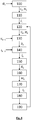
figure 4 montre les principales étapes d'un procédé d'obtention d'une image de reconstruction. - La
figure 1A représente un dispositif de mesure 1 permettant une mise en œuvre de l'invention. Le dispositif de mesure comporte un imageur gamma 2, ou gamma caméra. L'imageur gamma est configuré pour détecter des rayons électromagnétiques ionisants, de type X ou gamma, dont l'énergie est généralement comprise entre 10 keV et 10 MeV. L'imageur gamma comporte des pixels, chaque pixel correspondant à une zone spatiale élémentaire du champ d'observation. Les pixels s'étendent selon un plan de détection P. Lorsque la zone spatiale élémentaire correspondant à un pixel comporte une source émettrice de rayonnement X ou gamma, une partie du rayonnement émis par la source atteint le pixel et est détecté par ce dernier. Ainsi, un pixel de l'image gamma comporte d'autant plus de signal que la zone spatiale élémentaire à laquelle il est associé est irradiante, c'est-à-dire émettrice d'un rayonnement X ou gamma. Dans la suite de la description, les exemples sont donnés en lien avec des sources d'irradiation gamma, ce qui correspond au cas d'application le plus fréquent. Il est directement transposable à des sources d'irradiation X. - L'imageur gamma peut être de type gamma caméra Compton, gamma caméra à collimateur sténopé ou gamma caméra à masque codé. Il peut également s'agir, de façon non exhaustive, d'une gamma caméra dont le collimateur comporte des canaux parallèles, ou des canaux convergents, ou des canaux divergents. Aussi, le terme gamma caméra correspond à un imageur présentant un champ d'observation et configuré pour former une image permettant une localisation de sources d'irradiation dans le champ d'irradiation. Quel que soit le type d'imageur gamma, il permet une formation d'une image gamma comportant des pixels, chaque pixel correspondant à une zone spatiale élémentaire de l'environnement observé. Certains imageurs gamma ont une fonction spectrométrique, au sens où ils permettent une séparation spectrale des rayonnements détectés en différentes bandes spectrales. Lorsqu'on utilise ce type d'imageur, il est possible de former différentes images gamma d'un même champ d'observation, à chaque image correspondant une bande spectrale. L'image peut également être établie en considérant une combinaison de bandes spectrales, qui correspondent au spectre d'émission d'un isotope. La combinaison peut être une somme pondérée. L'image est alors représentative d'une distribution spatiale de l'activité de l'isotope considéré.
- Dans certains imageurs gamma, en particulier les gamma caméra Compton ou les gamma caméras à masques codés, l'image acquise par l'imageur ne permet pas une représentation directe des sources émettrices dans le champ d'observation. L'image acquise subit un traitement, prenant en compte une fonction de réponse de la caméra, de façon à permettre d'obtenir une image gamma sur laquelle l'intensité de chaque pixel correspond à l'intensité d'émission de la zone spatiale élémentaire du champ d'observation associée au pixel.
- Il est usuel que les gamma caméras soient associées à des caméras visibles. Il s'agit de caméras standard, permettant de former une image visible du champ d'observation. Le dispositif représenté sur la
figure 1A comporte une caméra visible 3, solidaire de la gamma caméra 2. La caméra visible 3 et la gamma caméra 2 présentent chacune un champ d'observation, s'étendant autour de leurs axes optiques respectif. Sur lafigure 1A , les axes optiques et champs d'observation de la gamma caméra 2 et de la caméra visible 3 sont notés Ω2, Δ2, Ω3 et Δ3. Généralement, le champ d'observation visible est plus large que le champ d'observation gamma. Les champs d'observation visible et gamma se recoupent : leur intersection est non nulle. Elle est aussi large que possible. - La caméra visible 3 est usuellement disposée à faible distance de la gamma caméra, de telle sorte que leurs axes optiques respectifs sont rapprochés, et de préférence parallèles l'un par rapport à l'autre. Ainsi, au-delà d'une certaine distance, généralement inférieure à 1 m, voire à 50 cm, le champ d'observation de la gamma caméra est inclus dans le champ d'observation de la caméra visible. L'intersection des deux champs d'observation forme le champ d'observation Ω du dispositif.
- De préférence, les axes optiques de la gamma caméra 2 et de la caméra visible 3 sont alignés. La gamma caméra et la caméra visible ont fait l'objet d'une calibration, pour corriger une erreur de parallaxe due au décalage des deux axes optiques, ainsi que pour prendre en compte des distorsions géométriques dues aux lentilles de la caméra visible, en particulier en bordure de champ. La calibration prend également en compte une différence du nombre et de la taille de pixels entre la caméra visible et la gamma caméra. La calibration permet une définition d'une fonction de recalage g.
- Une unité de traitement 4 reçoit les images générées par la gamma caméra 2 et la caméra visible 3. L'unité de traitement d'images est notamment configurée pour fusionner les images résultant de la caméra visible 3 et les images provenant de la gamma caméra 2, en prenant notamment en compte la fonction de recalage. L'objectif est d'obtenir une image composite correspondant à l'image visible, sur laquelle apparaissent les sources irradiantes détectées par la gamma caméra. L'unité de traitement 4 est reliée à une mémoire dans laquelle les instructions de traitement d'image sont codées. L'unité de traitement 4 comporte un processeur, par exemple un microprocesseur, configuré pour mettre en œuvre des instructions correspondant aux étapes décrites ci-après.
- Comme évoqué en lien avec l'art antérieur, la durée d'acquisition d'une image gamma est généralement de plusieurs secondes, voire plusieurs dizaines de secondes. Cela est dû au faible rendement de collecte combiné au faible rendement de détection.
- Sur la
figure 1A ont été représentées des sources irradiantes 10a, 10b et 10c, émettrices de rayonnement γ, ainsi que des éléments structurels 11a, 11b et 11c schématisant l'environnement visible autour des sources irradiantes. Le dispositif 1 occupe une position ainsi qu'une orientation dans l'environnement observé. Lafigure 1B schématise une image gamma obtenue par la gamma caméra. Sur cette dernière, à titre illustratif, les sources irradiantes 10a et 10b, présentes dans le champ d'observation, apparaissent sous la forme de cercles. Lafigure 1C schématise une image visible obtenue par la caméra visible, et permettant d'observer des objets présents dans le champ d'observation. Le terme objet correspond à des éléments structurels présents dans le champ d'observation. Il peut s'agir de parties de génie-civil (parois, portes, fenêtres, arêtes), et/ou de parties d'installations industrielles (tuyaux, équipements spécifiques), et/ou d'objets mobiliers (table, chaise, coffre, équipements divers). - Sur la
figure 2A , on a représenté le dispositif, dans le même environnement, selon une position et une orientation différente de celles représentées sur lafigure 1A . Généralement, du fait de la sensibilité de la gamma caméra, plusieurs secondes, voire minutes, d'acquisition sont nécessaires de façon à obtenir une représentation de chaque source irradiante selon un rapport signal sur bruit suffisant. Durant l'acquisition d'une image gamma, la gamma caméra doit de préférence être maintenue immobile. - La
figure 2B montre une image gamma obtenue. Les contours en traits pleins montrent les sources irradiantes 10a, 10b et 10c. Sur cette image, les pointillés représentent les positions des sources irradiantes 10a et 10b telles qu'elles apparaissent sur lafigure 2B . Sur l'image gamma, le changement d'orientation de la gamma caméra entre lesfigures 2A et 2B se traduit par un déplacement des sources irradiantes, ce dernier étant illustré par deux flèches. Il est possible de prendre en compte un environnement, dans lequel chaque source irradiante détectée par la gamma caméra présente une position fixe, matérialisée par des coordonnées bidimensionnelles dans un espace objet. Lorsque la gamma caméra est déplacée dans l'espace objet, les sources gamma présentes dans le champ d'observation sont détectées et produisent un signal exploitable sur l'image gamma. Généralement, le signal formé sur l'image gamma présente un rapport signal sur bruit relativement faible, ce dernier dépendant du niveau d'irradiation produit par la source sur la gamma caméra. Afin d'améliorer le rapport signal sur bruit, le signal produit par une source irradiante sur une gamma caméra peut être accumulé, par exemple par une moyenne glissante. Ainsi, à chaque fois qu'une source gamma est présente dans le champ d'observation, le signal qu'elle génère sur l'image gamma est pris en compte, de façon à améliorer la statistique de détection liée à la source. L'image gamma est alors intégrée à un procédé de reconstruction, prenant en compte des images gamma acquises préalablement et/ou postérieurement. - A chaque acquisition d'une image gamma est associée une image visible acquise par la caméra visible. La caméra visible 3 acquiert une image visible de la scène observée. Le champ d'observation Ω du dispositif d'imagerie, c'est-à-dire à l'intersection des champs d'observation respectifs de la gamma caméra et de la caméra visible, définit un espace objet. L'espace objet comporte des points (x,y), chaque point étant associé à un pixel (u,v) de l'image gamma. Les pixels appartiennent à un plan de détection P, dans lequel est formée l'image gamma. Les points (x,y) du champ d'observation ont des coordonnées bidimensionnelles, et correspondent à des pixels de l'image visible, après prise en compte de la fonction de recalage.
- Un élément important de l'invention est que les points du repère objet sont considérés comme appartenant à un même plan de projection objet Po. Le champ d'observation angulaire Ω2 de la gamma caméra, s'étendant autour de l'axe optique Δ2 décrit une portion d'une sphère S, représentée sur la
figure 3 . Le plan objet Po correspond à un plan, tangent à la sphère S, et perpendiculaire à l'axe optique Δ2. Les sources irradiantes présentes dans le champ d'observation sont considérées comme coplanaires et appartenant au plan objet. La distance entre le plan de détection et le plan objet est une distance arbitraire, qui peut ne pas être connue. Elle n'est pas prise en compte dans le procédé de reconstruction décrit ci-après. Selon une variante, les sources irradiantes sont considérées comme appartenant à une même surface tridimensionnelle, s'étendant face au plan de détection P. - Après un traitement d'image, permettant d'effectuer une fusion d'image (seuillage et/ou superposition avec prise en compte d'une transparence), et de prendre en compte de la fonction de recalage, les niveaux d'irradiation associés aux points du repère objet, et considérés comme significatifs, sont superposés à l'image visible Vk sous la forme d'un code couleur.
- Ainsi, le champ d'observation Ω du dispositif délimite une partie du plan objet, dans laquelle la reconstruction est effectuée.
- La correspondance entre chaque point (x, y) du plan objet PO et de chaque pixel (u, v) de l'image gamma dépend d'une fonction de réponse spatiale de la gamma caméra. Lorsque des photons gamma sont émis en un point du repère objet (x,y), vers la gamma caméra, la trace qu'ils forment sur l'image gamma résulte d'une fonction de réponse spatiale F de la caméra. Lorsqu'on met en œuvre une gamma caméra basée sur un collimateur de type sténopé, la fonction de réponse spatiale prend en compte l'ouverture du sténopé. Elle peut être approximée par une image d'une source irradiante centrée dans le champ d'observation, qui est utilisée en tant que réponse impulsionnelle. Lorsqu'on met en œuvre une gamma caméra à masque codé, la fonction de réponse prend en compte la géométrie du masque. Lorsqu'on met en œuvre une gamma caméra Compton, la fonction de réponse dépend de l'énergie détectée et de la position des pixels ayant détecté un rayonnement, dans le plan de détection P. Ainsi, dans une gamma caméra Compton, la fonction de réponse peut varier à chaque instant de mesure.
- La correspondance entre un point du champ d'observation et un pixel de l'image gamma peut par exemple être réalisée par un produit de convolution de l'image gamma par la fonction de réponse (notamment dans le cas d'une gamma caméra dotée d'un collimateur sténopé), ou par une projection rectilinéaire (notamment dans le cas d'une gamma caméra dotée d'un collimateur à masque codé). La projection peut également être d'un autre type, par exemple, et à titre non limitatif, stéréographique, ou orthographique.
- Ainsi, la fonction ,de réponse F permet de passer du plan de détection, dans lequel l'image gamma est acquise, au plan objet PO, correspondant à la scène observée, et dans lequel la position de sources irradiantes est recherchée. Dans la suite de la description, la notation F correspond à une projection d'une image formée dans le plan objet vers le plan de détection. La notation F- correspond à une rétroprojection d'une image formée dans le plan de détection P vers le plan objet P o. Dans une première approche, F est un opérateur linéaire et F - correspond à une transposée de F.
- Si Mk est une image gamma acquise à un instant tk , et Ik est une image montrant une reconstruction des sources d'irradiation dans le champ Ω k observé à l'instant tk , on a :

- (x,y) représentent des coordonnées, dans le plan objet, parallèle au plan de détection, et correspondant à des coordonnées (u, v) dans plan de détection ;
- Ik (x,y) correspond à une image de la répartition de sources irradiantes dans le champ d'observation. Il s'agit d'une matrice bidimensionnelle dont chaque terme représente un taux d'émission, dans une bande spectrale, ou dans plusieurs bandes spectrales combinées, d'une source irradiante dans le plan objet, en des coordonnées (x,y), à l'instant de mesure tk. Comme précédemment décrit, lorsque plusieurs bandes spectrales en fonction du spectre d'émission d'un isotope, l'image Ik est représentative d'une distribution spatiale de l'activité de l'isotope. D'une façon générale, Ik correspond à l'estimation de la répartition de l'irradiation après prise en compte d'au moins une image gamma acquise par la gamma caméra. Chaque terme de l'image Ik (x,y) correspond à une estimation d'un taux d'émission de photons gamma (ou X), ou d'une activité, au point (x,y) du plan objet. La dimension de l'image Ik est Nx, Ny, où Nx et Ny désignent le nombre de pixels de la gamma caméra respectivement selon un axe horizontal et un axe vertical. La dimension de la matriceIk est identique à celle d'une image gamma acquise par la gamma caméra.
- F - est un opérateur de rétroprojection, permettant un passage dans le plan objet Po à partir du plan de détection P.
- Le fait de représenter la position des sources irradiantes selon une distribution spatiale (ou carte) bidimensionnelle permet une superposition simple de l'image de reconstruction sur une image visible acquise par la caméra visible.
- Le procédé, dont les principales étapes sont schématisées sur la
figure 4 , permet d'établir une localisation de sources gamma dans un environnement, tout en permettant un déplacement relatif du dispositif de mesure 1 par rapport aux sources irradiantes. D'une façon générale, le dispositif 1 est déplacé par rapport à l'environnement et au cours du déplacement, plusieurs acquisitions d'images gamma sont réalisées. Entre deux acquisitions successives, le déplacement relatif du repère objet par rapport au dispositif 1 est enregistré. L'objectif est de permettre un suivi, dans le plan objet, de la position de sources irradiantes se déplaçant par rapport au dispositif de mesure 1. Le déplacement relatif peut être un déplacement du dispositif de mesure par rapport à une source irradiante, cette dernière étant fixe dans l'environnement. Il peut également s'agir d'un déplacement de la source irradiante par rapport au dispositif de mesure, ce dernier étant fixe dans l'environnement. - Au cours d'une première acquisition, le dispositif de mesure 1 est disposé selon une première position, à un premier instant t 1. Une acquisition d'une image gamma M 1 est réalisée. D'une façon générale, la durée de chaque acquisition d'image gamma est comprise entre 1 ms et 5 s, et de préférence comprise entre 50 ms et 500 ms, par exemple 100 ms. Sur l'image gamma, chaque source irradiante présente dans le champ apparaît sous la forme d'une trace, dont l'intensité dépend de l'irradiation, générée par la source irradiante, et détectée par la gamma caméra.
- Lorsque la gamma caméra dispose d'une fonction spectrométrique, une image gamma est acquise dans une bande spectrale d'énergie ΔE donnée, ou dans une combinaison de bandes d'énergie, comme précédemment décrit.
- Une image visible V 1 est acquise au premier instant t 1, ou à un instant considéré comme consécutif du premier instant t 1. Le principal objectif de l'image visible initiale V 1 est d'obtenir des points remarquables sur la scène visible observée. Les points remarquables, et leur utilisation, sont plus largement décrits dans l'étape 130.
- L'image gamma M 1 est divisée par une image d'estimation M̂ 1. L'image d'estimation M̂ 1 correspond à une estimation de l'image gamma M 1. Lors de la première acquisition, l'image d'estimation M̂ 1 est établie a priori. Elle est par exemple uniforme et constituée de 1.
- Le ratio

- Le terme d'erreur U 1 est propagé dans le plan objet, de façon à effectuer une mise à jour d'une image de reconstruction I 1 de telle sorte que :


- L'image I 0(x, y) est une image d'initialisation, déterminée a priori, ne comportant par exemple que des réels positifs, par exemple que des 1.
- Suite aux étapes 100 à 110, les étapes 120 à 190 sont mises en œuvre de façon itérative. A chaque itération correspond un rang d'itération k. k est un entier compris entre 2 et K. K correspond au rang d'itération lors de l'arrêt des itérations.
- Etape 120 : Acquisition d'une image gamma Mk et d'une image visible Vk à un instant tk .
- Une image visible Vk est acquise au cours d'un instant tk . Une image gamma Mk est également acquise à l'instant tk, ou à un instant d'acquisition considéré comme simultané de l'instant tk . De préférence, les durées d'acquisition de chaque image gamma Mk sont identiques à chaque itération k.
- L'objectif de cette étape est de former un champ de déplacements Dk représentatif d'un déplacement bidimensionnel de l'image visible V k-1 par rapport à l'image visible Vk . L'image V k-1 est une image visible acquise au cours d'une itération précédente ou, lorsque k = 2, au cours de l'étape 100. Le champ de déplacements Dk comporte, en différentes coordonnées (x,y) du plan objet, un vecteur de déplacement dk, correspondant à un déplacement selon l'axe X et un déplacement selon l'axe Y. Chaque vecteur de déplacement est un vecteur de dimension égale à 2. Ainsi, on ne prend en compte qu'un déplacement bidimensionnel, dans un plan parallèle au plan objet PO, ou confondu avec ce dernier.
- Le dispositif 1 peut avoir été déplacé ou réorienté entre les acquisitions des images V k-1 et Vk . De façon alternative, certains éléments de l'espace objet peuvent avoir été déplacés entre les deux acquisitions. C'est notamment le cas lorsqu'une source irradiante se déplace dans le repère objet.
- Sur chaque image V k-1 et Vk, on identifie des points remarquables. Les points remarquables sont des points aisément identifiables par un traitement d'image classique. Il s'agit par exemple de points formant un contour ou une arête d'un objet, ou de points particulièrement contrastés du point de vue de l'intensité ou de la couleur. Ainsi, un point remarquable peut être un point correspondant à un Laplacien ou gradient d'intensité élevé.
- Le nombre de points remarquables détectés sur chaque image V k-1 et Vk est de préférence compris entre quelques dizaines et plusieurs centaines voire plus de 1000. Les points remarquables détectés sur les deux images V k-1 et Vk forment respectivement un ensemble E k-1 et un ensemble Ek .
- La détection des points remarquables sur une image peut être effectuée en mettant en oeuvre un algorithme, par exemple un détecteur de coins de Harris. Suite à leur détection, les points remarquables sont caractérisés, de façon à pouvoir permettre leur éventuelle identification sur les deux images V k-1 et Vk . La caractérisation vise à caractériser chaque point remarquable et son environnement. Cela peut être effectué en mettant en œuvre des algorithmes de description locale, connus de l'homme du métier, de type DAISY ou LUCID ou FREAK. De tels algorithmes sont usuellement désignés "feature description algorithms". A chaque point remarquable est associé un vecteur descripteur, permettant de le reconnaître sur les deux images V k-1 et Vk .
- Sur la base de leur description et de leur caractérisation, les points remarquables identifiés sur les images V k-1 et Vk font l'objet d'un appariement, de façon à établir des couples de points remarquables, chaque couple reliant un point remarquable de l'image V k-1 et un point remarquable de l'image Vk, les points remarquables appariés présentant un vecteur descripteur considéré comme identique Les points remarquables appariés correspondent à un même point de la scène observée, et apparaissant sur les deux images visibles V k-1 et Vk . L'appariement est une opération usuellement désignée par le terme "Matching".
- De préférence, les points remarquables de chaque image sont considérés comme coplanaires : ils s'étendent selon un plan parallèle au plan objet.
- A partir des points remarquables appariés, on effectue un maillage des images V k-1 et Vk, respectivement à partir des ensembles E k-1 et Ek . Il peut s'agir d'un maillage de Delaunay, définissant des mailles triangulaires, chaque maille s'étendant entre trois points remarquables différents les uns des autres, et appariés sur les deux images V k-1 et Vk . Pour chaque sommet du maillage, présent dans les deux images V k-1 et Vk, un déplacement bidimensionnel dk est estimé. Pour une mise en œuvre optimale de l'invention, il est préférable que le déplacement du dispositif, ou des éléments constituant le repère objet, se déplacent relativement lentement, de façon à maximiser le nombre de sommets du maillage présents dans les deux images V k-1 et Vk . Un déplacement suffisamment lent et fluide et une luminosité suffisante permet également d'éviter un effet de flou ou de bougé dans l'image visible. De préférence, les champs d'observation avant et après un déplacement se recoupent à au moins 50%, voire au moins 80%, voire 90%.
- On dispose alors, en chaque sommet du maillage présent dans les deux images V k-1 et Vk, d'une estimation d'un vecteur de déplacement dk. Le vecteur déplacement n'étant défini qu'au niveau des sommets présents dans les images V k-1 et Vk, une interpolation, par exemple une interpolation linéaire, est effectuée, de façon à obtenir une estimation d'un déplacement dk dans chaque point (x,y) du champ d'observation Ω k du dispositif, au moins à l'intérieur du maillage. Plus précisément, le déplacement est déterminé, au moins dans un maillage établi dans l'intersection des champs d'observation Ω k-1 et Ω k correspondant respectivement aux images visibles V k-1 et Vk respectivement acquises aux instants de mesure k-1 et k. On forme alors le champ de déplacements Dk, dont chaque terme correspond au vecteur de déplacement dk (x,y) déterminé, au moins en chaque point (x,y) inclus dans le maillage.
- Le champ de déplacements Dk, à l'extérieur du maillage, peut être estimé par extrapolation, à partir des vecteurs de déplacement dk (x,y) établis à l'intérieur du maillage. Cela permet d'obtenir un vecteur champ de déplacements Dk dans tout le champ d'observation de l'image. Dans un mode de réalisation, le dispositif comporte un capteur de mouvement 5, permettant d'estimer un mouvement angulaire du dispositif entre les acquisitions des images visibles V k-1 et Vk . Le capteur de mouvement peut être une centrale magnéto-inertielle, ou comporter au moins un gyromètre. Dans ce cas, le champ de déplacements, à l'extérieur du maillage, peut être estimé en combinant le champ de déplacements obtenu à l'intérieur du maillage avec le mouvement du dispositif entre les deux images.
- D'autres méthodes permettent d'estimer un champ de déplacements Dk entre deux images successives. Il peut par exemple s'agir de méthodes usuellement désignées par le terme "Optical Flow", qui permettent d'estimer un faible déplacement entre deux images successives.
- Le champ de déplacements Dk est déterminé, au moins en partie, par l'observation d'un déplacement d'objets présents dans les images visibles V k-1 et Vk . Selon une première possibilité, les objets sont fixes dans la scène observée : le champ de déplacements est établi en observant un déplacement d'objets, ou de parties d'objets, présents dans les deux images V k-1 et Vk . Dans ce cas, le champ de déplacements correspond au déplacement de la caméra par rapport aux objets présents dans le champ d'observation de cette dernière. Selon une deuxième possibilité, les objets sont mobiles alors que le dispositif n'a pas été déplacé entre l'acquisition des images V k-1 et Vk . Dans ce cas, le champ de déplacements Dk correspond au déplacement des objets relativement à la caméra visible. D'une façon plus générale, le champ de déplacements Dk correspond au déplacement relatif d'objets, présents dans le champ d'observation de la caméra visible, relativement à cette dernière.
- Lorsqu'il n'est pas possible de déterminer le champ de déplacements à l'extérieur du maillage, par extrapolation ou par utilisation de mesures de mouvement, le champ de déplacements à l'extérieur du maillage est considéré comme uniforme, et de valeur constante, par exemple un vecteur de déplacement nul.
- A la suite de cette étape, on dispose d'un champ de déplacements Dk de dimension (2, Nx, Ny). A chaque point (x,y) considéré, on établi un champ de déplacements


- A partir de l'image de reconstruction I k-1(x,y) résultant d'une itération précédente, ou résultant de l'initialisation, et connaissant le champ de déplacements Dk, on estime une image de reconstruction Îk, en prenant en compte la fonction de recalage. Cette étape constitue un élément important de l'invention.
- Cette étape est basée sur l'hypothèse que le déplacement de la position des sources irradiantes, sur l'image de reconstruction Ik , entre les instants k - 1 et k, est obtenu en considérant le champ de déplacements Dk mesuré entre deux images visibles successives respectivement associées aux instants k - 1 et k, les images visibles V k-1 et Vk étant respectivement associées aux images gamma M k-1 et Mk .
- Ainsi :

- × est un opérateur de multiplication terme à terme (produit de Hadamard)
- I k-1 correspond à l'image de reconstruction résultant d'une itération précédente. Il s'agit d'une matrice, de même dimension qu'une image gamma Mk, et dont chaque point correspond à un taux d'émission, dans une bande spectrale donnée ou dans une combinaison de bandes spectrales, ou à une activité d'un isotope.
- B est un filtre permettant d'effectuer un lissage de l'image I k-1. Il peut s'agir d'un filtre passe bas, par exemple un filtre gaussien. La convolution de l'image I k-1 par le filtre de lissage B permet d'effectuer un effet de flou sur l'image de reconstruction I k-1. Le recours à un tel filtre permet d'établir un a priori sur la position des sources irradiantes telle que décrite par l'image de reconstruction I k-1. Selon une alternative, le filtrage peut être effectué selon l'expression :
 correspond à la fonction de recalage.
 (Dk ) est une fonctionnelle prenant en compte déplacement dans le plan objet, en prenant en compte la fonction de recalage
 entre la caméra visible et la caméra gamma.
- I k-1 ∘ g(Dk ) traduit l'image de reconstruction I k-1 après application du vecteur de déplacement recalé.
- En chaque point (x,y) du champ d'observation, Dk permet de définir un déplacement

 (Dk ) permet d'établir un déplacement, dans le plan objet, en fonction du déplacement Dk . Elle permet d'estimer des coordonnées (xk,yk ) à l'instant k en fonction de coordonnées (x k-1,y k-1) à l'instant k - 1, de telle sorte que :


- Où gX et gY correspondent à des composantes de la fonction de recalage établies respectivement selon l'axe X et selon l'axe Y.
- Ainsi,(Dk ) est une fonctionnelle permettant un passage entre (x k-1, y k-1) et (xk,yk ) tel qu'explicité par les expressions (5.1) et (5.2). Il s'agit d'un changement de variables.

- L'exposant α est strictement positif est strictement inférieur à 1 : 0 < α ≤ 1. L'exposant α permet une prise en compte d'un effet mémoire : plus α se rapproche de 1, plus on conserve la mémoire des acquisitions d'images gamma précédentes.
- Le champ de déplacements Dk est établi par l'observation d'un déplacement d'objets entre les images visibles V k-1 et Vk, dans le champ d'observation de la caméra visible. Ainsi, le déplacement des sources irradiantes, sur les deux images de reconstruction I k-1 et Îk est basé sur la détection d'objets, formant des points remarquables dans les images visibles V k-1 et Vk, leur appariement, et le calcul de leurs déplacements respectifs entre les deux images visibles. Leur déplacement permet d'établir un champ de déplacements Dk dans l'image visible, qui est affecté à l'image gamma, après application de la fonction de recalage.
- Aussi, à l'application de la fonction de recalage près, de déplacement des sources d'irradiation est considéré comme pouvant être établi à partir du champ de déplacements calculé sur la base des images visibles. Un point important de l'invention est le fait que les mouvements des objets observés sur l'image visible sont considérés comme représentatifs des mouvements des sources gamma, ces dernières étant représentées sur l'image de reconstruction. Cela limite significativement la complexité des calculs ainsi que les ressources nécessaires pour effectue les calculs. Le procédé ne nécessite pas une mise en œuvre de techniques complexes, telles que la triangulation, ou d'estimation d'un positionnement tridimensionnel des sources irradiantes dans l'environnement.
- L'image de reconstruction estimée Îk ,résultant de l'étape 140, est projetée dans le plan de détection, de façon à estimer l'image gamma M̂k correspondant à l'itération k. L'image gamma M̂k est estimée selon l'expression

- Où F correspond à un opérateur de projection entre le plan objet Po et le plan de détection P.
- Au cours de cette étape, à partir de l'image Mk acquise à l'instant k, et résultant de l'étape 120 et de l'estimation M̂k résultant de l'étape 140, on calcule l'erreur de mesure :

- Le terme d'erreur Uk est rétropropagé dans le plan objet selon l'expression :

- Au cours de cette étape, l'image de reconstruction, correspondant à l'instant k, est mise à jour selon l'expression,

- Selon un mode de réalisation, on prend en compte une fonction non linéaire h, de telle sorte que

- Ainsi, à chaque instant de mesure k, l'image de reconstruction Ik est mise à jour en prenant en compte l'image gamma Mk acquise à l'instant de mesure. La prise en compte de l'image gamma Mk est effectuée par le biais de l'erreur rétropropagée Wk.
- L'image de reconstruction Ik est définie dans une intersection entre le plan objet PO et le champ d'observation Ω k à l'instant de mesure k. De préférence, l'image de reconstruction Ik n'est pas définie à l'extérieur du champ d'observation Ω k à l'instant de mesure k. Cela permet de simplifier le processus de reconstruction, en ne prenant pas en compte des sources d'irradiation potentiellement présentes en dehors du champ d'observation Ω k . L'image de reconstruction ne comporte alors que des positions de sources irradiantes présentes dans le champ d'observation à l'instant de mesure k, sur la base d'images gamma M k acquises à l'instant de mesure ou à des images gamma acquises à des instants antérieurs, précédent l'instant de mesure. A chaque déplacement du dispositif de mesure 1, l'étendue spatiale de l'image de reconstruction est modifiée, de façon à se limiter à l'intersection entre le plan objet PO et le champ d'observation Ω k à l'instant de mesure k.
- L'image de reconstruction peut avoir une dimension inférieure ou égale à la dimension de chaque image gamma.
- L'image de reconstruction Ik est dotée d'un certain niveau de transparence, puis est superposée sur l'image visible Vk, la superposition étant réalisée ne prenant en compte la fonction de recalage. Cela permet d'effectuer une correspondance entre les objets observés sur l'image visible et les sources irradiantes représentées dans l'image de reconstruction.
- Réitération des étapes 130 à 190, en incrémentant l'indice d'itération k.
- Selon un mode de réalisation, le dispositif comporte un capteur de mouvement 5, par exemple de type centrale inertielle. Le capteur de mouvement comporte un gyromètre, éventuellement complété par un accéléromètre et/ou un magnétomètre). D'une façon générale, le capteur de mouvement permet d'obtenir un mouvement angulaire entre deux instants d'acquisition successifs. L'information résultant de la centrale inertielle peut être prise en compte dans l'étape 130, de façon à limiter les risques d'erreur dans l'appariement des points remarquables. Elle peut également être utilisée pour compléter le champ de déplacements Dk en dehors du maillage formé entre les points remarquables appariés. Le mouvement de translation de la caméra et le positionnement des objets peut également être estimé par d'autres dispositif de type LIDAR, système de localisation GPS, balises fixes radiofréquentielles ou centrale inertielle de qualité «navigation».
- Selon un mode de réalisation, la gamma caméra dispose d'une fonction spectrométrique. Les étapes 100 à 180 sont mises en œuvre simultanément, dans chaque bande d'énergie ΔE. On peut alors obtenir autant d'images de reconstruction que de bandes d'énergie considérées.
- Les étapes 100 à 180 peuvent également être mis en œuvre sur la base d'images gamma respectivement acquises dans différentes bandes d'énergie, puis combinées, comme précédemment décrit, de façon à tenir compte d'un spectre d'émission d'un isotope radioactif préalablement sélectionné. Dans ce cas, l'image de reconstruction est assimilable à une distribution spatiale de l'activité de l'isotope radioactif, dans le champ d'observation.
- L'invention pourra être mise en œuvre sur différentes installations nucléaires, ou, plus généralement, pour des opérations de recherche et de caractérisation de sources radioactives.
Claims (15)
- Procédé de formation d'une image de reconstruction (Ik ), l'image de reconstruction montrant une position (x,y) de sources irradiantes (10a, 10b) dans un champ d'observation (Ω), le procédé mettant en œuvre un dispositif (1) comportant une gamma caméra (2), reliée à une caméra visible (3), le dispositif étant tel que :- la gamma caméra et la caméra visible définissent le champ d'observation (Ω);- la caméra visible (3) est configurée pour former une image visible (Vk ) du champ d'observation (Ω);- la gamma caméra comporte des pixels, configurés pour détecter un rayonnement électromagnétique ionisant généré par une source irradiante éventuellement présente dans le champ d'observation, les pixels s'étendant selon un plan de détection (P) ;- la gamma caméra est configurée pour former une image gamma (Mk ), permettant d'estimer une position de sources irradiantes, dont le rayonnement est détecté par des pixels, dans le champ d'observation ;le procédé comportant les étapes itératives suivantes :a) à un instant de mesure initial (k=1), acquisition d'une image gamma initiale (M 1) par la gamma caméra et acquisition d'une image visible initiale (V 1) par la caméra visible;b) à partir de l'image gamma initiale et de l'image visible initiale, initialisation de l'image de reconstruction (I 1);c) acquisition d'une image gamma (Mk ) par la gamma caméra et acquisition d'une image visible (Vk ) par la caméra visible à un instant de mesure (k);d) comparaison de l'image visible (Vk ) à l'instant de mesure avec une image visible (V k-1) à un instant antérieur (k-1), l'instant antérieur étant l'instant de mesure initial ou un précédent instant de mesure, puis, en fonction de la comparaison, estimation d'un champ de déplacements (Dk ) entre les images visibles respectivement acquises à l'instant antérieur et à l'instant de mesure ;e) mise à jour de l'image de reconstruction (Ik ), en fonction :- d'une image de reconstruction (I k-1) établie à l'instant antérieur;- du champ de déplacements (Dk ) résultant de l'étape d) ;- et de l'image gamma (Mk ) acquise à l'instant de mesure ;f) éventuellement superposition de l'image de reconstruction, ou d'une partie de l'image de reconstruction, et de l'image visible ;g) réitération des étapes c) à f) en incrémentant l'instant de mesure, jusqu'à un arrêt des itérations ;le dispositif étant déplacé entre au moins deux instants de mesure, de telle sorte qu'à chaque instant de mesure (k) correspond un champ d'observation (Ω k ).
- Procédé selon la revendication 1, dans lequel à chaque instant de mesure, chaque pixel ayant détecté un rayonnement issu d'une source irradiante est associé à une position (x,y) dans une surface objet (PO), s'étendant face au plan de détection, l'image de reconstruction (Ik ) correspondant à une distribution spatiale des sources irradiantes à l'intérieur du champ d'observation (Ω k ) à l'instant de mesure (k) sur la surface objet.
- Procédé selon la revendication 2, dans lequel la surface objet est un plan objet, s'étendant parallèlement au plan de détection (P), chaque position (x,y) étant coplanaire.
- Procédé selon l'une quelconque des revendications 2 ou 3, dans lequel l'image de reconstruction (Ik ), à l'instant de mesure, n'est définie que dans une intersection entre le champ d'observation (Ω k ) à l'instant de mesure (k) et la surface objet (PO).
- Procédé selon l'une quelconque des revendications précédentes, dans lequel l'étape e) lors de chaque instant de mesure, comporte- i) estimation d'une image de reconstruction (Îk ), à l'instant de mesure, à partir de l'image de reconstruction (I k-1) établie à l'instant antérieur et du champ de déplacements (Dk ) résultant de l'étape d) ;- ii) à partir de l'image de reconstruction estimée (Îk ), estimation de l'image gamma (M̂k ) à l'instant de mesure ;- iii) comparaison de l'image gamma (M̂k ) estimée à l'instant de mesure et l'image gamma (Mk ) acquise à l'instant de mesure ;- iv) en fonction de la comparaison, mise à jour de l'image de reconstruction (Ik ) à l'instant de mesure.
- Procédé selon l'une quelconque des revendications précédentes, comportant une détermination d'une fonction de recalage (g), représentative d'un décalage spatial entre la gamma caméra (2) et la caméra visible (3), la fonction de recalage étant utilisée dans l'étape e).
- Procédé selon l'une quelconque des revendications précédentes, dans lequel l'étape d) comporte une sélection de points remarquables sur les images visibles acquises respectivement à l'instant antérieur et à l'instant de mesure, le champ de déplacements (Dk ) comportant un déplacement bidimensionnel des points remarquables sélectionnés.
- Procédé selon la revendication 7, dans lequel les points remarquables sont considérés comme appartenant à une même surface.
- Procédé selon l'une quelconque des revendications précédentes, dans lequel l'étape d) comporte :- une extraction de premiers points remarquables de l'image visible (Vk ) acquise à l'instant de mesure ;- une extraction de deuxièmes points remarquables de l'image visible (V k-1) acquise à l'instant antérieur ;- un appariement de premiers points remarquables et des deuxièmes points remarquables, de façon à former des couples de points appariés, chaque couple étant formé d'un premier point remarquable et d'un deuxième point remarquable ;- pour chaque couple de points appariés, détermination d'un déplacement (dk (x,y));- obtention du champ de déplacements (Dk ) à partir des déplacements déterminés pour chaque couple de points appariés.
- Procédé selon la revendication 9, comportant :- une élaboration d'un premier maillage du champ d'observation, à l'instant de mesure, à l'aide de premiers points remarquables, ces derniers formant des premiers sommets du premier maillage;- une élaboration d'un deuxième maillage du champ d'observation, à l'instant antérieur à l'aide de deuxièmes points remarquables, ces derniers formant des deuxièmes sommets du deuxième maillage ;- en fonction des déplacements déterminés pour différents couples de points remarquable, détermination, par interpolation, de déplacements en des points appartenant au premier maillage et au deuxième maillage.- détermination du champ de déplacements (Dk ) à partir du déplacement de chaque sommet apparié et des déplacements interpolés.
- Procédé selon l'une quelconque des revendications précédentes, dans lequel :- le dispositif est couplé à un capteur de mouvement, de façon à estimer un mouvement du dispositif entre deux instants successifs ;- l'étape d) prend en compte le mouvement estimé pour estimer ou valider le champ de déplacements.
- Procédé selon l'une quelconque des revendications précédentes, dans lequel la gamma caméra est configurée pour acquérir, lors des étapes a) et c) des images gamma simultanément dans différentes bandes d'énergies, les étapes b) et d) à f) étant mises en œuvre dans chaque bande d'énergie respectivement, de façon à obtenir, à chaque instant de mesure, une image de reconstruction dans différentes bandes d'énergie.
- Procédé selon l'une quelconque des revendications précédentes, dans lequel la gamma caméra est configurée pour acquérir, lors des étapes a) et c) des images gamma simultanément dans différentes bandes d'énergies, le procédé comportant une combinaison linéaire de différentes images gamma respectivement acquises, au même instant de mesure, dans différentes bandes d'énergie, de façon à obtenir une image gamma combinée, les étapes b) et d) à f) étant mises en œuvre à partir d'une image gamma combinée formée à chaque instant de mesure.
- Procédé selon la revendication 13, dans lequel une image combinée est formée par une somme pondérée d'images gamma acquises dans différentes énergies, la somme pondérée utilisant des facteurs de pondération, les facteurs de pondération étant déterminé à partir d'un spectre d'émission d'un isotope radioactif, de telle sorte que chaque image de reconstruction est représentative d'une distribution spatiale de l'activité de l'isotope dans le champ d'observation correspondant à l'instant de mesure.
- Dispositif (1) comportant :- une gamma caméra (2), comportant des pixels, définissant un champ d'observation gamma (Ω2), la gamma caméra étant configurée pour déterminer une position de sources irradiantes X ou gamma dans le champ d'observation gamma (Ω2);- une caméra visible (3), permettant de former une image visible d'un champ d'observation visible (Ω3);- l'intersection du champ d'observation gamma et du champ d'observation visible étant non nulle, et définissant un champ d'observation (Ω) du dispositif;- une unité de traitement (4), configurée pour recevoir, en différents instants de mesure (k):• une image gamma, formée par la gamma caméra ;• une image visible formée par la caméra visible ;l'unité de traitement étant configurée pour mettre en œuvre les étapes b) ainsi que d) à g) d'un procédé selon l'une quelconque des revendications précédentes.
Applications Claiming Priority (1)
| Application Number | Priority Date | Filing Date | Title |
|---|---|---|---|
| FR1911567A FR3102254B1 (fr) | 2019-10-16 | 2019-10-16 | Procédé de suivi de la position d'une source irradiante |
Publications (2)
| Publication Number | Publication Date |
|---|---|
| EP3809164A1 true EP3809164A1 (fr) | 2021-04-21 |
| EP3809164B1 EP3809164B1 (fr) | 2022-07-27 |
Family
ID=69743326
Family Applications (1)
| Application Number | Title | Priority Date | Filing Date |
|---|---|---|---|
| EP20201649.9A Active EP3809164B1 (fr) | 2019-10-16 | 2020-10-13 | Procédé de suivi de la position d'une source irradiante |
Country Status (4)
| Country | Link |
|---|---|
| US (1) | US11353599B2 (fr) |
| EP (1) | EP3809164B1 (fr) |
| CN (1) | CN112669347B (fr) |
| FR (1) | FR3102254B1 (fr) |
Families Citing this family (3)
| Publication number | Priority date | Publication date | Assignee | Title |
|---|---|---|---|---|
| KR102390955B1 (ko) * | 2020-03-02 | 2022-04-25 | 한국수력원자력 주식회사 | 원자력 발전소의 해체 지역의 방사선원 영상화 장치 |
| CN114001707B (zh) * | 2021-10-28 | 2022-07-01 | 中国科学院高能物理研究所 | 基于四目编码伽马相机对辐射热点进行深度测量的方法 |
| CN114200500A (zh) * | 2021-12-02 | 2022-03-18 | 清华大学 | 一种核辐射污染快速搜索测量装置及测量方法 |
Citations (1)
| Publication number | Priority date | Publication date | Assignee | Title |
|---|---|---|---|---|
| CN103163548B (zh) * | 2013-03-07 | 2016-01-20 | 北京永新医疗设备有限公司 | 基于伽马相机的放射性物质探测方法及其装置和系统 |
Family Cites Families (8)
| Publication number | Priority date | Publication date | Assignee | Title |
|---|---|---|---|---|
| FR2950979B1 (fr) * | 2009-10-07 | 2012-12-07 | Commissariat Energie Atomique | Procede de traitement de donnees issues d'un detecteur de rayonnements ionisants |
| CN102788989B (zh) * | 2012-08-08 | 2015-05-27 | 北京永新医疗设备有限公司 | 用于伽马放射源定位仪的伽马相机及其伽马放射源定位仪 |
| CN103996213A (zh) * | 2014-04-01 | 2014-08-20 | 平生医疗科技(昆山)有限公司 | 一种pet图像重建方法及系统 |
| CN104237959A (zh) * | 2014-08-21 | 2014-12-24 | 北京辛耕普华医疗科技有限公司 | 对放射性物质实时动态追踪定位的方法和设备 |
| FR3027119B1 (fr) * | 2014-10-09 | 2016-12-23 | Commissariat Energie Atomique | Dispositif d'imagerie duale |
| JP6720229B2 (ja) * | 2015-07-09 | 2020-07-08 | コーニンクレッカ フィリップス エヌ ヴェKoninklijke Philips N.V. | 積層検出器を用いる同時x線及びガンマ光子イメージングのためのデバイス及び方法 |
| US11402515B2 (en) * | 2016-05-31 | 2022-08-02 | David W. Holdsworth | Gamma probe and multimodal intraoperative imaging system |
| ES2681094B1 (es) * | 2017-02-10 | 2019-10-21 | Consejo Superior Investigacion | Sistema y metodo para la identificacion volumetrica e isotopica de distribuciones de escenas radioactivas |
-
2019
- 2019-10-16 FR FR1911567A patent/FR3102254B1/fr not_active Expired - Fee Related
-
2020
- 2020-10-13 EP EP20201649.9A patent/EP3809164B1/fr active Active
- 2020-10-15 US US17/070,977 patent/US11353599B2/en active Active
- 2020-10-16 CN CN202011110216.5A patent/CN112669347B/zh active Active
Patent Citations (1)
| Publication number | Priority date | Publication date | Assignee | Title |
|---|---|---|---|---|
| CN103163548B (zh) * | 2013-03-07 | 2016-01-20 | 北京永新医疗设备有限公司 | 基于伽马相机的放射性物质探测方法及其装置和系统 |
Non-Patent Citations (1)
| Title |
|---|
| CHEN SI ET AL: "A new compact gamma camera with super resolution capability and high sensitivity for monitoring sparse radioactive sources in large area", 2013 IEEE NUCLEAR SCIENCE SYMPOSIUM AND MEDICAL IMAGING CONFERENCE (2013 NSS/MIC), IEEE, 27 October 2013 (2013-10-27), pages 1 - 4, XP032601486, DOI: 10.1109/NSSMIC.2013.6829418 * |
Also Published As
| Publication number | Publication date |
|---|---|
| CN112669347A (zh) | 2021-04-16 |
| CN112669347B (zh) | 2025-07-08 |
| FR3102254B1 (fr) | 2021-11-05 |
| EP3809164B1 (fr) | 2022-07-27 |
| US11353599B2 (en) | 2022-06-07 |
| US20210116584A1 (en) | 2021-04-22 |
| FR3102254A1 (fr) | 2021-04-23 |
Similar Documents
| Publication | Publication Date | Title |
|---|---|---|
| Cantalloube et al. | Direct exoplanet detection and characterization using the ANDROMEDA method: Performance on VLT/NaCo data | |
| US8982363B2 (en) | Method and apparatus to determine depth information for a scene of interest | |
| US8305485B2 (en) | Digital camera with coded aperture rangefinder | |
| US9658443B2 (en) | Optics apparatus with detection of light rays received at different angles for output indicative of aliased views | |
| US8436912B2 (en) | Range measurement using multiple coded apertures | |
| EP3809164B1 (fr) | Procédé de suivi de la position d'une source irradiante | |
| US8330852B2 (en) | Range measurement using symmetric coded apertures | |
| US20190154834A1 (en) | Doppler time-of-flight imaging | |
| CN109477710A (zh) | 基于点的结构化光系统的反射率图估计 | |
| US20110267485A1 (en) | Range measurement using a coded aperture | |
| US10776653B2 (en) | Detection of point sources with variable emission intensity in sequences of images with different point spread functions | |
| EP3350772B1 (fr) | Appareil et procédé d'étalonnage d'un système d'acquisition optique | |
| Agresti et al. | Combination of spatially-modulated ToF and structured light for MPI-free depth estimation | |
| He et al. | Improved shape-from-focus reconstruction for high dynamic range freedom surface | |
| EP3828597B1 (fr) | Procédé d' estimation d' un débit de dose à partir d' une image spectrale | |
| US11425324B2 (en) | Time-of-flight down-up sampling using a compressed guide | |
| EP4453880A1 (fr) | Procédé de formation et de traitement d'une image gamma | |
| Kuschk et al. | Fusion of multi-resolution digital surface models | |
| Staley | Lucky imaging: beyond binary stars | |
| Bralts-Kelly et al. | ALFALFA Harvest: HI Imaging and 3D Modeling of Candidate Local Group Dwarf Galaxies | |
| Birch et al. | 3d imaging with structured illumination for advanced security applications | |
| Dorer et al. | AnchorD: Metric Grounding of Monocular Depth Using Factor Graphs | |
| CN116703997A (zh) | 一种多帧结构光重建模组 | |
| FR3155908A1 (fr) | Procédé de localisation de zones irradiantes | |
| Haefner | Compton Image Reconstruction Algorithms and Demonstration Across Multiple Devices: From the Lab to the Field |
Legal Events
| Date | Code | Title | Description |
|---|---|---|---|
| PUAI | Public reference made under article 153(3) epc to a published international application that has entered the european phase |
Free format text: ORIGINAL CODE: 0009012 |
|
| STAA | Information on the status of an ep patent application or granted ep patent |
Free format text: STATUS: REQUEST FOR EXAMINATION WAS MADE |
|
| 17P | Request for examination filed |
Effective date: 20201013 |
|
| AK | Designated contracting states |
Kind code of ref document: A1 Designated state(s): AL AT BE BG CH CY CZ DE DK EE ES FI FR GB GR HR HU IE IS IT LI LT LU LV MC MK MT NL NO PL PT RO RS SE SI SK SM TR |
|
| AX | Request for extension of the european patent |
Extension state: BA ME |
|
| GRAP | Despatch of communication of intention to grant a patent |
Free format text: ORIGINAL CODE: EPIDOSNIGR1 |
|
| STAA | Information on the status of an ep patent application or granted ep patent |
Free format text: STATUS: GRANT OF PATENT IS INTENDED |
|
| INTG | Intention to grant announced |
Effective date: 20220216 |
|
| GRAS | Grant fee paid |
Free format text: ORIGINAL CODE: EPIDOSNIGR3 |
|
| GRAA | (expected) grant |
Free format text: ORIGINAL CODE: 0009210 |
|
| STAA | Information on the status of an ep patent application or granted ep patent |
Free format text: STATUS: THE PATENT HAS BEEN GRANTED |
|
| AK | Designated contracting states |
Kind code of ref document: B1 Designated state(s): AL AT BE BG CH CY CZ DE DK EE ES FI FR GB GR HR HU IE IS IT LI LT LU LV MC MK MT NL NO PL PT RO RS SE SI SK SM TR |
|
| REG | Reference to a national code |
Ref country code: CH Ref legal event code: EP |
|
| REG | Reference to a national code |
Ref country code: AT Ref legal event code: REF Ref document number: 1507429 Country of ref document: AT Kind code of ref document: T Effective date: 20220815 |
|
| REG | Reference to a national code |
Ref country code: DE Ref legal event code: R096 Ref document number: 602020004196 Country of ref document: DE |
|
| REG | Reference to a national code |
Ref country code: IE Ref legal event code: FG4D Free format text: LANGUAGE OF EP DOCUMENT: FRENCH |
|
| REG | Reference to a national code |
Ref country code: LT Ref legal event code: MG9D |
|
| REG | Reference to a national code |
Ref country code: NL Ref legal event code: MP Effective date: 20220727 |
|
| PG25 | Lapsed in a contracting state [announced via postgrant information from national office to epo] |
Ref country code: SE Free format text: LAPSE BECAUSE OF FAILURE TO SUBMIT A TRANSLATION OF THE DESCRIPTION OR TO PAY THE FEE WITHIN THE PRESCRIBED TIME-LIMIT Effective date: 20220727 Ref country code: RS Free format text: LAPSE BECAUSE OF FAILURE TO SUBMIT A TRANSLATION OF THE DESCRIPTION OR TO PAY THE FEE WITHIN THE PRESCRIBED TIME-LIMIT Effective date: 20220727 Ref country code: PT Free format text: LAPSE BECAUSE OF FAILURE TO SUBMIT A TRANSLATION OF THE DESCRIPTION OR TO PAY THE FEE WITHIN THE PRESCRIBED TIME-LIMIT Effective date: 20221128 Ref country code: NO Free format text: LAPSE BECAUSE OF FAILURE TO SUBMIT A TRANSLATION OF THE DESCRIPTION OR TO PAY THE FEE WITHIN THE PRESCRIBED TIME-LIMIT Effective date: 20221027 Ref country code: NL Free format text: LAPSE BECAUSE OF FAILURE TO SUBMIT A TRANSLATION OF THE DESCRIPTION OR TO PAY THE FEE WITHIN THE PRESCRIBED TIME-LIMIT Effective date: 20220727 Ref country code: LV Free format text: LAPSE BECAUSE OF FAILURE TO SUBMIT A TRANSLATION OF THE DESCRIPTION OR TO PAY THE FEE WITHIN THE PRESCRIBED TIME-LIMIT Effective date: 20220727 Ref country code: LT Free format text: LAPSE BECAUSE OF FAILURE TO SUBMIT A TRANSLATION OF THE DESCRIPTION OR TO PAY THE FEE WITHIN THE PRESCRIBED TIME-LIMIT Effective date: 20220727 Ref country code: FI Free format text: LAPSE BECAUSE OF FAILURE TO SUBMIT A TRANSLATION OF THE DESCRIPTION OR TO PAY THE FEE WITHIN THE PRESCRIBED TIME-LIMIT Effective date: 20220727 Ref country code: ES Free format text: LAPSE BECAUSE OF FAILURE TO SUBMIT A TRANSLATION OF THE DESCRIPTION OR TO PAY THE FEE WITHIN THE PRESCRIBED TIME-LIMIT Effective date: 20220727 |
|
| REG | Reference to a national code |
Ref country code: AT Ref legal event code: MK05 Ref document number: 1507429 Country of ref document: AT Kind code of ref document: T Effective date: 20220727 |
|
| PG25 | Lapsed in a contracting state [announced via postgrant information from national office to epo] |
Ref country code: PL Free format text: LAPSE BECAUSE OF FAILURE TO SUBMIT A TRANSLATION OF THE DESCRIPTION OR TO PAY THE FEE WITHIN THE PRESCRIBED TIME-LIMIT Effective date: 20220727 Ref country code: IS Free format text: LAPSE BECAUSE OF FAILURE TO SUBMIT A TRANSLATION OF THE DESCRIPTION OR TO PAY THE FEE WITHIN THE PRESCRIBED TIME-LIMIT Effective date: 20221127 Ref country code: HR Free format text: LAPSE BECAUSE OF FAILURE TO SUBMIT A TRANSLATION OF THE DESCRIPTION OR TO PAY THE FEE WITHIN THE PRESCRIBED TIME-LIMIT Effective date: 20220727 Ref country code: GR Free format text: LAPSE BECAUSE OF FAILURE TO SUBMIT A TRANSLATION OF THE DESCRIPTION OR TO PAY THE FEE WITHIN THE PRESCRIBED TIME-LIMIT Effective date: 20221028 |
|
| PG25 | Lapsed in a contracting state [announced via postgrant information from national office to epo] |
Ref country code: SM Free format text: LAPSE BECAUSE OF FAILURE TO SUBMIT A TRANSLATION OF THE DESCRIPTION OR TO PAY THE FEE WITHIN THE PRESCRIBED TIME-LIMIT Effective date: 20220727 Ref country code: RO Free format text: LAPSE BECAUSE OF FAILURE TO SUBMIT A TRANSLATION OF THE DESCRIPTION OR TO PAY THE FEE WITHIN THE PRESCRIBED TIME-LIMIT Effective date: 20220727 Ref country code: DK Free format text: LAPSE BECAUSE OF FAILURE TO SUBMIT A TRANSLATION OF THE DESCRIPTION OR TO PAY THE FEE WITHIN THE PRESCRIBED TIME-LIMIT Effective date: 20220727 Ref country code: CZ Free format text: LAPSE BECAUSE OF FAILURE TO SUBMIT A TRANSLATION OF THE DESCRIPTION OR TO PAY THE FEE WITHIN THE PRESCRIBED TIME-LIMIT Effective date: 20220727 Ref country code: AT Free format text: LAPSE BECAUSE OF FAILURE TO SUBMIT A TRANSLATION OF THE DESCRIPTION OR TO PAY THE FEE WITHIN THE PRESCRIBED TIME-LIMIT Effective date: 20220727 |
|
| REG | Reference to a national code |
Ref country code: DE Ref legal event code: R097 Ref document number: 602020004196 Country of ref document: DE |
|
| PG25 | Lapsed in a contracting state [announced via postgrant information from national office to epo] |
Ref country code: SK Free format text: LAPSE BECAUSE OF FAILURE TO SUBMIT A TRANSLATION OF THE DESCRIPTION OR TO PAY THE FEE WITHIN THE PRESCRIBED TIME-LIMIT Effective date: 20220727 Ref country code: MC Free format text: LAPSE BECAUSE OF FAILURE TO SUBMIT A TRANSLATION OF THE DESCRIPTION OR TO PAY THE FEE WITHIN THE PRESCRIBED TIME-LIMIT Effective date: 20220727 Ref country code: EE Free format text: LAPSE BECAUSE OF FAILURE TO SUBMIT A TRANSLATION OF THE DESCRIPTION OR TO PAY THE FEE WITHIN THE PRESCRIBED TIME-LIMIT Effective date: 20220727 |
|
| PLBE | No opposition filed within time limit |
Free format text: ORIGINAL CODE: 0009261 |
|
| STAA | Information on the status of an ep patent application or granted ep patent |
Free format text: STATUS: NO OPPOSITION FILED WITHIN TIME LIMIT |
|
| REG | Reference to a national code |
Ref country code: BE Ref legal event code: MM Effective date: 20221031 |
|
| PG25 | Lapsed in a contracting state [announced via postgrant information from national office to epo] |
Ref country code: LU Free format text: LAPSE BECAUSE OF NON-PAYMENT OF DUE FEES Effective date: 20221013 Ref country code: AL Free format text: LAPSE BECAUSE OF FAILURE TO SUBMIT A TRANSLATION OF THE DESCRIPTION OR TO PAY THE FEE WITHIN THE PRESCRIBED TIME-LIMIT Effective date: 20220727 |
|
| 26N | No opposition filed |
Effective date: 20230502 |
|
| PG25 | Lapsed in a contracting state [announced via postgrant information from national office to epo] |
Ref country code: SI Free format text: LAPSE BECAUSE OF FAILURE TO SUBMIT A TRANSLATION OF THE DESCRIPTION OR TO PAY THE FEE WITHIN THE PRESCRIBED TIME-LIMIT Effective date: 20220727 |
|
| PG25 | Lapsed in a contracting state [announced via postgrant information from national office to epo] |
Ref country code: BE Free format text: LAPSE BECAUSE OF NON-PAYMENT OF DUE FEES Effective date: 20221031 |
|
| PG25 | Lapsed in a contracting state [announced via postgrant information from national office to epo] |
Ref country code: IE Free format text: LAPSE BECAUSE OF NON-PAYMENT OF DUE FEES Effective date: 20221013 |
|
| PG25 | Lapsed in a contracting state [announced via postgrant information from national office to epo] |
Ref country code: CY Free format text: LAPSE BECAUSE OF FAILURE TO SUBMIT A TRANSLATION OF THE DESCRIPTION OR TO PAY THE FEE WITHIN THE PRESCRIBED TIME-LIMIT Effective date: 20220727 |
|
| PG25 | Lapsed in a contracting state [announced via postgrant information from national office to epo] |
Ref country code: MK Free format text: LAPSE BECAUSE OF FAILURE TO SUBMIT A TRANSLATION OF THE DESCRIPTION OR TO PAY THE FEE WITHIN THE PRESCRIBED TIME-LIMIT Effective date: 20220727 Ref country code: IT Free format text: LAPSE BECAUSE OF FAILURE TO SUBMIT A TRANSLATION OF THE DESCRIPTION OR TO PAY THE FEE WITHIN THE PRESCRIBED TIME-LIMIT Effective date: 20220727 |
|
| REG | Reference to a national code |
Ref country code: CH Ref legal event code: PL |
|
| PG25 | Lapsed in a contracting state [announced via postgrant information from national office to epo] |
Ref country code: CH Free format text: LAPSE BECAUSE OF NON-PAYMENT OF DUE FEES Effective date: 20231031 |
|
| PG25 | Lapsed in a contracting state [announced via postgrant information from national office to epo] |
Ref country code: HU Free format text: LAPSE BECAUSE OF FAILURE TO SUBMIT A TRANSLATION OF THE DESCRIPTION OR TO PAY THE FEE WITHIN THE PRESCRIBED TIME-LIMIT; INVALID AB INITIO Effective date: 20201013 Ref country code: CH Free format text: LAPSE BECAUSE OF NON-PAYMENT OF DUE FEES Effective date: 20231031 Ref country code: BG Free format text: LAPSE BECAUSE OF FAILURE TO SUBMIT A TRANSLATION OF THE DESCRIPTION OR TO PAY THE FEE WITHIN THE PRESCRIBED TIME-LIMIT Effective date: 20220727 |
|
| PG25 | Lapsed in a contracting state [announced via postgrant information from national office to epo] |
Ref country code: MT Free format text: LAPSE BECAUSE OF FAILURE TO SUBMIT A TRANSLATION OF THE DESCRIPTION OR TO PAY THE FEE WITHIN THE PRESCRIBED TIME-LIMIT Effective date: 20220727 |
|
| PG25 | Lapsed in a contracting state [announced via postgrant information from national office to epo] |
Ref country code: TR Free format text: LAPSE BECAUSE OF FAILURE TO SUBMIT A TRANSLATION OF THE DESCRIPTION OR TO PAY THE FEE WITHIN THE PRESCRIBED TIME-LIMIT Effective date: 20220727 |
|
| PGFP | Annual fee paid to national office [announced via postgrant information from national office to epo] |
Ref country code: DE Payment date: 20251020 Year of fee payment: 6 |
|
| PGFP | Annual fee paid to national office [announced via postgrant information from national office to epo] |
Ref country code: GB Payment date: 20251029 Year of fee payment: 6 |
|
| PGFP | Annual fee paid to national office [announced via postgrant information from national office to epo] |
Ref country code: FR Payment date: 20251023 Year of fee payment: 6 |