EP3809106A1 - Pressure ripple mitigation in pressure sensors - Google Patents
Pressure ripple mitigation in pressure sensors Download PDFInfo
- Publication number
- EP3809106A1 EP3809106A1 EP19215566.1A EP19215566A EP3809106A1 EP 3809106 A1 EP3809106 A1 EP 3809106A1 EP 19215566 A EP19215566 A EP 19215566A EP 3809106 A1 EP3809106 A1 EP 3809106A1
- Authority
- EP
- European Patent Office
- Prior art keywords
- sense line
- resonant frequency
- fluid
- pressure
- fluid flow
- Prior art date
- Legal status (The legal status is an assumption and is not a legal conclusion. Google has not performed a legal analysis and makes no representation as to the accuracy of the status listed.)
- Granted
Links
Images

Classifications
-
- G—PHYSICS
- G01—MEASURING; TESTING
- G01L—MEASURING FORCE, STRESS, TORQUE, WORK, MECHANICAL POWER, MECHANICAL EFFICIENCY, OR FLUID PRESSURE
- G01L19/00—Details of, or accessories for, apparatus for measuring steady or quasi-steady pressure of a fluent medium insofar as such details or accessories are not special to particular types of pressure gauges
- G01L19/0007—Fluidic connecting means
-
- G—PHYSICS
- G01—MEASURING; TESTING
- G01F—MEASURING VOLUME, VOLUME FLOW, MASS FLOW OR LIQUID LEVEL; METERING BY VOLUME
- G01F1/00—Measuring the volume flow or mass flow of fluid or fluent solid material wherein the fluid passes through a meter in a continuous flow
- G01F1/05—Measuring the volume flow or mass flow of fluid or fluent solid material wherein the fluid passes through a meter in a continuous flow by using mechanical effects
- G01F1/20—Measuring the volume flow or mass flow of fluid or fluent solid material wherein the fluid passes through a meter in a continuous flow by using mechanical effects by detection of dynamic effects of the flow
- G01F1/206—Measuring pressure, force or momentum of a fluid flow which is forced to change its direction
-
- G—PHYSICS
- G01—MEASURING; TESTING
- G01L—MEASURING FORCE, STRESS, TORQUE, WORK, MECHANICAL POWER, MECHANICAL EFFICIENCY, OR FLUID PRESSURE
- G01L19/00—Details of, or accessories for, apparatus for measuring steady or quasi-steady pressure of a fluent medium insofar as such details or accessories are not special to particular types of pressure gauges
- G01L19/06—Means for preventing overload or deleterious influence of the measured medium on the measuring device or vice versa
- G01L19/0609—Pressure pulsation damping arrangements
-
- B—PERFORMING OPERATIONS; TRANSPORTING
- B01—PHYSICAL OR CHEMICAL PROCESSES OR APPARATUS IN GENERAL
- B01D—SEPARATION
- B01D29/00—Filters with filtering elements stationary during filtration, e.g. pressure or suction filters, not covered by groups B01D24/00 - B01D27/00; Filtering elements therefor
- B01D29/60—Filters with filtering elements stationary during filtration, e.g. pressure or suction filters, not covered by groups B01D24/00 - B01D27/00; Filtering elements therefor integrally combined with devices for controlling the filtration
- B01D29/606—Filters with filtering elements stationary during filtration, e.g. pressure or suction filters, not covered by groups B01D24/00 - B01D27/00; Filtering elements therefor integrally combined with devices for controlling the filtration by pressure measuring
-
- B—PERFORMING OPERATIONS; TRANSPORTING
- B01—PHYSICAL OR CHEMICAL PROCESSES OR APPARATUS IN GENERAL
- B01D—SEPARATION
- B01D35/00—Filtering devices having features not specifically covered by groups B01D24/00 - B01D33/00, or for applications not specifically covered by groups B01D24/00 - B01D33/00; Auxiliary devices for filtration; Filter housing constructions
- B01D35/14—Safety devices specially adapted for filtration; Devices for indicating clogging
- B01D35/143—Filter condition indicators
Definitions
- This disclosure relates to fluid flow systems, and more particularly to pressure sensors for fluid flow systems.
- Aircraft fuel and oil systems typically incorporate external gear pumps.
- fluid systems include a filtration system to remove contaminants from the fluid flow that could damage fluid system components.
- a filtration system may incorporate a filter that acts as a barrier to collect any contaminants.
- pressure sensors are placed in such fluid systems for system health monitoring and scheduling of fluid system component maintenance.
- Some known systems include multiple pressure sensors along a sense line for redundancy.
- External gear pumps may be the source of pressure ripples, that is, oscillations generated by the periodic meshing and unmeshing of the teeth of the external gear pump. These oscillations create pressure ripples within the fluid in such fluid flow systems. Pressure ripples in the fluid flow may result in an inaccurate pressure reading at the pressure sensors.
- a fluid flow arrangement includes a manifold defining a fluid passage.
- a pressure sensor system is in fluid communication with the fluid passage.
- the pressure sensor system has a first sensor arranged along a first sense line and a second sensor arranged along a second sense line.
- the first and second sense lines are in fluid communication with the fluid passage.
- the first sense line has a first resonant frequency and the second sense line has a second resonant frequency.
- the second resonant frequency is different than the first resonant frequency.
- the fluid flow arrangement is a gear pump.
- the pressure sensors are configured to measure a pressure drop across a filter element.
- the first sense line has a different hydraulic diameter than the second sense line.
- the first sense line has a different length than the second sense line.
- the first sense line has a different length than the second sense line.
- the second resonant frequency is at least twice the first resonant frequency.
- a third sense line is arranged within the arrangement.
- the third sense line has a third resonant frequency that is different than the first and second resonant frequencies.
- a signal from each of the first and second pressure sensors is sent to a controller.
- a fluid flow assembly in another exemplary embodiment, includes a manifold that defines a fluid passage.
- a pump element is in fluid communication with the fluid passage.
- a filter element is in fluid communication with the fluid passage upstream of the pump element.
- a pressure sensor system is in fluid communication with the fluid passage near the filter element.
- the pressure sensor system has a first sensor that is arranged along a first sense line and a second sensor arranged along a second sense line.
- the first and second sense lines are in fluid communication with the fluid passage.
- the first sense line has a first resonant frequency and the second sense line has a second resonant frequency.
- the second resonant frequency is different than the first resonant frequency.
- the first sense line has a different hydraulic diameter than the second sense line.
- the first sense line has a different length than the second sense line.
- the second resonant frequency is at least twice the first resonant frequency.
- a third sense line is arranged within the assembly.
- the third sense line has a third resonant frequency that is different than the first and second resonant frequencies.
- a method of making a fluid passage pressure sensing arrangement includes fluidically coupling a first pressure sensor to a fluid passage of a manifold via a first sense line.
- a second pressure sensor is fluidically coupled to the fluid passage via a second sense line.
- the first sense line is tuned to have a first resonant frequency and the second sense line is tuned to have a second resonant frequency.
- the first resonant frequency is different than the second resonant frequency.
- the manifold is arranged in a fuel pump that has a geared pump element.
- a signal is sent from each of the first and second pressure sensors to a controller.
- the first and second pressure sensors are absolute pressure sensors.
- the first and second pressure sensors are differential pressure sensors.
- the tuning step comprises selecting a first length of the first sense line that is different than a second length of the second sense line.
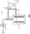
- FIG. 1 shows an exemplary fluid flow system 20.
- the fluid flow system 20 includes a pump element 22 and a filter assembly 24 arranged upstream of the pump element 22.
- a fluid inlet line 28 directs a fluid flow into the filter assembly 24.
- the fluid passes through the filter assembly 24 and exits via a fluid outlet line 30.
- a pressure sensor system 26 is utilized to measure the pressure drop across the filter assembly 24.
- the pressure sensor system 26 may include a delta pressure sensor or an absolute pressure sensor, for example.
- An absolute pressure sensor detects the pressure at a particular point in the system 20.
- a delta pressure sensor senses pressure difference between the fluid flow upstream of the filter assembly 24 and downstream of the filter assembly 24.
- the pressure sensor system 26 may be located remote from the filter assembly 24. Sense lines connect the pressure sensor system 26 to the fluid they are measuring.
- the remote location of the pressure sensor system 26 may allow easier accessibility to the sensors for ease of maintenance and/or replacement.
- the pressure sensor system 26 may send electronic signals to a controller 34 via a wiring harness 32.
- the controller 34 may be an electronic engine control (EEC), for example.
- the fluid flow system 20 may be a fuel system for a gas turbine engine, for example.
- the fluid is fuel that flows from a fuel tank 36 through the filter element 24 and pump element 22 and into an engine 38.
- the engine may be a gas turbine engine, for example.
- Gas turbine engines are known, and may generally include a fan section, a compressor section, a combustor section and a turbine section, among other components.
- the gas turbine engine may be, for example, a two-spool turbofan gas turbine engine, a three-spool architecture, a direct drive turbofan (or turbojet), a geared drive turbofan, an industrial gas turbine (IGT), or any gas turbine engine as desired.
- the present application is not limited to use in conjunction with a specific type of fluid flow system.
- the present application is, for convenience of explanation, depicted and described as being implemented as a gear pump in a lubrication oil system, the present disclosure may be utilized elsewhere in a gas turbine engine, such as a centrifugal pump, or a positive displacement pump in a fuel system. This disclosure may also be implemented in numerous other machines having fluid flow systems.
- FIG. 2 illustrates an example pressure sensor system 26.
- the pressure sensor system 26 detects the pressure of a fluid 40 flowing through a manifold 42.
- the sensor system 26 includes a first sensor 60 and a second sensor 62 arranged in a housing 44.
- the first and second sensors 60, 62 are shown in the same housing, in other examples, the first and second sensors 60, 62 may be arranged in separate housings.
- the first and second sensors 60, 62 are absolute pressure sensors.
- the first and second sensors 60, 62 are delta or differential pressure sensors.
- the first sensor 60 is arranged along a first sense line 46 that is in fluid communication with the manifold 42.
- the second sensor 62 is arranged along a second sense line 48 that is in fluid communication with the manifold 42.
- O-rings 45 are used to seal the juncture between the manifold 42 and the first and second sense lines 46, 48.
- the first and second sensors 60, 62 are in communication with a connector 50 via a first and second wire harness 52, 54, respectively.
- the connector 50 may send data from the first and second sensors 60, 62 to the controller 34, for example.
- Pressure oscillations in the fluid 40 may result in inaccurate pressure readings in the pressure sensors 60, 62, particularly when the pressure oscillations hit the resonant frequency of the sense line 46, 48.
- a shaft speed of the pump element 22 will set the forcing frequency of the pressure ripple.
- the sensor system 26 may monitor the fluid system 20 over a large range of pump element operating speeds, and thus the pressure ripples may vary in frequency.
- the first and second pressure sensors 60, 62 are arranged along first and second sense lines 46, 48.
- the first and second sense lines 46, 48 are in communication with the manifold 42 and communicate the fluid 40 to the first and second pressure sensors 60, 62.
- the first and second sense lines 46, 48 are designed to have different resonant frequencies. Resonant frequency of flow past an orifice depends on the length and hydraulic diameter of the sense line 46, 48, and the volume of fluid within the sense line.
- the first sense line 46 has a first length L 1 and a first hydraulic diameter D 1 , giving it a first resonant frequency.
- the second sense line 48 has a second length L 2 and a second hydraulic diameter D 2 , giving it a second resonant frequency.
- the first resonant frequency is different than the second resonant frequency.
- the first and second lengths L 1 , L 2 are different from one another.
- the first and second hydraulic diameters D 1 , D 2 are different from one another.
- both the length L 1 and hydraulic diameter D 1 of the first sense line 46 are different from the length L 2 and hydraulic diameter D 2 of the second sense line 48.
- the unique resonant frequencies of the first and second sense lines 46, 48 avoid simultaneous resonance in both sensors 60, 62.
- the first sensor 60 may provide erroneous signals when the first sense line 46 is in resonance, but the second sensor 62 should provide an accurate signal at that time.
- the second sensor 62 may provide erroneous signals when the second sense line 48 is in resonance, but the first sensor 60 should provide an accurate signal then.
- the sensors 60, 62 provide a clean pressure signal at all times.
- the first resonance is at least twice the second resonance. This separation of resonances avoids overlapping resonant signals.
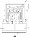
- Figure 3 illustrates another example pressure sensor system 126.
- the manifold 142 includes an upstream portion 140 and a downstream portion 141.
- the upstream portion 140 is upstream of the filter element 24, while the downstream portion 141 is downstream of the filter element 24.
- the sensor system 126 includes a first pressure sensor 160 arranged along a first sense line 146, a second pressure sensor 162 arranged along a second sense line 148, and a third pressure sensor 164 arranged along a third sense line 149.
- Each of the first, second, and third sensors 160, 162, 164 is a differential pressure sensor, and is fluidly connected to the upstream portion 140 and the downstream portion 141.
- Upstream sense lines 146, 148, 149 fluidly connect the first, second, and third sensors 160, 162, 164 to the upstream portion 140.
- Downstream sense lines 147, 151, 153 fluidly connect the first, second, and third sensors 160, 162, 164 to the downstream portion 141.
- the sensors 160, 162, 164 thus detect a difference in pressure between the upstream and downstream portions 140, 141.
- Each of the first, second, and third sensors 160, 162, 164 is in communication with the connector 150 via a wire harness 152, 154, 156, respectively.
- Each of the upstream and downstream sense lines 146, 148, 149, 147, 151, 153 has a different resonant frequency.
- the sense lines 146, 148, 149, 147, 151, 153 each have a different length.
- the sense lines 146, 148, 149, 147, 151, 153 each have a different diameter.
- the sense lines 146, 148, 149, 147, 151, 153 have the same diameter but different lengths, or have the same length but different diameters.
- the different lengths and/or diameters of the sense lines 146, 148, 149, 147, 151, 153 provides a different resonant frequency for each sense line.
- This configuration with three sensors 160, 162, 164 along different sense lines ensures that there will always be a clean signal from at least two of the sensors 160, 162, 164.
- the pump element 22 When the pump element 22 is operating at a shaft speed causing resonance in one of the sensors 160, 162, 164, the other two sensors will still provide a useful signal.
- This arrangement may be beneficial in case one of the three sensors fails, as there will still be a useful signal.
- an exemplary sensor system 26 utilizes two absolute pressure sensors, the system 26 could instead use three or more absolute pressure sensors.
- the exemplary sensor system 126 utilizes three differential pressure sensors, the system 126 could instead use two differential pressure sensors or more than three differential pressure sensors.
- Each of the sensors 60, 62, 160, 162, 164 is connected to a connector 50, 150.
- the connector 50, 150 may be in communication with the controller 34, for example.
- the controller 34 may be an Engine Indicating and Crew Alerting System (EICAS) or an Engine Centralized Aircraft Monitor (ECAM), for example.
- the controller 34 may send a signal to an operator or maintenance crew when any of the sensors 60, 62, 160, 162, 164 has failed.
- the controller 34 is configured to automatically alert a ground maintenance crew of impending maintenance or replacement of components within the fluid system 20 when the aircraft is on the ground.
- the sense lines 46, 48, 146, 148, 149 can be mapped. In one example, the sense lines 46, 48, 146, 148, 149 are selected based on the frequencies of pressure ripples over the entire operating speed range of the pump element 22. In another example, after the sense lines 46, 48, 146, 148, 149 are arranged, the controller 34 determines the behavior of each of the sense lines 46, 48, 146, 148, 149 over the operating speed range of the pump element 22, so that which sense lines 46, 48, 146, 148, 149 are in resonance at particular times is predictable. The controller 36 may then store this information, for example.
Landscapes
- Physics & Mathematics (AREA)
- General Physics & Mathematics (AREA)
- Fluid Mechanics (AREA)
- Measuring Fluid Pressure (AREA)
Abstract
Description
- This disclosure relates to fluid flow systems, and more particularly to pressure sensors for fluid flow systems.
- Aircraft fuel and oil systems typically incorporate external gear pumps. Often, fluid systems include a filtration system to remove contaminants from the fluid flow that could damage fluid system components. Such a filtration system may incorporate a filter that acts as a barrier to collect any contaminants. Typically, pressure sensors are placed in such fluid systems for system health monitoring and scheduling of fluid system component maintenance. Some known systems include multiple pressure sensors along a sense line for redundancy.
- External gear pumps may be the source of pressure ripples, that is, oscillations generated by the periodic meshing and unmeshing of the teeth of the external gear pump. These oscillations create pressure ripples within the fluid in such fluid flow systems. Pressure ripples in the fluid flow may result in an inaccurate pressure reading at the pressure sensors.
- In one exemplary embodiment, a fluid flow arrangement includes a manifold defining a fluid passage. A pressure sensor system is in fluid communication with the fluid passage. The pressure sensor system has a first sensor arranged along a first sense line and a second sensor arranged along a second sense line. The first and second sense lines are in fluid communication with the fluid passage. The first sense line has a first resonant frequency and the second sense line has a second resonant frequency. The second resonant frequency is different than the first resonant frequency.
- In a further embodiment of any of the above, the fluid flow arrangement is a gear pump.
- In a further embodiment of any of the above, the pressure sensors are configured to measure a pressure drop across a filter element.
- In a further embodiment of any of the above, the first sense line has a different hydraulic diameter than the second sense line.
- In a further embodiment of any of the above, the first sense line has a different length than the second sense line.
- In a further embodiment of any of the above, the first sense line has a different length than the second sense line.
- In a further embodiment of any of the above, the second resonant frequency is at least twice the first resonant frequency.
- In a further embodiment of any of the above, a third sense line is arranged within the arrangement. The third sense line has a third resonant frequency that is different than the first and second resonant frequencies.
- In a further embodiment of any of the above, a signal from each of the first and second pressure sensors is sent to a controller.
- In another exemplary embodiment, a fluid flow assembly includes a manifold that defines a fluid passage. A pump element is in fluid communication with the fluid passage. A filter element is in fluid communication with the fluid passage upstream of the pump element. A pressure sensor system is in fluid communication with the fluid passage near the filter element. The pressure sensor system has a first sensor that is arranged along a first sense line and a second sensor arranged along a second sense line. The first and second sense lines are in fluid communication with the fluid passage. The first sense line has a first resonant frequency and the second sense line has a second resonant frequency. The second resonant frequency is different than the first resonant frequency.
- In a further embodiment of any of the above, the first sense line has a different hydraulic diameter than the second sense line.
- In a further embodiment of any of the above, the first sense line has a different length than the second sense line.
- In a further embodiment of any of the above, the second resonant frequency is at least twice the first resonant frequency.
- In a further embodiment of any of the above, a third sense line is arranged within the assembly. The third sense line has a third resonant frequency that is different than the first and second resonant frequencies.
- In another exemplary embodiment, a method of making a fluid passage pressure sensing arrangement includes fluidically coupling a first pressure sensor to a fluid passage of a manifold via a first sense line. A second pressure sensor is fluidically coupled to the fluid passage via a second sense line. The first sense line is tuned to have a first resonant frequency and the second sense line is tuned to have a second resonant frequency. The first resonant frequency is different than the second resonant frequency.
- In a further embodiment of any of the above, the manifold is arranged in a fuel pump that has a geared pump element.
- In a further embodiment of any of the above, a signal is sent from each of the first and second pressure sensors to a controller.
- In a further embodiment of any of the above, the first and second pressure sensors are absolute pressure sensors.
- In a further embodiment of any of the above, the first and second pressure sensors are differential pressure sensors.
- In a further embodiment of any of the above, the tuning step comprises selecting a first length of the first sense line that is different than a second length of the second sense line.
- The disclosure can be further understood by reference to the following detailed description when considered in connection with the accompanying drawings.
-
Figure 1 is a schematic view of an exemplary fluid flow system -
Figure 2 is a schematic view of an example pressure sensor system. -
Figure 3 is a schematic view of another example pressure sensor system. -
Figure 1 shows an exemplaryfluid flow system 20. Thefluid flow system 20 includes apump element 22 and afilter assembly 24 arranged upstream of thepump element 22. Afluid inlet line 28 directs a fluid flow into thefilter assembly 24. The fluid passes through thefilter assembly 24 and exits via afluid outlet line 30. Apressure sensor system 26 is utilized to measure the pressure drop across thefilter assembly 24. Thepressure sensor system 26 may include a delta pressure sensor or an absolute pressure sensor, for example. An absolute pressure sensor detects the pressure at a particular point in thesystem 20. A delta pressure sensor senses pressure difference between the fluid flow upstream of thefilter assembly 24 and downstream of thefilter assembly 24. Thepressure sensor system 26 may be located remote from thefilter assembly 24. Sense lines connect thepressure sensor system 26 to the fluid they are measuring. The remote location of thepressure sensor system 26 may allow easier accessibility to the sensors for ease of maintenance and/or replacement. In some examples, thepressure sensor system 26 may send electronic signals to acontroller 34 via awiring harness 32. Thecontroller 34 may be an electronic engine control (EEC), for example. - The
fluid flow system 20 may be a fuel system for a gas turbine engine, for example. In this example, the fluid is fuel that flows from afuel tank 36 through thefilter element 24 andpump element 22 and into anengine 38. The engine may be a gas turbine engine, for example. Gas turbine engines are known, and may generally include a fan section, a compressor section, a combustor section and a turbine section, among other components. The gas turbine engine may be, for example, a two-spool turbofan gas turbine engine, a three-spool architecture, a direct drive turbofan (or turbojet), a geared drive turbofan, an industrial gas turbine (IGT), or any gas turbine engine as desired. - It should be appreciated that the present application is not limited to use in conjunction with a specific type of fluid flow system. Thus, although the present application is, for convenience of explanation, depicted and described as being implemented as a gear pump in a lubrication oil system, the present disclosure may be utilized elsewhere in a gas turbine engine, such as a centrifugal pump, or a positive displacement pump in a fuel system. This disclosure may also be implemented in numerous other machines having fluid flow systems.
-
Figure 2 illustrates an examplepressure sensor system 26. Thepressure sensor system 26 detects the pressure of a fluid 40 flowing through a manifold 42. Thesensor system 26 includes afirst sensor 60 and asecond sensor 62 arranged in a housing 44. Although the first andsecond sensors second sensors second sensors second sensors first sensor 60 is arranged along afirst sense line 46 that is in fluid communication with the manifold 42. Thesecond sensor 62 is arranged along asecond sense line 48 that is in fluid communication with the manifold 42. In one example, O-rings 45 are used to seal the juncture between the manifold 42 and the first and second sense lines 46, 48. The first andsecond sensors connector 50 via a first andsecond wire harness connector 50 may send data from the first andsecond sensors controller 34, for example. - Pressure oscillations in the fluid 40, such as from the
pump element 22, may result in inaccurate pressure readings in thepressure sensors sense line pump element 22 will set the forcing frequency of the pressure ripple. Thus, depending on engine speed, and pump shaft speed, the pressure ripple frequency will change during operation. Thesensor system 26 may monitor thefluid system 20 over a large range of pump element operating speeds, and thus the pressure ripples may vary in frequency. - In this disclosed system, the first and
second pressure sensors second pressure sensors sense line sensor system 26, thefirst sense line 46 has a first length L1 and a first hydraulic diameter D1, giving it a first resonant frequency. Thesecond sense line 48 has a second length L2 and a second hydraulic diameter D2, giving it a second resonant frequency. The first resonant frequency is different than the second resonant frequency. In some examples, the first and second lengths L1, L2 are different from one another. In other examples, the first and second hydraulic diameters D1, D2 are different from one another. In other examples, both the length L1 and hydraulic diameter D1 of thefirst sense line 46 are different from the length L2 and hydraulic diameter D2 of thesecond sense line 48. - The unique resonant frequencies of the first and second sense lines 46, 48 avoid simultaneous resonance in both
sensors first sensor 60 may provide erroneous signals when thefirst sense line 46 is in resonance, but thesecond sensor 62 should provide an accurate signal at that time. Thesecond sensor 62 may provide erroneous signals when thesecond sense line 48 is in resonance, but thefirst sensor 60 should provide an accurate signal then. Thus, thesensors -
Figure 3 illustrates another examplepressure sensor system 126. In thisexample system 126, the manifold 142 includes anupstream portion 140 and adownstream portion 141. In some examples, theupstream portion 140 is upstream of thefilter element 24, while thedownstream portion 141 is downstream of thefilter element 24. Thesensor system 126 includes a first pressure sensor 160 arranged along afirst sense line 146, asecond pressure sensor 162 arranged along asecond sense line 148, and athird pressure sensor 164 arranged along athird sense line 149. Each of the first, second, andthird sensors upstream portion 140 and thedownstream portion 141. Upstream sense lines 146, 148, 149 fluidly connect the first, second, andthird sensors upstream portion 140. Downstream sense lines 147, 151, 153 fluidly connect the first, second, andthird sensors downstream portion 141. Thesensors downstream portions third sensors connector 150 via awire harness - Each of the upstream and
downstream sense lines - This configuration with three
sensors sensors pump element 22 is operating at a shaft speed causing resonance in one of thesensors - Although an
exemplary sensor system 26 utilizes two absolute pressure sensors, thesystem 26 could instead use three or more absolute pressure sensors. Although theexemplary sensor system 126 utilizes three differential pressure sensors, thesystem 126 could instead use two differential pressure sensors or more than three differential pressure sensors. - Each of the
sensors connector connector controller 34, for example. Thecontroller 34 may be an Engine Indicating and Crew Alerting System (EICAS) or an Engine Centralized Aircraft Monitor (ECAM), for example. Thecontroller 34 may send a signal to an operator or maintenance crew when any of thesensors controller 34 is configured to automatically alert a ground maintenance crew of impending maintenance or replacement of components within thefluid system 20 when the aircraft is on the ground. - In some examples, the sense lines 46, 48, 146, 148, 149 can be mapped. In one example, the sense lines 46, 48, 146, 148, 149 are selected based on the frequencies of pressure ripples over the entire operating speed range of the
pump element 22. In another example, after the sense lines 46, 48, 146, 148, 149 are arranged, thecontroller 34 determines the behavior of each of the sense lines 46, 48, 146, 148, 149 over the operating speed range of thepump element 22, so that which senselines controller 36 may then store this information, for example. - The foregoing description shall be interpreted as illustrative and not in any limiting sense. A worker of ordinary skill in the art would understand that certain modifications could come within the scope of this disclosure. For these reasons, the following claims should be studied to determine the true scope and content of this disclosure.
Claims (15)
- A fluid flow arrangement, comprising:a manifold (142) defining a fluid passage;a pressure sensor system (26) in fluid communication with the fluid passage, the pressure sensor system having a first sensor (160) arranged along a first sense line (146) and a second sensor (162) arranged along a second sense line (148), the first and second sense lines in fluid communication with the fluid passage, the first sense line having a first resonant frequency, and the second sense line having a second resonant frequency, the second resonant frequency being different than the first resonant frequency.
- The fluid flow arrangement of claim 1, wherein the fluid flow arrangement is a gear pump.
- The fluid flow arrangement of claim 1 or 2, wherein the pressure sensors are configured to measure a pressure drop across a filter element.
- The fluid flow arrangement of any preceding claim, wherein the first sense line has a different hydraulic diameter than the second sense line.
- The fluid flow arrangement of claim 4, wherein the first sense line has a different length than the second sense line.
- The fluid flow arrangement of any preceding claim, wherein the first sense line has a different length than the second sense line.
- The fluid flow arrangement of any preceding claim, wherein the second resonant frequency is at least twice the first resonant frequency.
- The fluid flow arrangement of any preceding claim, wherein a third sense line is arranged within the arrangement, the third sense line having a third resonant frequency that is different than the first and second resonant frequencies.
- The fluid flow arrangement of any preceding claim, wherein a signal from each of the first and second pressure sensors is sent to a controller.
- A fluid flow assembly, comprising the fluid flow arrangement of any preceding claim and further comprising
a pump element in fluid communication with the fluid passage;
a filter element in fluid communication with the fluid passage upstream of the pump element; and
the pressure sensor system being in fluid communication with the fluid passage near the filter element. - A method of making a fluid passage pressure sensing arrangement, comprising:fluidically coupling a first pressure sensor to a fluid passage of a manifold via a first sense line;fluidically coupling a second pressure sensor to the fluid passage via a second sense line; andtuning the first sense line to have a first resonant frequency and the second sense line to have a second resonant frequency, the first resonant frequency being different than the second resonant frequency.
- The method of making a fluid passage pressure sensing arrangement of claim 11, wherein the manifold is arranged in a fuel pump having a geared pump element.
- The method of making a fluid passage pressure sensing arrangement of claim 11 or 12, comprising sending a signal from each of the first and second pressure sensors to a controller.
- The method of making a fluid passage pressure sensing arrangement of any of claims 11 to 13, wherein the first and second pressure sensors are absolute pressure sensors, or
wherein the first and second pressure sensors are differential pressure sensors. - The method of making a fluid passage pressure sensing arrangement of any of claims 11 to 14, wherein the tuning step comprises selecting a first length of the first sense line that is different than a second length of the second sense line.
Applications Claiming Priority (1)
| Application Number | Priority Date | Filing Date | Title |
|---|---|---|---|
| US16/656,926 US11619560B2 (en) | 2019-10-18 | 2019-10-18 | Pressure ripple mitigation in pressure sensors |
Publications (2)
| Publication Number | Publication Date |
|---|---|
| EP3809106A1 true EP3809106A1 (en) | 2021-04-21 |
| EP3809106B1 EP3809106B1 (en) | 2022-11-16 |
Family
ID=68887285
Family Applications (1)
| Application Number | Title | Priority Date | Filing Date |
|---|---|---|---|
| EP19215566.1A Active EP3809106B1 (en) | 2019-10-18 | 2019-12-12 | Pressure ripple mitigation in pressure sensors |
Country Status (2)
| Country | Link |
|---|---|
| US (1) | US11619560B2 (en) |
| EP (1) | EP3809106B1 (en) |
Families Citing this family (8)
| Publication number | Priority date | Publication date | Assignee | Title |
|---|---|---|---|---|
| WO2019027771A1 (en) * | 2017-07-31 | 2019-02-07 | Precision Planting Llc | Pressure measurement module |
| US11767722B2 (en) * | 2019-02-07 | 2023-09-26 | Detechtion Usa Inc. | Chemical treatment tank level sensor |
| US12085022B2 (en) * | 2019-10-07 | 2024-09-10 | Pratt & Whitney Canada Corp. | Aircraft fluid system pressure variation attenuation |
| US11767837B2 (en) * | 2019-11-14 | 2023-09-26 | Vanair Manufacturing, Inc. | Compressor control systems and air compressor systems and vehicles equipped therewith |
| US11608927B2 (en) | 2020-07-24 | 2023-03-21 | Pratt & Whitney Canada Corp | Hydraulic snubber insert for gas turbine engine and associated method of installation |
| CN113776725B (en) * | 2021-08-12 | 2024-05-24 | 中国船舶重工集团公司第七一九研究所 | Remote pressure measuring device |
| US20240003376A1 (en) * | 2022-06-29 | 2024-01-04 | Hamilton Sundstrand Corporation | Manifold with repairable thread insert assemblies within manifold boreholes |
| WO2025071888A1 (en) * | 2023-09-26 | 2025-04-03 | Championx Llc | Pump inlet pressure stabilizer for measuring storage tank liquid level using pressure measurement |
Citations (2)
| Publication number | Priority date | Publication date | Assignee | Title |
|---|---|---|---|---|
| EP2442085A1 (en) * | 2010-10-14 | 2012-04-18 | Rolls-Royce plc | Presure indicator with means for minimizing resonance frequencies |
| US20130319103A1 (en) * | 2012-06-04 | 2013-12-05 | Baker Hughes Incorporated | Dual Differential Pressure Multiphase Flow Meter |
Family Cites Families (31)
| Publication number | Priority date | Publication date | Assignee | Title |
|---|---|---|---|---|
| US4314621A (en) | 1979-03-07 | 1982-02-09 | Caterpillar Tractor Co. | Fluidborne noise attenuator |
| US4272368A (en) | 1979-09-04 | 1981-06-09 | Parker-Hannifin Corporation | Fluid filter and indicator |
| US4932205A (en) | 1989-02-27 | 1990-06-12 | Allied-Signal Inc. | Bypass valve and visual indicator for a fuel system |
| US5475976A (en) | 1994-04-29 | 1995-12-19 | Techco Corporation | Method and apparatus for reduction of fluid borne noise in hydraulic systems |
| US5531513A (en) | 1994-12-16 | 1996-07-02 | Kelsey-Hayes | High pressure accumulator/bypass valve with stationary high pressure seal |
| US5588805A (en) | 1995-08-28 | 1996-12-31 | Sauer Inc. | Vibration and pressure attenuator for hydraulic units |
| GB9518582D0 (en) | 1995-09-09 | 1996-09-11 | Lucas Ind Plc | Fuel control system for gas turbine engine |
| US5961309A (en) | 1997-04-24 | 1999-10-05 | Trw Inc. | Gear pump with noise attenuation |
| US6073656A (en) | 1997-11-24 | 2000-06-13 | Dayco Products, Inc. | Energy attenuation device for a conduit conveying liquid under pressure, system incorporating same, and method of attenuating energy in a conduit |
| US6308723B1 (en) | 1998-11-18 | 2001-10-30 | Alliedsignal, Inc. | Piezo-resistive position indicator |
| US6234758B1 (en) | 1999-12-01 | 2001-05-22 | Caterpillar Inc. | Hydraulic noise reduction assembly with variable side branch |
| US7036530B2 (en) | 1999-12-22 | 2006-05-02 | Dayco Products, Llc | Energy attenuation device for a fluid-conveying line and method of attenuating energy in such a line |
| US6401446B1 (en) | 2000-06-23 | 2002-06-11 | Hamilton Sundstrand Corporation | Valve apparatus for providing shutoff and overspeed protection in a gas turbine fuel system |
| US6854269B2 (en) | 2002-07-23 | 2005-02-15 | Caterpillar Inc. | Noise attenuation in a hydraulic circuit |
| DE10316946A1 (en) | 2003-04-12 | 2004-10-21 | Daimlerchrysler Ag | Device and method for damping pressure oscillations in hydraulic lines |
| US7325570B1 (en) | 2004-12-06 | 2008-02-05 | Coupled Products, Llc | Method and apparatus for noise suppression in a fluid line |
| US20070201989A1 (en) | 2005-10-14 | 2007-08-30 | Parker-Hannifin | Low ripple gear pump/motor |
| DE102005058547B4 (en) | 2005-12-08 | 2012-04-12 | Airbus Operations Gmbh | Device for reducing hydrofluidic vibrations in a hydraulic system |
| US7640919B1 (en) | 2008-01-31 | 2010-01-05 | Perkins Engines Company Limited | Fuel system for protecting a fuel filter |
| EP2276936B1 (en) | 2008-04-23 | 2016-11-09 | Actuant Corporation | Hydraulic system with a pressure ripple reduction device |
| US8678780B2 (en) | 2010-02-26 | 2014-03-25 | GM Global Technology Operations LLC | Transmission hydraulic control system having a pump bypass valve |
| US8656772B2 (en) | 2010-03-22 | 2014-02-25 | Honeywell International Inc. | Flow sensor with pressure output signal |
| US8707791B2 (en) | 2010-09-10 | 2014-04-29 | Kulite Semiconductor Products, Inc. | Tunable pressure transducer assembly |
| US9482125B2 (en) | 2010-09-14 | 2016-11-01 | GM Global Technology Operations LLC | Particulate filter and hydrocarbon adsorber bypass systems |
| US20120234770A1 (en) | 2011-01-18 | 2012-09-20 | Goodwin Christopher L | Filter assembly and control system |
| US8739811B2 (en) | 2011-02-07 | 2014-06-03 | Honeywell International Inc. | Direct metering fuel system with constant servo flow |
| US9152151B2 (en) | 2011-04-20 | 2015-10-06 | Tescom Corporation | In-line back pressure fluid regulators |
| EP4450845A3 (en) | 2013-03-15 | 2025-01-01 | ClearMotion, Inc. | Active vehicle suspension improvements |
| US10987617B2 (en) | 2016-04-05 | 2021-04-27 | Hamilton Sundstrand Corporation | Pressure detection system immune to pressure ripple effects |
| EP3396346A1 (en) | 2017-04-27 | 2018-10-31 | Siemens Aktiengesellschaft | Pressure sensor verification device and methods of operation and manufacturing |
| CN109269710B (en) * | 2018-10-31 | 2020-07-21 | 北京建筑大学 | Pressure monitoring system and method for pulsating heat pipe |
-
2019
- 2019-10-18 US US16/656,926 patent/US11619560B2/en active Active
- 2019-12-12 EP EP19215566.1A patent/EP3809106B1/en active Active
Patent Citations (2)
| Publication number | Priority date | Publication date | Assignee | Title |
|---|---|---|---|---|
| EP2442085A1 (en) * | 2010-10-14 | 2012-04-18 | Rolls-Royce plc | Presure indicator with means for minimizing resonance frequencies |
| US20130319103A1 (en) * | 2012-06-04 | 2013-12-05 | Baker Hughes Incorporated | Dual Differential Pressure Multiphase Flow Meter |
Also Published As
| Publication number | Publication date |
|---|---|
| US20210116272A1 (en) | 2021-04-22 |
| US11619560B2 (en) | 2023-04-04 |
| EP3809106B1 (en) | 2022-11-16 |
Similar Documents
| Publication | Publication Date | Title |
|---|---|---|
| US11619560B2 (en) | Pressure ripple mitigation in pressure sensors | |
| EP3044438B1 (en) | Fan drive gear system auxiliary pump monitoring system | |
| US9382849B2 (en) | Control of gas turbine engine | |
| US8152496B2 (en) | Continuing compressor operation through redundant algorithms | |
| US10287935B2 (en) | Virtual filter condition sensor | |
| EP2469368A2 (en) | Method and system for determining a component's resistance to flow | |
| US12085556B2 (en) | Multi-passage oil debris monitor to increase detection capability in high oil flow systems | |
| EP3696535B1 (en) | Active oil debris monitor particle detection and monitoring system | |
| JP2008544131A (en) | Detection of engine status using an external microphone | |
| EP3696543A2 (en) | Active oil debris monitor particle detection and monitoring system | |
| CN111182957A (en) | Disposable filter with accessory port | |
| CN114810232A (en) | System and method for fault sensing flow components | |
| EP3696544A2 (en) | Active oil debris monitor phase angle calculation and monitoring system | |
| EP3228375B1 (en) | Pressure detection system immune to pressure ripple effects | |
| EP3385690B1 (en) | Aircraft fluid control system having a pressure sensor | |
| US11131604B2 (en) | Turbocharger speed sensor diagnostic tool and method | |
| EP3358147B1 (en) | Bypass valve system state indication | |
| JP7349966B2 (en) | Machine lubricating oil supply system monitoring method and device | |
| EP2458179A2 (en) | Method of monitoring an electronic engine control (EEC) to detect fuel screen clogging | |
| Johnston et al. | Condition monitoring of aircraft fuel pumps using pressure ripple measurements |
Legal Events
| Date | Code | Title | Description |
|---|---|---|---|
| PUAI | Public reference made under article 153(3) epc to a published international application that has entered the european phase |
Free format text: ORIGINAL CODE: 0009012 |
|
| STAA | Information on the status of an ep patent application or granted ep patent |
Free format text: STATUS: THE APPLICATION HAS BEEN PUBLISHED |
|
| AK | Designated contracting states |
Kind code of ref document: A1 Designated state(s): AL AT BE BG CH CY CZ DE DK EE ES FI FR GB GR HR HU IE IS IT LI LT LU LV MC MK MT NL NO PL PT RO RS SE SI SK SM TR |
|
| AX | Request for extension of the european patent |
Extension state: BA ME |
|
| STAA | Information on the status of an ep patent application or granted ep patent |
Free format text: STATUS: REQUEST FOR EXAMINATION WAS MADE |
|
| 17P | Request for examination filed |
Effective date: 20211018 |
|
| RBV | Designated contracting states (corrected) |
Designated state(s): AL AT BE BG CH CY CZ DE DK EE ES FI FR GB GR HR HU IE IS IT LI LT LU LV MC MK MT NL NO PL PT RO RS SE SI SK SM TR |
|
| GRAP | Despatch of communication of intention to grant a patent |
Free format text: ORIGINAL CODE: EPIDOSNIGR1 |
|
| STAA | Information on the status of an ep patent application or granted ep patent |
Free format text: STATUS: GRANT OF PATENT IS INTENDED |
|
| RIC1 | Information provided on ipc code assigned before grant |
Ipc: G01L 19/00 20060101AFI20220513BHEP |
|
| INTG | Intention to grant announced |
Effective date: 20220601 |
|
| GRAS | Grant fee paid |
Free format text: ORIGINAL CODE: EPIDOSNIGR3 |
|
| GRAA | (expected) grant |
Free format text: ORIGINAL CODE: 0009210 |
|
| STAA | Information on the status of an ep patent application or granted ep patent |
Free format text: STATUS: THE PATENT HAS BEEN GRANTED |
|
| AK | Designated contracting states |
Kind code of ref document: B1 Designated state(s): AL AT BE BG CH CY CZ DE DK EE ES FI FR GB GR HR HU IE IS IT LI LT LU LV MC MK MT NL NO PL PT RO RS SE SI SK SM TR |
|
| REG | Reference to a national code |
Ref country code: GB Ref legal event code: FG4D |
|
| REG | Reference to a national code |
Ref country code: CH Ref legal event code: EP |
|
| REG | Reference to a national code |
Ref country code: IE Ref legal event code: FG4D |
|
| REG | Reference to a national code |
Ref country code: DE Ref legal event code: R096 Ref document number: 602019021941 Country of ref document: DE |
|
| REG | Reference to a national code |
Ref country code: AT Ref legal event code: REF Ref document number: 1532027 Country of ref document: AT Kind code of ref document: T Effective date: 20221215 |
|
| REG | Reference to a national code |
Ref country code: LT Ref legal event code: MG9D |
|
| REG | Reference to a national code |
Ref country code: NL Ref legal event code: MP Effective date: 20221116 |
|
| REG | Reference to a national code |
Ref country code: AT Ref legal event code: MK05 Ref document number: 1532027 Country of ref document: AT Kind code of ref document: T Effective date: 20221116 |
|
| PG25 | Lapsed in a contracting state [announced via postgrant information from national office to epo] |
Ref country code: SE Free format text: LAPSE BECAUSE OF FAILURE TO SUBMIT A TRANSLATION OF THE DESCRIPTION OR TO PAY THE FEE WITHIN THE PRESCRIBED TIME-LIMIT Effective date: 20221116 Ref country code: PT Free format text: LAPSE BECAUSE OF FAILURE TO SUBMIT A TRANSLATION OF THE DESCRIPTION OR TO PAY THE FEE WITHIN THE PRESCRIBED TIME-LIMIT Effective date: 20230316 Ref country code: NO Free format text: LAPSE BECAUSE OF FAILURE TO SUBMIT A TRANSLATION OF THE DESCRIPTION OR TO PAY THE FEE WITHIN THE PRESCRIBED TIME-LIMIT Effective date: 20230216 Ref country code: LT Free format text: LAPSE BECAUSE OF FAILURE TO SUBMIT A TRANSLATION OF THE DESCRIPTION OR TO PAY THE FEE WITHIN THE PRESCRIBED TIME-LIMIT Effective date: 20221116 Ref country code: FI Free format text: LAPSE BECAUSE OF FAILURE TO SUBMIT A TRANSLATION OF THE DESCRIPTION OR TO PAY THE FEE WITHIN THE PRESCRIBED TIME-LIMIT Effective date: 20221116 Ref country code: ES Free format text: LAPSE BECAUSE OF FAILURE TO SUBMIT A TRANSLATION OF THE DESCRIPTION OR TO PAY THE FEE WITHIN THE PRESCRIBED TIME-LIMIT Effective date: 20221116 Ref country code: AT Free format text: LAPSE BECAUSE OF FAILURE TO SUBMIT A TRANSLATION OF THE DESCRIPTION OR TO PAY THE FEE WITHIN THE PRESCRIBED TIME-LIMIT Effective date: 20221116 |
|
| PG25 | Lapsed in a contracting state [announced via postgrant information from national office to epo] |
Ref country code: RS Free format text: LAPSE BECAUSE OF FAILURE TO SUBMIT A TRANSLATION OF THE DESCRIPTION OR TO PAY THE FEE WITHIN THE PRESCRIBED TIME-LIMIT Effective date: 20221116 Ref country code: PL Free format text: LAPSE BECAUSE OF FAILURE TO SUBMIT A TRANSLATION OF THE DESCRIPTION OR TO PAY THE FEE WITHIN THE PRESCRIBED TIME-LIMIT Effective date: 20221116 Ref country code: LV Free format text: LAPSE BECAUSE OF FAILURE TO SUBMIT A TRANSLATION OF THE DESCRIPTION OR TO PAY THE FEE WITHIN THE PRESCRIBED TIME-LIMIT Effective date: 20221116 Ref country code: IS Free format text: LAPSE BECAUSE OF FAILURE TO SUBMIT A TRANSLATION OF THE DESCRIPTION OR TO PAY THE FEE WITHIN THE PRESCRIBED TIME-LIMIT Effective date: 20230316 Ref country code: HR Free format text: LAPSE BECAUSE OF FAILURE TO SUBMIT A TRANSLATION OF THE DESCRIPTION OR TO PAY THE FEE WITHIN THE PRESCRIBED TIME-LIMIT Effective date: 20221116 Ref country code: GR Free format text: LAPSE BECAUSE OF FAILURE TO SUBMIT A TRANSLATION OF THE DESCRIPTION OR TO PAY THE FEE WITHIN THE PRESCRIBED TIME-LIMIT Effective date: 20230217 |
|
| PG25 | Lapsed in a contracting state [announced via postgrant information from national office to epo] |
Ref country code: NL Free format text: LAPSE BECAUSE OF FAILURE TO SUBMIT A TRANSLATION OF THE DESCRIPTION OR TO PAY THE FEE WITHIN THE PRESCRIBED TIME-LIMIT Effective date: 20221116 |
|
| P01 | Opt-out of the competence of the unified patent court (upc) registered |
Effective date: 20230603 |
|
| PG25 | Lapsed in a contracting state [announced via postgrant information from national office to epo] |
Ref country code: SM Free format text: LAPSE BECAUSE OF FAILURE TO SUBMIT A TRANSLATION OF THE DESCRIPTION OR TO PAY THE FEE WITHIN THE PRESCRIBED TIME-LIMIT Effective date: 20221116 Ref country code: RO Free format text: LAPSE BECAUSE OF FAILURE TO SUBMIT A TRANSLATION OF THE DESCRIPTION OR TO PAY THE FEE WITHIN THE PRESCRIBED TIME-LIMIT Effective date: 20221116 Ref country code: EE Free format text: LAPSE BECAUSE OF FAILURE TO SUBMIT A TRANSLATION OF THE DESCRIPTION OR TO PAY THE FEE WITHIN THE PRESCRIBED TIME-LIMIT Effective date: 20221116 Ref country code: DK Free format text: LAPSE BECAUSE OF FAILURE TO SUBMIT A TRANSLATION OF THE DESCRIPTION OR TO PAY THE FEE WITHIN THE PRESCRIBED TIME-LIMIT Effective date: 20221116 Ref country code: CZ Free format text: LAPSE BECAUSE OF FAILURE TO SUBMIT A TRANSLATION OF THE DESCRIPTION OR TO PAY THE FEE WITHIN THE PRESCRIBED TIME-LIMIT Effective date: 20221116 |
|
| REG | Reference to a national code |
Ref country code: CH Ref legal event code: PL |
|
| REG | Reference to a national code |
Ref country code: DE Ref legal event code: R097 Ref document number: 602019021941 Country of ref document: DE |
|
| REG | Reference to a national code |
Ref country code: BE Ref legal event code: MM Effective date: 20221231 |
|
| PG25 | Lapsed in a contracting state [announced via postgrant information from national office to epo] |
Ref country code: SK Free format text: LAPSE BECAUSE OF FAILURE TO SUBMIT A TRANSLATION OF THE DESCRIPTION OR TO PAY THE FEE WITHIN THE PRESCRIBED TIME-LIMIT Effective date: 20221116 Ref country code: LU Free format text: LAPSE BECAUSE OF NON-PAYMENT OF DUE FEES Effective date: 20221212 Ref country code: AL Free format text: LAPSE BECAUSE OF FAILURE TO SUBMIT A TRANSLATION OF THE DESCRIPTION OR TO PAY THE FEE WITHIN THE PRESCRIBED TIME-LIMIT Effective date: 20221116 |
|
| PLBE | No opposition filed within time limit |
Free format text: ORIGINAL CODE: 0009261 |
|
| STAA | Information on the status of an ep patent application or granted ep patent |
Free format text: STATUS: NO OPPOSITION FILED WITHIN TIME LIMIT |
|
| 26N | No opposition filed |
Effective date: 20230817 |
|
| PG25 | Lapsed in a contracting state [announced via postgrant information from national office to epo] |
Ref country code: LI Free format text: LAPSE BECAUSE OF NON-PAYMENT OF DUE FEES Effective date: 20221231 Ref country code: IE Free format text: LAPSE BECAUSE OF NON-PAYMENT OF DUE FEES Effective date: 20221212 Ref country code: CH Free format text: LAPSE BECAUSE OF NON-PAYMENT OF DUE FEES Effective date: 20221231 |
|
| PG25 | Lapsed in a contracting state [announced via postgrant information from national office to epo] |
Ref country code: SI Free format text: LAPSE BECAUSE OF FAILURE TO SUBMIT A TRANSLATION OF THE DESCRIPTION OR TO PAY THE FEE WITHIN THE PRESCRIBED TIME-LIMIT Effective date: 20221116 Ref country code: BE Free format text: LAPSE BECAUSE OF NON-PAYMENT OF DUE FEES Effective date: 20221231 |
|
| PG25 | Lapsed in a contracting state [announced via postgrant information from national office to epo] |
Ref country code: CY Free format text: LAPSE BECAUSE OF FAILURE TO SUBMIT A TRANSLATION OF THE DESCRIPTION OR TO PAY THE FEE WITHIN THE PRESCRIBED TIME-LIMIT Effective date: 20221116 |
|
| PG25 | Lapsed in a contracting state [announced via postgrant information from national office to epo] |
Ref country code: MK Free format text: LAPSE BECAUSE OF FAILURE TO SUBMIT A TRANSLATION OF THE DESCRIPTION OR TO PAY THE FEE WITHIN THE PRESCRIBED TIME-LIMIT Effective date: 20221116 Ref country code: IT Free format text: LAPSE BECAUSE OF FAILURE TO SUBMIT A TRANSLATION OF THE DESCRIPTION OR TO PAY THE FEE WITHIN THE PRESCRIBED TIME-LIMIT Effective date: 20221116 Ref country code: HU Free format text: LAPSE BECAUSE OF FAILURE TO SUBMIT A TRANSLATION OF THE DESCRIPTION OR TO PAY THE FEE WITHIN THE PRESCRIBED TIME-LIMIT; INVALID AB INITIO Effective date: 20191212 |
|
| PG25 | Lapsed in a contracting state [announced via postgrant information from national office to epo] |
Ref country code: MC Free format text: LAPSE BECAUSE OF FAILURE TO SUBMIT A TRANSLATION OF THE DESCRIPTION OR TO PAY THE FEE WITHIN THE PRESCRIBED TIME-LIMIT Effective date: 20221116 |
|
| PG25 | Lapsed in a contracting state [announced via postgrant information from national office to epo] |
Ref country code: MC Free format text: LAPSE BECAUSE OF FAILURE TO SUBMIT A TRANSLATION OF THE DESCRIPTION OR TO PAY THE FEE WITHIN THE PRESCRIBED TIME-LIMIT Effective date: 20221116 |
|
| PG25 | Lapsed in a contracting state [announced via postgrant information from national office to epo] |
Ref country code: BG Free format text: LAPSE BECAUSE OF FAILURE TO SUBMIT A TRANSLATION OF THE DESCRIPTION OR TO PAY THE FEE WITHIN THE PRESCRIBED TIME-LIMIT Effective date: 20221116 |
|
| PG25 | Lapsed in a contracting state [announced via postgrant information from national office to epo] |
Ref country code: MT Free format text: LAPSE BECAUSE OF FAILURE TO SUBMIT A TRANSLATION OF THE DESCRIPTION OR TO PAY THE FEE WITHIN THE PRESCRIBED TIME-LIMIT Effective date: 20221116 |
|
| PG25 | Lapsed in a contracting state [announced via postgrant information from national office to epo] |
Ref country code: TR Free format text: LAPSE BECAUSE OF FAILURE TO SUBMIT A TRANSLATION OF THE DESCRIPTION OR TO PAY THE FEE WITHIN THE PRESCRIBED TIME-LIMIT Effective date: 20221116 |
|
| PGFP | Annual fee paid to national office [announced via postgrant information from national office to epo] |
Ref country code: DE Payment date: 20251126 Year of fee payment: 7 |
|
| PGFP | Annual fee paid to national office [announced via postgrant information from national office to epo] |
Ref country code: GB Payment date: 20251120 Year of fee payment: 7 |
|
| PGFP | Annual fee paid to national office [announced via postgrant information from national office to epo] |
Ref country code: FR Payment date: 20251120 Year of fee payment: 7 |