EP3809077A1 - Refrigerator and assembly method thereof - Google Patents
Refrigerator and assembly method thereof Download PDFInfo
- Publication number
- EP3809077A1 EP3809077A1 EP19202945.2A EP19202945A EP3809077A1 EP 3809077 A1 EP3809077 A1 EP 3809077A1 EP 19202945 A EP19202945 A EP 19202945A EP 3809077 A1 EP3809077 A1 EP 3809077A1
- Authority
- EP
- European Patent Office
- Prior art keywords
- rigid
- slopped
- metal plate
- cabinet
- self
- Prior art date
- Legal status (The legal status is an assumption and is not a legal conclusion. Google has not performed a legal analysis and makes no representation as to the accuracy of the status listed.)
- Granted
Links
Images




Classifications
-
- F—MECHANICAL ENGINEERING; LIGHTING; HEATING; WEAPONS; BLASTING
- F25—REFRIGERATION OR COOLING; COMBINED HEATING AND REFRIGERATION SYSTEMS; HEAT PUMP SYSTEMS; MANUFACTURE OR STORAGE OF ICE; LIQUEFACTION SOLIDIFICATION OF GASES
- F25D—REFRIGERATORS; COLD ROOMS; ICE-BOXES; COOLING OR FREEZING APPARATUS NOT OTHERWISE PROVIDED FOR
- F25D23/00—General constructional features
- F25D23/06—Walls
- F25D23/062—Walls defining a cabinet
- F25D23/063—Walls defining a cabinet formed by an assembly of panels
Definitions
- the present invention relates to a refrigerator and to the assembly method thereof.
- the present invention preferably relates to a household refrigerator for preserving perishable foodstuff, to which the following description will make explicit reference without however losing in generality.
- a household refrigerator generally comprises: a substantially parallelepiped-shaped, self-supporting cabinet which is structured for stably resting on the floor/ground and has at least one, thermal-insulated inner storage cavity that is adapted to accommodate perishable foodstuff and communicates with the outside through a large access opening located on front of the cabinet; at least one sealing door that has a thermal-insulating structure and is flag hinged to the front of the self-supporting cabinet so as to be manually rotatable about a vertical axis to and from a closing position in which the door abuts on front of the cabinet, so as to airtight close the access opening of the storage cavity; and finally an electrically-operated, cooling system which is located inside the cabinet and is structured to keep the inside of the storage cavity at a given temperature suitable for short-term preservation of perishable foodstuffs and generally ranging between +2°C and +6°C.
- the self-supporting cabinet is generally made up of a substantially parallelepiped-shaped, rigid boxlike outer casing that forms the outside of the cabinet; of a substantially tub-shaped, rigid inner shell which is usually made of plastic material, and is stably fitted/recessed into the outer casing so as to form the inside of the self-supporting cabinet and thus delimit the inner storage cavity or cavities of the cabinet; and a thermal-insulating stuffing which is made of hard polymeric-material foam and fills up the interspace between the boxlike outer casing and the inner shell to strengthen the structure and minimize the heat exchange with the outside.
- the outer casing furthermore, basically consists of a number of substantially flat and roughly rectangular-shaped, rigid and platelike panels that are firmly fixed to one another and/or to the beneath-located thermal-insulating stuffing so as to form the outer flat walls of the cabinet.
- the platelike panels forming the horizontal top wall and the two vertical side walls of the cabinet are typically made of metal sheet. Being always hidden, the platelike panels forming the horizontal bottom wall and the vertical rear wall of the cabinet, in turn, basically consist of thick board of plastic material.
- Aim of the present invention is therefore to simplify the assembly of the refrigerator so as to reduce the overall production costs, and to improve, at same time, the fire resistance capabilities of the cabinet while strengthening its structure.
- a refrigerator comprising: a self-supporting cabinet which is structured for stably resting on the floor/ground, has a thermal-insulating structure and is provided with at least one, inner thermal-insulated storage cavity that is adapted to accommodate perishable foodstuff and communicates with the outside via an access opening located on a main face/wall of the cabinet; the self-supporting cabinet, in turn, comprising: a rigid boxlike outer casing that forms the outside of said self-supporting cabinet; a tub-shaped, rigid inner shell which is stably fitted/recessed into the outer casing so as to form the inside of the cabinet and delimits said at-least-one inner storage cavity; and a thermal-insulating stuffing which is interposed between the inner shell and the outer casing to minimize the heat exchange with the outside; the rigid boxlike outer casing including a number of rigid platelike panels that are placed side-by-side to one another and are firmly fixed/attached to one another and/or to the beneath
- the refrigerator is furthermore characterized in that said oblong slopped flap is plastically deformed, over the slopped sidewall of the receiving groove, so as to match the pitch of said slopped sidewall.
- the refrigerator is furthermore characterized in that the rigid supporting frame-work is substantially annular in shape and substantially copies the shape of the perimeter of said metal plate.
- the refrigerator is furthermore characterized in that the rigid supporting frame-work is at least partly integral to one or more of the remaining adjacent platelike panels of said rigid boxlike outer casing.
- the refrigerator is furthermore characterized in that the rigid supporting frame-work includes one or more rigid profile members firmly connected to one or more of the remaining adjacent platelike panels of said rigid boxlike outer casing.
- the refrigerator is furthermore characterized in that said metal plate has at least a pair of outwards-extending and reciprocally diverging, slopped flaps that are located on opposite sides of the same metal plate, and each of which overlaps and stably couples to a slopped sidewall of a respective receiving groove formed on said beneath-located rigid supporting framework.
- the refrigerator is furthermore characterized in that said slopped flap is located on a substantially straight, section of the perimeter edge of said metal plate, and overlaps and stably couples to a slopped sidewall of a substantially straight, receiving groove.
- the refrigerator is furthermore characterized in that said metal plate is substantially rectangular in shape.
- the refrigerator is furthermore characterized in that the metal plate has, on each side, a respective outwards-extending slopped flap.
- the refrigerator is furthermore characterized in that said at least one, slopped flap is rigidly fixed to the beneath-located slopped sidewall by gluing.
- the refrigerator is furthermore characterized in that the preceding claims, wherein the self-supporting cabinet is substantially parallelepiped in shape and the outer casing comprises: a first platelike panel forming the substantially horizontally-oriented top wall of the self-supporting cabinet; a pair of second rigid plate like panels forming the substantially vertically-oriented and reciprocally-faced, opposite side walls of the self-supporting cabinet; a third rigid platelike panel forming the substantially vertically-oriented rear wall of the self-supporting cabinet; and a fourth rigid platelike panel forming the substantially horizontally-oriented bottom wall of the self-supporting cabinet; said first platelike panel and/or said second platelike panel and/or said third platelike panel including said metal plate with at least one outwards-extending slopped flap.
- the refrigerator is furthermore characterized in that the outer casing additionally includes a number of stiffening crossbars that rigidly connect said second platelike panels to one another.
- the refrigerator is furthermore characterized in that said rigid supporting framework is partially incorporated into one of said stiffening crossbars.
- the refrigerator is furthermore characterized in that said receiving groove has a substantially V-shaped or trapezoid-shaped cross-section.
- the refrigerator is furthermore characterized in that said thermal-insulating stuffing is made of polymeric-material foam.
- the refrigerator is furthermore characterized by additionally comprising at least one door which has a thermal-insulating structure and is hinged to the cabinet so as to be able to rotate to and from a closing position in which said door abuts on the cabinet to close the access opening of the storage cavity.
- the refrigerator is furthermore characterized in that said metal plate is made of zinc-plated steel.
- the refrigerator is furthermore characterized by additionally comprising a cooling system which is at least partially accommodated inside said self-supporting cabinet, and is adapted to cool down the inside of said at least one, inner thermal-insulated storage cavity.
- a cooling system which is at least partially accommodated inside said self-supporting cabinet, and is adapted to cool down the inside of said at least one, inner thermal-insulated storage cavity.
- an assembly method of a refrigerator having a self-supporting cabinet which is structured for stably resting on the floor/ground, has a thermal-insulating structure and is provided with at least one, inner thermal-insulated storage cavity that is adapted to accommodate perishable foodstuff and communicates with the outside via an access opening located on a main face/wall of the cabinet;
- the self-supporting cabinet comprising: a rigid boxlike outer casing that forms the outside of said self-supporting cabinet; a tub-shaped, rigid inner shell which is stably fitted/recessed into the outer casing so as to form the inside of the cabinet and delimits said at-least-one inner storage cavity; and a thermal-insulating stuffing which is interposed between the inner shell and the outer casing to minimize the heat exchange with the outside;
- the rigid boxlike outer casing including a number of rigid platelike panels that are placed side-by-side to one another and are firmly fixed/attached to one another and/or to the beneath-located thermal-insulating
- the assembly method is furthermore characterized in that the bending angle of the/each slopped flap of said metal plate with respect to the lying plane of the metal plate is greater than the tilt angle of the corresponding slopped sidewall of the receiving groove with respect to the same lying plane of the metal plate, so that the/each slopped flap is forced to plastically bend/lean backwards when overlapping the corresponding slopped sidewall of the receiving groove.
- the assembly method is furthermore characterized by additionally comprising, before the step of pressing the metal plate against the beneath-located rigid supporting framework, the step of putting an adhesive material between said metal plate and said supporting framework.
- the assembly method is furthermore characterized in that the adhesive material is interposed between said slopped flap/s of the metal plate and the corresponding slopped sidewall of the receiving groove.
- the assembly method is furthermore characterized in that the bending angle of the/each outwards-extending slopped flap of the metal plate with respect to the lying plane of the same metal plate ranges between 60° and 80°.
- the slopped flaps of the panel onto the beneath-located rigid supporting framework greatly simplifies the handling of the outer casing before injection and solidification of the polymeric-material foam that forms the thermal-insulating stuffing of the self-supporting cabinet.
- reference number 1 denotes as a whole a refrigerator adapted for preserving perishable foodstuff and preferably suitable for domestic use, i.e. a household refrigerator.
- Refrigerator 1 basically comprises: a preferably substantially parallelepiped-shaped, self-supporting cabinet 2 which is structured for stably resting on the floor/ ground, has a thermal-insulating structure and is internally provided with at least one, thermal-insulated storage cavity which is adapted to accommodate perishable foodstuff and communicates with the outside via a large, preferably roughly rectangular-shaped, access opening which is located on a main face/wall of the same cabinet 2; at least one sealing door that has a thermal-insulating structure and is flag hinged to the cabinet 2, so as to be manually rotatable to and from a closing position in which the door abuts on said main face/wall of cabinet 2 to substantially airtight close the access opening of said storage cavity; and an electrically-operated, cooling system which is at least partially accommodated inside the cabinet 2, and is structured/adapted to cool down the inside of said inner storage cavity.
- the access opening of said at-least-one inner storage cavity is preferably located on a substantially vertically-oriented, front face/wall of the self-supporting cabinet 2.
- the self-supporting cabinet 2 is preferably provided with two, preferably substantially vertically-aligned and preferably roughly parallelepiped-shaped, adjacent and discrete inner storage cavities 3 and 4 which are thermal-insulated to one another and to the outside, and each of which is adapted to accommodate perishable foodstuff and communicates with the outside via a respective, preferably substantially rectangular-shaped, large access opening that is preferably located on said front face/wall of the self-supporting cabinet 2.
- the refrigerator 1 furthermore comprises, for each inner storage cavity 3, 4, a respective sealing door 5, 6 which is preferably substantially rectangular in shape and is preferably flag hinged to the front of the self-supporting cabinet 2 so as to be manually rotatable about a preferably substantially vertical-oriented, reference axis, to and from a closing position (see Figure 2 ) in which the door 5, 6 rests/abuts on the front face/wall of cabinet 2, so as to cover and substantially airtight seal the access opening of the corresponding storage cavity 3 or 4.
- a respective sealing door 5, 6 which is preferably substantially rectangular in shape and is preferably flag hinged to the front of the self-supporting cabinet 2 so as to be manually rotatable about a preferably substantially vertical-oriented, reference axis, to and from a closing position (see Figure 2 ) in which the door 5, 6 rests/abuts on the front face/wall of cabinet 2, so as to cover and substantially airtight seal the access opening of the corresponding storage cavity 3 or 4.
- the electrically-operated, cooling system 7 is preferably structured/ adapted to separately cool down the inside of both storage cavities 3 and 4 of the self-supporting cabinet 2.
- the cooling system 7 is preferably adapted to separately cool down the inside of the storage cavities 3 and 4, so as to keep the inside of storage cavity 3 at a first target temperature preferably suitable for short-term preservation of perishable foodstuff, and so as to keep the inside of storage cavity 4 at a second target temperature preferably lower than the first target temperature and/or suitable for long-term preservation of perishable foodstuff.
- the storage cavity 3 is located above the storage cavity 4. Furthermore the first target temperature is preferably greater than or equal to +0°C, whereas the second target temperature is lower than +0°C.
- the first target temperature preferably ranges between +2°C and +8°C, whereas the second target temperature preferably ranges between -30°C and -10°C.
- the self-supporting cabinet includes: a rigid boxlike outer casing 10 that forms the outside of cabinet 2; a substantially tub-shaped, rigid inner shell 11 which is stably fitted/recessed into the outer casing 10 so as to form the inside of cabinet 2 and thus delimits the at-least-one inner storage cavity of the self-supporting cabinet 2, or rather the inner storage cavities 3 and 4; and a thermal-insulating stuffing 12 which is made of a thermal-insulating material and is interposed between the outer casing 10 and the inner shell 11 to minimize the heat exchange with the outside.
- thermal-insulating stuffing 12 is furthermore substantially rigid so as to be a bearing member of the self-supporting structure of cabinet 2.
- the rigid inner shell 11 is preferably made of plastic material and is preferably stably coupled/joined to the outer casing 10 on the main face/wall of the self-supporting cabinet 2, where the access opening of the/each inner storage cavity 3, 4 of the cabinet 2 is located.
- the rigid inner shell 11 preferably has two substantially basin-shaped, middle portions that are arranged one spaced beside the other and each of which forms/delimits a respective inner storage cavity 3, 4 of cabinet 2, and a nearly flat, peripheral portion that surrounds the middle portions and is stably joined to the outer casing 10.
- inner shell 11 could be split up into two discrete and adjacent basin-shaped sections, each delimiting a respective inner storage cavity 3, 4 of cabinet 2.
- the thermal-insulating stuffing 12 is preferably made of a hard polymeric-material foam that preferably almost completely fills up the interspace delimited by the boxlike outer casing 10 and the inner shell 11.
- the boxlike outer casing 10 comprises a number of preferably substantially flat and/or substantially rectangular-shaped, rigid platelike panels that are placed side-by-side to one another, and are rigidly fixed/attached to one another and/or to the beneath-located thermal-insulating stuffing 12, so as to form the outer walls of the self-supporting cabinet 2.
- At least one of these platelike panels moreover includes, or rather basically consists of, a metal plate 21 of appropriate thickness, which substantially resembles the shape of said platelike panel and has, along its perimeter edge, at least one outwards-extending oblong slopped flap 22 that overlaps and is stably coupled to a slopped sidewall 23 of a corresponding oblong receiving groove 24 formed on a rigid supporting framework 25 which is located beneath the metal plate 21 and stably supports the same metal plate 21.
- the/each oblong slopped flap 22 of metal plate 21 is preferably located on a substantially straight, section of the perimeter edge of the metal plate 21, and is adapted to overlap and stably couple to a slopped sidewall 23 of a substantially straight, oblong receiving groove 24 formed in the beneath-located rigid supporting framework 25.
- metal plate 21 is preferably stably coupled to the supporting framework 25 by gluing.
- each oblong slopped flap 22 of metal plate 21 is preferably stably coupled to the corresponding slopped sidewall 23 by gluing.
- the metal plate 21 is furthermore made of zinc-plated steel.
- the thickness of the metal plate 21 moreover preferably ranges between 0,5 and 3 mm (millimeters).
- the metal plate 21 preferably has at least a pair of outwards-extending and reciprocally diverging, oblong slopped flaps 22 that are located on opposite sides of the metal plate 21 and each of which overlaps and stably couples to a slopped sidewall 23 of a respective receiving groove 24 formed a portion of said beneath-located rigid supporting framework 25.
- the aforesaid at-least-one platelike panel of the outer casing 10 additionally includes, for at least one and preferably each oblong slopped flap 22 of metal plate 21, an oblong piece of bi-adhesive tape 26 which is interposed between the slopped flap 22 and the beneath-located slopped sidewall 23 of the receiving groove 24 to filmy fix the metal plate 21 to the rigid supporting framework 25.
- the tilt angle ⁇ of the slopped sidewall 23 of the/each receiving groove 24 with respect to the lying plane P of the metal plate 21 is lower than 90° and preferably also lower than 80°.
- the bending angle ⁇ of the/each oblong slopped flap 22 of metal plate 21, in turn, is lower than 90° and, when the slopped flap 22 lies on the slopped sidewall 23, substantially matches with the tilt angle ⁇ of the slopped sidewall 23.
- the bending angle ⁇ of the slopped flap 22 of metal plate 21 is greater than the tilt angle ⁇ of the slopped sidewall 23 of the receiving groove 24.
- the slopped flap 22 of metal plate 21, when abutting on the rigid supporting framework 25, is forced to plastically lean/bend backward to match the pitch of the beneath-located slopped sidewall 23 of the groove 24.
- the bending angle ⁇ of the/each slopped flap 22 of metal plate 21 is preferably initially equal to about 70°.
- the metal plate 21 is preferably substantially rectangular in shape and preferably has, on each of the four sides, a respective outwards-extending oblong slopped flap 22 that overlaps and stably couples with the slopped sidewall 23 of a corresponding receiving groove 24 formed on a portion of the beneath-located rigid supporting framework 25. Furthermore the two oblong slopped flaps 22 of each pair of opposite oblong slopped flaps 22 preferably diverge to one another.
- each oblong slopped flap 22 of metal plate 21 is moreover stably fixed/attached to the slopped sidewall 23 of the beneath-located receiving groove 24 via a respective piece of bi-adhesive tape 26 of appropriate length.
- the rigid supporting framework 25 in turn, preferably substantially copies the shape of the perimeter edge of the metal plate 21 and is preferably rigidly connected to and is stably supported by the adjacent platelike panels of the outer casing 10.
- the rigid supporting framework 25 is preferably substantially annular in shape and extends, preferably substantially without interruptions, beneath the whole perimeter edge of the metal plate 21.
- the rigid supporting framework 25 is preferably at least partially incorporated into one or more of the remaining platelike panels of the outer casing 10.
- the rigid supporting framework 25 preferably includes one or more rigid profile members incorporated or firmly connected to one or more of the remaining adjacent platelike panels of the outer casing 10.
- the receiving groove 24 preferably has a substantially V-shaped or trapezoid-shaped cross-section.
- tilt angle ⁇ of the slopped sidewall 23 of groove 24 with respect to the lying plane P of the metal plate 21 preferably ranges between 50° and 70° and is optionally equal to about 60°.
- the self-supporting cabinet 2 is substantially parallelepiped in shape and the outer casing 10, therefore, preferably comprises: a preferably substantially flat and preferably approximately rectangular-shaped, first platelike panel 15 forming the substantially horizontally-oriented top wall of the self-supporting cabinet 2; a pair of preferably substantially flat and preferably approximately rectangular-shaped, second rigid plate like panels 16 and 17 forming the substantially vertically-oriented and reciprocally-faced, opposite side walls of the self-supporting cabinet 2; a preferably substantially flat and preferably approximately rectangular-shaped, third rigid platelike panel 18 forming the substantially vertically-oriented rear wall of the self-supporting cabinet 2; and lastly a preferably substantially flat and preferably approximately rectangular-shaped, fourth rigid platelike panel 19 forming the substantially horizontally-oriented bottom wall of the self-supporting cabinet 2.
- the outer casing 10 additionally includes a number of preferably substantially straight, rigid stiffening crossbars 20 that rigidly connect the platelike panels 16 and 17 to one another, and each of which preferably extend substantially perpendicular to the vertical midplane of the refrigerator, preferably immediately underneath the adjacent platelike panel 15 and/or the platelike panel 19.
- At least one of the stiffening crossbars 20 is preferably divided into a central segment 20a preferably made of metal material, and two end segments 20b that area made of plastic material and are rigidly coupled to the central segment 20a on opposite sides of the latter.
- each end segment 20b is moreover rigidly force-fitted/wedged to the facing platelike panel 16 or 17.
- the platelike panel 15 preferably basically consists of a roughly rectangular-shaped, first rigid metal plate 21 that has, preferably roughly in the middle of each straight side, a respective outwards-extending oblong slopped flap 22 that overlaps and is stably coupled, preferably by a piece of bi-adhesive tape 26, to a corresponding slopped sidewall 23 of the receiving groove 24 formed on a complementary first rigid supporting framework 25 located beneath the same platelike panel 15.
- the first rigid supporting framework 25 is preferably substantially rectangular in shape so as to extend beneath the whole perimeter edge of the first metal plate 21, i.e. of the whole perimeter edge of platelike panel 15.
- first rigid supporting framework 25 is preferably divided into a number of discrete modular members that are rigidly coupled to one another, and one or more of these modular members are preferably incorporated either in the sides of the adjacent platelike panels 16 and 17, or in the stiffening crossbars 20 rigidly connecting the platelike panels 16 and 17 to one another.
- the first rigid supporting framework 25 therefore rigidly connects the platelike panels 16 and 17 to one another.
- the first rigid supporting framework 25 preferably has a pair of opposite sagittal straight segments roughly parallel to the vertical midplane of the refrigerator, and a pair of opposite transversal straight segments roughly perpendicular to the vertical midplane of the refrigerator.
- Each transversal straight segment of the first rigid supporting framework 25 preferably includes a respective stiffening crossbars 20 rigidly connecting the platelike panels 16 and 17 to one another, immediately underneath the platelike panel 15.
- the receiving groove 24 that accommodates the slopped flap 22 of the first metal plate 21 is furthermore located in the stiffening crossbars 20.
- each sagittal straight segment of the first rigid supporting framework 25 preferably includes a straight edging member 30 preferably made of plastic, which is incorporated/located on the side of the adjacent platelike panel 16 or 17.
- the receiving groove 24 that accommodates the slopped flap 22 of the first metal plate 21 is furthermore located in the straight edging member 30 of the adjacent platelike panel 16 or 17.
- the platelike panel 18 preferably basically consists of a roughly rectangular-shaped, rigid second metal plate 21 that has, preferably roughly in the middle of each straight side, a respective outwards-extending oblong slopped flap 22 that overlaps and is stably coupled, preferably by a piece of bi-adhesive tape 26, to a corresponding slopped sidewall 23 of the receiving groove 24 formed on a complementary second rigid supporting framework 25 located beneath the same platelike panel 18.
- the second rigid supporting framework 25 is preferably substantially rectangular in shape so as to extend beneath the whole perimeter edge of the second metal plate 21, i.e. of the whole perimeter edge of platelike panel 18.
- the second rigid supporting framework 25 is preferably divided into a number of discrete modular members that are rigidly coupled to one another, and one or more of these modular members are preferably incorporated either in the sides of the adjacent platelike panels 16 and 17, or in the stiffening crossbars 20 rigidly connecting the platelike panels 16 and 17 to one another.
- the second rigid supporting framework 25 therefore rigidly connects the platelike panels 16 and 17 to one another.
- the second rigid supporting framework 25 preferably has a pair of opposite sagittal straight segments roughly parallel to the vertical midplane of the refrigerator, and a pair of opposite transversal straight segments roughly perpendicular to the vertical midplane of the refrigerator.
- Each transversal straight segment of the second rigid supporting framework 25 preferably includes a respective stiffening crossbars 20 rigidly connecting the platelike panels 16 and 17 to one another, immediately underneath the platelike panel 18.
- the receiving groove 24 that accommodates the slopped flap 22 of the second metal plate 21 is furthermore located in the stiffening crossbars 20.
- each sagittal straight segment of the second rigid supporting framework 25 includes a roughly S-folded portion of the straight side of the adjacent platelike panel 16 or 17.
- the receiving groove 24 that accommodates the slopped flap 22 of the second metal plate 21 is furthermore located in the roughly S-folded portion of the straight side of the adjacent platelike panel 16 or 17.
- the platelike panel 19 preferably basically consists of a roughly rectangular-shaped, rigid third metal plate 21 which is preferably substantially Z-bent and has, preferably roughly in the middle of each straight side, a respective outwards-extending oblong slopped flap 22 that overlaps and is stably coupled, preferably by a piece of bi-adhesive tape 26, to a corresponding slopped sidewall 23 of the receiving groove 24 formed on a complementary third rigid supporting framework 25 located beneath the same platelike panel 19.
- the third rigid supporting framework 25 is preferably substantially rectangular in shape so as to extend beneath the whole perimeter edge of the first metal plate 21, i.e. of the whole perimeter edge of platelike panel 19.
- the third rigid supporting framework 25 is preferably divided into a number of discrete modular members that are rigidly coupled to one another, and one or more of these modular members are preferably incorporated either in the sides of the adjacent platelike panels 16 and 17, or in the stiffening crossbars 20 rigidly connecting the platelike panels 16 and 17 to one another.
- the third rigid supporting framework 25 therefore rigidly connects the platelike panels 16 and 17 to one another.
- the third rigid supporting framework 25 preferably has a pair of opposite sagittal segments that have a polygonal-chain profile and are roughly parallel to the vertical midplane of the refrigerator, and a pair of opposite transversal straight segments roughly perpendicular to the vertical midplane of the refrigerator.
- each transversal straight segment of the third rigid supporting framework 25 preferably includes a corresponding stiffening crossbars 20 rigidly connecting the platelike panels 16 and 17 to one another, immediately underneath the platelike panel 19.
- the receiving groove 24 that accommodates the slopped flap 22 of the third metal plate 21 is furthermore located in the stiffening crossbars 20.
- the receiving groove 24 that accommodates the slopped flap 22 of the third metal plate 21 is furthermore located in the rigid oblong member 31 of the adjacent platelike panel 16 or 17.
- the remaining platelike panels 16 and 17, on the other hand, are preferably made of metal sheet of appropriate thickness.
- the cooling system comprises an electrically-operated, heat-pump assembly which is preferably provided with two evaporators distinct/discrete to one another.
- the first evaporator is located inside or immediately adjacent to the storage cavity 3, so as to cool down the air circulating inside the storage cavity 3.
- the second evaporator is located inside or immediately adjacent to the storage cavity 4, so as to cool down the air circulating inside the storage cavity 4.
- the heat-pump assembly preferably comprises: an electrically-operated compressor 40 which is housed into a compressor compartment 41 located beneath the platelike panel 19, and is adapted to compress a low-temperature and low-pressure gaseous-state refrigerant for supplying at outlet/delivery a flow of high-temperature and high-pressure refrigerant; and a first heat-exchanger 42 that receives the high-temperature and high-pressure gaseous-state refrigerant from compressor 40, is preferably located on the back of self-supporting cabinet 2 skimmed over the platelike panel 18, i.e. opposite to the access openings of storage cavities 3 and 4, and is structured to allow the high-temperature and high-pressure refrigerant arriving from compressor 40 to release heat to the outside air/environment, thus reducing its temperature.
- an electrically-operated compressor 40 which is housed into a compressor compartment 41 located beneath the platelike panel 19, and is adapted to compress a low-temperature and low-pressure gaseous-state refrigerant for supplying
- the heat-pump assembly preferably comprises: a second heat-exchanger 43 which is located immediately adjacent to the storage cavity 3, receives the low-pressure and low-temperature refrigerant, and is structured to allow the low-pressure and low-temperature refrigerant to absorb heat from the storage cavity 3 while flowing through the same heat-exchanger 43; and a third heat-exchanger 44 which is located immediately adjacent to the storage cavity 4, receives the low-pressure and low-temperature refrigerant, and is structured to allow the low-pressure and low-temperature refrigerant to absorb heat from the storage cavity 4 while flowing through the same heat-exchanger 44.
- the heat-pump assembly finally comprises: a first capillary tube or other passive or active refrigerant expansion device (not shown in the figures) which is located between the heat-exchanger 42 and the heat-exchanger 43 and is structured to cause the rapid expansion of the high-pressure refrigerant arriving from heat-exchanger 42, so as to rapidly highly reduce both temperature and pressure of the refrigerant directed towards the heat-exchanger 43; and a second capillary tube or other passive or active refrigerant expansion device (not shown in the figures) which is located between the heat-exchanger 42 and the heat-exchanger 44 and is structured to cause the rapid expansion of the high-pressure refrigerant arriving from heat-exchanger 42, so as to rapidly highly reduce both temperature and pressure of the refrigerant directed towards the heat-exchanger 44.
- a first capillary tube or other passive or active refrigerant expansion device (not shown in the figures) which is located between the heat-exchanger 42 and the heat-exchanger 43 and is structured to cause the
- the cooling system 7 preferably also includes an electronic control unit (not shown in the figures) which is preferably recessed into a corresponding seat formed inside the self-supporting cabinet 2, and is adapted/configured to command the heat-pump assembly, so as to keep the temperature inside the storage cavity 3 and the temperature inside the whole storage cavity 4 at corresponding target temperatures.
- an electronic control unit (not shown in the figures) which is preferably recessed into a corresponding seat formed inside the self-supporting cabinet 2, and is adapted/configured to command the heat-pump assembly, so as to keep the temperature inside the storage cavity 3 and the temperature inside the whole storage cavity 4 at corresponding target temperatures.
- refrigerator 1 Operation of refrigerator 1 is identical to that of today's household refrigerators and therefore does not require further explanations.
- the assembly of refrigerator 1, or rather the assembly of the self-supporting cabinet 2 of refrigerator 1, comprises the steps of
- the aforesaid metal sheets of appropriate thickness is preferably made of zinc-plated steel.
- the assembly of refrigerator 1, or rather the assembly of the self-supporting cabinet 2 of refrigerator 1 additionally comprises the step of gluing the metal plate 21 to the beneath-located rigid supporting framework 25.
- the assembly of refrigerator 1, or rather the assembly of the self-supporting cabinet 2 of refrigerator 1 preferably comprises the step of gluing the the/each oblong slopped flap 22 to the corresponding slopped sidewall 23 of the receiving groove 24.
- the assembly of refrigerator 1, or rather the assembly of the self-supporting cabinet 2 of refrigerator 1 preferably additionally comprises the step of putting, before the metal plate 21 is firmly pressed against the beneath-located rigid supporting framework 25, a piece of bi-adhesive tape 26 between the/each oblong slopped flap 22 and the corresponding slopped sidewall 23 of the receiving groove 24.
- the bending angle ⁇ of the/each oblong slopped flap 22 of the metal plate 21 with respect to the lying plane P of the same metal plate 21 is moreover lower than 90° and optionally ranges between 60° and 80°.
- each slopped flap 22 of the metal plate 21 is preferably equal to about 70°.
- each outwards-extending oblong slopped flap 22 is furthermore greater than the tilt angle ⁇ of the slopped sidewall 23 of the receiving groove 24 in the corresponding rigid supporting framework 25. Therefore, when overlapping the corresponding slopped sidewall 23 of the receiving groove 24, the/ each oblong slopped flap 22 of metal plate 21 is forced to plastically deform/bend/lean backwards to match the pitch of the slopped sidewall 23.
- the assembly method of refrigerator 1, or rather the assembly method of the self-supporting cabinet 2 of refrigerator 1 comprises the step of cutting and bending a metal sheets of appropriate thickness, so as to form a number of rigid metal plates 21, which resemble the shape of the platelike panels 15, 18 and 19 of outer casing 10, and each of which additionally has, along the perimeter edge, a number of outwards-extending oblong slopped flaps 22.
- the assembly of refrigerator 1 preferably additionally includes the step of attaching, beneath each oblong slopped flap 22 of the metal plate 21, a respective oblong piece of bi-adhesive tape 26.
- the assembly of refrigerator 1 furthermore comprises the step of arranging, on opposite sides of the rigid inner shell 11, the platelike panels 16 and 17 corresponding to the vertical side walls of the self-supporting cabinet 2; and the step of placing the rigid supporting frameworks 25 between the platelike panels 16 and 17, preferably so as to also rigidly connect said panels to one another.
- the step of placing the rigid supporting frameworks 25 between the platelike panels 16 and 17 preferably includes the sub-step of inserting the various rigid stiffening crossbars 20 between the platelike panels 16 and 17 so as to rigidly connect the same panels to one another.
- the assembly of refrigerator 1 comprises the step of arranging each metal plate 21 over the corresponding rigid supporting framework 25; and the step of pressing the metal plate 21 against the corresponding beneath-located rigid supporting framework 25 so that each outwards-extending oblong slopped flap 22 of the metal plate 21 overlaps and stably couples, preferably by means of the bi-adhesive tape 26, to a corresponding slopped sidewall 23 of the receiving groove 24 formed on the beneath-located rigid supporting framework 25.
- each oblong slopped flap 22 of the metal plate 21 plastically bends/leans backwards so as to match with the tilt angle ⁇ of the slopped sidewall 23.
- the slopped flaps 22 allows the auto centering of the metal plate 21 over the rigid supporting framework 2.
- the assembly of refrigerator 1 preferably provides to inject a given amount of polymeric-material foam within the interspace delimited by the boxlike outer casing 10 and the inner shell 11, so as to form the thermal-insulating stuffing 12 and to rigidly couple the outer casing 10 and the inner shell 11 to one another.
- the polymeric-material foam stably sticks on the hidden face of the/ each metal plate 21 and, after solidification, rigidly bonds/attaches the/each metal plate 21 to the beneath-located rigid supporting framework 25 and to the other components forming the self-supporting cabinet 2.
- the presence of the oblong slopped flaps 22 all along the perimeter edge of the metal plate 21 increases the rigidity of the panel, thus strengthening the overall structure of the self-supporting cabinet 2.
- only the rigid platelike panel 18 and/or the rigid platelike panel 19 of outer casing 10 may comprise a respective, substantially rectangular-shaped, metal plate 21 that has, along each straight side of the perimeter edge, a respective outwards-extending oblong slopped flap 22 that overlaps and is firmly attached to a slopped sidewall 23 of a corresponding straight receiving groove 24 formed on a rigid supporting framework 25 which is located beneath the metal plate 21 and stably supports the same metal plate 21.
- the assembly of refrigerator 1 may comprises the step of attaching, onto the slopped sidewall 23 of each receiving groove 24, a respective oblong piece of bi-adhesive tape 26.
- bi-adhesive tape 26 may be replaced by an appropriate layer of other adhesive material.
- the assembly of the self-supporting cabinet 2 of refrigerator 1 may comprises the step of putting some adhesive material onto the oblong slopped flaps 22 of the metal plate 21 and/or onto the slopped sidewall 23 of each receiving groove 24, so as to firmly fix/attach the slopped flaps 22, and thus the whole metal plate 21, to the beneath-located rigid supporting framework 25.
Landscapes
- Engineering & Computer Science (AREA)
- Chemical & Material Sciences (AREA)
- Combustion & Propulsion (AREA)
- Physics & Mathematics (AREA)
- Mechanical Engineering (AREA)
- Thermal Sciences (AREA)
- General Engineering & Computer Science (AREA)
- Refrigerator Housings (AREA)
Abstract
Description
- The present invention relates to a refrigerator and to the assembly method thereof.
- More specifically, the present invention preferably relates to a household refrigerator for preserving perishable foodstuff, to which the following description will make explicit reference without however losing in generality.
- As is known, a household refrigerator generally comprises: a substantially parallelepiped-shaped, self-supporting cabinet which is structured for stably resting on the floor/ground and has at least one, thermal-insulated inner storage cavity that is adapted to accommodate perishable foodstuff and communicates with the outside through a large access opening located on front of the cabinet; at least one sealing door that has a thermal-insulating structure and is flag hinged to the front of the self-supporting cabinet so as to be manually rotatable about a vertical axis to and from a closing position in which the door abuts on front of the cabinet, so as to airtight close the access opening of the storage cavity; and finally an electrically-operated, cooling system which is located inside the cabinet and is structured to keep the inside of the storage cavity at a given temperature suitable for short-term preservation of perishable foodstuffs and generally ranging between +2°C and +6°C.
- In today's household refrigerators, moreover, the self-supporting cabinet is generally made up of a substantially parallelepiped-shaped, rigid boxlike outer casing that forms the outside of the cabinet; of a substantially tub-shaped, rigid inner shell which is usually made of plastic material, and is stably fitted/recessed into the outer casing so as to form the inside of the self-supporting cabinet and thus delimit the inner storage cavity or cavities of the cabinet; and a thermal-insulating stuffing which is made of hard polymeric-material foam and fills up the interspace between the boxlike outer casing and the inner shell to strengthen the structure and minimize the heat exchange with the outside.
- The outer casing, furthermore, basically consists of a number of substantially flat and roughly rectangular-shaped, rigid and platelike panels that are firmly fixed to one another and/or to the beneath-located thermal-insulating stuffing so as to form the outer flat walls of the cabinet.
- More in detail, the platelike panels forming the horizontal top wall and the two vertical side walls of the cabinet are typically made of metal sheet. Being always hidden, the platelike panels forming the horizontal bottom wall and the vertical rear wall of the cabinet, in turn, basically consist of thick board of plastic material.
- Unfortunately, despite keeping very low the overall material costs, holding in place the thick boards of plastic material during assembly of the self-supporting cabinet is relatively complicated.
- Furthermore the boards of plastic material have a very low perforation and fire resistance, with all problems that this entails. Experimental tests, in fact, highlighted that the fire generally starts on the back of the refrigerator, within the compressor compartment that is delimited by one of said thick boards of plastic material.
- Aim of the present invention is therefore to simplify the assembly of the refrigerator so as to reduce the overall production costs, and to improve, at same time, the fire resistance capabilities of the cabinet while strengthening its structure.
- In compliance with the above aims, according to the present invention there is provided a refrigerator comprising: a self-supporting cabinet which is structured for stably resting on the floor/ground, has a thermal-insulating structure and is provided with at least one, inner thermal-insulated storage cavity that is adapted to accommodate perishable foodstuff and communicates with the outside via an access opening located on a main face/wall of the cabinet;
the self-supporting cabinet, in turn, comprising: a rigid boxlike outer casing that forms the outside of said self-supporting cabinet; a tub-shaped, rigid inner shell which is stably fitted/recessed into the outer casing so as to form the inside of the cabinet and delimits said at-least-one inner storage cavity; and a thermal-insulating stuffing which is interposed between the inner shell and the outer casing to minimize the heat exchange with the outside;
the rigid boxlike outer casing including a number of rigid platelike panels that are placed side-by-side to one another and are firmly fixed/attached to one another and/or to the beneath-located thermal-insulating stuffing, so as to form the outer walls of the self-supporting cabinet;
the refrigerator being characterized in that at least one of said platelike panels includes a metal plate having, along its perimeter edge, at least one, outwards-extending slopped flap that overlaps and stably couples to a slopped sidewall of a corresponding receiving groove formed on a corresponding rigid supporting framework which is located beneath said rigid metal plate and stably supports the same rigid metal plate. - Preferably, though not necessarily, the refrigerator is furthermore characterized in that said oblong slopped flap is plastically deformed, over the slopped sidewall of the receiving groove, so as to match the pitch of said slopped sidewall.
- Preferably, though not necessarily, the refrigerator is furthermore characterized in that the rigid supporting frame-work is substantially annular in shape and substantially copies the shape of the perimeter of said metal plate.
- Preferably, though not necessarily, the refrigerator is furthermore characterized in that the rigid supporting frame-work is at least partly integral to one or more of the remaining adjacent platelike panels of said rigid boxlike outer casing.
- Preferably, though not necessarily, the refrigerator is furthermore characterized in that the rigid supporting frame-work includes one or more rigid profile members firmly connected to one or more of the remaining adjacent platelike panels of said rigid boxlike outer casing.
- Preferably, though not necessarily, the refrigerator is furthermore characterized in that said metal plate has at least a pair of outwards-extending and reciprocally diverging, slopped flaps that are located on opposite sides of the same metal plate, and each of which overlaps and stably couples to a slopped sidewall of a respective receiving groove formed on said beneath-located rigid supporting framework.
- Preferably, though not necessarily, the refrigerator is furthermore characterized in that said slopped flap is located on a substantially straight, section of the perimeter edge of said metal plate, and overlaps and stably couples to a slopped sidewall of a substantially straight, receiving groove.
- Preferably, though not necessarily, the refrigerator is furthermore characterized in that said metal plate is substantially rectangular in shape.
- Preferably, though not necessarily, the refrigerator is furthermore characterized in that the metal plate has, on each side, a respective outwards-extending slopped flap.
- Preferably, though not necessarily, the refrigerator is furthermore characterized in that said at least one, slopped flap is rigidly fixed to the beneath-located slopped sidewall by gluing.
- Preferably, though not necessarily, the refrigerator is furthermore characterized in that the preceding claims, wherein the self-supporting cabinet is substantially parallelepiped in shape and the outer casing comprises: a first platelike panel forming the substantially horizontally-oriented top wall of the self-supporting cabinet; a pair of second rigid plate like panels forming the substantially vertically-oriented and reciprocally-faced, opposite side walls of the self-supporting cabinet; a third rigid platelike panel forming the substantially vertically-oriented rear wall of the self-supporting cabinet; and a fourth rigid platelike panel forming the substantially horizontally-oriented bottom wall of the self-supporting cabinet; said first platelike panel and/or said second platelike panel and/or said third platelike panel including said metal plate with at least one outwards-extending slopped flap.
- Preferably, though not necessarily, the refrigerator is furthermore characterized in that the outer casing additionally includes a number of stiffening crossbars that rigidly connect said second platelike panels to one another.
- Preferably, though not necessarily, the refrigerator is furthermore characterized in that said rigid supporting framework is partially incorporated into one of said stiffening crossbars.
- Preferably, though not necessarily, the refrigerator is furthermore characterized in that said receiving groove has a substantially V-shaped or trapezoid-shaped cross-section.
- Preferably, though not necessarily, the refrigerator is furthermore characterized in that said thermal-insulating stuffing is made of polymeric-material foam.
- Preferably, though not necessarily, the refrigerator is furthermore characterized by additionally comprising at least one door which has a thermal-insulating structure and is hinged to the cabinet so as to be able to rotate to and from a closing position in which said door abuts on the cabinet to close the access opening of the storage cavity.
- Preferably, though not necessarily, the refrigerator is furthermore characterized in that said metal plate is made of zinc-plated steel.
- Preferably, though not necessarily, the refrigerator is furthermore characterized by additionally comprising a cooling system which is at least partially accommodated inside said self-supporting cabinet, and is adapted to cool down the inside of said at least one, inner thermal-insulated storage cavity.
- Moreover, according to the present invention there is provided an assembly method of a refrigerator having a self-supporting cabinet which is structured for stably resting on the floor/ground, has a thermal-insulating structure and is provided with at least one, inner thermal-insulated storage cavity that is adapted to accommodate perishable foodstuff and communicates with the outside via an access opening located on a main face/wall of the cabinet;
the self-supporting cabinet comprising: a rigid boxlike outer casing that forms the outside of said self-supporting cabinet; a tub-shaped, rigid inner shell which is stably fitted/recessed into the outer casing so as to form the inside of the cabinet and delimits said at-least-one inner storage cavity; and a thermal-insulating stuffing which is interposed between the inner shell and the outer casing to minimize the heat exchange with the outside;
the rigid boxlike outer casing including a number of rigid platelike panels that are placed side-by-side to one another and are firmly fixed/attached to one another and/or to the beneath-located thermal-insulating stuffing, so as to form the outer walls of the self-supporting cabinet;
the assembly method being characterized in that it comprises the step of cutting and bending a metal sheets of appropriate thickness, so as to form at least one metal plate having, along the perimeter edge, one or more outwards-extending slopped flaps; the step of arranging said metal plate over a corresponding rigid supporting framework; and the step of pressing the metal plate against the beneath-located rigid supporting framework so that said outwards-extending slopped flap/s of the metal plate overlap/s and stably couple/s to a corresponding slopped sidewall of a receiving groove formed on the beneath-located rigid supporting framework. - Preferably, though not necessarily, the assembly method is furthermore characterized in that the bending angle of the/each slopped flap of said metal plate with respect to the lying plane of the metal plate is greater than the tilt angle of the corresponding slopped sidewall of the receiving groove with respect to the same lying plane of the metal plate, so that the/each slopped flap is forced to plastically bend/lean backwards when overlapping the corresponding slopped sidewall of the receiving groove.
- Preferably, though not necessarily, the assembly method is furthermore characterized by additionally comprising, before the step of pressing the metal plate against the beneath-located rigid supporting framework, the step of putting an adhesive material between said metal plate and said supporting framework.
- Preferably, though not necessarily, the assembly method is furthermore characterized in that the adhesive material is interposed between said slopped flap/s of the metal plate and the corresponding slopped sidewall of the receiving groove.
- Preferably, though not necessarily, the assembly method is furthermore characterized in that the bending angle of the/each outwards-extending slopped flap of the metal plate with respect to the lying plane of the same metal plate ranges between 60° and 80°.
- The advantages resulting from the use of plate-like panels having, along the perimeter edge, a number of outwards-extending slopped flaps that engage into corresponding grooves formed in a beneath-located rigid supporting framework are remarkable.
- The interaction between the slopped flaps of the panel and the corresponding slopped sidewalls of the grooves beneath, allow a very fast alignment and centring of the panel with respect to the beneath-located rigid supporting framework, thus greatly simplifying the assembly of the outer casing.
- Moreover firmly coupling, preferably by gluing, the slopped flaps of the panel onto the beneath-located rigid supporting framework greatly simplifies the handling of the outer casing before injection and solidification of the polymeric-material foam that forms the thermal-insulating stuffing of the self-supporting cabinet.
- A non-limiting embodiment of the present invention will now be described, by way of example, with reference to the accompanying drawings, in which:
-
Figure 1 is a perspective view of a refrigerator realized in accordance with the teachings of the present invention, with parts in section and parts removed for clarity's sake; -
Figure 2 is a second perspective view of the refrigerator shown inFigure 1 , with parts removed for clarity's sake; -
Figure 3 is a side view of the refrigerator shown inFigures 1 and 2 , sectioned along the midplane of the appliance and with parts removed for clarity's sake; -
Figure 4 is a partly exploded perspective view of the back of the refrigerator shown inFigures 1 and 2 , with parts removed for clarity's sake; -
Figure 5 is a sectioned top view of the refrigerator shown inFigures 1 and 2 , with parts removed for clarity's sake; -
Figure 6 is a partly exploded perspective view of the bottom part of the outer casing of the cabinet of the refrigerator shown inFigure 4 , with parts removed for clarity's sake; -
Figure 7 is an enlarged perspective view of a corner of the outer casing of the cabinet of the refrigerator shown inFigure 4 , with parts in section and parts removed for clarity's sake; whereas -
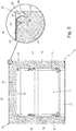
Figure 8 schematically shows a step of the assembly of the cabinet of the refrigerator shown inFigures 1 and 2 , with parts in section and parts removed for clarity's sake. - With reference to
Figures 1, 2 and3 ,reference number 1 denotes as a whole a refrigerator adapted for preserving perishable foodstuff and preferably suitable for domestic use, i.e. a household refrigerator. -
Refrigerator 1 basically comprises: a preferably substantially parallelepiped-shaped, self-supportingcabinet 2 which is structured for stably resting on the floor/ ground, has a thermal-insulating structure and is internally provided with at least one, thermal-insulated storage cavity which is adapted to accommodate perishable foodstuff and communicates with the outside via a large, preferably roughly rectangular-shaped, access opening which is located on a main face/wall of thesame cabinet 2; at least one sealing door that has a thermal-insulating structure and is flag hinged to thecabinet 2, so as to be manually rotatable to and from a closing position in which the door abuts on said main face/wall ofcabinet 2 to substantially airtight close the access opening of said storage cavity; and an electrically-operated, cooling system which is at least partially accommodated inside thecabinet 2, and is structured/adapted to cool down the inside of said inner storage cavity. - In the example shown, in particular, the access opening of said at-least-one inner storage cavity is preferably located on a substantially vertically-oriented, front face/wall of the self-supporting
cabinet 2. - In the example shown, moreover, the self-supporting
cabinet 2 is preferably provided with two, preferably substantially vertically-aligned and preferably roughly parallelepiped-shaped, adjacent and discreteinner storage cavities cabinet 2. - Preferably the
refrigerator 1 furthermore comprises, for eachinner storage cavity door cabinet 2 so as to be manually rotatable about a preferably substantially vertical-oriented, reference axis, to and from a closing position (seeFigure 2 ) in which thedoor cabinet 2, so as to cover and substantially airtight seal the access opening of thecorresponding storage cavity - The electrically-operated,
cooling system 7, in turn, is preferably structured/ adapted to separately cool down the inside of bothstorage cavities cabinet 2. - More in details, the
cooling system 7 is preferably adapted to separately cool down the inside of thestorage cavities storage cavity 3 at a first target temperature preferably suitable for short-term preservation of perishable foodstuff, and so as to keep the inside ofstorage cavity 4 at a second target temperature preferably lower than the first target temperature and/or suitable for long-term preservation of perishable foodstuff. - In the example shown, in particular, the
storage cavity 3 is located above thestorage cavity 4. Furthermore the first target temperature is preferably greater than or equal to +0°C, whereas the second target temperature is lower than +0°C. - More specifically, the first target temperature preferably ranges between +2°C and +8°C, whereas the second target temperature preferably ranges between -30°C and -10°C.
- With reference to
Figures 1 to 5 , the self-supportingcabinet 2, in turn, includes: a rigid boxlikeouter casing 10 that forms the outside ofcabinet 2; a substantially tub-shaped, rigidinner shell 11 which is stably fitted/recessed into theouter casing 10 so as to form the inside ofcabinet 2 and thus delimits the at-least-one inner storage cavity of the self-supportingcabinet 2, or rather theinner storage cavities insulating stuffing 12 which is made of a thermal-insulating material and is interposed between theouter casing 10 and theinner shell 11 to minimize the heat exchange with the outside. - Preferably the thermal-insulating
stuffing 12 is furthermore substantially rigid so as to be a bearing member of the self-supporting structure ofcabinet 2. - More in detail, the rigid
inner shell 11 is preferably made of plastic material and is preferably stably coupled/joined to theouter casing 10 on the main face/wall of the self-supportingcabinet 2, where the access opening of the/eachinner storage cavity cabinet 2 is located. - In the example shown, in particular, the rigid
inner shell 11 preferably has two substantially basin-shaped, middle portions that are arranged one spaced beside the other and each of which forms/delimits a respectiveinner storage cavity cabinet 2, and a nearly flat, peripheral portion that surrounds the middle portions and is stably joined to theouter casing 10. - Clearly the
inner shell 11 could be split up into two discrete and adjacent basin-shaped sections, each delimiting a respectiveinner storage cavity cabinet 2. - The thermal-insulating
stuffing 12, in turn, is preferably made of a hard polymeric-material foam that preferably almost completely fills up the interspace delimited by the boxlikeouter casing 10 and theinner shell 11. - With reference to
Figures 1 to 5 , the boxlikeouter casing 10, on the other hand, comprises a number of preferably substantially flat and/or substantially rectangular-shaped, rigid platelike panels that are placed side-by-side to one another, and are rigidly fixed/attached to one another and/or to the beneath-located thermal-insulatingstuffing 12, so as to form the outer walls of the self-supportingcabinet 2. - At least one of these platelike panels moreover includes, or rather basically consists of, a
metal plate 21 of appropriate thickness, which substantially resembles the shape of said platelike panel and has, along its perimeter edge, at least one outwards-extending oblong sloppedflap 22 that overlaps and is stably coupled to a sloppedsidewall 23 of a correspondingoblong receiving groove 24 formed on a rigid supportingframework 25 which is located beneath themetal plate 21 and stably supports thesame metal plate 21. - More in detail, the/each oblong slopped
flap 22 ofmetal plate 21 is preferably located on a substantially straight, section of the perimeter edge of themetal plate 21, and is adapted to overlap and stably couple to a sloppedsidewall 23 of a substantially straight,oblong receiving groove 24 formed in the beneath-located rigid supportingframework 25. - Furthermore the
metal plate 21 is preferably stably coupled to the supportingframework 25 by gluing. - More in detail the/each oblong slopped
flap 22 ofmetal plate 21 is preferably stably coupled to the corresponding sloppedsidewall 23 by gluing. - Preferably the
metal plate 21 is furthermore made of zinc-plated steel. The thickness of themetal plate 21 moreover preferably ranges between 0,5 and 3 mm (millimeters). - With reference to
Figures 3 ,4 ,5 and6 , in particular, themetal plate 21 preferably has at least a pair of outwards-extending and reciprocally diverging, oblong sloppedflaps 22 that are located on opposite sides of themetal plate 21 and each of which overlaps and stably couples to a sloppedsidewall 23 of a respective receivinggroove 24 formed a portion of said beneath-located rigid supportingframework 25. - Preferably the aforesaid at-least-one platelike panel of the
outer casing 10 additionally includes, for at least one and preferably each oblong sloppedflap 22 ofmetal plate 21, an oblong piece ofbi-adhesive tape 26 which is interposed between the sloppedflap 22 and the beneath-located sloppedsidewall 23 of the receivinggroove 24 to filmy fix themetal plate 21 to the rigid supportingframework 25. - With particular reference to
Figure 8 , additionally the tilt angle β of the sloppedsidewall 23 of the/each receivinggroove 24 with respect to the lying plane P of themetal plate 21 is lower than 90° and preferably also lower than 80°. - The bending angle α of the/each oblong slopped
flap 22 ofmetal plate 21, in turn, is lower than 90° and, when the sloppedflap 22 lies on the sloppedsidewall 23, substantially matches with the tilt angle β of the sloppedsidewall 23. - In addition to the above, when the
metal plate 21 is spaced/detached from the rigid supportingframework 25, the bending angle α of the sloppedflap 22 ofmetal plate 21 is greater than the tilt angle β of the sloppedsidewall 23 of the receivinggroove 24. Thus the sloppedflap 22 ofmetal plate 21, when abutting on the rigid supportingframework 25, is forced to plastically lean/bend backward to match the pitch of the beneath-located sloppedsidewall 23 of thegroove 24. - In other words, when abutting on the rigid supporting
framework 25, the/each sloppedflap 22 ofmetal plate 21 is plastically deformed against the sloppedsidewall 23 of receivinggroove 24. - In the example shown, in particular, the bending angle α of the/each slopped
flap 22 ofmetal plate 21 is preferably initially equal to about 70°. - More in detail, with particular reference to
Figures 4 ,5 and6 , themetal plate 21 is preferably substantially rectangular in shape and preferably has, on each of the four sides, a respective outwards-extending oblong sloppedflap 22 that overlaps and stably couples with the sloppedsidewall 23 of a corresponding receivinggroove 24 formed on a portion of the beneath-located rigid supportingframework 25. Furthermore the two oblong sloppedflaps 22 of each pair of opposite oblong sloppedflaps 22 preferably diverge to one another. - Preferably each oblong slopped
flap 22 ofmetal plate 21 is moreover stably fixed/attached to the sloppedsidewall 23 of the beneath-located receivinggroove 24 via a respective piece ofbi-adhesive tape 26 of appropriate length. - The rigid supporting
framework 25, in turn, preferably substantially copies the shape of the perimeter edge of themetal plate 21 and is preferably rigidly connected to and is stably supported by the adjacent platelike panels of theouter casing 10. - In other words, the rigid supporting
framework 25 is preferably substantially annular in shape and extends, preferably substantially without interruptions, beneath the whole perimeter edge of themetal plate 21. - Moreover the rigid supporting
framework 25 is preferably at least partially incorporated into one or more of the remaining platelike panels of theouter casing 10. - More in detail, the rigid supporting
framework 25 preferably includes one or more rigid profile members incorporated or firmly connected to one or more of the remaining adjacent platelike panels of theouter casing 10. - In addition, the receiving
groove 24 preferably has a substantially V-shaped or trapezoid-shaped cross-section. - Moreover the tilt angle β of the slopped
sidewall 23 ofgroove 24 with respect to the lying plane P of themetal plate 21 preferably ranges between 50° and 70° and is optionally equal to about 60°. - With particular reference to
Figures 3 ,4 and5 , in particular, the self-supportingcabinet 2 is substantially parallelepiped in shape and theouter casing 10, therefore, preferably comprises: a preferably substantially flat and preferably approximately rectangular-shaped, firstplatelike panel 15 forming the substantially horizontally-oriented top wall of the self-supportingcabinet 2; a pair of preferably substantially flat and preferably approximately rectangular-shaped, second rigid plate likepanels cabinet 2; a preferably substantially flat and preferably approximately rectangular-shaped, third rigidplatelike panel 18 forming the substantially vertically-oriented rear wall of the self-supportingcabinet 2; and lastly a preferably substantially flat and preferably approximately rectangular-shaped, fourth rigidplatelike panel 19 forming the substantially horizontally-oriented bottom wall of the self-supportingcabinet 2. - Preferably the
outer casing 10 additionally includes a number of preferably substantially straight,rigid stiffening crossbars 20 that rigidly connect theplatelike panels platelike panel 15 and/or theplatelike panel 19. - With reference to
Figure 6 , moreover at least one of the stiffeningcrossbars 20 is preferably divided into acentral segment 20a preferably made of metal material, and twoend segments 20b that area made of plastic material and are rigidly coupled to thecentral segment 20a on opposite sides of the latter. Preferably eachend segment 20b is moreover rigidly force-fitted/wedged to the facingplatelike panel - Moreover, with reference to
Figure 3 and4 , theplatelike panel 15 preferably basically consists of a roughly rectangular-shaped, firstrigid metal plate 21 that has, preferably roughly in the middle of each straight side, a respective outwards-extending oblong sloppedflap 22 that overlaps and is stably coupled, preferably by a piece ofbi-adhesive tape 26, to a corresponding sloppedsidewall 23 of the receivinggroove 24 formed on a complementary first rigid supportingframework 25 located beneath the sameplatelike panel 15. - The first rigid supporting
framework 25, in turn, is preferably substantially rectangular in shape so as to extend beneath the whole perimeter edge of thefirst metal plate 21, i.e. of the whole perimeter edge ofplatelike panel 15. - Moreover, the first rigid supporting
framework 25 is preferably divided into a number of discrete modular members that are rigidly coupled to one another, and one or more of these modular members are preferably incorporated either in the sides of the adjacentplatelike panels stiffening crossbars 20 rigidly connecting theplatelike panels - Preferably, the first rigid supporting
framework 25 therefore rigidly connects theplatelike panels - More specifically, the first rigid supporting
framework 25 preferably has a pair of opposite sagittal straight segments roughly parallel to the vertical midplane of the refrigerator, and a pair of opposite transversal straight segments roughly perpendicular to the vertical midplane of the refrigerator. - Each transversal straight segment of the first rigid supporting
framework 25 preferably includes arespective stiffening crossbars 20 rigidly connecting theplatelike panels platelike panel 15. - Preferably, the receiving
groove 24 that accommodates the sloppedflap 22 of thefirst metal plate 21 is furthermore located in thestiffening crossbars 20. - With reference to
Figure 7 , each sagittal straight segment of the first rigid supportingframework 25, in turn, preferably includes astraight edging member 30 preferably made of plastic, which is incorporated/located on the side of the adjacentplatelike panel - Preferably, the receiving
groove 24 that accommodates the sloppedflap 22 of thefirst metal plate 21 is furthermore located in thestraight edging member 30 of the adjacentplatelike panel - With reference to
Figures 4 and5 , in the same way theplatelike panel 18 preferably basically consists of a roughly rectangular-shaped, rigidsecond metal plate 21 that has, preferably roughly in the middle of each straight side, a respective outwards-extending oblong sloppedflap 22 that overlaps and is stably coupled, preferably by a piece ofbi-adhesive tape 26, to a corresponding sloppedsidewall 23 of the receivinggroove 24 formed on a complementary second rigid supportingframework 25 located beneath the sameplatelike panel 18. - The second rigid supporting
framework 25, in turn, is preferably substantially rectangular in shape so as to extend beneath the whole perimeter edge of thesecond metal plate 21, i.e. of the whole perimeter edge ofplatelike panel 18. - Moreover, the second rigid supporting
framework 25 is preferably divided into a number of discrete modular members that are rigidly coupled to one another, and one or more of these modular members are preferably incorporated either in the sides of the adjacentplatelike panels stiffening crossbars 20 rigidly connecting theplatelike panels - Preferably, the second rigid supporting
framework 25 therefore rigidly connects theplatelike panels - More specifically, the second rigid supporting
framework 25 preferably has a pair of opposite sagittal straight segments roughly parallel to the vertical midplane of the refrigerator, and a pair of opposite transversal straight segments roughly perpendicular to the vertical midplane of the refrigerator. - Each transversal straight segment of the second rigid supporting
framework 25 preferably includes arespective stiffening crossbars 20 rigidly connecting theplatelike panels platelike panel 18. - Preferably, the receiving
groove 24 that accommodates the sloppedflap 22 of thesecond metal plate 21 is furthermore located in thestiffening crossbars 20. - With reference to
Figure 5 , each sagittal straight segment of the second rigid supportingframework 25, in turn, includes a roughly S-folded portion of the straight side of the adjacentplatelike panel - Preferably, the receiving
groove 24 that accommodates the sloppedflap 22 of thesecond metal plate 21 is furthermore located in the roughly S-folded portion of the straight side of the adjacentplatelike panel - With reference to
Figures 3 and4 , lastly theplatelike panel 19 preferably basically consists of a roughly rectangular-shaped, rigidthird metal plate 21 which is preferably substantially Z-bent and has, preferably roughly in the middle of each straight side, a respective outwards-extending oblong sloppedflap 22 that overlaps and is stably coupled, preferably by a piece ofbi-adhesive tape 26, to a corresponding sloppedsidewall 23 of the receivinggroove 24 formed on a complementary third rigid supportingframework 25 located beneath the sameplatelike panel 19. - The third rigid supporting
framework 25, in turn, is preferably substantially rectangular in shape so as to extend beneath the whole perimeter edge of thefirst metal plate 21, i.e. of the whole perimeter edge ofplatelike panel 19. - Moreover, the third rigid supporting
framework 25 is preferably divided into a number of discrete modular members that are rigidly coupled to one another, and one or more of these modular members are preferably incorporated either in the sides of the adjacentplatelike panels stiffening crossbars 20 rigidly connecting theplatelike panels - Preferably, the third rigid supporting
framework 25 therefore rigidly connects theplatelike panels - More specifically, the third rigid supporting
framework 25 preferably has a pair of opposite sagittal segments that have a polygonal-chain profile and are roughly parallel to the vertical midplane of the refrigerator, and a pair of opposite transversal straight segments roughly perpendicular to the vertical midplane of the refrigerator. - With reference to
Figures 3 ,4 and6 , each transversal straight segment of the third rigid supportingframework 25 preferably includes acorresponding stiffening crossbars 20 rigidly connecting theplatelike panels platelike panel 19. - Preferably, the receiving
groove 24 that accommodates the sloppedflap 22 of thethird metal plate 21 is furthermore located in thestiffening crossbars 20. - Each sagittal straight segment of the third rigid supporting
framework 25, in turn, preferably includes an oblong and Z-bent,rigid member 31 which is preferably made of plastic material and is firmly fixed to a corresponding side of the adjacentplatelike panel - Preferably, the receiving
groove 24 that accommodates the sloppedflap 22 of thethird metal plate 21 is furthermore located in therigid oblong member 31 of the adjacentplatelike panel - With reference to
Figures 3 ,5 and6 , the remainingplatelike panels - With particular reference to
Figures 2 and3 , thecooling system 7, in turn, comprises an electrically-operated, heat-pump assembly which is preferably provided with two evaporators distinct/discrete to one another. The first evaporator is located inside or immediately adjacent to thestorage cavity 3, so as to cool down the air circulating inside thestorage cavity 3. The second evaporator, in turn, is located inside or immediately adjacent to thestorage cavity 4, so as to cool down the air circulating inside thestorage cavity 4. - More in detail, the heat-pump assembly preferably comprises: an electrically-operated
compressor 40 which is housed into acompressor compartment 41 located beneath theplatelike panel 19, and is adapted to compress a low-temperature and low-pressure gaseous-state refrigerant for supplying at outlet/delivery a flow of high-temperature and high-pressure refrigerant; and a first heat-exchanger 42 that receives the high-temperature and high-pressure gaseous-state refrigerant fromcompressor 40, is preferably located on the back of self-supportingcabinet 2 skimmed over theplatelike panel 18, i.e. opposite to the access openings ofstorage cavities compressor 40 to release heat to the outside air/environment, thus reducing its temperature. - Additionally the heat-pump assembly preferably comprises: a second heat-
exchanger 43 which is located immediately adjacent to thestorage cavity 3, receives the low-pressure and low-temperature refrigerant, and is structured to allow the low-pressure and low-temperature refrigerant to absorb heat from thestorage cavity 3 while flowing through the same heat-exchanger 43; and a third heat-exchanger 44 which is located immediately adjacent to thestorage cavity 4, receives the low-pressure and low-temperature refrigerant, and is structured to allow the low-pressure and low-temperature refrigerant to absorb heat from thestorage cavity 4 while flowing through the same heat-exchanger 44. - Preferably the heat-pump assembly finally comprises: a first capillary tube or other passive or active refrigerant expansion device (not shown in the figures) which is located between the heat-
exchanger 42 and the heat-exchanger 43 and is structured to cause the rapid expansion of the high-pressure refrigerant arriving from heat-exchanger 42, so as to rapidly highly reduce both temperature and pressure of the refrigerant directed towards the heat-exchanger 43; and a second capillary tube or other passive or active refrigerant expansion device (not shown in the figures) which is located between the heat-exchanger 42 and the heat-exchanger 44 and is structured to cause the rapid expansion of the high-pressure refrigerant arriving from heat-exchanger 42, so as to rapidly highly reduce both temperature and pressure of the refrigerant directed towards the heat-exchanger 44. - In addition the
cooling system 7 preferably also includes an electronic control unit (not shown in the figures) which is preferably recessed into a corresponding seat formed inside the self-supportingcabinet 2, and is adapted/configured to command the heat-pump assembly, so as to keep the temperature inside thestorage cavity 3 and the temperature inside thewhole storage cavity 4 at corresponding target temperatures. - Operation of
refrigerator 1 is identical to that of today's household refrigerators and therefore does not require further explanations. - With reference to
Figure 8 , in turn the assembly ofrefrigerator 1, or rather the assembly of the self-supportingcabinet 2 ofrefrigerator 1, comprises the steps of - cutting and bending a metal sheets of appropriate thickness, so as to form at least one,
rigid metal plates 21 which resembles the shape of a corresponding platelike panel of theouter casing 10 and additionally has, along its perimeter edge, one or more outwards-extending oblong sloppedflaps 22; - arranging the
metal plate 21 over a corresponding rigid supporting frame-work 25 that preferably substantially copies the shape of the perimeter of thesame metal plate 21; and - the step of pressing the
metal plate 21, or rather the/each outwards-extending oblong sloppedflap 22 of themetal plate 21, against the beneath-located rigid supportingframework 25 so that the/each outwards-extending oblong sloppedflap 22 overlaps and stably couples, preferably by gluing, to a corresponding sloppedsidewall 23 of a receivinggroove 24 formed on the beneath-located rigid supportingframework 25. - Additionally the aforesaid metal sheets of appropriate thickness is preferably made of zinc-plated steel.
- Preferably the assembly of
refrigerator 1, or rather the assembly of the self-supportingcabinet 2 ofrefrigerator 1, additionally comprises the step of gluing themetal plate 21 to the beneath-located rigid supportingframework 25. - More in detail, the assembly of
refrigerator 1, or rather the assembly of the self-supportingcabinet 2 ofrefrigerator 1, preferably comprises the step of gluing the the/each oblong sloppedflap 22 to the corresponding sloppedsidewall 23 of the receivinggroove 24. - Even more in detail, the assembly of
refrigerator 1, or rather the assembly of the self-supportingcabinet 2 ofrefrigerator 1, preferably additionally comprises the step of putting, before themetal plate 21 is firmly pressed against the beneath-located rigid supportingframework 25, a piece ofbi-adhesive tape 26 between the/each oblong sloppedflap 22 and the corresponding sloppedsidewall 23 of the receivinggroove 24. - Preferably, the bending angle α of the/each oblong slopped
flap 22 of themetal plate 21 with respect to the lying plane P of thesame metal plate 21 is moreover lower than 90° and optionally ranges between 60° and 80°. - More in detail, the bending angle α of each slopped
flap 22 of themetal plate 21 is preferably equal to about 70°. - Preferably the bending angle α of each outwards-extending oblong slopped
flap 22 is furthermore greater than the tilt angle β of the sloppedsidewall 23 of the receivinggroove 24 in the corresponding rigid supportingframework 25. Therefore, when overlapping the corresponding sloppedsidewall 23 of the receivinggroove 24, the/ each oblong sloppedflap 22 ofmetal plate 21 is forced to plastically deform/bend/lean backwards to match the pitch of the sloppedsidewall 23. - In the example shown in particular, the assembly method of
refrigerator 1, or rather the assembly method of the self-supportingcabinet 2 ofrefrigerator 1, comprises the step of cutting and bending a metal sheets of appropriate thickness, so as to form a number ofrigid metal plates 21, which resemble the shape of theplatelike panels outer casing 10, and each of which additionally has, along the perimeter edge, a number of outwards-extending oblong slopped flaps 22. - After having made each
rigid metal plate 21, the assembly ofrefrigerator 1 preferably additionally includes the step of attaching, beneath each oblong sloppedflap 22 of themetal plate 21, a respective oblong piece ofbi-adhesive tape 26. - The assembly of
refrigerator 1 furthermore comprises the step of arranging, on opposite sides of the rigidinner shell 11, theplatelike panels cabinet 2; and the step of placing the rigid supportingframeworks 25 between theplatelike panels - More specifically, the step of placing the rigid supporting
frameworks 25 between theplatelike panels rigid stiffening crossbars 20 between theplatelike panels - After having placed the rigid supporting
frameworks 25 between theplatelike panels refrigerator 1 comprises the step of arranging eachmetal plate 21 over the corresponding rigid supportingframework 25; and the step of pressing themetal plate 21 against the corresponding beneath-located rigid supportingframework 25 so that each outwards-extending oblong sloppedflap 22 of themetal plate 21 overlaps and stably couples, preferably by means of thebi-adhesive tape 26, to a corresponding sloppedsidewall 23 of the receivinggroove 24 formed on the beneath-located rigid supportingframework 25. - Clearly in overlapping the corresponding slopped
sidewall 23 of thegroove 24, each oblong sloppedflap 22 of themetal plate 21 plastically bends/leans backwards so as to match with the tilt angle β of the sloppedsidewall 23. - Being slopped differently to the slopped sidewalls 23 of the corresponding beneath-located rigid supporting
framework 25, the slopped flaps 22 allows the auto centering of themetal plate 21 over the rigid supportingframework 2. - When the/each
metal plate 21 is rigidly fixed, preferably by gluing, to the beneath-located rigid supportingframework 25, i.e. when the boxlikeouter casing 10 is completed, the assembly ofrefrigerator 1 preferably provides to inject a given amount of polymeric-material foam within the interspace delimited by the boxlikeouter casing 10 and theinner shell 11, so as to form the thermal-insulatingstuffing 12 and to rigidly couple theouter casing 10 and theinner shell 11 to one another. - Clearly the polymeric-material foam stably sticks on the hidden face of the/ each
metal plate 21 and, after solidification, rigidly bonds/attaches the/eachmetal plate 21 to the beneath-located rigid supportingframework 25 and to the other components forming the self-supportingcabinet 2. - The resulting particular structure of the boxlike
outer casing 10 ofcabinet 2 has several advantages. - Firstly, since all platelike panels of
outer casing 10 are made of metal, the fire resistance of self-supportingcabinet 2 is significantly increased with all advantages that this entails. The chances that sparks caused by a short-circuit in the compressor compartment can penetrating themetal plate 21 and arrive at the thermal-insulatingstuffing 12, in fact, are almost close to zero. - In addition, the presence of the oblong slopped
flaps 22 all along the perimeter edge of themetal plate 21 increases the rigidity of the panel, thus strengthening the overall structure of the self-supportingcabinet 2. - Clearly, changes may be made to the
refrigerator 1 without, however, departing from the scope of the present invention. - For example, in a less sophisticated embodiment, only the rigid
platelike panel 18 and/or the rigidplatelike panel 19 ofouter casing 10 may comprise a respective, substantially rectangular-shaped,metal plate 21 that has, along each straight side of the perimeter edge, a respective outwards-extending oblong sloppedflap 22 that overlaps and is firmly attached to a sloppedsidewall 23 of a corresponding straight receivinggroove 24 formed on a rigid supportingframework 25 which is located beneath themetal plate 21 and stably supports thesame metal plate 21. - Moreover, rather than attaching the
bi-adhesive tape 26 beneath each oblong sloppedflap 22 of themetal plate 21, the assembly ofrefrigerator 1 may comprises the step of attaching, onto the sloppedsidewall 23 of each receivinggroove 24, a respective oblong piece ofbi-adhesive tape 26. - Clearly the
bi-adhesive tape 26 may be replaced by an appropriate layer of other adhesive material. - In other words, the assembly of the self-supporting
cabinet 2 ofrefrigerator 1 may comprises the step of putting some adhesive material onto the oblong sloppedflaps 22 of themetal plate 21 and/or onto the sloppedsidewall 23 of each receivinggroove 24, so as to firmly fix/attach the slopped flaps 22, and thus thewhole metal plate 21, to the beneath-located rigid supportingframework 25.
Claims (15)
- Refrigerator (1) comprising: a self-supporting cabinet (2) which is structured for stably resting on the floor/ground, has a thermal-insulating structure and is provided with at least one, inner thermal-insulated storage cavity (3, 4) that is adapted to accommodate perishable foodstuff and communicates with the outside via an access opening located on a main face/wall of the cabinet;
the self-supporting cabinet (2), in turn, comprising: a rigid boxlike outer casing (10) that forms the outside of said self-supporting cabinet (2); a tub-shaped, rigid inner shell (11) which is stably fitted/recessed into the outer casing (10) so as to form the inside of the cabinet (2) and delimits said at-least-one inner storage cavity (3, 4); and a thermal-insulating stuffing (12) which is interposed between the inner shell (11) and the outer casing (10) to minimize the heat exchange with the outside;
the rigid boxlike outer casing (10) including a number of rigid platelike panels (15, 16, 17, 18, 19) that are placed side-by-side to one another and are firmly fixed/attached to one another and/or to the beneath-located thermal-insulating stuffing (12), so as to form the outer walls of the self-supporting cabinet (2);
the refrigerator (1) being characterized in that at least one (15, 18, 19) of said platelike panels (15, 16, 17, 18, 19) includes a metal plate (21) having, along its perimeter edge, at least one, outwards-extending slopped flap (22) that overlaps and stably couples to a slopped sidewall (23) of a corresponding receiving groove (24) formed on a corresponding rigid supporting framework (25) which is located beneath said rigid metal plate (21) and stably supports the same rigid metal plate (21). - Refrigerator according to Claim 1, wherein said oblong slopped flap (22) is plastically deformed, over the slopped sidewall (23) of the receiving groove (24), so as to match the pitch of said slopped sidewall (23).
- Refrigerator according to Claim 1 or 2, wherein the rigid supporting frame-work (25) is substantially annular in shape and substantially copies the shape of the perimeter of said metal plate (21).
- Refrigerator according to Claim 1, 2 or 3, wherein the rigid supporting frame-work (25) is at least partly integral to one or more of the remaining adjacent platelike panels (16, 17) of said rigid boxlike outer casing (10).
- Refrigerator according to Claim 4, wherein the rigid supporting frame-work (25) includes one or more rigid profile members (30, 31) firmly connected to one or more of the remaining adjacent platelike panels (16, 17) of said rigid boxlike outer casing (10).
- Refrigerator according to any one of the preceding claims, wherein said metal plate (21) has at least a pair of outwards-extending and reciprocally diverging, slopped flaps (22) that are located on opposite sides of the same metal plate (21), and each of which overlaps and stably couples to a slopped sidewall (23) of a respective receiving groove (24) formed on said beneath-located rigid supporting framework (25).
- Refrigerator according to any one of the preceding claims, wherein said at least one, slopped flap (22) is rigidly fixed to the beneath-located slopped sidewall (23) by gluing.
- Refrigerator according to any one of the preceding claims, wherein the self-supporting cabinet (2) is substantially parallelepiped in shape and the outer casing (10) comprises: a first platelike panel (15) forming the substantially horizontally-oriented top wall of the self-supporting cabinet (2); a pair of second rigid plate like panels (16, 17) forming the substantially vertically-oriented and reciprocally-faced, opposite side walls of the self-supporting cabinet (2); a third rigid platelike panel (18) forming the substantially vertically-oriented rear wall of the self-supporting cabinet (2); and a fourth rigid platelike panel (19) forming the substantially horizontally-oriented bottom wall of the self-supporting cabinet (2); said first platelike panel (15) and/or said second platelike panel (18) and/or said third platelike panel (18) including said metal plate (21) with at least one outwards-extending slopped flap (22).
- Refrigerator according to Claim 8, wherein the outer casing (10) additionally includes a number of stiffening crossbars (20) that rigidly connect said second platelike panels (16, 17) to one another.
- Refrigerator according to Claim 9, wherein said rigid supporting framework (25) is partially incorporated into one of said stiffening crossbars (20).
- Refrigerator according to any one of the preceding claims, wherein said receiving groove (24) has a substantially V-shaped or trapezoid-shaped cross-section.
- Assembly method of a refrigerator (1) having a self-supporting cabinet (2) which is structured for stably resting on the floor/ground, has a thermal-insulating structure and is provided with at least one, inner thermal-insulated storage cavity (3, 4) that is adapted to accommodate perishable foodstuff and communicates with the outside via an access opening located on a main face/wall of the cabinet;
the self-supporting cabinet (2) comprising: a rigid boxlike outer casing (10) that forms the outside of said self-supporting cabinet (2); a tub-shaped, rigid inner shell (11) which is stably fitted/recessed into the outer casing (10) so as to form the inside of the cabinet (2) and delimits said at-least-one inner storage cavity (3, 4); and a thermal-insulating stuffing (12) which is interposed between the inner shell (11) and the outer casing (10) to minimize the heat exchange with the outside;
the rigid boxlike outer casing (10) including a number of rigid platelike panels (15, 16, 17, 18, 19) that are placed side-by-side to one another and are firmly fixed/attached to one another and/or to the beneath-located thermal-insulating stuffing (12), so as to form the outer walls of the self-supporting cabinet (2);
the assembly method being characterized in that it comprises the step of cutting and bending a metal sheets of appropriate thickness, so as to form at least one metal plate (21) having, along the perimeter edge, one or more outwards-extending slopped flaps (22); the step of arranging said metal plate (21) over a corresponding rigid supporting framework (25); and the step of pressing the metal plate (21) against the beneath-located rigid supporting framework (25) so that said outwards-extending slopped flap/s (22) of the metal plate (21) overlap/s and stably couple/s to a corresponding slopped sidewall (23) of a receiving groove (24) formed on the beneath-located rigid supporting framework (25). - Assembly method according to Claim 12, characterized in that the bending angle (α) of the/each slopped flap (22) of said metal plate (21) with respect to the lying plane (P) of the metal plate (21) is greater than the tilt angle (β) of the corresponding slopped sidewall (23) of the receiving groove (24) with respect to the same lying plane (P) of the metal plate (21), so that the/each slopped flap (22) is forced to plastically bend/lean backwards when overlapping the corresponding slopped sidewall (23) of the receiving groove (24).
- Assembly method according to Claim 12 or 13, characterized by additionally comprising, before the step of pressing the metal plate (21) against the beneath-located rigid supporting framework (25), the step of putting an adhesive material (26) between said slopped flap/s (22) of the metal plate (21) and the corresponding slopped sidewall (23) of the receiving groove (24).
- Assembly method according to Claim 12, 13 or 14, wherein the bending angle (α) of the/each outwards-extending slopped flap (22) of the metal plate (21) with respect to the lying plane (P) of the same metal plate (21) ranges between 60° and 80°.
Priority Applications (2)
| Application Number | Priority Date | Filing Date | Title |
|---|---|---|---|
| EP19202945.2A EP3809077B1 (en) | 2019-10-14 | 2019-10-14 | Refrigerator and assembly method thereof |
| PCT/EP2020/077335 WO2021073872A1 (en) | 2019-10-14 | 2020-09-30 | Refrigerator and assembly method thereof |
Applications Claiming Priority (1)
| Application Number | Priority Date | Filing Date | Title |
|---|---|---|---|
| EP19202945.2A EP3809077B1 (en) | 2019-10-14 | 2019-10-14 | Refrigerator and assembly method thereof |
Publications (2)
| Publication Number | Publication Date |
|---|---|
| EP3809077A1 true EP3809077A1 (en) | 2021-04-21 |
| EP3809077B1 EP3809077B1 (en) | 2024-12-11 |
Family
ID=68280954
Family Applications (1)
| Application Number | Title | Priority Date | Filing Date |
|---|---|---|---|
| EP19202945.2A Active EP3809077B1 (en) | 2019-10-14 | 2019-10-14 | Refrigerator and assembly method thereof |
Country Status (2)
| Country | Link |
|---|---|
| EP (1) | EP3809077B1 (en) |
| WO (1) | WO2021073872A1 (en) |
Families Citing this family (1)
| Publication number | Priority date | Publication date | Assignee | Title |
|---|---|---|---|---|
| WO2025247029A1 (en) * | 2024-05-27 | 2025-12-04 | 青岛海尔电冰箱有限公司 | Box body and storage device |
Citations (3)
| Publication number | Priority date | Publication date | Assignee | Title |
|---|---|---|---|---|
| US3221085A (en) * | 1961-08-28 | 1965-11-30 | Gen Motors Corp | Process of making an insulated cabinet |
| US5908229A (en) * | 1997-10-23 | 1999-06-01 | Whirlpool Corporation | Outer shell of refrigerator cabinet |
| DE102007011113A1 (en) * | 2007-03-07 | 2008-09-11 | BSH Bosch und Siemens Hausgeräte GmbH | Refrigerator housing for refrigeration equipment has an external skin, an internal container and a layer of insulating material enclosed between the external skin and the internal container |
-
2019
- 2019-10-14 EP EP19202945.2A patent/EP3809077B1/en active Active
-
2020
- 2020-09-30 WO PCT/EP2020/077335 patent/WO2021073872A1/en not_active Ceased
Patent Citations (3)
| Publication number | Priority date | Publication date | Assignee | Title |
|---|---|---|---|---|
| US3221085A (en) * | 1961-08-28 | 1965-11-30 | Gen Motors Corp | Process of making an insulated cabinet |
| US5908229A (en) * | 1997-10-23 | 1999-06-01 | Whirlpool Corporation | Outer shell of refrigerator cabinet |
| DE102007011113A1 (en) * | 2007-03-07 | 2008-09-11 | BSH Bosch und Siemens Hausgeräte GmbH | Refrigerator housing for refrigeration equipment has an external skin, an internal container and a layer of insulating material enclosed between the external skin and the internal container |
Also Published As
| Publication number | Publication date |
|---|---|
| EP3809077B1 (en) | 2024-12-11 |
| WO2021073872A1 (en) | 2021-04-22 |
Similar Documents
| Publication | Publication Date | Title |
|---|---|---|
| RU2629967C2 (en) | Thermal insulating box-shaped body and refrigerator | |
| RU2632982C2 (en) | Thermally insulating box frame, refrigerator and device comprising thermally insulating box frame | |
| EP3647695B1 (en) | Refrigerator | |
| RU2010152655A (en) | REFRIGERATOR | |
| EP1691152A1 (en) | Modular refrigeration unit and process for assembling a modular refrigeration unit to a cabinet of a refrigeration appliance | |
| EP4004465B1 (en) | Vacuum adiabatic module, refrigerator, and method for fabricating the refrigerator | |
| EP3775728B1 (en) | Refrigerator | |
| EP2787312A1 (en) | Refrigerator | |
| EP3809077B1 (en) | Refrigerator and assembly method thereof | |
| CN113544450B (en) | Refrigerator and manufacturing method thereof | |
| KR100950846B1 (en) | freezer | |
| CN110285095B (en) | Volute, refrigeration system and refrigeration equipment having the same | |
| KR100724445B1 (en) | Home prefab refrigerator | |
| US20210116161A1 (en) | Refrigerator | |
| CN115993035A (en) | Refrigeration equipment box and refrigeration equipment | |
| EP3885679A1 (en) | Refrigerator | |
| CN117249636A (en) | Air duct system and refrigeration equipment for refrigeration equipment | |
| CN223869594U (en) | refrigerator | |
| CN223869592U (en) | Refrigerator and door body thereof | |
| JP2020169815A (en) | refrigerator | |
| JP2002048456A (en) | Cooling storage compartment | |
| WO2022073594A1 (en) | Refrigerator | |
| WO2010133559A2 (en) | Refrigerator | |
| EP4597011A1 (en) | Refrigerator | |
| JP2005156080A (en) | refrigerator |
Legal Events
| Date | Code | Title | Description |
|---|---|---|---|
| PUAI | Public reference made under article 153(3) epc to a published international application that has entered the european phase |
Free format text: ORIGINAL CODE: 0009012 |
|
| STAA | Information on the status of an ep patent application or granted ep patent |
Free format text: STATUS: THE APPLICATION HAS BEEN PUBLISHED |
|
| AK | Designated contracting states |
Kind code of ref document: A1 Designated state(s): AL AT BE BG CH CY CZ DE DK EE ES FI FR GB GR HR HU IE IS IT LI LT LU LV MC MK MT NL NO PL PT RO RS SE SI SK SM TR |
|
| AX | Request for extension of the european patent |
Extension state: BA ME |
|
| STAA | Information on the status of an ep patent application or granted ep patent |
Free format text: STATUS: REQUEST FOR EXAMINATION WAS MADE |
|
| 17P | Request for examination filed |
Effective date: 20211021 |
|
| RBV | Designated contracting states (corrected) |
Designated state(s): AL AT BE BG CH CY CZ DE DK EE ES FI FR GB GR HR HU IE IS IT LI LT LU LV MC MK MT NL NO PL PT RO RS SE SI SK SM TR |
|
| STAA | Information on the status of an ep patent application or granted ep patent |
Free format text: STATUS: EXAMINATION IS IN PROGRESS |
|
| 17Q | First examination report despatched |
Effective date: 20230728 |
|
| GRAP | Despatch of communication of intention to grant a patent |
Free format text: ORIGINAL CODE: EPIDOSNIGR1 |
|
| STAA | Information on the status of an ep patent application or granted ep patent |
Free format text: STATUS: GRANT OF PATENT IS INTENDED |
|
| INTG | Intention to grant announced |
Effective date: 20240621 |
|
| P01 | Opt-out of the competence of the unified patent court (upc) registered |
Free format text: CASE NUMBER: APP_48408/2024 Effective date: 20240823 |
|
| GRAS | Grant fee paid |
Free format text: ORIGINAL CODE: EPIDOSNIGR3 |
|
| GRAA | (expected) grant |
Free format text: ORIGINAL CODE: 0009210 |
|
| STAA | Information on the status of an ep patent application or granted ep patent |
Free format text: STATUS: THE PATENT HAS BEEN GRANTED |
|
| AK | Designated contracting states |
Kind code of ref document: B1 Designated state(s): AL AT BE BG CH CY CZ DE DK EE ES FI FR GB GR HR HU IE IS IT LI LT LU LV MC MK MT NL NO PL PT RO RS SE SI SK SM TR |
|
| REG | Reference to a national code |
Ref country code: GB Ref legal event code: FG4D |
|
| REG | Reference to a national code |
Ref country code: CH Ref legal event code: EP |
|
| REG | Reference to a national code |
Ref country code: IE Ref legal event code: FG4D |
|
| REG | Reference to a national code |
Ref country code: DE Ref legal event code: R096 Ref document number: 602019063307 Country of ref document: DE |
|
| REG | Reference to a national code |
Ref country code: LT Ref legal event code: MG9D |
|
| PG25 | Lapsed in a contracting state [announced via postgrant information from national office to epo] |
Ref country code: HR Free format text: LAPSE BECAUSE OF FAILURE TO SUBMIT A TRANSLATION OF THE DESCRIPTION OR TO PAY THE FEE WITHIN THE PRESCRIBED TIME-LIMIT Effective date: 20241211 |
|
| PG25 | Lapsed in a contracting state [announced via postgrant information from national office to epo] |
Ref country code: FI Free format text: LAPSE BECAUSE OF FAILURE TO SUBMIT A TRANSLATION OF THE DESCRIPTION OR TO PAY THE FEE WITHIN THE PRESCRIBED TIME-LIMIT Effective date: 20241211 |
|
| PG25 | Lapsed in a contracting state [announced via postgrant information from national office to epo] |
Ref country code: BG Free format text: LAPSE BECAUSE OF FAILURE TO SUBMIT A TRANSLATION OF THE DESCRIPTION OR TO PAY THE FEE WITHIN THE PRESCRIBED TIME-LIMIT Effective date: 20241211 |
|
| REG | Reference to a national code |
Ref country code: NL Ref legal event code: MP Effective date: 20241211 |
|
| PG25 | Lapsed in a contracting state [announced via postgrant information from national office to epo] |
Ref country code: ES Free format text: LAPSE BECAUSE OF FAILURE TO SUBMIT A TRANSLATION OF THE DESCRIPTION OR TO PAY THE FEE WITHIN THE PRESCRIBED TIME-LIMIT Effective date: 20241211 |
|
| PG25 | Lapsed in a contracting state [announced via postgrant information from national office to epo] |
Ref country code: NO Free format text: LAPSE BECAUSE OF FAILURE TO SUBMIT A TRANSLATION OF THE DESCRIPTION OR TO PAY THE FEE WITHIN THE PRESCRIBED TIME-LIMIT Effective date: 20250311 |
|
| PG25 | Lapsed in a contracting state [announced via postgrant information from national office to epo] |
Ref country code: GR Free format text: LAPSE BECAUSE OF FAILURE TO SUBMIT A TRANSLATION OF THE DESCRIPTION OR TO PAY THE FEE WITHIN THE PRESCRIBED TIME-LIMIT Effective date: 20250312 Ref country code: LV Free format text: LAPSE BECAUSE OF FAILURE TO SUBMIT A TRANSLATION OF THE DESCRIPTION OR TO PAY THE FEE WITHIN THE PRESCRIBED TIME-LIMIT Effective date: 20241211 |
|
| PG25 | Lapsed in a contracting state [announced via postgrant information from national office to epo] |
Ref country code: RS Free format text: LAPSE BECAUSE OF FAILURE TO SUBMIT A TRANSLATION OF THE DESCRIPTION OR TO PAY THE FEE WITHIN THE PRESCRIBED TIME-LIMIT Effective date: 20250311 |
|
| PG25 | Lapsed in a contracting state [announced via postgrant information from national office to epo] |
Ref country code: NL Free format text: LAPSE BECAUSE OF FAILURE TO SUBMIT A TRANSLATION OF THE DESCRIPTION OR TO PAY THE FEE WITHIN THE PRESCRIBED TIME-LIMIT Effective date: 20241211 |
|
| REG | Reference to a national code |
Ref country code: AT Ref legal event code: MK05 Ref document number: 1750669 Country of ref document: AT Kind code of ref document: T Effective date: 20241211 |
|
| PG25 | Lapsed in a contracting state [announced via postgrant information from national office to epo] |
Ref country code: SM Free format text: LAPSE BECAUSE OF FAILURE TO SUBMIT A TRANSLATION OF THE DESCRIPTION OR TO PAY THE FEE WITHIN THE PRESCRIBED TIME-LIMIT Effective date: 20241211 |
|
| PG25 | Lapsed in a contracting state [announced via postgrant information from national office to epo] |
Ref country code: PL Free format text: LAPSE BECAUSE OF FAILURE TO SUBMIT A TRANSLATION OF THE DESCRIPTION OR TO PAY THE FEE WITHIN THE PRESCRIBED TIME-LIMIT Effective date: 20241211 |
|
| PG25 | Lapsed in a contracting state [announced via postgrant information from national office to epo] |
Ref country code: IS Free format text: LAPSE BECAUSE OF FAILURE TO SUBMIT A TRANSLATION OF THE DESCRIPTION OR TO PAY THE FEE WITHIN THE PRESCRIBED TIME-LIMIT Effective date: 20250411 |
|
| PG25 | Lapsed in a contracting state [announced via postgrant information from national office to epo] |
Ref country code: PT Free format text: LAPSE BECAUSE OF FAILURE TO SUBMIT A TRANSLATION OF THE DESCRIPTION OR TO PAY THE FEE WITHIN THE PRESCRIBED TIME-LIMIT Effective date: 20250411 |
|
| PG25 | Lapsed in a contracting state [announced via postgrant information from national office to epo] |
Ref country code: EE Free format text: LAPSE BECAUSE OF FAILURE TO SUBMIT A TRANSLATION OF THE DESCRIPTION OR TO PAY THE FEE WITHIN THE PRESCRIBED TIME-LIMIT Effective date: 20241211 |
|
| PG25 | Lapsed in a contracting state [announced via postgrant information from national office to epo] |
Ref country code: RO Free format text: LAPSE BECAUSE OF FAILURE TO SUBMIT A TRANSLATION OF THE DESCRIPTION OR TO PAY THE FEE WITHIN THE PRESCRIBED TIME-LIMIT Effective date: 20241211 Ref country code: AT Free format text: LAPSE BECAUSE OF FAILURE TO SUBMIT A TRANSLATION OF THE DESCRIPTION OR TO PAY THE FEE WITHIN THE PRESCRIBED TIME-LIMIT Effective date: 20241211 |
|
| PG25 | Lapsed in a contracting state [announced via postgrant information from national office to epo] |
Ref country code: SK Free format text: LAPSE BECAUSE OF FAILURE TO SUBMIT A TRANSLATION OF THE DESCRIPTION OR TO PAY THE FEE WITHIN THE PRESCRIBED TIME-LIMIT Effective date: 20241211 |
|
| PG25 | Lapsed in a contracting state [announced via postgrant information from national office to epo] |
Ref country code: CZ Free format text: LAPSE BECAUSE OF FAILURE TO SUBMIT A TRANSLATION OF THE DESCRIPTION OR TO PAY THE FEE WITHIN THE PRESCRIBED TIME-LIMIT Effective date: 20241211 |
|
| PG25 | Lapsed in a contracting state [announced via postgrant information from national office to epo] |
Ref country code: SE Free format text: LAPSE BECAUSE OF FAILURE TO SUBMIT A TRANSLATION OF THE DESCRIPTION OR TO PAY THE FEE WITHIN THE PRESCRIBED TIME-LIMIT Effective date: 20241211 |
|
| REG | Reference to a national code |
Ref country code: DE Ref legal event code: R097 Ref document number: 602019063307 Country of ref document: DE |
|
| PG25 | Lapsed in a contracting state [announced via postgrant information from national office to epo] |
Ref country code: DK Free format text: LAPSE BECAUSE OF FAILURE TO SUBMIT A TRANSLATION OF THE DESCRIPTION OR TO PAY THE FEE WITHIN THE PRESCRIBED TIME-LIMIT Effective date: 20241211 |
|
| PGFP | Annual fee paid to national office [announced via postgrant information from national office to epo] |
Ref country code: TR Payment date: 20250930 Year of fee payment: 7 |
|
| PLBE | No opposition filed within time limit |
Free format text: ORIGINAL CODE: 0009261 |
|
| STAA | Information on the status of an ep patent application or granted ep patent |
Free format text: STATUS: NO OPPOSITION FILED WITHIN TIME LIMIT |
|
| 26N | No opposition filed |
Effective date: 20250912 |
|
| PGFP | Annual fee paid to national office [announced via postgrant information from national office to epo] |
Ref country code: DE Payment date: 20251028 Year of fee payment: 7 |
|
| PGFP | Annual fee paid to national office [announced via postgrant information from national office to epo] |
Ref country code: IT Payment date: 20251022 Year of fee payment: 7 |