EP3809043A1 - Soundproof fume discharge conduit - Google Patents
Soundproof fume discharge conduit Download PDFInfo
- Publication number
- EP3809043A1 EP3809043A1 EP20201665.5A EP20201665A EP3809043A1 EP 3809043 A1 EP3809043 A1 EP 3809043A1 EP 20201665 A EP20201665 A EP 20201665A EP 3809043 A1 EP3809043 A1 EP 3809043A1
- Authority
- EP
- European Patent Office
- Prior art keywords
- conduit
- stretch
- walls
- sound absorbing
- absorbing material
- Prior art date
- Legal status (The legal status is an assumption and is not a legal conclusion. Google has not performed a legal analysis and makes no representation as to the accuracy of the status listed.)
- Granted
Links
Images



Classifications
-
- F—MECHANICAL ENGINEERING; LIGHTING; HEATING; WEAPONS; BLASTING
- F23—COMBUSTION APPARATUS; COMBUSTION PROCESSES
- F23J—REMOVAL OR TREATMENT OF COMBUSTION PRODUCTS OR COMBUSTION RESIDUES; FLUES
- F23J13/00—Fittings for chimneys or flues
- F23J13/04—Joints; Connections
-
- E—FIXED CONSTRUCTIONS
- E04—BUILDING
- E04B—GENERAL BUILDING CONSTRUCTIONS; WALLS, e.g. PARTITIONS; ROOFS; FLOORS; CEILINGS; INSULATION OR OTHER PROTECTION OF BUILDINGS
- E04B1/00—Constructions in general; Structures which are not restricted either to walls, e.g. partitions, or floors or ceilings or roofs
- E04B1/62—Insulation or other protection; Elements or use of specified material therefor
- E04B1/74—Heat, sound or noise insulation, absorption, or reflection; Other building methods affording favourable thermal or acoustical conditions, e.g. accumulating of heat within walls
- E04B1/82—Heat, sound or noise insulation, absorption, or reflection; Other building methods affording favourable thermal or acoustical conditions, e.g. accumulating of heat within walls specifically with respect to sound only
- E04B1/84—Sound-absorbing elements
-
- F—MECHANICAL ENGINEERING; LIGHTING; HEATING; WEAPONS; BLASTING
- F23—COMBUSTION APPARATUS; COMBUSTION PROCESSES
- F23J—REMOVAL OR TREATMENT OF COMBUSTION PRODUCTS OR COMBUSTION RESIDUES; FLUES
- F23J13/00—Fittings for chimneys or flues
- F23J13/02—Linings; Jackets; Casings
-
- F—MECHANICAL ENGINEERING; LIGHTING; HEATING; WEAPONS; BLASTING
- F24—HEATING; RANGES; VENTILATING
- F24F—AIR-CONDITIONING; AIR-HUMIDIFICATION; VENTILATION; USE OF AIR CURRENTS FOR SCREENING
- F24F13/00—Details common to, or for air-conditioning, air-humidification, ventilation or use of air currents for screening
- F24F13/24—Means for preventing or suppressing noise
-
- F—MECHANICAL ENGINEERING; LIGHTING; HEATING; WEAPONS; BLASTING
- F27—FURNACES; KILNS; OVENS; RETORTS
- F27B—FURNACES, KILNS, OVENS OR RETORTS IN GENERAL; OPEN SINTERING OR LIKE APPARATUS
- F27B1/00—Shaft or like vertical or substantially vertical furnaces
- F27B1/10—Details, accessories or equipment specially adapted for furnaces of these types
- F27B1/18—Arrangements of dust collectors
-
- F—MECHANICAL ENGINEERING; LIGHTING; HEATING; WEAPONS; BLASTING
- F27—FURNACES; KILNS; OVENS; RETORTS
- F27B—FURNACES, KILNS, OVENS OR RETORTS IN GENERAL; OPEN SINTERING OR LIKE APPARATUS
- F27B3/00—Hearth-type furnaces, e.g. of reverberatory type; Electric arc furnaces ; Tank furnaces
- F27B3/10—Details, accessories or equipment, e.g. dust-collectors, specially adapted for hearth-type furnaces
-
- F—MECHANICAL ENGINEERING; LIGHTING; HEATING; WEAPONS; BLASTING
- F27—FURNACES; KILNS; OVENS; RETORTS
- F27D—DETAILS OR ACCESSORIES OF FURNACES, KILNS, OVENS OR RETORTS, IN SO FAR AS THEY ARE OF KINDS OCCURRING IN MORE THAN ONE KIND OF FURNACE
- F27D17/00—Arrangements for using waste heat; Arrangements for using, or disposing of, waste gases
- F27D17/30—Arrangements for extraction or collection of waste gases; Hoods therefor
- F27D17/302—Constructional details of ancillary components, e.g. waste gas conduits or seals
-
- E—FIXED CONSTRUCTIONS
- E04—BUILDING
- E04B—GENERAL BUILDING CONSTRUCTIONS; WALLS, e.g. PARTITIONS; ROOFS; FLOORS; CEILINGS; INSULATION OR OTHER PROTECTION OF BUILDINGS
- E04B1/00—Constructions in general; Structures which are not restricted either to walls, e.g. partitions, or floors or ceilings or roofs
- E04B1/62—Insulation or other protection; Elements or use of specified material therefor
- E04B1/74—Heat, sound or noise insulation, absorption, or reflection; Other building methods affording favourable thermal or acoustical conditions, e.g. accumulating of heat within walls
- E04B1/82—Heat, sound or noise insulation, absorption, or reflection; Other building methods affording favourable thermal or acoustical conditions, e.g. accumulating of heat within walls specifically with respect to sound only
- E04B1/84—Sound-absorbing elements
- E04B2001/8457—Solid slabs or blocks
- E04B2001/8476—Solid slabs or blocks with acoustical cavities, with or without acoustical filling
- E04B2001/848—Solid slabs or blocks with acoustical cavities, with or without acoustical filling the cavities opening onto the face of the element
- E04B2001/8485—Solid slabs or blocks with acoustical cavities, with or without acoustical filling the cavities opening onto the face of the element the opening being restricted, e.g. forming Helmoltz resonators
-
- F—MECHANICAL ENGINEERING; LIGHTING; HEATING; WEAPONS; BLASTING
- F23—COMBUSTION APPARATUS; COMBUSTION PROCESSES
- F23J—REMOVAL OR TREATMENT OF COMBUSTION PRODUCTS OR COMBUSTION RESIDUES; FLUES
- F23J2213/00—Chimneys or flues
- F23J2213/10—Linings
-
- F—MECHANICAL ENGINEERING; LIGHTING; HEATING; WEAPONS; BLASTING
- F23—COMBUSTION APPARATUS; COMBUSTION PROCESSES
- F23J—REMOVAL OR TREATMENT OF COMBUSTION PRODUCTS OR COMBUSTION RESIDUES; FLUES
- F23J2213/00—Chimneys or flues
- F23J2213/70—Safety arrangements
-
- F—MECHANICAL ENGINEERING; LIGHTING; HEATING; WEAPONS; BLASTING
- F23—COMBUSTION APPARATUS; COMBUSTION PROCESSES
- F23J—REMOVAL OR TREATMENT OF COMBUSTION PRODUCTS OR COMBUSTION RESIDUES; FLUES
- F23J2900/00—Special arrangements for conducting or purifying combustion fumes; Treatment of fumes or ashes
- F23J2900/13003—Means for reducing the noise in smoke conducing ducts or systems
-
- F—MECHANICAL ENGINEERING; LIGHTING; HEATING; WEAPONS; BLASTING
- F24—HEATING; RANGES; VENTILATING
- F24F—AIR-CONDITIONING; AIR-HUMIDIFICATION; VENTILATION; USE OF AIR CURRENTS FOR SCREENING
- F24F13/00—Details common to, or for air-conditioning, air-humidification, ventilation or use of air currents for screening
- F24F13/24—Means for preventing or suppressing noise
- F24F2013/242—Sound-absorbing material
Definitions
- the present invention relates to a soundproof fume discharge conduit, which is particularly suitable to be connected to an outlet chimney of a fume suction line, adapted to be positioned, for example, in a steel plant. More specifically, such a conduit is designed to soundproof the delivery of the fans connected to the outlet chimneys for discharging fumes into the environment, said outlet chimneys being associated with melting systems.
- Fume discharge conduits are known in the art, through which the fumes generated by the steel plants comprising melting systems, such as for example electric furnaces, are discharged into the environment upon passage through suitable filtration systems.
- the fumes are directed to the discharge conduits by means of specific ventilation and conveying systems which cooperate with the chimney.
- said sound absorbing panels are subject to early wear due to the sound waves and the aerodynamic fluctuations. Moreover, over time they have the drawback of releasing fibers, dust or particles having various granulometry into the environment. Therefore, a further and often significant secondary pollution is generated. In particular, health problems may arise when the mineral wool (e.g. glass wool) is employed as a sound absorbing material. Indeed, the potentially carcinogenic micro mineral wool fibers may be inhaled.
- the mineral wool e.g. glass wool
- Such air dispersion into the environment also causes a progressive thinning of the sound absorbing layer and therefore a substantial reduction of the sound absorbing power of the panel.
- a known solution to dampen the sound waves provides orienting the conduits according to a single elbow curve having a right angle. This geometry is associated with side walls made of sound absorbing material not subject to air dispersion or even parallel partitions of said material arranged in the inner volume of the conduit.
- this solution has considerable problems of loss of load in transporting the gas through the chimney, this due to the broad angle used to bend the conduit.
- a soundproof fume discharge conduit adapted to be arranged between a ventilation system and an outlet chimney, the conduit defining a fume path therein; wherein at least one side surface of the conduit is provided with at least two protrusions, each protrusion internally defining a respective step-shaped recess, whereby the path is provided with at least two step-shaped recesses adapted to reflect sound waves propagating along the path; wherein the step shape of each recess is defined by two first walls, which are incident at a first end thereof, and at least one wall of the two first walls is coated with a first sound absorbing material.
- the invention also relates to a fume outlet chimney of a steel plant according to claim 13, said chimney being connected, in particular at the bottom, to at least one fume discharge conduit.
- the conduit of the invention advantageously allows an increased reduction of the sound emissions to be obtained without negatively altering the flow rate of the gases or fumes and without simultaneously increasing installation costs.
- the conduit of the invention also allows the low frequencies to be adequately soundproofed, which are those which are conventionally propagated at long distances, having practically zero dissipations in the free air. Therefore, it is not required to raise the characteristic frequencies of fans, whereby the costs and dimensions are curbed.
- the sound waves generated by the fans of the fume suction line are absorbed and/or reflected by the inner steps in an optimal manner.
- the upward waves advantageously have a gradually decreasing intensity with respect to the initial waves generated by the fans, according to the height thereof.
- a sound absorbing perforated sheet panel can suitably be installed to increase the noise reduction effect.
- the panel is positioned so as to delimit areas or cavities together with the inner walls forming each step.
- steps are substantially arranged in series, for example the steps are arranged in series along an axis.
- one or more other surfaces or portions of surfaces of the conduit are provided with a series of steps, each series preferably comprising at least two steps.
- the steps preferably have relatively small sizes so as not to have substantial decreases in the flow rate of fluid to the chimney, therefore avoiding undesired losses of load.
- At least one of the steps preferably has a width and height less than the width of the conduit, preferably less than half the average diameter of the conduit, or less than half the width thereof in the event of polygonal conduits.
- the width of the step and the width of the conduit are preferably measured along a same axis.
- the width of the step and the height of the step are transversal to each other, for example orthogonal to each other.
- the steps preferably extend, in particular, radially outward with respect to the chimney.
- the fume discharge conduit 1 is soundproof and is adapted to be arranged between a ventilation system (not shown) and a chimney 20 (partially shown in Figure 3 ).
- the conduit 1 is particularly adapted to be connected to the ventilation system and to the chimney 20.
- One or more conduits 1, for example one, two, three or four conduits 1, can be connected to the chimney 20.
- the conduit 1 comprises an inlet section 61, through which the fumes are emitted into conduit 1, and an outlet section 71, from which the fumes leave the conduit 1 to be introduced into the chimney 20.
- the conduit 1 is a suction branch of the chimney 20.
- the conduit 1 defines a fume path therein, and at least one side surface of conduit 1 is provided with at least two protrusions 2.
- Each protrusion 2 internally defines a respective step-shaped recess 3, whereby the path is provided with at least two step-shaped recesses 3.
- the step-shaped recesses 3 are advantageously adapted to reflect sound waves, in particular generated by the ventilation system, which propagate along the fume path defined by the conduit 1.
- Figure 10 diagrammatically shows the upward sound waves and the sound waves which are advantageously absorbed and/or reflected by the steps 3, in particular by the walls 4 and/or by the walls 5.
- each recess 3 indeed is defined by two walls 4, 5 (also called first walls) which are incident at a first end thereof 41, 51 ( Figure 1 ).
- each recess 3, also called step 3 at least one wall of the two walls 4, 5 is coated with a sound absorbing material.
- the wall 4 and/or the wall 5 are coated with sound absorbing material.
- the surface, inside the conduit 1, of the wall 4 and/or of the wall 5 is coated with sound absorbing material.
- the sound absorbing material preferably comprises or consists of expanded clay, in particular expanded clay granules, or steel wool or mineral wool or polyester fluff.
- the end 41 of the wall 4 is preferably joined, in particular directly joined, to the end 51 of wall 5.
- the recesses 3 preferably are consecutive to one another, preferably adjacent to one another.
- At least one wall 5 of one protrusion 2 is preferably joined to a respective wall 4 of the consecutive protrusion 2.
- the wall 4 and the wall 5 are mutually inclined.
- the wall 4, with wall 5, forms an angle, for example but not exclusively equal to about 90°.
- the walls 4 are parallel to one another and/or the walls 5 are parallel to one another.
- said at least two protrusions 2 are externally step-shaped.
- the conduit 1 comprises two mutually inclined stretches 6, 7.
- the two stretches 6, 7 are joined to each other by a connecting stretch 72 which is preferably curved.
- the connecting stretch 72 preferably is a portion of the stretch 7.
- the stretch 6 of the conduit 1 is adapted to be connected to the ventilation system.
- the inlet section 61 of the conduit 1 is preferably delimited by the stretch 6.
- the stretch 6 defines a longitudinal axis X.
- the longitudinal axis X preferably crosses the inlet section 61.
- the stretch 7 of the conduit 1 is adapted to be connected to the outlet chimney 20.
- the outlet section 71 of the conduit 1 is preferably delimited by the stretch 7.
- the stretch 7 defines a longitudinal axis Y, which is inclined with respect to the longitudinal axis X of the stretch 6.
- the longitudinal axis Y preferably crosses the outlet section 71.
- At least the upper surface 79 of the stretch 7 is provided with at least two protrusions 2, for example three protrusions 2, as shown in Figure 1 , or four protrusions 2, as shown in Figures 3, 4 , 5, 6 , 8 , 9, 10 , in which the fourth protrusion preferably is at the upper surface of the connecting stretch 72.
- the upper surface 79 of the stretch 7 is, in particular, the surface which is distal from the chimney 20 when the conduit 1 is connected to the chimney 20.
- at least part of the upper surface 79 is substantially opposed to the outlet section 71.
- the protrusions 2 are preferably arranged in sequence, for example in sequence substantially along the axis Y.
- the stretch 7 preferably has a circular or polygonal cross-section.
- the cross-section of the stretch 7 can, for example, be substantially quadrangular, in particular in the variants shown in Figures 8 and 9 .
- Figure 8 shows a variant in which also the lower surface 78 of the stretch 7 is provided with protrusions 2, for example two protrusions 2.
- the lower surface 78 preferably is close to, for example adjacent to, the outlet section of the conduit 1.
- each protrusion 2 internally defines a respective step-shaped recess 3, substantially as described above.
- the protrusions 2 protrude outward so as not to substantially alter the flow rate of the fumes.
- the side surface 76 and the side surface 77 of the conduit 1 are each provided with at least two protrusions 2.
- Each protrusion 2 of the side surfaces 76, 77 internally defines a respective step-shaped recess 3, substantially as described above.
- each side surface 76, 77 four protrusions 2 are provided for each side surface 76, 77.
- the side surface 76 and the side surface 77 preferably are opposite to each other.
- a panel 8 ( Figures 6 and 7 ) to improve the soundproofing is preferably included, the panel being provided with a plurality of holes 9, in particular through holes, and resting on second ends 42, 52 of the two first walls 4, 5, opposed to the first ends 41, 51, thus delimiting the volume of the step-shaped recess 3 together with two second side walls 10 which are parallel to each other and transversal, e.g. orthogonal, to the walls 4, 5.
- Figure 6 shows only one of the two walls 10 for each step-shaped recess 3.
- the panel 8 particularly rests on the ends 42, 52 of the steps 3 of the upper surface 79 of conduit 1.
- the panel 8 is preferably made of metal, in particular metal sheet.
- the metal sheet is preferably coated with a sound absorbing material.
- the sound absorbing material preferably comprises or consists of expanded clay, in particular expanded clay granules, or steel wool or mineral wool or polyester fluff.
- the sound absorbing material can be the same sound absorbing material with which the walls 4 and/or 5 are coated or a different sound absorbing material.
- the panel 8 preferably has a percentage ratio of the area of the plurality of holes 9 (intended as the sum of the areas of holes) to the area of the solid part 11 of the panel 8 which is less than 50%, preferably from 25 to 35%.
- a single panel 8 is preferably provided resting on the second ends 42, 52 of the two walls 4, 5 of each step-shaped recess 3.
- both walls 4, 5 of at least one step-shaped recess 3 preferably have a respective first side 12', 12" ( Figure 3 ) with a length less than the average diameter, preferably less than half the average diameter, of the stretch 7 (when the latter has a circular cross-section), or less than the width, preferably less than half the width, of the stretch 7 (when the latter has polygonal cross-section).
- both walls 4, 5 of at least one step-shaped recess 3 preferably have said first side 12', 12" with a shorter length than the width of the stretch 7, preferably less than half the width of the stretch 7, and preferably a second side with a length substantially equal to the width of the second stretch 7.
- the side 12' of the wall 4 preferably defines the depth of the step 3, and the side 12" of the wall 5 preferably defines the height of the step 3, or of the protrusion 2.
- the invention also relates to a fume outlet chimney 20 of a steel plant, the chimney 20 being connected, in particular at the bottom or at the side, to at least one fume discharge conduit 1, for example one, two, three, four or more conduits 1.
Landscapes
- Engineering & Computer Science (AREA)
- Mechanical Engineering (AREA)
- General Engineering & Computer Science (AREA)
- Physics & Mathematics (AREA)
- Acoustics & Sound (AREA)
- Architecture (AREA)
- Civil Engineering (AREA)
- Electromagnetism (AREA)
- Structural Engineering (AREA)
- Chemical & Material Sciences (AREA)
- Combustion & Propulsion (AREA)
- Environmental & Geological Engineering (AREA)
- Building Environments (AREA)
- Respiratory Apparatuses And Protective Means (AREA)
- Pipe Accessories (AREA)
- Devices Affording Protection Of Roads Or Walls For Sound Insulation (AREA)
- Exhaust Silencers (AREA)
Abstract
Description
- The present invention relates to a soundproof fume discharge conduit, which is particularly suitable to be connected to an outlet chimney of a fume suction line, adapted to be positioned, for example, in a steel plant. More specifically, such a conduit is designed to soundproof the delivery of the fans connected to the outlet chimneys for discharging fumes into the environment, said outlet chimneys being associated with melting systems.
- Fume discharge conduits are known in the art, through which the fumes generated by the steel plants comprising melting systems, such as for example electric furnaces, are discharged into the environment upon passage through suitable filtration systems.
- The fumes are directed to the discharge conduits by means of specific ventilation and conveying systems which cooperate with the chimney.
- It is known that conveying fumes by the ventilation systems causes a high level of noise, which is usually obviated by soundproofing systems associated with the discharge conduits.
- It is known in the field of steel to coat the interior of the discharge conduits with sound absorbing panels formed by a plurality of partitions placed side-by-side generally made of mineral wool or material having similar properties.
- However, said sound absorbing panels are subject to early wear due to the sound waves and the aerodynamic fluctuations. Moreover, over time they have the drawback of releasing fibers, dust or particles having various granulometry into the environment. Therefore, a further and often significant secondary pollution is generated. In particular, health problems may arise when the mineral wool (e.g. glass wool) is employed as a sound absorbing material. Indeed, the potentially carcinogenic micro mineral wool fibers may be inhaled.
- Such air dispersion into the environment also causes a progressive thinning of the sound absorbing layer and therefore a substantial reduction of the sound absorbing power of the panel.
- This results in the need for frequent maintenance operations, aiming both to maintain the sound absorbing effect of the sound absorbing panels and to avoid the diffusion of pollutants into the environment.
- A known solution to dampen the sound waves provides orienting the conduits according to a single elbow curve having a right angle. This geometry is associated with side walls made of sound absorbing material not subject to air dispersion or even parallel partitions of said material arranged in the inner volume of the conduit. However, although performing from a noise reduction viewpoint, this solution has considerable problems of loss of load in transporting the gas through the chimney, this due to the broad angle used to bend the conduit.
- In order to bring down the level of noise propagated over long distances, another known solution provides raising the frequencies which are typical of fans by implementing a greater number of blades or implementing fans having dual impeller with blades staggered by half a step. However, this solution results in an increased cost of the machines and also an increased operating cost should the aeraulic performance of the fans be lower.
- Thus, the need is felt to overcome the stated drawbacks.
- It is an object of the present invention to provide a soundproof fume discharge conduit capable of increasingly reducing the sound emissions without compromising the flow rate of the fumes.
- It is another object of the present invention to provide a soundproof fume discharge conduit which is simple to build, while keeping low the installation costs.
- The present invention achieves at least one of such objects, and other objects which will become apparent in light of the present description, by a soundproof fume discharge conduit according to
claim 1, adapted to be arranged between a ventilation system and an outlet chimney, the conduit defining a fume path therein; wherein at least one side surface of the conduit is provided with at least two protrusions, each protrusion internally defining a respective step-shaped recess, whereby the path is provided with at least two step-shaped recesses adapted to reflect sound waves propagating along the path;
wherein the step shape of each recess is defined by two first walls, which are incident at a first end thereof, and at least one wall of the two first walls is coated with a first sound absorbing material. - The invention also relates to a fume outlet chimney of a steel plant according to claim 13, said chimney being connected, in particular at the bottom, to at least one fume discharge conduit.
- The conduit of the invention advantageously allows an increased reduction of the sound emissions to be obtained without negatively altering the flow rate of the gases or fumes and without simultaneously increasing installation costs.
- In particular, the conduit of the invention also allows the low frequencies to be adequately soundproofed, which are those which are conventionally propagated at long distances, having practically zero dissipations in the free air. Therefore, it is not required to raise the characteristic frequencies of fans, whereby the costs and dimensions are curbed.
- Advantageously, there is a synergetic effect given by the plurality of step-shaped recesses of the inner wall of the conduit, which allow the rebounding principle of sound waves to be utilized, in addition to the increased sound absorbing power due to the walls forming the steps being provided with dissipative material, preferably not subject to air dispersion, for example expanded clay.
- The sound waves generated by the fans of the fume suction line are absorbed and/or reflected by the inner steps in an optimal manner.
- The upward waves advantageously have a gradually decreasing intensity with respect to the initial waves generated by the fans, according to the height thereof. A sound absorbing perforated sheet panel can suitably be installed to increase the noise reduction effect. In particular, the panel is positioned so as to delimit areas or cavities together with the inner walls forming each step.
- Preferably, for each area or surface provided with steps the latter are substantially arranged in series, for example the steps are arranged in series along an axis.
- Preferably, in addition to the series or group of steps of the upper surface of the discharge conduit, in some embodiments also one or more other surfaces or portions of surfaces of the conduit are provided with a series of steps, each series preferably comprising at least two steps.
- The steps preferably have relatively small sizes so as not to have substantial decreases in the flow rate of fluid to the chimney, therefore avoiding undesired losses of load.
- At least one of the steps (for example all the steps) preferably has a width and height less than the width of the conduit, preferably less than half the average diameter of the conduit, or less than half the width thereof in the event of polygonal conduits. The width of the step and the width of the conduit are preferably measured along a same axis. The width of the step and the height of the step are transversal to each other, for example orthogonal to each other.
- When one or more conduits are connected to the chimney, the steps preferably extend, in particular, radially outward with respect to the chimney.
- Further features and advantages of the invention will become more apparent in light of the detailed description of non-exclusive embodiments.
- The dependent claims describe particular embodiments of the invention.
- The description of the invention relates to the accompanying drawings, which are provided by way of non-limiting example, in which:
-
Figure 1 shows a diagrammatic side view of a first embodiment of the conduit according to the invention; -
Figure 2 shows a top view of the conduit inFigure 1 ; -
Figure 3 shows a perspective view of part of a second embodiment of the conduit of the invention, connected to a chimney; -
Figure 4 shows a perspective view of the conduit shown inFigure 3 ; -
Figure 5 diagrammatically shows a section of the conduit inFigure 3 ; -
Figure 6 diagrammatically shows a section of a variant of a conduit according to the invention; -
Figure 7 shows a top plan view of part of a component of the conduit shown inFigure 6 ; -
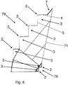
Figure 8 diagrammatically shows a section of another variant of a conduit according to the invention; -
Figure 9 diagrammatically shows a section of another variant of a conduit according to the invention; -
Figure 10 shows the view inFigure 5 , with a diagrammatic depiction of the reflection of the sound waves along the conduit of the invention. - The same reference numerals in the drawings identify the same elements or components, or similar elements or components.
- With reference to the drawings, some examples are described of a
fume discharge conduit 1 according to the invention. - The
fume discharge conduit 1 is soundproof and is adapted to be arranged between a ventilation system (not shown) and a chimney 20 (partially shown inFigure 3 ). - The
conduit 1 is particularly adapted to be connected to the ventilation system and to thechimney 20. One ormore conduits 1, for example one, two, three or fourconduits 1, can be connected to thechimney 20. Theconduit 1 comprises aninlet section 61, through which the fumes are emitted intoconduit 1, and anoutlet section 71, from which the fumes leave theconduit 1 to be introduced into thechimney 20. In particular, theconduit 1 is a suction branch of thechimney 20. - In all the embodiments of the invention, the
conduit 1 defines a fume path therein, and at least one side surface ofconduit 1 is provided with at least twoprotrusions 2. Eachprotrusion 2 internally defines a respective step-shapedrecess 3, whereby the path is provided with at least two step-shapedrecesses 3. The step-shapedrecesses 3 are advantageously adapted to reflect sound waves, in particular generated by the ventilation system, which propagate along the fume path defined by theconduit 1. -
Figure 10 diagrammatically shows the upward sound waves and the sound waves which are advantageously absorbed and/or reflected by thesteps 3, in particular by thewalls 4 and/or by thewalls 5. - The step shape of each
recess 3 indeed is defined by twowalls 4, 5 (also called first walls) which are incident at afirst end thereof 41, 51 (Figure 1 ). For eachrecess 3, also calledstep 3, at least one wall of the twowalls wall 4 and/or thewall 5 are coated with sound absorbing material. In particular, the surface, inside theconduit 1, of thewall 4 and/or of thewall 5 is coated with sound absorbing material. - The sound absorbing material preferably comprises or consists of expanded clay, in particular expanded clay granules, or steel wool or mineral wool or polyester fluff. For each
recess 3, theend 41 of thewall 4 is preferably joined, in particular directly joined, to theend 51 ofwall 5. - More generally, the
recesses 3 preferably are consecutive to one another, preferably adjacent to one another. - According to the number of
protrusions 2, at least onewall 5 of oneprotrusion 2 is preferably joined to arespective wall 4 of theconsecutive protrusion 2. - In particular, for each
recess 3, thewall 4 and thewall 5 are mutually inclined. Thewall 4, withwall 5, forms an angle, for example but not exclusively equal to about 90°. Preferably, but not exclusively, thewalls 4 are parallel to one another and/or thewalls 5 are parallel to one another. - Preferably, said at least two
protrusions 2 are externally step-shaped. - With particular reference to
Figure 1 , theconduit 1 comprises two mutuallyinclined stretches stretches stretch 72 which is preferably curved. The connectingstretch 72 preferably is a portion of thestretch 7. - The
stretch 6 of theconduit 1 is adapted to be connected to the ventilation system. Theinlet section 61 of theconduit 1 is preferably delimited by thestretch 6. - The
stretch 6 defines a longitudinal axis X. The longitudinal axis X preferably crosses theinlet section 61. - The
stretch 7 of theconduit 1 is adapted to be connected to theoutlet chimney 20. In particular, theoutlet section 71 of theconduit 1 is preferably delimited by thestretch 7. - The
stretch 7 defines a longitudinal axis Y, which is inclined with respect to the longitudinal axis X of thestretch 6. The longitudinal axis Y preferably crosses theoutlet section 71. - At least the
upper surface 79 of thestretch 7 is provided with at least twoprotrusions 2, for example threeprotrusions 2, as shown inFigure 1 , or fourprotrusions 2, as shown inFigures 3, 4 ,5, 6 ,8 ,9, 10 , in which the fourth protrusion preferably is at the upper surface of the connectingstretch 72. - The
upper surface 79 of thestretch 7 is, in particular, the surface which is distal from thechimney 20 when theconduit 1 is connected to thechimney 20. Preferably, at least part of theupper surface 79 is substantially opposed to theoutlet section 71. Theprotrusions 2 are preferably arranged in sequence, for example in sequence substantially along the axis Y. - The
stretch 7 preferably has a circular or polygonal cross-section. The cross-section of thestretch 7 can, for example, be substantially quadrangular, in particular in the variants shown inFigures 8 and9 . -
Figure 8 shows a variant in which also thelower surface 78 of thestretch 7 is provided withprotrusions 2, for example twoprotrusions 2. - The
lower surface 78 preferably is close to, for example adjacent to, the outlet section of theconduit 1. - In the variant shown in
Figure 8 , eachprotrusion 2 internally defines a respective step-shapedrecess 3, substantially as described above. Theprotrusions 2 protrude outward so as not to substantially alter the flow rate of the fumes. - In the variant shown in
Figure 9 , in addition to theupper surface 79, also theside surface 76 and theside surface 77 of theconduit 1 are each provided with at least twoprotrusions 2. Eachprotrusion 2 of the side surfaces 76, 77 internally defines a respective step-shapedrecess 3, substantially as described above. - For example, four
protrusions 2 are provided for eachside surface side surface 76 and theside surface 77 preferably are opposite to each other. - In all the embodiments, a panel 8 (
Figures 6 and 7 ) to improve the soundproofing is preferably included, the panel being provided with a plurality ofholes 9, in particular through holes, and resting on second ends 42, 52 of the twofirst walls recess 3 together with twosecond side walls 10 which are parallel to each other and transversal, e.g. orthogonal, to thewalls Figure 6 shows only one of the twowalls 10 for each step-shapedrecess 3. - In the variant shown in
Figures 6 and 7 , thepanel 8 particularly rests on theends steps 3 of theupper surface 79 ofconduit 1. - The
panel 8 is preferably made of metal, in particular metal sheet. The metal sheet is preferably coated with a sound absorbing material. The sound absorbing material preferably comprises or consists of expanded clay, in particular expanded clay granules, or steel wool or mineral wool or polyester fluff. The sound absorbing material can be the same sound absorbing material with which thewalls 4 and/or 5 are coated or a different sound absorbing material. - To obtain better soundproofing performance, the
panel 8 preferably has a percentage ratio of the area of the plurality of holes 9 (intended as the sum of the areas of holes) to the area of thesolid part 11 of thepanel 8 which is less than 50%, preferably from 25 to 35%. - A
single panel 8 is preferably provided resting on the second ends 42, 52 of the twowalls recess 3. - As already mentioned, the
stretch 7 of theconduit 1 preferably has a circular or polygonal cross-section, for example a quadrangular cross-section. In order to improve the soundproofing without affecting the flow rate of the fumes, bothwalls first side 12', 12" (Figure 3 ) with a length less than the average diameter, preferably less than half the average diameter, of the stretch 7 (when the latter has a circular cross-section), or less than the width, preferably less than half the width, of the stretch 7 (when the latter has polygonal cross-section). - When the
stretch 7 of theconduit 1 has a quadrangular cross-section, bothwalls recess 3 preferably have saidfirst side 12', 12" with a shorter length than the width of thestretch 7, preferably less than half the width of thestretch 7, and preferably a second side with a length substantially equal to the width of thesecond stretch 7. The side 12' of thewall 4 preferably defines the depth of thestep 3, and theside 12" of thewall 5 preferably defines the height of thestep 3, or of theprotrusion 2. - The invention also relates to a
fume outlet chimney 20 of a steel plant, thechimney 20 being connected, in particular at the bottom or at the side, to at least onefume discharge conduit 1, for example one, two, three, four ormore conduits 1.
Claims (13)
- A soundproof fume discharge conduit (1), adapted to be arranged between a ventilation system and an outlet chimney (20), the conduit (1) defining a fume path therein,
wherein at least one side surface (76, 77, 78, 79) of the conduit (1) is provided with at least two protrusions (2), each protrusion (2) internally defining a respective step-shaped recess (3), whereby the path is provided with at least two step-shaped recesses (3) adapted to reflect sound waves propagating along the path,
wherein the step shape of each recess (3) is defined by two first walls (4, 5), which are incident at a first end (41, 51) thereof, and at least one wall of the two first walls (4, 5) is coated with a first sound absorbing material. - A conduit according to claim 1, wherein said at least two protrusions (2) are externally step-shaped.
- A conduit according to claim 1 or 2, wherein there are provided a first stretch (6) of the conduit, defining a first longitudinal axis (X) and adapted to be connected to the ventilation system, and a second stretch (7) of the conduit (1) defining a second longitudinal axis (Y) inclined with respect to the first longitudinal axis (X) and adapted to be connected to the outlet chimney (20); and wherein said at least one side surface of the conduit is the upper surface (79) of the second stretch (7).
- A conduit according to claim 3, wherein said at least two protrusions (2) are also provided on the lower surface (78) and/or on the side surfaces (76, 77) of the second stretch (7); preferably, wherein the second stretch (7) of the conduit has a polygonal section, in particular a quadrangular section.
- A conduit according to any one of the preceding claims, wherein a panel (8) is included, provided with a plurality of holes (9) and resting on second ends (42, 52) of the two first walls (4, 5), opposed to the first ends (41, 51), thus delimiting the volume of the step-shaped recess (3) together with two second side walls (10) which are parallel to each other and transversal to said two first walls (4, 5).
- A conduit according to claim 5, wherein a single panel (8) is provided resting on the second ends (42, 52) of the two first walls (4, 5) of each step-shaped recess (3).
- A conduit according to claim 5 or 6, wherein said panel (8) is made of metal sheet coated with a second sound absorbing material.
- A conduit according to claim 5 or 6 or 7, wherein said panel (8) has a percentage ratio of the area of the plurality of holes (9) to the area of the solid part (11) of the panel (8) which is less than 50%, preferably from 25 to 35%.
- A conduit according to claim 7 or 8, wherein said second sound absorbing material is selected from the following: expanded clay, in particular expanded clay granules; steel wool; mineral wool; preferably wherein said second sound absorbing material is the same as the first sound absorbing material.
- A conduit according to any one of the preceding claims, wherein the second stretch (7) of the conduit has a circular or polygonal cross-section; and wherein both the first walls (4, 5) of at least one step-shaped recess (3) have a first side (12', 12") with a shorter length than half of the average diameter of the second stretch (7) in the case of a circular section or than half of the width of the second stretch (7) in the case of a polygonal section.
- A conduit according to claim 10, wherein the second stretch (7) of the conduit has a quadrangular section; and wherein both the first walls (4, 5) of at least one step-shaped recess (3) have said first side (12', 12") with a shorter length than half of the width of the second stretch (7) and a second side with a length which is substantially equal to the width of the second stretch (7).
- A conduit according to any one of the preceding claims, wherein said first sound absorbing material is selected from the following: expanded clay, in particular expanded clay granules; steel wool; mineral wool.
- A fume outlet chimney (20) of a steel plant, said chimney being connected, in particular at the bottom, to at least one fume discharge conduit (1) according to any one of the preceding claims.
Applications Claiming Priority (1)
| Application Number | Priority Date | Filing Date | Title |
|---|---|---|---|
| IT102019000018695A IT201900018695A1 (en) | 2019-10-14 | 2019-10-14 | SOUNDPROOF SMOKE EXHAUST DUCT |
Publications (2)
| Publication Number | Publication Date |
|---|---|
| EP3809043A1 true EP3809043A1 (en) | 2021-04-21 |
| EP3809043B1 EP3809043B1 (en) | 2022-08-03 |
Family
ID=69570763
Family Applications (1)
| Application Number | Title | Priority Date | Filing Date |
|---|---|---|---|
| EP20201665.5A Active EP3809043B1 (en) | 2019-10-14 | 2020-10-14 | Soundproof fume discharge conduit |
Country Status (4)
| Country | Link |
|---|---|
| US (1) | US11634904B2 (en) |
| EP (1) | EP3809043B1 (en) |
| KR (1) | KR102496986B1 (en) |
| IT (1) | IT201900018695A1 (en) |
Citations (4)
| Publication number | Priority date | Publication date | Assignee | Title |
|---|---|---|---|---|
| DE9316608U1 (en) * | 1993-10-13 | 1995-02-16 | Ruhland, Manfred, 81929 München | Steel chimney connection |
| US6059070A (en) * | 1997-02-07 | 2000-05-09 | Danieli & Officine Meccaniche Spa | Soundproofed conduit to discharge fumes |
| DE202007017770U1 (en) * | 2007-12-20 | 2009-04-23 | Kutzner + Weber Gmbh | Gas discharge arrangement |
| CN108006681A (en) * | 2017-12-30 | 2018-05-08 | 江苏永益环保科技有限公司 | Noise reduction rain-proof draining blast cap |
Family Cites Families (15)
| Publication number | Priority date | Publication date | Assignee | Title |
|---|---|---|---|---|
| US1832741A (en) * | 1929-07-18 | 1931-11-17 | Fred J Sersen | Means for acoustical correction |
| US4303144A (en) * | 1979-12-21 | 1981-12-01 | Lockheed Corporation | Apparatus for the retroreflection of sound |
| US4356880A (en) * | 1980-07-28 | 1982-11-02 | Downs James W | Acoustical reflectors |
| DE4233312A1 (en) * | 1992-10-03 | 1994-04-07 | Ilyas Dipl Ing Oezpolat | Vapour exhaust hood with collector housing and duct to fan - has elbow, forming duct deflector, fitted with sound damping insert on outside. |
| GB2275545A (en) * | 1993-02-24 | 1994-08-31 | Siemens Ag | Diverting fluid flow |
| JPH1082505A (en) * | 1996-09-06 | 1998-03-31 | Matsushita Electric Ind Co Ltd | Combustion equipment |
| AUPP015097A0 (en) * | 1997-11-03 | 1997-11-27 | Resmed Limited | A mounting body |
| JPH11182774A (en) * | 1997-12-18 | 1999-07-06 | Tokai Rubber Ind Ltd | Sound insulation for water pipes |
| DE19804567C2 (en) * | 1998-02-05 | 2003-12-11 | Woco Franz Josef Wolf & Co Gmbh | Surface absorber for sound waves and use |
| JP3536201B2 (en) * | 1999-04-22 | 2004-06-07 | 株式会社アルム | Sound absorbing panel |
| FR2793825B1 (en) * | 1999-05-18 | 2005-09-30 | Robert Dubourg | ABSORPTION SOUNDS |
| US8087491B2 (en) * | 2010-01-08 | 2012-01-03 | General Electric Company | Vane type silencers in elbow for gas turbine |
| JP5899017B2 (en) * | 2012-03-22 | 2016-04-06 | 本田技研工業株式会社 | Motorcycle exhaust system |
| US9290274B2 (en) * | 2014-06-02 | 2016-03-22 | Mra Systems, Inc. | Acoustically attenuating sandwich panel constructions |
| US11398214B2 (en) * | 2018-12-14 | 2022-07-26 | Rohr, Inc. | Forming a structured panel with one or more structural reinforcements |
-
2019
- 2019-10-14 IT IT102019000018695A patent/IT201900018695A1/en unknown
-
2020
- 2020-10-13 US US17/069,192 patent/US11634904B2/en active Active
- 2020-10-14 EP EP20201665.5A patent/EP3809043B1/en active Active
- 2020-10-14 KR KR1020200132496A patent/KR102496986B1/en active Active
Patent Citations (4)
| Publication number | Priority date | Publication date | Assignee | Title |
|---|---|---|---|---|
| DE9316608U1 (en) * | 1993-10-13 | 1995-02-16 | Ruhland, Manfred, 81929 München | Steel chimney connection |
| US6059070A (en) * | 1997-02-07 | 2000-05-09 | Danieli & Officine Meccaniche Spa | Soundproofed conduit to discharge fumes |
| DE202007017770U1 (en) * | 2007-12-20 | 2009-04-23 | Kutzner + Weber Gmbh | Gas discharge arrangement |
| CN108006681A (en) * | 2017-12-30 | 2018-05-08 | 江苏永益环保科技有限公司 | Noise reduction rain-proof draining blast cap |
Also Published As
| Publication number | Publication date |
|---|---|
| KR20210044713A (en) | 2021-04-23 |
| EP3809043B1 (en) | 2022-08-03 |
| IT201900018695A1 (en) | 2021-04-14 |
| US11634904B2 (en) | 2023-04-25 |
| US20210108407A1 (en) | 2021-04-15 |
| KR102496986B1 (en) | 2023-02-06 |
Similar Documents
| Publication | Publication Date | Title |
|---|---|---|
| US8087491B2 (en) | Vane type silencers in elbow for gas turbine | |
| US5518451A (en) | Clean room system | |
| EP0940585B1 (en) | Suction elbow provided with built-in guide blades | |
| US6431974B1 (en) | Acoustic wind band | |
| EP1657451A1 (en) | A duct fan | |
| RU2426948C2 (en) | Transverse wall of combustion chamber, which contains many perforated holes, combustion chamber of gas turbine engine, and gas turbine engine | |
| EP3809043B1 (en) | Soundproof fume discharge conduit | |
| US5196653A (en) | Muffler for air powered turbine drive | |
| US7350620B2 (en) | Compact silencer | |
| CN118831231A (en) | Artificial respirator | |
| KR101614072B1 (en) | Reactive low static pressure silencer | |
| JP4982165B2 (en) | Silencer | |
| US7806229B2 (en) | Fan powered silencing terminal unit | |
| CN105781682B (en) | Wind Volume composite muffler | |
| US6059070A (en) | Soundproofed conduit to discharge fumes | |
| CN113795716B (en) | Fluid Drain Pipe Assemblies | |
| KR102820030B1 (en) | A Noise Reductor For Noise Reduction Of A Fluid Through Ducts | |
| CN222924571U (en) | Suction muffler and compressor | |
| KR850000644B1 (en) | Exhaust apparatus in jet engine testing room | |
| SU1703917A1 (en) | Swivel gas duct | |
| CN217464900U (en) | Box and gas heater | |
| CN213272874U (en) | Muffler device and full heat exchange system | |
| JP7395176B2 (en) | chimney | |
| JP2582217B2 (en) | Sound reduction distributor for high-speed duct | |
| RU2222745C2 (en) | Gas line noise damping rectangular bend |
Legal Events
| Date | Code | Title | Description |
|---|---|---|---|
| PUAI | Public reference made under article 153(3) epc to a published international application that has entered the european phase |
Free format text: ORIGINAL CODE: 0009012 |
|
| STAA | Information on the status of an ep patent application or granted ep patent |
Free format text: STATUS: THE APPLICATION HAS BEEN PUBLISHED |
|
| AK | Designated contracting states |
Kind code of ref document: A1 Designated state(s): AL AT BE BG CH CY CZ DE DK EE ES FI FR GB GR HR HU IE IS IT LI LT LU LV MC MK MT NL NO PL PT RO RS SE SI SK SM TR |
|
| AX | Request for extension of the european patent |
Extension state: BA ME |
|
| STAA | Information on the status of an ep patent application or granted ep patent |
Free format text: STATUS: REQUEST FOR EXAMINATION WAS MADE |
|
| 17P | Request for examination filed |
Effective date: 20211020 |
|
| RBV | Designated contracting states (corrected) |
Designated state(s): AL AT BE BG CH CY CZ DE DK EE ES FI FR GB GR HR HU IE IS IT LI LT LU LV MC MK MT NL NO PL PT RO RS SE SI SK SM TR |
|
| GRAP | Despatch of communication of intention to grant a patent |
Free format text: ORIGINAL CODE: EPIDOSNIGR1 |
|
| STAA | Information on the status of an ep patent application or granted ep patent |
Free format text: STATUS: GRANT OF PATENT IS INTENDED |
|
| INTG | Intention to grant announced |
Effective date: 20220223 |
|
| GRAS | Grant fee paid |
Free format text: ORIGINAL CODE: EPIDOSNIGR3 |
|
| GRAA | (expected) grant |
Free format text: ORIGINAL CODE: 0009210 |
|
| STAA | Information on the status of an ep patent application or granted ep patent |
Free format text: STATUS: THE PATENT HAS BEEN GRANTED |
|
| AK | Designated contracting states |
Kind code of ref document: B1 Designated state(s): AL AT BE BG CH CY CZ DE DK EE ES FI FR GB GR HR HU IE IS IT LI LT LU LV MC MK MT NL NO PL PT RO RS SE SI SK SM TR |
|
| REG | Reference to a national code |
Ref country code: AT Ref legal event code: REF Ref document number: 1509023 Country of ref document: AT Kind code of ref document: T Effective date: 20220815 Ref country code: CH Ref legal event code: EP |
|
| REG | Reference to a national code |
Ref country code: DE Ref legal event code: R096 Ref document number: 602020004326 Country of ref document: DE |
|
| REG | Reference to a national code |
Ref country code: IE Ref legal event code: FG4D |
|
| REG | Reference to a national code |
Ref country code: SE Ref legal event code: TRGR |
|
| REG | Reference to a national code |
Ref country code: LT Ref legal event code: MG9D |
|
| REG | Reference to a national code |
Ref country code: NL Ref legal event code: MP Effective date: 20220803 |
|
| PG25 | Lapsed in a contracting state [announced via postgrant information from national office to epo] |
Ref country code: RS Free format text: LAPSE BECAUSE OF FAILURE TO SUBMIT A TRANSLATION OF THE DESCRIPTION OR TO PAY THE FEE WITHIN THE PRESCRIBED TIME-LIMIT Effective date: 20220803 Ref country code: PT Free format text: LAPSE BECAUSE OF FAILURE TO SUBMIT A TRANSLATION OF THE DESCRIPTION OR TO PAY THE FEE WITHIN THE PRESCRIBED TIME-LIMIT Effective date: 20221205 Ref country code: NO Free format text: LAPSE BECAUSE OF FAILURE TO SUBMIT A TRANSLATION OF THE DESCRIPTION OR TO PAY THE FEE WITHIN THE PRESCRIBED TIME-LIMIT Effective date: 20221103 Ref country code: NL Free format text: LAPSE BECAUSE OF FAILURE TO SUBMIT A TRANSLATION OF THE DESCRIPTION OR TO PAY THE FEE WITHIN THE PRESCRIBED TIME-LIMIT Effective date: 20220803 Ref country code: LV Free format text: LAPSE BECAUSE OF FAILURE TO SUBMIT A TRANSLATION OF THE DESCRIPTION OR TO PAY THE FEE WITHIN THE PRESCRIBED TIME-LIMIT Effective date: 20220803 Ref country code: LT Free format text: LAPSE BECAUSE OF FAILURE TO SUBMIT A TRANSLATION OF THE DESCRIPTION OR TO PAY THE FEE WITHIN THE PRESCRIBED TIME-LIMIT Effective date: 20220803 Ref country code: FI Free format text: LAPSE BECAUSE OF FAILURE TO SUBMIT A TRANSLATION OF THE DESCRIPTION OR TO PAY THE FEE WITHIN THE PRESCRIBED TIME-LIMIT Effective date: 20220803 Ref country code: ES Free format text: LAPSE BECAUSE OF FAILURE TO SUBMIT A TRANSLATION OF THE DESCRIPTION OR TO PAY THE FEE WITHIN THE PRESCRIBED TIME-LIMIT Effective date: 20220803 |
|
| PG25 | Lapsed in a contracting state [announced via postgrant information from national office to epo] |
Ref country code: PL Free format text: LAPSE BECAUSE OF FAILURE TO SUBMIT A TRANSLATION OF THE DESCRIPTION OR TO PAY THE FEE WITHIN THE PRESCRIBED TIME-LIMIT Effective date: 20220803 Ref country code: IS Free format text: LAPSE BECAUSE OF FAILURE TO SUBMIT A TRANSLATION OF THE DESCRIPTION OR TO PAY THE FEE WITHIN THE PRESCRIBED TIME-LIMIT Effective date: 20221203 Ref country code: HR Free format text: LAPSE BECAUSE OF FAILURE TO SUBMIT A TRANSLATION OF THE DESCRIPTION OR TO PAY THE FEE WITHIN THE PRESCRIBED TIME-LIMIT Effective date: 20220803 Ref country code: GR Free format text: LAPSE BECAUSE OF FAILURE TO SUBMIT A TRANSLATION OF THE DESCRIPTION OR TO PAY THE FEE WITHIN THE PRESCRIBED TIME-LIMIT Effective date: 20221104 |
|
| PG25 | Lapsed in a contracting state [announced via postgrant information from national office to epo] |
Ref country code: SM Free format text: LAPSE BECAUSE OF FAILURE TO SUBMIT A TRANSLATION OF THE DESCRIPTION OR TO PAY THE FEE WITHIN THE PRESCRIBED TIME-LIMIT Effective date: 20220803 Ref country code: RO Free format text: LAPSE BECAUSE OF FAILURE TO SUBMIT A TRANSLATION OF THE DESCRIPTION OR TO PAY THE FEE WITHIN THE PRESCRIBED TIME-LIMIT Effective date: 20220803 Ref country code: DK Free format text: LAPSE BECAUSE OF FAILURE TO SUBMIT A TRANSLATION OF THE DESCRIPTION OR TO PAY THE FEE WITHIN THE PRESCRIBED TIME-LIMIT Effective date: 20220803 Ref country code: CZ Free format text: LAPSE BECAUSE OF FAILURE TO SUBMIT A TRANSLATION OF THE DESCRIPTION OR TO PAY THE FEE WITHIN THE PRESCRIBED TIME-LIMIT Effective date: 20220803 |
|
| REG | Reference to a national code |
Ref country code: DE Ref legal event code: R097 Ref document number: 602020004326 Country of ref document: DE |
|
| PG25 | Lapsed in a contracting state [announced via postgrant information from national office to epo] |
Ref country code: SK Free format text: LAPSE BECAUSE OF FAILURE TO SUBMIT A TRANSLATION OF THE DESCRIPTION OR TO PAY THE FEE WITHIN THE PRESCRIBED TIME-LIMIT Effective date: 20220803 Ref country code: MC Free format text: LAPSE BECAUSE OF FAILURE TO SUBMIT A TRANSLATION OF THE DESCRIPTION OR TO PAY THE FEE WITHIN THE PRESCRIBED TIME-LIMIT Effective date: 20220803 Ref country code: EE Free format text: LAPSE BECAUSE OF FAILURE TO SUBMIT A TRANSLATION OF THE DESCRIPTION OR TO PAY THE FEE WITHIN THE PRESCRIBED TIME-LIMIT Effective date: 20220803 |
|
| PLBE | No opposition filed within time limit |
Free format text: ORIGINAL CODE: 0009261 |
|
| STAA | Information on the status of an ep patent application or granted ep patent |
Free format text: STATUS: NO OPPOSITION FILED WITHIN TIME LIMIT |
|
| REG | Reference to a national code |
Ref country code: BE Ref legal event code: MM Effective date: 20221031 |
|
| PG25 | Lapsed in a contracting state [announced via postgrant information from national office to epo] |
Ref country code: LU Free format text: LAPSE BECAUSE OF NON-PAYMENT OF DUE FEES Effective date: 20221014 Ref country code: AL Free format text: LAPSE BECAUSE OF FAILURE TO SUBMIT A TRANSLATION OF THE DESCRIPTION OR TO PAY THE FEE WITHIN THE PRESCRIBED TIME-LIMIT Effective date: 20220803 |
|
| 26N | No opposition filed |
Effective date: 20230504 |
|
| PG25 | Lapsed in a contracting state [announced via postgrant information from national office to epo] |
Ref country code: SI Free format text: LAPSE BECAUSE OF FAILURE TO SUBMIT A TRANSLATION OF THE DESCRIPTION OR TO PAY THE FEE WITHIN THE PRESCRIBED TIME-LIMIT Effective date: 20220803 |
|
| PG25 | Lapsed in a contracting state [announced via postgrant information from national office to epo] |
Ref country code: BE Free format text: LAPSE BECAUSE OF NON-PAYMENT OF DUE FEES Effective date: 20221031 |
|
| PG25 | Lapsed in a contracting state [announced via postgrant information from national office to epo] |
Ref country code: IE Free format text: LAPSE BECAUSE OF NON-PAYMENT OF DUE FEES Effective date: 20221014 |
|
| PG25 | Lapsed in a contracting state [announced via postgrant information from national office to epo] |
Ref country code: CY Free format text: LAPSE BECAUSE OF FAILURE TO SUBMIT A TRANSLATION OF THE DESCRIPTION OR TO PAY THE FEE WITHIN THE PRESCRIBED TIME-LIMIT Effective date: 20220803 |
|
| PG25 | Lapsed in a contracting state [announced via postgrant information from national office to epo] |
Ref country code: MK Free format text: LAPSE BECAUSE OF FAILURE TO SUBMIT A TRANSLATION OF THE DESCRIPTION OR TO PAY THE FEE WITHIN THE PRESCRIBED TIME-LIMIT Effective date: 20220803 |
|
| REG | Reference to a national code |
Ref country code: AT Ref legal event code: UEP Ref document number: 1509023 Country of ref document: AT Kind code of ref document: T Effective date: 20220803 |
|
| PG25 | Lapsed in a contracting state [announced via postgrant information from national office to epo] |
Ref country code: HU Free format text: LAPSE BECAUSE OF FAILURE TO SUBMIT A TRANSLATION OF THE DESCRIPTION OR TO PAY THE FEE WITHIN THE PRESCRIBED TIME-LIMIT; INVALID AB INITIO Effective date: 20201014 Ref country code: BG Free format text: LAPSE BECAUSE OF FAILURE TO SUBMIT A TRANSLATION OF THE DESCRIPTION OR TO PAY THE FEE WITHIN THE PRESCRIBED TIME-LIMIT Effective date: 20220803 |
|
| PG25 | Lapsed in a contracting state [announced via postgrant information from national office to epo] |
Ref country code: MT Free format text: LAPSE BECAUSE OF FAILURE TO SUBMIT A TRANSLATION OF THE DESCRIPTION OR TO PAY THE FEE WITHIN THE PRESCRIBED TIME-LIMIT Effective date: 20220803 |
|
| PGFP | Annual fee paid to national office [announced via postgrant information from national office to epo] |
Ref country code: TR Payment date: 20250925 Year of fee payment: 6 |
|
| REG | Reference to a national code |
Ref country code: CH Ref legal event code: U11 Free format text: ST27 STATUS EVENT CODE: U-0-0-U10-U11 (AS PROVIDED BY THE NATIONAL OFFICE) Effective date: 20251101 |
|
| PGFP | Annual fee paid to national office [announced via postgrant information from national office to epo] |
Ref country code: DE Payment date: 20251029 Year of fee payment: 6 |
|
| PGFP | Annual fee paid to national office [announced via postgrant information from national office to epo] |
Ref country code: GB Payment date: 20251027 Year of fee payment: 6 |
|
| PGFP | Annual fee paid to national office [announced via postgrant information from national office to epo] |
Ref country code: AT Payment date: 20251029 Year of fee payment: 6 |
|
| PGFP | Annual fee paid to national office [announced via postgrant information from national office to epo] |
Ref country code: IT Payment date: 20251021 Year of fee payment: 6 |
|
| PGFP | Annual fee paid to national office [announced via postgrant information from national office to epo] |
Ref country code: FR Payment date: 20251027 Year of fee payment: 6 |
|
| PGFP | Annual fee paid to national office [announced via postgrant information from national office to epo] |
Ref country code: SE Payment date: 20251027 Year of fee payment: 6 Ref country code: CH Payment date: 20251101 Year of fee payment: 6 |