EP3809032B1 - Pipe with an outer wrap - Google Patents
Pipe with an outer wrap Download PDFInfo
- Publication number
- EP3809032B1 EP3809032B1 EP20213943.2A EP20213943A EP3809032B1 EP 3809032 B1 EP3809032 B1 EP 3809032B1 EP 20213943 A EP20213943 A EP 20213943A EP 3809032 B1 EP3809032 B1 EP 3809032B1
- Authority
- EP
- European Patent Office
- Prior art keywords
- wrap
- pipe
- type
- plastic
- fiber
- Prior art date
- Legal status (The legal status is an assumption and is not a legal conclusion. Google has not performed a legal analysis and makes no representation as to the accuracy of the status listed.)
- Active
Links
Images

Classifications
-
- F—MECHANICAL ENGINEERING; LIGHTING; HEATING; WEAPONS; BLASTING
- F16—ENGINEERING ELEMENTS AND UNITS; GENERAL MEASURES FOR PRODUCING AND MAINTAINING EFFECTIVE FUNCTIONING OF MACHINES OR INSTALLATIONS; THERMAL INSULATION IN GENERAL
- F16L—PIPES; JOINTS OR FITTINGS FOR PIPES; SUPPORTS FOR PIPES, CABLES OR PROTECTIVE TUBING; MEANS FOR THERMAL INSULATION IN GENERAL
- F16L9/00—Rigid pipes
- F16L9/12—Rigid pipes of plastics with or without reinforcement
- F16L9/127—Rigid pipes of plastics with or without reinforcement the walls consisting of a single layer
-
- B—PERFORMING OPERATIONS; TRANSPORTING
- B29—WORKING OF PLASTICS; WORKING OF SUBSTANCES IN A PLASTIC STATE IN GENERAL
- B29C—SHAPING OR JOINING OF PLASTICS; SHAPING OF MATERIAL IN A PLASTIC STATE, NOT OTHERWISE PROVIDED FOR; AFTER-TREATMENT OF THE SHAPED PRODUCTS, e.g. REPAIRING
- B29C48/00—Extrusion moulding, i.e. expressing the moulding material through a die or nozzle which imparts the desired form; Apparatus therefor
- B29C48/001—Combinations of extrusion moulding with other shaping operations
- B29C48/0018—Combinations of extrusion moulding with other shaping operations combined with shaping by orienting, stretching or shrinking, e.g. film blowing
-
- B—PERFORMING OPERATIONS; TRANSPORTING
- B29—WORKING OF PLASTICS; WORKING OF SUBSTANCES IN A PLASTIC STATE IN GENERAL
- B29C—SHAPING OR JOINING OF PLASTICS; SHAPING OF MATERIAL IN A PLASTIC STATE, NOT OTHERWISE PROVIDED FOR; AFTER-TREATMENT OF THE SHAPED PRODUCTS, e.g. REPAIRING
- B29C48/00—Extrusion moulding, i.e. expressing the moulding material through a die or nozzle which imparts the desired form; Apparatus therefor
- B29C48/001—Combinations of extrusion moulding with other shaping operations
- B29C48/0021—Combinations of extrusion moulding with other shaping operations combined with joining, lining or laminating
-
- B—PERFORMING OPERATIONS; TRANSPORTING
- B29—WORKING OF PLASTICS; WORKING OF SUBSTANCES IN A PLASTIC STATE IN GENERAL
- B29C—SHAPING OR JOINING OF PLASTICS; SHAPING OF MATERIAL IN A PLASTIC STATE, NOT OTHERWISE PROVIDED FOR; AFTER-TREATMENT OF THE SHAPED PRODUCTS, e.g. REPAIRING
- B29C48/00—Extrusion moulding, i.e. expressing the moulding material through a die or nozzle which imparts the desired form; Apparatus therefor
- B29C48/03—Extrusion moulding, i.e. expressing the moulding material through a die or nozzle which imparts the desired form; Apparatus therefor characterised by the shape of the extruded material at extrusion
- B29C48/07—Flat, e.g. panels
-
- B—PERFORMING OPERATIONS; TRANSPORTING
- B29—WORKING OF PLASTICS; WORKING OF SUBSTANCES IN A PLASTIC STATE IN GENERAL
- B29C—SHAPING OR JOINING OF PLASTICS; SHAPING OF MATERIAL IN A PLASTIC STATE, NOT OTHERWISE PROVIDED FOR; AFTER-TREATMENT OF THE SHAPED PRODUCTS, e.g. REPAIRING
- B29C48/00—Extrusion moulding, i.e. expressing the moulding material through a die or nozzle which imparts the desired form; Apparatus therefor
- B29C48/03—Extrusion moulding, i.e. expressing the moulding material through a die or nozzle which imparts the desired form; Apparatus therefor characterised by the shape of the extruded material at extrusion
- B29C48/09—Articles with cross-sections having partially or fully enclosed cavities, e.g. pipes or channels
-
- B—PERFORMING OPERATIONS; TRANSPORTING
- B29—WORKING OF PLASTICS; WORKING OF SUBSTANCES IN A PLASTIC STATE IN GENERAL
- B29C—SHAPING OR JOINING OF PLASTICS; SHAPING OF MATERIAL IN A PLASTIC STATE, NOT OTHERWISE PROVIDED FOR; AFTER-TREATMENT OF THE SHAPED PRODUCTS, e.g. REPAIRING
- B29C48/00—Extrusion moulding, i.e. expressing the moulding material through a die or nozzle which imparts the desired form; Apparatus therefor
- B29C48/03—Extrusion moulding, i.e. expressing the moulding material through a die or nozzle which imparts the desired form; Apparatus therefor characterised by the shape of the extruded material at extrusion
- B29C48/131—Curved articles
-
- B—PERFORMING OPERATIONS; TRANSPORTING
- B29—WORKING OF PLASTICS; WORKING OF SUBSTANCES IN A PLASTIC STATE IN GENERAL
- B29C—SHAPING OR JOINING OF PLASTICS; SHAPING OF MATERIAL IN A PLASTIC STATE, NOT OTHERWISE PROVIDED FOR; AFTER-TREATMENT OF THE SHAPED PRODUCTS, e.g. REPAIRING
- B29C48/00—Extrusion moulding, i.e. expressing the moulding material through a die or nozzle which imparts the desired form; Apparatus therefor
- B29C48/15—Extrusion moulding, i.e. expressing the moulding material through a die or nozzle which imparts the desired form; Apparatus therefor incorporating preformed parts or layers, e.g. extrusion moulding around inserts
- B29C48/151—Coating hollow articles
-
- B—PERFORMING OPERATIONS; TRANSPORTING
- B29—WORKING OF PLASTICS; WORKING OF SUBSTANCES IN A PLASTIC STATE IN GENERAL
- B29C—SHAPING OR JOINING OF PLASTICS; SHAPING OF MATERIAL IN A PLASTIC STATE, NOT OTHERWISE PROVIDED FOR; AFTER-TREATMENT OF THE SHAPED PRODUCTS, e.g. REPAIRING
- B29C48/00—Extrusion moulding, i.e. expressing the moulding material through a die or nozzle which imparts the desired form; Apparatus therefor
- B29C48/25—Component parts, details or accessories; Auxiliary operations
- B29C48/285—Feeding the extrusion material to the extruder
- B29C48/288—Feeding the extrusion material to the extruder in solid form, e.g. powder or granules
- B29C48/2883—Feeding the extrusion material to the extruder in solid form, e.g. powder or granules of preformed parts, e.g. inserts, retaining their shape during the extrusion process
-
- B—PERFORMING OPERATIONS; TRANSPORTING
- B29—WORKING OF PLASTICS; WORKING OF SUBSTANCES IN A PLASTIC STATE IN GENERAL
- B29C—SHAPING OR JOINING OF PLASTICS; SHAPING OF MATERIAL IN A PLASTIC STATE, NOT OTHERWISE PROVIDED FOR; AFTER-TREATMENT OF THE SHAPED PRODUCTS, e.g. REPAIRING
- B29C48/00—Extrusion moulding, i.e. expressing the moulding material through a die or nozzle which imparts the desired form; Apparatus therefor
- B29C48/25—Component parts, details or accessories; Auxiliary operations
- B29C48/285—Feeding the extrusion material to the extruder
- B29C48/288—Feeding the extrusion material to the extruder in solid form, e.g. powder or granules
- B29C48/2886—Feeding the extrusion material to the extruder in solid form, e.g. powder or granules of fillers or of fibrous materials, e.g. short-fibre reinforcements
-
- B—PERFORMING OPERATIONS; TRANSPORTING
- B29—WORKING OF PLASTICS; WORKING OF SUBSTANCES IN A PLASTIC STATE IN GENERAL
- B29C—SHAPING OR JOINING OF PLASTICS; SHAPING OF MATERIAL IN A PLASTIC STATE, NOT OTHERWISE PROVIDED FOR; AFTER-TREATMENT OF THE SHAPED PRODUCTS, e.g. REPAIRING
- B29C63/00—Lining or sheathing, i.e. applying preformed layers or sheathings of plastics; Apparatus therefor
- B29C63/0004—Component parts, details or accessories; Auxiliary operations
-
- B—PERFORMING OPERATIONS; TRANSPORTING
- B29—WORKING OF PLASTICS; WORKING OF SUBSTANCES IN A PLASTIC STATE IN GENERAL
- B29C—SHAPING OR JOINING OF PLASTICS; SHAPING OF MATERIAL IN A PLASTIC STATE, NOT OTHERWISE PROVIDED FOR; AFTER-TREATMENT OF THE SHAPED PRODUCTS, e.g. REPAIRING
- B29C63/00—Lining or sheathing, i.e. applying preformed layers or sheathings of plastics; Apparatus therefor
- B29C63/02—Lining or sheathing, i.e. applying preformed layers or sheathings of plastics; Apparatus therefor using sheet or web-like material
- B29C63/04—Lining or sheathing, i.e. applying preformed layers or sheathings of plastics; Apparatus therefor using sheet or web-like material by folding, winding, bending or the like
- B29C63/08—Lining or sheathing, i.e. applying preformed layers or sheathings of plastics; Apparatus therefor using sheet or web-like material by folding, winding, bending or the like by winding helically
- B29C63/10—Lining or sheathing, i.e. applying preformed layers or sheathings of plastics; Apparatus therefor using sheet or web-like material by folding, winding, bending or the like by winding helically around tubular articles
-
- B—PERFORMING OPERATIONS; TRANSPORTING
- B29—WORKING OF PLASTICS; WORKING OF SUBSTANCES IN A PLASTIC STATE IN GENERAL
- B29D—PRODUCING PARTICULAR ARTICLES FROM PLASTICS OR FROM SUBSTANCES IN A PLASTIC STATE
- B29D23/00—Producing tubular articles
-
- F—MECHANICAL ENGINEERING; LIGHTING; HEATING; WEAPONS; BLASTING
- F16—ENGINEERING ELEMENTS AND UNITS; GENERAL MEASURES FOR PRODUCING AND MAINTAINING EFFECTIVE FUNCTIONING OF MACHINES OR INSTALLATIONS; THERMAL INSULATION IN GENERAL
- F16L—PIPES; JOINTS OR FITTINGS FOR PIPES; SUPPORTS FOR PIPES, CABLES OR PROTECTIVE TUBING; MEANS FOR THERMAL INSULATION IN GENERAL
- F16L11/00—Hoses, i.e. flexible pipes
- F16L11/04—Hoses, i.e. flexible pipes made of rubber or flexible plastics
- F16L11/11—Hoses, i.e. flexible pipes made of rubber or flexible plastics with corrugated wall
- F16L11/115—Hoses, i.e. flexible pipes made of rubber or flexible plastics with corrugated wall having reinforcements not embedded in the wall
-
- F—MECHANICAL ENGINEERING; LIGHTING; HEATING; WEAPONS; BLASTING
- F16—ENGINEERING ELEMENTS AND UNITS; GENERAL MEASURES FOR PRODUCING AND MAINTAINING EFFECTIVE FUNCTIONING OF MACHINES OR INSTALLATIONS; THERMAL INSULATION IN GENERAL
- F16L—PIPES; JOINTS OR FITTINGS FOR PIPES; SUPPORTS FOR PIPES, CABLES OR PROTECTIVE TUBING; MEANS FOR THERMAL INSULATION IN GENERAL
- F16L58/00—Protection of pipes or pipe fittings against corrosion or incrustation
- F16L58/02—Protection of pipes or pipe fittings against corrosion or incrustation by means of internal or external coatings
- F16L58/04—Coatings characterised by the materials used
- F16L58/10—Coatings characterised by the materials used by rubber or plastics
- F16L58/1054—Coatings characterised by the materials used by rubber or plastics the coating being placed outside the pipe
- F16L58/1063—Coatings characterised by the materials used by rubber or plastics the coating being placed outside the pipe the coating being a sheet wrapped around the pipe
-
- F—MECHANICAL ENGINEERING; LIGHTING; HEATING; WEAPONS; BLASTING
- F16—ENGINEERING ELEMENTS AND UNITS; GENERAL MEASURES FOR PRODUCING AND MAINTAINING EFFECTIVE FUNCTIONING OF MACHINES OR INSTALLATIONS; THERMAL INSULATION IN GENERAL
- F16L—PIPES; JOINTS OR FITTINGS FOR PIPES; SUPPORTS FOR PIPES, CABLES OR PROTECTIVE TUBING; MEANS FOR THERMAL INSULATION IN GENERAL
- F16L9/00—Rigid pipes
- F16L9/02—Rigid pipes of metal
- F16L9/06—Corrugated pipes
-
- F—MECHANICAL ENGINEERING; LIGHTING; HEATING; WEAPONS; BLASTING
- F16—ENGINEERING ELEMENTS AND UNITS; GENERAL MEASURES FOR PRODUCING AND MAINTAINING EFFECTIVE FUNCTIONING OF MACHINES OR INSTALLATIONS; THERMAL INSULATION IN GENERAL
- F16L—PIPES; JOINTS OR FITTINGS FOR PIPES; SUPPORTS FOR PIPES, CABLES OR PROTECTIVE TUBING; MEANS FOR THERMAL INSULATION IN GENERAL
- F16L9/00—Rigid pipes
- F16L9/10—Rigid pipes of glass or ceramics, e.g. clay, clay tile, porcelain
- F16L9/105—Rigid pipes of glass or ceramics, e.g. clay, clay tile, porcelain of glass
-
- F—MECHANICAL ENGINEERING; LIGHTING; HEATING; WEAPONS; BLASTING
- F16—ENGINEERING ELEMENTS AND UNITS; GENERAL MEASURES FOR PRODUCING AND MAINTAINING EFFECTIVE FUNCTIONING OF MACHINES OR INSTALLATIONS; THERMAL INSULATION IN GENERAL
- F16L—PIPES; JOINTS OR FITTINGS FOR PIPES; SUPPORTS FOR PIPES, CABLES OR PROTECTIVE TUBING; MEANS FOR THERMAL INSULATION IN GENERAL
- F16L9/00—Rigid pipes
- F16L9/12—Rigid pipes of plastics with or without reinforcement
- F16L9/127—Rigid pipes of plastics with or without reinforcement the walls consisting of a single layer
- F16L9/128—Reinforced pipes
-
- B—PERFORMING OPERATIONS; TRANSPORTING
- B29—WORKING OF PLASTICS; WORKING OF SUBSTANCES IN A PLASTIC STATE IN GENERAL
- B29C—SHAPING OR JOINING OF PLASTICS; SHAPING OF MATERIAL IN A PLASTIC STATE, NOT OTHERWISE PROVIDED FOR; AFTER-TREATMENT OF THE SHAPED PRODUCTS, e.g. REPAIRING
- B29C48/00—Extrusion moulding, i.e. expressing the moulding material through a die or nozzle which imparts the desired form; Apparatus therefor
- B29C48/001—Combinations of extrusion moulding with other shaping operations
-
- B—PERFORMING OPERATIONS; TRANSPORTING
- B29—WORKING OF PLASTICS; WORKING OF SUBSTANCES IN A PLASTIC STATE IN GENERAL
- B29K—INDEXING SCHEME ASSOCIATED WITH SUBCLASSES B29B, B29C OR B29D, RELATING TO MOULDING MATERIALS OR TO MATERIALS FOR MOULDS, REINFORCEMENTS, FILLERS OR PREFORMED PARTS, e.g. INSERTS
- B29K2309/00—Use of inorganic materials not provided for in groups B29K2303/00 - B29K2307/00, as reinforcement
- B29K2309/08—Glass
-
- F—MECHANICAL ENGINEERING; LIGHTING; HEATING; WEAPONS; BLASTING
- F16—ENGINEERING ELEMENTS AND UNITS; GENERAL MEASURES FOR PRODUCING AND MAINTAINING EFFECTIVE FUNCTIONING OF MACHINES OR INSTALLATIONS; THERMAL INSULATION IN GENERAL
- F16L—PIPES; JOINTS OR FITTINGS FOR PIPES; SUPPORTS FOR PIPES, CABLES OR PROTECTIVE TUBING; MEANS FOR THERMAL INSULATION IN GENERAL
- F16L58/00—Protection of pipes or pipe fittings against corrosion or incrustation
- F16L58/02—Protection of pipes or pipe fittings against corrosion or incrustation by means of internal or external coatings
-
- F—MECHANICAL ENGINEERING; LIGHTING; HEATING; WEAPONS; BLASTING
- F16—ENGINEERING ELEMENTS AND UNITS; GENERAL MEASURES FOR PRODUCING AND MAINTAINING EFFECTIVE FUNCTIONING OF MACHINES OR INSTALLATIONS; THERMAL INSULATION IN GENERAL
- F16L—PIPES; JOINTS OR FITTINGS FOR PIPES; SUPPORTS FOR PIPES, CABLES OR PROTECTIVE TUBING; MEANS FOR THERMAL INSULATION IN GENERAL
- F16L9/00—Rigid pipes
- F16L9/02—Rigid pipes of metal
-
- F—MECHANICAL ENGINEERING; LIGHTING; HEATING; WEAPONS; BLASTING
- F16—ENGINEERING ELEMENTS AND UNITS; GENERAL MEASURES FOR PRODUCING AND MAINTAINING EFFECTIVE FUNCTIONING OF MACHINES OR INSTALLATIONS; THERMAL INSULATION IN GENERAL
- F16L—PIPES; JOINTS OR FITTINGS FOR PIPES; SUPPORTS FOR PIPES, CABLES OR PROTECTIVE TUBING; MEANS FOR THERMAL INSULATION IN GENERAL
- F16L9/00—Rigid pipes
- F16L9/08—Rigid pipes of concrete, cement, or asbestos cement, with or without reinforcement
- F16L9/085—Reinforced pipes
-
- F—MECHANICAL ENGINEERING; LIGHTING; HEATING; WEAPONS; BLASTING
- F16—ENGINEERING ELEMENTS AND UNITS; GENERAL MEASURES FOR PRODUCING AND MAINTAINING EFFECTIVE FUNCTIONING OF MACHINES OR INSTALLATIONS; THERMAL INSULATION IN GENERAL
- F16L—PIPES; JOINTS OR FITTINGS FOR PIPES; SUPPORTS FOR PIPES, CABLES OR PROTECTIVE TUBING; MEANS FOR THERMAL INSULATION IN GENERAL
- F16L9/00—Rigid pipes
- F16L9/12—Rigid pipes of plastics with or without reinforcement
Definitions
- This disclosure relates generally to pipe, and more particularly to pipe with an outer wrap, including systems and methods for making the same.
- Corrugated pipe is commonly used for drainage of soil and transportation of surface water.
- the corrugations typically create a pipe profile with steep sides and deep valleys. Given that these pipes are typically constructed using plastic, the corrugations may provide necessary structural integrity for the pipe by providing needed radial stiffness.
- GB 550 448 A , WO 2005/063465 A1 , US 2004/099324 A1 , US 2007/062595 A1 , US 2008/210327 A1 , US 2010/224306 A1 , GB 2 424 935 A , WO 94/28694 A1 and US 5 089 074 A relate to pipes or hoses of the prior art.
- WO 2005/063465 A1 discloses a plastic pipe comprising at least one connecting point for connection to another plastic pipe or to another connecting piece, wherein the connecting point has a sealing area.
- a reinforcement is applied to the connecting point in the sealing area and substantially or completely prevents the plastic of the connecting point from creeping in the sealing area.
- the valleys of the corrugated pipe may also require inconvenient construction accommodations.
- corrugated pipe may require additional work to backfill. Filling material may not readily conform to the corrugated exterior, requiring additional work to fill the valleys of the exterior wall.
- Triple wall corrugated pipe may include an outer layer of plastic, which may produce a less capricious outer surface.
- triple wall pipe suffers from increased cost, weight, and thickness.
- the outer layer of a triple wall pipe may require additional material, adding significant production material costs and resulting in a heavier pipe.
- wrapping standard corrugated pipe in a material may result in an exterior wall without valleys which may eliminate gaps in the soil when placed in the ground at a jobsite, solving backfill problems.
- the outer wrap of the present invention may solve the backfill problems associated with dual wall corrugated pipe while not adding significant thickness to the pipe wall.
- the outer wrap material may also increase the strength of the pipe.
- An outer wrap may also allow additional pipe configurations because the wrap may consist of different materials than the pipe. For example, selected wrap material may allow manufacturers to reduce costs, while increasing strength, even though the particular wrap material may result in a heavier pipe. Other wrap materials may increase the strength to weight ratio of the pipe. Additional properties of alternative wrap materials may allow manufacturers to more effectively design wrapped pipe solutions to meet design constraints.
- an exemplary corrugated pipe with an outer wrap is disclosed.
- an exemplary process for making corrugated pipe with an outer wrap is disclosed.
- the products and processes disclosed may be used in combination or separately.
- the disclosed process may be used to make additional products.
- disclosed products may be manufactured using additional processes.
- FIG. 1 illustrates an exemplary corrugated pipe according to some embodiments of the present disclosure.
- Corrugated pipe 100 may be conventional single wall pipe or dual wall pipe that is well known in the art. Additional types of pipe may serve as corrugated pipe 100 consistent with this disclosure.
- Corrugated pipe 100 may include a corrugated outer wall.
- corrugated pipe 100 may include a series of corrugations 120.
- Corrugations 120 may run the length of corrugated pipe 100.
- corrugations 120 may form spiral corrugations or annular corrugations.
- corrugations 120 could spiral in the longitudinal around the circumference of the pipe.
- Corrugated pipe 100 may connect to other pipes.
- corrugated pipe 100 may include bell 110 to facilitate connections to other pipes.
- bell 110 may surround and contain a spigot end of another pipe. The spigot may have a smaller outer diameter than the bell, so that the spigot may fit into bell 110.
- Other connection types may be used with corrugated pipe 100.
- a coupler may be used to connect to other pipes.
- corrugated pipe 100 may have an inner wall.
- corrugated pipe may be a dual wall pipe.
- a smooth inner wall surface may be necessary or desirable for certain applications.
- a dual wall pipe, which includes a smooth inner wall may be used to satisfy design constraints.
- a smooth inner wall may be necessary to meet pipe strength requirements or to satisfy flow path specifications.
- plans may rely on dual wall pipe having an inner wall.
- corrugated pipe may be a single wall pipe.
- Corrugated pipe 100 may be made of plastic.
- the material of corrugated pipe 100 may include plastic or thermoplastic polymers.
- corrugated pipe may be made of high density polyethylene (HDPE) or polypropylene (PP).
- Corrugated pipe 100 may alternatively comprise a variety of other materials including, for example, other plastics, metals, or composite materials.
- FIG. 1 describes corrugated pipe 100, other pipe types may be used consistent with this disclosure.
- ribbed pipe may be wrapped.
- pipes having any profile may be wrapped.
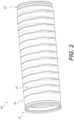
- FIG. 2 illustrates an exemplary corrugated pipe having an outer wrap according to some embodiments of the present disclosure.
- Wrapped pipe 200 may include integrated bell 210, similar to corrugated pipe 100. While not depicted, various bell designs may be used, such as a proud bell, for example.
- a proud bell may have an outer diameter that is larger than the outer diameter of the corrugated pipe body.
- Proud bells have an advantage over integrated bells in that they may be joined to a pipe end having a cross section matching that of the corrugated pipe body, rather than a specific spigot end. Therefore, the proud bell may connect to pipe cut to any length.
- integrated bells may be preferable to proud bells in underground applications, because integrated bells lie on grade in a trench.
- proud bells may require the digging of "bell holes" to excavate additional space in the trench to accommodate the larger outer diameter of the proud bell.
- wrapped pipe 200 may include spigot 220 to connect to bells of other pipes.
- Wrapped pipe uses corrugated pipe 100 with outer wrap 230 applied.
- outer wrap 230 may form a spiral pattern.
- Outer wrap 230 is applied as a helix (e.g., helical wrap 232) around corrugated pipe 100.
- Outer wrap 230 may be formed using fibers and plastic.
- fibers e.g., fiberglass or carbon fibers
- Polymers such as high density polyethylene (HDPE), polypropylene (PP), or polyvinyl chloride (PVC) may be used as the plastic.
- HDPE high density polyethylene
- PP polypropylene
- PVC polyvinyl chloride
- Other fibers or plastics may be used consistent with this disclosure.
- wrapped pipe may have a pipe and wrap of different materials.
- a pipe may be made of HDPE and a wrap may be made of fiber reinforced HDPE. This combination of materials may result in an increased strength to weight ratio because the product may be manufactured such that higher quality materials may be located more efficiently within the product.
- the corrugations may be made of a cheaper material.
- Higher quality materials may be used for the outer wrap and/or the liner.
- Higher quality materials may have a higher elastic and flexural modulus, better resistance to stress cracking, impact performance, and abrasion resistance, for example.
- the corrugations may be manufactured using a material with additives that reduce cost at the relative expense of structural integrity.
- outer wrap 230 may use continuous strand fiber.
- the fibers may run from a reel, embedding unbroken strands in a helix that wraps the pipe.
- spools of fiberglass thread may provide uninterrupted strands of fiberglass for embedding in plastic around a pipe.
- Continuous strand fiber may result in wrapped pipe with greater resilience than other wrap types.
- outer wrap 230 may use non-continuous fiber.
- Pelletized or short segments of fiber may be embedded in plastic.
- short fiber strands of 0.25 to 1 inch in length may be used.
- the fiber strands may align semi-oriented to the flow path as they are embedded in plastic.
- the fibers may be oriented linear to the flow path (e.g., circumferentially to the pipe) with minor deviations in the fiber orientation.
- semi-oriented may mean that more fibers would align parallel to the flow path than perpendicular to the flow path.
- semi-oriented fiber may lay, on average, at an angle less than 45 degrees from the direction of the flow path.
- the molten plastic may be pulled at a rate higher than the extruder flow rate to further orient the fiber stands in the direction of the flow.
- the fiber orientation may vary based on the type of fiber used, the length of the fibers, the diameter of the pipe to be wrapped, the type of plastic that the fibers are to be embedded in, and the thickness of the outer wrap.
- outer wrap 230 may use fiberglass impregnation. Pelletized or short segments of fiber may be embedded in plastic with no deliberate orientation, which may result in an isotropic material, which may have uniform structural integrity in all directions. By reducing the flow rate of the material through the die and/or reducing pulling (e.g., stretching) of the material as it exits the die, manufacturers may reduce the orientation of fiber strands in the outer wrap.
- outer wrap 230 may not use fibers.
- Plastic may be applied to corrugated pipe 100 by itself.
- HDPE may be wrapped onto a pipe in a helix to create a smooth outer layer.
- the temperature and flow rate of the plastic may be dependent upon the thickness of the wrap, the diameter of the pipe, and the type of material used in the plastic wrap without fiber.
- Example flow rates may range from 10 to 30 feet per minute.
- Outer wrap 230 may run the length of the pipe. When coupling mechanisms at the ends of the pipe require specific materials, outer wrap 230 may span the length of the corrugations, ending just before coupling mechanisms, such as bell 210 or spigot 220, for example. Further, pipes may be wrapped in portions or segments as a particular application may require.
- wrap 230 may wrap bell 210 completely and end at spigot 220.
- bell 210 may be completely covered.
- both bell 210 and spigot 220 may not be wrapped.
- a mechanism may be used to remove the wrap from spigot 220 and/or bell 210 as desired, regardless of the bell type.
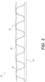
- FIG. 3 illustrates a cross-sectional view of an exemplary corrugated pipe having an outer wrap according to some embodiments of the present disclosure.
- Pipe profile 300 may include liner 340 and corrugation layer 320. These two layers may form a dual wall pipe.
- liner 340 may not be used, and corrugation layer 320 may form a single wall pipe that is wrapped.
- the outer wrap may form third wall 330.
- third wall 330 may be a layer of fibers embedded in plastic.
- the wrap may be applied in a helix, producing third wall edge 332 that may be generated from the overlap of the helix.
- the corrugated pipe may be rotated as the wrap is applied down the length of the pipe. This process may apply the outer wrap as a spiral. To ensure adequate coverage by the wrap, each spiral may slightly overlap, producing third wall edge 332.
- the wrap material may bond with the pipe material.
- the outer wrap and corrugation materials may be welded together by heating the materials to their thermoplastic state and pressing them together. Some materials used for the outer wrap and the corrugations may allow the use of solvent cements or epoxies to bond the wrap to the corrugations.
- the wrap material may be secured to the pipe by the tension of the wrap.
- Certain wrap and corrugation materials may not bond well together.
- a friction fit may secure the wrap to the corrugated pipe. The frictional forces may be strong enough such that the materials may appear to be attached.
- the wrap may separate from the pipe with less force than when the wrap is welded to the pipe.
- an outer wrap may be applied using a manufacturing process in accordance with some embodiments of the present disclosure.
- the steps discussed below and their order are merely exemplary. Steps may be performed in other orders. Further, certain steps may be omitted or duplicated consistent with this disclosure.
- a pipe may be formed in a corrugator.
- a dual wall pipe may be formed.
- An exemplary pipe having an inner liner layer with a second corrugated layer is produced using known processes.
- a single wall pipe with only a corrugated layer may be produced.
- pipe may be formed using a mandrel, such as ribbed pipe.
- Other embodiments may utilize pipe having any profile.
- the pipe may be cut to length.
- the corrugated pipe may be cut to its final length or a usable length so that the pipe may be transferred to the outer wrap die.
- the outer wrap may be applied in-line.
- the uncut corrugated pipe may continue directly to the outer wrap die assembly.
- the die assembly may apply the outer wrap in the pipe production line.
- the die may rotate around the stationary pipe after it exits the corrugator to apply the outer wrap.
- Control equipment may determine a wrap type.
- a computer controller may control the flow and application of the outer wrap extrusion die.
- the die may apply oriented continuous strand fiber, semi-oriented non-continuous fiber, fiberglass impregnation, or no fiber with the plastic.
- the die may allow the wrap type to be changed.
- the die assembly may wrap the pipe.
- a corrugated pipe may be placed adjacent to a filament die.
- the pipe may be rotated as it moves past the openings of the filament die.
- the rotation and traversal of the pipe in relation to the die assembly may be controlled so that the ribbon extruded from the die assembly forms a continuous outer layer.
- the pressure, temperature, and type of materials used in the extrusion process may be altered based on the wrap type.
- the temperature or flow rate may alter the wrap.
- temperatures ranging from 350 to 450 degrees Fahrenheit may be used to heat the wrap material for extrusion.
- the die may extrude plastic at a width ranging from 4 to 20 inches.
- the pitch of the helix may be determined based on the outer circumference of the pipe and the width of the extruded plastic.
- the die may also switch from continuous to non-continuous fiber. The switching process may be substantially automated by use of mechanical automation tools to change the sources of materials or die settings.
- Control equipment may also determine the thickness of the wrap layer.
- the control equipment may facilitate a particular flow rate of wrap material (e.g., the flow rate(s) plastic and/or fiber).
- Control equipment may also provide a particular wrap thickness by controlling the feed rate pulling the extruded material.
- manufacturing equipment may pull extruded outer wrap (e.g., plastic or plastic with fibers) twice as fast as the material is extruded.
- the ratio of the pull rate to the extrusion flow rate is greater than 1:1, the outer wrap material may stretch as it is applied to the pipe.
- Various pull to feed ratios may be used to control the thickness of the outer wrap.
- a higher pull to feed ratio may result in increased alignment of the fiber strands, when they are embedded in the plastic of the wrap.
- pulling the outer wrap material may have greater limitations.
- lower pull to feed ratios may need to be used.
- a corrugated HDPE pipe may be wrapped by heating fiber reinforced HDPE to a temperature of 350 to 450 degrees Fahrenheit for extruding at a rate of 20 feet per minute (e.g., plus or minus 5 feet per minute).
- the wrap material may be pulled at a ratio of 5:4, for example, relative to the extrusion rate.
- the pipe may have an inconsistent outer diameter, such as pipes with proud bells, for example, the rotational velocity of the pipe may vary to provide a consistent linear velocity at the outer diameter.
- the wrapped pipe may be held for cooling. Additional post-wrap processes may include removal of any wrap material over the spigot and/or the bell. For example, the exterior surface of the spigot may need to remain unwrapped to properly connect with other pipes.
- a mechanism may cut the wrap covering the spigot and remove the wrap, exposing the exterior surface of the spigot.
- the wrap process may not wrap the spigot, which may eliminate the need for a removal step.
Landscapes
- Engineering & Computer Science (AREA)
- Mechanical Engineering (AREA)
- General Engineering & Computer Science (AREA)
- Manufacturing & Machinery (AREA)
- Chemical & Material Sciences (AREA)
- Ceramic Engineering (AREA)
- Dispersion Chemistry (AREA)
- Rigid Pipes And Flexible Pipes (AREA)
- Details Of Indoor Wiring (AREA)
- Extrusion Moulding Of Plastics Or The Like (AREA)
Description
- This disclosure relates generally to pipe, and more particularly to pipe with an outer wrap, including systems and methods for making the same.
- Corrugated pipe is commonly used for drainage of soil and transportation of surface water. The corrugations typically create a pipe profile with steep sides and deep valleys. Given that these pipes are typically constructed using plastic, the corrugations may provide necessary structural integrity for the pipe by providing needed radial stiffness.
GB 550 448 A WO 2005/063465 A1 ,US 2004/099324 A1 ,US 2007/062595 A1 ,US 2008/210327 A1 ,US 2010/224306 A1 ,GB 2 424 935 A WO 94/28694 A1 US 5 089 074 A relate to pipes or hoses of the prior art. In particularWO 2005/063465 A1 discloses a plastic pipe comprising at least one connecting point for connection to another plastic pipe or to another connecting piece, wherein the connecting point has a sealing area. A reinforcement is applied to the connecting point in the sealing area and substantially or completely prevents the plastic of the connecting point from creeping in the sealing area. - However, the valleys of the corrugated pipe may also require inconvenient construction accommodations. For example, corrugated pipe may require additional work to backfill. Filling material may not readily conform to the corrugated exterior, requiring additional work to fill the valleys of the exterior wall. Triple wall corrugated pipe may include an outer layer of plastic, which may produce a less capricious outer surface. However, triple wall pipe suffers from increased cost, weight, and thickness. For example, the outer layer of a triple wall pipe may require additional material, adding significant production material costs and resulting in a heavier pipe.
- It is thus apparent that the need exists for a corrugated pipe having an outer wall or layer that may be lighter in weight, stronger, cheaper to produce, more efficient to construct, and exhibit a narrower width and a lower profile.
- The invention is defined by the claims.
- It is to be understood that both the foregoing general description and the following detailed description are exemplary and explanatory only and are not restrictive of the invention, as claimed.
- The accompanying drawings, which are incorporated in and constitute a part of this disclosure, illustrate exemplary embodiments and, together with the description, serve to explain the disclosed principles.
-
FIG. 1 illustrates an exemplary corrugated pipe according to some embodiments of the present disclosure. -
FIG. 2 illustrates an exemplary corrugated pipe having an outer wrap according to some embodiments of the present disclosure. -
FIG. 3 illustrates a cross-sectional view of an exemplary corrugated pipe having an outer wrap according to some embodiments of the present disclosure. - Exemplary embodiments are described with reference to the accompanying drawings. In the figures, the left-most digit(s) of a reference number identifies the figure in which the reference number first appears. Wherever convenient, the same reference numbers are used throughout the drawings to refer to the same or like parts. While examples and features of disclosed principles are described herein, modifications, adaptations, and other implementations are possible without departing from the scope of the disclosed embodiments. It is intended that the following detailed description be considered as exemplary only, with the true scope and spirit being indicated by the following claims.
- While standard corrugated pipe often suffers from increased jobsite backfill work, the pipe could be covered by a material to produce a smooth, but strong, exterior wall. For example, wrapping standard corrugated pipe in a material may result in an exterior wall without valleys which may eliminate gaps in the soil when placed in the ground at a jobsite, solving backfill problems. The outer wrap of the present invention may solve the backfill problems associated with dual wall corrugated pipe while not adding significant thickness to the pipe wall. The outer wrap material may also increase the strength of the pipe.
- An outer wrap may also allow additional pipe configurations because the wrap may consist of different materials than the pipe. For example, selected wrap material may allow manufacturers to reduce costs, while increasing strength, even though the particular wrap material may result in a heavier pipe. Other wrap materials may increase the strength to weight ratio of the pipe. Additional properties of alternative wrap materials may allow manufacturers to more effectively design wrapped pipe solutions to meet design constraints.
- Illustrative embodiments of the present disclosure are listed below. In one embodiment, an exemplary corrugated pipe with an outer wrap is disclosed. In another embodiment, an exemplary process for making corrugated pipe with an outer wrap is disclosed. The products and processes disclosed may be used in combination or separately. For example, the disclosed process may be used to make additional products. Further, disclosed products may be manufactured using additional processes.
-
FIG. 1 illustrates an exemplary corrugated pipe according to some embodiments of the present disclosure.Corrugated pipe 100 may be conventional single wall pipe or dual wall pipe that is well known in the art. Additional types of pipe may serve ascorrugated pipe 100 consistent with this disclosure. -
Corrugated pipe 100 may include a corrugated outer wall. For example,corrugated pipe 100 may include a series ofcorrugations 120.Corrugations 120 may run the length ofcorrugated pipe 100. In an embodiment,corrugations 120 may form spiral corrugations or annular corrugations. For example,corrugations 120 could spiral in the longitudinal around the circumference of the pipe.Corrugated pipe 100 may connect to other pipes. In an embodiment,corrugated pipe 100 may includebell 110 to facilitate connections to other pipes. For example,bell 110 may surround and contain a spigot end of another pipe. The spigot may have a smaller outer diameter than the bell, so that the spigot may fit intobell 110. Other connection types may be used withcorrugated pipe 100. For example, a coupler may be used to connect to other pipes. - In an embodiment,
corrugated pipe 100 may have an inner wall. For example, corrugated pipe may be a dual wall pipe. A smooth inner wall surface may be necessary or desirable for certain applications. Accordingly, a dual wall pipe, which includes a smooth inner wall may be used to satisfy design constraints. For example, a smooth inner wall may be necessary to meet pipe strength requirements or to satisfy flow path specifications. When specifications require a consistent pipe inner diameter, plans may rely on dual wall pipe having an inner wall. In other embodiments, corrugated pipe may be a single wall pipe. -
Corrugated pipe 100 may be made of plastic. In an embodiment, the material ofcorrugated pipe 100 may include plastic or thermoplastic polymers. For example, corrugated pipe may be made of high density polyethylene (HDPE) or polypropylene (PP).Corrugated pipe 100 may alternatively comprise a variety of other materials including, for example, other plastics, metals, or composite materials. - While
FIG. 1 describescorrugated pipe 100, other pipe types may be used consistent with this disclosure. In an embodiment, ribbed pipe may be wrapped. In other embodiments, pipes having any profile may be wrapped. -
FIG. 2 illustrates an exemplary corrugated pipe having an outer wrap according to some embodiments of the present disclosure. Wrappedpipe 200 may includeintegrated bell 210, similar tocorrugated pipe 100. While not depicted, various bell designs may be used, such as a proud bell, for example. A proud bell may have an outer diameter that is larger than the outer diameter of the corrugated pipe body. Proud bells have an advantage over integrated bells in that they may be joined to a pipe end having a cross section matching that of the corrugated pipe body, rather than a specific spigot end. Therefore, the proud bell may connect to pipe cut to any length. However, integrated bells may be preferable to proud bells in underground applications, because integrated bells lie on grade in a trench. Conversely, proud bells may require the digging of "bell holes" to excavate additional space in the trench to accommodate the larger outer diameter of the proud bell. As illustrated, wrappedpipe 200 may includespigot 220 to connect to bells of other pipes. - Wrapped pipe uses
corrugated pipe 100 withouter wrap 230 applied. In an embodiment of the present disclosure,outer wrap 230 may form a spiral pattern.Outer wrap 230 is applied as a helix (e.g., helical wrap 232) aroundcorrugated pipe 100. -
Outer wrap 230 may be formed using fibers and plastic. In an embodiment, fibers (e.g., fiberglass or carbon fibers) may be embedded in plastic. Polymers such as high density polyethylene (HDPE), polypropylene (PP), or polyvinyl chloride (PVC) may be used as the plastic. Other fibers or plastics may be used consistent with this disclosure. - In an embodiment, wrapped pipe may have a pipe and wrap of different materials. For example, a pipe may be made of HDPE and a wrap may be made of fiber reinforced HDPE. This combination of materials may result in an increased strength to weight ratio because the product may be manufactured such that higher quality materials may be located more efficiently within the product.
- In another example wrapped pipe, the corrugations may be made of a cheaper material. Higher quality materials may be used for the outer wrap and/or the liner. Higher quality materials may have a higher elastic and flexural modulus, better resistance to stress cracking, impact performance, and abrasion resistance, for example. When corrugations are made from a different material than the liner and/or the outer wrap, the corrugations may be manufactured using a material with additives that reduce cost at the relative expense of structural integrity.
- In another embodiment,
outer wrap 230 may use continuous strand fiber. The fibers may run from a reel, embedding unbroken strands in a helix that wraps the pipe. For example, spools of fiberglass thread may provide uninterrupted strands of fiberglass for embedding in plastic around a pipe. Continuous strand fiber may result in wrapped pipe with greater resilience than other wrap types. - In an embodiment,
outer wrap 230 may use non-continuous fiber. Pelletized or short segments of fiber may be embedded in plastic. For example, short fiber strands of 0.25 to 1 inch in length may be used. By configuring the feed of the molten plastic as the fiber strands are embedded in plastic, the fiber strands may align semi-oriented to the flow path as they are embedded in plastic. For example, the fibers may be oriented linear to the flow path (e.g., circumferentially to the pipe) with minor deviations in the fiber orientation. In an embodiment, semi-oriented may mean that more fibers would align parallel to the flow path than perpendicular to the flow path. For example, semi-oriented fiber may lay, on average, at an angle less than 45 degrees from the direction of the flow path. - In an embodiment, the molten plastic may be pulled at a rate higher than the extruder flow rate to further orient the fiber stands in the direction of the flow. The fiber orientation may vary based on the type of fiber used, the length of the fibers, the diameter of the pipe to be wrapped, the type of plastic that the fibers are to be embedded in, and the thickness of the outer wrap.
- In an embodiment,
outer wrap 230 may use fiberglass impregnation. Pelletized or short segments of fiber may be embedded in plastic with no deliberate orientation, which may result in an isotropic material, which may have uniform structural integrity in all directions. By reducing the flow rate of the material through the die and/or reducing pulling (e.g., stretching) of the material as it exits the die, manufacturers may reduce the orientation of fiber strands in the outer wrap. - In another embodiment,
outer wrap 230 may not use fibers. Plastic may be applied tocorrugated pipe 100 by itself. For example, HDPE may be wrapped onto a pipe in a helix to create a smooth outer layer. The temperature and flow rate of the plastic may be dependent upon the thickness of the wrap, the diameter of the pipe, and the type of material used in the plastic wrap without fiber. Example flow rates may range from 10 to 30 feet per minute. -
Outer wrap 230 may run the length of the pipe. When coupling mechanisms at the ends of the pipe require specific materials,outer wrap 230 may span the length of the corrugations, ending just before coupling mechanisms, such asbell 210 orspigot 220, for example. Further, pipes may be wrapped in portions or segments as a particular application may require. - In an embodiment, wrap 230 may wrap
bell 210 completely and end atspigot 220. For example,bell 210 may be completely covered. In another embodiment, bothbell 210 andspigot 220 may not be wrapped. When a continuous wrap process is used, a mechanism may be used to remove the wrap fromspigot 220 and/orbell 210 as desired, regardless of the bell type. -
FIG. 3 illustrates a cross-sectional view of an exemplary corrugated pipe having an outer wrap according to some embodiments of the present disclosure.Pipe profile 300 may includeliner 340 andcorrugation layer 320. These two layers may form a dual wall pipe. In some embodiments,liner 340 may not be used, andcorrugation layer 320 may form a single wall pipe that is wrapped. The outer wrap may formthird wall 330. For example,third wall 330 may be a layer of fibers embedded in plastic. - In an embodiment, the wrap may be applied in a helix, producing
third wall edge 332 that may be generated from the overlap of the helix. For example, the corrugated pipe may be rotated as the wrap is applied down the length of the pipe. This process may apply the outer wrap as a spiral. To ensure adequate coverage by the wrap, each spiral may slightly overlap, producingthird wall edge 332. - In an embodiment, the wrap material may bond with the pipe material. For example, the outer wrap and corrugation materials may be welded together by heating the materials to their thermoplastic state and pressing them together. Some materials used for the outer wrap and the corrugations may allow the use of solvent cements or epoxies to bond the wrap to the corrugations.
- In an embodiment, the wrap material may be secured to the pipe by the tension of the wrap. Certain wrap and corrugation materials may not bond well together. For example, when dissimilar materials are used, such as an outer wrap made of PP and a corrugated pipe made of HDPE, a friction fit may secure the wrap to the corrugated pipe. The frictional forces may be strong enough such that the materials may appear to be attached. However, the wrap may separate from the pipe with less force than when the wrap is welded to the pipe.
- In some embodiments, an outer wrap may be applied using a manufacturing process in accordance with some embodiments of the present disclosure. The steps discussed below and their order are merely exemplary. Steps may be performed in other orders. Further, certain steps may be omitted or duplicated consistent with this disclosure.
- In an embodiment, a pipe may be formed in a corrugator. For example, a dual wall pipe may be formed. An exemplary pipe having an inner liner layer with a second corrugated layer is produced using known processes. In an embodiment, a single wall pipe with only a corrugated layer may be produced. In an embodiment, pipe may be formed using a mandrel, such as ribbed pipe. Other embodiments may utilize pipe having any profile.
- After the pipe is formed, the pipe may be cut to length. For example, the corrugated pipe may be cut to its final length or a usable length so that the pipe may be transferred to the outer wrap die.
- In an embodiment, instead of the pipe being cut to length, the outer wrap may be applied in-line. For example, the uncut corrugated pipe may continue directly to the outer wrap die assembly. The die assembly may apply the outer wrap in the pipe production line. The die may rotate around the stationary pipe after it exits the corrugator to apply the outer wrap.
- Control equipment may determine a wrap type. In an embodiment, a computer controller may control the flow and application of the outer wrap extrusion die. For example, the die may apply oriented continuous strand fiber, semi-oriented non-continuous fiber, fiberglass impregnation, or no fiber with the plastic. The die may allow the wrap type to be changed.
- The die assembly may wrap the pipe. In an embodiment, a corrugated pipe may be placed adjacent to a filament die. The pipe may be rotated as it moves past the openings of the filament die. The rotation and traversal of the pipe in relation to the die assembly may be controlled so that the ribbon extruded from the die assembly forms a continuous outer layer.
- In an embodiment, the pressure, temperature, and type of materials used in the extrusion process may be altered based on the wrap type. For example, the temperature or flow rate may alter the wrap. For example, for HDPE temperatures ranging from 350 to 450 degrees Fahrenheit may be used to heat the wrap material for extrusion. The die may extrude plastic at a width ranging from 4 to 20 inches. When the wrap is applied as a helix, the pitch of the helix may be determined based on the outer circumference of the pipe and the width of the extruded plastic. The die may also switch from continuous to non-continuous fiber. The switching process may be substantially automated by use of mechanical automation tools to change the sources of materials or die settings.
- Control equipment may also determine the thickness of the wrap layer. The control equipment may facilitate a particular flow rate of wrap material (e.g., the flow rate(s) plastic and/or fiber). Control equipment may also provide a particular wrap thickness by controlling the feed rate pulling the extruded material. For example, manufacturing equipment may pull extruded outer wrap (e.g., plastic or plastic with fibers) twice as fast as the material is extruded. When the ratio of the pull rate to the extrusion flow rate is greater than 1:1, the outer wrap material may stretch as it is applied to the pipe. Various pull to feed ratios may be used to control the thickness of the outer wrap. Moreover, a higher pull to feed ratio (e.g., increased pulling of the outer wrap) may result in increased alignment of the fiber strands, when they are embedded in the plastic of the wrap. When using continuous strand fiber, pulling the outer wrap material may have greater limitations. For example, lower pull to feed ratios may need to be used. In an example wrapped pipe, a corrugated HDPE pipe may be wrapped by heating fiber reinforced HDPE to a temperature of 350 to 450 degrees Fahrenheit for extruding at a rate of 20 feet per minute (e.g., plus or minus 5 feet per minute). The wrap material may be pulled at a ratio of 5:4, for example, relative to the extrusion rate. When the pipe may have an inconsistent outer diameter, such as pipes with proud bells, for example, the rotational velocity of the pipe may vary to provide a consistent linear velocity at the outer diameter.
- After wrapping is complete, the wrapped pipe may be held for cooling. Additional post-wrap processes may include removal of any wrap material over the spigot and/or the bell. For example, the exterior surface of the spigot may need to remain unwrapped to properly connect with other pipes. In order to remove the wrapping, should the wrapping process cover the spigot, a mechanism may cut the wrap covering the spigot and remove the wrap, exposing the exterior surface of the spigot. In some embodiments, the wrap process may not wrap the spigot, which may eliminate the need for a removal step.
- The specification has described pipe with an outer wrap. The illustrated steps are set out to explain the exemplary embodiments shown, and it should be anticipated that ongoing technological development will change the manner in which particular functions are performed. These examples are presented herein for purposes of illustration, and not limitation. Further, the boundaries of the functional building blocks have been arbitrarily defined herein for the convenience of the description. Alternative boundaries can be defined so long as the specified functions and relationships thereof are appropriately performed. Alternatives (including equivalents, extensions, variations, deviations, etc., of those described herein) will be apparent to persons skilled in the relevant art(s) based on the teachings contained herein. Such alternatives fall within the scope and spirit of the disclosed embodiments. Also, the words "comprising," "having," "containing," and "including," and other similar forms are intended to be equivalent in meaning and be open ended in that an item or items following any one of these words is not meant to be an exhaustive listing of such item or items, or meant to be limited to only the listed item or items. It must also be noted that as used herein and in the appended claims, the singular forms "a," "an," and "the" include plural references unless the context clearly dictates otherwise.
- It is intended that the disclosure and examples be considered as exemplary only, whereas the invention is defined by the following claims.
Claims (13)
- A pipe (200) for drainage of soil and transportation of surface water comprising:an axially extended bore defined by a corrugated outer wall, wherein the corrugated outer wall comprises plastic; andan outer wrap (230) applied to the outer wall, wherein:
the outer wrap (230) comprises plastic, andthe outer wrap (230) is applied in an overlapping helical pattern (232) completely covering the corrugated outer wall. - The pipe (200) of claim 1, wherein the plastic of the bore and the plastic of the outer wrap (230) are different types of plastic.
- The pipe (200) of claim 1, wherein the plastic of the outer wall and the plastic of the outer wrap (230) are welded together.
- The pipe (200) of claim 1, wherein the axially extended bore is made of high density polyethylene (HDPE) or polypropylene (PP).
- The pipe (200) of claim 1, wherein the outer wrap (230) is made of high density polyethylene (HDPE) or polypropylene (PP) or polyvinyl chloride (PVC).
- A method of preparing the pipe (200) according to claim 1, wherein an outer wrap (230) is applied to a corrugated pipe (100), the method comprising:cutting a corrugated pipe (100) to a final length or a usable length;determining a wrap type to be applied to the corrugated pipe (100);determining a flow rate for applying a wrap of the wrap type based on a type of plastic used in the wrap, a type of fiber used in the wrap, and the wrap type;applying a wrap made of the type of fiber and the type of plastic to the corrugated pipe (100) using the determined flow rate producing a smooth outer surface.
- A method of preparing a pipe (200) according to claim 1, wherein an outer wrap (230) is applied to a corrugated pipe (100), the method comprising:extruding an uncut corrugated pipe (100) from a pipe extrusion device;determining a wrap type to apply to the uncut corrugated pipe (100);determining a flow rate for applying a wrap of the wrap type based on a type of plastic used in the wrap, a type of fiber used in the wrap, and the wrap type;applying a wrap made of the type of fiber and the type of plastic to the corrugated pipe (100) using the determined flow rate producing a smooth outer surface.
- The method of claim 6 or 7, wherein the type of fiber comprises continuous strand fiber.
- The method of claim 6 or 7, wherein the type of fiber comprises short strands of fiber.
- The method of claim 6 or 7, wherein the wrap type may include one or more of: oriented continuous strand fiber, semi-oriented non-continuous fiber, fiberglass impregnation, or no fiber.
- The method of claim 6, wherein applying the wrap includes controlling the thickness of the outer wrap by varying the ratio of pull rate to extrusion flow rate.
- The method of claim 7, wherein applying the wrap comprises:
applying the wrap from a rotating wrap extrusion device that circumscribes an outer surface of the uncut corrugated pipe (100) with the wrap. - The method of claim 6 or 7, further comprising:heating the type of plastic used in the wrap to a predetermined temperature; andextruding the type of plastic at the determined flow rate, wherein the flow rate ranges from 0.0762 to 0.127 metres per second.
Applications Claiming Priority (3)
| Application Number | Priority Date | Filing Date | Title |
|---|---|---|---|
| US14/732,146 US9759354B2 (en) | 2015-06-05 | 2015-06-05 | Pipe with an outer wrap |
| EP16729455.2A EP3303896B1 (en) | 2015-06-05 | 2016-06-02 | Pipe with an outer wrap |
| PCT/US2016/035498 WO2016196780A1 (en) | 2015-06-05 | 2016-06-02 | Pipe with an outer wrap |
Related Parent Applications (1)
| Application Number | Title | Priority Date | Filing Date |
|---|---|---|---|
| EP16729455.2A Division EP3303896B1 (en) | 2015-06-05 | 2016-06-02 | Pipe with an outer wrap |
Publications (3)
| Publication Number | Publication Date |
|---|---|
| EP3809032A1 EP3809032A1 (en) | 2021-04-21 |
| EP3809032C0 EP3809032C0 (en) | 2025-01-22 |
| EP3809032B1 true EP3809032B1 (en) | 2025-01-22 |
Family
ID=56131648
Family Applications (2)
| Application Number | Title | Priority Date | Filing Date |
|---|---|---|---|
| EP16729455.2A Active EP3303896B1 (en) | 2015-06-05 | 2016-06-02 | Pipe with an outer wrap |
| EP20213943.2A Active EP3809032B1 (en) | 2015-06-05 | 2016-06-02 | Pipe with an outer wrap |
Family Applications Before (1)
| Application Number | Title | Priority Date | Filing Date |
|---|---|---|---|
| EP16729455.2A Active EP3303896B1 (en) | 2015-06-05 | 2016-06-02 | Pipe with an outer wrap |
Country Status (12)
| Country | Link |
|---|---|
| US (7) | US9759354B2 (en) |
| EP (2) | EP3303896B1 (en) |
| BR (1) | BR112017025721B1 (en) |
| CA (2) | CA3192935A1 (en) |
| CL (1) | CL2017003064A1 (en) |
| CO (1) | CO2017012983A2 (en) |
| DK (1) | DK3303896T3 (en) |
| ES (2) | ES3012107T3 (en) |
| MX (2) | MX2017015695A (en) |
| PE (2) | PE20221268A1 (en) |
| PL (2) | PL3809032T3 (en) |
| WO (1) | WO2016196780A1 (en) |
Families Citing this family (11)
| Publication number | Priority date | Publication date | Assignee | Title |
|---|---|---|---|---|
| US20150136255A1 (en) * | 2013-11-19 | 2015-05-21 | Advanced Drainage Systems, Inc. | Pipe having slits |
| US10077856B2 (en) * | 2015-06-05 | 2018-09-18 | Advanced Drainage Systems Inc. | Pipe with an outer wrap |
| US9759354B2 (en) | 2015-06-05 | 2017-09-12 | Advanced Drainage Systems, Inc. | Pipe with an outer wrap |
| US10077857B2 (en) * | 2015-06-05 | 2018-09-18 | Advanced Drainage Systems Inc. | Pipe with an outer wrap |
| CN107654747B (en) * | 2017-09-05 | 2023-08-25 | 河南金铨塑业有限公司 | High-strength cracking-resistant plastic composite pipe |
| US10968588B2 (en) | 2018-01-10 | 2021-04-06 | Keller North America, Inc. | Method and apparatus for field fabrication of socked perforated drains |
| CN110744800B (en) * | 2019-10-31 | 2021-05-25 | 重庆市一龙管道有限公司 | Steel strip spiral corrugated pipe production mold and corrugated pipe production method |
| CN111895190A (en) * | 2020-08-13 | 2020-11-06 | 青岛永科机械科技有限公司 | Plastic thermal-state winding structure wall pipe |
| CN112856057B (en) * | 2021-01-19 | 2022-11-01 | 上海英泰塑胶股份有限公司 | Continuous fiber glass fiber board stirrup pipe composite arc top triangular corrugated pipeline |
| EP4587251B1 (en) | 2023-09-25 | 2026-04-08 | Advanced Drainage Systems, Inc. | Dual pipe manufacturing cell |
| WO2025072185A1 (en) | 2023-09-25 | 2025-04-03 | Advanced Drainage Systems, Inc. | Dual pipe manufacturing cell |
Citations (1)
| Publication number | Priority date | Publication date | Assignee | Title |
|---|---|---|---|---|
| US5089074A (en) * | 1989-09-11 | 1992-02-18 | Dayco Products, Inc. | Flexible hose construction and method of making the same |
Family Cites Families (59)
| Publication number | Priority date | Publication date | Assignee | Title |
|---|---|---|---|---|
| GB550448A (en) | 1941-06-06 | 1943-01-08 | Bernard Wilkinson | Improvements in and relating to self-sealing petrol pipes |
| US2888954A (en) * | 1955-09-09 | 1959-06-02 | Gates Mitten Howell | Laminated plastic pipe |
| NL134531C (en) * | 1966-05-02 | |||
| US3605232A (en) * | 1969-02-17 | 1971-09-20 | Vernon C Hines | Method of lining flexible metal l's |
| US3646610A (en) * | 1969-03-10 | 1972-02-29 | True Temper Corp | Fiber glass reinforced golf shaft |
| US4053269A (en) | 1973-03-14 | 1977-10-11 | Sidney Levy | Apparatus for forming a composite tape |
| US4076481A (en) * | 1975-01-15 | 1978-02-28 | Sussex Plastics Engineering, Inc. | Annular extrusion die |
| US4269234A (en) * | 1979-05-18 | 1981-05-26 | Tri State Culvert Corporation | High strength pipe |
| DE3603481A1 (en) * | 1986-02-05 | 1987-08-06 | Wilhelm Hegler | PLASTIC CORRUGATED TUBE WITH MOLDED CONNECTOR |
| KR890005304B1 (en) * | 1986-04-23 | 1989-12-20 | Shiro Kanao | Flexible hard pipe |
| US4751799A (en) | 1986-07-09 | 1988-06-21 | A-Lok Product, Inc. | Method and apparatus for lining manhole assemblies and the like |
| US5354521A (en) | 1992-02-05 | 1994-10-11 | Gas Research Institute | Method of making a magnetically detectable plastic pipe |
| US5381511A (en) | 1993-06-02 | 1995-01-10 | W. L. Gore & Associates, Inc. | Flexible electrically heatable hose |
| US5705351A (en) * | 1994-10-25 | 1998-01-06 | Sahasrabudhe; Madhao B. | Diagnosis of cancer using tumor-mimetic cell surface antigen from chemically modified normal cells |
| US5678610A (en) * | 1995-02-24 | 1997-10-21 | Oem/Miller Corporation | Composite tube and method of manufacture |
| US8678042B2 (en) | 1995-09-28 | 2014-03-25 | Fiberspar Corporation | Composite spoolable tube |
| USRE38508E1 (en) | 1997-06-28 | 2004-04-27 | Laminators Incorporated | Structural panels with metal faces and corrugated plastic core |
| US5911932A (en) | 1997-07-09 | 1999-06-15 | R. Charles Balmer | Method of prepregging with resin |
| US5914163A (en) * | 1997-10-10 | 1999-06-22 | General Motors Corporation | Reduced crush initiation force composite tube |
| FR2775049B1 (en) * | 1998-02-17 | 2000-03-31 | Westaflex Automobile | PIPE FOR TRANSPORTING GASEOUS FLUID, PARTICULARLY IN MOTOR VEHICLES, AND METHOD FOR MANUFACTURING THE SAME |
| JP2000046256A (en) | 1998-05-29 | 2000-02-18 | Takiron Co Ltd | Corrugated pipe and manufacture thereof |
| US6405974B1 (en) * | 1998-08-12 | 2002-06-18 | F. John Herrington | Ribbed core dual wall structure |
| US6629547B1 (en) * | 1998-10-09 | 2003-10-07 | Sekisui Chemical Co., Ltd. | Composite high-pressure pipe and method of joining same |
| US6399002B1 (en) * | 1998-11-23 | 2002-06-04 | Manfred A. A. Lupke | Method of making a pipe with coupling conforming to pipe diameter |
| DE60114096T2 (en) | 2000-07-17 | 2006-07-06 | Conception Et Development Michelin S.A. | Continuous impregnation of very long fibers with resin for the production of elongated composite elements |
| US6688339B2 (en) * | 2000-08-29 | 2004-02-10 | Sekisui Chemical Co., Ltd. | Composite high-pressure tube and method of manufacturing the tube |
| US7144625B2 (en) | 2000-09-06 | 2006-12-05 | George Tunis | Wire reinforced thermoplastic coating |
| JP4846103B2 (en) | 2001-02-07 | 2011-12-28 | 三菱レイヨン株式会社 | Fiber reinforced resin pipe and power transmission shaft using the same |
| ATE280351T1 (en) * | 2001-02-09 | 2004-11-15 | Ralph-Peter Dr-Ing Hegler | PIPE KIT |
| GB2391917B (en) | 2001-04-27 | 2005-10-26 | Fiberspar Corp | Improved composite tubing |
| DK200100832A (en) | 2001-05-23 | 2001-05-23 | Nkt Flexibles Is | Method of manufacturing a reinforcing element for a flexible pipeline |
| US6497956B1 (en) | 2001-09-07 | 2002-12-24 | Biolumber Inc. | Structural recycled plastic lumber |
| US20030090112A1 (en) * | 2001-11-14 | 2003-05-15 | Brad Baughman | Pipe joint assembly |
| US6899140B2 (en) | 2002-08-12 | 2005-05-31 | Wellstream International Limited | Flexible pipe and method of manufacturing same using metal reinforced tape |
| US6889715B2 (en) * | 2002-11-27 | 2005-05-10 | Wellstream International Limited | Flexible tubular member with sealed tape layer |
| US7093638B2 (en) | 2003-04-21 | 2006-08-22 | Lignum Vitae Limited | Apparatus and method for manufacture and use of composite fiber components |
| US7204286B2 (en) | 2003-12-15 | 2007-04-17 | Jamco Corporation | Apparatus for continuously forming FRP square pipe |
| DE20321240U1 (en) | 2003-12-22 | 2006-08-03 | Drossbach Gmbh & Co. Kg | Device for applying a reinforcement to a plastic pipe |
| JP2005308210A (en) * | 2004-03-26 | 2005-11-04 | Hitachi Metals Ltd | Flexible tube |
| US8733405B2 (en) | 2005-03-14 | 2014-05-27 | Advanced Drainage Systems, Inc. | Corrugated pipe with outer layer |
| US7484535B2 (en) * | 2005-03-14 | 2009-02-03 | Advanced Drainage Systems, Inc. | Corrugated pipe with outer layer |
| US7156128B1 (en) * | 2005-06-21 | 2007-01-02 | Kanaflex Corporation | Synthetic resin pipe |
| US7600537B2 (en) * | 2005-09-16 | 2009-10-13 | Honeywell International Inc. | Reinforced plastic pipe |
| US7987885B2 (en) | 2005-12-01 | 2011-08-02 | Saint-Gobain Performance Plastics Corporation | System and die for forming a continuous filament reinforced structural plastic profile by pultrusion/coextrusion |
| WO2007130553A2 (en) | 2006-05-02 | 2007-11-15 | Dow Global Technologies Inc. | High-density polyethylene compositions, method of making the same, wire and cable jackets made therefrom, and method of making such wire and cable jackets |
| DE102006025248A1 (en) | 2006-05-29 | 2007-12-06 | Beltec Industrietechnik Gmbh | Fiber reinforced plastic drilling anchor |
| GB0712586D0 (en) | 2007-06-28 | 2007-08-08 | Wellstream Int Ltd | Flexible pipe |
| US8820800B2 (en) * | 2007-11-16 | 2014-09-02 | Advanced Drainage Systems, Inc. | Multi-wall corrugated pipe couplings and methods |
| US8820801B2 (en) * | 2007-11-16 | 2014-09-02 | Advanced Drainage System, Inc. | Multi-wall corrugated pipe couplings and methods |
| US8579624B2 (en) | 2008-02-11 | 2013-11-12 | Advanced Drainage Systems, Inc. | Systems and methods for making multi-wall corrugated pipe |
| US8747098B1 (en) | 2008-03-24 | 2014-06-10 | Ebert Composites Corporation | Thermoplastic pultrusion die system and method |
| US7896160B2 (en) * | 2008-06-12 | 2011-03-01 | Carriff Engineered Fabrics Corporation | System for supplying tubular geotextile material for perforated drain pipes |
| EP2310192B1 (en) | 2008-06-13 | 2014-02-26 | Lockheed Martin Corporation | Process and apparatus for molding continuous-fiber composite articles |
| CN102300936B (en) | 2009-03-16 | 2014-03-12 | 东丽株式会社 | Fiber reinforced resin composition, molding material, and method for producing fiber reinforced resin composition |
| WO2011049668A2 (en) | 2009-10-20 | 2011-04-28 | Pipestream B.V. | Method and apparatus for reinforcing a pipeline |
| US8152949B2 (en) | 2009-11-20 | 2012-04-10 | Lockheed Martin Corporation | Pultruded arc-segmented pipe |
| BR112013028769A2 (en) * | 2011-05-10 | 2017-01-24 | Nat Oiwell Varco Denmark I S | non-stick flexible hose for underwater fluid transfer |
| US9759354B2 (en) * | 2015-06-05 | 2017-09-12 | Advanced Drainage Systems, Inc. | Pipe with an outer wrap |
| US10077857B2 (en) * | 2015-06-05 | 2018-09-18 | Advanced Drainage Systems Inc. | Pipe with an outer wrap |
-
2015
- 2015-06-05 US US14/732,146 patent/US9759354B2/en active Active
-
2016
- 2016-06-02 CA CA3192935A patent/CA3192935A1/en active Pending
- 2016-06-02 ES ES20213943T patent/ES3012107T3/en active Active
- 2016-06-02 PE PE2022000244A patent/PE20221268A1/en unknown
- 2016-06-02 PE PE2017002528A patent/PE20180471A1/en unknown
- 2016-06-02 EP EP16729455.2A patent/EP3303896B1/en active Active
- 2016-06-02 CA CA2988114A patent/CA2988114C/en active Active
- 2016-06-02 WO PCT/US2016/035498 patent/WO2016196780A1/en not_active Ceased
- 2016-06-02 PL PL20213943.2T patent/PL3809032T3/en unknown
- 2016-06-02 EP EP20213943.2A patent/EP3809032B1/en active Active
- 2016-06-02 DK DK16729455.2T patent/DK3303896T3/en active
- 2016-06-02 BR BR112017025721-1A patent/BR112017025721B1/en active IP Right Grant
- 2016-06-02 MX MX2017015695A patent/MX2017015695A/en unknown
- 2016-06-02 PL PL16729455T patent/PL3303896T3/en unknown
- 2016-06-02 ES ES16729455T patent/ES2858550T3/en active Active
-
2017
- 2017-05-15 US US15/594,859 patent/US10550963B2/en active Active
- 2017-12-01 CL CL2017003064A patent/CL2017003064A1/en unknown
- 2017-12-04 MX MX2021015886A patent/MX2021015886A/en unknown
- 2017-12-18 CO CONC2017/0012983A patent/CO2017012983A2/en unknown
-
2020
- 2020-01-22 US US16/749,543 patent/US10927981B2/en active Active
-
2021
- 2021-01-21 US US17/154,262 patent/US11555561B2/en active Active
-
2022
- 2022-12-23 US US18/145,959 patent/US11898688B2/en active Active
-
2024
- 2024-01-23 US US18/419,633 patent/US12259084B2/en active Active
-
2025
- 2025-02-21 US US19/059,894 patent/US20250189061A1/en active Pending
Patent Citations (1)
| Publication number | Priority date | Publication date | Assignee | Title |
|---|---|---|---|---|
| US5089074A (en) * | 1989-09-11 | 1992-02-18 | Dayco Products, Inc. | Flexible hose construction and method of making the same |
Also Published As
Similar Documents
| Publication | Publication Date | Title |
|---|---|---|
| US12259084B2 (en) | Pipe with an outer wrap | |
| US10077857B2 (en) | Pipe with an outer wrap | |
| US10077856B2 (en) | Pipe with an outer wrap | |
| EP2841835B1 (en) | Multilayer pipeline in a polymer material, device for manufacture of the multilayer pipeline and a method for manufacturing the multilayer pipeline | |
| US20120048455A1 (en) | Thermoplastic pipe made with commingled glass fibers | |
| JP6038719B2 (en) | Reinforcing band member and manufacturing method thereof | |
| CN102777710B (en) | Multilayer steel compound belt material winding water input pipe, preparation method and device of pipe and steel compound belt material | |
| EP2658701B1 (en) | Method of manufacturing a pipe from thermoplastic material | |
| EP2106897B1 (en) | Plastic pipe with profiled layer and method for manufacturing the same | |
| WO2001013022A1 (en) | A wiremesh reinforcement-plastic composite pipe component and method for making the same | |
| CN210240810U (en) | High-wear-resistance composite reinforced polyethylene structure wall winding pipe | |
| WO2016110509A1 (en) | Multi -channel hose for use as a heat exchanger and method for manufacturing a multi -channel hose | |
| KR100939346B1 (en) | Water barrier pipe and manufacturing device thereof | |
| RU2843297C1 (en) | Multilayer antistatic flexible polymer sleeve and method of production thereof | |
| JP5044744B2 (en) | Method for manufacturing flexible laminated hose | |
| JP5898467B2 (en) | Synthetic resin hose and its manufacturing method | |
| KR100459911B1 (en) | Fabricating method for flexible double pipe of high strength and controllable weight | |
| KR101181079B1 (en) | A Double-wall Pipe Made of Synthetic Resin Having Improved Hardness | |
| WO2024175995A1 (en) | Subsea umbilical composite tube and method of manufacture | |
| HK1208061B (en) | Multilayer pipeline in a polymer material, device for manufacture of the multilayer pipeline and a method for manufacturing the multilayer pipeline |
Legal Events
| Date | Code | Title | Description |
|---|---|---|---|
| PUAI | Public reference made under article 153(3) epc to a published international application that has entered the european phase |
Free format text: ORIGINAL CODE: 0009012 |
|
| STAA | Information on the status of an ep patent application or granted ep patent |
Free format text: STATUS: THE APPLICATION HAS BEEN PUBLISHED |
|
| AC | Divisional application: reference to earlier application |
Ref document number: 3303896 Country of ref document: EP Kind code of ref document: P |
|
| AK | Designated contracting states |
Kind code of ref document: A1 Designated state(s): AL AT BE BG CH CY CZ DE DK EE ES FI FR GB GR HR HU IE IS IT LI LT LU LV MC MK MT NL NO PL PT RO RS SE SI SK SM TR |
|
| STAA | Information on the status of an ep patent application or granted ep patent |
Free format text: STATUS: REQUEST FOR EXAMINATION WAS MADE |
|
| 17P | Request for examination filed |
Effective date: 20211021 |
|
| RBV | Designated contracting states (corrected) |
Designated state(s): AL AT BE BG CH CY CZ DE DK EE ES FI FR GB GR HR HU IE IS IT LI LT LU LV MC MK MT NL NO PL PT RO RS SE SI SK SM TR |
|
| STAA | Information on the status of an ep patent application or granted ep patent |
Free format text: STATUS: EXAMINATION IS IN PROGRESS |
|
| 17Q | First examination report despatched |
Effective date: 20221017 |
|
| P01 | Opt-out of the competence of the unified patent court (upc) registered |
Effective date: 20230516 |
|
| GRAP | Despatch of communication of intention to grant a patent |
Free format text: ORIGINAL CODE: EPIDOSNIGR1 |
|
| STAA | Information on the status of an ep patent application or granted ep patent |
Free format text: STATUS: GRANT OF PATENT IS INTENDED |
|
| RIC1 | Information provided on ipc code assigned before grant |
Ipc: B29D 23/00 20060101ALI20240326BHEP Ipc: B29C 63/10 20060101ALI20240326BHEP Ipc: B29C 48/07 20190101ALI20240326BHEP Ipc: B29C 48/285 20190101ALI20240326BHEP Ipc: B29C 48/151 20190101ALI20240326BHEP Ipc: B29C 48/00 20190101ALI20240326BHEP Ipc: B29C 48/03 20190101ALI20240326BHEP Ipc: F16L 11/115 20060101ALI20240326BHEP Ipc: B29K 309/08 20060101ALI20240326BHEP Ipc: F16L 9/06 20060101ALI20240326BHEP Ipc: F16L 58/10 20060101AFI20240326BHEP |
|
| INTG | Intention to grant announced |
Effective date: 20240425 |
|
| GRAJ | Information related to disapproval of communication of intention to grant by the applicant or resumption of examination proceedings by the epo deleted |
Free format text: ORIGINAL CODE: EPIDOSDIGR1 |
|
| STAA | Information on the status of an ep patent application or granted ep patent |
Free format text: STATUS: EXAMINATION IS IN PROGRESS |
|
| GRAP | Despatch of communication of intention to grant a patent |
Free format text: ORIGINAL CODE: EPIDOSNIGR1 |
|
| STAA | Information on the status of an ep patent application or granted ep patent |
Free format text: STATUS: GRANT OF PATENT IS INTENDED |
|
| INTC | Intention to grant announced (deleted) | ||
| INTG | Intention to grant announced |
Effective date: 20240909 |
|
| GRAS | Grant fee paid |
Free format text: ORIGINAL CODE: EPIDOSNIGR3 |
|
| GRAA | (expected) grant |
Free format text: ORIGINAL CODE: 0009210 |
|
| STAA | Information on the status of an ep patent application or granted ep patent |
Free format text: STATUS: THE PATENT HAS BEEN GRANTED |
|
| AC | Divisional application: reference to earlier application |
Ref document number: 3303896 Country of ref document: EP Kind code of ref document: P |
|
| AK | Designated contracting states |
Kind code of ref document: B1 Designated state(s): AL AT BE BG CH CY CZ DE DK EE ES FI FR GB GR HR HU IE IS IT LI LT LU LV MC MK MT NL NO PL PT RO RS SE SI SK SM TR |
|
| REG | Reference to a national code |
Ref country code: GB Ref legal event code: FG4D |
|
| REG | Reference to a national code |
Ref country code: CH Ref legal event code: EP |
|
| REG | Reference to a national code |
Ref country code: IE Ref legal event code: FG4D |
|
| REG | Reference to a national code |
Ref country code: DE Ref legal event code: R096 Ref document number: 602016091058 Country of ref document: DE |
|
| U01 | Request for unitary effect filed |
Effective date: 20250217 |
|
| U07 | Unitary effect registered |
Designated state(s): AT BE BG DE DK EE FI FR IT LT LU LV MT NL PT RO SE SI Effective date: 20250224 |
|
| P04 | Withdrawal of opt-out of the competence of the unified patent court (upc) registered |
Free format text: CASE NUMBER: APP_8565/2025 Effective date: 20250219 |
|
| REG | Reference to a national code |
Ref country code: ES Ref legal event code: FG2A Ref document number: 3012107 Country of ref document: ES Kind code of ref document: T3 Effective date: 20250408 |
|
| PG25 | Lapsed in a contracting state [announced via postgrant information from national office to epo] |
Ref country code: RS Free format text: LAPSE BECAUSE OF FAILURE TO SUBMIT A TRANSLATION OF THE DESCRIPTION OR TO PAY THE FEE WITHIN THE PRESCRIBED TIME-LIMIT Effective date: 20250422 |
|
| PGFP | Annual fee paid to national office [announced via postgrant information from national office to epo] |
Ref country code: PL Payment date: 20250520 Year of fee payment: 10 |
|
| PGFP | Annual fee paid to national office [announced via postgrant information from national office to epo] |
Ref country code: GB Payment date: 20250627 Year of fee payment: 10 |
|
| PG25 | Lapsed in a contracting state [announced via postgrant information from national office to epo] |
Ref country code: NO Free format text: LAPSE BECAUSE OF FAILURE TO SUBMIT A TRANSLATION OF THE DESCRIPTION OR TO PAY THE FEE WITHIN THE PRESCRIBED TIME-LIMIT Effective date: 20250422 Ref country code: IS Free format text: LAPSE BECAUSE OF FAILURE TO SUBMIT A TRANSLATION OF THE DESCRIPTION OR TO PAY THE FEE WITHIN THE PRESCRIBED TIME-LIMIT Effective date: 20250522 |
|
| PG25 | Lapsed in a contracting state [announced via postgrant information from national office to epo] |
Ref country code: HR Free format text: LAPSE BECAUSE OF FAILURE TO SUBMIT A TRANSLATION OF THE DESCRIPTION OR TO PAY THE FEE WITHIN THE PRESCRIBED TIME-LIMIT Effective date: 20250122 |
|
| PG25 | Lapsed in a contracting state [announced via postgrant information from national office to epo] |
Ref country code: GR Free format text: LAPSE BECAUSE OF FAILURE TO SUBMIT A TRANSLATION OF THE DESCRIPTION OR TO PAY THE FEE WITHIN THE PRESCRIBED TIME-LIMIT Effective date: 20250423 |
|
| PGFP | Annual fee paid to national office [announced via postgrant information from national office to epo] |
Ref country code: IE Payment date: 20250627 Year of fee payment: 10 |
|
| U20 | Renewal fee for the european patent with unitary effect paid |
Year of fee payment: 10 Effective date: 20250628 |
|
| PG25 | Lapsed in a contracting state [announced via postgrant information from national office to epo] |
Ref country code: SM Free format text: LAPSE BECAUSE OF FAILURE TO SUBMIT A TRANSLATION OF THE DESCRIPTION OR TO PAY THE FEE WITHIN THE PRESCRIBED TIME-LIMIT Effective date: 20250122 |
|
| PGFP | Annual fee paid to national office [announced via postgrant information from national office to epo] |
Ref country code: ES Payment date: 20250701 Year of fee payment: 10 |
|
| PG25 | Lapsed in a contracting state [announced via postgrant information from national office to epo] |
Ref country code: CZ Free format text: LAPSE BECAUSE OF FAILURE TO SUBMIT A TRANSLATION OF THE DESCRIPTION OR TO PAY THE FEE WITHIN THE PRESCRIBED TIME-LIMIT Effective date: 20250122 |
|
| PG25 | Lapsed in a contracting state [announced via postgrant information from national office to epo] |
Ref country code: SK Free format text: LAPSE BECAUSE OF FAILURE TO SUBMIT A TRANSLATION OF THE DESCRIPTION OR TO PAY THE FEE WITHIN THE PRESCRIBED TIME-LIMIT Effective date: 20250122 |
|
| PLBE | No opposition filed within time limit |
Free format text: ORIGINAL CODE: 0009261 |
|
| STAA | Information on the status of an ep patent application or granted ep patent |
Free format text: STATUS: NO OPPOSITION FILED WITHIN TIME LIMIT |
|
| REG | Reference to a national code |
Ref country code: CH Ref legal event code: L10 Free format text: ST27 STATUS EVENT CODE: U-0-0-L10-L00 (AS PROVIDED BY THE NATIONAL OFFICE) Effective date: 20251203 |
|
| 26N | No opposition filed |
Effective date: 20251023 |
|
| REG | Reference to a national code |
Ref country code: CH Ref legal event code: H13 Free format text: ST27 STATUS EVENT CODE: U-0-0-H10-H13 (AS PROVIDED BY THE NATIONAL OFFICE) Effective date: 20260127 |
|
| PG25 | Lapsed in a contracting state [announced via postgrant information from national office to epo] |
Ref country code: MC Free format text: LAPSE BECAUSE OF FAILURE TO SUBMIT A TRANSLATION OF THE DESCRIPTION OR TO PAY THE FEE WITHIN THE PRESCRIBED TIME-LIMIT Effective date: 20250122 |
|
| PG25 | Lapsed in a contracting state [announced via postgrant information from national office to epo] |
Ref country code: CH Free format text: LAPSE BECAUSE OF NON-PAYMENT OF DUE FEES Effective date: 20250630 |