EP3809031A1 - End fitting of a flexible pipe, associated flexible pipe and related methods - Google Patents
End fitting of a flexible pipe, associated flexible pipe and related methods Download PDFInfo
- Publication number
- EP3809031A1 EP3809031A1 EP19306362.5A EP19306362A EP3809031A1 EP 3809031 A1 EP3809031 A1 EP 3809031A1 EP 19306362 A EP19306362 A EP 19306362A EP 3809031 A1 EP3809031 A1 EP 3809031A1
- Authority
- EP
- European Patent Office
- Prior art keywords
- sheath
- internal
- flexible pipe
- end fitting
- cannula
- Prior art date
- Legal status (The legal status is an assumption and is not a legal conclusion. Google has not performed a legal analysis and makes no representation as to the accuracy of the status listed.)
- Pending
Links
Images



Classifications
-
- F—MECHANICAL ENGINEERING; LIGHTING; HEATING; WEAPONS; BLASTING
- F16—ENGINEERING ELEMENTS AND UNITS; GENERAL MEASURES FOR PRODUCING AND MAINTAINING EFFECTIVE FUNCTIONING OF MACHINES OR INSTALLATIONS; THERMAL INSULATION IN GENERAL
- F16L—PIPES; JOINTS OR FITTINGS FOR PIPES; SUPPORTS FOR PIPES, CABLES OR PROTECTIVE TUBING; MEANS FOR THERMAL INSULATION IN GENERAL
- F16L33/00—Arrangements for connecting hoses to rigid members; Rigid hose-connectors, i.e. single members engaging both hoses
- F16L33/01—Arrangements for connecting hoses to rigid members; Rigid hose-connectors, i.e. single members engaging both hoses specially adapted for hoses having a multi-layer wall
-
- F—MECHANICAL ENGINEERING; LIGHTING; HEATING; WEAPONS; BLASTING
- F16—ENGINEERING ELEMENTS AND UNITS; GENERAL MEASURES FOR PRODUCING AND MAINTAINING EFFECTIVE FUNCTIONING OF MACHINES OR INSTALLATIONS; THERMAL INSULATION IN GENERAL
- F16L—PIPES; JOINTS OR FITTINGS FOR PIPES; SUPPORTS FOR PIPES, CABLES OR PROTECTIVE TUBING; MEANS FOR THERMAL INSULATION IN GENERAL
- F16L11/00—Hoses, i.e. flexible pipes
- F16L11/04—Hoses, i.e. flexible pipes made of rubber or flexible plastics
- F16L11/08—Hoses, i.e. flexible pipes made of rubber or flexible plastics with reinforcements embedded in the wall
- F16L11/081—Hoses, i.e. flexible pipes made of rubber or flexible plastics with reinforcements embedded in the wall comprising one or more layers of a helically wound cord or wire
- F16L11/082—Hoses, i.e. flexible pipes made of rubber or flexible plastics with reinforcements embedded in the wall comprising one or more layers of a helically wound cord or wire two layers
-
- F—MECHANICAL ENGINEERING; LIGHTING; HEATING; WEAPONS; BLASTING
- F16—ENGINEERING ELEMENTS AND UNITS; GENERAL MEASURES FOR PRODUCING AND MAINTAINING EFFECTIVE FUNCTIONING OF MACHINES OR INSTALLATIONS; THERMAL INSULATION IN GENERAL
- F16L—PIPES; JOINTS OR FITTINGS FOR PIPES; SUPPORTS FOR PIPES, CABLES OR PROTECTIVE TUBING; MEANS FOR THERMAL INSULATION IN GENERAL
- F16L11/00—Hoses, i.e. flexible pipes
- F16L11/04—Hoses, i.e. flexible pipes made of rubber or flexible plastics
- F16L11/08—Hoses, i.e. flexible pipes made of rubber or flexible plastics with reinforcements embedded in the wall
- F16L11/081—Hoses, i.e. flexible pipes made of rubber or flexible plastics with reinforcements embedded in the wall comprising one or more layers of a helically wound cord or wire
- F16L11/083—Hoses, i.e. flexible pipes made of rubber or flexible plastics with reinforcements embedded in the wall comprising one or more layers of a helically wound cord or wire three or more layers
-
- F—MECHANICAL ENGINEERING; LIGHTING; HEATING; WEAPONS; BLASTING
- F16—ENGINEERING ELEMENTS AND UNITS; GENERAL MEASURES FOR PRODUCING AND MAINTAINING EFFECTIVE FUNCTIONING OF MACHINES OR INSTALLATIONS; THERMAL INSULATION IN GENERAL
- F16L—PIPES; JOINTS OR FITTINGS FOR PIPES; SUPPORTS FOR PIPES, CABLES OR PROTECTIVE TUBING; MEANS FOR THERMAL INSULATION IN GENERAL
- F16L33/00—Arrangements for connecting hoses to rigid members; Rigid hose-connectors, i.e. single members engaging both hoses
- F16L33/003—Arrangements for connecting hoses to rigid members; Rigid hose-connectors, i.e. single members engaging both hoses comprising elements arranged in the hose walls
Definitions
- the present invention relates to an end fitting of a flexible pipe for conveying a fluid comprising:
- the pipe is in particular a flexible pipe of a type that is not bonded (or "unbonded") intended for conveying a fluid such as a fracking fluid.
- Hydraulic fracturing also referred to "tracking” is a method consisting in injecting a fracking fluid at high pressure into a reservoir through a wellbore to increase the permeability of the reservoir and release oil and gas.
- the fracking fluid consists mainly in water.
- the fluid may also comprise additional components such as sand, and/or chemical components.
- the fluid conveyed in the flexible pipe is oil and/or gaz.
- the flexible pipe is generally formed of a plurality of layers that are concentric and superposed. It is considered “unbonded” within the scope and purpose of the present invention since the tensile armor layers are free to move relative to each other during a flexion of the flexible pipe, i.e. the tensile armor layers are not embedded in a bonding material such as an elastomer.
- the pipe is in particular a smooth bore pipe.
- a pipe is considered as "smooth bore pipe" when the innermost sheath of the pipe defining the passage for the fluid is made of a polymeric material. This type of flexible pipe does not comprise an inner metal carcass.
- the flexible pipe is generally disposed onshore, between a first surface assembly designed for collecting the fluid used onshore and a second surface assembly designed for distributing the fluid.
- the flexible pipe is disposed between a manifold and a wellhead.
- the fluid is for example injected into a wellbore for hydraulic fracturing.
- the flexible pipe may have a short length comprised between 1 m and 100 m, preferably between 1 m and 20 m.
- the flexible pipe is disposed across a body of water, between a bottom assembly designed for collecting the fluid used at the bottom of the body of water and a floating surface assembly designed for collecting and distributing the fluid.
- the surface assembly may be a semi-submersible platform, an FPSO (Floating Production Storage and Offloading unit) or another unit.
- the flexible pipe comprises end fittings for connecting them to an adjacent structure such as a manifold or a wellhead, or to another flexible pipe.
- the classical method used to seal the internal sheath of an unbonded flexible pipe is to crimp it between an inner and an outer metallic layers.
- the inner metallic layer provides mechanical support to the internal sheath to allow a proper contact and to support the plastic deformation of the internal sheath.
- the outer metallic layer is typically a monocone penetrating the internal polymeric sheath.
- the compression of the internal sheath prevents fluid and gas migration and provides a leak-proof barrier.
- the monocone is pressed downward and plastically deformed by pushing it forward on a slope machined in the vault of the end fitting. This is done by tightening a flange on the vault which allows creating the forces necessary for the plastic deformation of the monocone and of the internal sheath.
- a second leak path between the vault and the monocone is sealed by the metal to metal contact that remains energized by the tightening of the crimping flange.
- the metal to metal seal requires that the surfaces in contact have a proper finish with no scratch. Therefore, a great care is required during the assembling process of the end fitting. Moreover, due to the fact that the crimping operation of the flange is made from the rear side of the vault, there is some interference with the armors of the flexible pipe that have to be laid back to allow for proper access. This leads to a global lengthening of the end fitting.
- An object of the invention is to overcome these drawbacks and to provide an end fitting allowing a good fluid tightness involving less elements in order to reduce the length and the weight of the end fitting.
- the subject-matter of the invention relates to an end fitting of the aforementioned type, wherein the front sealing assembly comprises a cannula supporting at least one part of the front region of the internal polymeric sheath and at least one annular protrusion arranged on an internal surface of the end vault protruding toward the central passage, the at least one part of the front region of the internal polymeric sheath being circumferentially tightened between the at least one protrusion and the cannula.
- the end fitting according to the invention may comprise on or more of the following features, taken into consideration in isolation or in accordance with any technically possible combination:
- the subject-matter of the invention also relates to a flexible pipe comprising:
- the flexible pipe may comprise one or several of the following features, taken into consideration in isolation or in accordance with any technically possible combination:
- the invention also relates to a method for mounting an end fitting as described above, the method comprising the following steps:
- the subject-matter of the invention relates to a method for replacing an internal sheath in a flexible pipe as described above, the method comprising the following steps:
- the terms “exterior” and “interior” are to be understood generally in a radial manner relative to a longitudinal direction X-X' of the pipe.
- the term “exterior” is to be understood as being relatively further away radially from the longitudinal direction X-X' and the term “interior” is to be understood as being relatively closer radially to the longitudinal direction X-X' of the pipe.
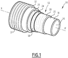
- a first flexible pipe 10 according to the invention is partially shown in Figure 1 .
- the flexible pipe 10 comprises a central section 12 shown in part in Figure 1 .
- the flexible pipe 10 delimits a central passage 16 for circulation of fluid, advantageously a fluid for hydraulic fracturing.
- the central passage 16 extends along the longitudinal direction X-X', between the upstream end and the downstream end of the flexible pipe 10.
- the flexible pipe 10 is for example intended to the circulation of a fluid under pressure for the hydraulic fracturing.
- the flexible pipe is typically disposed onshore between a wellhead and a manifold.
- the fluid is for example injected into a wellbore in case of hydraulic fracturing.
- Hydraulic fracturing also referred to "tracking” is a method consisting in injecting a fracking fluid at high pressure, such as 1000 bar (15000 psi), into a reservoir through a wellbore to increase the permeability of the reservoir and release oil and gas.
- the fracking fluid consists mainly in water.
- the fluid may comprise additional elements such as sand, and/or chemical components.
- the temperature of the fluid is the surrounding temperature of the flexible pipe. It is generally comprised between -20°C and 60°C.
- the flexible pipe 10 is intended to be disposed across a body of water (not shown) and in an installation for prospecting and exploitation of fluids, in particular hydrocarbons.
- the body of water is, for example, a sea, a lake or an ocean.
- the depth of the body of water in the area of the fluid prospecting and exploitation installation is for example between 500 m and 3, 000 m.
- the fluid prospecting and exploitation installation includes a surface assembly in particular a floating assembly and a bottom assembly (not represented) which are generally connected to each other by a flexible pipe 10.
- the flexible pipe 10 is preferably a pipe that is "not bonded” (referred to by the term “unbonded” as per the accepted English terminology).
- At least two tensile armor layers of the flexible pipe 10 are free to move longitudinally in relation to each other upon the bending or flexion of the pipe.
- all of the layers of the flexible pipe 10 are free to move relative to the other.
- the flexible pipe 10 is a bonded flexible pipe.
- the flexible pipe 10 is in particular a smooth bore pipe as described below.
- a pipe is considered as "smooth bore pipe" when the innermost sheath of the pipe defining the passage for the fluid is made of a polymeric material. In such a case, the flexible pipe 10 does not comprise an inner metal carcass.
- the flexible pipe 10 comprises a plurality of concentric layers around the longitudinal direction X-X', which extends continuously along the central section 12 between the upstream end and the downstream end of the flexible pipe 10, up to the end fittings 14 located at the ends of the flexible pipe 10.
- the flexible pipe 10 comprises at least one internal sheath 18 made of a polymer based material and designed to be used for confining in a sealed manner the transported fluid in the central passage 16.
- the internal sheath 18 is formed by the pressure sheath 20.
- the internal sheath 18 is formed by a protective polymeric sheath 34 disposed internally to the pressure sheath 20.
- the flexible pipe 10 further comprises at least one tensile armor layer 24, 25 disposed externally relative to the pressure sheath 20.
- the flexible pipe 10 in addition comprises a pressure vault 30 interposed between the pressure sheath 20 and the layer or layers of tensile armor 24, 25 and an exterior sheath 32, designed to ensure the protection of the flexible pipe 10.
- the flexible pipe 10 further comprises a carcass 37 disposed externally to the exterior sheath 32.
- the pressure sheath 20 is formed of polymer material, for example based on a polyolefin such as polyethylene, based on a polyamide such as PA11 or PA12, or based on fluorinated polymer such as polyvinylidene fluoride (PVDF).
- a polyolefin such as polyethylene
- a polyamide such as PA11 or PA12
- fluorinated polymer such as polyvinylidene fluoride (PVDF).
- the pressure sheath 20 is formed of an elastomer or a polyurethane.
- the thickness of the pressure sheath 20 is for example comprised between 5 mm and 20 mm.
- the pressure vault 30 is designed to absorb the forces related to the pressure prevailing within the interior of the pressure sheath 20. It is for example formed of a metal profiled wire wound helically around the sheath 20.
- the profiled wire generally has a complex geometry, in particular having a form shaped like a Z, T, U, K, X, S or I.
- the pressure vault 30 is helically wound with a short pitch around the pressure sheath 20, that is to say, with a helix angle having an absolute value close to 90°, typically comprised between 75° and 90°.
- the flexible pipe 10 comprises at least one armor layer 24, 25 formed of a helical winding of at least one elongated oxy element (wires) 38.
- the flexible pipe 10 includes a plurality of reinforcing armor layers 24, 25, in particular an interior armor layer 24, applied on to the pressure vault 30 and an exterior reinforcing oxy layer 25 around which is disposed the exterior sheath 32.
- the reinforcing armor layers 24, 25 allow withstanding the deformation created by the fluid under pressure circulating inside the flexible pipe.
- Each armor layer 24, 25, includes longitudinal reinforcing armor elements 38 wound with a long pitch around the longitudinal direction X-X' of the pipe 10.
- wound with a long pitch is used to indicate that the absolute value of the helix angle is less than 60°, and is typically comprised between 25° and 55°.
- the reinforcing armor elements 38 of a first armor layer 24 are generally wound at an angle in the opposite direction relative to the armor element 38 of a second armor layer 25.
- the winding angle of the reinforcing armor element 38 of the first armor layer 24 is equal to + ⁇ , ⁇ being comprised between 10° and 60°, in particular between 25° and 55°
- the winding angle of the reinforcing armor element 38 of the second arc layer 25 disposed in contact with the first armor layer 24 is for example - ⁇ , with ⁇ comprised between 10° and 60°, in particular between 25° and 55°.
- each layer of reinforcing armor 24, 25 is provided with at least one anti-wear layer (not shown) on which the layer 24, 25 is supported.
- the anti-wear strip (not shown) is for example made of plastic.
- the reinforcing armor elements 38 are for example made of metallic wire, notably steel wires, or by ribbon in composite material, for example ribbon reinforced by carbon fibers.
- the reinforcing armor elements 38 comprise end sections 40 inserted in the end fitting 14. Each end section 40 comprises a free end arranged in the end fitting 14.
- the exterior sheath 32 is intended to prevent the permeation of fluid from the exterior of the flexible pipe 10 to the interior. It is advantageously made of a polymer material, in particular based on a polyolefin, such as polyethylene or polypropylene, based on a polyamide, such as the PA11 or PA12, or based on a fluorinated polymer such as polyvinylidene fluoride (PVDF).
- a polyolefin such as polyethylene or polypropylene
- a polyamide such as the PA11 or PA12
- PVDF polyvinylidene fluoride
- the thickness of the exterior sheath 32 is for example comprised between 5 mm and 15 mm.
- the carcass 37 when it is present, is formed for example of a profiled metal strip that is wound in a spiral.
- the spiral windings of the strip are advantageously interlocked into each other.
- the function of the carcass is to protect the exterior sheath 32 from tear, wear, abrasion and others external damages.
- the helical winding of the profiled metal sheet forming the carcass 37 is short pitched, that is to say it has a helix angle having an absolute value close to 90°, typically comprised between 75° and 90°, more particularly between 75° and 88°.
- the end fitting 14 comprises an end vault 42 and an outer cover 44 around the end vault 42.
- the outer cover 44 axially protrudes rearwards from the end vault 42.
- the outer cover 44 delimits with the end vault 42 and the pressure vault 30, a reception chamber 46 receiving the end sections 40 of the armors layers 24, 25.
- the end vault 42 defines an internal surface 48 in contact with the front region 36 of the internal sheath 18.
- the internal surface 48 comprises a front longitudinal part 50 extending along the X-X' direction.
- the end fitting 14 further comprises a front sealing assembly 54 arranged around the front region 36 of the internal sheath 18.
- the front sealing assembly 54 is arranged around the pressure sheath 20.
- the end fitting 14 further comprises a rear sealing assembly (not represented) arranged around the exterior sheath 32.
- the end vault 42 comprises a front region 43 comprising an end flange 45, a back region 47, covered by the outer cover 44, and an intermediate region 49 connecting the front region 43 to the back region 47.
- the end vault 42 is intended to connect the flexible pipe 10 to another end fitting 14 or to a terminal equipment, advantageously by the end flange 45.
- the outer cover 44 comprises a tubular peripheral wall 58 extending around the longitudinal direction X-X'.
- the peripheral wall 58 has a rear edge 60 extending axially rearwards beyond the end vault 42.
- the outer cover 44 delimits the reception chamber 46 radially outwards.
- the end vault 42 and a front region 62 of the pressure sheath 20 delimit the reception chamber 46 radially inwards.
- the reception chamber 46 is advantageously filed with a filling material intended to anchor the end sections 40 of the armor elements 38 inside the reception chamber 46.
- the filling material is for example a thermosetting resin such as an epoxy resin or a thermoplastic resin.
- the front sealing assembly 54 is arranged at the front of the end fitting 14. It is longitudinally spaced apart from the reception chamber 46, at the front of the reception chamber 46, in the front region 43.
- the front sealing assembly 54 comprises a cannula 64 supporting at least one part of the front region 36 of the pressure sheath 20 and an annular protrusion 66 arranged on the internal surface 48 of the end vault 42 and protruding toward the central passage 16, and more particularly arranged on the front part 50 of the internal surface 48 of the end vault 42.
- the front region 36 of the internal sheath 18 is circumferentially tightened between the protrusion 66 and the cannula 64.
- the protrusion 66 is integral with the end vault 42.
- the protrusion 66 is an annular element fixed to the internal surface 48 of the end vault 42.
- the protrusion 66 protrudes beyond the internal surface 48 of the end vault 42 toward the central passage 16 to a distance comprised between 50 mm and 300 mm.
- the front region 36 of the pressure sheath 20 is plastically deformed by the protrusion 66.
- the cannula 64 has a general tubular shape.
- the cannula 64 comprises a cylindrical front portion 68 and a rear truncated cone shape portion 70 connected to the front portion 68.
- the front portion 68 of the cannula 64 is arranged facing to the front part 50 of the internal surface 48 of the end vault 42.
- An exterior surface 72 of the front portion 68 of the cannula 64 and the front part 50 of the internal surface 48 of the end vault 42 are substantially concentric.
- the rear portion 70 of the cannula 66 allows a progressive radial spreading of the front region 36 of the pressure sheath 20 until the pressure sheath 20 covers the front portion 68 of the cannula 64.
- the cannula 64 has a longitudinal length comprised between 100 mm and 400 mm.
- the protrusion 66 is arranged facing to the front portion 68 of the cannula 64.
- the cannula 64 is made in metal.
- the cannula 64 is made of carbon or stainless steel.
- end fitting 14 may further comprise a longitudinal restraining element (not represented) for restraining the cannula 64 to the end vault 42.
- the rear sealing assembly (not represented) comprises for example a rear crimping ring for crimping the external sheath, and a rear clamping flange of the rear crimping ring, fixed to the outer cover 44.
- the method comprises providing a flexible pipe 10.
- a front region 36 of the internal sheath 18 is stripped from the pressure vault 30, the first and second armor layer 24, 25, the exterior sheath 32 and the carcass 37.
- the end sections 40 of the armoring layers 24, 25 are then prepared to be received in the reception chamber 46.
- the end sections 40 are dismissed from the front region 36 of the pressure sheath 20 and the pressure vault 30.
- the method comprises providing an end vault 42 as described above and fixing said end vault 42 over the at least one part of the front region 36 of the pressure sheath 20.
- the method comprises providing a cannula 64 as described above.
- the cannula 64 is then inserted in the central passage 16 for supporting the part of the front region 36 of the pressure sheath 20.
- the cannula 64 is pushed by a tooling than can be supported by the end vault 42 which will act as reaction point.
- the pressure sheath 20 is then circumferentially tightened between the protrusion 66 and the cannula 64.
- the cannula 64 When the cannula 64 is in place, the cannula 64 is not subject to any displacement thanks to the compressive forces applied by the rear portion 70 of the cannula 64 to the pressure sheath 20 during the mounting.
- the outer cover 44 in then arranged and fixed on the end vault 42.
- the reception chamber 46 is then filled with a filling material such as an epoxy resin or a thermoplastic resin.
- the reception chamber 46 is filled with a filling material prior to the insertion of the cannula.
- the method applies when the pressure sheath 20 is damaged either chemically or mechanically.
- the method comprises removing the cannula 64. This allows releasing the pressure sheath 20 from the end termination of the flexible pipe 10.
- a first way for removing the cannula 64 consists in extracting the cannula 64 by mechanical means. For example, grooves or holes are made in the cannula 64 to allow the engagement of a mechanical or hydraulic extractor tool. Activation of the tool disengages the cannula 64 and extracts the cannula 64 from the end fitting 14.
- longitudinal cuts are performed on the entire length of the cannula 64 to split it in sectors, for example two, preferably three or more sectors. This allows releasing the compressive forces exerted by pressure sheath and provides a sufficient clearance to remove the cannula 64 by sectors.
- Another way to extract the cannula 64 consists in setting a watertight packer in the cannula 64.
- the flexible pipe 10 is then filled with water and pressurized to push the cannula 64 out.
- the method then comprises extracting the pressure sheath 20 from the flexible pipe 10 from an end of the end fitting 14.
- a first way to extract the pressure sheath 20 consists in inserting a thin cannula between an exterior surface of the pressure sheath 20 and the end fitting 14. This cannula acts as a support element for a tool expanding on it. The tool, such as a packer or a mechanical expander is then able to grip the pressure sheath 20.
- Two tools are installed on both end of the flexible pipe 10 to exert tension on the pressure sheath 20 and decrease the diameter of the pressure sheath 20.
- Controlled tension winches can be used on both end of the flexible pipe for controlling the tension exerted on the pressure sheath 20.
- a come along is used on the pullout side and a braking system is used on the other side for short sections of pipe.
- a tool comprising multiple cutting blades may be pulled through the flexible pipe 10 to segment the pressure sheath 20. Then, the pressure sheath 20 may be easily released segment by segment.
- the method for replacing the pressure sheath 20 then comprises inserting a new pressure sheath 20.
- a first way for inserting the new pressure sheath 20 consists in collapsing the pressure sheath 20 in a U shape to create an artificial smaller diameter.
- the collapsed pressure sheath 20 is inserted along the entire length of the flexible pipe 10. Then, mechanical reshaping for example using a pig allows giving the pressure sheath 20 its original tubular shape.
- hydraulic reshaping is used.
- the pressure sheath 20 is filled with a pressurized liquid to give its original tubular shape.
- FIG. 3 An alternative way for inserting the new pressure sheath 20 is shown in Figure 3 .
- the pressure sheath 20 is elongated using a die or a roller box 92 at one end of the flexible pipe 10 corresponding to the insertion point.
- a pulling force is applied to one end of the pressure sheath 20.
- a winch 94 is attached to the end of the pressure sheath 20.
- the die or the roller box 92 acts as a breaking force working against the winch 94.
- a lubricant is applied on the pressure sheath 20 may be used for helping the insertion of the pressure sheath 20 in the flexible pipe 10.
- a pig is used to pull the pressure sheath 20 inside the flexible pipe.
- Another alternative way to for inserting the new pressure sheath 20 comprises inserting a pressure sheath 20 having a smaller diameter compared to the interior diameter of the pressure vault 30. Then, hydraulic expansion of the pressure sheath 20 is performed using hydrostatic pressure. In addition, heating the pressure sheath 20 may facilitate the radial expansion of the sheath 20.
- the end fitting 14 according to the invention is particularly advantageous because by performing the crimping operation from the front end of the end fitting 14 with a protrusion 66 defined in the end vault 42, allows reducing the number of elements in the end fitting 14, reducing the size and the weight of the end fitting 14.
- FIG. 4 A second embodiment of an end fitting 14 according to the invention is shown in Figure 4 .
- the description of this embodiment is made by difference compared to the first embodiment.
- the flexible pipe 10 comprises both a protective polymeric sheath 34 and a pressure sheath 20 disposed externally to the protective polymeric sheath 34.
- the protective polymeric sheath 34 is arranged in an inner surface of the pressure sheath 20.
- the protective polymeric sheath 34 protects the pressure sheath 20 from the fluid circulating in the central passage 16.
- the protective polymeric sheath 34 is particularly advantageous to protect the inner surface of the pressure sheath 20 in case the fluid circulating in the central passage 16 comprises elements such as sand grain which may damage the inner surface of the pressure sheath 20.
- the protective polymeric sheath 34 is formed for example by a polymeric material for example based on a polyolefin such as a polyethylene or based on a polyamide such as a PA11 or a PA12 or based on a fluorinated polymer such as polyvinylidene fluoride (PVDF).
- the protective polymeric sheath 34 is formed by an elastomer based materials or a polyurethane.
- the thickness of the protective polymeric sheath 34 is for example comprised between 5 mm and 30 mm.
- the protective polymeric sheath 34 comprises a front region 36 inserted in the end fitting 14.
- the protective polymeric sheath 34 may either co-extruded with the pressure sheath 20 or fabricated separately.
- the internal polymeric sheath 18 is formed by the protective polymeric sheath 34.
- the front sealing assembly 54 is arranged around the protective polymeric sheath 34.
- the end fitting further comprises an intermediate sealing assembly 56 around the pressure sheath 20.
- the intermediate sealing assembly 56 comprises an intermediate crimping flange 78, an intermediate crimping ring 80 and an intermediate supporting cannula 82 interposed between the protective polymeric sheath 34 and the pressure sheath 20.
- the intermediate crimping ring 80 is interposed between a rear surface 84 of the intermediate crimping flange 78 and the pressure sheath 20.
- the pressure sheath 20 relies on the intermediate supporting cannula 82.
- the end fitting 14 comprises a test port 76 defined in the end vault 42 and arranged between the protrusion 66 and the intermediate sealing assembly 56.
- the test port 76 allows testing the crimping effectiveness and thus the tightness of the end fitting 14.
- the test port 76 is located in the intermediate region 49.
- the test port 76 allows controlling the integrity of the flexible pipe 10. Indeed, for example, it allows measuring the pressure between the pressure sheath 20 and the protective polymeric sheath 34. When the protective polymeric sheath 34 is damaged, the pressure in the test port 76 increases indicating that the protective polymeric sheath has to be changed.
- the method for mounting an end fitting 14 according to the second embodiment further comprises fixing the intermediate sealing assembly 56 and activating it by clamping onto the end vault 42.
- a second way for extracting the protective polymeric sheath 34 is to deform the protective polymeric sheath 34 into a collapsed U shape. This may be done by pressurizing the annular space defined between the pressure sheath 20 and the protective polymeric sheath 34 to collapse the protective polymeric sheath 34.
- FIG. 5 A third embodiment of an end fitting 14 according to the invention is shown in Figure 5 .
- the description of this embodiment is made by difference compared to the first embodiment.
- the end fitting 14 further comprises an interior ring 86 on which the end sections 40 of the first armor layer 24 exteriorly bear on, an intermediate ring 88 interposed between the end sections 40 of the first armor layer 24 and the end sections 40 of the second armor layer 25, and an exterior ring 90 disposed in external support on the end sections 40 of the second armor layer 25.
- the internal surface 48 of the end vault 42 comprises a front longitudinal part 50 connected to a rear part 96.
- the rear part 96 extends along a direction intersecting the longitudinal direction X-X'.
- the rear portion 70 of the cannula 64 is arranged facing to the rear part 96 of the internal surface 48 of the end vault 42.
- An exterior surface 72 of the front portion 68 of the cannula 64 and the front part 50 of the internal surface 48 of the end vault 42 are substantially concentric.
- An exterior surface 74 of the rear portion 70 of the cannula 64 and the rear part 96 of the internal surface 48 of the end vault 42 are substantially concentric.
- FIG. 6 A fourth embodiment of the invention is shown in Figure 6 . This embodiment is described by differences compared to the embodiment of Figure 5 .
- the end fitting 14 further comprises a longitudinal restraining element 98 for restraining the cannula 64 to the end vault 42.
- the restraining element 98 is for example a pin 100 inserted through the cannula 64 into the end vault 42 as shown in Figure 6 .
- the restraining element 98 comprises a ring set in the end vault 42 or a protrusion part of the cannula 64 protruding towards the end vault 42 inserted in a circular groove defined in the end vault 42.
- Such a restraining element 98 may also be used in the embodiment of Figure 2 .
- FIG. 7 A fifth embodiment of the invention is shown in Figure 7 . This embodiment is described by differences to the embodiment of Figure 5 .
- the front sealing assembly 54 comprises two annular protrusions 66 arranged along the longitudinal direction X-X'.
- the two protrusions 66 have the same geometrical features.
- One of the protrusions 66 radially extends in the intermediate region 49 of the end vault 42.
- the front sealing assembly 54 may comprise a test port 76 defined in the end vault 42 arranged between the two protrusions 66.
- the test port allows controlling the sealing of an inner space delimited by the internal surface 48 of the end vault 42 and an external surface of the internal sheath 18, between the annular protrusions 66.
Landscapes
- Engineering & Computer Science (AREA)
- General Engineering & Computer Science (AREA)
- Mechanical Engineering (AREA)
- Rigid Pipes And Flexible Pipes (AREA)
- Lining Or Joining Of Plastics Or The Like (AREA)
Abstract
Description
- The present invention relates to an end fitting of a flexible pipe for conveying a fluid comprising:
- an end vault and an outer cover fixed around the end vault and delimiting a reception chamber,
- at least a front region of an internal polymeric sheath defining a central passage for conveying the fluid, the central passage extending according to a longitudinal direction,
- at least end sections of at least one tensile armor layer arranged around the internal polymeric sheath, the end sections being arranged in the reception chamber,
- a front sealing assembly arranged around the front region of the internal polymeric sheath.
- The pipe is in particular a flexible pipe of a type that is not bonded (or "unbonded") intended for conveying a fluid such as a fracking fluid.
- Hydraulic fracturing also referred to "tracking" is a method consisting in injecting a fracking fluid at high pressure into a reservoir through a wellbore to increase the permeability of the reservoir and release oil and gas.
- The fracking fluid consists mainly in water. The fluid may also comprise additional components such as sand, and/or chemical components.
- In variant, the fluid conveyed in the flexible pipe is oil and/or gaz.
- The flexible pipe is generally formed of a plurality of layers that are concentric and superposed. It is considered "unbonded" within the scope and purpose of the present invention since the tensile armor layers are free to move relative to each other during a flexion of the flexible pipe, i.e. the tensile armor layers are not embedded in a bonding material such as an elastomer.
- The pipe is in particular a smooth bore pipe. A pipe is considered as "smooth bore pipe" when the innermost sheath of the pipe defining the passage for the fluid is made of a polymeric material. This type of flexible pipe does not comprise an inner metal carcass.
- The flexible pipe is generally disposed onshore, between a first surface assembly designed for collecting the fluid used onshore and a second surface assembly designed for distributing the fluid. For example, the flexible pipe is disposed between a manifold and a wellhead.
- The fluid is for example injected into a wellbore for hydraulic fracturing.
- In such a case, the flexible pipe may have a short length comprised between 1 m and 100 m, preferably between 1 m and 20 m.
- In a variant, the flexible pipe is disposed across a body of water, between a bottom assembly designed for collecting the fluid used at the bottom of the body of water and a floating surface assembly designed for collecting and distributing the fluid. The surface assembly may be a semi-submersible platform, an FPSO (Floating Production Storage and Offloading unit) or another unit.
- Typically, the flexible pipe comprises end fittings for connecting them to an adjacent structure such as a manifold or a wellhead, or to another flexible pipe.
- The classical method used to seal the internal sheath of an unbonded flexible pipe is to crimp it between an inner and an outer metallic layers.
- The inner metallic layer provides mechanical support to the internal sheath to allow a proper contact and to support the plastic deformation of the internal sheath.
- The outer metallic layer is typically a monocone penetrating the internal polymeric sheath. The compression of the internal sheath prevents fluid and gas migration and provides a leak-proof barrier. The monocone is pressed downward and plastically deformed by pushing it forward on a slope machined in the vault of the end fitting. This is done by tightening a flange on the vault which allows creating the forces necessary for the plastic deformation of the monocone and of the internal sheath. A second leak path between the vault and the monocone is sealed by the metal to metal contact that remains energized by the tightening of the crimping flange.
- The metal to metal seal requires that the surfaces in contact have a proper finish with no scratch. Therefore, a great care is required during the assembling process of the end fitting. Moreover, due to the fact that the crimping operation of the flange is made from the rear side of the vault, there is some interference with the armors of the flexible pipe that have to be laid back to allow for proper access. This leads to a global lengthening of the end fitting.
- An object of the invention is to overcome these drawbacks and to provide an end fitting allowing a good fluid tightness involving less elements in order to reduce the length and the weight of the end fitting.
- To this end, the subject-matter of the invention relates to an end fitting of the aforementioned type, wherein the front sealing assembly comprises a cannula supporting at least one part of the front region of the internal polymeric sheath and at least one annular protrusion arranged on an internal surface of the end vault protruding toward the central passage, the at least one part of the front region of the internal polymeric sheath being circumferentially tightened between the at least one protrusion and the cannula. The end fitting according to the invention may comprise on or more of the following features, taken into consideration in isolation or in accordance with any technically possible combination:
- the at least one protrusion is integral with the end vault;
- the at least one protrusion is an annular ring;
- the at least one part of the front region of the internal polymeric sheath is plastically deformed by the protrusion;
- the front sealing assembly comprises two annular protrusions set apart along the longitudinal direction;
- the end fitting comprises a test port defined in the end vault for controlling the sealing of an inner space delimited by the internal surface of the end vault and an external surface of the internal polymeric sheath, between the annular protrusions;
- the front sealing assembly comprises a restraining element for maintaining the cannula fixed to the end vault;
- the internal polymeric sheath is a polymeric pressure sheath intended to tightly confine the fluid conveyed by the central passage, the polymeric pressure sheath advantageously having a thickness comprised between 5 mm and 20 mm;
- the end fitting further comprises a front region of a pressure sheath, the internal polymeric sheath being a protective polymeric sheath intended to protect the pressure sheath, the pressure sheath being arranged around the protective polymeric sheath;
- the end fitting further comprises an intermediate sealing assembly arranged around the front region of the pressure sheath.
- The subject-matter of the invention also relates to a flexible pipe comprising:
- at least an internal polymeric sheath defining a central passage for conveying the fluid, the central passage extending according to a longitudinal direction,
- at least one tensile armor layer arranged around the internal polymeric sheath, and
- an end fitting as described above.
- The flexible pipe may comprise one or several of the following features, taken into consideration in isolation or in accordance with any technically possible combination:
- the flexible pipe comprises an end fitting as described above and a pressure sheath intended to tightly confine the fluid conveyed by the central passage, the internal polymeric sheath being formed by the pressure sheath;
- the flexible pipe comprises an end fitting as described above, a pressure sheath and a protective polymeric sheath intended to protect the pressure sheath and intended to tightly confine the fluid conveyed by the central passage, the pressure sheath being arranged around the protective polymeric sheath, the internal sheath being formed by the protective polymeric sheath.
- The invention also relates to a method for mounting an end fitting as described above, the method comprising the following steps:
- providing a flexible pipe,
- providing an end vault comprising at least one annular protrusion arranged on the internal surface of the end vault, the at least one protrusion protruding toward the central passage,
- fixing the end fault over at least one part of the front region of the internal sheath,
- providing a cannula,
- inserting the cannula for supporting the at least one part of the front region of the internal sheath to circumferentially tightened said at least one part of the front region of the internal sheath between the at least one annular protrusion and the cannula.
- Finally, the subject-matter of the invention relates to a method for replacing an internal sheath in a flexible pipe as described above, the method comprising the following steps:
- removing the cannula,
- extracting the internal sheath from the flexible pipe from an end of the end fitting,
- inserting a new internal sheath by the end of the end fitting,
- inserting a new cannula into the internal sheath to circumferentially tighten the at least one part of the front region of the internal sheath being between the at least one protrusion of the front sealing assembly and the cannula.
- The invention will be better understood upon reading the description which will follow, given solely by way of example, and with reference being made to the accompanying drawings in which:
-
Figure 1 is a partially stripped down perspective view of a section of a flexible pipe according to the invention; -
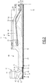
Figure 2 is a schematic view, taken along a median cross section, of an end fitting according to a first embodiment of the invention; -
Figure 3 is a schematic view of a step of a method for replacing a protective polymeric sheath according to the invention. -
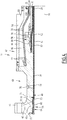
Figure 4 is a schematic view, taken along a median cross section, of an end fitting according to a second embodiment of the invention; -
Figure 5 is a schematic view, taken along a median cross section, of an end fitting according to third embodiment of the invention; -
Figure 6 is a schematic view, taken along a median cross section, of an end fitting according to a fourth embodiment of the invention; and -
Figure 7 is a schematic view, taken along a median cross section, of an end fitting according to a fifth embodiment of the invention. - In the following, the terms "exterior" and "interior" are to be understood generally in a radial manner relative to a longitudinal direction X-X' of the pipe. The term "exterior" is to be understood as being relatively further away radially from the longitudinal direction X-X' and the term "interior" is to be understood as being relatively closer radially to the longitudinal direction X-X' of the pipe.
- A first
flexible pipe 10 according to the invention is partially shown inFigure 1 . - The
flexible pipe 10 comprises acentral section 12 shown in part inFigure 1 . - With reference to
Figure 1 , theflexible pipe 10 delimits acentral passage 16 for circulation of fluid, advantageously a fluid for hydraulic fracturing. Thecentral passage 16 extends along the longitudinal direction X-X', between the upstream end and the downstream end of theflexible pipe 10. - The
flexible pipe 10 is for example intended to the circulation of a fluid under pressure for the hydraulic fracturing. - The flexible pipe is typically disposed onshore between a wellhead and a manifold. The fluid is for example injected into a wellbore in case of hydraulic fracturing.
- Hydraulic fracturing also referred to "tracking" is a method consisting in injecting a fracking fluid at high pressure, such as 1000 bar (15000 psi), into a reservoir through a wellbore to increase the permeability of the reservoir and release oil and gas.
- The fracking fluid consists mainly in water. The fluid may comprise additional elements such as sand, and/or chemical components.
- The temperature of the fluid is the surrounding temperature of the flexible pipe. It is generally comprised between -20°C and 60°C.
- In a variant, the
flexible pipe 10 is intended to be disposed across a body of water (not shown) and in an installation for prospecting and exploitation of fluids, in particular hydrocarbons. - The body of water is, for example, a sea, a lake or an ocean. The depth of the body of water in the area of the fluid prospecting and exploitation installation is for example between 500 m and 3, 000 m.
- The fluid prospecting and exploitation installation includes a surface assembly in particular a floating assembly and a bottom assembly (not represented) which are generally connected to each other by a
flexible pipe 10. - The
flexible pipe 10 is preferably a pipe that is "not bonded" (referred to by the term "unbonded" as per the accepted English terminology). - At least two tensile armor layers of the
flexible pipe 10 are free to move longitudinally in relation to each other upon the bending or flexion of the pipe. Advantageously, all of the layers of theflexible pipe 10 are free to move relative to the other. In a variant, theflexible pipe 10 is a bonded flexible pipe. - The
flexible pipe 10 is in particular a smooth bore pipe as described below. A pipe is considered as "smooth bore pipe" when the innermost sheath of the pipe defining the passage for the fluid is made of a polymeric material. In such a case, theflexible pipe 10 does not comprise an inner metal carcass. - The
flexible pipe 10 comprises a plurality of concentric layers around the longitudinal direction X-X', which extends continuously along thecentral section 12 between the upstream end and the downstream end of theflexible pipe 10, up to theend fittings 14 located at the ends of theflexible pipe 10. - According to the invention, the
flexible pipe 10 comprises at least oneinternal sheath 18 made of a polymer based material and designed to be used for confining in a sealed manner the transported fluid in thecentral passage 16. - As it will be described below, in a first embodiment of the invention (
Figures 1 and2 ), theinternal sheath 18 is formed by thepressure sheath 20. - In a second embodiment of the invention (
Figure 4 ), theinternal sheath 18 is formed by aprotective polymeric sheath 34 disposed internally to thepressure sheath 20. - Back to the first embodiment of the invention of
Figures 1 and2 , theflexible pipe 10 further comprises at least onetensile armor layer pressure sheath 20. - Advantageously, and according to the desired use, the
flexible pipe 10 in addition comprises apressure vault 30 interposed between thepressure sheath 20 and the layer or layers oftensile armor exterior sheath 32, designed to ensure the protection of theflexible pipe 10. - Preferably, the
flexible pipe 10 further comprises acarcass 37 disposed externally to theexterior sheath 32. - In a known manner, the
pressure sheath 20 is formed of polymer material, for example based on a polyolefin such as polyethylene, based on a polyamide such as PA11 or PA12, or based on fluorinated polymer such as polyvinylidene fluoride (PVDF). - In variant, the
pressure sheath 20 is formed of an elastomer or a polyurethane. - The thickness of the
pressure sheath 20 is for example comprised between 5 mm and 20 mm. - In the example of
Figure 1 , thepressure vault 30 is designed to absorb the forces related to the pressure prevailing within the interior of thepressure sheath 20. It is for example formed of a metal profiled wire wound helically around thesheath 20. The profiled wire generally has a complex geometry, in particular having a form shaped like a Z, T, U, K, X, S or I. - The
pressure vault 30 is helically wound with a short pitch around thepressure sheath 20, that is to say, with a helix angle having an absolute value close to 90°, typically comprised between 75° and 90°. - The
flexible pipe 10 according to the invention comprises at least onearmor layer - In the example shown in
Figure 1 , theflexible pipe 10 includes a plurality of reinforcingarmor layers interior armor layer 24, applied on to thepressure vault 30 and an exterior reinforcingamour layer 25 around which is disposed theexterior sheath 32. The reinforcingarmor layers - Each
armor layer armor elements 38 wound with a long pitch around the longitudinal direction X-X' of thepipe 10. - The term "wound with a long pitch", is used to indicate that the absolute value of the helix angle is less than 60°, and is typically comprised between 25° and 55°.
- The reinforcing
armor elements 38 of afirst armor layer 24 are generally wound at an angle in the opposite direction relative to thearmor element 38 of asecond armor layer 25. Thus, if the winding angle of the reinforcingarmor element 38 of thefirst armor layer 24 is equal to +α, α being comprised between 10° and 60°, in particular between 25° and 55°, the winding angle of the reinforcingarmor element 38 of thesecond amour layer 25 disposed in contact with thefirst armor layer 24 is for example -α, with α comprised between 10° and 60°, in particular between 25° and 55°. - Advantageously, and according to the desired use, each layer of reinforcing
armor layer - The reinforcing
armor elements 38 are for example made of metallic wire, notably steel wires, or by ribbon in composite material, for example ribbon reinforced by carbon fibers. - The reinforcing
armor elements 38 compriseend sections 40 inserted in the end fitting 14. Eachend section 40 comprises a free end arranged in the end fitting 14. - The
exterior sheath 32 is intended to prevent the permeation of fluid from the exterior of theflexible pipe 10 to the interior. It is advantageously made of a polymer material, in particular based on a polyolefin, such as polyethylene or polypropylene, based on a polyamide, such as the PA11 or PA12, or based on a fluorinated polymer such as polyvinylidene fluoride (PVDF). - The thickness of the
exterior sheath 32 is for example comprised between 5 mm and 15 mm. - The
carcass 37, when it is present, is formed for example of a profiled metal strip that is wound in a spiral. The spiral windings of the strip are advantageously interlocked into each other. The function of the carcass is to protect theexterior sheath 32 from tear, wear, abrasion and others external damages. - The helical winding of the profiled metal sheet forming the
carcass 37 is short pitched, that is to say it has a helix angle having an absolute value close to 90°, typically comprised between 75° and 90°, more particularly between 75° and 88°. - As shown for example in
Figure 2 , in addition to thefront region 36 of theinternal sheath 18, theend sections 40 of the armor layers 24, 25, the end fitting 14 comprises anend vault 42 and anouter cover 44 around theend vault 42. Theouter cover 44 axially protrudes rearwards from theend vault 42. Theouter cover 44 delimits with theend vault 42 and thepressure vault 30, areception chamber 46 receiving theend sections 40 of the armors layers 24, 25. - The
end vault 42 defines aninternal surface 48 in contact with thefront region 36 of theinternal sheath 18. - The
internal surface 48 comprises a frontlongitudinal part 50 extending along the X-X' direction. - The end fitting 14 further comprises a
front sealing assembly 54 arranged around thefront region 36 of theinternal sheath 18. In the embodiment ofFigure 1 , the front sealingassembly 54 is arranged around thepressure sheath 20. The end fitting 14 further comprises a rear sealing assembly (not represented) arranged around theexterior sheath 32. - The
end vault 42 comprises afront region 43 comprising anend flange 45, aback region 47, covered by theouter cover 44, and anintermediate region 49 connecting thefront region 43 to theback region 47. - In this example, the
end vault 42 is intended to connect theflexible pipe 10 to another end fitting 14 or to a terminal equipment, advantageously by theend flange 45. - The
outer cover 44 comprises a tubularperipheral wall 58 extending around the longitudinal direction X-X'. Theperipheral wall 58 has arear edge 60 extending axially rearwards beyond theend vault 42. - The
outer cover 44 delimits thereception chamber 46 radially outwards. Theend vault 42 and afront region 62 of thepressure sheath 20 delimit thereception chamber 46 radially inwards. - The
reception chamber 46 is advantageously filed with a filling material intended to anchor theend sections 40 of thearmor elements 38 inside thereception chamber 46. - The filling material is for example a thermosetting resin such as an epoxy resin or a thermoplastic resin.
- The
front sealing assembly 54 is arranged at the front of the end fitting 14. It is longitudinally spaced apart from thereception chamber 46, at the front of thereception chamber 46, in thefront region 43. - The
front sealing assembly 54 comprises acannula 64 supporting at least one part of thefront region 36 of thepressure sheath 20 and anannular protrusion 66 arranged on theinternal surface 48 of theend vault 42 and protruding toward thecentral passage 16, and more particularly arranged on thefront part 50 of theinternal surface 48 of theend vault 42. - The
front region 36 of theinternal sheath 18 is circumferentially tightened between theprotrusion 66 and thecannula 64. - Preferably, the
protrusion 66 is integral with theend vault 42. - In variant, the
protrusion 66 is an annular element fixed to theinternal surface 48 of theend vault 42. - Preferably, the
protrusion 66 protrudes beyond theinternal surface 48 of theend vault 42 toward thecentral passage 16 to a distance comprised between 50 mm and 300 mm. - The
front region 36 of thepressure sheath 20 is plastically deformed by theprotrusion 66. - The
cannula 64 has a general tubular shape. Thecannula 64 comprises acylindrical front portion 68 and a rear truncatedcone shape portion 70 connected to thefront portion 68. - The
front portion 68 of thecannula 64 is arranged facing to thefront part 50 of theinternal surface 48 of theend vault 42. - An
exterior surface 72 of thefront portion 68 of thecannula 64 and thefront part 50 of theinternal surface 48 of theend vault 42 are substantially concentric. - The
rear portion 70 of thecannula 66 allows a progressive radial spreading of thefront region 36 of thepressure sheath 20 until thepressure sheath 20 covers thefront portion 68 of thecannula 64. - The
cannula 64 has a longitudinal length comprised between 100 mm and 400 mm. - The
protrusion 66 is arranged facing to thefront portion 68 of thecannula 64. - The
cannula 64 is made in metal. For example, thecannula 64 is made of carbon or stainless steel. - In addition, the end fitting 14 may further comprise a longitudinal restraining element (not represented) for restraining the
cannula 64 to theend vault 42. - The rear sealing assembly (not represented) comprises for example a rear crimping ring for crimping the external sheath, and a rear clamping flange of the rear crimping ring, fixed to the
outer cover 44. - A method for mounting an end fitting 14 of the aforementioned type will now be described.
- Initially, the method comprises providing a
flexible pipe 10. Afront region 36 of theinternal sheath 18 is stripped from thepressure vault 30, the first andsecond armor layer exterior sheath 32 and thecarcass 37. - In the embodiment of
Figure 2 , theend sections 40 of the armoring layers 24, 25 are then prepared to be received in thereception chamber 46. Theend sections 40 are dismissed from thefront region 36 of thepressure sheath 20 and thepressure vault 30. - Then, the method comprises providing an
end vault 42 as described above and fixing saidend vault 42 over the at least one part of thefront region 36 of thepressure sheath 20. - The method comprises providing a
cannula 64 as described above. - The
cannula 64 is then inserted in thecentral passage 16 for supporting the part of thefront region 36 of thepressure sheath 20. - For example, the
cannula 64 is pushed by a tooling than can be supported by theend vault 42 which will act as reaction point. - The
pressure sheath 20 is then circumferentially tightened between theprotrusion 66 and thecannula 64. - When the
cannula 64 is in place, thecannula 64 is not subject to any displacement thanks to the compressive forces applied by therear portion 70 of thecannula 64 to thepressure sheath 20 during the mounting. - The
outer cover 44 in then arranged and fixed on theend vault 42. - Finally, the rear sealing assembly is fixed and activated by clamping on the
outer cover 44. - The
reception chamber 46 is then filled with a filling material such as an epoxy resin or a thermoplastic resin. - Alternatively, the
reception chamber 46 is filled with a filling material prior to the insertion of the cannula. - A method for replacing a
pressure sheath 20 of aflexible pipe 10 as described above will be described. - The method applies when the
pressure sheath 20 is damaged either chemically or mechanically. - First, the method comprises removing the
cannula 64. This allows releasing thepressure sheath 20 from the end termination of theflexible pipe 10. - A first way for removing the
cannula 64 consists in extracting thecannula 64 by mechanical means. For example, grooves or holes are made in thecannula 64 to allow the engagement of a mechanical or hydraulic extractor tool. Activation of the tool disengages thecannula 64 and extracts thecannula 64 from the end fitting 14. - In case the
cannula 64 is extensively damaged, longitudinal cuts are performed on the entire length of thecannula 64 to split it in sectors, for example two, preferably three or more sectors. This allows releasing the compressive forces exerted by pressure sheath and provides a sufficient clearance to remove thecannula 64 by sectors. - The risk to damage the end fitting 14 is limited since the
pressure sheath 20 protects theinterior surface 48 of theend vault 42 from the tool. - Another way to extract the
cannula 64 consists in setting a watertight packer in thecannula 64. Theflexible pipe 10 is then filled with water and pressurized to push thecannula 64 out. - The method then comprises extracting the
pressure sheath 20 from theflexible pipe 10 from an end of the end fitting 14. - A first way to extract the
pressure sheath 20 consists in inserting a thin cannula between an exterior surface of thepressure sheath 20 and the end fitting 14. This cannula acts as a support element for a tool expanding on it. The tool, such as a packer or a mechanical expander is then able to grip thepressure sheath 20. - Two tools are installed on both end of the
flexible pipe 10 to exert tension on thepressure sheath 20 and decrease the diameter of thepressure sheath 20. Controlled tension winches can be used on both end of the flexible pipe for controlling the tension exerted on thepressure sheath 20. Alternatively, a come along is used on the pullout side and a braking system is used on the other side for short sections of pipe. - In a second variant, a tool comprising multiple cutting blades may be pulled through the
flexible pipe 10 to segment thepressure sheath 20. Then, thepressure sheath 20 may be easily released segment by segment. - The method for replacing the
pressure sheath 20 then comprises inserting anew pressure sheath 20. - A first way for inserting the
new pressure sheath 20 consists in collapsing thepressure sheath 20 in a U shape to create an artificial smaller diameter. Thecollapsed pressure sheath 20 is inserted along the entire length of theflexible pipe 10. Then, mechanical reshaping for example using a pig allows giving thepressure sheath 20 its original tubular shape. - In variant, hydraulic reshaping is used. The
pressure sheath 20 is filled with a pressurized liquid to give its original tubular shape. - An alternative way for inserting the
new pressure sheath 20 is shown inFigure 3 . Thepressure sheath 20 is elongated using a die or aroller box 92 at one end of theflexible pipe 10 corresponding to the insertion point. A pulling force is applied to one end of thepressure sheath 20. For example, awinch 94 is attached to the end of thepressure sheath 20. By applying a tensile force on thepressure sheath 20, thepressure sheath 20 elongates and reduces in diameter. The die or theroller box 92 acts as a breaking force working against thewinch 94. - Once the
pressure sheath 20 is placed inside theflexible pipe 10, the tension is released and thepressure sheath 20 springs back to its original diameter. - In variant, a lubricant is applied on the
pressure sheath 20 may be used for helping the insertion of thepressure sheath 20 in theflexible pipe 10. - In variant, a pig is used to pull the
pressure sheath 20 inside the flexible pipe. - Another alternative way to for inserting the
new pressure sheath 20 comprises inserting apressure sheath 20 having a smaller diameter compared to the interior diameter of thepressure vault 30. Then, hydraulic expansion of thepressure sheath 20 is performed using hydrostatic pressure. In addition, heating thepressure sheath 20 may facilitate the radial expansion of thesheath 20. - The end fitting 14 according to the invention is particularly advantageous because by performing the crimping operation from the front end of the end fitting 14 with a
protrusion 66 defined in theend vault 42, allows reducing the number of elements in the end fitting 14, reducing the size and the weight of the end fitting 14. - A second embodiment of an end fitting 14 according to the invention is shown in
Figure 4 . The description of this embodiment is made by difference compared to the first embodiment. - In this embodiment, the
flexible pipe 10 comprises both aprotective polymeric sheath 34 and apressure sheath 20 disposed externally to theprotective polymeric sheath 34. - The
protective polymeric sheath 34 is arranged in an inner surface of thepressure sheath 20. - The
protective polymeric sheath 34 protects thepressure sheath 20 from the fluid circulating in thecentral passage 16. Theprotective polymeric sheath 34 is particularly advantageous to protect the inner surface of thepressure sheath 20 in case the fluid circulating in thecentral passage 16 comprises elements such as sand grain which may damage the inner surface of thepressure sheath 20. - The
protective polymeric sheath 34 is formed for example by a polymeric material for example based on a polyolefin such as a polyethylene or based on a polyamide such as a PA11 or a PA12 or based on a fluorinated polymer such as polyvinylidene fluoride (PVDF). In variant, theprotective polymeric sheath 34 is formed by an elastomer based materials or a polyurethane. - The thickness of the
protective polymeric sheath 34 is for example comprised between 5 mm and 30 mm. - The
protective polymeric sheath 34 comprises afront region 36 inserted in the end fitting 14. - The
protective polymeric sheath 34 may either co-extruded with thepressure sheath 20 or fabricated separately. - In this embodiment, the
internal polymeric sheath 18 is formed by theprotective polymeric sheath 34. - Therefore, as visible in
Figure 4 , the front sealingassembly 54 is arranged around theprotective polymeric sheath 34. - The end fitting further comprises an
intermediate sealing assembly 56 around thepressure sheath 20. - The
intermediate sealing assembly 56 comprises an intermediate crimpingflange 78, an intermediate crimpingring 80 and an intermediate supportingcannula 82 interposed between theprotective polymeric sheath 34 and thepressure sheath 20. - The intermediate crimping
ring 80 is interposed between arear surface 84 of the intermediate crimpingflange 78 and thepressure sheath 20. - The
pressure sheath 20 relies on the intermediate supportingcannula 82. - Preferably, as illustrated in
Figure 4 , the end fitting 14 comprises atest port 76 defined in theend vault 42 and arranged between theprotrusion 66 and theintermediate sealing assembly 56. Thetest port 76 allows testing the crimping effectiveness and thus the tightness of the end fitting 14. Here thetest port 76 is located in theintermediate region 49. - In this embodiment, the
test port 76 allows controlling the integrity of theflexible pipe 10. Indeed, for example, it allows measuring the pressure between thepressure sheath 20 and theprotective polymeric sheath 34. When theprotective polymeric sheath 34 is damaged, the pressure in thetest port 76 increases indicating that the protective polymeric sheath has to be changed. - The method for mounting an end fitting 14 according to the second embodiment further comprises fixing the
intermediate sealing assembly 56 and activating it by clamping onto theend vault 42. - The various ways for removing the
protective polymeric sheath 34 or for inserting a newprotective polymeric sheath 34 are similar to those described above for thepressure sheath 20 in the first embodiment. - In addition, a second way for extracting the
protective polymeric sheath 34 is to deform theprotective polymeric sheath 34 into a collapsed U shape. This may be done by pressurizing the annular space defined between thepressure sheath 20 and theprotective polymeric sheath 34 to collapse theprotective polymeric sheath 34. - A third embodiment of an end fitting 14 according to the invention is shown in
Figure 5 . The description of this embodiment is made by difference compared to the first embodiment. - In this embodiment, inside the
reception chamber 46, the end fitting 14 further comprises aninterior ring 86 on which theend sections 40 of thefirst armor layer 24 exteriorly bear on, anintermediate ring 88 interposed between theend sections 40 of thefirst armor layer 24 and theend sections 40 of thesecond armor layer 25, and anexterior ring 90 disposed in external support on theend sections 40 of thesecond armor layer 25. - The
internal surface 48 of theend vault 42 comprises a frontlongitudinal part 50 connected to arear part 96. Therear part 96 extends along a direction intersecting the longitudinal direction X-X'. - The
rear portion 70 of thecannula 64 is arranged facing to therear part 96 of theinternal surface 48 of theend vault 42. - An
exterior surface 72 of thefront portion 68 of thecannula 64 and thefront part 50 of theinternal surface 48 of theend vault 42 are substantially concentric. - An
exterior surface 74 of therear portion 70 of thecannula 64 and therear part 96 of theinternal surface 48 of theend vault 42 are substantially concentric. - A fourth embodiment of the invention is shown in
Figure 6 . This embodiment is described by differences compared to the embodiment ofFigure 5 . - The end fitting 14 further comprises a
longitudinal restraining element 98 for restraining thecannula 64 to theend vault 42. The restrainingelement 98 is for example apin 100 inserted through thecannula 64 into theend vault 42 as shown inFigure 6 . - In variant, the restraining
element 98 comprises a ring set in theend vault 42 or a protrusion part of thecannula 64 protruding towards theend vault 42 inserted in a circular groove defined in theend vault 42. - Such a restraining
element 98 may also be used in the embodiment ofFigure 2 . - A fifth embodiment of the invention is shown in
Figure 7 . This embodiment is described by differences to the embodiment ofFigure 5 . - The
front sealing assembly 54 comprises twoannular protrusions 66 arranged along the longitudinal direction X-X'. Preferably, the twoprotrusions 66 have the same geometrical features. - One of the
protrusions 66 radially extends in theintermediate region 49 of theend vault 42. - In addition, the front sealing
assembly 54 may comprise atest port 76 defined in theend vault 42 arranged between the twoprotrusions 66. The test port allows controlling the sealing of an inner space delimited by theinternal surface 48 of theend vault 42 and an external surface of theinternal sheath 18, between theannular protrusions 66.
Claims (15)
- End fitting (14) of a flexible pipe (14) for conveying a fluid comprising:- an end vault (42) and an outer cover (44) fixed around the end vault (42) and delimiting a reception chamber (46),- at least a front region (36) of an internal polymeric sheath (18) defining a central passage (16) for conveying the fluid, the central passage (16) extending according to a longitudinal direction (X-X'),- at least end sections (40) of at least one tensile armor layer (24, 25) arranged around the internal polymeric sheath (18), the end sections (40) being arranged in the reception chamber (46),- a front sealing assembly (54) arranged around the front region (36) of the internal polymeric sheath (18),characterized in that the front sealing assembly (54) comprises a cannula (64) supporting at least one part of the front region (36) of the internal polymeric sheath (18) and at least one annular protrusion (66) arranged on an internal surface (48) of the end vault (42) protruding toward the central passage (16), the at least one part of the front region (36) of the internal polymeric sheath (18) being circumferentially tightened between the at least one protrusion (66) and the cannula (64).
- End fitting (14) according to claim 1, wherein the at least one protrusion (66) is integral with the end vault (42).
- End fitting (14) according to claim 1 or 2, wherein the at least one protrusion (66) is an annular ring.
- End fitting (14) according to any one of preceding claims, wherein the at least one part of the front region (36) of the internal polymeric sheath (18) is plastically deformed by the protrusion (66).
- End fitting (14) according to any one of preceding claims, wherein the front sealing assembly (54) comprises two annular protrusions (66) set apart along the longitudinal direction (X-X').
- End fitting (14) according to claim 5, further comprising a test port (76) defined in the end vault (42) for controlling the sealing of an inner space delimited by the internal surface (48) of the end vault (42) and an external surface of the internal polymeric sheath (18), between the annular protrusions (66).
- End fitting (14) according to any one of the preceding claims, wherein the front sealing assembly (54) comprises a restraining element (96) for maintaining the cannula (64) fixed to the end vault (42).
- End fitting (14) according to any one of the preceding claims, wherein the internal polymeric sheath (18) is a polymeric pressure sheath (20) intended to tightly confine the fluid conveyed by the central passage (16), the polymeric pressure sheath (20) advantageously having a thickness comprised between 5 mm and 20 mm.
- End fitting (14) according to any one of claims 1 to 7, further comprising a front region (62) of a pressure sheath (20), the internal polymeric sheath (18) being a protective polymeric sheath (34) intended to protect the pressure sheath (20), the pressure sheath (20) being arranged around the protective polymeric sheath (34).
- End fitting (14) according to claim 9, further comprising an intermediate sealing assembly (56) arranged around the front region (62) of the pressure sheath (20).
- Flexible pipe (10) for conveying a fluid comprising:- at least an internal polymeric sheath (18) defining a central passage (16) for conveying the fluid, the central passage (16) extending according to a longitudinal direction (X-X'),- at least one tensile armor layer (24, 25) arranged around the internal polymeric sheath (18), and- an end fitting (14) according to any one of claims 1 to 10.
- Flexible pipe (10) according to claim 11, comprising an end fitting (14) according to any one of claim 1 to 8 and a pressure sheath (20) intended to tightly confine the fluid conveyed by the central passage (16), the internal polymeric sheath (18) being formed by the pressure sheath (20).
- Flexible pipe according to claim 11, comprising an end fitting (14) according to claim 9 or 10, a pressure sheath (20) and a protective polymeric sheath (34) intended to protect the pressure sheath (20) and intended to tightly confine the fluid conveyed by the central passage (16), the pressure sheath (20) being arranged around the protective polymeric sheath (34), the internal sheath (18) being formed by the protective polymeric sheath (34).
- Method for mounting an end fitting (14) according to any one of claims 1 to 10, the method comprising the following steps:- providing a flexible pipe (10),- providing an end vault (42) comprising at least one annular protrusion (66) arranged on the internal surface (48) of the end vault (42), the at least one protrusion (66) protruding toward the central passage (16),- fixing the end fault (42) over at least one part of the front region (36) of the internal sheath (18),- providing a cannula (64),- inserting the cannula (64) for supporting the at least one part of the front region (36) of the internal sheath (18) to circumferentially tightened said at least one part of the front region (36) of the internal sheath (18) between the at least one annular protrusion (66) and the cannula (64).
- Method for replacing an internal sheath (18) in a flexible pipe (10) according to claim 13, the method comprising the following steps:- removing the cannula (64),- extracting the internal sheath (18) from the flexible pipe (10) from an end of the end fitting (14),- inserting a new internal sheath (18) by the end of the end fitting (14),- inserting a new cannula (64) into the internal sheath (18) to circumferentially tighten the at least one part of the front region (36) of the internal sheath (18) being between the at least one protrusion (66) of the front sealing assembly (54) and the cannula (64).
Priority Applications (5)
| Application Number | Priority Date | Filing Date | Title |
|---|---|---|---|
| EP19306362.5A EP3809031A1 (en) | 2019-10-18 | 2019-10-18 | End fitting of a flexible pipe, associated flexible pipe and related methods |
| PCT/EP2020/079173 WO2021074366A1 (en) | 2019-10-18 | 2020-10-16 | End fitting of a flexible pipe, associated flexible pipe and related methods |
| US17/768,568 US12222055B2 (en) | 2019-10-18 | 2020-10-16 | End fitting of a flexible pipe, associated flexible pipe and related methods |
| AU2020367025A AU2020367025B2 (en) | 2019-10-18 | 2020-10-16 | End fitting of a flexible pipe, associated flexible pipe and related methods |
| BR112022007142A BR112022007142A2 (en) | 2019-10-18 | 2020-10-16 | END FITTING OF A FLEXIBLE TUBE FOR TRANSPORTING A FLUID, FLEXIBLE TUBE FOR TRANSPORTING A FLUID, METHOD FOR ASSEMBLY AN END FITTING AND METHOD FOR REPLACEMENT OF AN INNER SHEATH IN A FLEXIBLE TUBE |
Applications Claiming Priority (1)
| Application Number | Priority Date | Filing Date | Title |
|---|---|---|---|
| EP19306362.5A EP3809031A1 (en) | 2019-10-18 | 2019-10-18 | End fitting of a flexible pipe, associated flexible pipe and related methods |
Publications (1)
| Publication Number | Publication Date |
|---|---|
| EP3809031A1 true EP3809031A1 (en) | 2021-04-21 |
Family
ID=68581679
Family Applications (1)
| Application Number | Title | Priority Date | Filing Date |
|---|---|---|---|
| EP19306362.5A Pending EP3809031A1 (en) | 2019-10-18 | 2019-10-18 | End fitting of a flexible pipe, associated flexible pipe and related methods |
Country Status (5)
| Country | Link |
|---|---|
| US (1) | US12222055B2 (en) |
| EP (1) | EP3809031A1 (en) |
| AU (1) | AU2020367025B2 (en) |
| BR (1) | BR112022007142A2 (en) |
| WO (1) | WO2021074366A1 (en) |
Cited By (1)
| Publication number | Priority date | Publication date | Assignee | Title |
|---|---|---|---|---|
| WO2025021313A1 (en) * | 2023-07-27 | 2025-01-30 | Baker Hughes Energy Technology UK Limited | Method of terminating a flexible pipe body, an apparatus for terminaton and flexible pipe |
Citations (3)
| Publication number | Priority date | Publication date | Assignee | Title |
|---|---|---|---|---|
| US6923477B2 (en) * | 2000-11-08 | 2005-08-02 | Coflexip | End-fitting for flexible pipe |
| WO2014001238A1 (en) * | 2012-06-26 | 2014-01-03 | Wellstream International Limited | Sleeve member, end fitting assembly and method of assembly of flexible pipe |
| WO2018234790A1 (en) * | 2017-06-22 | 2018-12-27 | Magma Global Limited | TERMINAL FITTING FOR COMPOSITE PIPE |
Family Cites Families (3)
| Publication number | Priority date | Publication date | Assignee | Title |
|---|---|---|---|---|
| DE2541242A1 (en) * | 1975-09-12 | 1977-03-24 | Kabel Metallwerke Ghh | FITTING FOR A CORRUGATED PIPE |
| BRPI0408940B1 (en) | 2003-03-26 | 2018-10-09 | Ge Oil & Gas Uk Limited | end fitting for a hose, tube assembly and tube assembly mounting method |
| AU2013283532A1 (en) * | 2012-06-26 | 2015-01-22 | Ge Oil & Gas Uk Limited | Intermediate sealing for ultradeep water applications |
-
2019
- 2019-10-18 EP EP19306362.5A patent/EP3809031A1/en active Pending
-
2020
- 2020-10-16 WO PCT/EP2020/079173 patent/WO2021074366A1/en not_active Ceased
- 2020-10-16 US US17/768,568 patent/US12222055B2/en active Active
- 2020-10-16 BR BR112022007142A patent/BR112022007142A2/en active Search and Examination
- 2020-10-16 AU AU2020367025A patent/AU2020367025B2/en active Active
Patent Citations (3)
| Publication number | Priority date | Publication date | Assignee | Title |
|---|---|---|---|---|
| US6923477B2 (en) * | 2000-11-08 | 2005-08-02 | Coflexip | End-fitting for flexible pipe |
| WO2014001238A1 (en) * | 2012-06-26 | 2014-01-03 | Wellstream International Limited | Sleeve member, end fitting assembly and method of assembly of flexible pipe |
| WO2018234790A1 (en) * | 2017-06-22 | 2018-12-27 | Magma Global Limited | TERMINAL FITTING FOR COMPOSITE PIPE |
Cited By (1)
| Publication number | Priority date | Publication date | Assignee | Title |
|---|---|---|---|---|
| WO2025021313A1 (en) * | 2023-07-27 | 2025-01-30 | Baker Hughes Energy Technology UK Limited | Method of terminating a flexible pipe body, an apparatus for terminaton and flexible pipe |
Also Published As
| Publication number | Publication date |
|---|---|
| BR112022007142A2 (en) | 2022-06-28 |
| AU2020367025A1 (en) | 2022-05-05 |
| AU2020367025B2 (en) | 2026-02-26 |
| US12222055B2 (en) | 2025-02-11 |
| US20240102590A1 (en) | 2024-03-28 |
| WO2021074366A1 (en) | 2021-04-22 |
Similar Documents
| Publication | Publication Date | Title |
|---|---|---|
| US10451206B2 (en) | Connection end-piece of a flexible pipe for transporting fluid and associated method | |
| US6889718B2 (en) | Armoured, flexible pipe and use of same | |
| EP1867905B1 (en) | Radius control | |
| US11378207B2 (en) | Swaged pipe fitting systems and methods | |
| EP2864748B1 (en) | Assembly and seal test | |
| US10690275B2 (en) | Connection tip for a flexible line, and associated flexible line and mounting method | |
| EP2780621A1 (en) | End fitting for flexible pipe | |
| EP2864749B1 (en) | Flexible pipe and method of assembly of flexible pipe | |
| US10053267B2 (en) | Method for assembling an end-piece of a flexible pipe and associated pre-assembly | |
| US10406577B2 (en) | Improving the bending behaviour of mechanically-lined rigid pipe | |
| US12222055B2 (en) | End fitting of a flexible pipe, associated flexible pipe and related methods | |
| US20240384818A1 (en) | Flexible pipe for hydraulic fracturing applications | |
| OA21143A (en) | Swaged pipe fitting systems and methods. |
Legal Events
| Date | Code | Title | Description |
|---|---|---|---|
| PUAI | Public reference made under article 153(3) epc to a published international application that has entered the european phase |
Free format text: ORIGINAL CODE: 0009012 |
|
| STAA | Information on the status of an ep patent application or granted ep patent |
Free format text: STATUS: THE APPLICATION HAS BEEN PUBLISHED |
|
| AK | Designated contracting states |
Kind code of ref document: A1 Designated state(s): AL AT BE BG CH CY CZ DE DK EE ES FI FR GB GR HR HU IE IS IT LI LT LU LV MC MK MT NL NO PL PT RO RS SE SI SK SM TR |
|
| AX | Request for extension of the european patent |
Extension state: BA ME |
|
| RAP1 | Party data changed (applicant data changed or rights of an application transferred) |
Owner name: TECHNIP N-POWER |
|
| STAA | Information on the status of an ep patent application or granted ep patent |
Free format text: STATUS: REQUEST FOR EXAMINATION WAS MADE |
|
| 17P | Request for examination filed |
Effective date: 20210923 |
|
| RBV | Designated contracting states (corrected) |
Designated state(s): AL AT BE BG CH CY CZ DE DK EE ES FI FR GB GR HR HU IE IS IT LI LT LU LV MC MK MT NL NO PL PT RO RS SE SI SK SM TR |
|
| TPAC | Observations filed by third parties |
Free format text: ORIGINAL CODE: EPIDOSNTIPA |
|
| STAA | Information on the status of an ep patent application or granted ep patent |
Free format text: STATUS: EXAMINATION IS IN PROGRESS |
|
| 17Q | First examination report despatched |
Effective date: 20230224 |
|
| RAP3 | Party data changed (applicant data changed or rights of an application transferred) |
Owner name: TECHNIPFMC SUBSEA FRANCE |
|
| GRAP | Despatch of communication of intention to grant a patent |
Free format text: ORIGINAL CODE: EPIDOSNIGR1 |
|
| STAA | Information on the status of an ep patent application or granted ep patent |
Free format text: STATUS: GRANT OF PATENT IS INTENDED |
|
| INTG | Intention to grant announced |
Effective date: 20260204 |
|
| RIN1 | Information on inventor provided before grant (corrected) |
Inventor name: ESPINASSE, PHILIPPE |