EP3808969A1 - Fuel rail assembly and use of a sheet metal restrictor - Google Patents
Fuel rail assembly and use of a sheet metal restrictor Download PDFInfo
- Publication number
- EP3808969A1 EP3808969A1 EP19203351.2A EP19203351A EP3808969A1 EP 3808969 A1 EP3808969 A1 EP 3808969A1 EP 19203351 A EP19203351 A EP 19203351A EP 3808969 A1 EP3808969 A1 EP 3808969A1
- Authority
- EP
- European Patent Office
- Prior art keywords
- fuel
- sheet metal
- branch
- rail assembly
- restrictor
- Prior art date
- Legal status (The legal status is an assumption and is not a legal conclusion. Google has not performed a legal analysis and makes no representation as to the accuracy of the status listed.)
- Withdrawn
Links
- 239000000446 fuel Substances 0.000 title claims abstract description 219
- 229910052751 metal Inorganic materials 0.000 title claims abstract description 122
- 239000002184 metal Substances 0.000 title claims abstract description 121
- 239000012530 fluid Substances 0.000 claims abstract description 22
- 238000004891 communication Methods 0.000 claims abstract description 18
- 230000009467 reduction Effects 0.000 claims abstract description 3
- 238000005219 brazing Methods 0.000 claims description 33
- 238000005476 soldering Methods 0.000 claims description 23
- 238000003466 welding Methods 0.000 claims description 18
- RYGMFSIKBFXOCR-UHFFFAOYSA-N Copper Chemical group [Cu] RYGMFSIKBFXOCR-UHFFFAOYSA-N 0.000 claims description 10
- 230000007704 transition Effects 0.000 claims description 10
- 238000003825 pressing Methods 0.000 claims description 5
- 239000011796 hollow space material Substances 0.000 description 7
- 239000000463 material Substances 0.000 description 7
- 230000000712 assembly Effects 0.000 description 4
- 238000000429 assembly Methods 0.000 description 4
- 238000003780 insertion Methods 0.000 description 4
- 230000037431 insertion Effects 0.000 description 4
- 238000004519 manufacturing process Methods 0.000 description 4
- 238000005452 bending Methods 0.000 description 3
- 238000002485 combustion reaction Methods 0.000 description 3
- 230000004048 modification Effects 0.000 description 3
- 238000012986 modification Methods 0.000 description 3
- 239000012768 molten material Substances 0.000 description 3
- 230000000694 effects Effects 0.000 description 2
- 229910052802 copper Inorganic materials 0.000 description 1
- 239000010949 copper Substances 0.000 description 1
- 238000005520 cutting process Methods 0.000 description 1
- 230000001419 dependent effect Effects 0.000 description 1
- 238000005516 engineering process Methods 0.000 description 1
- 238000003754 machining Methods 0.000 description 1
- 210000002445 nipple Anatomy 0.000 description 1
- 230000010349 pulsation Effects 0.000 description 1
- 238000011144 upstream manufacturing Methods 0.000 description 1
Images




Classifications
-
- F—MECHANICAL ENGINEERING; LIGHTING; HEATING; WEAPONS; BLASTING
- F02—COMBUSTION ENGINES; HOT-GAS OR COMBUSTION-PRODUCT ENGINE PLANTS
- F02M—SUPPLYING COMBUSTION ENGINES IN GENERAL WITH COMBUSTIBLE MIXTURES OR CONSTITUENTS THEREOF
- F02M61/00—Fuel-injectors not provided for in groups F02M39/00 - F02M57/00 or F02M67/00
- F02M61/16—Details not provided for in, or of interest apart from, the apparatus of groups F02M61/02 - F02M61/14
- F02M61/168—Assembling; Disassembling; Manufacturing; Adjusting
-
- F—MECHANICAL ENGINEERING; LIGHTING; HEATING; WEAPONS; BLASTING
- F02—COMBUSTION ENGINES; HOT-GAS OR COMBUSTION-PRODUCT ENGINE PLANTS
- F02M—SUPPLYING COMBUSTION ENGINES IN GENERAL WITH COMBUSTIBLE MIXTURES OR CONSTITUENTS THEREOF
- F02M55/00—Fuel-injection apparatus characterised by their fuel conduits or their venting means; Arrangements of conduits between fuel tank and pump F02M37/00
- F02M55/004—Joints; Sealings
- F02M55/005—Joints; Sealings for high pressure conduits, e.g. connected to pump outlet or to injector inlet
-
- F—MECHANICAL ENGINEERING; LIGHTING; HEATING; WEAPONS; BLASTING
- F02—COMBUSTION ENGINES; HOT-GAS OR COMBUSTION-PRODUCT ENGINE PLANTS
- F02M—SUPPLYING COMBUSTION ENGINES IN GENERAL WITH COMBUSTIBLE MIXTURES OR CONSTITUENTS THEREOF
- F02M55/00—Fuel-injection apparatus characterised by their fuel conduits or their venting means; Arrangements of conduits between fuel tank and pump F02M37/00
- F02M55/02—Conduits between injection pumps and injectors, e.g. conduits between pump and common-rail or conduits between common-rail and injectors
- F02M55/025—Common rails
-
- F—MECHANICAL ENGINEERING; LIGHTING; HEATING; WEAPONS; BLASTING
- F02—COMBUSTION ENGINES; HOT-GAS OR COMBUSTION-PRODUCT ENGINE PLANTS
- F02M—SUPPLYING COMBUSTION ENGINES IN GENERAL WITH COMBUSTIBLE MIXTURES OR CONSTITUENTS THEREOF
- F02M2200/00—Details of fuel-injection apparatus, not otherwise provided for
- F02M2200/28—Details of throttles in fuel-injection apparatus
-
- F—MECHANICAL ENGINEERING; LIGHTING; HEATING; WEAPONS; BLASTING
- F02—COMBUSTION ENGINES; HOT-GAS OR COMBUSTION-PRODUCT ENGINE PLANTS
- F02M—SUPPLYING COMBUSTION ENGINES IN GENERAL WITH COMBUSTIBLE MIXTURES OR CONSTITUENTS THEREOF
- F02M2200/00—Details of fuel-injection apparatus, not otherwise provided for
- F02M2200/31—Fuel-injection apparatus having hydraulic pressure fluctuations damping elements
- F02M2200/315—Fuel-injection apparatus having hydraulic pressure fluctuations damping elements for damping fuel pressure fluctuations
Definitions
- the present invention refers to a fuel rail assembly, in particular for delivering a fuel to a plurality of fuel injectors, wherein the fuel rail assembly comprises a fuel reservoir having a casing and providing a plurality of branch-off holes in its casing, wherein the fuel rail assembly comprises a plurality of branch units each providing a respective fuel passage, wherein each of the branch units is connected to the fuel reservoir so that the fuel passage of each respective branch unit is in fluid communication with a respective branch off-hole of the branch-off holes of the fuel reservoir.
- the invention according to a second aspect refers to a use of a restrictor.
- an underlying object of a first aspect the present invention is to provide an improved fuel rail assembly.
- it is an object to improve a fuel rail assembly in such a manner that at least some or all of the above described disadvantages can be overcome.
- An object underlying to a second aspect of the present invention is to provide an advantageous use of a restrictor.
- a first aspect of the present invention provides a fuel rail assembly which comprises a plurality of sheet metal restrictors, wherein each sheet metal restrictor comprises a respective end wall and a respective side wall, wherein these end walls each include an orifice, and wherein a respective sheet metal restrictor of the sheet metal restrictors is mounted within a respective branch off-hole of the branch-off holes and/or within a respective fuel passage of the fuel passages (10) of the branch units.
- a sheet metal restrictor as suggested by the invention is a restrictor which is made of sheet metal.
- the sheet metal restrictors each provide an "orifice function" and hence may be denoted also as orifice creators or orifice creator elements or more generally as sheet metal elements.
- the sheet metal restrictors can be used in different parts of a fuel rail depending on the application needs; in principle they can be applied to any component in contact with fuel within a fuel rail assembly. Its usage and its combination with one or more other fuel rail components, as for example a thick tube, a main gallery, an injector cup, a tube adapter and a copper ring, may provide different advantages.
- the sheet metal restrictors may be easy to manufacture, like for example by deep drawing, cupping, stamping or the like.
- each sheet metal restrictor is made from only a single plate of sheet metal.
- each sheet metal restrictor may have a one-piece design.
- the size and the shape of sheet metal restrictors can be easily adapted to specific requirements, in particular regarding different sizes of components of a fuel rail assembly.
- the suggested sheet metal restrictors are applicable in more and in more different interface zones of the components of a fuel rail assembly. Also it is possible to easily use the sheet metal restrictors in different configurations by adapting its respective position and/or orientation within the fuel rail assembly.
- restrictors which, differing from the prior art, are made of sheet metal, are highly appropriate for its use in fuel rail assemblies in order to reduce pressure peaks in the fuel rail assembly which results in a better functionality of connected injectors and which also results in that in a fuel rail assembly mechanical stress caused by pressure pulsations is reduced.
- the thickness of the sheet metal of the sheet metal restrictor can be different, i.e. can be chosen depending on the individual requirements of an application or use.
- the invention may also avoid the known problem of orifice plugging. For this purpose, for example the position and/or the orientation of the sheet metal restrictor may be chosen such that the orifice is far away from the molten brazing material (or soldering material or the like) during mounting.
- the shape of the sheet metal restrictor in particular a bending radius of a transition zone between the end wall and the side wall, can be adapted to not allow the molten material to flow into the orifice.
- the fuel reservoir may be a main gallery or a thick tube or the like.
- Each branch unit may comprise one or more components like for example an injector cup, a pipe, a tube, an adapter, and/or the like. A number of components may be fixed to each other in a fluid-tight manner by providing an inner fuel passage.
- the orifice of the sheet metal restrictor extends across the end wall as a via hole. It may be formed in the end wall of the sheet metal restrictor for example by stam-ping.
- the end wall is circular wherein the side wall either continuously extends along an outer circumference of the sheet metal restrictor 12 or comprises a plurality of side wall segments which are arranged in a distributed manner along the outer circumference of the sheet metal restrictor.
- the side wall of a sheet metal restrictor may provide an interface zone of the sheet metal restrictor for fixing it to an interface zone of a wall section which surrounds a branch-off hole and/or to an interface zone of a wall section which surrounds at a least a cross section of a fuel passage.
- the side wall of a sheet metal restrictor has a cylindrical shape and/or a conical shape. It is preferred that a sheet metal restrictor comprises a transition region which is situated between the end wall and the side wall, wherein the transition region is curved within longitudinal cross sections of the sheet me-tal restrictor.
- the curved region may have an advantageous effect during a mounting of components of a fuel rail assembly for example by brazing; the curved region may prevent or at least hinder that molten brazing material (paste or e.g. copper of a copper ring) can reach and plug the orifice. This even may also apply, if the end wall of the sheet metal restrictor faces towards a brazing connection which is situated in only a short distance.
- a bending radius of the transition zone of the sheet metal restrictor can be different, i.e. can be varied depending on the requirements of an application.
- a big bending radius may provide a large pendentive to accommodate molten brazing material in order to avoid or hinder its movement to the orifice.
- the sheet metal restrictors may be easily manufactured in that they are made by deep drawing and/or by cutting and/or by stamping.
- the orifice extends through the end wall across the sheet metal plane.
- it is made by stamping or the like.
- the side wall of a sheet metal restrictor is fixed at a wall section which surrounds a branch-off hole and/or at a wall section which surrounds at least a cross section of a fuel passage of a branch unit by pressing and/or by one or more mechanical stops and/or by one of either welding or brazing or soldering.
- the side wall or its section may provide an interface zone for fixing the sheet metal restrictor.
- the interface zone for example may have a shape for limiting the contact to another component of the fuel rail assembly to which the sheet metal restrictor is fixed.
- the contact may for example be limited to one or more areas which (compared to other regions) are more relevant.
- For mounting of a sheet metal restrictor its insertion can be realized on different ways, depending on a specific application or use.
- features for facilitating its insertion into a hole or into a fuel passage may be a radius or a chamfer or a deformation or a machining or a combination of some of these possibilities, also depending on the manufacturing technology.
- a press-fit may be obtained for fixing the sheet metal restrictor at a predetermined position.
- a movement of the sheet metal restrictor within a branch unit may be allowed in case there are provided mechanical stops for keeping the sheet metal restrictor within a desired zone.
- the insertion for example may also be alleviated by a concial shape of the side wall.
- a sheet metal restrictor is mounted in a first component of the fuel rail assembly and that the first component is connected with a second component of the fuel rail assembly by a connection made by welding or brazing or soldering, wherein in particular the end wall of the sheet metal restrictor faces away from the second component. It is possible that a sheet metal restrictor is mounted within the branch-off hole or within the fuel passage in an orientation so that its end wall is situated either upstream or downstream with regard to its side wall.
- this for example provides the possibility that the end wall may face away from or alternatively may face towards a second component which is adjacent to a first component accommodates the sheet metal restrictor and which for example is fixed to the first component accommodating the sheet metal restrictor by welding or brazing or soldering.
- a distance between the orifice in the end wall and the connection made by for example welding or brazing or soldering can be increased in order to decrease and even minimize the risk that the orifice may be damaged and plugged by molten material.
- a branch unit comprises an adapter which includes a fuel conduit being comprised of the fuel passage, wherein the fuel conduit extends from an inlet section of the fuel conduit to an outlet section of the fuel conduit, wherein the adapter is directly or indirectly connected to the fuel reservoir by welding or brazing or soldering so that its fuel conduit is in fluid communication with one of the branch-off holes of the fuel reservoir, and wherein in particular the sheet metal restrictor is mounted within the fuel conduit, in particular within the inlet section of the fuel conduit or within the outlet section of the fuel conduit.
- a first contact wall of the adapter is fixed to the fuel reservoir, in particular to a wall section surrounding the respective branch-off hole, by welding or brazing or soldering, in particular by using a copper ring for brazing or soldering.
- each branch unit comprises a pipe which includes a hollow duct being comprised of the fuel passage, wherein the hollow duct extends from an inlet section of the hollow duct to an outlet section of the hollow duct, wherein the pipe is directly or indirectly connected to the adapter by welding or brazing or soldering, in particular by using a copper ring for brazing or soldering, so that its hollow duct is in fluid communication with the fuel conduit of the adapter, and in particular wherein the sheet metal restrictor is mounted within the hollow duct, in particular within the inlet section of the hollow duct or within the outlet section of the hollow duct.
- the adapter has a bore, wherein an end section of the pipe is inserted into the bore in the adapter and is fixed within the bore by welding or brazing or soldering.
- a branch unit comprises an injector cup which has an end wall wherein the end wall surrounds a via hole being comprised of the fuel passage, and either in that the injector cup is directly or indirectly connected to the fuel reservoir by welding or brazing or soldering, in particular by using a copper ring, so that its via hole is in fluid communication with one of the branch-off holes of the fuel reservoir, wherein the sheet metal restrictor is mounted within the via hole, or in that the injector cup is directly or indirectly connected to the adapter by welding or brazing or soldering, in particular by using a copper ring, so that its via hole is in fluid communication with the fluid conduit of the adapter.
- the orifice of a sheet metal restrictor has a hollow cross-section area which is smaller compared to any other hollow cross-section area of the fuel passage within which the sheet metal restrictor is mounted or which branches from the branch-off hole within which the sheet metal restrictor is mounted.
- the diameter of the orifice may have a value of 15 - 25 percent (e. g. 20 percent), of an external diameter of the sheet metal restrictor.
- the orifice may be formed by stamping for example centrally in the end wall of the sheet metal restrictor.
- the dimension (in particular the diameter) and the position of the internal hole of the orifice can be different depending on the respective application.
- each branch units of a fuel rail assembly have a same structure and that its respective sheet metal restrictor is mounted in a same manner.
- the invention suggests an use for reduction of pressure peaks in a fuel rail assembly
- the fuel rail assembly comprises a fuel reservoir having a casing and providing a plurality of branch-off holes in its casing
- the fuel rail assembly comprises a plurality of branch units each providing a respective fuel passage
- each of the branch units is connected to the fuel reservoir so that the fuel passage of each respective branch unit is in fluid communication with a respective branch-off hole of the branch-off holes of the fuel reservoir
- the restrictor is a sheet metal restrictor, wherein the sheet metal restrictor comprises an end wall and a side wall, wherein the end wall includes an orifice and wherein the sheet metal restrictor is mounted within one of the branch-off holes and/or within the fuel passage of the respective branch unit.
- a plurality of sheet metal restrictors is used in a respective manner corresponding to each other.
- FIG. 1 A first exemplary embodiment of a fuel rail assembly 1 according to the invention will be described with reference to figures 1 - 4 .
- the fuel assembly 1 comprises a fuel reservoir 2 which has a casing 3.
- the casing 3 are a plurality of branch-off holes 4, although only one branch-off hole 4 is shown by the figures.
- Figures 1 and 2 schematically indicate that only a longitudinal section, which is an end section, of the fuel rail assembly 1 is depicted.
- figure 3 shows a branch unit 5 of the fuel rail assembly 1 wherein in the example the branch unit 5 consists only of an injector cup 6.
- the fuel reservoir 2 is in a shape of a main gallery.
- its inner hollow space 7 may be used to distribute fuel to a plurality of branch-off holes 4 which in the example are spaced from each other along a longitudinal direction L of the fuel reservoir 2.
- the fuel rail assembly 1 may be used to feed fuel to fuel injectors (not shown in the figures) of an internal combustion engine in particular of a motor vehicle (also not shown in the figures).
- the branch-off hole 4 is in fluid communication with the inner hollow space 7.
- the injector cup 6 has an end wall 8 which surrounds a via hole 9.
- the injector cup 6, which in the example forms the branch unit 5, provides a fuel passage 10 in its interior, wherein the via hole 9 is part of the fuel passage 10.
- an insert end of a fuel injector as known to a skilled person may be pushed into the hollow space of the injector cup 6 in a tightened manner in order to feed fuel to the fuel injector.
- the branch unit 5 is connected to the fuel reservoir 2 so that the fuel passage 10 is in fluid communication with the depicted branch-off hole 4 and accordingly with the hollow space 7 within the main gallery (fuel reservoir 2).
- the injector cup 6 is directly connected to the casing 3 of the fuel reservoir 2 by a brazed connection 11, i. e. by brazing.
- the injector cup 6 is fixed to the casing 3 so that its via hole 9 is in fluid communication with the branch-off hole 4.
- the fuel rail assembly 1 comprises a plurality of sheet metal restrictors 12. Although figures 1 - 4 show only one of them, the number of the sheet metal restrictors 12 corresponds to the number of branch-off holes 4 which also corresponds to the number of branch units 5.
- the sheet metal restrictor 12 is made of a thin plate of sheet metal.
- Figure 4 shows in more detail that the sheet metal restrictor 12 comprises an end wall 13 and a side wall 14.
- the end wall 13 has a circular shape. In its center an orifice 15 extends across the plane of the sheet metal for providing a through hole.
- the side wall 14 continuously extends along an outer circumference of the sheet metal restrictor 12 around a central axis A and has a rotationally symmetric cylindrical shape.
- the side wall 14 is connected to the end wall 13 by a transition region 16.
- the transition region 16 is curved.
- the curvature is schematically denoted by a radius r.
- the cup-like form of the sheet metal restrictors 12 is formed by deep drawing of a plate of a metal sheet; the orifice 15 is made by stamping.
- each sheet metal restrictor 12 is mounted within one of the branch-off holes 4.
- the side wall 14 of the sheet metal restrictor 12 is fixed at a wall section 17 which surrounds the branch-off hole 4(see figures 3 and 4 ) by pressing the side wall 14 in a radial outward direction in order to create a press-fit 18.
- the fuel reservoir 2 can be considered as a first component of the fuel rail assembly 1 and the injector cup 6 can be considered as a second component 20.
- the sheet metal restrictor 12 is mounted in the first component 19 which is connected with the second component 20 by the brazed connection 11, wherein in the example the end wall 13 faces away from the second component 20, i. e.
- a diameter of the via hole 9 is smaller compared to a diameter of the branch-off hole 4.
- a ring shoulder 21 is formed which, as an additional security feature, provides an axial mechanical stop for the sheet metal restrictor 12 for the unlikely case that it may release from the wall section 17.
- the hollow cross-section area of the orifice 15 is smaller compared to any other hollow cross-section area of the fuel passage 10.
- the described first exemplary embodiment of a fuel rail assembly 1 is side mounted wherein the injectors are in line.
- the sheet metal restrictor 12 is situated so that the fluid (i. e. fuel) is forced to pass through the orifice 15 before reaching the injector cup 6.
- the fuel rail assembly 1 is fixed to an engine head (not shown in the figures) by a number of brackets 23.
- Each bracket 23 provides a through hole 24.
- the through hole 24 may serve for holding a fastener which may be fixed to the engine head (not shown in the figures).
- FIG. 5 - 8 A second exemplary embodiment of a fuel rail assembly 1 according to the present invention is shown by figure 5 - 8 .
- Figures 5 and 6 show a first bracket 23 having a through hole 24 which may be used for fixing the fuel rail assembly 1 for example at an engine head of an internal combustion engine (not shown). From the figures it is clear that, again, only a longitudinal section of the fuel reservoir 2 is depicted. Hence, a longitudinal section of the fuel rail assembly 1 which is not shown by the figures but which adjoins the shown section at the right side of figure 5 comprises additional brackets 23. Accordingly, figure 7 does not only depict a cross section along the sectional plane VII - VII of figure 5 but in its background also depicts a second bracket (also denoted by 23) of the fuel rail assembly 1.
- FIGS 7 and 8 show a difference of the second exemplary embodiment from the first exemplary embodiment of figures 1 - 4 .
- the difference is that each sheet metal restrictor 12 is mounted within the via hole 9 which is formed in the end wall 8 of the injector cup 6 the via hole belongs to, i. e. is comprised of, the respective fuel passage 10.
- each sheet metal restrictor 12 is mounted within one of the fuel passages 10 of the branch units 5. Even if, on mounting the fuel rail assembly 1, the sheet metal restrictor 12 is pressed into the via hole 9 before the end wall 8 is connected to the fuel reservoir 2 by the brazed connection 11, on performing the brazing there is only a reduced risk that molten brazing material may reach or even plug the orifice 15.
- the distance between the brazed connection 11 and the orifice 15 is less compared to the first embodiment the risk is nevertheless reduced by the curved form of the transition region 16; because of the curved shape a circular hollow pocket is formed which may accommodate and hence stop any molten brazing material before reaching the orifice 15.
- the side wall 14 of the sheet metal restrictor 12 is fixed at a wall section 25 which surrounds a cross section of the via hole 9, i. e. which surrounds a local cross section of the fuel passage 10 of the branch unit 5.
- the fixture is achieved by pressing the side wall 14 in an outward radial direction against the annular wall section 25 in order to create a press-fit 18.
- each branch unit 5 comprises not only an injector cup 6 but in addition an adapter 26.
- the adapter 26 includes a fuel conduit 27.
- the via hole 9 and the fuel conduit 27 belong to the fuel passage 10.
- the fuel conduit 27 extends from an inlet section 28 of the fuel conduit 27 to an outlet section 29 of the fuel conduit 27.
- the adapter 26 is directly connected to the fuel reservoir 2 by a brazed connection 11 so that its fuel conduit 27 is in fluid communication with the adjacent branch-off hole 4.
- each sheet metal restrictor 12 is fixed in one of the branch-off holes 4.
- the orientation of the sheet metal restrictor 12 is inverse so that the end wall 13 faces to the outside, i. e. to the adapter 26.
- the sheet metal restrictor 12 could be attached alternatively at another position of the fuel rail assembly 1.
- the injector cup 6 for example may be fixed to the adapter 26 by an additional brazed connection 11.
- the fuel rail assembly 1 comprises a number of brackets 23 which are fixed to the fuel reservoir 2 by a respective brazed connection 11 (all brazed connections are denoted by the reference number 11).
- a respective bracket 23 is mounted adjacent to an adapter 26.
- a bended plate 30 is fixed both to the bracket 23 and to the adapter 26 by respective brazed connections 11.
- a fourth exemplary embodiment of a fuel rail assembly 1 according to the present is described with regard to figures 13 - 15 .
- the fuel rail assembly 1 is centrally mounted.
- the sheet metal restrictor 12 again is mounted within a branch-off hole 4 of the fuel reservoir 2 which also again is in a shape of a main gallery.
- the fluid i. e. the fuel
- the adapter 26 and the pipe 31 belong to the branch unit 5.
- the fuel conduit 27 of the adapter 26 belongs to the fuel passage 10 of the branch unit 5.
- the pipe 31 includes a hollow duct 32 which also belongs to the fuel passage 10.
- the hollow duct 32 extends from an inlet section 33 to an outlet section 34.
- the pipe 31 is directly connected to the adapter 26 by means of a brazed connection 11 so that the hollow duct 32 is in fluid communication with the fuel conduit 27 of the adapter 26, with the branch-off hole 4 and with the hollow space 7 of the main gallery.
- the sheet metal restrictor 12 could be attached for example to the adapter 26 or to the pipe 31 (i. e. within the fuel passage 10 of the branch unit 5) instead of mounting it in branch-off hole 4 of the fuel reservoir 2.
- the end section of the pipe 31 which corresponds to the inlet section of its duct 32 is inserted into a bore 35 of the adapter 26 and is fixed therein by a brazed connection 11.
Landscapes
- Engineering & Computer Science (AREA)
- Chemical & Material Sciences (AREA)
- Combustion & Propulsion (AREA)
- Mechanical Engineering (AREA)
- General Engineering & Computer Science (AREA)
- Manufacturing & Machinery (AREA)
- Fuel-Injection Apparatus (AREA)
Abstract
Description
- The present invention refers to a fuel rail
assembly, in particular for delivering a fuel to a plurality of fuel injectors, wherein the fuel rail assembly comprises a fuel reservoir having a casing and providing a plurality of branch-off holes in its casing, wherein the fuel rail assembly comprises a plurality of branch units each providing a respective fuel passage, wherein each of the branch units is connected to the fuel reservoir so that the fuel passage of each respective branch unit is in fluid communication with a respective branch off-hole of the branch-off holes of the fuel reservoir. Further, the invention according to a second aspect refers to a use of a restrictor. - Regarding fuel rail assemblies (also denoted as common rail assemblies) of internal combustion engines it is known that in operation pressure peaks may occur in the fuel. The pressure peaks may have a negative impact on the function of fuel injectors which are connected to the fuel rail assembly. In addition, the pressure peaks may cause additional mechanical stresses in the components, in particular within the fuel reservoir (which e. g. may be a main gallery). In the past this problem has been solved by increasing the total internal volume of the fuel rail. However this implies higher dimensions and higher costs. Another known solution is the introduction of a small orifice directly in one of the components involved within the fuel path. For example, it is known to form an orifice with a dedicated diameter directly in a tube adapter or in a nipple of an injector cup. However, a problem of this solution is that because of a frequently short distance to an intended adjacent brazed connection there is a risk that during brazing the molten material reaches the orifice so that the orifice is plugged and the component is a scrap. Alternative solutions use separate elements for providing a short orifice within the fuel path in order to dampen the pressure peaks, however these components are complicate and expensive in manufacturing and are specified to be used only in a predetermined position of the fuel rail assembly.
- Based on this background an underlying object of a first aspect the present invention is to provide an improved fuel rail assembly. In particular, it is an object to improve a fuel rail assembly in such a manner that at least some or all of the above described disadvantages can be overcome. An object underlying to a second aspect of the present invention is to provide an advantageous use of a restrictor.
- In order to solve the above mentioned first object a first aspect of the present invention provides a fuel rail assembly which comprises a plurality of sheet metal restrictors, wherein each sheet metal restrictor comprises a respective end wall and a respective side wall, wherein these end walls each include an orifice, and wherein a respective sheet metal restrictor of the sheet metal restrictors is mounted within a respective branch off-hole of the branch-off holes and/or within a respective fuel passage of the fuel passages (10) of the branch units.
- A sheet metal restrictor as suggested by the invention is a restrictor which is made of sheet metal. The sheet metal restrictors each provide an "orifice function" and hence may be denoted also as orifice creators or orifice creator elements or more generally as sheet metal elements. The sheet metal restrictors can be used in different parts of a fuel rail depending on the application needs; in principle they can be applied to any component in contact with fuel within a fuel rail assembly. Its usage and its combination with one or more other fuel rail components, as for example a thick tube, a main gallery, an injector cup, a tube adapter and a copper ring, may provide different advantages. The sheet metal restrictors may be easy to manufacture, like for example by deep drawing, cupping, stamping or the like. Preferably, each sheet metal restrictor is made from only a single plate of sheet metal. Preferably, each sheet metal restrictor may have a one-piece design. Regarding its manufacturing from sheet metal, advantageously the size and the shape of sheet metal restrictors can be easily adapted to specific requirements, in particular regarding different sizes of components of a fuel rail assembly. Accordingly, compared to conventional restrictors of fuel rail assemblies, the suggested sheet metal restrictors are applicable in more and in more different interface zones of the components of a fuel rail assembly. Also it is possible to easily use the sheet metal restrictors in different configurations by adapting its respective position and/or orientation within the fuel rail assembly. Nevertheless, it has been found that restrictors which, differing from the prior art, are made of sheet metal, are highly appropriate for its use in fuel rail assemblies in order to reduce pressure peaks in the fuel rail assembly which results in a better functionality of connected injectors and which also results in that in a fuel rail assembly mechanical stress caused by pressure pulsations is reduced. The thickness of the sheet metal of the sheet metal restrictor can be different, i.e. can be chosen depending on the individual requirements of an application or use. Furthermore, the invention may also avoid the known problem of orifice plugging. For this purpose, for example the position and/or the orientation of the sheet metal restrictor may be chosen such that the orifice is far away from the molten brazing material (or soldering material or the like) during mounting. By alternative or by combination the shape of the sheet metal restrictor, in particular a bending radius of a transition zone between the end wall and the side wall, can be adapted to not allow the molten material to flow into the orifice. The fuel reservoir, depending on the embodiment, for example may be a main gallery or a thick tube or the like. Each branch unit may comprise one or more components like for example an injector cup, a pipe, a tube, an adapter, and/or the like. A number of components may be fixed to each other in a fluid-tight manner by providing an inner fuel passage. The orifice of the sheet metal restrictor extends across the end wall as a via hole. It may be formed in the end wall of the sheet metal restrictor for example by stam-ping.
- There are many further possibilities for perfor-ming preferred modifications: It is preferred that the end wall is circular wherein the side wall either continuously extends along an outer circumference of the
sheet metal restrictor 12 or comprises a plurality of side wall segments which are arranged in a distributed manner along the outer circumference of the sheet metal restrictor. The side wall of a sheet metal restrictor may provide an interface zone of the sheet metal restrictor for fixing it to an interface zone of a wall section which surrounds a branch-off hole and/or to an interface zone of a wall section which surrounds at a least a cross section of a fuel passage. - In an embodiment it is provided that the side wall of a sheet metal restrictor has a cylindrical shape and/or a conical shape. It is preferred that a sheet metal restrictor comprises a transition region which is situated between the end wall and the side wall, wherein the transition region is curved within longitudinal cross sections of the sheet me-tal restrictor. The curved region may have an advantageous effect during a mounting of components of a fuel rail assembly for example by brazing; the curved region may prevent or at least hinder that molten brazing material (paste or e.g. copper of a copper ring) can reach and plug the orifice. This even may also apply, if the end wall of the sheet metal restrictor faces towards a brazing connection which is situated in only a short distance. In particular for this purpose, a bending radius of the transition zone of the sheet metal restrictor can be different, i.e. can be varied depending on the requirements of an application. A big bending radius may provide a large pendentive to accommodate molten brazing material in order to avoid or hinder its movement to the orifice.
- The sheet metal restrictors may be easily manufactured in that they are made by deep drawing and/or by cutting and/or by stamping. Preferably, the orifice extends through the end wall across the sheet metal plane. Preferably it is made by stamping or the like.
- It is preferred that the side wall of a sheet metal restrictor is fixed at a wall section which surrounds a branch-off hole and/or at a wall section which surrounds at least a cross section of a fuel passage of a branch unit by pressing and/or by one or more mechanical stops and/or by one of either welding or brazing or soldering. The side wall or its section may provide an interface zone for fixing the sheet metal restrictor. The interface zone for example may have a shape for limiting the contact to another component of the fuel rail assembly to which the sheet metal restrictor is fixed. The contact may for example be limited to one or more areas which (compared to other regions) are more relevant. For mounting of a sheet metal restrictor, its insertion can be realized on different ways, depending on a specific application or use. For example, features for facilitating its insertion into a hole or into a fuel passage may be a radius or a chamfer or a deformation or a machining or a combination of some of these possibilities, also depending on the manufacturing technology. By pressing the side wall of the sheet metal restrictor in a radial direction within a branch-off hole and/or within a fuel passage during or after insertion of the sheet metal restrictor into such hollow space a press-fit may be obtained for fixing the sheet metal restrictor at a predetermined position. On the other hand, a movement of the sheet metal restrictor within a branch unit may be allowed in case there are provided mechanical stops for keeping the sheet metal restrictor within a desired zone. The insertion for example may also be alleviated by a concial shape of the side wall.
- In a preferred embodiment it is provided that a sheet metal restrictor is mounted in a first component of the fuel rail assembly and that the first component is connected with a second component of the fuel rail assembly by a connection made by welding or brazing or soldering, wherein in particular the end wall of the sheet metal restrictor faces away from the second component. It is possible that a sheet metal restrictor is mounted within the branch-off hole or within the fuel passage in an orientation so that its end wall is situated either upstream or downstream with regard to its side wall. Depending on the requirements of each individual embodiment, this for example provides the possibility that the end wall may face away from or alternatively may face towards a second component which is adjacent to a first component accommodates the sheet metal restrictor and which for example is fixed to the first component accommodating the sheet metal restrictor by welding or brazing or soldering. By an orientation so that the end wall faces away from the second component in consequence a distance between the orifice in the end wall and the connection made by for example welding or brazing or soldering can be increased in order to decrease and even minimize the risk that the orifice may be damaged and plugged by molten material.
- In an exemplary embodiment it is provided that a branch unit comprises an adapter which includes a fuel conduit being comprised of the fuel passage, wherein the fuel conduit extends from an inlet section of the fuel conduit to an outlet section of the fuel conduit, wherein the adapter is directly or indirectly connected to the fuel reservoir by welding or brazing or soldering so that its fuel conduit is in fluid communication with one of the branch-off holes of the fuel reservoir, and wherein in particular the sheet metal restrictor is mounted within the fuel conduit, in particular within the inlet section of the fuel conduit or within the outlet section of the fuel conduit.
- It is preferred that a first contact wall of the adapter is fixed to the fuel reservoir, in particular to a wall section surrounding the respective branch-off hole, by welding or brazing or soldering, in particular by using a copper ring for brazing or soldering.
- In an exemplary embodiment it is provided that each branch unit comprises a pipe which includes a hollow duct being comprised of the fuel passage, wherein the hollow duct extends from an inlet section of the hollow duct to an outlet section of the hollow duct, wherein the pipe is directly or indirectly connected to the adapter by welding or brazing or soldering, in particular by using a copper ring for brazing or soldering, so that its hollow duct is in fluid communication with the fuel conduit of the adapter, and in particular wherein the sheet metal restrictor is mounted within the hollow duct, in particular within the inlet section of the hollow duct or within the outlet section of the hollow duct. For a functional embodiment it is suggested that the adapter has a bore, wherein an end section of the pipe is inserted into the bore in the adapter and is fixed within the bore by welding or brazing or soldering.
- It is possible that a branch unit comprises an injector cup which has an end wall wherein the end wall surrounds a via hole being comprised of the fuel passage, and either in that the injector cup is directly or indirectly connected to the fuel reservoir by welding or brazing or soldering, in particular by using a copper ring, so that its via hole is in fluid communication with one of the branch-off holes of the fuel reservoir, wherein the sheet metal restrictor is mounted within the via hole, or in that the injector cup is directly or indirectly connected to the adapter by welding or brazing or soldering, in particular by using a copper ring, so that its via hole is in fluid communication with the fluid conduit of the adapter.
- It is preferred that the orifice of a sheet metal restrictor has a hollow cross-section area which is smaller compared to any other hollow cross-section area of the fuel passage within which the sheet metal restrictor is mounted or which branches from the branch-off hole within which the sheet metal restrictor is mounted. For example, the diameter of the orifice may have a value of 15 - 25 percent (e. g. 20 percent), of an external diameter of the sheet metal restrictor. Preferably, the orifice may be formed by stamping for example centrally in the end wall of the sheet metal restrictor. Of course, the dimension (in particular the diameter) and the position of the internal hole of the orifice can be different depending on the respective application.
- It is possible that each branch units of a fuel rail assembly have a same structure and that its respective sheet metal restrictor is mounted in a same manner.
- Regarding an use of a restrictor, according to a second aspect the invention suggests an use for reduction of pressure peaks in a fuel rail assembly, wherein the fuel rail assembly comprises a fuel reservoir having a casing and providing a plurality of branch-off holes in its casing, wherein the fuel rail assembly comprises a plurality of branch units each providing a respective fuel passage, wherein each of the branch units is connected to the fuel reservoir so that the fuel passage of each respective branch unit is in fluid communication with a respective branch-off hole of the branch-off holes of the fuel reservoir wherein the restrictor is a sheet metal restrictor, wherein the sheet metal restrictor comprises an end wall and a side wall, wherein the end wall includes an orifice and wherein the sheet metal restrictor is mounted within one of the branch-off holes and/or within the fuel passage of the respective branch unit. Regarding technical effects and advantages as well as regarding possible modifications reference is made to the above description. It is preferred that a plurality of sheet metal restrictors is used in a respective manner corresponding to each other.
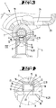
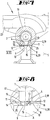
- Exemplary embodiments of the invention are explained in the following with regard to the attached fi-gures. The figures show:
- Fig. 1
- a side view of a section of a first exemplary embodiment of a fuel rail assembly in accordance to the invention;
- Fig.2
- a top view of the first exemplary embodiment in viewing direction II according to
figure 1 ; - Fig. 3
- a cross section of the first exemplary embodiment along sectional plane III - III in
Fig. 1 ; - Fig. 4
- an enlarged view of detail IV of
figure 3 ; - Fig. 5
- a side view of a section of a second exemplary embodiment of a fuel rail assembly according to the invention;
- Fig. 6
- a top view of the second exemplary embodiment in viewing direction VI according to
figure 5 ; - Fig. 7
- a cross section of the second exemplary embodiment along sectional plane VII - VII according to
figure 5 ; - Fig. 8
- an enlarged view of detail VIII of
figure 7 ; - Fig. 9
- a side view of a section of a third exemplary embodiment of a fuel rail assembly according to the invention;
- Fig. 10
- a top view of the third exemplary embodiment along viewing direction X according to
figure 9 ; - Fig. 11
- an enlarged cross section of the third exemplary embodiment along sectional plane XI - XI according to
figure 9 ; - Fig. 12
- an enlarged view of detail XII of
figure 11 ; - Fig. 13
- a side view of a section of a fourth exemplary embodiment of a fuel rail assembly according to the invention;
- Fig. 14
- an enlarged partial cross section of the fourth exemplary embodiment along sectional plane XIV - XIV according to
figure 13 and - Fig. 15
- an enlarged view of detail XV of
figure 14 . - A first exemplary embodiment of a fuel rail assembly 1 according to the invention will be described with reference to
figures 1 - 4 . The fuel assembly 1 comprises afuel reservoir 2 which has a casing 3. In the casing 3 are a plurality of branch-off holes 4, although only one branch-off hole 4 is shown by the figures.Figures 1 and 2 schematically indicate that only a longitudinal section, which is an end section, of the fuel rail assembly 1 is depicted. In more detail,figure 3 shows abranch unit 5 of the fuel rail assembly 1 wherein in the example thebranch unit 5 consists only of aninjector cup 6. In the example thefuel reservoir 2 is in a shape of a main gallery. As it is clear to those skilled in the art its innerhollow space 7 may be used to distribute fuel to a plurality of branch-off holes 4 which in the example are spaced from each other along a longitudinal direction L of thefuel reservoir 2. For example, the fuel rail assembly 1 may be used to feed fuel to fuel injectors (not shown in the figures) of an internal combustion engine in particular of a motor vehicle (also not shown in the figures). - As shown in
figure 3 , the branch-off hole 4 is in fluid communication with the innerhollow space 7. Theinjector cup 6 has anend wall 8 which surrounds a viahole 9. Theinjector cup 6, which in the example forms thebranch unit 5, provides afuel passage 10 in its interior, wherein the viahole 9 is part of thefuel passage 10. For use of the depicted fuel rail assembly 1, an insert end of a fuel injector as known to a skilled person may be pushed into the hollow space of theinjector cup 6 in a tightened manner in order to feed fuel to the fuel injector. Thebranch unit 5 is connected to thefuel reservoir 2 so that thefuel passage 10 is in fluid communication with the depicted branch-off hole 4 and accordingly with thehollow space 7 within the main gallery (fuel reservoir 2). - In the example, i. e. not necessarily, the
injector cup 6 is directly connected to the casing 3 of thefuel reservoir 2 by a brazedconnection 11, i. e. by brazing. Theinjector cup 6 is fixed to the casing 3 so that its viahole 9 is in fluid communication with the branch-off hole 4. - The fuel rail assembly 1 comprises a plurality of
sheet metal restrictors 12. Althoughfigures 1 - 4 show only one of them, the number of thesheet metal restrictors 12 corresponds to the number of branch-off holes 4 which also corresponds to the number ofbranch units 5. Thesheet metal restrictor 12 is made of a thin plate of sheet metal.Figure 4 shows in more detail that thesheet metal restrictor 12 comprises anend wall 13 and aside wall 14. Theend wall 13 has a circular shape. In its center anorifice 15 extends across the plane of the sheet metal for providing a through hole. In the example theside wall 14 continuously extends along an outer circumference of thesheet metal restrictor 12 around a central axis A and has a rotationally symmetric cylindrical shape. In the example, theside wall 14 is connected to theend wall 13 by atransition region 16. In the drawing plane offigure 4 , which corresponds to a longitudinal cross section of thesheet metal restrictor 12, thetransition region 16 is curved. The curvature is schematically denoted by a radius r. In the example the cup-like form of thesheet metal restrictors 12 is formed by deep drawing of a plate of a metal sheet; theorifice 15 is made by stamping. - In the first exemplary embodiment each
sheet metal restrictor 12 is mounted within one of the branch-off holes 4. For fixing thesheet metal restrictor 12 at the position shown byfigure 3 theside wall 14 of thesheet metal restrictor 12 is fixed at awall section 17 which surrounds the branch-off hole 4(seefigures 3 and 4 ) by pressing theside wall 14 in a radial outward direction in order to create a press-fit 18. In the example thefuel reservoir 2 can be considered as a first component of the fuel rail assembly 1 and theinjector cup 6 can be considered as a second component 20. Hence, thesheet metal restrictor 12 is mounted in thefirst component 19 which is connected with the second component 20 by the brazedconnection 11, wherein in the example theend wall 13 faces away from the second component 20, i. e. from theinjector cup 6. Accordingly, compared to an alternative inverse orientation of thesheet metal restrictor 12, it is achieved a large distance between the brazedconnection 11 and theorifice 15. Accordingly, a risk that molten brazing material may plug theorifice 15, is significantly reduced. - A diameter of the via
hole 9 is smaller compared to a diameter of the branch-off hole 4. Hence, aring shoulder 21 is formed which, as an additional security feature, provides an axial mechanical stop for thesheet metal restrictor 12 for the unlikely case that it may release from thewall section 17. As it is also shown byfigure 3 , in the example the hollow cross-section area of theorifice 15 is smaller compared to any other hollow cross-section area of thefuel passage 10. - The described first exemplary embodiment of a fuel rail assembly 1 is side mounted wherein the injectors are in line. The
sheet metal restrictor 12 is situated so that the fluid (i. e. fuel) is forced to pass through theorifice 15 before reaching theinjector cup 6. The fuel rail assembly 1 is fixed to an engine head (not shown in the figures) by a number ofbrackets 23. Eachbracket 23 provides a throughhole 24. The throughhole 24 may serve for holding a fastener which may be fixed to the engine head (not shown in the figures). - A second exemplary embodiment of a fuel rail assembly 1 according to the present invention is shown by
figure 5 - 8 . For better understanding, features which correspond or which are similar to features as shown byfigures 1 - 4 are depicted again with the same reference numbers.Figures 5 and 6 show afirst bracket 23 having a throughhole 24 which may be used for fixing the fuel rail assembly 1 for example at an engine head of an internal combustion engine (not shown). From the figures it is clear that, again, only a longitudinal section of thefuel reservoir 2 is depicted. Hence, a longitudinal section of the fuel rail assembly 1 which is not shown by the figures but which adjoins the shown section at the right side offigure 5 comprisesadditional brackets 23. Accordingly,figure 7 does not only depict a cross section along the sectional plane VII - VII offigure 5 but in its background also depicts a second bracket (also denoted by 23) of the fuel rail assembly 1. - Further,
figures 7 and 8 show a difference of the second exemplary embodiment from the first exemplary embodiment offigures 1 - 4 . The difference is that eachsheet metal restrictor 12 is mounted within the viahole 9 which is formed in theend wall 8 of theinjector cup 6 the via hole belongs to, i. e. is comprised of, therespective fuel passage 10. In other words, eachsheet metal restrictor 12 is mounted within one of thefuel passages 10 of thebranch units 5. Even if, on mounting the fuel rail assembly 1, thesheet metal restrictor 12 is pressed into the viahole 9 before theend wall 8 is connected to thefuel reservoir 2 by the brazedconnection 11, on performing the brazing there is only a reduced risk that molten brazing material may reach or even plug theorifice 15. Although the distance between the brazedconnection 11 and theorifice 15 is less compared to the first embodiment the risk is nevertheless reduced by the curved form of thetransition region 16; because of the curved shape a circular hollow pocket is formed which may accommodate and hence stop any molten brazing material before reaching theorifice 15. - The
side wall 14 of thesheet metal restrictor 12 is fixed at awall section 25 which surrounds a cross section of the viahole 9, i. e. which surrounds a local cross section of thefuel passage 10 of thebranch unit 5. The fixture is achieved by pressing theside wall 14 in an outward radial direction against theannular wall section 25 in order to create a press-fit 18. - A third exemplary embodiment of a fuel rail assembly 1 according to the invention is described with regard to
figures 9 - 12 . Again, corresponding or similar features are denoted with the same reference numbers. Compared to the first and second embodiments theinjector cups 6 are also side mounted, but the injector cups 6 (and also the fuel injectors which are not shown in the figures) are not in line. Rather, in the third embodiment eachbranch unit 5 comprises not only aninjector cup 6 but in addition anadapter 26. Theadapter 26 includes afuel conduit 27. The viahole 9 and thefuel conduit 27 belong to thefuel passage 10. Thefuel conduit 27 extends from aninlet section 28 of thefuel conduit 27 to anoutlet section 29 of thefuel conduit 27. Theadapter 26 is directly connected to thefuel reservoir 2 by a brazedconnection 11 so that itsfuel conduit 27 is in fluid communication with the adjacent branch-off hole 4. In the example eachsheet metal restrictor 12 is fixed in one of the branch-off holes 4. However, differing from the first embodiment (seefigures 1 - 4 ) the orientation of thesheet metal restrictor 12 is inverse so that theend wall 13 faces to the outside, i. e. to theadapter 26. Before reaching theadapter 26 and theinjector cup 6, the fuel is forced to pass through theorifice 15. Also in this case, with appropriate modification of the dimensions, thesheet metal restrictor 12 could be attached alternatively at another position of the fuel rail assembly 1. For example, instead of mounting it within a branch-off hole 4 of the main gallery, it would be possible to fix thesheet metal restrictor 12 within theinlet section 28 or within theoutlet section 29 or within the viahole 9 of theinjector cup 6. In other words, instead of mounting thesheet metal restrictor 12 within a branch-off hole 4 of thefuel reservoir 2 it would be possible to fix thesheet metal restrictor 12 within thefuel conduit 27 or at another position within thefuel passage 10 of thebranch unit 5. In the third embodiment theinjector cup 6 for example may be fixed to theadapter 26 by an additional brazedconnection 11. - The fuel rail assembly 1 comprises a number of
brackets 23 which are fixed to thefuel reservoir 2 by a respective brazed connection 11 (all brazed connections are denoted by the reference number 11). Arespective bracket 23 is mounted adjacent to anadapter 26. For additional stiffening abended plate 30 is fixed both to thebracket 23 and to theadapter 26 by respective brazedconnections 11. - A fourth exemplary embodiment of a fuel rail assembly 1 according to the present is described with regard to
figures 13 - 15 . In the example the fuel rail assembly 1 is centrally mounted. As shown byfigure 14 , thesheet metal restrictor 12 again is mounted within a branch-off hole 4 of thefuel reservoir 2 which also again is in a shape of a main gallery. The fluid (i. e. the fuel) before reaching theadapter 26 and apipe 31 is forced to pass through theorifice 15. Theadapter 26 and thepipe 31 belong to thebranch unit 5. Thefuel conduit 27 of theadapter 26 belongs to thefuel passage 10 of thebranch unit 5. Thepipe 31 includes ahollow duct 32 which also belongs to thefuel passage 10. Thehollow duct 32 extends from aninlet section 33 to anoutlet section 34. Thepipe 31 is directly connected to theadapter 26 by means of a brazedconnection 11 so that thehollow duct 32 is in fluid communication with thefuel conduit 27 of theadapter 26, with the branch-off hole 4 and with thehollow space 7 of the main gallery. Also in this exemplary embodiment, with appropriate notification of the dimensions, thesheet metal restrictor 12 could be attached for example to theadapter 26 or to the pipe 31 (i. e. within thefuel passage 10 of the branch unit 5) instead of mounting it in branch-off hole 4 of thefuel reservoir 2. In the example the end section of thepipe 31 which corresponds to the inlet section of itsduct 32 is inserted into abore 35 of theadapter 26 and is fixed therein by a brazedconnection 11. - By the above description, several exemplary embodiments of a fuel rail assembly 1 according the present invention and also several exemplary embodiments of a use of a
sheet metal restrictor 12 according to the present invention are described. - All disclosed features are (for its own, but also in combination) relevant for the invention. The features of the dependent claims characterize also independent inventive improvements of the prior art, in particular for filing divisional applications on a basis of these claims.
-
- 1
- fuel rail assembly
- 2
- fuel reservoir
- 3
- casing
- 4
- branch-off hole
- 5
- branch unit
- 6
- injector cup
- 7
- hollow space
- 8
- end wall
- 9
- via hole
- 10
- fuel passage
- 11
- brazed connection
- 12
- sheet metal restrictor
- 13
- end wall
- 14
- side wall
- 15
- orifice
- 16
- transition region
- 17
- wall section
- 18
- press-fit
- 19
- first component
- 20
- second component
- 21
- ring shoulder
- 22
- mechanical stop
- 23
- bracket
- 24
- through hole
- 25
- wall section
- 26
- adapter
- 27
- fuel conduit
- 28
- inlet section
- 29
- outlet section
- 30
- plate
- 31
- pipe
- 32
- duct
- 33
- inlet section
- 34
- outlet section
- 35
- bore
- A
- central axis
- L
- longitudinal direction
- r
- radius
Claims (15)
- Fuel rail assembly (1), in particular for delivering fuel to a plurality of fuel injectors, wherein the fuel rail assembly (1) comprises a fuel reservoir (2) having a casing (3) and providing a plurality of branch-off holes (4) in its casing (3), wherein the fuel rail assembly (1) comprises a plurality of branch units (5) each providing a respective fuel passage (10), wherein each of the branch units (5) is connected to the fuel reservoir (2) so that the fuel passage (10) of each respective branch unit (5) is in fluid communication with a respective branch-off hole (4) of the branch-off holes (4) of the fuel reservoir (2), characterized in that the fuel rail assembly (1) comprises a plurality of sheet metal restrictors (12), wherein each sheet metal restrictor (12) comprises a respective end wall (13) and a respective side wall (14), wherein these end walls (13) each include an orifice (15), and wherein a respective sheet metal restrictor (12) of the sheet metal restrictors (12) is mounted within a respective branch-off hole (4) of the branch-off holes (4) and/or within a respective fuel passage (10) of the fuel passages (10) of the branch units (5).
- Fuel rail assembly (1) according to claim 1, characterized in that regarding a sheet metal restrictor (12) the end wall (13) is circular and the side wall (14) either continuously extends along an outer circumference of the sheet metal restrictor (12) or comprises a plurality of side wall segments which are arranged in a distributed manner along the outer circumference of the sheet metal restrictor (12).
- Fuel rail assembly (1) according to any one of the preceding claims, characterized in that the side wall (14) of a sheet metal restrictor (12) has a cylindrical shape and/or a conical shape.
- Fuel rail assembly (1) according to any one of the preceding claims, characterized in that a sheet metal restrictor (12) comprises a transition region (16) which is situated between the end wall (13) and the side wall (14), wherein the transition region (16) is curved within longitudinal cross sections of the sheet metal restrictor (12).
- Fuel rail assembly (1) according to any one of the preceding claims, characterized in that a sheet metal restrictor (12) is made by deep drawing and/or by cupping and/or by stamping.
- Fuel rail assembly (1) according to any one of the preceding claims, characterized in that the side wall (14) of a sheet metal restrictor (12) is fixed at a wall section (17) which surrounds a branch-off hole (4) and/or at a wall section (25) which surrounds at least a cross section of a fuel passage (10) of a branch unit (5) by pressing and/or by one or more mechanical stops (22) and/or by one of either welding or brazing or soldering.
- Fuel rail assembly (1) according to any one of the preceding claims, characterized in that a sheet metal restrictor (12) is mounted in a first component (19) of the fuel rail assembly (1) and that the first component (19) is connected with a second component (20) of the fuel rail assembly (1) by a connection (11) made by welding or brazing or soldering, wherein in particular the end wall (13) of the sheet metal restrictor (12) faces away from the second component (20).
- Fuel rail assembly (1) according to any one of the preceding claims, characterized in that a branch unit (5) comprises an adapter (26) which includes a fuel conduit (27) being comprised of the fuel passage (10), wherein the fuel conduit (27) extends from an inlet section (28) of the fuel conduit (27) to an outlet section (29) of the fuel conduit (27), wherein the adapter (26) is directly or indirectly connected to the fuel reservoir (2) by welding or brazing or soldering so that its fuel conduit (27) is in fluid communication with one of the branch-off holes (4) of the fuel reservoir (2), and wherein in particular the sheet metal restrictor (12) is mounted within the fuel conduit (27), in particular within the inlet section (28) of the fuel conduit (27) or within the outlet section (29) of the fuel conduit (27).
- Fuel rail assembly (1) according to claim 8, characterized in that a first contact wall of the adapter (26) is fixed to the fuel reservoir (2), in particular to a wall section (17) surrounding the respective branch-off hole (4), by welding or brazing or soldering, in particular by using a copper ring for brazing or soldering.
- Fuel rail assembly (1) according to any one of the preceding claims 8 - 9, characterized in that a branch unit (5) comprises a pipe (31) which includes a hollow duct (32) being comprised of the fuel passage (10), wherein the hollow duct (32) extends from an inlet section (33) of the hollow duct (32) to an outlet section (34) of the hollow duct (32), wherein the pipe (31) is directly or indirectly connected to the adapter (26) by welding or brazing or soldering, in particular by using a copper ring for brazing or soldering, so that its hollow duct (32) is in fluid communication with the fuel conduit (27) of the adapter (26), and in particular wherein the sheet metal restrictor (12) is mounted within the hollow duct (32), in particular within the inlet section (33) of the hollow duct (32) or within the outlet section (34) of the hollow duct (32).
- Fuel rail assembly (1) according to claim 10, characterized in that the adapter (26) has a bore (35), wherein an end section of the pipe (31) is inserted into the bore (35) in the adapter (26) and is fixed within the bore (35) by welding or brazing or soldering.
- Fuel rail assembly (1) according to any one of the preceding claims, characterized in that a branch unit (5) comprises an injector cup (6) which has an end wall (8) wherein the end wall (8) surrounds a via hole (9) being comprised of the fuel passage (10), and either in that the injector cup (6) is directly or indirectly connected to the fuel reservoir (2) by welding or brazing or soldering, in particular by using a copper ring, so that its via hole (9) is in fluid communication with one of the branch-off holes (4) of the fuel reservoir (2), wherein the sheet metal restrictor (12) is mounted within the via hole (9), or in that the injector cup (6) is directly or indirectly connected to the adapter (26) by welding or brazing or soldering, in particular by using a copper ring, so that its via hole (9) is in fluid communication with the fluid conduit (27) of the adapter (26).
- Fuel rail assembly (1) according to any one of the preceding claims, characterized in that the orifice (15) of a sheet metal restrictor (12) has a hollow cross-section area which is smaller compared to any other hollow cross-section area of the fuel passage (10) within which the sheet metal restrictor (12) is mounted or which branches from the branch-off hole (4) within which the sheet metal restrictor (12) is mounted.
- Use of a restrictor for reduction of pressure peaks in a fuel rail assembly (1), wherein the fuel rail assembly (1) comprises a fuel reservoir (2) having a casing (3) and providing a plurality of branch-off holes (4) in its casing (3), wherein the fuel rail assembly (1) comprises a plurality of branch units (5) each providing a respective fuel passage (10), wherein each of the branch units (5) is connected to the fuel reservoir (2) so that the fuel passage (10) of each respective branch unit (5) is in fluid communication with a respective branch-off hole (4) of the branch-off holes (4) of the fuel reservoir (2), characterized in that the restrictor is a sheet metal restrictor (12), wherein the sheet metal restrictor (12) comprises an end wall (13) and a side wall (14), wherein the end wall (13) includes an orifice (15) and wherein the sheet metal restrictor (12) is mounted within one of the branch-off holes (4) and/or within the fuel passage (10) of the respective branch unit (5).
- Use of a sheet metal restrictor (12) according to the preceding claim, characterized by one or more features of any one of claims 1 - 13.
Priority Applications (1)
| Application Number | Priority Date | Filing Date | Title |
|---|---|---|---|
| EP19203351.2A EP3808969A1 (en) | 2019-10-15 | 2019-10-15 | Fuel rail assembly and use of a sheet metal restrictor |
Applications Claiming Priority (1)
| Application Number | Priority Date | Filing Date | Title |
|---|---|---|---|
| EP19203351.2A EP3808969A1 (en) | 2019-10-15 | 2019-10-15 | Fuel rail assembly and use of a sheet metal restrictor |
Publications (1)
| Publication Number | Publication Date |
|---|---|
| EP3808969A1 true EP3808969A1 (en) | 2021-04-21 |
Family
ID=68281072
Family Applications (1)
| Application Number | Title | Priority Date | Filing Date |
|---|---|---|---|
| EP19203351.2A Withdrawn EP3808969A1 (en) | 2019-10-15 | 2019-10-15 | Fuel rail assembly and use of a sheet metal restrictor |
Country Status (1)
| Country | Link |
|---|---|
| EP (1) | EP3808969A1 (en) |
Citations (3)
| Publication number | Priority date | Publication date | Assignee | Title |
|---|---|---|---|---|
| US20070169751A1 (en) * | 2006-01-20 | 2007-07-26 | Denso Corporation | Common rail having orifice |
| US20090145405A1 (en) * | 2007-12-10 | 2009-06-11 | David Bonneau | Jet for orifice damping |
| EP3336341A1 (en) * | 2016-12-15 | 2018-06-20 | Continental Automotive GmbH | Fuel rail assembly with a constrictor element and fuel delivery assembly |
-
2019
- 2019-10-15 EP EP19203351.2A patent/EP3808969A1/en not_active Withdrawn
Patent Citations (3)
| Publication number | Priority date | Publication date | Assignee | Title |
|---|---|---|---|---|
| US20070169751A1 (en) * | 2006-01-20 | 2007-07-26 | Denso Corporation | Common rail having orifice |
| US20090145405A1 (en) * | 2007-12-10 | 2009-06-11 | David Bonneau | Jet for orifice damping |
| EP3336341A1 (en) * | 2016-12-15 | 2018-06-20 | Continental Automotive GmbH | Fuel rail assembly with a constrictor element and fuel delivery assembly |
Similar Documents
| Publication | Publication Date | Title |
|---|---|---|
| JP3027353B2 (en) | Electromagnetically operated injection valve | |
| CA2638541C (en) | Fuel inlet with crescent shaped passage for gas turbine engines | |
| US9441591B2 (en) | Integrated sealing and positioning structure for fuel rail | |
| US5168856A (en) | Plastic fuel rail having integral guard wall for protecting an integral nipple or hose barb | |
| CN101828028A (en) | Fuel injection device | |
| CN107448336B (en) | Fuel rail assembly for an internal combustion engine | |
| KR20170012045A (en) | Fuel rail assembly for an internal combustion engine | |
| US9574534B2 (en) | Reinforced end cap assembly for pressure vessel | |
| EP2860389B1 (en) | Fuel injector assembly | |
| JP6506743B2 (en) | Fuel piping configuration of common rail fuel supply system | |
| US6644279B1 (en) | High pressure reservoir for fuel | |
| KR20040063159A (en) | Fuel injection system | |
| US20210172414A1 (en) | Fuel distributor | |
| JPH073212B2 (en) | Pressure control device | |
| WO2010072651A2 (en) | Fuel injection system | |
| EP3805547A1 (en) | Fuel injection assembly and method of manufacturing a fuel rail assembly | |
| EP2497938A1 (en) | Fuel delivery pipe | |
| WO2018108963A1 (en) | Fuel rail assembly with a constrictor element and fuel delivery assembly | |
| JP7117871B2 (en) | fluid pump | |
| US6186119B1 (en) | Device dispensing fuel for supplying an internal combustion engine cylinder | |
| CN106837643B (en) | Fuel rail assembly | |
| CN109923299B (en) | Fuel rail assembly | |
| EP3232046A1 (en) | Fuel rail and fuel rail assembly | |
| CN210738715U (en) | Main pipe for oil rail | |
| CN109595588B (en) | Fuel injection structure integrated with diffuser |
Legal Events
| Date | Code | Title | Description |
|---|---|---|---|
| PUAI | Public reference made under article 153(3) epc to a published international application that has entered the european phase |
Free format text: ORIGINAL CODE: 0009012 |
|
| STAA | Information on the status of an ep patent application or granted ep patent |
Free format text: STATUS: THE APPLICATION HAS BEEN PUBLISHED |
|
| AK | Designated contracting states |
Kind code of ref document: A1 Designated state(s): AL AT BE BG CH CY CZ DE DK EE ES FI FR GB GR HR HU IE IS IT LI LT LU LV MC MK MT NL NO PL PT RO RS SE SI SK SM TR |
|
| STAA | Information on the status of an ep patent application or granted ep patent |
Free format text: STATUS: REQUEST FOR EXAMINATION WAS MADE |
|
| 17P | Request for examination filed |
Effective date: 20211021 |
|
| RAP3 | Party data changed (applicant data changed or rights of an application transferred) |
Owner name: VITESCO TECHNOLOGIES GMBH |
|
| RBV | Designated contracting states (corrected) |
Designated state(s): AL AT BE BG CH CY CZ DE DK EE ES FI FR GB GR HR HU IE IS IT LI LT LU LV MC MK MT NL NO PL PT RO RS SE SI SK SM TR |
|
| STAA | Information on the status of an ep patent application or granted ep patent |
Free format text: STATUS: EXAMINATION IS IN PROGRESS |
|
| 17Q | First examination report despatched |
Effective date: 20230405 |
|
| P01 | Opt-out of the competence of the unified patent court (upc) registered |
Effective date: 20230530 |
|
| STAA | Information on the status of an ep patent application or granted ep patent |
Free format text: STATUS: THE APPLICATION IS DEEMED TO BE WITHDRAWN |
|
| 18D | Application deemed to be withdrawn |
Effective date: 20240501 |