EP3808966A1 - Air intake device for engine - Google Patents
Air intake device for engine Download PDFInfo
- Publication number
- EP3808966A1 EP3808966A1 EP19840003.8A EP19840003A EP3808966A1 EP 3808966 A1 EP3808966 A1 EP 3808966A1 EP 19840003 A EP19840003 A EP 19840003A EP 3808966 A1 EP3808966 A1 EP 3808966A1
- Authority
- EP
- European Patent Office
- Prior art keywords
- passage
- egr
- intake
- connection port
- valve
- Prior art date
- Legal status (The legal status is an assumption and is not a legal conclusion. Google has not performed a legal analysis and makes no representation as to the accuracy of the status listed.)
- Granted
Links
Images




Classifications
-
- F—MECHANICAL ENGINEERING; LIGHTING; HEATING; WEAPONS; BLASTING
- F02—COMBUSTION ENGINES; HOT-GAS OR COMBUSTION-PRODUCT ENGINE PLANTS
- F02M—SUPPLYING COMBUSTION ENGINES IN GENERAL WITH COMBUSTIBLE MIXTURES OR CONSTITUENTS THEREOF
- F02M26/00—Engine-pertinent apparatus for adding exhaust gases to combustion-air, main fuel or fuel-air mixture, e.g. by exhaust gas recirculation [EGR] systems
- F02M26/02—EGR systems specially adapted for supercharged engines
- F02M26/09—Constructional details, e.g. structural combinations of EGR systems and supercharger systems; Arrangement of the EGR and supercharger systems with respect to the engine
- F02M26/10—Constructional details, e.g. structural combinations of EGR systems and supercharger systems; Arrangement of the EGR and supercharger systems with respect to the engine having means to increase the pressure difference between the exhaust and intake system, e.g. venturis, variable geometry turbines, check valves using pressure pulsations or throttles in the air intake or exhaust system
-
- F—MECHANICAL ENGINEERING; LIGHTING; HEATING; WEAPONS; BLASTING
- F02—COMBUSTION ENGINES; HOT-GAS OR COMBUSTION-PRODUCT ENGINE PLANTS
- F02M—SUPPLYING COMBUSTION ENGINES IN GENERAL WITH COMBUSTIBLE MIXTURES OR CONSTITUENTS THEREOF
- F02M26/00—Engine-pertinent apparatus for adding exhaust gases to combustion-air, main fuel or fuel-air mixture, e.g. by exhaust gas recirculation [EGR] systems
- F02M26/13—Arrangement or layout of EGR passages, e.g. in relation to specific engine parts or for incorporation of accessories
- F02M26/39—Arrangement or layout of EGR passages, e.g. in relation to specific engine parts or for incorporation of accessories with two or more EGR valves disposed in series
-
- F—MECHANICAL ENGINEERING; LIGHTING; HEATING; WEAPONS; BLASTING
- F02—COMBUSTION ENGINES; HOT-GAS OR COMBUSTION-PRODUCT ENGINE PLANTS
- F02B—INTERNAL-COMBUSTION PISTON ENGINES; COMBUSTION ENGINES IN GENERAL
- F02B33/00—Engines characterised by provision of pumps for charging or scavenging
-
- F—MECHANICAL ENGINEERING; LIGHTING; HEATING; WEAPONS; BLASTING
- F02—COMBUSTION ENGINES; HOT-GAS OR COMBUSTION-PRODUCT ENGINE PLANTS
- F02B—INTERNAL-COMBUSTION PISTON ENGINES; COMBUSTION ENGINES IN GENERAL
- F02B37/00—Engines characterised by provision of pumps driven at least for part of the time by exhaust
- F02B37/12—Control of the pumps
- F02B37/16—Control of the pumps by bypassing charging air
- F02B37/162—Control of the pumps by bypassing charging air by bypassing, e.g. partially, intake air from pump inlet to pump outlet
-
- F—MECHANICAL ENGINEERING; LIGHTING; HEATING; WEAPONS; BLASTING
- F02—COMBUSTION ENGINES; HOT-GAS OR COMBUSTION-PRODUCT ENGINE PLANTS
- F02M—SUPPLYING COMBUSTION ENGINES IN GENERAL WITH COMBUSTIBLE MIXTURES OR CONSTITUENTS THEREOF
- F02M26/00—Engine-pertinent apparatus for adding exhaust gases to combustion-air, main fuel or fuel-air mixture, e.g. by exhaust gas recirculation [EGR] systems
- F02M26/02—EGR systems specially adapted for supercharged engines
-
- F—MECHANICAL ENGINEERING; LIGHTING; HEATING; WEAPONS; BLASTING
- F02—COMBUSTION ENGINES; HOT-GAS OR COMBUSTION-PRODUCT ENGINE PLANTS
- F02M—SUPPLYING COMBUSTION ENGINES IN GENERAL WITH COMBUSTIBLE MIXTURES OR CONSTITUENTS THEREOF
- F02M26/00—Engine-pertinent apparatus for adding exhaust gases to combustion-air, main fuel or fuel-air mixture, e.g. by exhaust gas recirculation [EGR] systems
- F02M26/02—EGR systems specially adapted for supercharged engines
- F02M26/03—EGR systems specially adapted for supercharged engines with a single mechanically or electrically driven intake charge compressor
-
- F—MECHANICAL ENGINEERING; LIGHTING; HEATING; WEAPONS; BLASTING
- F02—COMBUSTION ENGINES; HOT-GAS OR COMBUSTION-PRODUCT ENGINE PLANTS
- F02M—SUPPLYING COMBUSTION ENGINES IN GENERAL WITH COMBUSTIBLE MIXTURES OR CONSTITUENTS THEREOF
- F02M26/00—Engine-pertinent apparatus for adding exhaust gases to combustion-air, main fuel or fuel-air mixture, e.g. by exhaust gas recirculation [EGR] systems
- F02M26/02—EGR systems specially adapted for supercharged engines
- F02M26/04—EGR systems specially adapted for supercharged engines with a single turbocharger
-
- F—MECHANICAL ENGINEERING; LIGHTING; HEATING; WEAPONS; BLASTING
- F02—COMBUSTION ENGINES; HOT-GAS OR COMBUSTION-PRODUCT ENGINE PLANTS
- F02M—SUPPLYING COMBUSTION ENGINES IN GENERAL WITH COMBUSTIBLE MIXTURES OR CONSTITUENTS THEREOF
- F02M26/00—Engine-pertinent apparatus for adding exhaust gases to combustion-air, main fuel or fuel-air mixture, e.g. by exhaust gas recirculation [EGR] systems
- F02M26/02—EGR systems specially adapted for supercharged engines
- F02M26/09—Constructional details, e.g. structural combinations of EGR systems and supercharger systems; Arrangement of the EGR and supercharger systems with respect to the engine
-
- F—MECHANICAL ENGINEERING; LIGHTING; HEATING; WEAPONS; BLASTING
- F02—COMBUSTION ENGINES; HOT-GAS OR COMBUSTION-PRODUCT ENGINE PLANTS
- F02M—SUPPLYING COMBUSTION ENGINES IN GENERAL WITH COMBUSTIBLE MIXTURES OR CONSTITUENTS THEREOF
- F02M26/00—Engine-pertinent apparatus for adding exhaust gases to combustion-air, main fuel or fuel-air mixture, e.g. by exhaust gas recirculation [EGR] systems
- F02M26/13—Arrangement or layout of EGR passages, e.g. in relation to specific engine parts or for incorporation of accessories
- F02M26/17—Arrangement or layout of EGR passages, e.g. in relation to specific engine parts or for incorporation of accessories in relation to the intake system
-
- F—MECHANICAL ENGINEERING; LIGHTING; HEATING; WEAPONS; BLASTING
- F02—COMBUSTION ENGINES; HOT-GAS OR COMBUSTION-PRODUCT ENGINE PLANTS
- F02M—SUPPLYING COMBUSTION ENGINES IN GENERAL WITH COMBUSTIBLE MIXTURES OR CONSTITUENTS THEREOF
- F02M26/00—Engine-pertinent apparatus for adding exhaust gases to combustion-air, main fuel or fuel-air mixture, e.g. by exhaust gas recirculation [EGR] systems
- F02M26/13—Arrangement or layout of EGR passages, e.g. in relation to specific engine parts or for incorporation of accessories
- F02M26/17—Arrangement or layout of EGR passages, e.g. in relation to specific engine parts or for incorporation of accessories in relation to the intake system
- F02M26/19—Means for improving the mixing of air and recirculated exhaust gases, e.g. venturis or multiple openings to the intake system
-
- F—MECHANICAL ENGINEERING; LIGHTING; HEATING; WEAPONS; BLASTING
- F02—COMBUSTION ENGINES; HOT-GAS OR COMBUSTION-PRODUCT ENGINE PLANTS
- F02M—SUPPLYING COMBUSTION ENGINES IN GENERAL WITH COMBUSTIBLE MIXTURES OR CONSTITUENTS THEREOF
- F02M26/00—Engine-pertinent apparatus for adding exhaust gases to combustion-air, main fuel or fuel-air mixture, e.g. by exhaust gas recirculation [EGR] systems
- F02M26/13—Arrangement or layout of EGR passages, e.g. in relation to specific engine parts or for incorporation of accessories
- F02M26/17—Arrangement or layout of EGR passages, e.g. in relation to specific engine parts or for incorporation of accessories in relation to the intake system
- F02M26/21—Arrangement or layout of EGR passages, e.g. in relation to specific engine parts or for incorporation of accessories in relation to the intake system with EGR valves located at or near the connection to the intake system
-
- F—MECHANICAL ENGINEERING; LIGHTING; HEATING; WEAPONS; BLASTING
- F02—COMBUSTION ENGINES; HOT-GAS OR COMBUSTION-PRODUCT ENGINE PLANTS
- F02M—SUPPLYING COMBUSTION ENGINES IN GENERAL WITH COMBUSTIBLE MIXTURES OR CONSTITUENTS THEREOF
- F02M26/00—Engine-pertinent apparatus for adding exhaust gases to combustion-air, main fuel or fuel-air mixture, e.g. by exhaust gas recirculation [EGR] systems
- F02M26/13—Arrangement or layout of EGR passages, e.g. in relation to specific engine parts or for incorporation of accessories
- F02M26/42—Arrangement or layout of EGR passages, e.g. in relation to specific engine parts or for incorporation of accessories having two or more EGR passages; EGR systems specially adapted for engines having two or more cylinders
- F02M26/44—Arrangement or layout of EGR passages, e.g. in relation to specific engine parts or for incorporation of accessories having two or more EGR passages; EGR systems specially adapted for engines having two or more cylinders in which a main EGR passage is branched into multiple passages
-
- F—MECHANICAL ENGINEERING; LIGHTING; HEATING; WEAPONS; BLASTING
- F02—COMBUSTION ENGINES; HOT-GAS OR COMBUSTION-PRODUCT ENGINE PLANTS
- F02M—SUPPLYING COMBUSTION ENGINES IN GENERAL WITH COMBUSTIBLE MIXTURES OR CONSTITUENTS THEREOF
- F02M26/00—Engine-pertinent apparatus for adding exhaust gases to combustion-air, main fuel or fuel-air mixture, e.g. by exhaust gas recirculation [EGR] systems
- F02M26/65—Constructional details of EGR valves
- F02M26/66—Lift valves, e.g. poppet valves
-
- F—MECHANICAL ENGINEERING; LIGHTING; HEATING; WEAPONS; BLASTING
- F02—COMBUSTION ENGINES; HOT-GAS OR COMBUSTION-PRODUCT ENGINE PLANTS
- F02M—SUPPLYING COMBUSTION ENGINES IN GENERAL WITH COMBUSTIBLE MIXTURES OR CONSTITUENTS THEREOF
- F02M26/00—Engine-pertinent apparatus for adding exhaust gases to combustion-air, main fuel or fuel-air mixture, e.g. by exhaust gas recirculation [EGR] systems
- F02M26/65—Constructional details of EGR valves
- F02M26/66—Lift valves, e.g. poppet valves
- F02M26/67—Pintles; Spindles; Springs; Bearings; Sealings; Connections to actuators
-
- F—MECHANICAL ENGINEERING; LIGHTING; HEATING; WEAPONS; BLASTING
- F02—COMBUSTION ENGINES; HOT-GAS OR COMBUSTION-PRODUCT ENGINE PLANTS
- F02M—SUPPLYING COMBUSTION ENGINES IN GENERAL WITH COMBUSTIBLE MIXTURES OR CONSTITUENTS THEREOF
- F02M26/00—Engine-pertinent apparatus for adding exhaust gases to combustion-air, main fuel or fuel-air mixture, e.g. by exhaust gas recirculation [EGR] systems
- F02M26/65—Constructional details of EGR valves
- F02M26/70—Flap valves; Rotary valves; Sliding valves; Resilient valves
Definitions
- the present invention relates to an air intake device for an engine.
- Patent Literature 1 discloses that a supercharger raising a pressure of air introduced into engine combustion chambers is arranged in an intake passage of a multi-cylinder engine, a bypass passage bypassing the supercharger is provided in the intake passage, a bypass valve adjusting an opening of the bypass passage is provided in the bypass passage, and an EGR valve is provided in an EGR passage connecting the intake passage with an exhaust passage.
- Patent Literature 1 Japanese Patent Laid-Open No. 2003-322039
- a reference numeral 25 denotes a bypass passage configuring an intake passage
- a reference numeral 69 denotes a connection port of an EGR passage in which an EGR valve 62 is provided.
- the fresh air flows on an upper side in the bypass passage 25 as indicated by the broken lines
- the EGR gas flows from the connection port 69 mainly into a lower side in the bypass passage 25 as indicated by solid lines.
- the fresh air and the EGR gas thus flow to a downstream side of the bypass passage 25 in two separate layers. This can be understood from the EGR concentration distribution in each portion in the bypass passage 25, which is illustrated in FIG. 8 .
- an inside of the bypass passage 25 is split into a region A in which a concentration related to the EGR gas is high and a region B in which the concentration is low.
- the high concentration region A and the low concentration region B decrease, and a medium concentration region C expands.
- the bypass passage 25 branches to branch portions 25a and 25b and is connected with a surge tank 75, even in the branch portion 25a, the high concentration region A and the low concentration region B remain. That is, it can be understood that the fresh air and the EGR gas flow into the surge tank 75 without being completely mixed together. Thus, non-uniformity is likely to occur to the EGR amounts among cylinders.
- An important problem is that in accordance with an operation state of an engine (for example, an engine speed), not only an uneven state of a fresh air flow in the intake passage (the bypass passage in the example of FIGs. 7 and 8 ) changes, but also an uneven state of a flow in a case where the EGR gas flows from the connection port 69 into the intake passage changes.
- an operation state of an engine for example, an engine speed
- the non-uniformity of the EGR amounts among the cylinders becomes different, and it thus becomes difficult to secure combustion stability.
- an object of the present invention is to efficiently mix fresh air and EGR gas.
- an expanding portion in which a passage cross-sectional area expands and which lowers a flow speed of EGR gas flowing into an intake passage is provided in a position close to a connection port of an EGR passage to the intake passage.
- An air intake device for an engine disclosed herein includes:
- the flow speed of the EGR gas in the EGR passage is lowered in a position close to the connection port to the intake passage, and the uneven flow of the EGR gas in the connection port is thereby reduced. That is, the extent of the uneven flow becomes low, and the EGR gas easily flows into the intake passage along a whole circumference of the connection port.
- the EGR gas is likely to collide with the fresh air, that is, mixing of the fresh air and the EGR gas easily progresses, and non-uniformity of EGR amounts among the cylinders is reduced. Consequently, an advantage in securing combustion stability of the engine is obtained.
- the EGR passage includes a passage portion extending toward the connection port and in a direction intersecting with the intake passage and intersecting with a center line of the connection port and a direction-changing portion starting from the passage portion, changing a direction to the direction of the center line of the connection port, and reaching the connection port, and the expanding portion is provided in the direction-changing portion.
- the intake passage includes a supercharging passage in which a supercharger raising a pressure of the intake air introduced into the combustion chambers is arranged and a bypass passage connecting an upstream side with a downstream side of the supercharger and leading the intake air to the combustion chambers while bypassing the supercharger, and the EGR passage is connected with the bypass passage of the intake passage.
- an EGR valve of a poppet type is included, the EGR valve being provided to the connection port and adjusting a returning amount of the EGR gas, and a valve shaft of the EGR valve passes through the bypass passage. Accordingly, in a portion around the valve shaft, collision between the fresh air flowing while bypassing the valve shaft and the EGR gas flowing along the valve shaft is caused, and mixing of the fresh air and the EGR gas thereby easily progresses.
- a bypass valve is included, the bypass valve being provided in the bypass passage and adjusting a supercharging pressure of the intake air by the supercharger, and the connection port opens on an upstream side of the bypass valve in the bypass passage. Accordingly, because the flows of the fresh air and the EGR gas are disturbed when those pass through the bypass valve, mixing of the fresh air and the EGR gas easily progresses.
- the expanding portion includes a divergent portion in which a passage cross-sectional area gradually expands toward the connection port. Accordingly, when the EGR gas passes through the divergent portion, the EGR gas is easily spread in the whole expanding portion while its flow speed is gradually lowered toward the connection port. Thus, unevenness of the flow of the EGR gas can be reduced without excessively disturbing the flow of the EGR gas.
- an EGR passage includes, in a position close to a connection port to an intake passage, an expanding portion in which a passage cross-sectional area expands and which lowers a flow speed of EGR gas so as to reduce an uneven flow of the EGR gas in the connection port.
- the EGR gas flowing into the intake passage is likely to collide with fresh air, and consequently, mixing of the fresh air and the EGR gas easily progresses.
- non-uniformity of EGR amounts among cylinders is reduced, and an advantage in securing combustion stability of an engine is thus obtained.
- a reference numeral 1 denotes an engine
- a reference numeral 2 denotes an intake passage of the engine 1
- a reference numeral 3 denotes an exhaust passage of the engine 1
- a reference numeral 4 denotes a fuel tank.
- the system includes an evaporated fuel treatment device 5 leading evaporated fuel produced in the fuel tank 4 to the intake passage of the engine 1.
- the engine 1 is an in-line four-cylinder compression ignition engine.
- FIG. 1 illustrates only one cylinder of the engine 1.
- the engine 1 described in this embodiment is merely one example, and in the present invention, types and specific configurations of an engine are not limited.
- the engine 1 includes a direct injection fuel injection valve 11, a spark plug 12, and a cylinder inner pressure sensor 13, which face a combustion chamber 10 of each cylinder.
- an intake valve 14 is provided to an intake port
- an exhaust valve 15 is provide to an exhaust port.
- the engine 1 includes variable valve mechanisms 16 and 17 for respectively driving the intake valve 14 and the exhaust valve 15 to open and close.
- a reference numeral 18 denotes a piston of the engine 1.
- the intake passage 2 includes an intake manifold (not illustrated) for introducing intake air into the combustion chambers 10 of the cylinders in a branched manner.
- an air cleaner 21, a throttle valve 22 adjusting an introduction amount of fresh air into the combustion chambers 10, a supercharger 23 raising a pressure of gas introduced into the combustion chambers 10, and an intercooler 24 cooling the gas introduced into the combustion chambers 10 by a supercharger 3 are disposed.
- a bypass passage 25 connecting an upstream side of the supercharger 23 with a downstream side of the intercooler 24 is provided on a downstream side of the throttle valve 22.
- the intake passage 2 includes a supercharging passage in which the supercharger 23 raising a pressure of the intake air introduced into the combustion chambers 10 is arranged and the bypass passage 25 leading the intake air to the combustion chambers 10 while bypassing the supercharger 23.
- a bypass valve 26 is provided which adjusts a flow amount of gas flowing through the bypass passage 25.
- the supercharger 23 of this embodiment is a mechanical supercharger driven via a belt by a crankshaft of the engine 1.
- a supercharger 44 of a mechanical type may be of a Roots type, a Lysholm type, a vane type, or a centrifugal type, for example. Note that instead of a mechanical supercharger, an electric supercharger or a turbosupercharger driven by exhaust energy may be employed.
- the supercharger 23 is connected with the crankshaft of the engine 1 via an electromagnetic clutch 27. Transmission and disconnection of motive power from the engine 1 to the supercharger 23 are performed by connection and disconnection of the electromagnetic clutch 27.
- the bypass valve 26 When the electromagnetic clutch 27 is set to a disconnected state (when the supercharger 23 is not acting), the bypass valve 26 is fully opened. Accordingly, the intake air is introduced into the combustion chambers 10 of the engine 1 by the bypass passage 25 without going through the supercharger 23. That is, the engine 1 is operated in a naturally aspirated (non-supercharging) state.
- a supercharging pressure is adjusted to a desired pressure by control of the bypass valve 26. That is, when the bypass valve 26 is opened, a portion of the intake air passing through the supercharger 23 goes through the bypass passage 25 and reversely flows to an upstream side of the supercharger 23. Because a reverse flow amount of the intake air changes in accordance with the opening of the bypass valve 26, the supercharging pressure of the intake air introduced into the combustion chambers 10 can be controlled.
- the exhaust passage 3 includes an exhaust manifold 31 for gathering and discharging exhaust gas of the cylinders.
- an exhaust manifold 31 for gathering and discharging exhaust gas of the cylinders.
- two catalytic converters purifying the exhaust gas are provided in the exhaust passage 3 on a downstream side of the exhaust manifold 31, two catalytic converters purifying the exhaust gas are provided.
- the catalytic converter on an upstream side has a three-way catalyst 32 and a GPF (gasoline particulate filter) 33 and is disposed in an engine room of a vehicle.
- the catalytic converter on a downstream side has a three-way catalyst 34 and is disposed on the outside of the engine room.
- An exhaust shutter valve 35 is provided to each branch pipe of the exhaust manifold 31.
- the intake passage 2 and the exhaust passage 3 are connected together by an EGR passage 6 returning a portion of the exhaust gas as EGR gas to the intake passage 2.
- An upstream end of the EGR passage 6 is connected with a portion in the exhaust passage 3 between the upstream catalytic converter and the downstream catalytic converter.
- a downstream end of the EGR passage 6 is connected with an intermediate portion of the bypass passage 25 so as to supply the EGR gas to a portion in the intake passage 2 on a downstream side of the throttle valve 22 and on an upstream side of the supercharger 23.
- the EGR gas enters an upstream side of the supercharger 23 in the intake passage 2 without going through the bypass valve 26 of the bypass passage 25.
- an EGR cooler 61 cooling the EGR gas and an EGR valve 62 adjusting a returning amount of the EGR gas are disposed.
- FIG. 1 depicts the EGR valve 62 as provided in an intermediate portion of the EGR passage 6, in this embodiment, the EGR valve 62 is provided to a connection port of the EGR passage 6 to the bypass passage 25.
- the fuel tank 4 is connected with the fuel injection valves 11 by a fuel supply passage 41.
- An upstream end of the fuel supply passage 41 is connected with a fuel strainer 40 in the fuel tank 4.
- a fuel pump 42 and a common rail 43 are provided in the fuel supply passage 41.
- the fuel pump 42 pumps fuel into the common rail 43.
- the common rail 43 stores the fuel pumped from the fuel pump 42 at a high fuel pressure.
- the evaporated fuel treatment device 5 includes canisters 51 causing the evaporated fuel produced in the fuel tank 4 to be adsorbed onto activated carbon.
- the fuel tank 4 and the canisters 51 are connected together by a tank-side passage 52, and the canisters 51 and the intake passage 2 are connected together by a purge passage 53.
- An outside air introduction passage 54 having an atmospheric opening is connected with the canisters 51.
- a purge valve 55 opening and closing the purge passage 53 is provided to the purge passage 53.
- the purge valve 55 opens when a predetermined purge condition is satisfied, for example, in a state where an air-fuel ratio of the engine 1 can properly be controlled by control of a fuel injection amount by the fuel injection valves 11.
- the evaporated fuel collected in the canisters 51 is purged. That is, together with air introduced from the outside air introduction passage 54 into the canisters 51, the evaporated fuel is purged from the purge passage 53 to a downstream side of the throttle valve 22 in an intake passage 21.
- the purged evaporated fuel is supplied to the combustion chambers 10 of the engine 10 through the supercharger 23 or the bypass passage 25 and is combusted together with the fuel supplied from the fuel injection valves 11.
- the engine system includes a blowby gas returning device.
- the blowby gas returning device includes a blowby passage 57 and an air introduction passage 58.
- One end of the blowby passage 57 is connected with a crankcase 1a of the engine 1, and the other end is connected with a portion of the intake passage 2 on a downstream side of the throttle valve 22 and on an upstream side of the supercharger 23.
- a PCV (positive crankcase ventilation) valve 59 is provided to the blowby passage 57.
- the PCV valve 59 allows only gas in a direction from the crankcase 1a side to the intake passage 2 side to pass through.
- the opening of the PCV valve 59 changes in accordance with the extent of the negative pressure. That is, a blowby gas flow amount from the crankcase 1a to the intake passage 2 is adjusted to an appropriate amount in accordance with the negative pressure.
- One end of the air introduction passage 58 is connected with the crankcase 1a via a cylinder head 1b of the engine 1, and the other end is connected with a portion of the intake passage 2 between the air cleaner 21 and the throttle valve 22.
- a check valve 60 is provided which allows only air in a direction from the intake passage 2 side to the crankcase 1a side to pass through.
- crankcase 1a When blowby gas is released from the crankcase 1a to the intake passage 2 through the blowby passage 57, air filtered by the air cleaner 21 is introduced from the air introduction passage 58 into the crankcase 1a. Accordingly, the crankcase 1a is ventilated.
- an air flow sensor 63 detecting an intake air amount
- a pressure sensor 64 detecting an intake pressure on a downstream side of the throttle valve 22 (an upstream side of the supercharger 23)
- a temperature sensor 65 detecting the temperature of the intake air ejected from the supercharger 23
- a pressure sensor 66 detecting the intake pressure on a downstream side of the intercooler 24
- the sensors being for controlling the engine 1.
- a linear O 2 sensor 67 detecting an oxygen concentration in the exhaust gas on an upstream side of the three-way catalyst 32 and a lambda O 2 sensor 68 detecting the oxygen concentration in the exhaust gas on a downstream side of the three-way catalyst 32 are provided.
- the supercharger 23 is provided in a state where an axis extends in a cylinder array direction in a portion above the engine 1.
- An upstream intake pipe 71 configuring the intake passage 2 extending in the cylinder array direction is coupled with this supercharger 23.
- a drive part housing 72 of the supercharger 23 protrudes toward the opposite side, in the supercharger 23, to the upstream intake pipe 71.
- the electromagnetic clutch 27 and a driving shaft for driving the supercharger 23 by the crankshaft of the engine 1 are housed in this drive part housing 72.
- a transmission belt 74 is wound around a pulley 73 coupled with the driving shaft.
- An upstream end of an ejection duct 76 for leading pressurized intake air to a surge tank (reference sign 75 in FIG. 4 ) extending in the cylinder array direction is connected with a side surface of the supercharger 23.
- the ejection duct 76 extends to a lower side of the supercharger 23, and a lower end thereof is connected with the intercooler 24 arranged below the supercharger 23.
- a throttle body 77 including the throttle valve 22 is provided to an upstream end portion of the upstream intake pipe 71.
- the throttle valve 22 is a butterfly valve, and a valve shaft 22a thereof is horizontally provided.
- a bypass pipe 78 forming the bypass passage 25 obliquely rises from an upper surface of the upstream intake pipe 71 toward an upstream side of the upstream intake pipe 71. That is, on a downstream side of the throttle valve 22, a connection port 79 of the bypass passage 25 opens in a top portion of an upper half circumferential portion of the intake passage 2 formed with the upstream intake pipe 71.
- the upstream intake pipe 71 On a downstream side of the connection port 79 of the bypass passage 25, the upstream intake pipe 71 forms a passage expanding portion 2b in which a passage cross-sectional area expands toward the supercharger 3, and an expanding end thereof is connected with the supercharger 3.
- the bypass pipe 78 has a folded portion 78a that is continuous with the above-described oblique rising portion and is folded, in a curved manner, toward a downstream side of the upstream intake pipe 71.
- the bypass pipe 78 is continuous with the folded portion 78a and extends toward a central side of the surge tank 75 in the cylinder array direction above the supercharger 23.
- An EGR pipe (not illustrated in FIG. 3 ) forming the EGR passage 6 is connected with a downstream side of the folded portion 78a in the bypass pipe 78, and the EGR valve 62 is provided to a connection port 69 of the EGR passage 6 to the bypass passage 25.
- the connection port 69 opens in a side surface of the bypass passage 25.
- the bypass pipe 78 branches to a first branch pipe 78b extending in one direction of the cylinder array direction and a second branch pipe 78c extending in the other direction of the cylinder array direction.
- branch portions 25a and 25b of the bypass passage 25 respectively formed with both of the branch pipes 78b and 78c are connected with the surge tank 75.
- the bypass valve 26 is provided in the bypass pipe 78 on a downstream side of the EGR valve 62. That is, the connection port 69 of the EGR passage 6 opens in the bypass passage 25 on an upstream side of the bypass valve 26.
- the bypass valve 26 is a butterfly valve, and a valve shaft 26a thereof is horizontally provided.
- an intake air introduction passage 80 is integrally provided to the surge tank 75.
- the intake air introduction passage 80 extends to a lower side of the surge tank 75 and is connected with the intercooler 24.
- an EGR pipe 81 extending from the exhaust passage 3 includes a rising portion 91 rising from a lower position than the bypass pipe 78 toward a side surface of the bypass pipe 78, an upper end portion of the rising portion 91 is connected with the side surface of the bypass pipe 78.
- the rising portion 91 of the EGR pipe 81 forms a passage portion 92 extending toward the connection port 69 of the EGR passage 6 in the bypass passage 25 and in a direction intersecting with the bypass passage 25 and intersecting with a center line D of the connection port 69.
- a flexible portion (bellows portion) 93 is provided which absorbs displacement between an upstream portion and a downstream portion of the middle portion.
- the upper end portion of the rising portion 91 forms a direction-changing portion 94 in a position close to the connection port 69, the direction-changing portion 94 being continuous with the passage portion 92, changing a direction to the direction of the center line D of the connection port 69, and reaching the connection port 69.
- the expanding portion 95 includes a divergent portion 96 in which the passage cross-sectional area gradually expands from a downstream end of the passage portion 92 toward the connection port 69.
- the passage cross-sectional area of the expanding portion 95 is larger than the passage cross-sectional area of the connection port 69.
- the direction-changing portion 94 includes a portion in which the passage cross-sectional area shrinks and which is continuous with the expanding portion 95 and reaches the connection port 69, and a valve seat 97 of the EGR valve 62 opening and closing the connection port 69 is formed in the shrinking portion.
- the EGR valve 62 is of a poppet type, a valve shaft 98 thereof passes through the bypass passage 25 and extends in the direction of the center line D of the connection port 69. That is, the valve shaft 98 crosses an inside of the bypass passage 25 in the direction of the center line D of the connection port 69.
- the valve shaft 98 moves forward and backward by being driven by a solenoid-type EGR valve drive part 85 illustrated in FIG. 2 , and the connection port 69 opens by movement of the EGR valve 62 to the expanding portion 95 side.
- a reference numeral 83 denotes a drive part of the throttle valve 22
- a reference numeral 84 denotes a drive part of the bypass valve 26.
- the fresh air passing through the throttle valve 22 of the intake passage 2 flows into the bypass passage 25 through the connection port 79.
- the fresh air goes through a portion, in which the EGR valve 62 is provided, and a portion, in which the bypass valve 26 is provided, of the bypass passage 25 and is introduced from the branch portions 25a and 25b illustrated in FIG. 4 into the surge tank 75.
- the EGR valve 62 opens (a valve open state is indicated by the chain lines)
- the EGR gas is led upward through the passage portion 92 of the EGR passage 6.
- the flow direction of the EGR gas is changed from an upward direction to a lateral direction in the direction-changing portion 94 and flows from a portion around the EGR valve 62 into the bypass passage 25 through the connection port 69.
- the expanding portion 95 of the passage cross-sectional area is formed in the direction-changing portion 94, the flow speed of the EGR gas flowing through the passage portion 92 is lowered in the expanding portion 95.
- This lowering of the flow speed reduces unevenness of the EGR gas in the direction-changing portion 94, and the EGR gas flows from the portion around the EGR valve 62 into the bypass passage 25 while comparatively evenly going through the connection port 69.
- the EGR gas is likely to contact with the flow of the fresh air from a lateral side, and the fresh air and the EGR gas are thus easily mixed together.
- valve shaft 98 of the EGR valve 62 crosses the bypass passage 25
- the fresh air moving while bypassing the valve shaft 98 collides with the EGR gas flowing along the valve shaft 98, and the fresh air and the EGR gas are easily mixed together.
- the flows of those are disturbed by the bypass valve 26, mixing easily progresses.
- EGR valve 62 of the above embodiment is of a poppet type; however, a butterfly type EGR valve can also reduce unevenness of the flow of the EGR gas passing through the connection port 69 by providing an expanding portion as described above in the vicinity of the connection port on a downstream side of the EGR valve.
Landscapes
- Engineering & Computer Science (AREA)
- Chemical & Material Sciences (AREA)
- Combustion & Propulsion (AREA)
- Mechanical Engineering (AREA)
- General Engineering & Computer Science (AREA)
- Exhaust-Gas Circulating Devices (AREA)
- Supercharger (AREA)
- Output Control And Ontrol Of Special Type Engine (AREA)
Abstract
Description
- The present invention relates to an air intake device for an engine.
- Patent Literature 1 discloses that a supercharger raising a pressure of air introduced into engine combustion chambers is arranged in an intake passage of a multi-cylinder engine, a bypass passage bypassing the supercharger is provided in the intake passage, a bypass valve adjusting an opening of the bypass passage is provided in the bypass passage, and an EGR valve is provided in an EGR passage connecting the intake passage with an exhaust passage.
- Patent Literature 1: Japanese Patent Laid-Open No.
2003-322039 - In a case of a multi-cylinder engine causing EGR gas to return, when EGR amounts become non-uniform among cylinders, stable combustion may not be performed in all of the cylinders. The inventor has investigated non-uniformity of the EGR amounts among the cylinders. Then, it has been found that one factor in the non-uniformity is that the EGR gas returned to an intake passage and fresh air flowing through the intake passage are not sufficiently mixed together before those are distributed from the intake passage to each of the cylinders.
- In
FIG. 7 , areference numeral 25 denotes a bypass passage configuring an intake passage, and areference numeral 69 denotes a connection port of an EGR passage in which anEGR valve 62 is provided. In this example, the fresh air flows on an upper side in thebypass passage 25 as indicated by the broken lines, and the EGR gas flows from theconnection port 69 mainly into a lower side in thebypass passage 25 as indicated by solid lines. In the simplest of terms, the fresh air and the EGR gas thus flow to a downstream side of thebypass passage 25 in two separate layers. This can be understood from the EGR concentration distribution in each portion in thebypass passage 25, which is illustrated inFIG. 8 . - In
FIG. 8 , on an immediately downstream side of theconnection port 69, an inside of thebypass passage 25 is split into a region A in which a concentration related to the EGR gas is high and a region B in which the concentration is low. Toward the downstream side of thebypass passage 25, the high concentration region A and the low concentration region B decrease, and a medium concentration region C expands. However, although thebypass passage 25 branches tobranch portions surge tank 75, even in thebranch portion 25a, the high concentration region A and the low concentration region B remain. That is, it can be understood that the fresh air and the EGR gas flow into thesurge tank 75 without being completely mixed together. Thus, non-uniformity is likely to occur to the EGR amounts among cylinders. - An important problem is that in accordance with an operation state of an engine (for example, an engine speed), not only an uneven state of a fresh air flow in the intake passage (the bypass passage in the example of
FIGs. 7 and8 ) changes, but also an uneven state of a flow in a case where the EGR gas flows from theconnection port 69 into the intake passage changes. As a result, in accordance with the operation state of the engine, the non-uniformity of the EGR amounts among the cylinders becomes different, and it thus becomes difficult to secure combustion stability. - Accordingly, an object of the present invention is to efficiently mix fresh air and EGR gas.
- To solve the above problem, in the present invention, an expanding portion in which a passage cross-sectional area expands and which lowers a flow speed of EGR gas flowing into an intake passage is provided in a position close to a connection port of an EGR passage to the intake passage.
- An air intake device for an engine disclosed herein, includes:
- an intake passage leading intake air to combustion chambers of a multi-cylinder engine;
- an exhaust passage discharging exhaust gas from the combustion chambers; and
- an EGR passage connecting the intake passage with the exhaust passage and returning a portion of the exhaust gas as EGR gas from the exhaust passage to the intake passage, and is characterized in that
- the EGR passage includes, in a position close to a connection port to the intake passage, an expanding
- Accordingly, the flow speed of the EGR gas in the EGR passage is lowered in a position close to the connection port to the intake passage, and the uneven flow of the EGR gas in the connection port is thereby reduced. That is, the extent of the uneven flow becomes low, and the EGR gas easily flows into the intake passage along a whole circumference of the connection port. As a result, even if a flow of fresh air flowing through the intake passage is slightly uneven, the EGR gas is likely to collide with the fresh air, that is, mixing of the fresh air and the EGR gas easily progresses, and non-uniformity of EGR amounts among the cylinders is reduced. Consequently, an advantage in securing combustion stability of the engine is obtained.
- In one embodiment, the EGR passage includes a passage portion extending toward the connection port and in a direction intersecting with the intake passage and intersecting with a center line of the connection port and a direction-changing portion starting from the passage portion, changing a direction to the direction of the center line of the connection port, and reaching the connection port, and the expanding portion is provided in the direction-changing portion.
- In a case where the direction-changing portion in which a flow direction of the EGR gas changes is present in a position close to the connection port to the intake passage in the EGR passage, unevenness of the flow of the EGR gas is likely to occur, but the expanding portion is provided in the direction-changing portion, and the unevenness is thereby reduced.
- In one embodiment, the intake passage includes a supercharging passage in which a supercharger raising a pressure of the intake air introduced into the combustion chambers is arranged and a bypass passage connecting an upstream side with a downstream side of the supercharger and leading the intake air to the combustion chambers while bypassing the supercharger, and the EGR passage is connected with the bypass passage of the intake passage.
- When the fresh air is led from the bypass passage to the combustion chambers without going through the supercharger, mixing of the fresh air and the EGR gas by the supercharger is not expected. However, even in this case, as described above, the expanding portion is provided in the EGR passage, mixing of the fresh air and the EGR gas thereby easily progresses in the bypass passage, and non-uniformity of the EGR amounts among the cylinders is reduced.
- In one embodiment, an EGR valve of a poppet type is included, the EGR valve being provided to the connection port and adjusting a returning amount of the EGR gas, and a valve shaft of the EGR valve passes through the bypass passage. Accordingly, in a portion around the valve shaft, collision between the fresh air flowing while bypassing the valve shaft and the EGR gas flowing along the valve shaft is caused, and mixing of the fresh air and the EGR gas thereby easily progresses.
- In one embodiment, a bypass valve is included, the bypass valve being provided in the bypass passage and adjusting a supercharging pressure of the intake air by the supercharger, and the connection port opens on an upstream side of the bypass valve in the bypass passage. Accordingly, because the flows of the fresh air and the EGR gas are disturbed when those pass through the bypass valve, mixing of the fresh air and the EGR gas easily progresses.
- In one embodiment, the expanding portion includes a divergent portion in which a passage cross-sectional area gradually expands toward the connection port. Accordingly, when the EGR gas passes through the divergent portion, the EGR gas is easily spread in the whole expanding portion while its flow speed is gradually lowered toward the connection port. Thus, unevenness of the flow of the EGR gas can be reduced without excessively disturbing the flow of the EGR gas.
- In the present invention, an EGR passage includes, in a position close to a connection port to an intake passage, an expanding portion in which a passage cross-sectional area expands and which lowers a flow speed of EGR gas so as to reduce an uneven flow of the EGR gas in the connection port. Thus, the EGR gas flowing into the intake passage is likely to collide with fresh air, and consequently, mixing of the fresh air and the EGR gas easily progresses. As a result, non-uniformity of EGR amounts among cylinders is reduced, and an advantage in securing combustion stability of an engine is thus obtained.
-
- [
FIG. 1] FIG. 1 is a configuration diagram of an engine system. - [
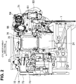
FIG. 2] FIG. 2 is a front view of an engine. - [
FIG. 3] FIG. 3 is a cross-sectional view of an intake system of the engine. - [
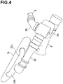
FIG. 4] FIG. 4 is a perspective view of the intake system of the engine. - [
FIG. 5] FIG. 5 is a front view of the intake system of the engine. - [
FIG. 6] FIG. 6 is a cross-sectional view of a connection portion between a bypass passage and an EGR passage. - [
FIG. 7] FIG. 7 is a side view illustrating flows of fresh air and EGR gas. - [
FIG. 8] FIG. 8 is a diagram illustrating an EGR concentration distribution in each portion in the bypass passage. - A form for carrying out the present invention will hereinafter be described based on drawings. The description of a preferable embodiment is substantially only exemplification and is not intended to restrict the present invention, applications thereof, or uses thereof.
- In a vehicle-installed engine system illustrated in
FIG. 1 , a reference numeral 1 denotes an engine, areference numeral 2 denotes an intake passage of the engine 1, a reference numeral 3 denotes an exhaust passage of the engine 1, and areference numeral 4 denotes a fuel tank. The system includes an evaporated fuel treatment device 5 leading evaporated fuel produced in thefuel tank 4 to the intake passage of the engine 1. - The engine 1 is an in-line four-cylinder compression ignition engine.
FIG. 1 illustrates only one cylinder of the engine 1. The engine 1 described in this embodiment is merely one example, and in the present invention, types and specific configurations of an engine are not limited. The engine 1 includes a direct injectionfuel injection valve 11, aspark plug 12, and a cylinderinner pressure sensor 13, which face acombustion chamber 10 of each cylinder. In the engine 1, an intake valve 14 is provided to an intake port, and anexhaust valve 15 is provide to an exhaust port. The engine 1 includesvariable valve mechanisms 16 and 17 for respectively driving the intake valve 14 and theexhaust valve 15 to open and close. Areference numeral 18 denotes a piston of the engine 1. - The
intake passage 2 includes an intake manifold (not illustrated) for introducing intake air into thecombustion chambers 10 of the cylinders in a branched manner. In theintake passage 2, in order from an upstream side to a downstream side, anair cleaner 21, athrottle valve 22 adjusting an introduction amount of fresh air into thecombustion chambers 10, asupercharger 23 raising a pressure of gas introduced into thecombustion chambers 10, and anintercooler 24 cooling the gas introduced into thecombustion chambers 10 by a supercharger 3 are disposed. Further, in theintake passage 2, abypass passage 25 connecting an upstream side of thesupercharger 23 with a downstream side of theintercooler 24 is provided on a downstream side of thethrottle valve 22. - That is, the
intake passage 2 includes a supercharging passage in which thesupercharger 23 raising a pressure of the intake air introduced into thecombustion chambers 10 is arranged and thebypass passage 25 leading the intake air to thecombustion chambers 10 while bypassing thesupercharger 23. In thebypass passage 25, abypass valve 26 is provided which adjusts a flow amount of gas flowing through thebypass passage 25. - The
supercharger 23 of this embodiment is a mechanical supercharger driven via a belt by a crankshaft of the engine 1. A supercharger 44 of a mechanical type may be of a Roots type, a Lysholm type, a vane type, or a centrifugal type, for example. Note that instead of a mechanical supercharger, an electric supercharger or a turbosupercharger driven by exhaust energy may be employed. - The
supercharger 23 is connected with the crankshaft of the engine 1 via anelectromagnetic clutch 27. Transmission and disconnection of motive power from the engine 1 to thesupercharger 23 are performed by connection and disconnection of theelectromagnetic clutch 27. - When the
electromagnetic clutch 27 is set to a disconnected state (when thesupercharger 23 is not acting), thebypass valve 26 is fully opened. Accordingly, the intake air is introduced into thecombustion chambers 10 of the engine 1 by thebypass passage 25 without going through thesupercharger 23. That is, the engine 1 is operated in a naturally aspirated (non-supercharging) state. - When the
electromagnetic clutch 27 is set to a connected state (when thesupercharger 23 is acting), a supercharging pressure is adjusted to a desired pressure by control of thebypass valve 26. That is, when thebypass valve 26 is opened, a portion of the intake air passing through thesupercharger 23 goes through thebypass passage 25 and reversely flows to an upstream side of thesupercharger 23. Because a reverse flow amount of the intake air changes in accordance with the opening of thebypass valve 26, the supercharging pressure of the intake air introduced into thecombustion chambers 10 can be controlled. - The exhaust passage 3 includes an
exhaust manifold 31 for gathering and discharging exhaust gas of the cylinders. In the exhaust passage 3 on a downstream side of theexhaust manifold 31, two catalytic converters purifying the exhaust gas are provided. The catalytic converter on an upstream side has a three-way catalyst 32 and a GPF (gasoline particulate filter) 33 and is disposed in an engine room of a vehicle. The catalytic converter on a downstream side has a three-way catalyst 34 and is disposed on the outside of the engine room. Anexhaust shutter valve 35 is provided to each branch pipe of theexhaust manifold 31. - The
intake passage 2 and the exhaust passage 3 are connected together by anEGR passage 6 returning a portion of the exhaust gas as EGR gas to theintake passage 2. An upstream end of theEGR passage 6 is connected with a portion in the exhaust passage 3 between the upstream catalytic converter and the downstream catalytic converter. A downstream end of theEGR passage 6 is connected with an intermediate portion of thebypass passage 25 so as to supply the EGR gas to a portion in theintake passage 2 on a downstream side of thethrottle valve 22 and on an upstream side of thesupercharger 23. The EGR gas enters an upstream side of thesupercharger 23 in theintake passage 2 without going through thebypass valve 26 of thebypass passage 25. In theEGR passage 6, anEGR cooler 61 cooling the EGR gas and anEGR valve 62 adjusting a returning amount of the EGR gas are disposed. - Note that although
FIG. 1 depicts theEGR valve 62 as provided in an intermediate portion of theEGR passage 6, in this embodiment, theEGR valve 62 is provided to a connection port of theEGR passage 6 to thebypass passage 25. - The
fuel tank 4 is connected with thefuel injection valves 11 by a fuel supply passage 41. An upstream end of the fuel supply passage 41 is connected with afuel strainer 40 in thefuel tank 4. In the fuel supply passage 41, afuel pump 42 and acommon rail 43 are provided. Thefuel pump 42 pumps fuel into thecommon rail 43. Thecommon rail 43 stores the fuel pumped from thefuel pump 42 at a high fuel pressure. When thefuel injection valve 11 is opened, the fuel stored in thecommon rail 43 is injected from an injection hole of thefuel injection valve 11 into thecombustion chamber 10. - The evaporated fuel treatment device 5 includes canisters 51 causing the evaporated fuel produced in the
fuel tank 4 to be adsorbed onto activated carbon. Thefuel tank 4 and the canisters 51 are connected together by a tank-side passage 52, and the canisters 51 and theintake passage 2 are connected together by apurge passage 53. An outsideair introduction passage 54 having an atmospheric opening is connected with the canisters 51. Apurge valve 55 opening and closing thepurge passage 53 is provided to thepurge passage 53. Thepurge valve 55 opens when a predetermined purge condition is satisfied, for example, in a state where an air-fuel ratio of the engine 1 can properly be controlled by control of a fuel injection amount by thefuel injection valves 11. - When a negative pressure is generated on a downstream side of the
throttle valve 22 in theintake passage 2 in a state where thepurge valve 55 is open, the evaporated fuel collected in the canisters 51 is purged. That is, together with air introduced from the outsideair introduction passage 54 into the canisters 51, the evaporated fuel is purged from thepurge passage 53 to a downstream side of thethrottle valve 22 in anintake passage 21. The purged evaporated fuel is supplied to thecombustion chambers 10 of theengine 10 through thesupercharger 23 or thebypass passage 25 and is combusted together with the fuel supplied from thefuel injection valves 11. - The engine system includes a blowby gas returning device. The blowby gas returning device includes a
blowby passage 57 and anair introduction passage 58. One end of theblowby passage 57 is connected with acrankcase 1a of the engine 1, and the other end is connected with a portion of theintake passage 2 on a downstream side of thethrottle valve 22 and on an upstream side of thesupercharger 23. A PCV (positive crankcase ventilation)valve 59 is provided to theblowby passage 57. - The
PCV valve 59 allows only gas in a direction from thecrankcase 1a side to theintake passage 2 side to pass through. In a negative pressure state where the pressure on the downstream side of thethrottle valve 22 in theintake passage 2 is lower than the pressure of thecrankcase 1a, the opening of thePCV valve 59 changes in accordance with the extent of the negative pressure. That is, a blowby gas flow amount from thecrankcase 1a to theintake passage 2 is adjusted to an appropriate amount in accordance with the negative pressure. - One end of the
air introduction passage 58 is connected with thecrankcase 1a via acylinder head 1b of the engine 1, and the other end is connected with a portion of theintake passage 2 between theair cleaner 21 and thethrottle valve 22. In theair introduction passage 58, acheck valve 60 is provided which allows only air in a direction from theintake passage 2 side to thecrankcase 1a side to pass through. - When blowby gas is released from the
crankcase 1a to theintake passage 2 through theblowby passage 57, air filtered by theair cleaner 21 is introduced from theair introduction passage 58 into thecrankcase 1a. Accordingly, thecrankcase 1a is ventilated. - In the
intake passage 2, anair flow sensor 63 detecting an intake air amount, apressure sensor 64 detecting an intake pressure on a downstream side of the throttle valve 22 (an upstream side of the supercharger 23), atemperature sensor 65 detecting the temperature of the intake air ejected from thesupercharger 23, and apressure sensor 66 detecting the intake pressure on a downstream side of theintercooler 24 are provided, the sensors being for controlling the engine 1. In the exhaust passage 3, a linear O2 sensor 67 detecting an oxygen concentration in the exhaust gas on an upstream side of the three-way catalyst 32 and a lambda O2 sensor 68 detecting the oxygen concentration in the exhaust gas on a downstream side of the three-way catalyst 32 are provided. - As illustrated in
FIG. 2 , thesupercharger 23 is provided in a state where an axis extends in a cylinder array direction in a portion above the engine 1. Anupstream intake pipe 71 configuring theintake passage 2 extending in the cylinder array direction is coupled with thissupercharger 23. Adrive part housing 72 of thesupercharger 23 protrudes toward the opposite side, in thesupercharger 23, to theupstream intake pipe 71. Theelectromagnetic clutch 27 and a driving shaft for driving thesupercharger 23 by the crankshaft of the engine 1 are housed in thisdrive part housing 72. Atransmission belt 74 is wound around apulley 73 coupled with the driving shaft. - An upstream end of an
ejection duct 76 for leading pressurized intake air to a surge tank (reference sign 75 inFIG. 4 ) extending in the cylinder array direction is connected with a side surface of thesupercharger 23. Theejection duct 76 extends to a lower side of thesupercharger 23, and a lower end thereof is connected with theintercooler 24 arranged below thesupercharger 23. - As illustrated in
FIG. 3 , athrottle body 77 including thethrottle valve 22 is provided to an upstream end portion of theupstream intake pipe 71. Thethrottle valve 22 is a butterfly valve, and avalve shaft 22a thereof is horizontally provided. On a downstream side of the throttle body 77 (an upstream side of the supercharger 23), abypass pipe 78 forming thebypass passage 25 obliquely rises from an upper surface of theupstream intake pipe 71 toward an upstream side of theupstream intake pipe 71. That is, on a downstream side of thethrottle valve 22, a connection port 79 of thebypass passage 25 opens in a top portion of an upper half circumferential portion of theintake passage 2 formed with theupstream intake pipe 71. - On a downstream side of the connection port 79 of the
bypass passage 25, theupstream intake pipe 71 forms apassage expanding portion 2b in which a passage cross-sectional area expands toward the supercharger 3, and an expanding end thereof is connected with the supercharger 3. - The
bypass pipe 78 has a foldedportion 78a that is continuous with the above-described oblique rising portion and is folded, in a curved manner, toward a downstream side of theupstream intake pipe 71. Thebypass pipe 78 is continuous with the foldedportion 78a and extends toward a central side of thesurge tank 75 in the cylinder array direction above thesupercharger 23. An EGR pipe (not illustrated inFIG. 3 ) forming theEGR passage 6 is connected with a downstream side of the foldedportion 78a in thebypass pipe 78, and theEGR valve 62 is provided to aconnection port 69 of theEGR passage 6 to thebypass passage 25. Theconnection port 69 opens in a side surface of thebypass passage 25. Thebypass pipe 78 branches to afirst branch pipe 78b extending in one direction of the cylinder array direction and asecond branch pipe 78c extending in the other direction of the cylinder array direction. - As illustrated in
FIG. 4 ,branch portions bypass passage 25 respectively formed with both of thebranch pipes surge tank 75. - As illustrated in
FIG. 3 , thebypass valve 26 is provided in thebypass pipe 78 on a downstream side of theEGR valve 62. That is, theconnection port 69 of theEGR passage 6 opens in thebypass passage 25 on an upstream side of thebypass valve 26. Thebypass valve 26 is a butterfly valve, and avalve shaft 26a thereof is horizontally provided. - As illustrated in
FIG. 5 , an intakeair introduction passage 80 is integrally provided to thesurge tank 75. The intakeair introduction passage 80 extends to a lower side of thesurge tank 75 and is connected with theintercooler 24. Further, as illustrated inFIG. 5 , anEGR pipe 81 extending from the exhaust passage 3 includes a risingportion 91 rising from a lower position than thebypass pipe 78 toward a side surface of thebypass pipe 78, an upper end portion of the risingportion 91 is connected with the side surface of thebypass pipe 78. - As illustrated in
FIG. 6 , the risingportion 91 of theEGR pipe 81 forms apassage portion 92 extending toward theconnection port 69 of theEGR passage 6 in thebypass passage 25 and in a direction intersecting with thebypass passage 25 and intersecting with a center line D of theconnection port 69. In a middle portion of this risingportion 91, a flexible portion (bellows portion) 93 is provided which absorbs displacement between an upstream portion and a downstream portion of the middle portion. The upper end portion of the risingportion 91 forms a direction-changingportion 94 in a position close to theconnection port 69, the direction-changingportion 94 being continuous with thepassage portion 92, changing a direction to the direction of the center line D of theconnection port 69, and reaching theconnection port 69. - An expanding
portion 95 in which a passage cross-sectional area expands compared to the passage portion 92 (a passage portion with a circular cross section on a downstream side of the flexible portion 84) is formed in the direction-changingportion 94. The expandingportion 95 includes adivergent portion 96 in which the passage cross-sectional area gradually expands from a downstream end of thepassage portion 92 toward theconnection port 69. The passage cross-sectional area of the expandingportion 95 is larger than the passage cross-sectional area of theconnection port 69. The direction-changingportion 94 includes a portion in which the passage cross-sectional area shrinks and which is continuous with the expandingportion 95 and reaches theconnection port 69, and avalve seat 97 of theEGR valve 62 opening and closing theconnection port 69 is formed in the shrinking portion. - The
EGR valve 62 is of a poppet type, avalve shaft 98 thereof passes through thebypass passage 25 and extends in the direction of the center line D of theconnection port 69. That is, thevalve shaft 98 crosses an inside of thebypass passage 25 in the direction of the center line D of theconnection port 69. Thevalve shaft 98 moves forward and backward by being driven by a solenoid-type EGRvalve drive part 85 illustrated inFIG. 2 , and theconnection port 69 opens by movement of theEGR valve 62 to the expandingportion 95 side. - Note that in
FIG. 2 , areference numeral 83 denotes a drive part of thethrottle valve 22, and areference numeral 84 denotes a drive part of thebypass valve 26. - In the above embodiment, in a case where the
supercharger 23 is not acting, the case being illustrated inFIG. 3 , the fresh air passing through thethrottle valve 22 of theintake passage 2 flows into thebypass passage 25 through the connection port 79. The fresh air goes through a portion, in which theEGR valve 62 is provided, and a portion, in which thebypass valve 26 is provided, of thebypass passage 25 and is introduced from thebranch portions FIG. 4 into thesurge tank 75. - As illustrated in
FIG. 6 , when theEGR valve 62 opens (a valve open state is indicated by the chain lines), the EGR gas is led upward through thepassage portion 92 of theEGR passage 6. The flow direction of the EGR gas is changed from an upward direction to a lateral direction in the direction-changingportion 94 and flows from a portion around theEGR valve 62 into thebypass passage 25 through theconnection port 69. - As described above, when the flow direction of the EGR gas changes in the direction-changing
portion 94, in related art, in accordance with an operation state of the engine, that is, in accordance with the flow speed of the EGR gas, unevenness occurs to a flow of the EGR gas in the direction-changingportion 94. For example, as the flow speed becomes higher, the EGR gas is more likely to flow unevenly along an upper half circumferential side of the direction-changingportion 94 and to flow from an upper side of theEGR valve 62 into thebypass passage 25 through theconnection port 69. In this case, because the EGR gas moves obliquely downward from the upper side of theEGR valve 62 toward theconnection port 69 and as a result flows into a lower half circumferential side of thebypass passage 25, as illustrated inFIG. 7 andFIG. 8 , the fresh air and the EGR gas are likely to flow in two separate layers in thebypass passage 25. - On the other hand, in the above embodiment, because the expanding
portion 95 of the passage cross-sectional area is formed in the direction-changingportion 94, the flow speed of the EGR gas flowing through thepassage portion 92 is lowered in the expandingportion 95. This lowering of the flow speed reduces unevenness of the EGR gas in the direction-changingportion 94, and the EGR gas flows from the portion around theEGR valve 62 into thebypass passage 25 while comparatively evenly going through theconnection port 69. As a result, in thebypass passage 25, the EGR gas is likely to contact with the flow of the fresh air from a lateral side, and the fresh air and the EGR gas are thus easily mixed together. - Furthermore, in the above embodiment, because an upstream side of the expanding
portion 95 is formed as thedivergent portion 96, when the EGR gas passes through thedivergent portion 96, the EGR gas is easily spread in the whole expanding portion while its flow speed is gradually lowered. Thus, this is advantageous to reduction of unevenness of the flow of the EGR gas. - Further, in the above embodiment, because the
valve shaft 98 of theEGR valve 62 crosses thebypass passage 25, the fresh air moving while bypassing thevalve shaft 98 collides with the EGR gas flowing along thevalve shaft 98, and the fresh air and the EGR gas are easily mixed together. In addition, because when the fresh air and the EGR gas pass through thebypass valve 26, the flows of those are disturbed by thebypass valve 26, mixing easily progresses. - As described above, unevenness of the flow of the EGR gas passing through the
connection port 69 is reduced, and mixing of the fresh air and the EGR gas in thebypass passage 25 easily progresses. As a result, non-uniformity of EGR amounts among cylinders is reduced, and an advantage in securing combustion stability of the engine is consequently obtained. - Note that the
EGR valve 62 of the above embodiment is of a poppet type; however, a butterfly type EGR valve can also reduce unevenness of the flow of the EGR gas passing through theconnection port 69 by providing an expanding portion as described above in the vicinity of the connection port on a downstream side of the EGR valve. -
- 1
- engine
- 2
- intake passage
- 3
- exhaust passage
- 6
- EGR passage
- 10
- combustion chamber
- 23
- supercharger
- 25
- bypass passage
- 26
- bypass valve
- 62
- EGR valve
- 69
- connection port
- 92
- passage portion
- 94
- direction-changing portion
- 95
- expanding portion
- 96
- divergent portion
- 98
- valve shaft
Claims (6)
- An air intake device for an engine, the air intake device comprising:an intake passage leading intake air to combustion chambers of a multi-cylinder engine;an exhaust passage discharging exhaust gas from the combustion chambers; andan EGR passage connecting the intake passage with the exhaust passage and returning a portion of the exhaust gas as EGR gas from the exhaust passage to the intake passage, the air intake device being characterized in thatthe EGR passage includes, in a position close to a connection port to the intake passage, an expanding portion in which a passage cross-sectional area expands and which lowers a flow speed of the EGR gas so as to reduce an uneven flow, in the connection port, of the EGR gas flowing into the intake passage.
- The air intake device for an engine according to claim 1, characterized in that
the EGR passage includes a passage portion extending toward the connection port and in a direction intersecting with the intake passage and intersecting with a center line of the connection port and a direction-changing portion being continuous with the passage portion, changing a direction to the direction of the center line of the connection port, and reaching the connection port, and
the expanding portion is provided in the direction-changing portion. - The air intake device for an engine according to claim 1 or 2, characterized in that
the intake passage includes a supercharging passage in which a supercharger raising a pressure of the intake air introduced into the combustion chambers is arranged and a bypass passage connecting an upstream side with a downstream side of the supercharger and leading the intake air to the combustion chambers while bypassing the supercharger, and
the EGR passage is connected with the bypass passage of the intake passage. - The air intake device for an engine according to claim 3, characterized by comprising
an EGR valve of a poppet type, the EGR valve being provided to the connection port and adjusting a returning amount of the EGR gas, wherein
a valve shaft of the EGR valve passes through the bypass passage. - The air intake device for an engine according to claim 3 or 4, characterized by comprising
a bypass valve of a butterfly type, the bypass valve being provided in the bypass passage and adjusting a supercharging pressure of the intake air by the supercharger, wherein
the connection port opens on an upstream side of the bypass valve in the bypass passage. - The air intake device for an engine according to any one of claims 1 to 5, characterized in that
the expanding portion includes a divergent portion in which a passage cross-sectional area gradually expands toward the connection port.
Applications Claiming Priority (2)
| Application Number | Priority Date | Filing Date | Title |
|---|---|---|---|
| JP2018138348A JP7172234B2 (en) | 2018-07-24 | 2018-07-24 | engine intake system |
| PCT/JP2019/025515 WO2020021952A1 (en) | 2018-07-24 | 2019-06-27 | Air intake device for engine |
Publications (3)
| Publication Number | Publication Date |
|---|---|
| EP3808966A1 true EP3808966A1 (en) | 2021-04-21 |
| EP3808966A4 EP3808966A4 (en) | 2021-04-21 |
| EP3808966B1 EP3808966B1 (en) | 2022-04-20 |
Family
ID=69182081
Family Applications (1)
| Application Number | Title | Priority Date | Filing Date |
|---|---|---|---|
| EP19840003.8A Active EP3808966B1 (en) | 2018-07-24 | 2019-06-27 | Air intake device for engine |
Country Status (5)
| Country | Link |
|---|---|
| US (1) | US11378041B2 (en) |
| EP (1) | EP3808966B1 (en) |
| JP (1) | JP7172234B2 (en) |
| CN (1) | CN112449665B (en) |
| WO (1) | WO2020021952A1 (en) |
Families Citing this family (2)
| Publication number | Priority date | Publication date | Assignee | Title |
|---|---|---|---|---|
| FR3069609B1 (en) * | 2017-07-26 | 2019-08-23 | Mmt ag | FLUID DOSING VALVE |
| JP2020012429A (en) * | 2018-07-19 | 2020-01-23 | マツダ株式会社 | Evaporative fuel processor for engine |
Family Cites Families (29)
| Publication number | Priority date | Publication date | Assignee | Title |
|---|---|---|---|---|
| JPS6119664U (en) * | 1984-07-10 | 1986-02-04 | トヨタ自動車株式会社 | Exhaust gas recirculation device for supercharged engines |
| US5333456A (en) * | 1992-10-01 | 1994-08-02 | Carter Automotive Company, Inc. | Engine exhaust gas recirculation control mechanism |
| US6138651A (en) * | 1997-05-30 | 2000-10-31 | Nissan Motor Co., Ltd. | Exhaust gas recirculation system for engine |
| JP2003322039A (en) | 2002-04-26 | 2003-11-14 | Suzuki Motor Corp | Air supply cooling control device for supercharged engine |
| FR2847946B1 (en) * | 2002-11-28 | 2006-06-23 | Renault Sa | PERFECTED EXHAUST GAS RECIRCULATION SYSTEM FOR INTERNAL COMBUSTION ENGINE OF MOTOR VEHICLE |
| US7568340B2 (en) * | 2006-05-24 | 2009-08-04 | Honeywell International, Inc. | Exhaust gas recirculation mixer |
| US7624722B2 (en) * | 2007-12-31 | 2009-12-01 | Cummins, Inc | Apparatus and system for efficiently recirculating an exhaust gas in a combustion engine |
| US8056339B2 (en) * | 2010-01-08 | 2011-11-15 | Ford Global Technologies, Llc | Warming intake air using EGR cooler in dual-throttle boosted engine system |
| JP2013060921A (en) * | 2011-09-14 | 2013-04-04 | Fuji Heavy Ind Ltd | Exhaust gas recirculation apparatus for engine |
| JP2013108479A (en) * | 2011-11-24 | 2013-06-06 | Fuji Heavy Ind Ltd | Diesel engine |
| JP6051881B2 (en) * | 2013-01-15 | 2016-12-27 | いすゞ自動車株式会社 | Internal combustion engine and EGR gas mixing device |
| US9382825B2 (en) * | 2013-04-25 | 2016-07-05 | Ford Global Technologies, Llc | System and method for gas purge control |
| CN105190008B (en) * | 2013-05-08 | 2018-07-13 | 丰田自动车株式会社 | Internal combustion engine with supercharger |
| US9435298B2 (en) * | 2013-07-09 | 2016-09-06 | GM Global Technology Operations LLC | Dedicated EGR engine with dynamic load control |
| JP6040128B2 (en) * | 2013-09-03 | 2016-12-07 | 本田技研工業株式会社 | EGR device |
| US9422877B2 (en) * | 2013-10-11 | 2016-08-23 | General Electric Company | System and method for control of exhaust gas recirculation (EGR) utilizing process temperatures |
| JP2015124755A (en) * | 2013-12-27 | 2015-07-06 | 大豊工業株式会社 | Gas mixing equipment |
| US9206752B2 (en) * | 2014-01-31 | 2015-12-08 | Achates Power, Inc. | Air handling system for an opposed-piston engine in which a supercharger provides boost during engine startup and drives EGR during normal engine operation |
| DE102014210508A1 (en) * | 2014-06-03 | 2015-12-03 | Bayerische Motoren Werke Aktiengesellschaft | Charged internal combustion engine |
| JP6447104B2 (en) * | 2014-12-24 | 2019-01-09 | 三菱自動車工業株式会社 | Intake manifold |
| CN204458107U (en) * | 2014-12-25 | 2015-07-08 | 潍柴动力股份有限公司 | The mixing arrangement of gas recirculation system |
| US10094337B2 (en) * | 2015-03-10 | 2018-10-09 | Fca Us Llc | Dual path cooled exhaust gas recirculation for turbocharged gasoline engines |
| FR3033597B1 (en) * | 2015-03-11 | 2018-09-07 | Renault S.A.S | TURBOCHARGER INPUT CONNECTOR WITH EGR GAS DIFFUSER |
| JP6582863B2 (en) * | 2015-10-20 | 2019-10-02 | アイシン精機株式会社 | Intake system of an internal combustion engine with a supercharger |
| US10247143B2 (en) * | 2016-03-10 | 2019-04-02 | Subaru Corporation | Exhaust gas recirculation apparatus |
| JP6232093B2 (en) * | 2016-03-10 | 2017-11-15 | 株式会社Subaru | Gas reflux device |
| JP2018025123A (en) * | 2016-08-09 | 2018-02-15 | アイシン精機株式会社 | Intake device |
| US11118546B2 (en) * | 2017-08-25 | 2021-09-14 | Mazda Motor Corporation | Engine intake system |
| CN107327337A (en) * | 2017-08-31 | 2017-11-07 | 如皋市明德包装有限公司 | A kind of diesel installation structure of environment-friendly energy-saving |
-
2018
- 2018-07-24 JP JP2018138348A patent/JP7172234B2/en active Active
-
2019
- 2019-06-27 WO PCT/JP2019/025515 patent/WO2020021952A1/en not_active Ceased
- 2019-06-27 US US17/261,551 patent/US11378041B2/en active Active
- 2019-06-27 EP EP19840003.8A patent/EP3808966B1/en active Active
- 2019-06-27 CN CN201980048170.8A patent/CN112449665B/en active Active
Also Published As
| Publication number | Publication date |
|---|---|
| EP3808966B1 (en) | 2022-04-20 |
| JP2020016164A (en) | 2020-01-30 |
| WO2020021952A1 (en) | 2020-01-30 |
| JP7172234B2 (en) | 2022-11-16 |
| US11378041B2 (en) | 2022-07-05 |
| CN112449665A (en) | 2021-03-05 |
| EP3808966A4 (en) | 2021-04-21 |
| US20210262420A1 (en) | 2021-08-26 |
| CN112449665B (en) | 2022-10-21 |
Similar Documents
| Publication | Publication Date | Title |
|---|---|---|
| US8056340B2 (en) | EGR mixer for high-boost engine systems | |
| US8499747B2 (en) | Method and device for operating an internal combustion engine | |
| US9771841B2 (en) | Crankcase ventilation for turbocharged engine | |
| US6886544B1 (en) | Exhaust gas venturi injector for an exhaust gas recirculation system | |
| US20110067395A1 (en) | Method of controlling an engine during transient operating conditions | |
| US20080216476A1 (en) | Turbocharged internal combustion engine with egr system having reverse flow | |
| US6230695B1 (en) | Exhaust gas recirculation system | |
| RU143271U1 (en) | TURBO COMPRESSOR SYSTEM WITH DOUBLE SNAIL | |
| GB2352272A (en) | Forced exhaust gas recirculation (EGR) system for i.c. engines | |
| US10718260B2 (en) | Exhaust gas purification apparatus for an internal combustion engine | |
| US8307646B2 (en) | System using supplemental compressor for EGR | |
| EP3808966B1 (en) | Air intake device for engine | |
| CN101326068A (en) | Internal combustion engine with turbocharger | |
| US11225918B2 (en) | Engine device | |
| US4364345A (en) | Split type internal combustion engine | |
| CN115427667B (en) | Improved reed valve and reed valve air box | |
| US11236706B2 (en) | Evaporated fuel treatment device for engine | |
| CN204003098U (en) | Flexible pipe and the system of aiming at for hose fixing holder | |
| JP4986168B2 (en) | Blow-by gas processing equipment | |
| JPH03281939A (en) | Engine provided with supercharger | |
| JP6613882B2 (en) | Engine control device | |
| JP2008075466A (en) | Exhaust system | |
| JPH0329570Y2 (en) | ||
| JPH04287860A (en) | Evaporated fuel control device for engine with supercharger |
Legal Events
| Date | Code | Title | Description |
|---|---|---|---|
| STAA | Information on the status of an ep patent application or granted ep patent |
Free format text: STATUS: THE INTERNATIONAL PUBLICATION HAS BEEN MADE |
|
| PUAI | Public reference made under article 153(3) epc to a published international application that has entered the european phase |
Free format text: ORIGINAL CODE: 0009012 |
|
| STAA | Information on the status of an ep patent application or granted ep patent |
Free format text: STATUS: REQUEST FOR EXAMINATION WAS MADE |
|
| 17P | Request for examination filed |
Effective date: 20210118 |
|
| A4 | Supplementary search report drawn up and despatched |
Effective date: 20210304 |
|
| AK | Designated contracting states |
Kind code of ref document: A1 Designated state(s): AL AT BE BG CH CY CZ DE DK EE ES FI FR GB GR HR HU IE IS IT LI LT LU LV MC MK MT NL NO PL PT RO RS SE SI SK SM TR |
|
| AX | Request for extension of the european patent |
Extension state: BA ME |
|
| DAV | Request for validation of the european patent (deleted) | ||
| DAX | Request for extension of the european patent (deleted) | ||
| RIC1 | Information provided on ipc code assigned before grant |
Ipc: F02B 37/16 20060101ALI20211005BHEP Ipc: F02M 26/21 20160101ALI20211005BHEP Ipc: F02M 26/04 20160101ALI20211005BHEP Ipc: F02M 26/70 20160101ALI20211005BHEP Ipc: F02M 26/44 20160101ALI20211005BHEP Ipc: F02M 26/39 20160101ALI20211005BHEP Ipc: F02M 26/67 20160101ALI20211005BHEP Ipc: F02M 26/03 20160101ALI20211005BHEP Ipc: F02B 33/00 20060101ALI20211005BHEP Ipc: F02M 26/19 20160101AFI20211005BHEP |
|
| GRAP | Despatch of communication of intention to grant a patent |
Free format text: ORIGINAL CODE: EPIDOSNIGR1 |
|
| STAA | Information on the status of an ep patent application or granted ep patent |
Free format text: STATUS: GRANT OF PATENT IS INTENDED |
|
| INTG | Intention to grant announced |
Effective date: 20211122 |
|
| RIN1 | Information on inventor provided before grant (corrected) |
Inventor name: ASHIKAGA, KENSUKE Inventor name: HIGASHIO, MASAYOSHI Inventor name: YANAGIDA, HARUNA Inventor name: YAMAMOTO, RYO Inventor name: TAKAMI, KENJI Inventor name: YOSHIDA, KEN Inventor name: WASADA, MITSUNORI Inventor name: YAMAUCHI, TAKETOSHI Inventor name: KATO, JIRO |
|
| GRAS | Grant fee paid |
Free format text: ORIGINAL CODE: EPIDOSNIGR3 |
|
| GRAA | (expected) grant |
Free format text: ORIGINAL CODE: 0009210 |
|
| STAA | Information on the status of an ep patent application or granted ep patent |
Free format text: STATUS: THE PATENT HAS BEEN GRANTED |
|
| AK | Designated contracting states |
Kind code of ref document: B1 Designated state(s): AL AT BE BG CH CY CZ DE DK EE ES FI FR GB GR HR HU IE IS IT LI LT LU LV MC MK MT NL NO PL PT RO RS SE SI SK SM TR |
|
| REG | Reference to a national code |
Ref country code: GB Ref legal event code: FG4D |
|
| REG | Reference to a national code |
Ref country code: CH Ref legal event code: EP |
|
| REG | Reference to a national code |
Ref country code: DE Ref legal event code: R096 Ref document number: 602019013975 Country of ref document: DE |
|
| REG | Reference to a national code |
Ref country code: IE Ref legal event code: FG4D |
|
| REG | Reference to a national code |
Ref country code: AT Ref legal event code: REF Ref document number: 1485328 Country of ref document: AT Kind code of ref document: T Effective date: 20220515 |
|
| REG | Reference to a national code |
Ref country code: LT Ref legal event code: MG9D |
|
| REG | Reference to a national code |
Ref country code: NL Ref legal event code: MP Effective date: 20220420 |
|
| REG | Reference to a national code |
Ref country code: AT Ref legal event code: MK05 Ref document number: 1485328 Country of ref document: AT Kind code of ref document: T Effective date: 20220420 |
|
| PG25 | Lapsed in a contracting state [announced via postgrant information from national office to epo] |
Ref country code: NL Free format text: LAPSE BECAUSE OF FAILURE TO SUBMIT A TRANSLATION OF THE DESCRIPTION OR TO PAY THE FEE WITHIN THE PRESCRIBED TIME-LIMIT Effective date: 20220420 |
|
| PG25 | Lapsed in a contracting state [announced via postgrant information from national office to epo] |
Ref country code: SE Free format text: LAPSE BECAUSE OF FAILURE TO SUBMIT A TRANSLATION OF THE DESCRIPTION OR TO PAY THE FEE WITHIN THE PRESCRIBED TIME-LIMIT Effective date: 20220420 Ref country code: PT Free format text: LAPSE BECAUSE OF FAILURE TO SUBMIT A TRANSLATION OF THE DESCRIPTION OR TO PAY THE FEE WITHIN THE PRESCRIBED TIME-LIMIT Effective date: 20220822 Ref country code: NO Free format text: LAPSE BECAUSE OF FAILURE TO SUBMIT A TRANSLATION OF THE DESCRIPTION OR TO PAY THE FEE WITHIN THE PRESCRIBED TIME-LIMIT Effective date: 20220720 Ref country code: LT Free format text: LAPSE BECAUSE OF FAILURE TO SUBMIT A TRANSLATION OF THE DESCRIPTION OR TO PAY THE FEE WITHIN THE PRESCRIBED TIME-LIMIT Effective date: 20220420 Ref country code: HR Free format text: LAPSE BECAUSE OF FAILURE TO SUBMIT A TRANSLATION OF THE DESCRIPTION OR TO PAY THE FEE WITHIN THE PRESCRIBED TIME-LIMIT Effective date: 20220420 Ref country code: GR Free format text: LAPSE BECAUSE OF FAILURE TO SUBMIT A TRANSLATION OF THE DESCRIPTION OR TO PAY THE FEE WITHIN THE PRESCRIBED TIME-LIMIT Effective date: 20220721 Ref country code: FI Free format text: LAPSE BECAUSE OF FAILURE TO SUBMIT A TRANSLATION OF THE DESCRIPTION OR TO PAY THE FEE WITHIN THE PRESCRIBED TIME-LIMIT Effective date: 20220420 Ref country code: ES Free format text: LAPSE BECAUSE OF FAILURE TO SUBMIT A TRANSLATION OF THE DESCRIPTION OR TO PAY THE FEE WITHIN THE PRESCRIBED TIME-LIMIT Effective date: 20220420 Ref country code: BG Free format text: LAPSE BECAUSE OF FAILURE TO SUBMIT A TRANSLATION OF THE DESCRIPTION OR TO PAY THE FEE WITHIN THE PRESCRIBED TIME-LIMIT Effective date: 20220720 Ref country code: AT Free format text: LAPSE BECAUSE OF FAILURE TO SUBMIT A TRANSLATION OF THE DESCRIPTION OR TO PAY THE FEE WITHIN THE PRESCRIBED TIME-LIMIT Effective date: 20220420 |
|
| PG25 | Lapsed in a contracting state [announced via postgrant information from national office to epo] |
Ref country code: RS Free format text: LAPSE BECAUSE OF FAILURE TO SUBMIT A TRANSLATION OF THE DESCRIPTION OR TO PAY THE FEE WITHIN THE PRESCRIBED TIME-LIMIT Effective date: 20220420 Ref country code: PL Free format text: LAPSE BECAUSE OF FAILURE TO SUBMIT A TRANSLATION OF THE DESCRIPTION OR TO PAY THE FEE WITHIN THE PRESCRIBED TIME-LIMIT Effective date: 20220420 Ref country code: LV Free format text: LAPSE BECAUSE OF FAILURE TO SUBMIT A TRANSLATION OF THE DESCRIPTION OR TO PAY THE FEE WITHIN THE PRESCRIBED TIME-LIMIT Effective date: 20220420 Ref country code: IS Free format text: LAPSE BECAUSE OF FAILURE TO SUBMIT A TRANSLATION OF THE DESCRIPTION OR TO PAY THE FEE WITHIN THE PRESCRIBED TIME-LIMIT Effective date: 20220820 |
|
| REG | Reference to a national code |
Ref country code: DE Ref legal event code: R097 Ref document number: 602019013975 Country of ref document: DE |
|
| PG25 | Lapsed in a contracting state [announced via postgrant information from national office to epo] |
Ref country code: SM Free format text: LAPSE BECAUSE OF FAILURE TO SUBMIT A TRANSLATION OF THE DESCRIPTION OR TO PAY THE FEE WITHIN THE PRESCRIBED TIME-LIMIT Effective date: 20220420 Ref country code: SK Free format text: LAPSE BECAUSE OF FAILURE TO SUBMIT A TRANSLATION OF THE DESCRIPTION OR TO PAY THE FEE WITHIN THE PRESCRIBED TIME-LIMIT Effective date: 20220420 Ref country code: RO Free format text: LAPSE BECAUSE OF FAILURE TO SUBMIT A TRANSLATION OF THE DESCRIPTION OR TO PAY THE FEE WITHIN THE PRESCRIBED TIME-LIMIT Effective date: 20220420 Ref country code: MC Free format text: LAPSE BECAUSE OF FAILURE TO SUBMIT A TRANSLATION OF THE DESCRIPTION OR TO PAY THE FEE WITHIN THE PRESCRIBED TIME-LIMIT Effective date: 20220420 Ref country code: EE Free format text: LAPSE BECAUSE OF FAILURE TO SUBMIT A TRANSLATION OF THE DESCRIPTION OR TO PAY THE FEE WITHIN THE PRESCRIBED TIME-LIMIT Effective date: 20220420 Ref country code: DK Free format text: LAPSE BECAUSE OF FAILURE TO SUBMIT A TRANSLATION OF THE DESCRIPTION OR TO PAY THE FEE WITHIN THE PRESCRIBED TIME-LIMIT Effective date: 20220420 Ref country code: CZ Free format text: LAPSE BECAUSE OF FAILURE TO SUBMIT A TRANSLATION OF THE DESCRIPTION OR TO PAY THE FEE WITHIN THE PRESCRIBED TIME-LIMIT Effective date: 20220420 |
|
| REG | Reference to a national code |
Ref country code: CH Ref legal event code: PL |
|
| REG | Reference to a national code |
Ref country code: BE Ref legal event code: MM Effective date: 20220630 |
|
| PLBE | No opposition filed within time limit |
Free format text: ORIGINAL CODE: 0009261 |
|
| STAA | Information on the status of an ep patent application or granted ep patent |
Free format text: STATUS: NO OPPOSITION FILED WITHIN TIME LIMIT |
|
| 26N | No opposition filed |
Effective date: 20230123 |
|
| PG25 | Lapsed in a contracting state [announced via postgrant information from national office to epo] |
Ref country code: AL Free format text: LAPSE BECAUSE OF FAILURE TO SUBMIT A TRANSLATION OF THE DESCRIPTION OR TO PAY THE FEE WITHIN THE PRESCRIBED TIME-LIMIT Effective date: 20220420 |
|
| PG25 | Lapsed in a contracting state [announced via postgrant information from national office to epo] |
Ref country code: LU Free format text: LAPSE BECAUSE OF NON-PAYMENT OF DUE FEES Effective date: 20220627 Ref country code: LI Free format text: LAPSE BECAUSE OF NON-PAYMENT OF DUE FEES Effective date: 20220630 Ref country code: IE Free format text: LAPSE BECAUSE OF NON-PAYMENT OF DUE FEES Effective date: 20220627 Ref country code: FR Free format text: LAPSE BECAUSE OF NON-PAYMENT OF DUE FEES Effective date: 20220630 Ref country code: CH Free format text: LAPSE BECAUSE OF NON-PAYMENT OF DUE FEES Effective date: 20220630 |
|
| PG25 | Lapsed in a contracting state [announced via postgrant information from national office to epo] |
Ref country code: SI Free format text: LAPSE BECAUSE OF FAILURE TO SUBMIT A TRANSLATION OF THE DESCRIPTION OR TO PAY THE FEE WITHIN THE PRESCRIBED TIME-LIMIT Effective date: 20220420 Ref country code: BE Free format text: LAPSE BECAUSE OF NON-PAYMENT OF DUE FEES Effective date: 20220630 |
|
| PG25 | Lapsed in a contracting state [announced via postgrant information from national office to epo] |
Ref country code: IT Free format text: LAPSE BECAUSE OF FAILURE TO SUBMIT A TRANSLATION OF THE DESCRIPTION OR TO PAY THE FEE WITHIN THE PRESCRIBED TIME-LIMIT Effective date: 20220420 |
|
| GBPC | Gb: european patent ceased through non-payment of renewal fee |
Effective date: 20230627 |
|
| PG25 | Lapsed in a contracting state [announced via postgrant information from national office to epo] |
Ref country code: MK Free format text: LAPSE BECAUSE OF FAILURE TO SUBMIT A TRANSLATION OF THE DESCRIPTION OR TO PAY THE FEE WITHIN THE PRESCRIBED TIME-LIMIT Effective date: 20220420 Ref country code: CY Free format text: LAPSE BECAUSE OF FAILURE TO SUBMIT A TRANSLATION OF THE DESCRIPTION OR TO PAY THE FEE WITHIN THE PRESCRIBED TIME-LIMIT Effective date: 20220420 Ref country code: GB Free format text: LAPSE BECAUSE OF NON-PAYMENT OF DUE FEES Effective date: 20230627 |
|
| PG25 | Lapsed in a contracting state [announced via postgrant information from national office to epo] |
Ref country code: HU Free format text: LAPSE BECAUSE OF FAILURE TO SUBMIT A TRANSLATION OF THE DESCRIPTION OR TO PAY THE FEE WITHIN THE PRESCRIBED TIME-LIMIT; INVALID AB INITIO Effective date: 20190627 |
|
| PG25 | Lapsed in a contracting state [announced via postgrant information from national office to epo] |
Ref country code: TR Free format text: LAPSE BECAUSE OF FAILURE TO SUBMIT A TRANSLATION OF THE DESCRIPTION OR TO PAY THE FEE WITHIN THE PRESCRIBED TIME-LIMIT Effective date: 20220420 |
|
| PG25 | Lapsed in a contracting state [announced via postgrant information from national office to epo] |
Ref country code: MT Free format text: LAPSE BECAUSE OF FAILURE TO SUBMIT A TRANSLATION OF THE DESCRIPTION OR TO PAY THE FEE WITHIN THE PRESCRIBED TIME-LIMIT Effective date: 20220420 |
|
| PG25 | Lapsed in a contracting state [announced via postgrant information from national office to epo] |
Ref country code: BG Free format text: LAPSE BECAUSE OF FAILURE TO SUBMIT A TRANSLATION OF THE DESCRIPTION OR TO PAY THE FEE WITHIN THE PRESCRIBED TIME-LIMIT Effective date: 20220420 |
|
| PG25 | Lapsed in a contracting state [announced via postgrant information from national office to epo] |
Ref country code: BG Free format text: LAPSE BECAUSE OF FAILURE TO SUBMIT A TRANSLATION OF THE DESCRIPTION OR TO PAY THE FEE WITHIN THE PRESCRIBED TIME-LIMIT Effective date: 20220420 |
|
| PGFP | Annual fee paid to national office [announced via postgrant information from national office to epo] |
Ref country code: DE Payment date: 20250429 Year of fee payment: 7 |