EP3808936A1 - Method of servicing a gas turbine engine or components - Google Patents
Method of servicing a gas turbine engine or components Download PDFInfo
- Publication number
- EP3808936A1 EP3808936A1 EP20202145.7A EP20202145A EP3808936A1 EP 3808936 A1 EP3808936 A1 EP 3808936A1 EP 20202145 A EP20202145 A EP 20202145A EP 3808936 A1 EP3808936 A1 EP 3808936A1
- Authority
- EP
- European Patent Office
- Prior art keywords
- gas turbine
- component
- turbine engine
- titanium alloy
- heat treatment
- Prior art date
- Legal status (The legal status is an assumption and is not a legal conclusion. Google has not performed a legal analysis and makes no representation as to the accuracy of the status listed.)
- Granted
Links
Images

Classifications
-
- F—MECHANICAL ENGINEERING; LIGHTING; HEATING; WEAPONS; BLASTING
- F01—MACHINES OR ENGINES IN GENERAL; ENGINE PLANTS IN GENERAL; STEAM ENGINES
- F01D—NON-POSITIVE DISPLACEMENT MACHINES OR ENGINES, e.g. STEAM TURBINES
- F01D5/00—Blades; Blade-carrying members; Heating, heat-insulating, cooling or antivibration means on the blades or the members
- F01D5/005—Repairing methods or devices
-
- B—PERFORMING OPERATIONS; TRANSPORTING
- B23—MACHINE TOOLS; METAL-WORKING NOT OTHERWISE PROVIDED FOR
- B23P—METAL-WORKING NOT OTHERWISE PROVIDED FOR; COMBINED OPERATIONS; UNIVERSAL MACHINE TOOLS
- B23P6/00—Restoring or reconditioning objects
- B23P6/002—Repairing turbine components, e.g. moving or stationary blades, rotors
-
- C—CHEMISTRY; METALLURGY
- C22—METALLURGY; FERROUS OR NON-FERROUS ALLOYS; TREATMENT OF ALLOYS OR NON-FERROUS METALS
- C22F—CHANGING THE PHYSICAL STRUCTURE OF NON-FERROUS METALS AND NON-FERROUS ALLOYS
- C22F1/00—Changing the physical structure of non-ferrous metals or alloys by heat treatment or by hot or cold working
- C22F1/16—Changing the physical structure of non-ferrous metals or alloys by heat treatment or by hot or cold working of other metals or alloys based thereon
- C22F1/18—High-melting or refractory metals or alloys based thereon
- C22F1/183—High-melting or refractory metals or alloys based thereon of titanium or alloys based thereon
-
- F—MECHANICAL ENGINEERING; LIGHTING; HEATING; WEAPONS; BLASTING
- F01—MACHINES OR ENGINES IN GENERAL; ENGINE PLANTS IN GENERAL; STEAM ENGINES
- F01D—NON-POSITIVE DISPLACEMENT MACHINES OR ENGINES, e.g. STEAM TURBINES
- F01D5/00—Blades; Blade-carrying members; Heating, heat-insulating, cooling or antivibration means on the blades or the members
- F01D5/34—Rotor-blade aggregates of unitary construction, e.g. formed of sheet laminae
-
- F—MECHANICAL ENGINEERING; LIGHTING; HEATING; WEAPONS; BLASTING
- F05—INDEXING SCHEMES RELATING TO ENGINES OR PUMPS IN VARIOUS SUBCLASSES OF CLASSES F01-F04
- F05D—INDEXING SCHEME FOR ASPECTS RELATING TO NON-POSITIVE-DISPLACEMENT MACHINES OR ENGINES, GAS-TURBINES OR JET-PROPULSION PLANTS
- F05D2220/00—Application
- F05D2220/30—Application in turbines
- F05D2220/32—Application in turbines in gas turbines
- F05D2220/323—Application in turbines in gas turbines for aircraft propulsion, e.g. jet engines
-
- F—MECHANICAL ENGINEERING; LIGHTING; HEATING; WEAPONS; BLASTING
- F05—INDEXING SCHEMES RELATING TO ENGINES OR PUMPS IN VARIOUS SUBCLASSES OF CLASSES F01-F04
- F05D—INDEXING SCHEME FOR ASPECTS RELATING TO NON-POSITIVE-DISPLACEMENT MACHINES OR ENGINES, GAS-TURBINES OR JET-PROPULSION PLANTS
- F05D2230/00—Manufacture
- F05D2230/40—Heat treatment
-
- F—MECHANICAL ENGINEERING; LIGHTING; HEATING; WEAPONS; BLASTING
- F05—INDEXING SCHEMES RELATING TO ENGINES OR PUMPS IN VARIOUS SUBCLASSES OF CLASSES F01-F04
- F05D—INDEXING SCHEME FOR ASPECTS RELATING TO NON-POSITIVE-DISPLACEMENT MACHINES OR ENGINES, GAS-TURBINES OR JET-PROPULSION PLANTS
- F05D2230/00—Manufacture
- F05D2230/72—Maintenance
-
- F—MECHANICAL ENGINEERING; LIGHTING; HEATING; WEAPONS; BLASTING
- F05—INDEXING SCHEMES RELATING TO ENGINES OR PUMPS IN VARIOUS SUBCLASSES OF CLASSES F01-F04
- F05D—INDEXING SCHEME FOR ASPECTS RELATING TO NON-POSITIVE-DISPLACEMENT MACHINES OR ENGINES, GAS-TURBINES OR JET-PROPULSION PLANTS
- F05D2230/00—Manufacture
- F05D2230/80—Repairing, retrofitting or upgrading methods
-
- F—MECHANICAL ENGINEERING; LIGHTING; HEATING; WEAPONS; BLASTING
- F05—INDEXING SCHEMES RELATING TO ENGINES OR PUMPS IN VARIOUS SUBCLASSES OF CLASSES F01-F04
- F05D—INDEXING SCHEME FOR ASPECTS RELATING TO NON-POSITIVE-DISPLACEMENT MACHINES OR ENGINES, GAS-TURBINES OR JET-PROPULSION PLANTS
- F05D2300/00—Materials; Properties thereof
- F05D2300/10—Metals, alloys or intermetallic compounds
- F05D2300/17—Alloys
- F05D2300/174—Titanium alloys, e.g. TiAl
-
- Y—GENERAL TAGGING OF NEW TECHNOLOGICAL DEVELOPMENTS; GENERAL TAGGING OF CROSS-SECTIONAL TECHNOLOGIES SPANNING OVER SEVERAL SECTIONS OF THE IPC; TECHNICAL SUBJECTS COVERED BY FORMER USPC CROSS-REFERENCE ART COLLECTIONS [XRACs] AND DIGESTS
- Y10—TECHNICAL SUBJECTS COVERED BY FORMER USPC
- Y10T—TECHNICAL SUBJECTS COVERED BY FORMER US CLASSIFICATION
- Y10T29/00—Metal working
- Y10T29/49—Method of mechanical manufacture
- Y10T29/49316—Impeller making
- Y10T29/49318—Repairing or disassembling
-
- Y—GENERAL TAGGING OF NEW TECHNOLOGICAL DEVELOPMENTS; GENERAL TAGGING OF CROSS-SECTIONAL TECHNOLOGIES SPANNING OVER SEVERAL SECTIONS OF THE IPC; TECHNICAL SUBJECTS COVERED BY FORMER USPC CROSS-REFERENCE ART COLLECTIONS [XRACs] AND DIGESTS
- Y10—TECHNICAL SUBJECTS COVERED BY FORMER USPC
- Y10T—TECHNICAL SUBJECTS COVERED BY FORMER US CLASSIFICATION
- Y10T29/00—Metal working
- Y10T29/49—Method of mechanical manufacture
- Y10T29/49718—Repairing
- Y10T29/49721—Repairing with disassembling
- Y10T29/49723—Repairing with disassembling including reconditioning of part
Definitions
- Exemplary embodiments of the present disclosure pertain to servicing of operational titanium alloy components in gas turbine engines, including gas turbine engines on aircraft.
- Modern gas turbine engines are subject to demanding operating conditions involving significant levels of force.
- Components of the gas turbine engines such as fan blade rotors can be subject to damage that can shorten operational life of the engine or the components thereof, or can require costly repair or remanufacture of the gas turbine engine or the components thereof.
- damage to the component(s) can result in catastrophic failure of the component(s) and accompanying failure of the engine and damage to the aircraft and risk to flight operations.
- Previous attempts to manage this risk have involved inspection of the gas turbine engine and the components thereof in the hopes of identifying damage such as cracks in metal alloys before they propagate to the point of causing failure of the component(s).
- inspection regimens may not identify all damage, or may identify damage after a point at which repair is possible, which can lead to costly replacement of the component(s).
- a method of servicing a gas turbine engine is disclosed. According to the method, a component comprising a titanium alloy is removed from the gas turbine engine after operating the gas turbine engine with the component in service. The removed component is subjected to heat treatment, and the heat-treated component is re-installed into the gas turbine engine or installed into a different gas turbine engine.
- the removing of the component from the gas turbine engine can be performed in response to predetermined criteria of operating the gas turbine engine.
- the predetermined criteria can include a cumulative time of operation of the gas turbine engine comprising said component.
- the predetermined criteria can include a cumulative number of operation cycles of the gas turbine engine comprising said component.
- the predetermined criteria can include a stress level applied to said component during operation of the gas turbine engine comprising said component.
- the heat treatment can be performed below a beta transus temperature of the titanium alloy.
- the component can be re-installed into the gas turbine engine or installed into a different gas turbine engine without mechanical repair of the component.
- the component can be selected from a rotor hub or a bladed rotor hub.
- the titanium alloy prior to the heat treatment can include dislocations between metal grains in the titanium alloy.
- the heat treatment annihilates the dislocations.
- the titanium alloy can include soft grains oriented for slip and hard grains not oriented for slip.
- the titanium alloy prior to the heat treatment can include dislocations between the soft grains and the hard grains, and the heat treatment annihilates said dislocations.
- the titanium alloy can include an alpha phase and a beta phase.
- the titanium alloy can be selected from Ti-6Al-4V, Ti-6Al-6V-2Sn, Ti-6Al-2Sn-4Zr-2Mo, Ti 834 (5.8Al-4Sn-3.5Zr-0.7Nb-0.5Mo-0.3Si-.08C), Ti-1100 (6Al-2.75Sn-4Zr-0.4Mo-0.45Si), Ti-811(8Al-1Mo-1V), Ti-685 (6A1-5Zr-0.5Mo-0.25Si), or Ti-17 (5Al-2Sn-2Zr-4Mo-4Cr).
- an aircraft includes an aircraft body 101, which can include one or more bays 103 beneath a center wing box.
- the bay 103 can contain and/or support one or more components of the aircraft 101.
- the aircraft includes one or more engines 111.
- the engines 111 are typically mounted on the wings 112 of the aircraft and are connected to fuel tanks (not shown) in the wings, but may be located at other locations depending on the specific aircraft configuration.
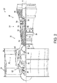
- FIG. 2 schematically illustrates a gas turbine engine 20.
- the gas turbine engine 20 is disclosed herein as a two-spool turbofan that generally incorporates a fan section 22, a compressor section 24, a combustor section 26 and a turbine section 28.
- Alternative engines might include other systems or features.
- the fan section 22 drives air along a bypass flow path B in a bypass duct, while the compressor section 24 drives air along a core flow path C for compression and communication into the combustor section 26 then expansion through the turbine section 28.
- FIG. 2 schematically illustrates a gas turbine engine 20.
- the gas turbine engine 20 is disclosed herein as a two-spool turbofan that generally incorporates a fan section 22, a compressor section 24, a combustor section 26 and a turbine section 28.
- Alternative engines might include other systems or features.
- the fan section 22 drives air along a bypass flow path B in a bypass duct
- the compressor section 24 drives air along a core flow path C for compression and communication into the combustor section 26
- the exemplary engine 20 generally includes a low speed spool 30 and a high speed spool 32 mounted for rotation about an engine central longitudinal axis. A relative to an engine static structure 36 via several bearing systems 38. It should be understood that various bearing systems 38 at various locations may alternatively or additionally be provided, and the location of bearing systems 38 may be varied as appropriate to the application.
- the low speed spool 30 generally includes an inner shaft 40 that interconnects a fan 42, a low pressure compressor 44 and a low pressure turbine 46.
- the inner shaft 40 is connected to the fan 42 through a speed change mechanism, which in exemplary gas turbine engine 20 is illustrated as a geared architecture 48 to drive the fan 42 at a lower speed than the low speed spool 30.
- the high speed spool 32 includes an outer shaft 50 that interconnects a high pressure compressor 52 and high pressure turbine 54.
- a combustor 56 is arranged in exemplary gas turbine 20 between the high pressure compressor 52 and the high pressure turbine 54.
- An engine static structure 36 is arranged generally between the high pressure turbine 54 and the low pressure turbine 46.
- the engine static structure 36 further supports bearing systems 38 in the turbine section 28.
- the inner shaft 40 and the outer shaft 50 are concentric and rotate via bearing systems 38 about the engine central longitudinal axis A which is collinear with their longitudinal axes.
- each of the positions of the fan section 22, compressor section 24, combustor section 26, turbine section 28, and fan drive gear system 48 may be varied.
- gear system 48 may be located aft of combustor section 26 or even aft of turbine section 28, and fan section 22 may be positioned forward or aft of the location of gear system 48.
- the engine 20 in one example is a high-bypass geared aircraft engine.
- the engine 20 bypass ratio is greater than about six (6), with an example embodiment being greater than about ten (10)
- the geared architecture 48 is an epicyclic gear train, such as a planetary gear system or other gear system, with a gear reduction ratio of greater than about 2.3 and the low pressure turbine 46 has a pressure ratio that is greater than about five.
- the engine 20 bypass ratio is greater than about ten (10:1)
- the fan diameter is significantly larger than that of the low pressure compressor 44
- the low pressure turbine 46 has a pressure ratio that is greater than about five (5:1).
- Low pressure turbine 46 pressure ratio is pressure measured prior to inlet of low pressure turbine 46 as related to the pressure at the outlet of the low pressure turbine 46 prior to an exhaust nozzle.
- the geared architecture 48 may be an epicyclic gear train, such as a planetary gear system or other gear system, with a gear reduction ratio of greater than about 2.3:1. It should be understood, however, that the above parameters are only exemplary of one embodiment of a geared architecture engine and that the present disclosure is applicable to other gas turbine engines including direct drive turbofans.
- the fan section 22 of the engine 20 is designed for a particular flight conditiontypically cruise at about 0.8 Mach (274 m/s) and about 35,000 feet (10,668 meters).
- "Low fan pressure ratio” is the pressure ratio across the fan blade alone, without a Fan Exit Guide Vane (“FEGV”) system.
- the low fan pressure ratio as disclosed herein according to one non-limiting embodiment is less than about 1.45.
- Low corrected fan tip speed is the actual fan tip speed in ft/sec divided by an industry standard temperature correction of [(Tram °R)/(518.7 °R)] 0.5 .
- the "Low corrected fan tip speed” as disclosed herein according to one non-limiting embodiment is less than about 1150 ft/second (350.5 m/sec).
- components of a gas turbine engine can be removed from service and subj ected to heat treatment.
- the operation of the gas turbine engine in service can be on an aircraft, as operation of a gas turbine engine on an aircraft can expose engine component(s) to conditions that subject the component(s) to cold dwell fatigue as described in further detail below.
- the components to be serviced according to this disclosure include gas turbine engine rotor components.
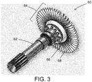
- An example embodiment of a gas turbine rotor 60 is schematically shown in FIG. 3 . As shown in FIG. 3 , the example embodiment of a gas turbine rotor 60 includes a shaft 62, a bladed hub or rim 64 that includes a hub or rim 66 and airfoil blades 68.
- an engine component such as the gas turbine rotor 60 can be disassembled into sub-assemblies such as the shaft 62 and the bladed hub or rim 64, followed by heat treatment of such sub-assemblies.
- the entire component e.g., the entire gas turbine rotor 60
- the entire component can be subject to heat treatment.
- only a portion of the engine component e.g., areas around a weld joint
- the component(s) to which heat treatment can be applied as disclosed herein can include various titanium alloys, including but not limited to multiphase titanium alloys such as alpha-beta titanium alloys, and single phase alloys such as alpha titanium alloys, or near-alpha titanium alloys.
- Examples of titanium alloys to which heat treatment can be applied include but are not limited to Ti-6Al-4V, Ti-6Al-6V-2Sn, Ti-6Al-2Sn-4Zr-2Mo.
- Ti 834 (5.8Al-4Sn-3.5Zr-0.7Nb-0.5Mo-0.3Si-.08C), Ti-1100 (6Al-2.75Sn-4Zr-0.4Mo-0.45Si), Ti-811(8Al-1Mo-1V), Ti-685 (6A1-5Zr-0.5Mo-0.25Si), or Ti-17 (5Al-2Sn-2Zr-4Mo-4Cr).
- the application of heat treatment can involve heating the component(s) to a temperature in a range having a low end of 600°F (320 °C), 800°F (430 °C), or 950°F (510 °C), and an upper end of 1100°F (590 °C), 1200°F (650 °C), or 1300°F (700 °C).
- the above range endpoints can be independently combined to produce a number of different ranges, and every possible range that can be formed by combination of the above endpoints is hereby expressly disclosed.
- the heat treatment is performed at a temperature that is below the beta transus temperature of the titanium alloy.
- a heat treatment temperature can be maintained for a duration in a range having a low end of 1 hour, 2 hours, or 3 hours, and an upper end of 6 hours, 7 hours, or 8 hours.
- the above range endpoints can be independently combined to produce a number of different ranges, and every possible range that can be formed by combination of the above endpoints is hereby expressly disclosed.
- the time and temperature are interrelated, with greater amounts of time generally required at lower temperatures and lower amounts of time required at higher temperatures. For example, 1-2 hours may be sufficient at temperatures of 1100°F-1300°F (590 °C - 700 °C).
- Heating can be provided by exposing the component(s) to a heat source such by placing the component(s) in a furnace or by other heating techniques such as conductive heating.
- the heat treatment temperature is generally provided at a level that should not have a significant impact to alter the basic grain morphology of the titanium alloy, so quenching protocol will generally not be critical for performance, and cooling of the alloy can be accomplished in whatever manner may be efficient for processing operations.
- cooling can be provided by deactivating whatever heat source was used for the heat treatment, or by removing the heat source or removing the component(s) from the presence of the heat source, and allowing the component(s) to cool naturally and/or by assisting with convective cooling such as contacting the components with moving air from an air source such as a fan.
- the heat treatment can be applied at service intervals for the gas turbine engine in which the component(s) are operated.
- Various criteria can be used to identify an interval for removal of the component(s) from the gas turbine engine and application of heat treatment.
- removal of the component(s) for application of heat treatment can be performed in response to predetermined criteria based on operation of the gas turbine engine.
- the predetermined criteria can include a cumulative time of operation of the gas turbine engine.
- an interval based on a cumulative time of operation can be a regular fixed interval or can be a variable interval that can be based on other variables including but not limited to total lifetime hours of operation of the engine in service (e.g., longer intervals earlier in the life of the engine and shorter intervals later in the life of the engine), number of engine operating cycles (e.g., with a greater number of cycles prompting a shorter interval), and/or operating conditions such as speed or temperature as further described below.
- the predetermined criteria can include a number of engine operating cycles (e.g., a startup to shutdown cycle).
- a predetermined criteria based on operating cycles can be in a range having a lower end of 200 cycles, 300 cycles, or 400 cycles, and an upper end of 2000 cycles, 3000 cycles, or 4000 cycles.
- the above range endpoints can be independently combined to produce a number of different ranges, and every possible range that can be formed by combination of the above endpoints is hereby expressly disclosed.
- the predetermined criteria can include a stress and/or a temperature to which the component(s) are exposed during engine operation. Stress can be assessed indirectly, such as by monitoring engine speed or torque, both of which can be directly related to a level of stress on the engine components.
- the heat treatment can alleviate accumulated strain that may be influenced by speed or torque and/or temperature to which the components are subjected during engine operation.
- Any one or more of the above examples of predetermined criteria can be used by themselves or can be combined to identify a point at which the component(s) should be removed from operational service for application of heat treatment.
- a prospective interval based on a cumulative number of hours of engine operation can be adjusted upward or downward based on whether the accumulated hours of engine operation or number of operating cycles occurred at engine speeds or torque and/or temperatures that were more or less likely to promote accumulation of strain in the titanium alloy.
- Data on any of the above criteria can be collected by a controller including a microprocessor operatively connected to sensors that can monitor the specified criteria.
- the microprocessor can be programmed with instructions for an algorithm that calculates an interval based on a variety of criteria, such as an algorithm in which points are accumulated based on operating conditions that can promote accumulation of strain, with higher point values applied to conditions that promote more strain accumulation (e.g., higher applied stress) and lower point values applied to conditions that promote less stress accumulation (e.g., lower applied stress). For example, an hour of operation at a low speed or torque may accumulate a specified point value whereas an hour of operation at a higher speed or torque may accumulate a higher point value, with heat treatment applied when accumulated points reach a predetermined threshold.
- an algorithm in which points are accumulated based on operating conditions that can promote accumulation of strain, with higher point values applied to conditions that promote more strain accumulation (e.g., higher applied stress) and lower point values applied to conditions that promote less stress accumulation (e.g., lower applied stress). For example, an hour of operation at a low speed or torque may accumulate a specified point value whereas an hour of operation at a higher speed or torque may accumulate a
- heat treatment can provide a technical effect of promoting annihilation of dislocations between grains in a titanium alloy's microstructure.
- dislocations can form when a titanium alloy component is subjected to prolonged and/or cycled periods of stress at temperatures less than about 400°F (200 °C), leading to a phenomenon of cold dwell fatigue. Unchecked, these dislocations can glide through soft grains in the alloy that are oriented for slip and unload stress onto hard grains that are not oriented for slip.
- Hard grains can be characterized as grains where the c-axis of the HCP (hexagonal close packed) crystal is oriented 0° to 25° with respect to the stress axis, and soft grains can be characterized as grains where the c-axis of the HCP crystal is oriented 70° to 90° with respect to the stress axis. Accumulation of dislocations at the hard grains can result in localized fields of high stress between the anisotropic distributions of soft and hard grains, resulting in reduced fatigue tolerance and ultimately the formation of cracks that can propagate to the point of a catastrophic failure of the component.
- Such dislocations can form in titanium alloys including single-phase grain structures such as alpha or near-alpha grain structures, but also in multiphase titanium alloy grain structures such as two-phase alpha-beta grain structures that can be especially susceptible to this phenomenon at least in part because slip can cross boundaries between phases and also because the multiple phases can provide additional grain boundaries along which dislocations can accumulate.
Landscapes
- Engineering & Computer Science (AREA)
- Mechanical Engineering (AREA)
- Chemical & Material Sciences (AREA)
- General Engineering & Computer Science (AREA)
- Physics & Mathematics (AREA)
- Thermal Sciences (AREA)
- Crystallography & Structural Chemistry (AREA)
- Materials Engineering (AREA)
- Metallurgy (AREA)
- Organic Chemistry (AREA)
- Ceramic Engineering (AREA)
- Structures Of Non-Positive Displacement Pumps (AREA)
Abstract
Description
- Exemplary embodiments of the present disclosure pertain to servicing of operational titanium alloy components in gas turbine engines, including gas turbine engines on aircraft.
- Modern gas turbine engines are subject to demanding operating conditions involving significant levels of force. Components of the gas turbine engines such as fan blade rotors can be subject to damage that can shorten operational life of the engine or the components thereof, or can require costly repair or remanufacture of the gas turbine engine or the components thereof. In some cases, damage to the component(s) can result in catastrophic failure of the component(s) and accompanying failure of the engine and damage to the aircraft and risk to flight operations. Previous attempts to manage this risk have involved inspection of the gas turbine engine and the components thereof in the hopes of identifying damage such as cracks in metal alloys before they propagate to the point of causing failure of the component(s). However, such inspection regimens may not identify all damage, or may identify damage after a point at which repair is possible, which can lead to costly replacement of the component(s).
- A method of servicing a gas turbine engine is disclosed. According to the method, a component comprising a titanium alloy is removed from the gas turbine engine after operating the gas turbine engine with the component in service. The removed component is subjected to heat treatment, and the heat-treated component is re-installed into the gas turbine engine or installed into a different gas turbine engine.
- In addition to one or more of the features described above, or as an alternative to any of the foregoing embodiments, the removing of the component from the gas turbine engine can be performed in response to predetermined criteria of operating the gas turbine engine.
- In addition to one or more of the features described above, or as an alternative to any of the foregoing embodiments, the predetermined criteria can include a cumulative time of operation of the gas turbine engine comprising said component.
- In addition to one or more of the features described above, or as an alternative to any of the foregoing embodiments, the predetermined criteria can include a cumulative number of operation cycles of the gas turbine engine comprising said component.
- In addition to one or more of the features described above, or as an alternative to any of the foregoing embodiments, the predetermined criteria can include a stress level applied to said component during operation of the gas turbine engine comprising said component.
- In addition to one or more of the features described above, or as an alternative to any of the foregoing embodiments, the heat treatment can be performed below a beta transus temperature of the titanium alloy.
- In addition to one or more of the features described above, or as an alternative to any of the foregoing embodiments, the component can be re-installed into the gas turbine engine or installed into a different gas turbine engine without mechanical repair of the component.
- In addition to one or more of the features described above, or as an alternative to any of the foregoing embodiments, the component can be selected from a rotor hub or a bladed rotor hub.
- In addition to one or more of the features described above, or as an alternative to any of the foregoing embodiments, prior to the heat treatment the titanium alloy can include dislocations between metal grains in the titanium alloy.
- In addition to one or more of the features described above, or as an alternative to any of the foregoing embodiments, the heat treatment annihilates the dislocations.
- In addition to one or more of the features described above, or as an alternative to any of the foregoing embodiments, the titanium alloy can include soft grains oriented for slip and hard grains not oriented for slip.
- In addition to one or more of the features described above, or as an alternative to any of the foregoing embodiments, prior to the heat treatment the titanium alloy can include dislocations between the soft grains and the hard grains, and the heat treatment annihilates said dislocations.
- In addition to one or more of the features described above, or as an alternative to any of the foregoing embodiments, the titanium alloy can include an alpha phase and a beta phase.
- In addition to one or more of the features described above, or as an alternative to any of the foregoing embodiments, the titanium alloy can be selected from Ti-6Al-4V, Ti-6Al-6V-2Sn, Ti-6Al-2Sn-4Zr-2Mo, Ti 834 (5.8Al-4Sn-3.5Zr-0.7Nb-0.5Mo-0.3Si-.08C), Ti-1100 (6Al-2.75Sn-4Zr-0.4Mo-0.45Si), Ti-811(8Al-1Mo-1V), Ti-685 (6A1-5Zr-0.5Mo-0.25Si), or Ti-17 (5Al-2Sn-2Zr-4Mo-4Cr).
- The following descriptions should not be considered limiting in any way. With reference to the accompanying drawings, like elements are numbered alike:
-
FIG. 1 is a schematic illustration of an aircraft that can incorporate various embodiments of the present disclosure; -
FIG. 2 is a partial cross-sectional view of a gas turbine engine; and -
FIG. 3 is a perspective view of a gas turbine engine rotor. - A detailed description of one or more embodiments of the disclosed apparatus and method are presented herein by way of exemplification and not limitation with reference to the Figures.
- As shown in
FIG. 1 , an aircraft includes anaircraft body 101, which can include one ormore bays 103 beneath a center wing box. Thebay 103 can contain and/or support one or more components of theaircraft 101. Also shown inFIG. 1 , the aircraft includes one ormore engines 111. Theengines 111 are typically mounted on the wings 112 of the aircraft and are connected to fuel tanks (not shown) in the wings, but may be located at other locations depending on the specific aircraft configuration. -
FIG. 2 schematically illustrates agas turbine engine 20. Thegas turbine engine 20 is disclosed herein as a two-spool turbofan that generally incorporates afan section 22, acompressor section 24, acombustor section 26 and aturbine section 28. Alternative engines might include other systems or features. Thefan section 22 drives air along a bypass flow path B in a bypass duct, while thecompressor section 24 drives air along a core flow path C for compression and communication into thecombustor section 26 then expansion through theturbine section 28. Although depicted as a two-spool turbofan gas turbine engine in the disclosed non-limiting embodiment, it should be understood that the concepts described herein are not limited to use with two-spool turbofans as the teachings may be applied to other types of turbine engines including three-spool architectures. - The
exemplary engine 20 generally includes alow speed spool 30 and ahigh speed spool 32 mounted for rotation about an engine central longitudinal axis. A relative to an enginestatic structure 36 viaseveral bearing systems 38. It should be understood thatvarious bearing systems 38 at various locations may alternatively or additionally be provided, and the location ofbearing systems 38 may be varied as appropriate to the application. - The
low speed spool 30 generally includes aninner shaft 40 that interconnects afan 42, alow pressure compressor 44 and alow pressure turbine 46. Theinner shaft 40 is connected to thefan 42 through a speed change mechanism, which in exemplarygas turbine engine 20 is illustrated as a gearedarchitecture 48 to drive thefan 42 at a lower speed than thelow speed spool 30. Thehigh speed spool 32 includes an outer shaft 50 that interconnects ahigh pressure compressor 52 andhigh pressure turbine 54. Acombustor 56 is arranged inexemplary gas turbine 20 between thehigh pressure compressor 52 and thehigh pressure turbine 54. An enginestatic structure 36 is arranged generally between thehigh pressure turbine 54 and thelow pressure turbine 46. The enginestatic structure 36 further supports bearingsystems 38 in theturbine section 28. Theinner shaft 40 and the outer shaft 50 are concentric and rotate viabearing systems 38 about the engine central longitudinal axis A which is collinear with their longitudinal axes. - The core airflow is compressed by the
low pressure compressor 44 then thehigh pressure compressor 52, mixed and burned with fuel in thecombustor 56, then expanded over thehigh pressure turbine 54 andlow pressure turbine 46. Theturbines low speed spool 30 andhigh speed spool 32 in response to the expansion. It will be appreciated that each of the positions of thefan section 22,compressor section 24,combustor section 26,turbine section 28, and fandrive gear system 48 may be varied. For example,gear system 48 may be located aft ofcombustor section 26 or even aft ofturbine section 28, andfan section 22 may be positioned forward or aft of the location ofgear system 48. - The
engine 20 in one example is a high-bypass geared aircraft engine. In a further example, theengine 20 bypass ratio is greater than about six (6), with an example embodiment being greater than about ten (10), the gearedarchitecture 48 is an epicyclic gear train, such as a planetary gear system or other gear system, with a gear reduction ratio of greater than about 2.3 and thelow pressure turbine 46 has a pressure ratio that is greater than about five. In one disclosed embodiment, theengine 20 bypass ratio is greater than about ten (10:1), the fan diameter is significantly larger than that of thelow pressure compressor 44, and thelow pressure turbine 46 has a pressure ratio that is greater than about five (5:1).Low pressure turbine 46 pressure ratio is pressure measured prior to inlet oflow pressure turbine 46 as related to the pressure at the outlet of thelow pressure turbine 46 prior to an exhaust nozzle. The gearedarchitecture 48 may be an epicyclic gear train, such as a planetary gear system or other gear system, with a gear reduction ratio of greater than about 2.3:1. It should be understood, however, that the above parameters are only exemplary of one embodiment of a geared architecture engine and that the present disclosure is applicable to other gas turbine engines including direct drive turbofans. - A significant amount of thrust is provided by the bypass flow B due to the high bypass ratio. The
fan section 22 of theengine 20 is designed for a particular flight conditiontypically cruise at about 0.8 Mach (274 m/s) and about 35,000 feet (10,668 meters). The flight condition of 0.8 Mach (274 m/s) and 35,000 ft (10,668 meters), with the engine at its best fuel consumption--also known as "bucket cruise Thrust Specific Fuel Consumption ('TSFC')"--is the industry standard parameter of lbm of fuel being burned divided by lbf of thrust the engine produces at that minimum point. "Low fan pressure ratio" is the pressure ratio across the fan blade alone, without a Fan Exit Guide Vane ("FEGV") system. The low fan pressure ratio as disclosed herein according to one non-limiting embodiment is less than about 1.45. "Low corrected fan tip speed" is the actual fan tip speed in ft/sec divided by an industry standard temperature correction of [(Tram °R)/(518.7 °R)]0.5. The "Low corrected fan tip speed" as disclosed herein according to one non-limiting embodiment is less than about 1150 ft/second (350.5 m/sec). - As mentioned above, components of a gas turbine engine can be removed from service and subj ected to heat treatment. In some aspects, the operation of the gas turbine engine in service can be on an aircraft, as operation of a gas turbine engine on an aircraft can expose engine component(s) to conditions that subject the component(s) to cold dwell fatigue as described in further detail below. In some aspects, the components to be serviced according to this disclosure include gas turbine engine rotor components. An example embodiment of a
gas turbine rotor 60 is schematically shown inFIG. 3 . As shown inFIG. 3 , the example embodiment of agas turbine rotor 60 includes ashaft 62, a bladed hub or rim 64 that includes a hub or rim 66 andairfoil blades 68. In some aspects, an engine component such as thegas turbine rotor 60 can be disassembled into sub-assemblies such as theshaft 62 and the bladed hub orrim 64, followed by heat treatment of such sub-assemblies. In other aspects, the entire component (e.g., the entire gas turbine rotor 60) can be subject to heat treatment. In still other aspects, only a portion of the engine component (e.g., areas around a weld joint) can be subjected to localized heat treatment. The component(s) to which heat treatment can be applied as disclosed herein can include various titanium alloys, including but not limited to multiphase titanium alloys such as alpha-beta titanium alloys, and single phase alloys such as alpha titanium alloys, or near-alpha titanium alloys. Examples of titanium alloys to which heat treatment can be applied include but are not limited to Ti-6Al-4V, Ti-6Al-6V-2Sn, Ti-6Al-2Sn-4Zr-2Mo. Ti 834 (5.8Al-4Sn-3.5Zr-0.7Nb-0.5Mo-0.3Si-.08C), Ti-1100 (6Al-2.75Sn-4Zr-0.4Mo-0.45Si), Ti-811(8Al-1Mo-1V), Ti-685 (6A1-5Zr-0.5Mo-0.25Si), or Ti-17 (5Al-2Sn-2Zr-4Mo-4Cr). - The application of heat treatment can involve heating the component(s) to a temperature in a range having a low end of 600°F (320 °C), 800°F (430 °C), or 950°F (510 °C), and an upper end of 1100°F (590 °C), 1200°F (650 °C), or 1300°F (700 °C). The above range endpoints can be independently combined to produce a number of different ranges, and every possible range that can be formed by combination of the above endpoints is hereby expressly disclosed. In some aspects, the heat treatment is performed at a temperature that is below the beta transus temperature of the titanium alloy. In some aspects, a heat treatment temperature can be maintained for a duration in a range having a low end of 1 hour, 2 hours, or 3 hours, and an upper end of 6 hours, 7 hours, or 8 hours. The above range endpoints can be independently combined to produce a number of different ranges, and every possible range that can be formed by combination of the above endpoints is hereby expressly disclosed. The time and temperature are interrelated, with greater amounts of time generally required at lower temperatures and lower amounts of time required at higher temperatures. For example, 1-2 hours may be sufficient at temperatures of 1100°F-1300°F (590 °C - 700 °C). Heating can be provided by exposing the component(s) to a heat source such by placing the component(s) in a furnace or by other heating techniques such as conductive heating. The heat treatment temperature is generally provided at a level that should not have a significant impact to alter the basic grain morphology of the titanium alloy, so quenching protocol will generally not be critical for performance, and cooling of the alloy can be accomplished in whatever manner may be efficient for processing operations. For example, cooling can be provided by deactivating whatever heat source was used for the heat treatment, or by removing the heat source or removing the component(s) from the presence of the heat source, and allowing the component(s) to cool naturally and/or by assisting with convective cooling such as contacting the components with moving air from an air source such as a fan.
- In some aspects, the heat treatment can be applied at service intervals for the gas turbine engine in which the component(s) are operated. Various criteria can be used to identify an interval for removal of the component(s) from the gas turbine engine and application of heat treatment. In some aspects, removal of the component(s) for application of heat treatment can be performed in response to predetermined criteria based on operation of the gas turbine engine. For example, in some aspects, the predetermined criteria can include a cumulative time of operation of the gas turbine engine. For example, in some aspects, an interval based on a cumulative time of operation can be a regular fixed interval or can be a variable interval that can be based on other variables including but not limited to total lifetime hours of operation of the engine in service (e.g., longer intervals earlier in the life of the engine and shorter intervals later in the life of the engine), number of engine operating cycles (e.g., with a greater number of cycles prompting a shorter interval), and/or operating conditions such as speed or temperature as further described below. In some aspects, the predetermined criteria can include a number of engine operating cycles (e.g., a startup to shutdown cycle). In some aspects, a predetermined criteria based on operating cycles can be in a range having a lower end of 200 cycles, 300 cycles, or 400 cycles, and an upper end of 2000 cycles, 3000 cycles, or 4000 cycles. The above range endpoints can be independently combined to produce a number of different ranges, and every possible range that can be formed by combination of the above endpoints is hereby expressly disclosed. In some aspects, the predetermined criteria, can include a stress and/or a temperature to which the component(s) are exposed during engine operation. Stress can be assessed indirectly, such as by monitoring engine speed or torque, both of which can be directly related to a level of stress on the engine components. For example, as described in more detail below, in some aspects the heat treatment can alleviate accumulated strain that may be influenced by speed or torque and/or temperature to which the components are subjected during engine operation. Any one or more of the above examples of predetermined criteria can be used by themselves or can be combined to identify a point at which the component(s) should be removed from operational service for application of heat treatment. For example, a prospective interval based on a cumulative number of hours of engine operation can be adjusted upward or downward based on whether the accumulated hours of engine operation or number of operating cycles occurred at engine speeds or torque and/or temperatures that were more or less likely to promote accumulation of strain in the titanium alloy. Data on any of the above criteria can be collected by a controller including a microprocessor operatively connected to sensors that can monitor the specified criteria. In some aspects, the microprocessor can be programmed with instructions for an algorithm that calculates an interval based on a variety of criteria, such as an algorithm in which points are accumulated based on operating conditions that can promote accumulation of strain, with higher point values applied to conditions that promote more strain accumulation (e.g., higher applied stress) and lower point values applied to conditions that promote less stress accumulation (e.g., lower applied stress). For example, an hour of operation at a low speed or torque may accumulate a specified point value whereas an hour of operation at a higher speed or torque may accumulate a higher point value, with heat treatment applied when accumulated points reach a predetermined threshold.
- In some aspects, heat treatment can provide a technical effect of promoting annihilation of dislocations between grains in a titanium alloy's microstructure. Although this disclosure is not bound by any particular mechanistic theory, it is believed that such dislocations can form when a titanium alloy component is subjected to prolonged and/or cycled periods of stress at temperatures less than about 400°F (200 °C), leading to a phenomenon of cold dwell fatigue. Unchecked, these dislocations can glide through soft grains in the alloy that are oriented for slip and unload stress onto hard grains that are not oriented for slip. Hard grains can be characterized as grains where the c-axis of the HCP (hexagonal close packed) crystal is oriented 0° to 25° with respect to the stress axis, and soft grains can be characterized as grains where the c-axis of the HCP crystal is oriented 70° to 90° with respect to the stress axis. Accumulation of dislocations at the hard grains can result in localized fields of high stress between the anisotropic distributions of soft and hard grains, resulting in reduced fatigue tolerance and ultimately the formation of cracks that can propagate to the point of a catastrophic failure of the component. Such dislocations can form in titanium alloys including single-phase grain structures such as alpha or near-alpha grain structures, but also in multiphase titanium alloy grain structures such as two-phase alpha-beta grain structures that can be especially susceptible to this phenomenon at least in part because slip can cross boundaries between phases and also because the multiple phases can provide additional grain boundaries along which dislocations can accumulate.
- The term "about" is intended to include the degree of error associated with measurement of the particular quantity based upon the equipment available at the time of filing the application. For example, "about" can include a range of ± 8% or 5%, or 2% of a given value.
- The terminology used herein is for the purpose of describing particular embodiments only and is not intended to be limiting of the present disclosure. As used herein, the singular forms "a", "an" and "the" are intended to include the plural forms as well, unless the context clearly indicates otherwise. It will be further understood that the terms "comprises" and/or "comprising," when used in this specification, specify the presence of stated features, integers, steps, operations, elements, and/or components, but do not preclude the presence or addition of one or more other features, integers, steps, operations, element components, and/or groups thereof.
- While the present disclosure has been described with reference to an exemplary embodiment or embodiments, it will be understood by those skilled in the art that various changes may be made and equivalents may be substituted for elements thereof without departing from the scope of the present disclosure. In addition, many modifications may be made to adapt a particular situation or material to the teachings of the present disclosure without departing from the essential scope thereof. Therefore, it is intended that the present disclosure not be limited to the particular embodiment disclosed as the best mode contemplated for carrying out this present disclosure, but that the present disclosure will include all embodiments falling within the scope of the claims.
Claims (14)
- A method of servicing a gas turbine engine (20), comprising:removing a component (60, 62, 64. 66) comprising a titanium alloy from the gas turbine engine after operating the gas turbine engine with the component in service;subjecting the component to heat treatment; andre-installing the component into the gas turbine engine or installing the component into a different gas turbine engine.
- The method of claim 1, wherein removing of the component (60, 62, 64, 66) from the gas turbine engine (20) is performed in response to predetermined criteria of operating the gas turbine engine.
- The method of claim 2, wherein the predetermined criteria include a cumulative time of operation of the gas turbine engine (20) comprising said component (60, 62, 64, 66).
- The method of claim 2 or 3, wherein the predetermined criteria include a cumulative number of operation cycles of the gas turbine engine (20) comprising said component (60, 62, 64, 66).
- The method of claim 2, 3 or 4, wherein the predetermined criteria include a stress level applied to said component (60, 62, 64, 66) during operation of the gas turbine engine (20) comprising said component.
- The method of any preceding claim, wherein the heat treatment is performed below a beta transus temperature of the titanium alloy.
- The method of any preceding claim, wherein the component (60, 62, 64, 66) is re-installed into the gas turbine engine (20) or installed into a different gas turbine engine without mechanical repair of the component.
- The method of any preceding claim, wherein the component (64, 66) is selected from a rotor hub (66) or a bladed rotor hub (64).
- The method of any preceding claim, wherein prior to the heat treatment the titanium alloy includes dislocations in metal grains in the titanium alloy.
- The method of claim 9, wherein the heat treatment annihilates said dislocations.
- The method of any preceding claim, wherein the titanium alloy includes soft grains oriented for slip and hard grains not oriented for slip.
- The method of claim 11, wherein prior to the heat treatment the titanium alloy includes dislocations at boundaries between the soft grains and the hard grains, and the heat treatment annihilates said dislocations.
- The method of any preceding claim, wherein the titanium alloy includes an alpha phase and a beta phase.
- The method of any preceding claim, wherein the titanium alloy is selected from Ti-6Al-4V, Ti-6Al-6V-2Sn, Ti-6Al-2Sn-4Zr-2Mo, Ti 834 (5.8Al-4Sn-3.5Zr-0.7Nb-0.5Mo-0.3Si-.08C), Ti-1100 (6Al-2.75Sn-4Zr-0.4Mo-0.45Si), Ti-811(8Al-1Mo-1V), Ti-685 (6Al-5Zr-0.5Mo-0.25Si), or Ti-17 (5Al-2Sn-2Zr-4Mo-4Cr).
Applications Claiming Priority (1)
| Application Number | Priority Date | Filing Date | Title |
|---|---|---|---|
| US16/657,436 US11725516B2 (en) | 2019-10-18 | 2019-10-18 | Method of servicing a gas turbine engine or components |
Publications (2)
| Publication Number | Publication Date |
|---|---|
| EP3808936A1 true EP3808936A1 (en) | 2021-04-21 |
| EP3808936B1 EP3808936B1 (en) | 2025-04-09 |
Family
ID=73138589
Family Applications (1)
| Application Number | Title | Priority Date | Filing Date |
|---|---|---|---|
| EP20202145.7A Active EP3808936B1 (en) | 2019-10-18 | 2020-10-15 | Method of servicing a gas turbine engine or components |
Country Status (2)
| Country | Link |
|---|---|
| US (1) | US11725516B2 (en) |
| EP (1) | EP3808936B1 (en) |
Citations (6)
| Publication number | Priority date | Publication date | Assignee | Title |
|---|---|---|---|---|
| EP1605074A1 (en) * | 2004-06-11 | 2005-12-14 | Kabushiki Kaisha Toshiba | Thermal recovery treatment for a service-degraded component of a gas turbine |
| US20060045785A1 (en) * | 2004-08-30 | 2006-03-02 | Yiping Hu | Method for repairing titanium alloy components |
| US20100108745A1 (en) * | 2007-03-06 | 2010-05-06 | Mtu Aero Engines Gmbh | Method for the soldering repair of a component in a vacuum and an adjusted partial oxygen pressure |
| EP2444192A2 (en) * | 2010-10-22 | 2012-04-25 | United Technologies Corporation | Support collar geometry for linear friction welding |
| EP3453484A1 (en) * | 2017-09-12 | 2019-03-13 | United Technologies Corporation | Process of making integrally bladed rotor |
| WO2019168517A1 (en) * | 2018-02-28 | 2019-09-06 | Siemens Energy, Inc. | Brazing of superalloy components with hydrogen addition for boron capture |
Family Cites Families (13)
| Publication number | Priority date | Publication date | Assignee | Title |
|---|---|---|---|---|
| US4482398A (en) * | 1984-01-27 | 1984-11-13 | The United States Of America As Represented By The Secretary Of The Air Force | Method for refining microstructures of cast titanium articles |
| US20070023142A1 (en) * | 2002-12-19 | 2007-02-01 | Lagraff John R | Airfoil refurbishment method |
| JP4118832B2 (en) * | 2004-04-14 | 2008-07-16 | 三菱伸銅株式会社 | Copper alloy and manufacturing method thereof |
| FR2899241B1 (en) * | 2006-03-30 | 2008-12-05 | Snecma Sa | METHODS OF THERMAL TREATMENT AND MANUFACTURE OF A THERMOMECHANICAL PART PRODUCED IN A TITANIUM ALLOY, AND THERMOMECHANICAL PART THEREFROM |
| WO2011008455A2 (en) * | 2009-06-29 | 2011-01-20 | Borgwarner Inc. | Fatigue resistant cast titanium alloy articles |
| US20120191496A1 (en) * | 2011-01-24 | 2012-07-26 | David Stephen Muench | System and method for use in a condition-based repair process |
| FR2982279B1 (en) * | 2011-11-08 | 2013-12-13 | Snecma | PROCESS FOR MANUFACTURING A PIECE PRODUCED IN A TITANIUM ALLOY TA6ZR4DE |
| US20130179388A1 (en) * | 2012-01-05 | 2013-07-11 | Anurag Agarwal | Method, System and Program Product for Intelligent Prediction of Industrial Gas Turbine Maintenance Workscope |
| US10323312B2 (en) | 2014-12-10 | 2019-06-18 | Rolls-Royce Corporation | Reducing microtexture in titanium alloys |
| US10197473B2 (en) * | 2015-12-09 | 2019-02-05 | General Electric Company | System and method for performing a visual inspection of a gas turbine engine |
| BR112018067749A2 (en) * | 2016-04-22 | 2019-01-15 | Arconic Inc | improved methods for finishing extruded titanium products |
| US10384808B2 (en) | 2016-12-02 | 2019-08-20 | General Electric Company | Control system and method |
| CN107034383B (en) * | 2017-03-27 | 2018-09-14 | 华南理工大学 | One kind is containing high-strength low mould β-Type Titanium Alloys of Si and the preparation method and application thereof |
-
2019
- 2019-10-18 US US16/657,436 patent/US11725516B2/en active Active
-
2020
- 2020-10-15 EP EP20202145.7A patent/EP3808936B1/en active Active
Patent Citations (6)
| Publication number | Priority date | Publication date | Assignee | Title |
|---|---|---|---|---|
| EP1605074A1 (en) * | 2004-06-11 | 2005-12-14 | Kabushiki Kaisha Toshiba | Thermal recovery treatment for a service-degraded component of a gas turbine |
| US20060045785A1 (en) * | 2004-08-30 | 2006-03-02 | Yiping Hu | Method for repairing titanium alloy components |
| US20100108745A1 (en) * | 2007-03-06 | 2010-05-06 | Mtu Aero Engines Gmbh | Method for the soldering repair of a component in a vacuum and an adjusted partial oxygen pressure |
| EP2444192A2 (en) * | 2010-10-22 | 2012-04-25 | United Technologies Corporation | Support collar geometry for linear friction welding |
| EP3453484A1 (en) * | 2017-09-12 | 2019-03-13 | United Technologies Corporation | Process of making integrally bladed rotor |
| WO2019168517A1 (en) * | 2018-02-28 | 2019-09-06 | Siemens Energy, Inc. | Brazing of superalloy components with hydrogen addition for boron capture |
Also Published As
| Publication number | Publication date |
|---|---|
| US20210115794A1 (en) | 2021-04-22 |
| US11725516B2 (en) | 2023-08-15 |
| EP3808936B1 (en) | 2025-04-09 |
Similar Documents
| Publication | Publication Date | Title |
|---|---|---|
| EP3260656B1 (en) | Method and system for repairing an airfoil of a compressor blade of a gas turbine engine | |
| US20110232294A1 (en) | Methods and systems for mitigating distortion of gas turbine shaft | |
| EP3108123B1 (en) | Turbofan engine with geared architecture and lpc airfoils | |
| EP3453484B1 (en) | Process of making integrally bladed rotor and integrally bladed rotor | |
| US11448227B2 (en) | Tool for simultaneous local stress relief of each of a multiple of linear friction welds of a rotor forging | |
| EP3014089B1 (en) | Excessive deformation monitoring using a fan drive gear system | |
| EP3199764B1 (en) | Fir tree coupling for turbine blade and corresponding manufacturing method | |
| EP3453483A1 (en) | Method of making integrally bladed rotor | |
| EP3613955B1 (en) | Airfoil deicing system | |
| EP3808936B1 (en) | Method of servicing a gas turbine engine or components | |
| EP2947268B1 (en) | Rotor heat shield for a lug of a rotor of a gas turbine engine | |
| EP3447253B1 (en) | Fan stress tracking for turbofan gas turbine engines | |
| EP2969314B1 (en) | Cast component having corner radius to reduce recrystallization | |
| US10794191B1 (en) | Gas turbine engine airfoil frequency design | |
| EP3199765B1 (en) | Turbine blade attachment rails for attachment fillet stress reduction | |
| US10760447B1 (en) | Gas turbine engine airfoil frequency design | |
| US11098591B1 (en) | Turbine blade with contoured fillet | |
| US11767764B1 (en) | Gas turbine engine airfoil frequency design | |
| US11767763B1 (en) | Gas turbine engine airfoil frequency design | |
| US10718223B1 (en) | Gas turbine engine airfoil frequency design | |
| US11698002B1 (en) | Gas turbine engine airfoil frequency design | |
| US10767488B1 (en) | Gas turbine engine airfoil frequency design | |
| US10760592B1 (en) | Gas turbine engine airfoil frequency design | |
| EP3438415A1 (en) | Method of making integrally bladed rotor by means of friction welding |
Legal Events
| Date | Code | Title | Description |
|---|---|---|---|
| PUAI | Public reference made under article 153(3) epc to a published international application that has entered the european phase |
Free format text: ORIGINAL CODE: 0009012 |
|
| STAA | Information on the status of an ep patent application or granted ep patent |
Free format text: STATUS: THE APPLICATION HAS BEEN PUBLISHED |
|
| AK | Designated contracting states |
Kind code of ref document: A1 Designated state(s): AL AT BE BG CH CY CZ DE DK EE ES FI FR GB GR HR HU IE IS IT LI LT LU LV MC MK MT NL NO PL PT RO RS SE SI SK SM TR |
|
| AX | Request for extension of the european patent |
Extension state: BA ME |
|
| STAA | Information on the status of an ep patent application or granted ep patent |
Free format text: STATUS: REQUEST FOR EXAMINATION WAS MADE |
|
| 17P | Request for examination filed |
Effective date: 20211018 |
|
| RBV | Designated contracting states (corrected) |
Designated state(s): AL AT BE BG CH CY CZ DE DK EE ES FI FR GB GR HR HU IE IS IT LI LT LU LV MC MK MT NL NO PL PT RO RS SE SI SK SM TR |
|
| STAA | Information on the status of an ep patent application or granted ep patent |
Free format text: STATUS: EXAMINATION IS IN PROGRESS |
|
| 17Q | First examination report despatched |
Effective date: 20230222 |
|
| RAP3 | Party data changed (applicant data changed or rights of an application transferred) |
Owner name: RTX CORPORATION |
|
| GRAP | Despatch of communication of intention to grant a patent |
Free format text: ORIGINAL CODE: EPIDOSNIGR1 |
|
| STAA | Information on the status of an ep patent application or granted ep patent |
Free format text: STATUS: GRANT OF PATENT IS INTENDED |
|
| INTG | Intention to grant announced |
Effective date: 20240916 |
|
| GRAJ | Information related to disapproval of communication of intention to grant by the applicant or resumption of examination proceedings by the epo deleted |
Free format text: ORIGINAL CODE: EPIDOSDIGR1 |
|
| STAA | Information on the status of an ep patent application or granted ep patent |
Free format text: STATUS: EXAMINATION IS IN PROGRESS |
|
| GRAP | Despatch of communication of intention to grant a patent |
Free format text: ORIGINAL CODE: EPIDOSNIGR1 |
|
| STAA | Information on the status of an ep patent application or granted ep patent |
Free format text: STATUS: GRANT OF PATENT IS INTENDED |
|
| INTC | Intention to grant announced (deleted) | ||
| INTG | Intention to grant announced |
Effective date: 20241105 |
|
| GRAS | Grant fee paid |
Free format text: ORIGINAL CODE: EPIDOSNIGR3 |
|
| GRAA | (expected) grant |
Free format text: ORIGINAL CODE: 0009210 |
|
| STAA | Information on the status of an ep patent application or granted ep patent |
Free format text: STATUS: THE PATENT HAS BEEN GRANTED |
|
| AK | Designated contracting states |
Kind code of ref document: B1 Designated state(s): AL AT BE BG CH CY CZ DE DK EE ES FI FR GB GR HR HU IE IS IT LI LT LU LV MC MK MT NL NO PL PT RO RS SE SI SK SM TR |
|
| REG | Reference to a national code |
Ref country code: GB Ref legal event code: FG4D |
|
| REG | Reference to a national code |
Ref country code: CH Ref legal event code: EP |
|
| REG | Reference to a national code |
Ref country code: DE Ref legal event code: R096 Ref document number: 602020049017 Country of ref document: DE |
|
| REG | Reference to a national code |
Ref country code: IE Ref legal event code: FG4D |
|
| REG | Reference to a national code |
Ref country code: NL Ref legal event code: MP Effective date: 20250409 |
|
| PG25 | Lapsed in a contracting state [announced via postgrant information from national office to epo] |
Ref country code: NL Free format text: LAPSE BECAUSE OF FAILURE TO SUBMIT A TRANSLATION OF THE DESCRIPTION OR TO PAY THE FEE WITHIN THE PRESCRIBED TIME-LIMIT Effective date: 20250409 |
|
| REG | Reference to a national code |
Ref country code: AT Ref legal event code: MK05 Ref document number: 1783665 Country of ref document: AT Kind code of ref document: T Effective date: 20250409 |
|
| PG25 | Lapsed in a contracting state [announced via postgrant information from national office to epo] |
Ref country code: PT Free format text: LAPSE BECAUSE OF FAILURE TO SUBMIT A TRANSLATION OF THE DESCRIPTION OR TO PAY THE FEE WITHIN THE PRESCRIBED TIME-LIMIT Effective date: 20250811 Ref country code: FI Free format text: LAPSE BECAUSE OF FAILURE TO SUBMIT A TRANSLATION OF THE DESCRIPTION OR TO PAY THE FEE WITHIN THE PRESCRIBED TIME-LIMIT Effective date: 20250409 Ref country code: ES Free format text: LAPSE BECAUSE OF FAILURE TO SUBMIT A TRANSLATION OF THE DESCRIPTION OR TO PAY THE FEE WITHIN THE PRESCRIBED TIME-LIMIT Effective date: 20250409 |
|
| REG | Reference to a national code |
Ref country code: LT Ref legal event code: MG9D |
|
| PG25 | Lapsed in a contracting state [announced via postgrant information from national office to epo] |
Ref country code: NO Free format text: LAPSE BECAUSE OF FAILURE TO SUBMIT A TRANSLATION OF THE DESCRIPTION OR TO PAY THE FEE WITHIN THE PRESCRIBED TIME-LIMIT Effective date: 20250709 Ref country code: GR Free format text: LAPSE BECAUSE OF FAILURE TO SUBMIT A TRANSLATION OF THE DESCRIPTION OR TO PAY THE FEE WITHIN THE PRESCRIBED TIME-LIMIT Effective date: 20250710 |
|
| PG25 | Lapsed in a contracting state [announced via postgrant information from national office to epo] |
Ref country code: PL Free format text: LAPSE BECAUSE OF FAILURE TO SUBMIT A TRANSLATION OF THE DESCRIPTION OR TO PAY THE FEE WITHIN THE PRESCRIBED TIME-LIMIT Effective date: 20250409 |
|
| PG25 | Lapsed in a contracting state [announced via postgrant information from national office to epo] |
Ref country code: BG Free format text: LAPSE BECAUSE OF FAILURE TO SUBMIT A TRANSLATION OF THE DESCRIPTION OR TO PAY THE FEE WITHIN THE PRESCRIBED TIME-LIMIT Effective date: 20250409 |
|
| PGFP | Annual fee paid to national office [announced via postgrant information from national office to epo] |
Ref country code: GB Payment date: 20250923 Year of fee payment: 6 |
|
| PG25 | Lapsed in a contracting state [announced via postgrant information from national office to epo] |
Ref country code: HR Free format text: LAPSE BECAUSE OF FAILURE TO SUBMIT A TRANSLATION OF THE DESCRIPTION OR TO PAY THE FEE WITHIN THE PRESCRIBED TIME-LIMIT Effective date: 20250409 |
|
| PG25 | Lapsed in a contracting state [announced via postgrant information from national office to epo] |
Ref country code: AT Free format text: LAPSE BECAUSE OF FAILURE TO SUBMIT A TRANSLATION OF THE DESCRIPTION OR TO PAY THE FEE WITHIN THE PRESCRIBED TIME-LIMIT Effective date: 20250409 |
|
| PGFP | Annual fee paid to national office [announced via postgrant information from national office to epo] |
Ref country code: FR Payment date: 20250924 Year of fee payment: 6 |
|
| PG25 | Lapsed in a contracting state [announced via postgrant information from national office to epo] |
Ref country code: RS Free format text: LAPSE BECAUSE OF FAILURE TO SUBMIT A TRANSLATION OF THE DESCRIPTION OR TO PAY THE FEE WITHIN THE PRESCRIBED TIME-LIMIT Effective date: 20250709 |
|
| PG25 | Lapsed in a contracting state [announced via postgrant information from national office to epo] |
Ref country code: IS Free format text: LAPSE BECAUSE OF FAILURE TO SUBMIT A TRANSLATION OF THE DESCRIPTION OR TO PAY THE FEE WITHIN THE PRESCRIBED TIME-LIMIT Effective date: 20250809 |
|
| PG25 | Lapsed in a contracting state [announced via postgrant information from national office to epo] |
Ref country code: LV Free format text: LAPSE BECAUSE OF FAILURE TO SUBMIT A TRANSLATION OF THE DESCRIPTION OR TO PAY THE FEE WITHIN THE PRESCRIBED TIME-LIMIT Effective date: 20250409 |
|
| PGFP | Annual fee paid to national office [announced via postgrant information from national office to epo] |
Ref country code: DE Payment date: 20250923 Year of fee payment: 6 |
|
| REG | Reference to a national code |
Ref country code: DE Ref legal event code: R097 Ref document number: 602020049017 Country of ref document: DE |
|
| PG25 | Lapsed in a contracting state [announced via postgrant information from national office to epo] |
Ref country code: DK Free format text: LAPSE BECAUSE OF FAILURE TO SUBMIT A TRANSLATION OF THE DESCRIPTION OR TO PAY THE FEE WITHIN THE PRESCRIBED TIME-LIMIT Effective date: 20250409 Ref country code: SM Free format text: LAPSE BECAUSE OF FAILURE TO SUBMIT A TRANSLATION OF THE DESCRIPTION OR TO PAY THE FEE WITHIN THE PRESCRIBED TIME-LIMIT Effective date: 20250409 |
|
| PG25 | Lapsed in a contracting state [announced via postgrant information from national office to epo] |
Ref country code: CZ Free format text: LAPSE BECAUSE OF FAILURE TO SUBMIT A TRANSLATION OF THE DESCRIPTION OR TO PAY THE FEE WITHIN THE PRESCRIBED TIME-LIMIT Effective date: 20250409 |
|
| PG25 | Lapsed in a contracting state [announced via postgrant information from national office to epo] |
Ref country code: EE Free format text: LAPSE BECAUSE OF FAILURE TO SUBMIT A TRANSLATION OF THE DESCRIPTION OR TO PAY THE FEE WITHIN THE PRESCRIBED TIME-LIMIT Effective date: 20250409 |
|
| PG25 | Lapsed in a contracting state [announced via postgrant information from national office to epo] |
Ref country code: RO Free format text: LAPSE BECAUSE OF FAILURE TO SUBMIT A TRANSLATION OF THE DESCRIPTION OR TO PAY THE FEE WITHIN THE PRESCRIBED TIME-LIMIT Effective date: 20250409 Ref country code: SK Free format text: LAPSE BECAUSE OF FAILURE TO SUBMIT A TRANSLATION OF THE DESCRIPTION OR TO PAY THE FEE WITHIN THE PRESCRIBED TIME-LIMIT Effective date: 20250409 |
|
| PG25 | Lapsed in a contracting state [announced via postgrant information from national office to epo] |
Ref country code: IT Free format text: LAPSE BECAUSE OF FAILURE TO SUBMIT A TRANSLATION OF THE DESCRIPTION OR TO PAY THE FEE WITHIN THE PRESCRIBED TIME-LIMIT Effective date: 20250409 |
|
| PLBE | No opposition filed within time limit |
Free format text: ORIGINAL CODE: 0009261 |
|
| STAA | Information on the status of an ep patent application or granted ep patent |
Free format text: STATUS: NO OPPOSITION FILED WITHIN TIME LIMIT |
|
| REG | Reference to a national code |
Ref country code: CH Ref legal event code: L10 Free format text: ST27 STATUS EVENT CODE: U-0-0-L10-L00 (AS PROVIDED BY THE NATIONAL OFFICE) Effective date: 20260218 |
|
| 26N | No opposition filed |
Effective date: 20260112 |