EP3808873A1 - Multi-component deposits - Google Patents
Multi-component deposits Download PDFInfo
- Publication number
- EP3808873A1 EP3808873A1 EP20196840.1A EP20196840A EP3808873A1 EP 3808873 A1 EP3808873 A1 EP 3808873A1 EP 20196840 A EP20196840 A EP 20196840A EP 3808873 A1 EP3808873 A1 EP 3808873A1
- Authority
- EP
- European Patent Office
- Prior art keywords
- particles
- component
- substrate
- deposit
- metal alloy
- Prior art date
- Legal status (The legal status is an assumption and is not a legal conclusion. Google has not performed a legal analysis and makes no representation as to the accuracy of the status listed.)
- Granted
Links
Images


Classifications
-
- C—CHEMISTRY; METALLURGY
- C23—COATING METALLIC MATERIAL; COATING MATERIAL WITH METALLIC MATERIAL; CHEMICAL SURFACE TREATMENT; DIFFUSION TREATMENT OF METALLIC MATERIAL; COATING BY VACUUM EVAPORATION, BY SPUTTERING, BY ION IMPLANTATION OR BY CHEMICAL VAPOUR DEPOSITION, IN GENERAL; INHIBITING CORROSION OF METALLIC MATERIAL OR INCRUSTATION IN GENERAL
- C23C—COATING METALLIC MATERIAL; COATING MATERIAL WITH METALLIC MATERIAL; SURFACE TREATMENT OF METALLIC MATERIAL BY DIFFUSION INTO THE SURFACE, BY CHEMICAL CONVERSION OR SUBSTITUTION; COATING BY VACUUM EVAPORATION, BY SPUTTERING, BY ION IMPLANTATION OR BY CHEMICAL VAPOUR DEPOSITION, IN GENERAL
- C23C24/00—Coating starting from inorganic powder
- C23C24/02—Coating starting from inorganic powder by application of pressure only
- C23C24/04—Impact or kinetic deposition of particles
-
- B—PERFORMING OPERATIONS; TRANSPORTING
- B22—CASTING; POWDER METALLURGY
- B22F—WORKING METALLIC POWDER; MANUFACTURE OF ARTICLES FROM METALLIC POWDER; MAKING METALLIC POWDER; APPARATUS OR DEVICES SPECIALLY ADAPTED FOR METALLIC POWDER
- B22F1/00—Metallic powder; Treatment of metallic powder, e.g. to facilitate working or to improve properties
- B22F1/14—Treatment of metallic powder
- B22F1/142—Thermal or thermo-mechanical treatment
-
- B—PERFORMING OPERATIONS; TRANSPORTING
- B22—CASTING; POWDER METALLURGY
- B22F—WORKING METALLIC POWDER; MANUFACTURE OF ARTICLES FROM METALLIC POWDER; MAKING METALLIC POWDER; APPARATUS OR DEVICES SPECIALLY ADAPTED FOR METALLIC POWDER
- B22F7/00—Manufacture of composite layers, workpieces, or articles, comprising metallic powder, by sintering the powder, with or without compacting wherein at least one part is obtained by sintering or compression
- B22F7/02—Manufacture of composite layers, workpieces, or articles, comprising metallic powder, by sintering the powder, with or without compacting wherein at least one part is obtained by sintering or compression of composite layers
- B22F7/04—Manufacture of composite layers, workpieces, or articles, comprising metallic powder, by sintering the powder, with or without compacting wherein at least one part is obtained by sintering or compression of composite layers with one or more layers not made from powder, e.g. made from solid metal
-
- C—CHEMISTRY; METALLURGY
- C23—COATING METALLIC MATERIAL; COATING MATERIAL WITH METALLIC MATERIAL; CHEMICAL SURFACE TREATMENT; DIFFUSION TREATMENT OF METALLIC MATERIAL; COATING BY VACUUM EVAPORATION, BY SPUTTERING, BY ION IMPLANTATION OR BY CHEMICAL VAPOUR DEPOSITION, IN GENERAL; INHIBITING CORROSION OF METALLIC MATERIAL OR INCRUSTATION IN GENERAL
- C23C—COATING METALLIC MATERIAL; COATING MATERIAL WITH METALLIC MATERIAL; SURFACE TREATMENT OF METALLIC MATERIAL BY DIFFUSION INTO THE SURFACE, BY CHEMICAL CONVERSION OR SUBSTITUTION; COATING BY VACUUM EVAPORATION, BY SPUTTERING, BY ION IMPLANTATION OR BY CHEMICAL VAPOUR DEPOSITION, IN GENERAL
- C23C30/00—Coating with metallic material characterised only by the composition of the metallic material, i.e. not characterised by the coating process
- C23C30/005—Coating with metallic material characterised only by the composition of the metallic material, i.e. not characterised by the coating process on hard metal substrates
-
- B—PERFORMING OPERATIONS; TRANSPORTING
- B22—CASTING; POWDER METALLURGY
- B22F—WORKING METALLIC POWDER; MANUFACTURE OF ARTICLES FROM METALLIC POWDER; MAKING METALLIC POWDER; APPARATUS OR DEVICES SPECIALLY ADAPTED FOR METALLIC POWDER
- B22F7/00—Manufacture of composite layers, workpieces, or articles, comprising metallic powder, by sintering the powder, with or without compacting wherein at least one part is obtained by sintering or compression
- B22F7/02—Manufacture of composite layers, workpieces, or articles, comprising metallic powder, by sintering the powder, with or without compacting wherein at least one part is obtained by sintering or compression of composite layers
- B22F7/04—Manufacture of composite layers, workpieces, or articles, comprising metallic powder, by sintering the powder, with or without compacting wherein at least one part is obtained by sintering or compression of composite layers with one or more layers not made from powder, e.g. made from solid metal
- B22F2007/042—Manufacture of composite layers, workpieces, or articles, comprising metallic powder, by sintering the powder, with or without compacting wherein at least one part is obtained by sintering or compression of composite layers with one or more layers not made from powder, e.g. made from solid metal characterised by the layer forming method
-
- B—PERFORMING OPERATIONS; TRANSPORTING
- B22—CASTING; POWDER METALLURGY
- B22F—WORKING METALLIC POWDER; MANUFACTURE OF ARTICLES FROM METALLIC POWDER; MAKING METALLIC POWDER; APPARATUS OR DEVICES SPECIALLY ADAPTED FOR METALLIC POWDER
- B22F2301/00—Metallic composition of the powder or its coating
- B22F2301/05—Light metals
- B22F2301/052—Aluminium
-
- B—PERFORMING OPERATIONS; TRANSPORTING
- B22—CASTING; POWDER METALLURGY
- B22F—WORKING METALLIC POWDER; MANUFACTURE OF ARTICLES FROM METALLIC POWDER; MAKING METALLIC POWDER; APPARATUS OR DEVICES SPECIALLY ADAPTED FOR METALLIC POWDER
- B22F2301/00—Metallic composition of the powder or its coating
- B22F2301/10—Copper
-
- B—PERFORMING OPERATIONS; TRANSPORTING
- B22—CASTING; POWDER METALLURGY
- B22F—WORKING METALLIC POWDER; MANUFACTURE OF ARTICLES FROM METALLIC POWDER; MAKING METALLIC POWDER; APPARATUS OR DEVICES SPECIALLY ADAPTED FOR METALLIC POWDER
- B22F2301/00—Metallic composition of the powder or its coating
- B22F2301/15—Nickel or cobalt
-
- B—PERFORMING OPERATIONS; TRANSPORTING
- B22—CASTING; POWDER METALLURGY
- B22F—WORKING METALLIC POWDER; MANUFACTURE OF ARTICLES FROM METALLIC POWDER; MAKING METALLIC POWDER; APPARATUS OR DEVICES SPECIALLY ADAPTED FOR METALLIC POWDER
- B22F2301/00—Metallic composition of the powder or its coating
- B22F2301/20—Refractory metals
- B22F2301/205—Titanium, zirconium or hafnium
-
- B—PERFORMING OPERATIONS; TRANSPORTING
- B22—CASTING; POWDER METALLURGY
- B22F—WORKING METALLIC POWDER; MANUFACTURE OF ARTICLES FROM METALLIC POWDER; MAKING METALLIC POWDER; APPARATUS OR DEVICES SPECIALLY ADAPTED FOR METALLIC POWDER
- B22F2301/00—Metallic composition of the powder or its coating
- B22F2301/35—Iron
-
- B—PERFORMING OPERATIONS; TRANSPORTING
- B22—CASTING; POWDER METALLURGY
- B22F—WORKING METALLIC POWDER; MANUFACTURE OF ARTICLES FROM METALLIC POWDER; MAKING METALLIC POWDER; APPARATUS OR DEVICES SPECIALLY ADAPTED FOR METALLIC POWDER
- B22F2303/00—Functional details of metal or compound in the powder or product
- B22F2303/20—Coating by means of particles
-
- B—PERFORMING OPERATIONS; TRANSPORTING
- B22—CASTING; POWDER METALLURGY
- B22F—WORKING METALLIC POWDER; MANUFACTURE OF ARTICLES FROM METALLIC POWDER; MAKING METALLIC POWDER; APPARATUS OR DEVICES SPECIALLY ADAPTED FOR METALLIC POWDER
- B22F2303/00—Functional details of metal or compound in the powder or product
- B22F2303/30—Coating alloy
-
- B—PERFORMING OPERATIONS; TRANSPORTING
- B22—CASTING; POWDER METALLURGY
- B22F—WORKING METALLIC POWDER; MANUFACTURE OF ARTICLES FROM METALLIC POWDER; MAKING METALLIC POWDER; APPARATUS OR DEVICES SPECIALLY ADAPTED FOR METALLIC POWDER
- B22F2304/00—Physical aspects of the powder
- B22F2304/10—Micron size particles, i.e. above 1 micrometer up to 500 micrometer
-
- B—PERFORMING OPERATIONS; TRANSPORTING
- B22—CASTING; POWDER METALLURGY
- B22F—WORKING METALLIC POWDER; MANUFACTURE OF ARTICLES FROM METALLIC POWDER; MAKING METALLIC POWDER; APPARATUS OR DEVICES SPECIALLY ADAPTED FOR METALLIC POWDER
- B22F2999/00—Aspects linked to processes or compositions used in powder metallurgy
Definitions
- the disclosure relates to multi-component deposits and techniques for forming multi-component deposits.
- Heat treatment processes may be used to alter the physical properties of a component, such as a mechanical part, after the component has been formed.
- a fabricated component may be heated to a predefined bulk temperature, such as a transformation temperature of the constituent material of the component, held at the temperature for a period of time to achieve a relatively uniform temperature throughout the component, and cooled at a predefined cooling rate to achieve a particular transformation of the constituent material of the component.
- the component may include a relatively uniform set of physical properties different from the initial set of physical properties of the component prior to heat treatment.
- the disclosure describes example articles, and techniques and systems for forming the example articles, that include a deposit having a heat-treated component and either a non-heat-treated or a differently-heat-treated component.
- the disclosure describes an example technique that includes cold spraying first particles and second particles of a metal alloy on at least a portion of a surface of a substrate to form a deposit on the surface of the substrate.
- the first and second particles have been subjected to different heat treatments prior to cold spraying.
- the first particles may include particles that have undergone a heat treatment
- the second particles may include particles that have either undergone no heat treatment or undergone a different heat treatment than the first particles.
- Cold spraying involves accelerating the first particles and the second particles toward the surface of the substrate without melting or creating other thermally induced changes to a microstructure of the first and second particles.
- the first particles form a first, heat-treated component and the second particles form a second non-heat-treated or differently-heat-treated component, and the particles and substrate are not subject to a heat treatment during the cold spray process that may further modify their thermomechanical properties.
- the disclosure describes an example article that includes a substrate defining a surface and a deposit on the surface of the substrate in which the deposit was formed using cold spraying.
- the deposit includes a first component and a second component.
- Cold spraying involves accelerating first particles and second particles of a metal alloy toward the surface of the substrate without creating thermally induced changes to a microstructure of the respective first and second particles.
- the first and second particles have been subjected to different heat treatments prior to cold spraying.
- the disclosure generally describes example systems and techniques for depositing heat treated metal alloys and, optionally, non-heat-treated metal alloys onto a substrate without exposing the substrate to high temperatures.
- the example techniques involve cold spraying metal alloy particles onto a substrate to form a deposit.
- These cold sprayed metal alloy particles include a mix of particles having a metal alloy that has been heat treated ("heat-treated particles") and particles having the same metal alloy that either has not been heat treated (“non-heat-treated particles”) or has been heat treated with a different heat-treatment (“differently-heat-treated particles”).
- Heat-treated particles may have properties, such as tensile strength and elongation, that are improved compared to non-heat-treated particles of the same composition.
- the heat-treated particles, non-heat-treated particles, and/or differently-heat-treated particles are directed toward and impact the substrate while having temperatures that remain below a temperature at which the particles experience thermally induced property changes.
- the cold sprayed particles bond with previously deposited particles to form a two-component deposit that includes a heat-treated component and either a non-heat-treated component or a differently-heat-treated component.
- the techniques discussed herein incorporate heat-treated materials into an article without exposing an underlying substrate of the article or materials in the deposit to temperature conditions experienced during heat treatment processes.
- deposition of a heat-treated metal alloy layer may involve first depositing the metal alloy layer and subsequently exposing both the metal alloy layer and the substrate to heat treatment conditions, including high temperature conditions for extended periods of time and/or fast cooling conditions. These high temperature and/or fast cooling conditions may damage the substrate and/or produce undesired changes in properties of the substrate.
- Cold spray deposition of heat-treated particles may occur below the melting point or other transition temperature of the metal alloy and without bulk heating of the underlying substrate or deposited material, such that the underlying substrate or deposited material is exposed to lower temperatures than techniques that incorporate heat-treated materials onto a substrate without cold spraying.
- properties of the heat-treated particles, non-heat-treated particles, and/or differently-heat-treated particles may be substantially unchanged after cold spraying.
- heat treatment of a metal alloy layer may involve bulk heating the metal alloy layer to a substantially uniform temperature to produce a metal alloy layer with substantially homogeneous properties.
- Cold spray deposition of the heat-treated particles and differently-heat-treated or non-heat-treated particles may produce a deposit that includes properties, such as tensile strength and elongation, derived from the heat-treated material, and either and the non-heat-treated material or the differently-heat-treated material, such that deposits formed from a mix of heat-treated particles and differently-heat-treated or non-heat-treated particles may include a greater variety of properties than deposits formed from heat-treated or non-heat-treated materials alone.
- FIG. 1A is a conceptual cross-sectional view of an example article 10A that includes a substrate 12 and a deposit 14.
- article 10A may be a component of a gas turbine engine.
- article 10A may be a component with a barrier coating, a repaired component, a multi-layer component, or the like. Due to high temperatures experienced in gas turbine engine, components of gas turbine engines may incorporate heat treated materials to relieve residual stresses and increase desired properties.
- substrate 12 includes a bulk material, such as a forged metal, a cast metal, or a sheet metal, that may be substantially homogeneous (e.g., homogeneous or nearly homogeneous to the extent possible by common metallurgy techniques).
- substrate 12 includes, but are not limited to, Ni-based alloys, Co-based alloys, Ti-based alloys, or Fe-based alloys.
- Substrate 12 defines a surface 16.
- Surface 16 may have a variety of surface conditions including, but not limited to, an as-manufactured surface, a damaged surface, or the like.
- Deposit 14 is on at least a portion of surface 16 of substrate 12. While shown in FIG. 1A as covering an entirety of surface 16, in some instances, deposit 14 may only cover a particular area, such as a portion of article 10A that may experience abrasion, high temperatures, or other external phenomena that induce stresses and/or fractures.
- Deposit 14 may represent a one or more of a variety of functional deposits of the metal alloy on substrate 12 including, but not limited to: a structure functionally differentiated from substrate 12, such as a flange or other structure extending from and/or complementary to substrate 12; a repair joint of substrate 12, such as a filler; a coating on substrate 12, such as a barrier coating; a layer on substrate 12, such as a layer in a multi-layer part; or the like.
- deposit 14 may be configured to improve properties of substrate 12.
- substrate 12 may be a damaged component having cracked surface 16 that includes one or more cracks that extend into substrate 12.
- deposit 14 may be formed within the one or more cracks to fill the cracks.
- substrate 12 may have improved properties, such as strength aerodynamic shape, or the like, compared to substrate 12 prior to receiving deposit 14.
- deposit 14 and substrate 12 include the same composition, such that article 10A may have a substantially homogeneous composition after repair of substrate 12.
- deposit 14 and substrate 12 may include different compositions. For example, a particular composition of deposit 14 may be better suited (e.g., more easily bond with substrate 12 using cold spraying, etc.) as a filler for cracks than a composition of substrate 12.
- deposit 14 may be configured to protect substrate 12 from physical impact or chemical reactants.
- substrate 12 may be a high temperature component, such that portions of substrate 12 near surface 16 may face a high temperature environment with reducing agents, such as calcia-magnesia-alumina-sulfur (CMAS), that may damage substrate 12.
- CMAS calcia-magnesia-alumina-sulfur
- deposit 14 may extend continuously across surface 16 to provide a dense, high strength barrier for substrate 12.
- deposit 14 may be configured to complement substrate 12 as a separate structure that provides additional functionality to substrate 12.
- deposit 14 may include a mechanical component, such as a flange, that is mechanically coupled to substrate 12 and configured to perform a different function than substrate 12.
- Deposit 14 includes a metal alloy.
- Metal alloys may have constituent elements that, when subjected to various heat treatments, undergo phase transformations or migrate from solution to change a microstructure of deposit 14.
- the metal alloy of deposit 14 may include any metal alloy whose properties may change, such as through changes in microstructure or homogeneity of the metal alloy, in response to heat treatment processes.
- Metal alloys that may be used include, but are not limited to, Mg-based alloys, Ni-based alloys, Ti-based alloys, Fe-based alloys, Al-based alloys, Co-based alloys, Ta-based alloys, Nb-based alloys, Zn-based alloys, Cr-based alloys, and Cu-based alloys.
- Deposit 14 is deposited on surface 16 using cold spraying techniques.
- cold spraying involves accelerating first particles (e.g., heat-treated particles) and second particles (e.g., differently-heat-treated or non-heat-treated particles) of the metal alloy constituting at least a portion of deposit 14 toward surface 16 of substrate 12.
- first particles e.g., heat-treated particles
- second particles e.g., differently-heat-treated or non-heat-treated particles
- deposit 14 may have a very dense microstructure and an interface with substrate 12 that is substantially free of voids, and may be characterized by grain boundaries and dislocation networks formed at interfaces of localized deposits corresponding to deposited first and second particles.
- Deposit 14 formed from the first and second particles may have the same or nearly the same microstructure as the first and second particles before spraying, i.e., there is no thermally induced microstructure change to the particles themselves. This may allow better control of the properties of the particles/domains/regions in the deposit compared to cases where melting occurs during spraying.
- Deposit 14 includes a first component 18 (e.g., a heat-treated component) and a second component 20 (e.g., a differently-heat-treated or non-heat-treated component). While shown as visually differentiated elements (e.g., interfaces between deposits) in FIG.
- first component 18 and second component 20 may not be differentiated by clear physical boundaries due to bonding of the metal alloy deposits from the particles, and that portions of deposit 14 corresponding to first component 18 and second component 20 may be differentiated by any differences in properties derived from heat treatment processes of the metal alloy, as will be described further below.
- First component 18 may include any portion of deposit 14 that includes a metal alloy that has undergone heat treatment prior to deposition on surface 16.
- Heat treatment may include any process that involves application of heat or cold to a bulk material to change properties of the bulk material.
- First component 18 may include a heat-treated metal alloy formed from a variety of heat treatments including, but not limited to, annealing, hardening (e.g., aging), surface hardening, and the like.
- Mechanical properties of first component 18 may depend on a composition of first component 18, a type of heat treatment previously applied to first component 18, and/or various parameters used to cold spray heat-treated particles of the metal alloy on surface 16.
- Second component 20 may include any portion of deposit 14 that includes a metal alloy that has been subjected to a different heat treatment than first component 18, such as no heat treatment or another heat treatment. While second component 20 may have a same composition (i.e., same chemistry) as first component 18, second component 20 may have properties that are different from, and may be complementary to, first component 18. In some examples, second component 20 includes a metal alloy that has not undergone or been subjected to heat treatment. For example, second component 20 may include a metal alloy that has not undergone an amount (e.g., high enough temperature, long enough period of time) of bulk heating or cooling sufficient to cause a change in microstructure or homogeneity of the metal alloy.
- an amount e.g., high enough temperature, long enough period of time
- second component 20 includes a metal alloy that has undergone or been subjected to a different heat treatment than first component 18.
- the second component may include a heat-treated composition having a same chemistry and different heat treatment as first component 18.
- second component 20 may include a metal alloy that has undergone a heat treatment that has caused different changes in microstructure or homogeneity of the metal alloy than the heat treatment of first component 18.
- Certain heat treatments directed toward creating more homogeneous microstructures, such as annealing may complement heat-treatments directed toward precipitating constituents, such as hardening, such that deposit 14 may have a blend of properties that result from more than one heat-treatment.
- First component 18 may include a heat-treated metal alloy formed from a variety of heat treatments including, but not limited to, annealing, hardening (e.g., aging), surface hardening, and the like.
- First component 18 and/or second component 20 may be selected for a variety of properties including, but not limited to, tensile strength, yield strength, hardness, toughness, percent elongation, percent reduction, Young's modulus, and the like.
- the composition of the metal alloy of first component 18 and second component 20 and/or the heat treatment process corresponding to first component 18 may be selected for any properties of either of the heat-treated metal alloy and/or the non-heat-treated metal alloy.
- deposit 14 is a barrier coating
- first component 18 may be selected for high hardness.
- first component 18 may be selected for high ductility/elongation, high toughness, and/or high tensile strength.
- first component 18 and second component 20 such as tensile strength, elongation, and yield strength, may be measured using test methods such as, for example, ASTM E8 Standard Test Methods for Tension Testing of Metallic Materials, such as for samples that include first component 18 and/or second component 20, individually or as a blended cold-spray deposit.
- first component 18 includes a hardened metal alloy formed from a hardening process.
- hardening may increase tensile strength and ductility (i.e., elongation) of the metal alloy, such that deposit 14 that includes first component 18 may have a greater toughness than deposits that do not include a hardened component; reduce hardness of the metal alloy; create a more stable metal alloy that may age less in service; and/or modify surface properties of the first particles that form first component 18, which may change behaviors of the metal alloy within the bulk of deposit 14.
- first component 18 includes at least one of a precipitation hardened metal alloy, a quenched hardened metal alloy, or a tempered metal alloy.
- a tensile strength of first component 18 is at least about twice as high as a tensile strength of second component 20, such as at least about 5 times higher.
- hardened aluminum may have a tensile strength of about 20,000 PSI or higher, while non-hardened aluminum may have a tensile strength of about 4000 PSI.
- a percent elongation of first component 18 is at least about 50% higher than a percent elongation of second component 20.
- hardened aluminum may have a percent elongation of about 4-8%, while a non-hardened aluminum may have a percent elongation of about 2-4%.
- deposit 14 may have bulk properties derived from first component 18 and second component 20 that are different from properties of first component 18 or second component 20 individually.
- first component 18 may have improved properties such as tensile strength and ductility as compared to second component 20, first component 18 may have increased brittleness, which may increase susceptibility to cracking.
- second component 20 may moderate these properties, such that deposit 14 may have values of bulk properties that are between the individual properties of either first component 18 or second component 20.
- a volume ratio of first component 18 and second component 20 may be selected to achieve a particular set of properties derived from a relative volume of first component 18 and a volume of second component 20.
- a volume percentage of first component 18 in deposit 14 is between about 1% and about 99%, such as between about 10% and about 90%, or between about 30% and about 70%.
- First component 18 and second component 20 may be distributed throughout deposit 14 in various concentrations and distributions. For example, due to incremental deposition of first and second particles during cold spraying, distribution (e.g., parallel or normal to surface 16 of substrate 12) of first component 18 and second component 20 may be adjusted temporally and/or spatially. In some examples, first component 18 and second component 20 may be distributed substantially homogenously throughout deposit 14, such that deposit 14 may have relatively uniform bulk properties. In some examples, first component 18 and second component 20 may be non-homogeneously distributed throughout deposit 14, such that deposit 14 may have non-uniform bulk properties. For example, a concentration of first component 18 may be higher in a first portion of deposit 14, such as near surface 16, than a second portion of deposit 14 to provide properties that may be more suitable for the corresponding portion.
- deposit 14 may include other components that provide alternative or additional functionality to deposit 14.
- deposit 14 may include the metal alloy as a first composition and may include another composition, such as another metal, metal alloy, or ceramic, as a third component.
- the second composition may include various properties that complement first component 18 and/or second component 20.
- FIG. 1A is a conceptual cross-sectional view of an example article 10B including a deposit that includes a first component and a second component. As illustrated in FIG. 1B , deposits corresponding to first component 18 and second component 20 may have different sizes. Such different sized deposits of first component 18 and second component 20 may result from different sized first and second particles. In some instances, different size particles may change a behavior of deposit 14 under load.
- second component 20 may have smaller deposits of first component 18 at an interface of deposits of second component 20 and first component 18 boundary. These different sizes of the deposits may impact deformation at the boundaries when under load, such that the smaller deposits may lock the boundary and reduce deformation at the boundary.
- FIG. 2 is a conceptual and schematic block diagram of an example system 30 for forming deposit 14 using cold spraying.
- System 30 is configured to form deposit 14 on substrate 12 by cold spraying first particles and second particles of a metal alloy on at least a portion of surface 16 of substrate 12.
- System 30 may include an enclosure 42, which encloses a stage 44, a cold spray gun 32, a first material source 34, a second material source 36, and a gas source 38.
- System 30 may further include a computing device 40, which is communicatively connected to stage 44, cold spray gun 32, first material source 34, second material source 36, and gas source 38.
- Article 10 is positioned within enclosure 42.
- Enclosure 42 may substantially enclose (e.g., enclose or nearly enclose) stage 44, cold spray gun 32, first material feed 34, second material feed 36, gas source 38, and article 10.
- Enclosure 42 may maintain a desired atmosphere (e.g., an atmosphere that is substantially inert to the materials from which deposit 14 is formed) around substrate 12 and deposit 14 during the cold spray technique.
- stage 44 may be configured to selectively position and restrain article 10 in place relative to stage 44 during formation of deposit 14.
- stage 44 is movable relative to cold spray gun 32.
- stage 44 may be translatable and/or rotatable along at least one axis to position article 10 relative to cold spray gun 32.
- cold spray gun 32 may be movable relative to stage 44 to position cold spray gun 32 relative to article 10.
- system 30 may not include enclosure 42 and stage 44.
- system 30 may include a portable device configured to cold spray the heat-treated and non-heat-treated metal alloy particles in situ, such as during a repair.
- system 30 may include temporary containment as enclosure 42.
- First material source 34 and second material source 36 may each be configured to supply first particles and second particles, respectively, to cold spray gun 32.
- Each material source 34 and 36 may include, for example, a hopper or other container containing first particles and second particles, respectively.
- material sources 34 and 36 may each include a pneumatic hopper operatively coupled to gas source 38, such that gas source 38 enables material sources 34 and 36 to feed the first particles and second particles, respectively, to cold spray gun 32.
- Computing device 40 may be communicatively coupled to first material source 34 and second material source 36 to control a rate of flow of first particles and second particles, respectively, from material sources 34 and 36 to cold spray gun 32 via a material feed.
- computing device 40 may control a valve or a feeder system of the material feed.
- system 30 may include other material sources, such as for a second composition. While shown as separate equipment, in some examples, first material source 34 and second material source 36 may be the same equipment. For example, first particles and second particles may be pre-mixed prior to being fed into cold spray gun 32.
- the first particles and second particles may have properties corresponding to localized properties of first component 18 and second component 20, respectively, of deposit 14, as described in FIG. 1A above.
- the first particles may be selected to provide deposit 14 with particular properties resulting from a particular heat treatment including, but not limited to, tensile strength, yield strength, hardness, toughness, percent elongation, percent reduction, Young's modulus, and the like.
- the first particles include at least one of a precipitation hardened metal alloy, a quenched hardened metal alloy, or a tempered metal alloy.
- a tensile strength of the first particles is at least about 10% greater than a tensile strength of the second particles.
- a percent elongation of the first particles is at least about 10% greater than a percent elongation of the second particles.
- the first particles and second particles may include any suitable particle size.
- the size range of the first and second particles may be between about 1 micrometer ( ⁇ m) and about 50 ⁇ m, such as between about 5 ⁇ m and about 20 ⁇ m.
- the size range of the first and second particles may be selected to achieve a selected impact velocity, e.g., a velocity of the particles when impacting surface 16.
- an average size of the first particles and the second particles may be different.
- Gas source 38 may be configured to accelerate the first and second particles from first material source 34 and second material source 36, respectively.
- Gas source 38 may include, for example, a source of helium, nitrogen, argon, or other substantially inert gas, which may function as carrier of the particles.
- Gas source 38 may be fluidically coupled to a gas feed, which may control a flow rate and/or pressure of gas delivered to cold spray gun 32.
- the gas feed may include a heater to heat the gas.
- the pressure of the gas in gas source 38 may be sufficient to achieve supersonic velocities of the gas and/or particles at the outlet of a nozzle.
- the pressure of the gas may be between about 0.1 megapascals (MPa) and about 2 MPa, such as between about 0.5 MPa and about 1.5 MPa.
- the supersonic velocities may be between about 500 meters per second (m/s) to about 1000 m/s.
- Cold spray gun 32 may be configured to entrain the first particles from first material source 34 and the second particles from second material source 36 in the flow of gas from gas source 38 through a nozzle.
- the nozzle may accelerate the gas and plurality of particles to high velocities.
- the resultant high velocity particle stream 48 may be directed toward surface 16 of substrate 12. Without limiting the description to a specific theory, the high velocity of the plurality of particles may be sufficient to cause plastic deformation of the particles upon impact with surface 16 of substrate 12. This process may be repeated as particles attach to surface 16 and/or other attached particles defining a build surface 46 of deposit 14.
- System 30 may be configured to control relative movement of high velocity particle stream 48 with respect to surface 16 of substrate 12 and/or build surface 46. For example, directing high velocity particle stream 48 toward substrate 12 may result in deposition of the plurality of particles on surface 16 of substrate 12 and/or build surface 46. As illustrated in FIG. 2 , the first particles and the second particles may accumulate to form deposit 14. For example, high velocity particle stream 48 may be moved over surface 16 and/or build surface 46 until a sufficient amount of the heat-treated metal alloy and the non-heat-treated metal alloy has accumulated to define, at least roughly, deposit 14. For example, excess metal alloy may be deposited to form a structure with larger dimensions than a final structure of deposit 14, then excess metal alloy may be machined away to define deposit 14. Although not illustrated in FIG. 2 , system 30 may also include a milling device or machining device configured to remove deposited metal alloy to define a final shape of deposit 14.
- Computing device 40 may include, for example, a desktop computer, a laptop computer, a tablet, a workstation, a server, a mainframe, a cloud computing system, or the like.
- Computing device 40 may include or may be one or more processors or processing circuitry, such as one or more digital signal processors (DSPs), general purpose microprocessors, application specific integrated circuits (ASICs), field programmable logic arrays (FPGAs), or other equivalent integrated or discrete logic circuitry.
- DSPs digital signal processors
- ASICs application specific integrated circuits
- FPGAs field programmable logic arrays
- the term "processor,” as used herein may refer to any of the foregoing structure or any other structure suitable for implementation of the techniques described herein.
- the functionality of computing device 40 may be provided within dedicated hardware and/or software modules.
- Computing device 40 is configured to control operation of system 30, including, for example, stage 44, cold spray gun 32, material sources 34 and 36, and/or gas source 38.
- Computing device 40 may be configured to control operation of stage 44 and/or cold spray gun 32 to position article 10 relative to cold spray gun 32.
- computing device 40 may control stage 44 and/or cold spray gun 32 to translate and/or rotate along at least one axis to position article 10 relative to cold spray gun 32.
- Computing device 40 may control at least one of the feed rate of the first particles from first material source 34, second particles from second material source 36, pressure from gas source 38, flow rate of the gas from gas source 38, the movement of high velocity particle stream 48 relative to article 10, a distance between cold spray gun 32 and build surface 46, the angle of the high velocity particle stream relative to build surface 46, and a width of overlap between adjacent passes of the high velocity particle stream and the velocity of cold spray gun 32 relative to build surface 46.
- Computing device 40 may control at least one of these parameters to control an amount of material, such as heat-treated metal alloy and non-heat-treated metal alloy, added to article 10 at a given time and location and/or to control metallurgical properties of the added material.
- cold spray gun 32 may be scanned (e.g., translated) relative to deposit 14, and deposit 14 will include a general shape corresponding to the scanned path.
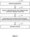
- FIG. 3 is a flow diagram illustrating an example technique for forming deposit 14 on surface 16 of substrate 12 that includes cold spraying first particles and second particles of a metal alloy.
- the technique of FIG. 3 will be described with concurrent reference to article 10 of FIG. 1A and system 30 of FIG. 2 .
- other systems may be used to perform the technique of FIG. 3
- the technique of FIG. 3 may be used to form other composite components, or both.
- the technique illustrated in FIG. 3 may optionally include preparing substrate 12 (50).
- Preparing substrate 12 may include any process or series of processes to prepare surface 16 of substrate 12 for deposition of deposit 14.
- preparing substrate 12 may include forming substrate 12.
- forming substrate 12 may include forging, casting, or performing other metallurgy techniques to define a shape of substrate 12.
- preparing substrate 12 may include surface preparation of surface 16, such as, for example, abrading surface 16 and/or coating surface 16 with a coating configured to improve bonding of deposit 14 or to improve mechanical properties or chemical properties of article 10, such as one or more thermal barrier coatings or environmental barrier coatings.
- preparing substrate 12 may include treatment of a crack, chip, discontinuity, or other damaged feature for repair by deposit 14.
- a crack may be smoothed, roughened, or otherwise treated to improve deposition or bonding of deposit 14 to the surface of the crack.
- the technique illustrated in FIG. 3 may optionally include selecting, by system 30, a composition of heat-treated particles and non-heat-treated particles (52).
- the composition of first particles and second particles in high velocity particle stream 48 may include a relative composition (e.g., a ratio) of the first and second particles.
- computing device 40 may hold constant the composition of the first particles and second particles throughout the cold spray deposition process, such as for a deposit having substantially homogenous properties, while in other examples, computing device 40 may vary the composition of the first particles and the second particles during the cold spray deposition process, such as for a deposit having a spatially varying composition.
- computing device 40 may receive, such as from a user input, a desired composition of deposit 14.
- the desired composition may represent a relative composition of first component 18, second component 20, and/or any other composition in resulting article 10.
- the technique illustrated in FIG. 3 includes cold spraying, by system 30, heat-treated particles and non-heat-treated particles on to at least a portion of surface 16 of substrate 12 (54).
- cold spraying involves using cold spray gun 32 and gas source 38 to accelerate first particles from first material source 34 and second particles from second material source 36 toward surface 16 of substrate 12 without melting the first and second particles.
- the first and second particles may contact surface 16 at velocities sufficient to cause plastic deformation of the particles and result in attachment or bonding of the particles to surface 16 and/or other attached particles defining build surface 46.
- cold spraying includes high pressure cold spraying.
- gas source 38 and material sources 34 and 36 may include pressurization systems to pressurize each of gases, first particles, and second particles.
- the technique illustrated in FIG. 3 may optionally include, after cold spraying the first and second particles to form first component 18 and second component 20, machining the deposited first component 18 and second component 20 to define deposit 14 (56).
- forming deposit 14 may include cold spraying excess first component 18 and second component 20 on to surface 16, then machining away the excess first component 18 and second component 20. Machining away the excess first component 18 and second component 20 may enable system 30 to form deposit 14 including more complex geometries, with increased precision (e.g., within predetermined tolerances), or both compared to a technique without machining.
- the subject-matter of the disclosure may also relate, among others, to the following aspects:
Landscapes
- Chemical & Material Sciences (AREA)
- Engineering & Computer Science (AREA)
- Materials Engineering (AREA)
- Mechanical Engineering (AREA)
- Chemical Kinetics & Catalysis (AREA)
- Metallurgy (AREA)
- Organic Chemistry (AREA)
- Physics & Mathematics (AREA)
- Thermal Sciences (AREA)
- Composite Materials (AREA)
- Manufacturing & Machinery (AREA)
- Other Surface Treatments For Metallic Materials (AREA)
Abstract
Description
- The disclosure relates to multi-component deposits and techniques for forming multi-component deposits.
- Heat treatment processes may be used to alter the physical properties of a component, such as a mechanical part, after the component has been formed. In a typical heat treatment process, a fabricated component may be heated to a predefined bulk temperature, such as a transformation temperature of the constituent material of the component, held at the temperature for a period of time to achieve a relatively uniform temperature throughout the component, and cooled at a predefined cooling rate to achieve a particular transformation of the constituent material of the component. As a result, the component may include a relatively uniform set of physical properties different from the initial set of physical properties of the component prior to heat treatment.
- The present disclosure provides a method and an article as set out in the appended claims.
- The disclosure describes example articles, and techniques and systems for forming the example articles, that include a deposit having a heat-treated component and either a non-heat-treated or a differently-heat-treated component.
- In some examples, the disclosure describes an example technique that includes cold spraying first particles and second particles of a metal alloy on at least a portion of a surface of a substrate to form a deposit on the surface of the substrate. The first and second particles have been subjected to different heat treatments prior to cold spraying. For example, the first particles may include particles that have undergone a heat treatment, while the second particles may include particles that have either undergone no heat treatment or undergone a different heat treatment than the first particles. Cold spraying involves accelerating the first particles and the second particles toward the surface of the substrate without melting or creating other thermally induced changes to a microstructure of the first and second particles. As a result, the first particles form a first, heat-treated component and the second particles form a second non-heat-treated or differently-heat-treated component, and the particles and substrate are not subject to a heat treatment during the cold spray process that may further modify their thermomechanical properties.
- In some examples, the disclosure describes an example article that includes a substrate defining a surface and a deposit on the surface of the substrate in which the deposit was formed using cold spraying. The deposit includes a first component and a second component. Cold spraying involves accelerating first particles and second particles of a metal alloy toward the surface of the substrate without creating thermally induced changes to a microstructure of the respective first and second particles. The first and second particles have been subjected to different heat treatments prior to cold spraying.
- The details of one or more examples are set forth in the accompanying drawings and the description below. Other features, objects, and advantages will be apparent from the description and drawings, and from the claims.
- The skilled person will appreciate that except where mutually exclusive, a feature or parameter described in relation to any one of the above aspects may be applied to any other aspect. Furthermore, except where mutually exclusive, any feature or parameter described herein may be applied to any aspect and/or combined with any other feature or parameter described herein.
- Embodiments will now be described by way of example only, with reference to the Figures, in which:
-
FIG. 1A is a conceptual cross-sectional view of an example article including a deposit that includes a first component and a second component. -
FIG. 1B is a conceptual cross-sectional view of an example article including a deposit that includes a first component and a second component. -
FIG. 2 is a conceptual and schematic block diagram of an example system for forming a deposit on a surface of a substrate by cold spraying first particles and second particles of a metal alloy on the surface of the substrate. -
FIG. 3 is a flow diagram illustrating an example technique for forming a deposit on a surface of a substrate by cold spraying first particles and second particles of a metal alloy on the surface of the substrate. - Aspects and embodiments of the present disclosure will now be discussed with reference to the accompanying figures. Further aspects and embodiments will be apparent to those skilled in the art.
- The disclosure generally describes example systems and techniques for depositing heat treated metal alloys and, optionally, non-heat-treated metal alloys onto a substrate without exposing the substrate to high temperatures. The example techniques involve cold spraying metal alloy particles onto a substrate to form a deposit. These cold sprayed metal alloy particles include a mix of particles having a metal alloy that has been heat treated ("heat-treated particles") and particles having the same metal alloy that either has not been heat treated ("non-heat-treated particles") or has been heat treated with a different heat-treatment ("differently-heat-treated particles"). Heat-treated particles may have properties, such as tensile strength and elongation, that are improved compared to non-heat-treated particles of the same composition. In cold spraying, the heat-treated particles, non-heat-treated particles, and/or differently-heat-treated particles are directed toward and impact the substrate while having temperatures that remain below a temperature at which the particles experience thermally induced property changes. The cold sprayed particles bond with previously deposited particles to form a two-component deposit that includes a heat-treated component and either a non-heat-treated component or a differently-heat-treated component.
- In some examples, the techniques discussed herein incorporate heat-treated materials into an article without exposing an underlying substrate of the article or materials in the deposit to temperature conditions experienced during heat treatment processes. For example, deposition of a heat-treated metal alloy layer may involve first depositing the metal alloy layer and subsequently exposing both the metal alloy layer and the substrate to heat treatment conditions, including high temperature conditions for extended periods of time and/or fast cooling conditions. These high temperature and/or fast cooling conditions may damage the substrate and/or produce undesired changes in properties of the substrate. Cold spray deposition of heat-treated particles may occur below the melting point or other transition temperature of the metal alloy and without bulk heating of the underlying substrate or deposited material, such that the underlying substrate or deposited material is exposed to lower temperatures than techniques that incorporate heat-treated materials onto a substrate without cold spraying. As such, properties of the heat-treated particles, non-heat-treated particles, and/or differently-heat-treated particles may be substantially unchanged after cold spraying.
- In some examples, the techniques discussed herein incorporate a blend of various heat-treated materials and non-heat-treated materials into an article. For example, heat treatment of a metal alloy layer may involve bulk heating the metal alloy layer to a substantially uniform temperature to produce a metal alloy layer with substantially homogeneous properties. Cold spray deposition of the heat-treated particles and differently-heat-treated or non-heat-treated particles may produce a deposit that includes properties, such as tensile strength and elongation, derived from the heat-treated material, and either and the non-heat-treated material or the differently-heat-treated material, such that deposits formed from a mix of heat-treated particles and differently-heat-treated or non-heat-treated particles may include a greater variety of properties than deposits formed from heat-treated or non-heat-treated materials alone.
-
FIG. 1A is a conceptual cross-sectional view of anexample article 10A that includes asubstrate 12 and adeposit 14. In some examples,article 10A may be a component of a gas turbine engine. For example,article 10A may be a component with a barrier coating, a repaired component, a multi-layer component, or the like. Due to high temperatures experienced in gas turbine engine, components of gas turbine engines may incorporate heat treated materials to relieve residual stresses and increase desired properties. In some examples,substrate 12 includes a bulk material, such as a forged metal, a cast metal, or a sheet metal, that may be substantially homogeneous (e.g., homogeneous or nearly homogeneous to the extent possible by common metallurgy techniques). Bulk materials that may be used forsubstrate 12 include, but are not limited to, Ni-based alloys, Co-based alloys, Ti-based alloys, or Fe-based alloys.Substrate 12 defines asurface 16.Surface 16 may have a variety of surface conditions including, but not limited to, an as-manufactured surface, a damaged surface, or the like. -
Deposit 14 is on at least a portion ofsurface 16 ofsubstrate 12. While shown inFIG. 1A as covering an entirety ofsurface 16, in some instances,deposit 14 may only cover a particular area, such as a portion ofarticle 10A that may experience abrasion, high temperatures, or other external phenomena that induce stresses and/or fractures.Deposit 14 may represent a one or more of a variety of functional deposits of the metal alloy onsubstrate 12 including, but not limited to: a structure functionally differentiated fromsubstrate 12, such as a flange or other structure extending from and/or complementary tosubstrate 12; a repair joint ofsubstrate 12, such as a filler; a coating onsubstrate 12, such as a barrier coating; a layer onsubstrate 12, such as a layer in a multi-layer part; or the like. - In some examples,
deposit 14 may be configured to improve properties ofsubstrate 12. For example,substrate 12 may be a damaged component having crackedsurface 16 that includes one or more cracks that extend intosubstrate 12. Rather than replacesubstrate 12 with a new part orrepair substrate 12 using high temperature techniques, such as welding or post-deposition heat treatment,deposit 14 may be formed within the one or more cracks to fill the cracks. As a result,substrate 12 may have improved properties, such as strength aerodynamic shape, or the like, compared tosubstrate 12 prior to receivingdeposit 14. In some examples,deposit 14 andsubstrate 12 include the same composition, such thatarticle 10A may have a substantially homogeneous composition after repair ofsubstrate 12. In some examples,deposit 14 andsubstrate 12 may include different compositions. For example, a particular composition ofdeposit 14 may be better suited (e.g., more easily bond withsubstrate 12 using cold spraying, etc.) as a filler for cracks than a composition ofsubstrate 12. - In some examples,
deposit 14 may be configured to protectsubstrate 12 from physical impact or chemical reactants. For example,substrate 12 may be a high temperature component, such that portions ofsubstrate 12 nearsurface 16 may face a high temperature environment with reducing agents, such as calcia-magnesia-alumina-sulfur (CMAS), that may damagesubstrate 12. To protectsubstrate 12 from these agents,deposit 14 may extend continuously acrosssurface 16 to provide a dense, high strength barrier forsubstrate 12. - In some examples,
deposit 14 may be configured to complementsubstrate 12 as a separate structure that provides additional functionality tosubstrate 12. For example,deposit 14 may include a mechanical component, such as a flange, that is mechanically coupled tosubstrate 12 and configured to perform a different function thansubstrate 12. -
Deposit 14 includes a metal alloy. Metal alloys may have constituent elements that, when subjected to various heat treatments, undergo phase transformations or migrate from solution to change a microstructure ofdeposit 14. The metal alloy ofdeposit 14 may include any metal alloy whose properties may change, such as through changes in microstructure or homogeneity of the metal alloy, in response to heat treatment processes. Metal alloys that may be used include, but are not limited to, Mg-based alloys, Ni-based alloys, Ti-based alloys, Fe-based alloys, Al-based alloys, Co-based alloys, Ta-based alloys, Nb-based alloys, Zn-based alloys, Cr-based alloys, and Cu-based alloys. -
Deposit 14 is deposited onsurface 16 using cold spraying techniques. As will be explained further inFIG. 2 below, cold spraying involves accelerating first particles (e.g., heat-treated particles) and second particles (e.g., differently-heat-treated or non-heat-treated particles) of the metal alloy constituting at least a portion ofdeposit 14 towardsurface 16 ofsubstrate 12. Upon impactingsurface 16 or a working surface ofdeposit 14, the first and second particles undergo deformation and bond tosubstrate 12 and/or previously deposited particles without melting. As a result of cold spray deposition of the first and second particles,deposit 14 may have a very dense microstructure and an interface withsubstrate 12 that is substantially free of voids, and may be characterized by grain boundaries and dislocation networks formed at interfaces of localized deposits corresponding to deposited first and second particles.Deposit 14 formed from the first and second particles may have the same or nearly the same microstructure as the first and second particles before spraying, i.e., there is no thermally induced microstructure change to the particles themselves. This may allow better control of the properties of the particles/domains/regions in the deposit compared to cases where melting occurs during spraying. -
Deposit 14 includes a first component 18 (e.g., a heat-treated component) and a second component 20 (e.g., a differently-heat-treated or non-heat-treated component). While shown as visually differentiated elements (e.g., interfaces between deposits) inFIG. 1A to emphasize a relationship offirst component 18 andsecond component 20 to first particles and second particles, respectively, it will be understood that deposits of heat-treated metal alloys corresponding tofirst component 18 and non-heat-treated or differently-heat-treated metal alloys corresponding tosecond component 20 may not be differentiated by clear physical boundaries due to bonding of the metal alloy deposits from the particles, and that portions ofdeposit 14 corresponding tofirst component 18 andsecond component 20 may be differentiated by any differences in properties derived from heat treatment processes of the metal alloy, as will be described further below. -
First component 18 may include any portion ofdeposit 14 that includes a metal alloy that has undergone heat treatment prior to deposition onsurface 16. Heat treatment may include any process that involves application of heat or cold to a bulk material to change properties of the bulk material.First component 18 may include a heat-treated metal alloy formed from a variety of heat treatments including, but not limited to, annealing, hardening (e.g., aging), surface hardening, and the like. Mechanical properties offirst component 18 may depend on a composition offirst component 18, a type of heat treatment previously applied tofirst component 18, and/or various parameters used to cold spray heat-treated particles of the metal alloy onsurface 16. -
Second component 20 may include any portion ofdeposit 14 that includes a metal alloy that has been subjected to a different heat treatment thanfirst component 18, such as no heat treatment or another heat treatment. Whilesecond component 20 may have a same composition (i.e., same chemistry) asfirst component 18,second component 20 may have properties that are different from, and may be complementary to,first component 18. In some examples,second component 20 includes a metal alloy that has not undergone or been subjected to heat treatment. For example,second component 20 may include a metal alloy that has not undergone an amount (e.g., high enough temperature, long enough period of time) of bulk heating or cooling sufficient to cause a change in microstructure or homogeneity of the metal alloy. In some examples,second component 20 includes a metal alloy that has undergone or been subjected to a different heat treatment thanfirst component 18. In some examples, the second component may include a heat-treated composition having a same chemistry and different heat treatment asfirst component 18. For example,second component 20 may include a metal alloy that has undergone a heat treatment that has caused different changes in microstructure or homogeneity of the metal alloy than the heat treatment offirst component 18. Certain heat treatments directed toward creating more homogeneous microstructures, such as annealing, may complement heat-treatments directed toward precipitating constituents, such as hardening, such thatdeposit 14 may have a blend of properties that result from more than one heat-treatment.First component 18 may include a heat-treated metal alloy formed from a variety of heat treatments including, but not limited to, annealing, hardening (e.g., aging), surface hardening, and the like. -
First component 18 and/orsecond component 20 may be selected for a variety of properties including, but not limited to, tensile strength, yield strength, hardness, toughness, percent elongation, percent reduction, Young's modulus, and the like. For example, the composition of the metal alloy offirst component 18 andsecond component 20 and/or the heat treatment process corresponding tofirst component 18 may be selected for any properties of either of the heat-treated metal alloy and/or the non-heat-treated metal alloy. As one example in which deposit 14 is a barrier coating,first component 18 may be selected for high hardness. As another example in which deposit 14 is a repair joint,first component 18 may be selected for high ductility/elongation, high toughness, and/or high tensile strength. Properties offirst component 18 andsecond component 20, such as tensile strength, elongation, and yield strength, may be measured using test methods such as, for example, ASTM E8 Standard Test Methods for Tension Testing of Metallic Materials, such as for samples that includefirst component 18 and/orsecond component 20, individually or as a blended cold-spray deposit. - In some examples,
first component 18 includes a hardened metal alloy formed from a hardening process. For example, hardening may increase tensile strength and ductility (i.e., elongation) of the metal alloy, such thatdeposit 14 that includesfirst component 18 may have a greater toughness than deposits that do not include a hardened component; reduce hardness of the metal alloy; create a more stable metal alloy that may age less in service; and/or modify surface properties of the first particles that formfirst component 18, which may change behaviors of the metal alloy within the bulk ofdeposit 14. In some examples,first component 18 includes at least one of a precipitation hardened metal alloy, a quenched hardened metal alloy, or a tempered metal alloy. In some examples, a tensile strength offirst component 18 is at least about twice as high as a tensile strength ofsecond component 20, such as at least about 5 times higher. For example, hardened aluminum may have a tensile strength of about 20,000 PSI or higher, while non-hardened aluminum may have a tensile strength of about 4000 PSI. In some examples, a percent elongation offirst component 18 is at least about 50% higher than a percent elongation ofsecond component 20. For example, hardened aluminum may have a percent elongation of about 4-8%, while a non-hardened aluminum may have a percent elongation of about 2-4%. - As a result of incorporation of both
first component 18 andsecond component 20,deposit 14 may have bulk properties derived fromfirst component 18 andsecond component 20 that are different from properties offirst component 18 orsecond component 20 individually. For example, whilefirst component 18 may have improved properties such as tensile strength and ductility as compared tosecond component 20,first component 18 may have increased brittleness, which may increase susceptibility to cracking. However,second component 20 may moderate these properties, such thatdeposit 14 may have values of bulk properties that are between the individual properties of eitherfirst component 18 orsecond component 20. A volume ratio offirst component 18 andsecond component 20 may be selected to achieve a particular set of properties derived from a relative volume offirst component 18 and a volume ofsecond component 20. In some examples, a volume percentage offirst component 18 indeposit 14 is between about 1% and about 99%, such as between about 10% and about 90%, or between about 30% and about 70%. -
First component 18 andsecond component 20 may be distributed throughoutdeposit 14 in various concentrations and distributions. For example, due to incremental deposition of first and second particles during cold spraying, distribution (e.g., parallel or normal to surface 16 of substrate 12) offirst component 18 andsecond component 20 may be adjusted temporally and/or spatially. In some examples,first component 18 andsecond component 20 may be distributed substantially homogenously throughoutdeposit 14, such thatdeposit 14 may have relatively uniform bulk properties. In some examples,first component 18 andsecond component 20 may be non-homogeneously distributed throughoutdeposit 14, such thatdeposit 14 may have non-uniform bulk properties. For example, a concentration offirst component 18 may be higher in a first portion ofdeposit 14, such asnear surface 16, than a second portion ofdeposit 14 to provide properties that may be more suitable for the corresponding portion. - In some examples, in addition to incorporating the metal alloy of
first component 18 andsecond component 20,deposit 14 may include other components that provide alternative or additional functionality to deposit 14. For example,deposit 14 may include the metal alloy as a first composition and may include another composition, such as another metal, metal alloy, or ceramic, as a third component. For example, the second composition may include various properties that complementfirst component 18 and/orsecond component 20. - In the example of
FIG. 1A , regions ofdeposit 14 corresponding tofirst component 18 andsecond component 20 are illustrated as having a similar size. For example, a substantially uniform size may correspond to more uniform grain boundaries. However, in some examples, regions ofdeposit 14 corresponding tofirst component 18 andsecond component 20 may have different sizes.FIG. 1B is a conceptual cross-sectional view of anexample article 10B including a deposit that includes a first component and a second component. As illustrated inFIG. 1B , deposits corresponding tofirst component 18 andsecond component 20 may have different sizes. Such different sized deposits offirst component 18 andsecond component 20 may result from different sized first and second particles. In some instances, different size particles may change a behavior ofdeposit 14 under load. For example, without being limited to any particular theory,second component 20 may have smaller deposits offirst component 18 at an interface of deposits ofsecond component 20 andfirst component 18 boundary. These different sizes of the deposits may impact deformation at the boundaries when under load, such that the smaller deposits may lock the boundary and reduce deformation at the boundary. - Articles described herein may be produced using cold spray deposition systems.
FIG. 2 is a conceptual and schematic block diagram of anexample system 30 for formingdeposit 14 using cold spraying.System 30 is configured to formdeposit 14 onsubstrate 12 by cold spraying first particles and second particles of a metal alloy on at least a portion ofsurface 16 ofsubstrate 12.System 30 may include anenclosure 42, which encloses astage 44, acold spray gun 32, afirst material source 34, asecond material source 36, and agas source 38.System 30 may further include acomputing device 40, which is communicatively connected to stage 44,cold spray gun 32,first material source 34,second material source 36, andgas source 38. -
Article 10 is positioned withinenclosure 42.Enclosure 42 may substantially enclose (e.g., enclose or nearly enclose)stage 44,cold spray gun 32,first material feed 34,second material feed 36,gas source 38, andarticle 10.Enclosure 42 may maintain a desired atmosphere (e.g., an atmosphere that is substantially inert to the materials from which deposit 14 is formed) aroundsubstrate 12 anddeposit 14 during the cold spray technique. In some examples,stage 44 may be configured to selectively position and restrainarticle 10 in place relative to stage 44 during formation ofdeposit 14. In some examples,stage 44 is movable relative tocold spray gun 32. For example,stage 44 may be translatable and/or rotatable along at least one axis to positionarticle 10 relative tocold spray gun 32. Similarly, in some examples,cold spray gun 32 may be movable relative to stage 44 to positioncold spray gun 32 relative toarticle 10. In some examples,system 30 may not includeenclosure 42 andstage 44. For example,system 30 may include a portable device configured to cold spray the heat-treated and non-heat-treated metal alloy particles in situ, such as during a repair. In such examples,system 30 may include temporary containment asenclosure 42. -
First material source 34 andsecond material source 36 may each be configured to supply first particles and second particles, respectively, tocold spray gun 32. Eachmaterial source material sources gas source 38, such thatgas source 38 enablesmaterial sources cold spray gun 32.Computing device 40 may be communicatively coupled tofirst material source 34 andsecond material source 36 to control a rate of flow of first particles and second particles, respectively, frommaterial sources cold spray gun 32 via a material feed. For example,computing device 40 may control a valve or a feeder system of the material feed. In addition tofirst material source 34 andsecond material source 36,system 30 may include other material sources, such as for a second composition. While shown as separate equipment, in some examples,first material source 34 andsecond material source 36 may be the same equipment. For example, first particles and second particles may be pre-mixed prior to being fed intocold spray gun 32. - The first particles and second particles may have properties corresponding to localized properties of
first component 18 andsecond component 20, respectively, ofdeposit 14, as described inFIG. 1A above. For example, the first particles may be selected to providedeposit 14 with particular properties resulting from a particular heat treatment including, but not limited to, tensile strength, yield strength, hardness, toughness, percent elongation, percent reduction, Young's modulus, and the like. In some examples, the first particles include at least one of a precipitation hardened metal alloy, a quenched hardened metal alloy, or a tempered metal alloy. In some examples, a tensile strength of the first particles is at least about 10% greater than a tensile strength of the second particles. In some examples, a percent elongation of the first particles is at least about 10% greater than a percent elongation of the second particles. - The first particles and second particles may include any suitable particle size. For example, the size range of the first and second particles may be between about 1 micrometer (µm) and about 50 µm, such as between about 5 µm and about 20 µm. The size range of the first and second particles may be selected to achieve a selected impact velocity, e.g., a velocity of the particles when impacting
surface 16. In some examples, an average size of the first particles and the second particles may be different. -
Gas source 38 may be configured to accelerate the first and second particles fromfirst material source 34 andsecond material source 36, respectively.Gas source 38 may include, for example, a source of helium, nitrogen, argon, or other substantially inert gas, which may function as carrier of the particles.Gas source 38 may be fluidically coupled to a gas feed, which may control a flow rate and/or pressure of gas delivered tocold spray gun 32. In some examples, the gas feed may include a heater to heat the gas. The pressure of the gas ingas source 38 may be sufficient to achieve supersonic velocities of the gas and/or particles at the outlet of a nozzle. In some examples, the pressure of the gas may be between about 0.1 megapascals (MPa) and about 2 MPa, such as between about 0.5 MPa and about 1.5 MPa. In some examples, the supersonic velocities may be between about 500 meters per second (m/s) to about 1000 m/s. -
Cold spray gun 32 may be configured to entrain the first particles fromfirst material source 34 and the second particles fromsecond material source 36 in the flow of gas fromgas source 38 through a nozzle. The nozzle may accelerate the gas and plurality of particles to high velocities. The resultant highvelocity particle stream 48 may be directed towardsurface 16 ofsubstrate 12. Without limiting the description to a specific theory, the high velocity of the plurality of particles may be sufficient to cause plastic deformation of the particles upon impact withsurface 16 ofsubstrate 12. This process may be repeated as particles attach to surface 16 and/or other attached particles defining abuild surface 46 ofdeposit 14. -
System 30 may be configured to control relative movement of highvelocity particle stream 48 with respect to surface 16 ofsubstrate 12 and/or buildsurface 46. For example, directing highvelocity particle stream 48 towardsubstrate 12 may result in deposition of the plurality of particles onsurface 16 ofsubstrate 12 and/or buildsurface 46. As illustrated inFIG. 2 , the first particles and the second particles may accumulate to formdeposit 14. For example, highvelocity particle stream 48 may be moved oversurface 16 and/or buildsurface 46 until a sufficient amount of the heat-treated metal alloy and the non-heat-treated metal alloy has accumulated to define, at least roughly,deposit 14. For example, excess metal alloy may be deposited to form a structure with larger dimensions than a final structure ofdeposit 14, then excess metal alloy may be machined away to definedeposit 14. Although not illustrated inFIG. 2 ,system 30 may also include a milling device or machining device configured to remove deposited metal alloy to define a final shape ofdeposit 14. -
Computing device 40 may include, for example, a desktop computer, a laptop computer, a tablet, a workstation, a server, a mainframe, a cloud computing system, or the like.Computing device 40 may include or may be one or more processors or processing circuitry, such as one or more digital signal processors (DSPs), general purpose microprocessors, application specific integrated circuits (ASICs), field programmable logic arrays (FPGAs), or other equivalent integrated or discrete logic circuitry. Accordingly, the term "processor," as used herein may refer to any of the foregoing structure or any other structure suitable for implementation of the techniques described herein. In addition, in some examples, the functionality ofcomputing device 40 may be provided within dedicated hardware and/or software modules. -
Computing device 40 is configured to control operation ofsystem 30, including, for example,stage 44,cold spray gun 32,material sources gas source 38.Computing device 40 may be configured to control operation ofstage 44 and/orcold spray gun 32 to positionarticle 10 relative tocold spray gun 32. For example, as described above,computing device 40 may controlstage 44 and/orcold spray gun 32 to translate and/or rotate along at least one axis to positionarticle 10 relative tocold spray gun 32. -
Computing device 40 may control at least one of the feed rate of the first particles fromfirst material source 34, second particles fromsecond material source 36, pressure fromgas source 38, flow rate of the gas fromgas source 38, the movement of highvelocity particle stream 48 relative toarticle 10, a distance betweencold spray gun 32 and buildsurface 46, the angle of the high velocity particle stream relative to buildsurface 46, and a width of overlap between adjacent passes of the high velocity particle stream and the velocity ofcold spray gun 32 relative to buildsurface 46.Computing device 40 may control at least one of these parameters to control an amount of material, such as heat-treated metal alloy and non-heat-treated metal alloy, added toarticle 10 at a given time and location and/or to control metallurgical properties of the added material. In some examples,cold spray gun 32 may be scanned (e.g., translated) relative to deposit 14, anddeposit 14 will include a general shape corresponding to the scanned path. - The articles described herein may be formed using any suitable technique.
FIG. 3 is a flow diagram illustrating an example technique for formingdeposit 14 onsurface 16 ofsubstrate 12 that includes cold spraying first particles and second particles of a metal alloy. The technique ofFIG. 3 will be described with concurrent reference toarticle 10 ofFIG. 1A andsystem 30 ofFIG. 2 . In other examples, other systems may be used to perform the technique ofFIG. 3 , the technique ofFIG. 3 may be used to form other composite components, or both. - In some examples, the technique illustrated in
FIG. 3 may optionally include preparing substrate 12 (50). Preparingsubstrate 12 may include any process or series of processes to preparesurface 16 ofsubstrate 12 for deposition ofdeposit 14. In some examples, preparingsubstrate 12 may include formingsubstrate 12. For example, formingsubstrate 12 may include forging, casting, or performing other metallurgy techniques to define a shape ofsubstrate 12. In some examples, preparingsubstrate 12 may include surface preparation ofsurface 16, such as, for example, abradingsurface 16 and/orcoating surface 16 with a coating configured to improve bonding ofdeposit 14 or to improve mechanical properties or chemical properties ofarticle 10, such as one or more thermal barrier coatings or environmental barrier coatings. In some examples, preparingsubstrate 12 may include treatment of a crack, chip, discontinuity, or other damaged feature for repair bydeposit 14. For example, one or more surfaces of a crack may be smoothed, roughened, or otherwise treated to improve deposition or bonding ofdeposit 14 to the surface of the crack. - In some examples, the technique illustrated in
FIG. 3 may optionally include selecting, bysystem 30, a composition of heat-treated particles and non-heat-treated particles (52). The composition of first particles and second particles in highvelocity particle stream 48 may include a relative composition (e.g., a ratio) of the first and second particles. In some examples,computing device 40 may hold constant the composition of the first particles and second particles throughout the cold spray deposition process, such as for a deposit having substantially homogenous properties, while in other examples,computing device 40 may vary the composition of the first particles and the second particles during the cold spray deposition process, such as for a deposit having a spatially varying composition. For example,computing device 40 may receive, such as from a user input, a desired composition ofdeposit 14. The desired composition may represent a relative composition offirst component 18,second component 20, and/or any other composition in resultingarticle 10. - The technique illustrated in
FIG. 3 includes cold spraying, bysystem 30, heat-treated particles and non-heat-treated particles on to at least a portion ofsurface 16 of substrate 12 (54). As discussed above in reference toFIG. 1A , cold spraying involves usingcold spray gun 32 andgas source 38 to accelerate first particles fromfirst material source 34 and second particles fromsecond material source 36 towardsurface 16 ofsubstrate 12 without melting the first and second particles. The first and second particles may contactsurface 16 at velocities sufficient to cause plastic deformation of the particles and result in attachment or bonding of the particles to surface 16 and/or other attached particles definingbuild surface 46. In some examples, cold spraying includes high pressure cold spraying. For example,gas source 38 andmaterial sources - In some examples, the technique illustrated in
FIG. 3 may optionally include, after cold spraying the first and second particles to formfirst component 18 andsecond component 20, machining the depositedfirst component 18 andsecond component 20 to define deposit 14 (56). For example, formingdeposit 14 may include cold spraying excessfirst component 18 andsecond component 20 on tosurface 16, then machining away the excessfirst component 18 andsecond component 20. Machining away the excessfirst component 18 andsecond component 20 may enablesystem 30 to formdeposit 14 including more complex geometries, with increased precision (e.g., within predetermined tolerances), or both compared to a technique without machining. - The subject-matter of the disclosure may also relate, among others, to the following aspects:
- Aspect 1. A method comprising: cold spraying first particles and second particles of a metal alloy on at least a portion of a surface of a substrate to form a deposit on the surface of the substrate, wherein the first particles form a first component of the deposit and the second particles form a second component of the deposit, wherein cold spraying comprises accelerating the first particles and the second particles toward the surface of the substrate without creating thermally induced changes to a microstructure of the respective first and second particles, and wherein the first and second particles have been subjected to different heat treatments prior to cold spraying.
- Aspect 2. The method of Aspect 1, wherein the first particles comprise at least one of precipitation hardened particles, quenched hardened particles, or tempered particles.
- Aspect 3. The method of Aspect 1, wherein a volume percentage of the first component in the deposit is between about 1% and about 99%.
- Aspect 4. The method of Aspect 1, wherein the metal alloy comprises at least one of a Mg-based alloy, a Ni-based alloy, a Ti-based alloy, a Fe-based alloy, an Al-based alloy, a Co-based alloy, a Ta-based alloy, a Nb-based alloy, a Zn-based alloy, a Cr-based alloy, or a Cu-based alloy.
- Aspect 5. The method of Aspect 1, wherein the surface comprises a cracked surface, and wherein forming the deposit further comprises filling the cracked surface with the deposit.
- Aspect 6. The method of Aspect 1, wherein a tensile strength of the first particles is at least about twice as high as a tensile strength of the second particles.
- Aspect 7. The method of Aspect 1, wherein an elongation of the first particles is at least about 50% greater than an elongation of the second particles.
- Aspect 8. The method of Aspect 1, wherein the metal alloy comprises a first composition, and wherein the method further comprises forming the substrate from a second composition, different from the first composition.
- Aspect 9. The method of Aspect 1, wherein the first and second particles and the substrate are not subject to a heat treatment during the cold spraying that would further modify thermomechanical properties of the first and second particles and the substrate.
-
Aspect 10. The method of Aspect 1, wherein the second composition comprises the metal alloy that has not been subjected to a heat treatment prior to cold spraying. - Aspect 11. An article comprising: a substrate defining a surface; and a deposit on the surface of the substrate, wherein the deposit was formed using cold spraying, wherein the deposit comprises a first component and a second component, wherein cold spraying comprises accelerating first particles and second particles of a metal alloy toward the surface of the substrate without creating thermally induced changes to a microstructure of the respective first and second particles, and wherein the first and second particles have been subjected to different heat treatments prior to cold spraying.
-
Aspect 12. The article of Aspect 11, wherein the first particles comprise at least one of precipitation hardened particles, quenched hardened particles, or tempered particles. - Aspect 13. The article of Aspect 11, wherein a volume percentage of the first component in the deposit is between about 1% and about 99%.
-
Aspect 14. The article of Aspect 11, wherein the metal alloy comprises at least one of Mg-based alloys, Ni-based alloys, Ti-based alloys, Fe-based alloys, Al-based alloys, Co-based alloys, Ta-based alloys, Nb-based alloys, Zn-based alloys, Cr-based alloys, and Cu-based alloys. - Aspect 15. The article of Aspect 11, wherein the surface comprises a cracked surface, and wherein the deposit fills at least a portion of the cracked surface.
-
Aspect 16. The article of Aspect 11, wherein a tensile strength of the first particles is at least about twice as high as a tensile strength of the second particles. - Aspect 17. The article of Aspect 11, wherein an elongation of the first particles is at least about 50% greater than an elongation of the second particles.
-
Aspect 18. The article of Aspect 11, wherein the metal alloy comprises a first composition, and wherein the substrate comprises a second composition, different from the first composition. - Aspect 19. The article of Aspect 11, wherein the first and second particles and the substrate are not subject to a heat treatment during the cold spraying that would further modify thermomechanical properties of the first and second particles and the substrate.
-
Aspect 20. The article of Aspect 11, wherein the second particles comprise the metal alloy that has not been subjected to a heat treatment prior to cold spraying. - Various examples have been described. These and other examples are within the scope of the following claims.
Claims (15)
- A method comprising:cold spraying first particles and second particles of a metal alloy on at least a portion of a surface (16) of a substrate (12) to form a deposit (14) on the surface of the substrate,wherein the first particles form a first component (18) of the deposit and the second particles form a second component (20) of the deposit,wherein cold spraying comprises accelerating the first particles and the second particles toward the surface (16) of the substrate (12) without creating thermally induced changes to a microstructure of the respective first and second particles, andwherein the first and second particles have been subjected to different heat treatments prior to cold spraying.
- The method of claim 1, wherein the first particles comprise at least one of precipitation hardened particles, quenched hardened particles, or tempered particles.
- The method of claim 1 or 2, wherein a volume percentage of the first component (18) in the deposit(14) is between 1% and 99%.
- The method of any preceding claim, wherein the metal alloy comprises at least one of a Mg-based alloy, a Ni-based alloy, a Ti-based alloy, a Fe-based alloy, an Al-based alloy, a Co-based alloy, a Ta-based alloy, a Nb-based alloy, a Zn-based alloy, a Cr-based alloy, or a Cu-based alloy.
- The method of any preceding claim, wherein the surface (16) comprises a cracked surface, and wherein forming the deposit (14) further comprises filling the cracked surface with the deposit.
- The method of claim 1, wherein a tensile strength of the first particles is at least about twice as high as a tensile strength of the second particles.
- The method of any preceding claim, wherein an elongation of the first particles is at least about 50% greater than an elongation of the second particles.
- The method of any preceding claim, wherein the metal alloy comprises a first composition, and wherein the method further comprises forming the substrate (12) from a second composition, different from the first composition.
- The method of any preceding claim, wherein the first and second particles and the substrate (12) are not subject to a heat treatment during the cold spraying that would further modify thermomechanical properties of the first and second particles and the substrate.
- The method of claim 8, wherein the second composition comprises the metal alloy that has not been subjected to a heat treatment prior to cold spraying.
- An article (1OA, 10B) comprising:a substrate (12) defining a surface (16); anda deposit (14) on the surface of the substrate, wherein the deposit was formed using cold spraying,wherein the deposit comprises a first component (18) and a second component (20),wherein cold spraying comprises accelerating first particles and second particles of a metal alloy toward the surface of the substrate (12) without creating thermally induced changes to a microstructure of the respective first and second particles, andwherein the first and second particles have been subjected to different heat treatments prior to cold spraying.
- The article of claim 11, wherein:the first particles comprise at least one of precipitation hardened particles, quenched hardened particles, or tempered particles;a volume percentage of the first component in the deposit is between 1% and 99%; and /orthe metal alloy comprises at least one of Mg-based alloys, Ni-based alloys, Ti-based alloys, Fe-based alloys, Al-based alloys, Co-based alloys, Ta-based alloys, Nb-based alloys, Zn-based alloys, Cr-based alloys, and Cu-based alloys.
- The article of claim 11 or 12, wherein:the surface comprises a cracked surface, wherein the deposit fills at least a portion of the cracked surface;a tensile strength of the first particles is at least about twice as high as a tensile strength of the second particles;an elongation of the first particles is at least about 50% greater than an elongation of the second particles; and/orthe metal alloy comprises a first composition, wherein the substrate comprises a second composition, different from the first composition.
- The article of any one of claims 11 to 13, wherein the first and second particles and the substrate are not subject to a heat treatment during the cold spraying that would further modify thermomechanical properties of the first and second particles and the substrate.
- The article of any one of claims 11 to 14, wherein the second particles comprise the metal alloy that has not been subjected to a heat treatment prior to cold spraying.
Applications Claiming Priority (1)
| Application Number | Priority Date | Filing Date | Title |
|---|---|---|---|
| US16/657,854 US20210115566A1 (en) | 2019-10-18 | 2019-10-18 | Multi-component deposits |
Publications (2)
| Publication Number | Publication Date |
|---|---|
| EP3808873A1 true EP3808873A1 (en) | 2021-04-21 |
| EP3808873B1 EP3808873B1 (en) | 2022-01-19 |
Family
ID=72561617
Family Applications (1)
| Application Number | Title | Priority Date | Filing Date |
|---|---|---|---|
| EP20196840.1A Active EP3808873B1 (en) | 2019-10-18 | 2020-09-18 | Multi-component deposits |
Country Status (3)
| Country | Link |
|---|---|
| US (2) | US20210115566A1 (en) |
| EP (1) | EP3808873B1 (en) |
| SG (1) | SG10202009705SA (en) |
Families Citing this family (2)
| Publication number | Priority date | Publication date | Assignee | Title |
|---|---|---|---|---|
| US20210115566A1 (en) | 2019-10-18 | 2021-04-22 | Rolls-Royce Corporation | Multi-component deposits |
| WO2022251910A1 (en) * | 2021-05-31 | 2022-12-08 | Composite Technology R & D Pty Limited | Additively manufactured metal casings |
Citations (4)
| Publication number | Priority date | Publication date | Assignee | Title |
|---|---|---|---|---|
| EP2604723A1 (en) * | 2011-12-16 | 2013-06-19 | General Electric Company | Cold spray of nickel-base alloys |
| WO2017220996A1 (en) * | 2016-06-20 | 2017-12-28 | The Welding Institute | Method of coating or repairing substrates |
| US20190009300A1 (en) * | 2017-07-06 | 2019-01-10 | General Electric Company | Method for repairing turbine component by application of thick cold spray coating |
| WO2019016779A1 (en) * | 2017-07-21 | 2019-01-24 | National Research Council Of Canada | Method for preparing powders for a cold spray process, and powders therefor |
Family Cites Families (19)
| Publication number | Priority date | Publication date | Assignee | Title |
|---|---|---|---|---|
| US3410732A (en) | 1965-04-30 | 1968-11-12 | Du Pont | Cobalt-base alloys |
| US6250362B1 (en) * | 1998-03-02 | 2001-06-26 | Alcoa Inc. | Method and apparatus for producing a porous metal via spray casting |
| EP1221125A4 (en) | 1999-09-16 | 2009-04-29 | Solidica Inc | CONSOLIDATION OF OBJECT BY DEPOSITION OF SEQUENTIAL MATERIAL |
| JP2006348349A (en) * | 2005-06-16 | 2006-12-28 | Katsuyoshi Kondo | Magnesium alloy powder raw material, high yield strength magnesium alloy, method for producing magnesium alloy powder raw material, and method for producing high yield strength magnesium alloy |
| US7618500B2 (en) | 2005-11-14 | 2009-11-17 | Lawrence Livermore National Security, Llc | Corrosion resistant amorphous metals and methods of forming corrosion resistant amorphous metals |
| CA2692959A1 (en) * | 2007-07-18 | 2009-01-22 | Alcan Technology & Management Ag | Duplex-aluminium material based on aluminium with a first phase and a second phase and method for producing the duplex-aluminium material |
| WO2009053156A2 (en) | 2007-10-26 | 2009-04-30 | H.C. Starck Gmbh | Metal powder mixture and the use thereof |
| JP5605901B2 (en) | 2010-09-30 | 2014-10-15 | 国立大学法人東北大学 | Method for repairing metal material by cold spray method, method for producing powder material for cold spray, and cold spray film |
| US20170226614A1 (en) * | 2016-02-05 | 2017-08-10 | The Board Of Trustees Of The University Of Illinois | Self-organized metal alloys for wear applications |
| JP6802079B2 (en) * | 2017-02-03 | 2020-12-16 | 日産自動車株式会社 | Manufacturing method of laminated members |
| JP6854140B2 (en) * | 2017-02-03 | 2021-04-07 | 日産自動車株式会社 | Laminated body, sliding member, and method of manufacturing the laminated body |
| US11179776B2 (en) * | 2017-06-28 | 2021-11-23 | Rolls-Royce Corporation | Joining metal or alloy components using electric current |
| DE102017222182A1 (en) * | 2017-12-07 | 2019-06-13 | Helmholtz-Zentrum Geesthacht Zentrum für Material- und Küstenforschung GmbH | A method of depositing a titanium aluminide alloy, titanium aluminide alloy and substrate comprising a titanium aluminide alloy |
| US11167864B2 (en) * | 2018-04-27 | 2021-11-09 | The Boeing Company | Applying cold spray erosion protection to an airfoil |
| CN112739851B (en) * | 2018-09-18 | 2023-04-07 | 日产自动车株式会社 | Film forming method |
| US11623387B2 (en) * | 2018-11-09 | 2023-04-11 | Effusiontech Ip Pty. Ltd. | Method of spray forming an object |
| CN113631756B (en) * | 2019-03-29 | 2023-03-14 | 日产自动车株式会社 | Film forming method |
| US11104998B2 (en) * | 2019-07-20 | 2021-08-31 | General Electric Company | Cold spray repair of engine components |
| US20210115566A1 (en) | 2019-10-18 | 2021-04-22 | Rolls-Royce Corporation | Multi-component deposits |
-
2019
- 2019-10-18 US US16/657,854 patent/US20210115566A1/en not_active Abandoned
-
2020
- 2020-09-18 EP EP20196840.1A patent/EP3808873B1/en active Active
- 2020-09-30 SG SG10202009705SA patent/SG10202009705SA/en unknown
-
2022
- 2022-04-04 US US17/657,884 patent/US12378677B2/en active Active
Patent Citations (4)
| Publication number | Priority date | Publication date | Assignee | Title |
|---|---|---|---|---|
| EP2604723A1 (en) * | 2011-12-16 | 2013-06-19 | General Electric Company | Cold spray of nickel-base alloys |
| WO2017220996A1 (en) * | 2016-06-20 | 2017-12-28 | The Welding Institute | Method of coating or repairing substrates |
| US20190009300A1 (en) * | 2017-07-06 | 2019-01-10 | General Electric Company | Method for repairing turbine component by application of thick cold spray coating |
| WO2019016779A1 (en) * | 2017-07-21 | 2019-01-24 | National Research Council Of Canada | Method for preparing powders for a cold spray process, and powders therefor |
Non-Patent Citations (1)
| Title |
|---|
| SABARD ALEXANDRE ET AL: "Inter-particle bonding in cold spray deposition of a gas-atomised and a solution heat-treated Al 6061 powder", JOURNAL OF MATERIAL SCIENCE, KLUWER ACADEMIC PUBLISHERS, DORDRECHT, vol. 54, no. 18, 12 June 2019 (2019-06-12), pages 12061 - 12078, XP037083300, ISSN: 0022-2461, [retrieved on 20190612], DOI: 10.1007/S10853-019-03736-W * |
Also Published As
| Publication number | Publication date |
|---|---|
| SG10202009705SA (en) | 2021-05-28 |
| US20220228267A1 (en) | 2022-07-21 |
| EP3808873B1 (en) | 2022-01-19 |
| US20210115566A1 (en) | 2021-04-22 |
| US12378677B2 (en) | 2025-08-05 |
Similar Documents
| Publication | Publication Date | Title |
|---|---|---|
| EP2011964B1 (en) | Method of Repairing a Turbine Component | |
| EP1674595B1 (en) | Structural repair using cold sprayed aluminum material | |
| Seraj et al. | The effect of traverse speed on deposition efficiency of cold sprayed Stellite 21 | |
| Bhowmik et al. | On the heat-treatment induced evolution of residual stress and remarkable enhancement of adhesion strength of cold sprayed Ti–6Al–4V coatings | |
| US12378677B2 (en) | Multi-component deposits | |
| EP2604723B1 (en) | Cold spray of nickel-base alloys | |
| Simpson et al. | Considerations for application of additive manufacturing to nuclear reactor core components | |
| US10315218B2 (en) | Method for repairing turbine component by application of thick cold spray coating | |
| US20060166020A1 (en) | High strength amorphous and microcrystaline structures and coatings | |
| Jasthi et al. | Microstructure and mechanical properties of cold spray additive manufactured Cu-Cr-Nb and Fe-Ni-Cr alloys | |
| EP2895634B1 (en) | A method for manufacturing a wear resistant component | |
| US20060134321A1 (en) | Blade platform restoration using cold spray | |
| Luo et al. | Improving the adhesion of cold sprayed Al deposits through in-situ micro-forging | |
| WO2017220996A1 (en) | Method of coating or repairing substrates | |
| Shim et al. | Bending strength of tool steel preheated to various temperatures and layered by direct energy deposition | |
| Majumdar et al. | 3-D printing by laser-assisted direct energy deposition (LDED): the present status | |
| EP1877598B1 (en) | Magnesium repair and build up | |
| CN114032537A (en) | Method for enhancing bonding strength of cold spraying coating and base material | |
| eun Jeong et al. | Effect of P21 buffer layer on interfacial bonding characteristics of high‑carbon tool steel hardfaced through directed energy deposition | |
| Sudigdo et al. | Cold spray of Ni-based superalloys: a review on processing and residual stress | |
| Lang et al. | IN718 cold gas repair spray of large cavities—microstructure and residual stresses | |
| RU2619419C2 (en) | Application method of titanium aluminide and product with titanium aluminide surface | |
| Hall et al. | Validation of a systematic approach to modeling spray quenching of aluminum alloy extrusions, composites, and continuous castings | |
| Story | Processing-microstructure-property relations in high pressure cold spray deposition of AA2024 and AA7075 | |
| Karthikeyan | Cold Spray Process |
Legal Events
| Date | Code | Title | Description |
|---|---|---|---|
| PUAI | Public reference made under article 153(3) epc to a published international application that has entered the european phase |
Free format text: ORIGINAL CODE: 0009012 |
|
| STAA | Information on the status of an ep patent application or granted ep patent |
Free format text: STATUS: THE APPLICATION HAS BEEN PUBLISHED |
|
| AK | Designated contracting states |
Kind code of ref document: A1 Designated state(s): AL AT BE BG CH CY CZ DE DK EE ES FI FR GB GR HR HU IE IS IT LI LT LU LV MC MK MT NL NO PL PT RO RS SE SI SK SM TR |
|
| AX | Request for extension of the european patent |
Extension state: BA ME |
|
| STAA | Information on the status of an ep patent application or granted ep patent |
Free format text: STATUS: REQUEST FOR EXAMINATION WAS MADE |
|
| GRAP | Despatch of communication of intention to grant a patent |
Free format text: ORIGINAL CODE: EPIDOSNIGR1 |
|
| STAA | Information on the status of an ep patent application or granted ep patent |
Free format text: STATUS: GRANT OF PATENT IS INTENDED |
|
| 17P | Request for examination filed |
Effective date: 20210923 |
|
| RBV | Designated contracting states (corrected) |
Designated state(s): AL AT BE BG CH CY CZ DE DK EE ES FI FR GB GR HR HU IE IS IT LI LT LU LV MC MK MT NL NO PL PT RO RS SE SI SK SM TR |
|
| RIC1 | Information provided on ipc code assigned before grant |
Ipc: C23C 24/04 20060101AFI20211013BHEP |
|
| INTG | Intention to grant announced |
Effective date: 20211027 |
|
| GRAS | Grant fee paid |
Free format text: ORIGINAL CODE: EPIDOSNIGR3 |
|
| GRAA | (expected) grant |
Free format text: ORIGINAL CODE: 0009210 |
|
| STAA | Information on the status of an ep patent application or granted ep patent |
Free format text: STATUS: THE PATENT HAS BEEN GRANTED |
|
| AK | Designated contracting states |
Kind code of ref document: B1 Designated state(s): AL AT BE BG CH CY CZ DE DK EE ES FI FR GB GR HR HU IE IS IT LI LT LU LV MC MK MT NL NO PL PT RO RS SE SI SK SM TR |
|
| REG | Reference to a national code |
Ref country code: GB Ref legal event code: FG4D |
|
| REG | Reference to a national code |
Ref country code: CH Ref legal event code: EP |
|
| REG | Reference to a national code |
Ref country code: DE Ref legal event code: R096 Ref document number: 602020001674 Country of ref document: DE |
|
| REG | Reference to a national code |
Ref country code: AT Ref legal event code: REF Ref document number: 1463843 Country of ref document: AT Kind code of ref document: T Effective date: 20220215 |
|
| REG | Reference to a national code |
Ref country code: IE Ref legal event code: FG4D |
|
| REG | Reference to a national code |
Ref country code: LT Ref legal event code: MG9D |
|
| REG | Reference to a national code |
Ref country code: NL Ref legal event code: MP Effective date: 20220119 |
|
| REG | Reference to a national code |
Ref country code: AT Ref legal event code: MK05 Ref document number: 1463843 Country of ref document: AT Kind code of ref document: T Effective date: 20220119 |
|
| PG25 | Lapsed in a contracting state [announced via postgrant information from national office to epo] |
Ref country code: NL Free format text: LAPSE BECAUSE OF FAILURE TO SUBMIT A TRANSLATION OF THE DESCRIPTION OR TO PAY THE FEE WITHIN THE PRESCRIBED TIME-LIMIT Effective date: 20220119 |
|
| PG25 | Lapsed in a contracting state [announced via postgrant information from national office to epo] |
Ref country code: SE Free format text: LAPSE BECAUSE OF FAILURE TO SUBMIT A TRANSLATION OF THE DESCRIPTION OR TO PAY THE FEE WITHIN THE PRESCRIBED TIME-LIMIT Effective date: 20220119 Ref country code: RS Free format text: LAPSE BECAUSE OF FAILURE TO SUBMIT A TRANSLATION OF THE DESCRIPTION OR TO PAY THE FEE WITHIN THE PRESCRIBED TIME-LIMIT Effective date: 20220119 Ref country code: PT Free format text: LAPSE BECAUSE OF FAILURE TO SUBMIT A TRANSLATION OF THE DESCRIPTION OR TO PAY THE FEE WITHIN THE PRESCRIBED TIME-LIMIT Effective date: 20220519 Ref country code: NO Free format text: LAPSE BECAUSE OF FAILURE TO SUBMIT A TRANSLATION OF THE DESCRIPTION OR TO PAY THE FEE WITHIN THE PRESCRIBED TIME-LIMIT Effective date: 20220419 Ref country code: LT Free format text: LAPSE BECAUSE OF FAILURE TO SUBMIT A TRANSLATION OF THE DESCRIPTION OR TO PAY THE FEE WITHIN THE PRESCRIBED TIME-LIMIT Effective date: 20220119 Ref country code: HR Free format text: LAPSE BECAUSE OF FAILURE TO SUBMIT A TRANSLATION OF THE DESCRIPTION OR TO PAY THE FEE WITHIN THE PRESCRIBED TIME-LIMIT Effective date: 20220119 Ref country code: ES Free format text: LAPSE BECAUSE OF FAILURE TO SUBMIT A TRANSLATION OF THE DESCRIPTION OR TO PAY THE FEE WITHIN THE PRESCRIBED TIME-LIMIT Effective date: 20220119 Ref country code: BG Free format text: LAPSE BECAUSE OF FAILURE TO SUBMIT A TRANSLATION OF THE DESCRIPTION OR TO PAY THE FEE WITHIN THE PRESCRIBED TIME-LIMIT Effective date: 20220419 |
|
| PG25 | Lapsed in a contracting state [announced via postgrant information from national office to epo] |
Ref country code: PL Free format text: LAPSE BECAUSE OF FAILURE TO SUBMIT A TRANSLATION OF THE DESCRIPTION OR TO PAY THE FEE WITHIN THE PRESCRIBED TIME-LIMIT Effective date: 20220119 Ref country code: LV Free format text: LAPSE BECAUSE OF FAILURE TO SUBMIT A TRANSLATION OF THE DESCRIPTION OR TO PAY THE FEE WITHIN THE PRESCRIBED TIME-LIMIT Effective date: 20220119 Ref country code: GR Free format text: LAPSE BECAUSE OF FAILURE TO SUBMIT A TRANSLATION OF THE DESCRIPTION OR TO PAY THE FEE WITHIN THE PRESCRIBED TIME-LIMIT Effective date: 20220420 Ref country code: FI Free format text: LAPSE BECAUSE OF FAILURE TO SUBMIT A TRANSLATION OF THE DESCRIPTION OR TO PAY THE FEE WITHIN THE PRESCRIBED TIME-LIMIT Effective date: 20220119 Ref country code: AT Free format text: LAPSE BECAUSE OF FAILURE TO SUBMIT A TRANSLATION OF THE DESCRIPTION OR TO PAY THE FEE WITHIN THE PRESCRIBED TIME-LIMIT Effective date: 20220119 |
|
| PG25 | Lapsed in a contracting state [announced via postgrant information from national office to epo] |
Ref country code: IS Free format text: LAPSE BECAUSE OF FAILURE TO SUBMIT A TRANSLATION OF THE DESCRIPTION OR TO PAY THE FEE WITHIN THE PRESCRIBED TIME-LIMIT Effective date: 20220519 |
|
| REG | Reference to a national code |
Ref country code: DE Ref legal event code: R097 Ref document number: 602020001674 Country of ref document: DE |
|
| PG25 | Lapsed in a contracting state [announced via postgrant information from national office to epo] |
Ref country code: SM Free format text: LAPSE BECAUSE OF FAILURE TO SUBMIT A TRANSLATION OF THE DESCRIPTION OR TO PAY THE FEE WITHIN THE PRESCRIBED TIME-LIMIT Effective date: 20220119 Ref country code: SK Free format text: LAPSE BECAUSE OF FAILURE TO SUBMIT A TRANSLATION OF THE DESCRIPTION OR TO PAY THE FEE WITHIN THE PRESCRIBED TIME-LIMIT Effective date: 20220119 Ref country code: RO Free format text: LAPSE BECAUSE OF FAILURE TO SUBMIT A TRANSLATION OF THE DESCRIPTION OR TO PAY THE FEE WITHIN THE PRESCRIBED TIME-LIMIT Effective date: 20220119 Ref country code: EE Free format text: LAPSE BECAUSE OF FAILURE TO SUBMIT A TRANSLATION OF THE DESCRIPTION OR TO PAY THE FEE WITHIN THE PRESCRIBED TIME-LIMIT Effective date: 20220119 Ref country code: DK Free format text: LAPSE BECAUSE OF FAILURE TO SUBMIT A TRANSLATION OF THE DESCRIPTION OR TO PAY THE FEE WITHIN THE PRESCRIBED TIME-LIMIT Effective date: 20220119 Ref country code: CZ Free format text: LAPSE BECAUSE OF FAILURE TO SUBMIT A TRANSLATION OF THE DESCRIPTION OR TO PAY THE FEE WITHIN THE PRESCRIBED TIME-LIMIT Effective date: 20220119 |
|
| PLBE | No opposition filed within time limit |
Free format text: ORIGINAL CODE: 0009261 |
|
| STAA | Information on the status of an ep patent application or granted ep patent |
Free format text: STATUS: NO OPPOSITION FILED WITHIN TIME LIMIT |
|
| PG25 | Lapsed in a contracting state [announced via postgrant information from national office to epo] |
Ref country code: AL Free format text: LAPSE BECAUSE OF FAILURE TO SUBMIT A TRANSLATION OF THE DESCRIPTION OR TO PAY THE FEE WITHIN THE PRESCRIBED TIME-LIMIT Effective date: 20220119 |
|
| 26N | No opposition filed |
Effective date: 20221020 |
|
| PG25 | Lapsed in a contracting state [announced via postgrant information from national office to epo] |
Ref country code: SI Free format text: LAPSE BECAUSE OF FAILURE TO SUBMIT A TRANSLATION OF THE DESCRIPTION OR TO PAY THE FEE WITHIN THE PRESCRIBED TIME-LIMIT Effective date: 20220119 |
|
| PG25 | Lapsed in a contracting state [announced via postgrant information from national office to epo] |
Ref country code: MC Free format text: LAPSE BECAUSE OF FAILURE TO SUBMIT A TRANSLATION OF THE DESCRIPTION OR TO PAY THE FEE WITHIN THE PRESCRIBED TIME-LIMIT Effective date: 20220119 |
|
| REG | Reference to a national code |
Ref country code: BE Ref legal event code: MM Effective date: 20220930 |
|
| PG25 | Lapsed in a contracting state [announced via postgrant information from national office to epo] |
Ref country code: LU Free format text: LAPSE BECAUSE OF NON-PAYMENT OF DUE FEES Effective date: 20220918 |
|
| P01 | Opt-out of the competence of the unified patent court (upc) registered |
Effective date: 20230528 |
|
| PG25 | Lapsed in a contracting state [announced via postgrant information from national office to epo] |
Ref country code: IT Free format text: LAPSE BECAUSE OF FAILURE TO SUBMIT A TRANSLATION OF THE DESCRIPTION OR TO PAY THE FEE WITHIN THE PRESCRIBED TIME-LIMIT Effective date: 20220119 Ref country code: IE Free format text: LAPSE BECAUSE OF NON-PAYMENT OF DUE FEES Effective date: 20220918 |
|
| PG25 | Lapsed in a contracting state [announced via postgrant information from national office to epo] |
Ref country code: BE Free format text: LAPSE BECAUSE OF NON-PAYMENT OF DUE FEES Effective date: 20220930 |
|
| PG25 | Lapsed in a contracting state [announced via postgrant information from national office to epo] |
Ref country code: CY Free format text: LAPSE BECAUSE OF FAILURE TO SUBMIT A TRANSLATION OF THE DESCRIPTION OR TO PAY THE FEE WITHIN THE PRESCRIBED TIME-LIMIT Effective date: 20220119 |
|
| REG | Reference to a national code |
Ref country code: CH Ref legal event code: PL |
|
| PG25 | Lapsed in a contracting state [announced via postgrant information from national office to epo] |
Ref country code: MK Free format text: LAPSE BECAUSE OF FAILURE TO SUBMIT A TRANSLATION OF THE DESCRIPTION OR TO PAY THE FEE WITHIN THE PRESCRIBED TIME-LIMIT Effective date: 20220119 Ref country code: HU Free format text: LAPSE BECAUSE OF FAILURE TO SUBMIT A TRANSLATION OF THE DESCRIPTION OR TO PAY THE FEE WITHIN THE PRESCRIBED TIME-LIMIT; INVALID AB INITIO Effective date: 20200918 |
|
| PG25 | Lapsed in a contracting state [announced via postgrant information from national office to epo] |
Ref country code: CH Free format text: LAPSE BECAUSE OF NON-PAYMENT OF DUE FEES Effective date: 20230930 |
|
| PG25 | Lapsed in a contracting state [announced via postgrant information from national office to epo] |
Ref country code: CH Free format text: LAPSE BECAUSE OF NON-PAYMENT OF DUE FEES Effective date: 20230930 |
|
| PG25 | Lapsed in a contracting state [announced via postgrant information from national office to epo] |
Ref country code: MT Free format text: LAPSE BECAUSE OF FAILURE TO SUBMIT A TRANSLATION OF THE DESCRIPTION OR TO PAY THE FEE WITHIN THE PRESCRIBED TIME-LIMIT Effective date: 20220119 |
|
| GBPC | Gb: european patent ceased through non-payment of renewal fee |
Effective date: 20240918 |
|
| PG25 | Lapsed in a contracting state [announced via postgrant information from national office to epo] |
Ref country code: GB Free format text: LAPSE BECAUSE OF NON-PAYMENT OF DUE FEES Effective date: 20240918 |
|
| PGFP | Annual fee paid to national office [announced via postgrant information from national office to epo] |
Ref country code: DE Payment date: 20250926 Year of fee payment: 6 |
|
| PGFP | Annual fee paid to national office [announced via postgrant information from national office to epo] |
Ref country code: FR Payment date: 20250925 Year of fee payment: 6 |
|
| PG25 | Lapsed in a contracting state [announced via postgrant information from national office to epo] |
Ref country code: TR Free format text: LAPSE BECAUSE OF FAILURE TO SUBMIT A TRANSLATION OF THE DESCRIPTION OR TO PAY THE FEE WITHIN THE PRESCRIBED TIME-LIMIT Effective date: 20220119 |