EP3808677A1 - Carrier for containers - Google Patents
Carrier for containers Download PDFInfo
- Publication number
- EP3808677A1 EP3808677A1 EP20200533.6A EP20200533A EP3808677A1 EP 3808677 A1 EP3808677 A1 EP 3808677A1 EP 20200533 A EP20200533 A EP 20200533A EP 3808677 A1 EP3808677 A1 EP 3808677A1
- Authority
- EP
- European Patent Office
- Prior art keywords
- panel
- central
- attachment
- marginal portion
- containers
- Prior art date
- Legal status (The legal status is an assumption and is not a legal conclusion. Google has not performed a legal analysis and makes no representation as to the accuracy of the status listed.)
- Granted
Links
Images


Classifications
-
- B—PERFORMING OPERATIONS; TRANSPORTING
- B65—CONVEYING; PACKING; STORING; HANDLING THIN OR FILAMENTARY MATERIAL
- B65D—CONTAINERS FOR STORAGE OR TRANSPORT OF ARTICLES OR MATERIALS, e.g. BAGS, BARRELS, BOTTLES, BOXES, CANS, CARTONS, CRATES, DRUMS, JARS, TANKS, HOPPERS, FORWARDING CONTAINERS; ACCESSORIES, CLOSURES, OR FITTINGS THEREFOR; PACKAGING ELEMENTS; PACKAGES
- B65D71/00—Bundles of articles held together by packaging elements for convenience of storage or transport, e.g. portable segregating carrier for plural receptacles such as beer cans or pop bottles; Bales of material
- B65D71/40—Bundles of articles held together by packaging elements for convenience of storage or transport, e.g. portable segregating carrier for plural receptacles such as beer cans or pop bottles; Bales of material comprising a plurality of articles held together only partially by packaging elements formed by folding a blank or several blanks
- B65D71/42—Bundles of articles held together by packaging elements for convenience of storage or transport, e.g. portable segregating carrier for plural receptacles such as beer cans or pop bottles; Bales of material comprising a plurality of articles held together only partially by packaging elements formed by folding a blank or several blanks formed by folding a single blank into a single layer element
-
- B—PERFORMING OPERATIONS; TRANSPORTING
- B65—CONVEYING; PACKING; STORING; HANDLING THIN OR FILAMENTARY MATERIAL
- B65D—CONTAINERS FOR STORAGE OR TRANSPORT OF ARTICLES OR MATERIALS, e.g. BAGS, BARRELS, BOTTLES, BOXES, CANS, CARTONS, CRATES, DRUMS, JARS, TANKS, HOPPERS, FORWARDING CONTAINERS; ACCESSORIES, CLOSURES, OR FITTINGS THEREFOR; PACKAGING ELEMENTS; PACKAGES
- B65D71/00—Bundles of articles held together by packaging elements for convenience of storage or transport, e.g. portable segregating carrier for plural receptacles such as beer cans or pop bottles; Bales of material
- B65D71/0085—Packaging elements adhered to the articles, e.g. a carton sheet
-
- B—PERFORMING OPERATIONS; TRANSPORTING
- B65—CONVEYING; PACKING; STORING; HANDLING THIN OR FILAMENTARY MATERIAL
- B65D—CONTAINERS FOR STORAGE OR TRANSPORT OF ARTICLES OR MATERIALS, e.g. BAGS, BARRELS, BOTTLES, BOXES, CANS, CARTONS, CRATES, DRUMS, JARS, TANKS, HOPPERS, FORWARDING CONTAINERS; ACCESSORIES, CLOSURES, OR FITTINGS THEREFOR; PACKAGING ELEMENTS; PACKAGES
- B65D5/00—Rigid or semi-rigid containers of polygonal cross-section, e.g. boxes, cartons or trays, formed by folding or erecting one or more blanks made of paper
- B65D5/42—Details of containers or of foldable or erectable container blanks
-
- B—PERFORMING OPERATIONS; TRANSPORTING
- B65—CONVEYING; PACKING; STORING; HANDLING THIN OR FILAMENTARY MATERIAL
- B65D—CONTAINERS FOR STORAGE OR TRANSPORT OF ARTICLES OR MATERIALS, e.g. BAGS, BARRELS, BOTTLES, BOXES, CANS, CARTONS, CRATES, DRUMS, JARS, TANKS, HOPPERS, FORWARDING CONTAINERS; ACCESSORIES, CLOSURES, OR FITTINGS THEREFOR; PACKAGING ELEMENTS; PACKAGES
- B65D71/00—Bundles of articles held together by packaging elements for convenience of storage or transport, e.g. portable segregating carrier for plural receptacles such as beer cans or pop bottles; Bales of material
- B65D71/40—Bundles of articles held together by packaging elements for convenience of storage or transport, e.g. portable segregating carrier for plural receptacles such as beer cans or pop bottles; Bales of material comprising a plurality of articles held together only partially by packaging elements formed by folding a blank or several blanks
- B65D71/46—Bundles of articles held together by packaging elements for convenience of storage or transport, e.g. portable segregating carrier for plural receptacles such as beer cans or pop bottles; Bales of material comprising a plurality of articles held together only partially by packaging elements formed by folding a blank or several blanks formed by folding a single blank into a tubular element
-
- B—PERFORMING OPERATIONS; TRANSPORTING
- B65—CONVEYING; PACKING; STORING; HANDLING THIN OR FILAMENTARY MATERIAL
- B65D—CONTAINERS FOR STORAGE OR TRANSPORT OF ARTICLES OR MATERIALS, e.g. BAGS, BARRELS, BOTTLES, BOXES, CANS, CARTONS, CRATES, DRUMS, JARS, TANKS, HOPPERS, FORWARDING CONTAINERS; ACCESSORIES, CLOSURES, OR FITTINGS THEREFOR; PACKAGING ELEMENTS; PACKAGES
- B65D71/00—Bundles of articles held together by packaging elements for convenience of storage or transport, e.g. portable segregating carrier for plural receptacles such as beer cans or pop bottles; Bales of material
- B65D71/50—Bundles of articles held together by packaging elements for convenience of storage or transport, e.g. portable segregating carrier for plural receptacles such as beer cans or pop bottles; Bales of material comprising a plurality of articles held together only partially by packaging elements formed otherwise than by folding a blank
- B65D71/504—Bundles of articles held together by packaging elements for convenience of storage or transport, e.g. portable segregating carrier for plural receptacles such as beer cans or pop bottles; Bales of material comprising a plurality of articles held together only partially by packaging elements formed otherwise than by folding a blank the element being formed from a flexible sheet provided with slits or apertures intended to be stretched over the articles and adapt to the shape of the article
Definitions
- the present disclosure generally relates to cartons or carriers for holding, displaying, and/or transporting containers.
- a carrier for holding a plurality of containers comprises a plurality of panels comprising a top panel, at least one central panel, and at least one attachment panel configured to receive a portion of one or more containers of the plurality of containers.
- the at least one central panel is for being positioned between and attached to adjacent containers of the plurality of containers.
- the carrier further comprises at least one access feature that is positionable for allowing access to at least one container of the plurality of containers, the at least one access feature comprises a marginal portion of the top panel and a marginal portion of the at least one attachment panel.
- a blank for forming a carrier for holding a plurality of containers comprises a plurality of panels comprising a top panel, at least one central panel, and at least one attachment panel, and at least one access feature comprising a marginal portion of the top panel and a marginal portion of the at least one attachment panel.
- the at least one access feature is for being positionable for allowing access to at least one container of the plurality of containers when the carrier is formed from the blank, and the at least one central panel is for being positioned between and attached to adjacent containers of the plurality of containers when the carrier formed from the blank.
- a method of forming a carrier for holding a plurality of containers comprises obtaining a blank comprising a plurality of panels comprising a top panel, at least one central panel, and at least one attachment panel, and at least one access feature comprising a marginal portion of the top panel and a marginal portion of the at least one attachment panel.
- the method further comprises folding the plurality of panels such that the at least one central panel is positioned between adjacent containers of the plurality of containers, and attaching at least one container of the plurality of panels to the at least one central panel, the at least one access feature is positionable for allowing access to at least one container of the plurality of containers.
- a package comprises a plurality of containers and a carrier for holding the plurality of containers.
- the carrier comprises a plurality of panels comprising a top panel, at least one central panel, and at least one attachment panel receiving a portion of one or more containers of the plurality of containers, the at least one central panel is positioned between and attached to adjacent containers of the plurality of containers.
- the carrier further comprises at least one access feature that is positionable for allowing access to at least one container of the plurality of containers, the at least one access feature comprises a marginal portion of the top panel and a marginal portion of the at least one attachment panel.
- the present disclosure generally relates to carriers, packages, constructs, sleeves, cartons, or the like, for holding and displaying containers such as jars, bottles, cans, etc.
- the containers can be used for packaging food and beverage products, for example.
- the containers can be made from materials suitable in composition for packaging the particular food or beverage item, and the materials include, but are not limited to, glass; plastics such as PET, LDPE, LLDPE, HDPE, PP, PS, PVC, EVOH, and Nylon; and the like; aluminum and/or other metals; or any combination thereof.
- Carriers according to the present disclosure can accommodate containers of numerous different shapes.
- beverage containers e.g., aluminum cans
- the terms “lower,” “bottom,” “upper,” “top,” “front,” and “back” indicate orientations determined in relation to fully erected carriers.
- carriers may be formed by multiple overlapping panels, end flaps, and/or other portions of blanks.
- Such panels, end flaps, and/or other portions of the blank can be designated in relative terms to one another, e.g., "first”, “second”, “third”, etc., in sequential or non-sequential reference, without departing from the disclosure.
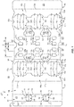
- Fig. 1 shows a plan view of an exterior side 101 of a blank 103 used to form a carrier 105 ( Fig. 7 ) in accordance with a first exemplary embodiment of the disclosure.
- the carrier 105 can be sized to contain or support six containers, with three containers CA1, CA2, CA3 being attached to a front portion 106 of the carrier 105 and three containers CB1, CB2, CB3 being attached to a back portion 108 of the carrier 105.
- the containers CA1, CA2, CA3, CB1, CB2, CB3 can be beverage cans, or could be any other suitable type and size of container without departing from the disclosure.
- the carrier 105 can be sized and shaped to hold more or less than six containers.
- the front portion 106 and the back portion 108 of the carrier 105 each have three containers, and in other embodiments, the front portion 106 and the back portion 108 of the carrier 105 can carry more or less than three containers without departing from the disclosure.
- the carrier 105 can be provided together with one or more containers as a package 110 ( Fig. 7 ).
- the blank 103 has a longitudinal axis L1 and a lateral axis L2.
- the blank 103 has a front portion 107 for forming the front portion 106 of the carrier 105, and a back portion 109 for forming the back portion 108 of the carrier 105.
- the front portion 107 and the back portion 109 of the blank 103 are foldably connected at a lateral fold line 112 that forms a lateral centerline CL of the blank 103, as shown.
- the blank 103 is at least partially formed into the carrier 105 by folding the blank 103 at the fold line 112 along the centerline CL so that the front portion 107 and the back portion 109 of the blank 103 are overlapped in at least partial face-to-face contact.
- the front portion 107 of the blank 103 comprises a front central panel 125a having a first front row RF1 of laterally spaced adhesive or glue openings 127a, and a second front row RF2 of the laterally spaced adhesive or glue openings 127a.
- the top edges of the respective glue openings 127a of the first row RF1 are spaced a longitudinal distance D1 apart from the fold line 112 that is less than a longitudinal distance D2 that the top edges of the respective glue openings 127a of the second row RF2 are spaced apart from the fold line 112.
- a front container retention panel or front attachment panel 131a is foldably connected to the front central panel 125a at a lateral fold line 133a, and includes a container retention portion 135a that is at least partially defined between a pair of longitudinally-spaced lateral fold lines 137a, 139a (broadly, respective "second fold line") that are each interrupted by respective pairs of longitudinally-spaced cuts 141a that can each include one or more curved and/or angled portions.
- the longitudinally-spaced cuts 141a define container retention tabs 148a that extend outwardly from the container retention portion 135a.
- respective oblique cuts 143a, 145a extend outwardly from each respective cut 141a to define a plurality of reconfigurable edges of the front attachment panel 131a that face the respective container retention tabs 148a.
- an interior marginal portion 136a of the attachment panel 131a is defined between the fold lines 137a, 133a, and an exterior marginal portion 138a of the attachment panel 131a is defined between the fold line 139a and a lateral fold line 171a.
- the blank 103 can include a pair of handle openings 130a that interrupt the fold line 133a and that extend from a portion of the front central panel 125a into a portion of the front attachment panel 131a.
- the handle openings 130a can include a longitudinal section 132a extending parallel to the longitudinal axis L1 and a pair of lateral sections 134a that intersect and diverge orthogonally away from the longitudinal section 132a in substantial parallel relation with the lateral axis L2.
- the divergent sections 132a, 134a of the handle opening 130a are in communication with one another.
- the sections 132a, 134a of the handle opening 130a provide multiple engagement surfaces at which a consumer can grasp the carrier 105, in different orientations.
- a reinforcement flap 136a is foldably connected to the respective attachment panel 131a at a respective curved fold line 140a, and extends into the respective longitudinal section 132a.
- the carrier 105 can have a different arrangement of handle features, or can be devoid of handle features, without departing from the disclosure.
- the blank 103 additionally includes a bevel or front side panel 169a that is foldably connected to the front attachment panel 131a at the lateral fold line 171a, and a top panel 173 that is foldably connected to the front side panel 169a at a lateral fold line 175a.
- the top panel 173, as shown, includes additional handle features (broadly, “first handle feature” and “second handle feature”) that each include a pair of opposed curved cuts 177, 179 and a longitudinal cut 181 extending from the curved cut 177 to the curved cut 179 to define a pair of handle flaps 183, 185.
- a pair of longitudinal lines of weakening 187, 189 and a pair of lateral lines of weakening 190, 191 extend along a portion of each flap 183, 185 so as to provide an at least partially reconfigurable arrangement, as described further herein.
- one or more of the lines of weakening 187, 189, 190, 191 can be a surface feature such as an emboss or deboss feature.
- Handle features of the carrier 205 include the handle features in the top panel 173, and can also include the handle openings 130a, 130b.
- the carrier 105 can have a different arrangement of handle features, or can be devoid of handle features, without departing from the disclosure.
- the top panel 173 additionally includes a pair of laterally-spaced longitudinal fold lines 193, 195 (broadly, "first fold line” and “second fold line”, respectively) that define a central portion 197 therebetween, and which further define a first marginal portion 199 of the top panel 173 defined between the fold lines 175a, 193, and a second marginal portion 201 of the top panel 173 defined between the fold line 195 and a lateral free edge of the top panel 173.
- the first marginal portion 199 of the top panel 173 is defined between the fold line 193 and the front side panel 169a.
- the central portion 197 of the top panel 173 is positioned to generally overlap and align with respective portions of the container retention portion 135a of the front attachment panel 131a and a container retention portion 135b of a back attachment panel 131b, the first marginal portion 199 of the top panel 173 is positioned to generally align with an exterior marginal portion 138b of the back attachment panel 131b, and the second marginal portion 201 of the top panel 173 is positioned to generally align with the exterior marginal portion 138a of the front attachment panel 131a.
- the back portion 109 of the blank 103 includes a back central panel 125b and the back container retention panel or back attachment panel 131b having associated features that are generally a mirror-image of the corresponding panels and flaps of the front portion 107 of the blank 103.
- Corresponding components e.g., panels, flaps, fold lines, cuts, etc.
- corresponding reference numbers that differ by the "a” or "b" suffix, with the "a” components corresponding to the front portion 107 of the blank 103 and the "b” components corresponding to the back portion 109 of the blank 103.
- the back portion 109 of the blank 103 additionally includes a back side panel 169b foldably connected to the back attachment panel 131b at a lateral fold line 171b, and an attachment flap 203 foldably connected to the back side panel 169b at a lateral fold line 175b.
- a pair of generally U-shaped cuts 157 extend from the centerline CL and have a respective lateral portion that defines the top edge of respective glue openings 127b of a first back lateral row RB1 of laterally spaced glue openings 127b.
- the top edges of the respective glue openings 127b of the first lateral row RB1 of glue openings 127b are spaced a longitudinal distance D3 apart from the fold line 112 that is less than a longitudinal distance D4 that the top edges of respective glue openings 127b of a second back lateral row RB2 of glue openings 127b are spaced apart from the fold line 112.
- the blank 103 is provided with front rows RF1 and RF2 of laterally-spaced front glue openings 127a that are spaced respective longitudinal distances D1, D2 from the centerline CL, and back rows RB1 and RB2 of laterally-spaced back glue openings 127b that are spaced respective longitudinal distances D3, D4 from the centerline CL.
- the glue openings 127a, 127b have a longitudinally staggered arrangement such that D2 > D4 > D1 > D3.
- the arrangement of the glue openings 127a, 127b is such that, upon erection of the carrier 105, the glue openings 127a, 127b provide access to a respective plurality of surfaces of the respective central panels 125b, 125a upon which the respective containers CA1, CA2, CA3, CB1, CB2, CB3 can be attached to enhance retention and support of the containers CA1, CA2, CA3, CB1, CB2, CB3 by the carrier 105.
- any of the panels, flaps, fold lines, cuts, or other features could be otherwise shaped, arranged, and/or omitted from the blank 103 without departing from the disclosure.
- the blank 103 could be sized and/or shaped to accommodate more or less than four containers without departing from this disclosure.
- an interior surface or underside of the blank 103 can be placed atop the containers CA1, CA2, CA3, CB1, CB2, CB3 such that the container retention portion 135a of the front attachment panel 131a overlies the containers CA1, CA2, CA3 and such that the container retention portion 135b of the back attachment panel 131b overlies the containers CB1, CB2, CB3.
- Further downward positioning of the attachment panels 131a, 131b over the plurality of containers CA1, CA2, CA3, CB1, CB2, CB3 can activate the respective container retention portions 135a, 135b to engage respective containers.
- the container retention portion 135a can at least partially separate from the remainder of the front attachment panel 131a at the cuts 141a.
- upper or top portions T of the respective containers CA1, CA2, CA3 can extend at least partially through respective openings formed by the respective cuts 141a such that the container retention tabs 148a can engage, for example, a recessed portion of a rim or other top structure of the respective container CA1, CA2, CA3, and such that a plurality of reconfigurable edges of the marginal portions 136a, 138a can engage, for example, a rolled rim edge or other top structure of the respective container CA1, CA2, CA3.
- Such reconfiguration of the corresponding portions of the back attachment panel 131b can occur as the back attachment panel 131b is lowed or urged downwardly onto the containers CB1, CB2, CB3.
- the marginal portions 136a, 138a of the attachment panel 131a can fold at least partially downwardly at the respective fold lines 137a, 139a in such a configuration, and, similarly, the marginal portions 136b, 138b of the attachment panel 131b can fold at least partially downwardly at the respective fold lines 137b, 139b.
- the front central panel 125a and the back central panel 125b can be folded at the fold line 112 such that the front central panel 125a and the back central panel 125b are brought into at least partial face-to-face contact in the direction of the arrows A1, A2 to be positioned between respective adjacent containers and such that the respective glue openings 127a, 127b are positioned so as to be laterally aligned but longitudinally offset due to the different relative spacing of the respective rows RF1, RF2 of the front glue openings 127a and the respective rows RB1, RB2 of the back glue openings 127b away from the fold line 112 as described above.
- the central panels 125a, 125b are arranged such that a portion of the front central panel 125a overlaps each of the glue openings 127b and a portion of the back central panel 125b overlaps each of the glue openings 127a to provide communication between the central panels 125a, 125b and respective surfaces upon which the respective containers CA1, CA2, CA3, CB1, CB2, CB3 can be adhered or otherwise attached, as described further herein.
- Such rearrangement of the central panels 125a, 125b can also cause the respective central panels 125a, 125b to be folded downwardly relative to the respective attachment panels 131a, 131b at the respective fold lines 133a, 133b.
- an adhesive glue G can be provided to adhere the containers CA1, CA2, CA3 to respective portions of the central panel 125b exposed through the respective glue openings 127a, and the glue G can be provided to adhere the containers CB1, CB2, CB3 to respective portions of the central panel 125a exposed through the respective glue openings 127b.
- the arrangement of multiple rows of respective glue openings 127a, 127b provides multiple points of attachment of each respective container to the respective opposite central panel 125a, 125b such that each container is provided with a robust attachment to a respective central panel 125a, 125b.
- the attachment of the containers CA1, CA2, CA3, and containers CB1, CB2, CB3 to the respective central panel 125a, 125b can provide retention and support of the respective containers, e.g., such that the containers do not detach from the carrier 105 under their own weight, in addition to or alternative to the container retention and support provided by the respective container retention portions 135a, 135b.
- one or more of the containers CA1, CA2, CA3, CB1, CB2, CB3 can be attached to a respective central panel 125a, 125b with glue G, without additional retention and support provided by a container retention portion as described above.
- the glue G described herein can be, for example, a hot melt adhesive, a high tack glue, an epoxy, a polymeric cement, etc., or combinations thereof.
- the glue G can have a different arrangement without departing from the disclosure.
- the glue G can be applied to one or more portions of the exterior surface of the blank 103/carrier 105.
- Such enhanced attachment of the respective containers to the respective central panels 125a, 125b with the glue G can also provide enhanced integrity to the carrier 105, e.g., by providing opposing adhesive forces on the respective central panels 125a, 125b such that the central panels 125a, 125b are compressed therebetween.
- the containers CA1, CA2, CA3 can at least partially pull the portions of the back central panel 125b to which they are attached through the respective glue openings 127a toward the front central panel 125a under the at least partial weight of the containers CA1, CA2, CA3.
- Respective portions of the front central panel 125a can be pulled toward the back central panel 125b through the respective glue openings 127b by the containers CB1, CB2, CB3 in a similar manner.
- the front side panel 169a can be folded upwardly at the fold line 171a, for example, to be at an oblique arrangement relative to the containers CA1, CA2, CB1, CB2, CB3 and the top panel 173 can be folded at the fold line 175a generally in the direction of the arrow A3 into at least partial face-to-face contact with at least a portion of the attachment panels 131a, 131b.
- the back side panel 169b can be folded upwardly at the fold line 171b into an oblique arrangement with the containers CA1, CA2, CA3, CB1, CB2, CB3 and the attachment flap 203 can be folded at the fold line 175b generally in the direction of the arrow A4 into at least partial face-to-face contact with the top panel 173 and/or the attachment panel 131b.
- Such an arrangement can be maintained with an adhesive such as glue.
- the respective handle flaps 183, 185 can be at least partially separated from the top panel 173 at the respective cuts 177, 179, and from each other at the respective cuts 181, and folded or flexed downwardly into an interior portion of the carrier 105/package 110.
- the handle openings 130a, 130b provide clearance for the handle flaps 183, 185 to extend downwardly in such an arrangement.
- one or both of the handle flaps 183, 185 can be provided with a reconfigurable arrangement, for example, so as to contour or angle against one or more of the respective containers CA1, CA2, CA3, CB1, CB2, CB3, e.g., such that at least a central portion of the respective handle flaps 183, 185 can be positioned between adjacent containers.
- marginal portions of the respective handle flaps 183, 185 can at least partially wrap around or surround a consumer's finger, for example, to minimize or prevent contact of the consumer's finger with edges or corners of the carrier 105/package 110 and/or the respective containers.
- the divergent nature of the respective longitudinal sections 132a, 132b and the respective lateral sections 134a, 134b of the respective handle openings 130a, 130b allows a consumer multiple edges and surfaces by which to engage and lift the carrier 105 such that the consumer can engage the carrier from multiple orientations, e.g., a lateral orientation or a longitudinal orientation, or orientations therebetween.
- the respective reinforcement flaps 136a, 136b can at least partially fold downwardly at the respective curved fold lines 138a, 138b to provide additional reinforcing structure between a customer's fingers and the respective attachment panel 131a, 131b, e.g., in a three-ply configuration.
- FIG. 8-10 an at least partial reconfiguration of the carrier 105 to facilitate removal of one or more of the containers CA1, CA2, CA3, CB1, CB2, CB3 will be described in accordance with an exemplary embodiment of the disclosure.
- first marginal portion 199 and the second marginal portion 201 of the top panel 173 can be folded at least partially upwardly at the respective fold lines 193, 195.
- Upward movement of the first marginal portion 199 can carry the front panel 169a and the exterior marginal portion 138a of the front attachment panel 131a therewith such that the first marginal portion 199, the front panel 169a, and the exterior marginal portion 138a can together form an articulable access feature 205 (broadly, "first access feature") that provides at least partial access to the containers CA1, CA2, CA3 in the front portion 106 of the carrier 105.
- the second marginal portion 201 of the top panel 173, the attachment flap 203 underlapped on the marginal portion 201, the back panel 169b, and the exterior marginal portion 138a can together form an articulable access feature 207 (broadly, "second access feature") that provides at least partial access to the containers CB1, CB2, CB3 in the back portion 108 of the carrier 105.
- second access feature articulable access feature
- the access feature 205 can be grasped by a customer, for example, by curling his or her fingers around portions of the first marginal portion 199 of the top panel 173, the front panel 169a, and/or the exterior marginal portion 138a of the attachment panel 131a, and lifting upwardly such that these panels/portions articulate to fold at least partially at the aligned fold lines 193, 139a in the respective top panel 173 and attachment panel 131a.
- the fold lines 193, 139a can be positioned in an offset relationship.
- Such movement of the access feature 205 can cause at least partial disengagement of one or more of the containers CA1, CA2, CA3 from the attachment panel 131a, for example, by withdrawing the top portion T of a respective container through an opening formed by a respective cut 141a along the respective attachment panel 131a.
- the access feature 207 can be grasped by a customer by curling his or her fingers around portions of the second marginal portion 201 of the top panel 173, the back panel 169b, and/or the exterior marginal portion 138a and lifting upwardly at the aligned fold lines 195, 139b in the respective top panel 173 and attachment panel 131a to provide access to the containers CB 1, CB2, CB3 in the back portion 108 of the carrier 105.
- Such movement of the access feature 207 can cause at least partial disengagement of one or more of the containers CB1, CB2, CB3 from the attachment panel 131b as described above with respect to the containers CA1, CA2, CA3.
- the fold lines 195, 139b can be positioned in an offset relationship.
- the access features 205, 207 are each reconfigurable/positionable between a first configuration/position, in which one or both of the marginal portions 199, 201 of the top panel 173 are generally perpendicular to the central panels 125a, 125b, and a second configuration/position, in which one or both of the marginal portions 199, 201 of the top panel 173 are generally raised or upright relative to the central panels 125a, 125b, e.g., such that the marginal portions 199, 201 are parallel with or obliquely-disposed relative to the central panels 125a, 125b, for example, to allow access to the containers.
- the respective marginal portions 138a, 138b of the respective attachment panels 135a, 135b can also be generally raised or upright relative to the central panels 125a, 125b.
- the respective marginal portions 138a, 138b of the respective attachment panels 135a, 135b can be considered to be generally perpendicular to the central panels 125a, 125b when the access features 205, 207 are in the first configuration/position.
- the access features 205, 207 can each be reconfigured/positioned from the second configuration/position by reversing the movement of the access features 205, 207 described above.
- the access features 205, 207 can be folded at least partially downwardly at the respective fold lines 193, 139a and fold lines 195, 139b toward a generally perpendicular arrangement relative to the central panels 125a, 125b.
- Such movement of the access features 205, 207 can cause at least partial re-engagement of one or more of the containers CA1, CA2, CA3 and CB1, CB2, CB3 with the respective attachment panels 131a, 131b as described above.
- a respective container CA1, CA2, CA3, CB1, CB2, CB3 can be further removed from the carrier 105 by peeling the respective container away from the respective central panel 125a, 125b. Peeling or pulling the containers CA1, CA2, CA3, CB1, CB2, CB3 away from a respective central panel 125a, 125b can involve pulling the respective container with a force sufficient to overcome the adhesive bond of the respective container and the respective central panel 125a, 125b provided by the glue G.
- the glue G can be selected so as to remain on a respective central panel 125a, 125b, e.g., such that substantially little or no glue G remains on the container as it is removed.
- One or more of the containers CA1, CA2, CA3, CB1, CB2, CB3 in one embodiment, can be reattached to a respective central panel 125a, 125b following therefrom by pressing the container against a respective region of glue G.
- the central panels 125a, 125b can be devoid of glue openings such that the respective containers CA1, CA2, CA3 and CB1, CB2, CB3 are adhered only to the respective central panel 125a, 125b.
- glue G can be provided both on portions of the respective central panels 125a, 125b exposed through the respective glue openings 127b, 127a as well as portions of the respective central panels 125a, 125b adjacent the respective glue openings 127a, 127b such that each container CA1, CA2, CA3, CB1, CB2, CB3 can be adhered to portions of both central panels 125a, 125b.
- the carrier 105/package 110 described above has a compact structure that can, for example, provide materials savings and waste reduction. Additionally, the arrangement of the glue G among the containers CA1, CA2, CA3, CB1, CB2, CB3 as well as the central panels 125a, 125b provides multiple points of attachment that results in a robust structure for holding and carrying the containers CA1, CA2, CA3, CB1, CB2, CB3.
- the exposure of one or more portions of the containers CA1, CA2, CA3 CB1, CB2, CB3 on exterior portions of the carrier 105/package 110 provides a consumer with a clear view of labeling or surface graphics associated with the containers CA1, CA2, CA3, CB1, CB2, CB3, as well as providing convenient access to remove one or more of the containers CA1, CA2, CA3, CB1, CB2, CB3 from the carrier 105/package 110.
- a blank 203 for forming a carrier 205 according to a second exemplary embodiment of the disclosure is illustrated.
- the blank 203 and the carrier 205 can have one or more features that are similar to those of the blank 103 and the carrier 105 of the first exemplary embodiment, and like or similar reference numbers refer to like or similar features.
- the attachment panels 131a, 131b of the blank 203 are each provided with a respective three laterally spaced cuts 141a, 141b such that the carrier 205 is sized and configured to support and retain six containers, with three containers CA1, CA2, CA3 in a front portion 206 of the carrier 205 and three containers CB1, CB2, CB3 in a back portion 208 of the carrier 205.
- the U-shaped cuts 157 interrupt the fold line 112 to define respective tabs 159 extending away from the centerline CL.
- the tabs 159 can separate from the surrounding material of the central panel 125b at the respective cuts 157 to expose a pair of glue openings 127b of the first back row RB1.
- the blank may be constructed from paperboard having a caliper so that it is heavier and more rigid than ordinary paper.
- the blank can also be constructed of other materials, such as cardboard, or any other material having properties suitable for enabling the carrier to function at least generally as described above.
- the blank can be coated with, for example, a clay coating.
- the clay coating may then be printed over with product, advertising, and other information or images.
- the blanks may then be coated with a varnish to protect information printed on the blanks.
- the blanks may also be coated with, for example, a moisture barrier layer, on either or both sides of the blanks.
- the blanks can also be laminated to or coated with one or more sheet-like materials at selected panels or panel sections.
- a line of weakening can include one or more of tear lines, cut lines, etc.
- a tear line can include: a slit that extends partially into the material along the desired line of weakness, and/or a series of spaced apart slits that extend partially into and/or completely through the material along the desired line of weakness, or various combinations of these features.
- one type tear line is in the form of a series of spaced apart slits that extend completely through the material, with adjacent slits being spaced apart slightly so that a nick (e.g., a small somewhat bridging-like piece of the material) is defined between the adjacent slits for typically temporarily connecting the material across the tear line.
- the nicks are broken during tearing along the tear line.
- the nicks typically are a relatively small percentage of the tear line, and alternatively the nicks can be omitted from or torn in a tear line such that the tear line is a continuous cut line. That is, it is within the scope of the present disclosure for each of the tear lines to be replaced with a continuous slit, or the like.
- a cut line can be a continuous slit or could be wider than a slit without departing from the present disclosure.
- a fold line can be any substantially linear, although not necessarily straight, form of weakening that facilitates folding therealong. More specifically, but not for the purpose of narrowing the scope of the present disclosure, fold lines include: a score line, such as lines formed with a blunt scoring knife, or the like, which creates a crushed or depressed portion in the material along the desired line of weakness; a cut that extends partially into a material along the desired line of weakness, and/or a series of cuts that extend partially into and/or completely through the material along the desired line of weakness; and various combinations of these features. In situations where cutting is used to create a fold line, typically the cutting will not be overly extensive in a manner that might cause a reasonable user to incorrectly consider the fold line to be a tear line.
- the above embodiments may be described as having one or more panels adhered together by glue during erection of the carrier embodiments.
- glue is intended to encompass all manner of adhesives commonly used to secure carrier panels in place.
Landscapes
- Engineering & Computer Science (AREA)
- Mechanical Engineering (AREA)
- Packages (AREA)
- Details Of Rigid Or Semi-Rigid Containers (AREA)
- Auxiliary Devices For And Details Of Packaging Control (AREA)
Abstract
Description
- This application is a continuation-in-part of
U.S. Patent Application No. 16/426,066, filed on May 30, 2019 U.S. Provisional Patent Application No. 62/779,689, filed on December 14, 2018 U.S. Provisional Patent Application No. 62/783,752, filed on December 21, 2018 U.S. Provisional Patent Application No. 62/796,830, filed on January 25, 2019 U.S. Provisional Patent Application No. 62/797,585, filed on January 28, 2019 U.S. Provisional Patent Application No. 62/810,015, filed on February 25, 2019 U.S. Provisional Patent Application No. 62/814,412, filed on March 6, 2019 U.S. Provisional Patent Application No. 62/817,120, filed on March 12, 2019 U.S. Provisional Patent Application No. 62/841,449, filed on May 1, 2019 - The disclosures of each of
U.S. Provisional Patent Application No. 62/779,689, filed on December 14, 2018 U.S. Provisional Patent Application No. 62/783,752, filed on December 21, 2018 U.S. Provisional Patent Application No. 62/796,830, filed on January 25, 2019 U.S. Provisional Patent Application No. 62/797,585, filed on January 28, 2019 U.S. Provisional Patent Application No. 62/810,015, filed on February 25, 2019 U.S. Provisional Patent Application No. 62/814,412, filed on March 6, 2019 U.S. Provisional Patent Application No. 62/817,120, filed on March 12, 2019 U.S. Provisional Patent Application No. 62/841,449, filed on May 1, 2019 U.S. Patent Application No. 16/426,050, filed on May 30, 2019 U.S. Patent Application No. 16/426,057, filed on May 30, 2019 U.S. Patent Application No. 16/426,060, filed on May 30, 2019 U.S. Patent Application No. 16/426,063, filed on May 30, 2019 U.S. Patent Application No. 16/426,066, filed on May 30, 2019 U.S. Design Patent Application No. 29/692,992, filed on May 30, 2019 U.S. Design Patent Application No. 29/692,993, filed on May 30, 2019 U.S. Design Patent Application No. 29/692,994, filed on May 30, 2019 U.S. Design Patent Application No. 29/692,996, filed on May 30, 2019 U.S. Design Patent Application No. 29/692,997 , are hereby incorporated by reference for all purposes as if presented herein in their entirety. - The present disclosure generally relates to cartons or carriers for holding, displaying, and/or transporting containers.
- According to one aspect of the disclosure, a carrier for holding a plurality of containers comprises a plurality of panels comprising a top panel, at least one central panel, and at least one attachment panel configured to receive a portion of one or more containers of the plurality of containers. The at least one central panel is for being positioned between and attached to adjacent containers of the plurality of containers. The carrier further comprises at least one access feature that is positionable for allowing access to at least one container of the plurality of containers, the at least one access feature comprises a marginal portion of the top panel and a marginal portion of the at least one attachment panel.
- According to another aspect of the disclosure, a blank for forming a carrier for holding a plurality of containers comprises a plurality of panels comprising a top panel, at least one central panel, and at least one attachment panel, and at least one access feature comprising a marginal portion of the top panel and a marginal portion of the at least one attachment panel. The at least one access feature is for being positionable for allowing access to at least one container of the plurality of containers when the carrier is formed from the blank, and the at least one central panel is for being positioned between and attached to adjacent containers of the plurality of containers when the carrier formed from the blank.
- According to another aspect of the disclosure, a method of forming a carrier for holding a plurality of containers, the method comprises obtaining a blank comprising a plurality of panels comprising a top panel, at least one central panel, and at least one attachment panel, and at least one access feature comprising a marginal portion of the top panel and a marginal portion of the at least one attachment panel. The method further comprises folding the plurality of panels such that the at least one central panel is positioned between adjacent containers of the plurality of containers, and attaching at least one container of the plurality of panels to the at least one central panel, the at least one access feature is positionable for allowing access to at least one container of the plurality of containers.
- According to another aspect of the disclosure, a package comprises a plurality of containers and a carrier for holding the plurality of containers. The carrier comprises a plurality of panels comprising a top panel, at least one central panel, and at least one attachment panel receiving a portion of one or more containers of the plurality of containers, the at least one central panel is positioned between and attached to adjacent containers of the plurality of containers. The carrier further comprises at least one access feature that is positionable for allowing access to at least one container of the plurality of containers, the at least one access feature comprises a marginal portion of the top panel and a marginal portion of the at least one attachment panel.
- Those skilled in the art will appreciate the above stated advantages and other advantages and benefits of various additional embodiments reading the following detailed description of the embodiments with reference to the below-listed drawing figures. It is within the scope of the present disclosure that the above-discussed aspects be provided both individually and in various combinations.
- According to common practice, the various features of the drawings discussed below are not necessarily drawn to scale. Dimensions of various features and elements in the drawings may be expanded or reduced to more clearly illustrate the embodiments of the disclosure.
-
Fig. 1 is a plan view of an outer surface of a blank for forming a carrier and package according to a first exemplary embodiment of the disclosure. -
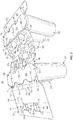
Fig. 2 is a perspective view of a partially folded configuration of a carrier formed from the blank ofFig. 1 according to the first exemplary embodiment. -
Fig. 3 is a perspective view of another partially folded configuration of a carrier formed from the blank ofFig. 1 according to the first exemplary embodiment. -
Fig. 4 is a front view of a carrier formed from the blank ofFig. 1 according to the first exemplary embodiment and having a container removed therefrom. -
Fig. 5 is a rear view of the carrier ofFig. 4 and having a container removed therefrom. -
Fig. 6 is a perspective view of another partially folded carrier formed from the blank ofFig. 1 according to the first exemplary embodiment. -
Fig. 7 is a perspective view of a package and carrier formed from the blank ofFig. 1 according to the first exemplary embodiment and having access features in a first configuration. -
Fig. 8 is a perspective view of the package and carrier ofFig. 7 , having access features in a second configuration. -
Fig. 9 is another perspective view of the package and carrier ofFig. 7 , having one access feature in a second configuration. -
Fig. 10 is a perspective view of the package and carrier ofFig. 9 and having a container removed therefrom. -
Fig. 11 is a plan view of an outer surface of a blank for forming a carrier and package according to a second exemplary embodiment of the disclosure. - Corresponding parts are designated by corresponding reference numbers throughout the drawings.
- The present disclosure generally relates to carriers, packages, constructs, sleeves, cartons, or the like, for holding and displaying containers such as jars, bottles, cans, etc. The containers can be used for packaging food and beverage products, for example. The containers can be made from materials suitable in composition for packaging the particular food or beverage item, and the materials include, but are not limited to, glass; plastics such as PET, LDPE, LLDPE, HDPE, PP, PS, PVC, EVOH, and Nylon; and the like; aluminum and/or other metals; or any combination thereof.
- Carriers according to the present disclosure can accommodate containers of numerous different shapes. For the purpose of illustration and not for the purpose of limiting the scope of the disclosure, the following detailed description describes beverage containers (e.g., aluminum cans) at least partially disposed within the carrier embodiments. In this specification, the terms "lower," "bottom," "upper," "top," "front," and "back" indicate orientations determined in relation to fully erected carriers.
- As described herein, carriers may be formed by multiple overlapping panels, end flaps, and/or other portions of blanks. Such panels, end flaps, and/or other portions of the blank can be designated in relative terms to one another, e.g., "first", "second", "third", etc., in sequential or non-sequential reference, without departing from the disclosure.
-
Fig. 1 shows a plan view of anexterior side 101 of a blank 103 used to form a carrier 105 (Fig. 7 ) in accordance with a first exemplary embodiment of the disclosure. Thecarrier 105 can be sized to contain or support six containers, with three containers CA1, CA2, CA3 being attached to afront portion 106 of thecarrier 105 and three containers CB1, CB2, CB3 being attached to aback portion 108 of thecarrier 105. In the illustrated embodiment, the containers CA1, CA2, CA3, CB1, CB2, CB3 can be beverage cans, or could be any other suitable type and size of container without departing from the disclosure. Thecarrier 105 can be sized and shaped to hold more or less than six containers. In one embodiment, thefront portion 106 and theback portion 108 of thecarrier 105 each have three containers, and in other embodiments, thefront portion 106 and theback portion 108 of thecarrier 105 can carry more or less than three containers without departing from the disclosure. Thecarrier 105 can be provided together with one or more containers as a package 110 (Fig. 7 ). - As shown in
Fig. 1 , the blank 103 has a longitudinal axis L1 and a lateral axis L2. The blank 103 has afront portion 107 for forming thefront portion 106 of thecarrier 105, and aback portion 109 for forming theback portion 108 of thecarrier 105. Thefront portion 107 and theback portion 109 of the blank 103 are foldably connected at alateral fold line 112 that forms a lateral centerline CL of the blank 103, as shown. As discussed further below, the blank 103 is at least partially formed into thecarrier 105 by folding the blank 103 at thefold line 112 along the centerline CL so that thefront portion 107 and theback portion 109 of the blank 103 are overlapped in at least partial face-to-face contact. - In the illustrated embodiment, the
front portion 107 of the blank 103 comprises a frontcentral panel 125a having a first front row RF1 of laterally spaced adhesive orglue openings 127a, and a second front row RF2 of the laterally spaced adhesive orglue openings 127a. The top edges of therespective glue openings 127a of the first row RF1 are spaced a longitudinal distance D1 apart from thefold line 112 that is less than a longitudinal distance D2 that the top edges of therespective glue openings 127a of the second row RF2 are spaced apart from thefold line 112. - A front container retention panel or
front attachment panel 131a is foldably connected to the frontcentral panel 125a at alateral fold line 133a, and includes acontainer retention portion 135a that is at least partially defined between a pair of longitudinally-spacedlateral fold lines spaced cuts 141a that can each include one or more curved and/or angled portions. As shown, the longitudinally-spaced cuts 141a definecontainer retention tabs 148a that extend outwardly from thecontainer retention portion 135a. As also shown, respectiveoblique cuts respective cut 141a to define a plurality of reconfigurable edges of thefront attachment panel 131a that face the respectivecontainer retention tabs 148a. - As shown, an interior
marginal portion 136a of theattachment panel 131a is defined between thefold lines marginal portion 138a of theattachment panel 131a is defined between thefold line 139a and alateral fold line 171a. - The blank 103 can include a pair of
handle openings 130a that interrupt thefold line 133a and that extend from a portion of the frontcentral panel 125a into a portion of thefront attachment panel 131a. As shown, thehandle openings 130a can include alongitudinal section 132a extending parallel to the longitudinal axis L1 and a pair oflateral sections 134a that intersect and diverge orthogonally away from thelongitudinal section 132a in substantial parallel relation with the lateral axis L2. In this regard, thedivergent sections sections carrier 105, in different orientations. As also shown, areinforcement flap 136a is foldably connected to therespective attachment panel 131a at a respectivecurved fold line 140a, and extends into the respectivelongitudinal section 132a. Thecarrier 105 can have a different arrangement of handle features, or can be devoid of handle features, without departing from the disclosure. - The blank 103 additionally includes a bevel or
front side panel 169a that is foldably connected to thefront attachment panel 131a at thelateral fold line 171a, and atop panel 173 that is foldably connected to thefront side panel 169a at alateral fold line 175a. Thetop panel 173, as shown, includes additional handle features (broadly, "first handle feature" and "second handle feature") that each include a pair of opposedcurved cuts longitudinal cut 181 extending from thecurved cut 177 to thecurved cut 179 to define a pair of handle flaps 183, 185. A pair of longitudinal lines of weakening 187, 189 and a pair of lateral lines of weakening 190, 191 extend along a portion of eachflap carrier 205 include the handle features in thetop panel 173, and can also include thehandle openings carrier 105 can have a different arrangement of handle features, or can be devoid of handle features, without departing from the disclosure. - Still referring to
Fig. 1 , thetop panel 173 additionally includes a pair of laterally-spacedlongitudinal fold lines 193, 195 (broadly, "first fold line" and "second fold line", respectively) that define acentral portion 197 therebetween, and which further define a firstmarginal portion 199 of thetop panel 173 defined between thefold lines marginal portion 201 of thetop panel 173 defined between thefold line 195 and a lateral free edge of thetop panel 173. In this regard, the firstmarginal portion 199 of thetop panel 173 is defined between thefold line 193 and thefront side panel 169a. - As described further herein, upon formation of the
carrier 105, thecentral portion 197 of thetop panel 173 is positioned to generally overlap and align with respective portions of thecontainer retention portion 135a of thefront attachment panel 131a and acontainer retention portion 135b of aback attachment panel 131b, the firstmarginal portion 199 of thetop panel 173 is positioned to generally align with an exteriormarginal portion 138b of theback attachment panel 131b, and the secondmarginal portion 201 of thetop panel 173 is positioned to generally align with the exteriormarginal portion 138a of thefront attachment panel 131a. - In the illustrated embodiment, the
back portion 109 of the blank 103 includes a backcentral panel 125b and the back container retention panel or backattachment panel 131b having associated features that are generally a mirror-image of the corresponding panels and flaps of thefront portion 107 of the blank 103. Corresponding components (e.g., panels, flaps, fold lines, cuts, etc.) have been designated by corresponding reference numbers that differ by the "a" or "b" suffix, with the "a" components corresponding to thefront portion 107 of the blank 103 and the "b" components corresponding to theback portion 109 of the blank 103. Theback portion 109 of the blank 103 additionally includes aback side panel 169b foldably connected to theback attachment panel 131b at alateral fold line 171b, and anattachment flap 203 foldably connected to theback side panel 169b at alateral fold line 175b. - As shown, a pair of generally
U-shaped cuts 157 extend from the centerline CL and have a respective lateral portion that defines the top edge ofrespective glue openings 127b of a first back lateral row RB1 of laterally spacedglue openings 127b. As shown, the top edges of therespective glue openings 127b of the first lateral row RB1 ofglue openings 127b are spaced a longitudinal distance D3 apart from thefold line 112 that is less than a longitudinal distance D4 that the top edges ofrespective glue openings 127b of a second back lateral row RB2 ofglue openings 127b are spaced apart from thefold line 112. - In this regard, the blank 103 is provided with front rows RF1 and RF2 of laterally-spaced
front glue openings 127a that are spaced respective longitudinal distances D1, D2 from the centerline CL, and back rows RB1 and RB2 of laterally-spacedback glue openings 127b that are spaced respective longitudinal distances D3, D4 from the centerline CL. Theglue openings carrier 105 from the blank 103, the longitudinal centerline CL/fold line 112 can form a bottom edge of thecentral panels - As described herein, the arrangement of the
glue openings carrier 105, theglue openings central panels carrier 105. - Any of the panels, flaps, fold lines, cuts, or other features could be otherwise shaped, arranged, and/or omitted from the blank 103 without departing from the disclosure. The blank 103 could be sized and/or shaped to accommodate more or less than four containers without departing from this disclosure.
- As shown in
Fig. 2 , an interior surface or underside of the blank 103 can be placed atop the containers CA1, CA2, CA3, CB1, CB2, CB3 such that thecontainer retention portion 135a of thefront attachment panel 131a overlies the containers CA1, CA2, CA3 and such that thecontainer retention portion 135b of theback attachment panel 131b overlies the containers CB1, CB2, CB3. Further downward positioning of theattachment panels container retention portions front attachment panel 131a is lowered or urged downwardly onto the containers CA1, CA2, CA3, thecontainer retention portion 135a can at least partially separate from the remainder of thefront attachment panel 131a at thecuts 141a. In such an arrangement, upper or top portions T of the respective containers CA1, CA2, CA3 can extend at least partially through respective openings formed by therespective cuts 141a such that thecontainer retention tabs 148a can engage, for example, a recessed portion of a rim or other top structure of the respective container CA1, CA2, CA3, and such that a plurality of reconfigurable edges of themarginal portions - Such reconfiguration of the corresponding portions of the
back attachment panel 131b can occur as theback attachment panel 131b is lowed or urged downwardly onto the containers CB1, CB2, CB3. During the above-described engagement of the respectivecontainer retention portions marginal portions attachment panel 131a can fold at least partially downwardly at therespective fold lines marginal portions attachment panel 131b can fold at least partially downwardly at therespective fold lines - Referring additionally to
Fig. 3 , the frontcentral panel 125a and the backcentral panel 125b can be folded at thefold line 112 such that the frontcentral panel 125a and the backcentral panel 125b are brought into at least partial face-to-face contact in the direction of the arrows A1, A2 to be positioned between respective adjacent containers and such that therespective glue openings front glue openings 127a and the respective rows RB1, RB2 of theback glue openings 127b away from thefold line 112 as described above. - In this regard, the
central panels central panel 125a overlaps each of theglue openings 127b and a portion of the backcentral panel 125b overlaps each of theglue openings 127a to provide communication between thecentral panels central panels central panels respective attachment panels respective fold lines - Referring to
Figs. 4 and5 , in which the respective containers CA3, CB1 are removed for clarity of illustration, an adhesive glue G can be provided to adhere the containers CA1, CA2, CA3 to respective portions of thecentral panel 125b exposed through therespective glue openings 127a, and the glue G can be provided to adhere the containers CB1, CB2, CB3 to respective portions of thecentral panel 125a exposed through therespective glue openings 127b. The arrangement of multiple rows ofrespective glue openings central panel central panel central panel carrier 105 under their own weight, in addition to or alternative to the container retention and support provided by the respectivecontainer retention portions central panel - The glue G described herein can be, for example, a hot melt adhesive, a high tack glue, an epoxy, a polymeric cement, etc., or combinations thereof. The glue G can have a different arrangement without departing from the disclosure. For example, in one embodiment, the glue G can be applied to one or more portions of the exterior surface of the blank 103/
carrier 105. - Such enhanced attachment of the respective containers to the respective
central panels carrier 105, e.g., by providing opposing adhesive forces on the respectivecentral panels central panels carrier 105 is lifted, the containers CA1, CA2, CA3 can at least partially pull the portions of the backcentral panel 125b to which they are attached through therespective glue openings 127a toward the frontcentral panel 125a under the at least partial weight of the containers CA1, CA2, CA3. Respective portions of the frontcentral panel 125a can be pulled toward the backcentral panel 125b through therespective glue openings 127b by the containers CB1, CB2, CB3 in a similar manner. - Referring to
Figs. 6 and7 , thefront side panel 169a can be folded upwardly at thefold line 171a, for example, to be at an oblique arrangement relative to the containers CA1, CA2, CB1, CB2, CB3 and thetop panel 173 can be folded at thefold line 175a generally in the direction of the arrow A3 into at least partial face-to-face contact with at least a portion of theattachment panels back side panel 169b can be folded upwardly at thefold line 171b into an oblique arrangement with the containers CA1, CA2, CA3, CB1, CB2, CB3 and theattachment flap 203 can be folded at thefold line 175b generally in the direction of the arrow A4 into at least partial face-to-face contact with thetop panel 173 and/or theattachment panel 131b. Such an arrangement can be maintained with an adhesive such as glue. - The respective handle flaps 183, 185 can be at least partially separated from the
top panel 173 at therespective cuts respective cuts 181, and folded or flexed downwardly into an interior portion of thecarrier 105/package 110. Thehandle openings - In one embodiment, marginal portions of the respective handle flaps 183, 185 can at least partially wrap around or surround a consumer's finger, for example, to minimize or prevent contact of the consumer's finger with edges or corners of the
carrier 105/package 110 and/or the respective containers. In addition, and as described above, the divergent nature of the respectivelongitudinal sections respective lateral sections respective handle openings carrier 105 such that the consumer can engage the carrier from multiple orientations, e.g., a lateral orientation or a longitudinal orientation, or orientations therebetween. - Should the handle
openings longitudinal sections respective reinforcement flaps curved fold lines respective attachment panel - Referring additionally to
Figs. 8-10 , an at least partial reconfiguration of thecarrier 105 to facilitate removal of one or more of the containers CA1, CA2, CA3, CB1, CB2, CB3 will be described in accordance with an exemplary embodiment of the disclosure. - As shown in
Figs. 7 and8 , one or both of the firstmarginal portion 199 and the secondmarginal portion 201 of thetop panel 173 can be folded at least partially upwardly at therespective fold lines marginal portion 199 can carry thefront panel 169a and the exteriormarginal portion 138a of thefront attachment panel 131a therewith such that the firstmarginal portion 199, thefront panel 169a, and the exteriormarginal portion 138a can together form an articulable access feature 205 (broadly, "first access feature") that provides at least partial access to the containers CA1, CA2, CA3 in thefront portion 106 of thecarrier 105. Similarly, the secondmarginal portion 201 of thetop panel 173, theattachment flap 203 underlapped on themarginal portion 201, theback panel 169b, and the exteriormarginal portion 138a can together form an articulable access feature 207 (broadly, "second access feature") that provides at least partial access to the containers CB1, CB2, CB3 in theback portion 108 of thecarrier 105. - For example, the
access feature 205 can be grasped by a customer, for example, by curling his or her fingers around portions of the firstmarginal portion 199 of thetop panel 173, thefront panel 169a, and/or the exteriormarginal portion 138a of theattachment panel 131a, and lifting upwardly such that these panels/portions articulate to fold at least partially at the alignedfold lines top panel 173 andattachment panel 131a. In one embodiment, thefold lines - Such movement of the
access feature 205 can cause at least partial disengagement of one or more of the containers CA1, CA2, CA3 from theattachment panel 131a, for example, by withdrawing the top portion T of a respective container through an opening formed by arespective cut 141a along therespective attachment panel 131a. - Similarly, the
access feature 207 can be grasped by a customer by curling his or her fingers around portions of the secondmarginal portion 201 of thetop panel 173, theback panel 169b, and/or the exteriormarginal portion 138a and lifting upwardly at the alignedfold lines top panel 173 andattachment panel 131a to provide access to the containers CB 1, CB2, CB3 in theback portion 108 of thecarrier 105. Such movement of theaccess feature 207 can cause at least partial disengagement of one or more of the containers CB1, CB2, CB3 from theattachment panel 131b as described above with respect to the containers CA1, CA2, CA3. In one embodiment, thefold lines - Accordingly, the access features 205, 207 are each reconfigurable/positionable between a first configuration/position, in which one or both of the
marginal portions top panel 173 are generally perpendicular to thecentral panels marginal portions top panel 173 are generally raised or upright relative to thecentral panels marginal portions central panels marginal portions respective attachment panels central panels - In one embodiment, the respective
marginal portions respective attachment panels central panels - It will be understood that the access features 205, 207 can each be reconfigured/positioned from the second configuration/position by reversing the movement of the access features 205, 207 described above. For example, the access features 205, 207 can be folded at least partially downwardly at the
respective fold lines lines central panels respective attachment panels - As shown in
Figs. 9 and10 , in which only thesecond access feature 207 is shown in the second configuration/position, a respective container CA1, CA2, CA3, CB1, CB2, CB3 can be further removed from thecarrier 105 by peeling the respective container away from the respectivecentral panel central panel central panel central panel - One or more of the containers CA1, CA2, CA3, CB1, CB2, CB3 in one embodiment, can be reattached to a respective
central panel - It will be understood that a different number of rows or arrangements of glue openings can be provided without departing from the disclosure, and that the central panels can be sized and configured to accommodate such arrangements. In one embodiment, the
central panels central panel central panels respective glue openings central panels respective glue openings central panels - The
carrier 105/package 110 described above has a compact structure that can, for example, provide materials savings and waste reduction. Additionally, the arrangement of the glue G among the containers CA1, CA2, CA3, CB1, CB2, CB3 as well as thecentral panels carrier 105/package 110 provides a consumer with a clear view of labeling or surface graphics associated with the containers CA1, CA2, CA3, CB1, CB2, CB3, as well as providing convenient access to remove one or more of the containers CA1, CA2, CA3, CB1, CB2, CB3 from thecarrier 105/package 110. - Referring additionally to
Fig. 11 , a blank 203 for forming acarrier 205 according to a second exemplary embodiment of the disclosure is illustrated. The blank 203 and thecarrier 205 can have one or more features that are similar to those of the blank 103 and thecarrier 105 of the first exemplary embodiment, and like or similar reference numbers refer to like or similar features. - As shown, the
attachment panels cuts carrier 205 is sized and configured to support and retain six containers, with three containers CA1, CA2, CA3 in a front portion 206 of thecarrier 205 and three containers CB1, CB2, CB3 in a back portion 208 of thecarrier 205. - As also shown, the
U-shaped cuts 157 interrupt thefold line 112 to definerespective tabs 159 extending away from the centerline CL. Upon formation of a carrier from the blank 203, thetabs 159 can separate from the surrounding material of thecentral panel 125b at therespective cuts 157 to expose a pair ofglue openings 127b of the first back row RB1. - It will be understood that the blanks and carriers described herein can be provided in different configurations without departing from the disclosure.
- In general, the blank may be constructed from paperboard having a caliper so that it is heavier and more rigid than ordinary paper. The blank can also be constructed of other materials, such as cardboard, or any other material having properties suitable for enabling the carrier to function at least generally as described above. The blank can be coated with, for example, a clay coating. The clay coating may then be printed over with product, advertising, and other information or images. The blanks may then be coated with a varnish to protect information printed on the blanks. The blanks may also be coated with, for example, a moisture barrier layer, on either or both sides of the blanks. The blanks can also be laminated to or coated with one or more sheet-like materials at selected panels or panel sections.
- As described herein, a line of weakening can include one or more of tear lines, cut lines, etc. As an example, a tear line can include: a slit that extends partially into the material along the desired line of weakness, and/or a series of spaced apart slits that extend partially into and/or completely through the material along the desired line of weakness, or various combinations of these features. As a more specific example, one type tear line is in the form of a series of spaced apart slits that extend completely through the material, with adjacent slits being spaced apart slightly so that a nick (e.g., a small somewhat bridging-like piece of the material) is defined between the adjacent slits for typically temporarily connecting the material across the tear line. The nicks are broken during tearing along the tear line. The nicks typically are a relatively small percentage of the tear line, and alternatively the nicks can be omitted from or torn in a tear line such that the tear line is a continuous cut line. That is, it is within the scope of the present disclosure for each of the tear lines to be replaced with a continuous slit, or the like. For example, a cut line can be a continuous slit or could be wider than a slit without departing from the present disclosure.
- In accordance with the exemplary embodiments, a fold line can be any substantially linear, although not necessarily straight, form of weakening that facilitates folding therealong. More specifically, but not for the purpose of narrowing the scope of the present disclosure, fold lines include: a score line, such as lines formed with a blunt scoring knife, or the like, which creates a crushed or depressed portion in the material along the desired line of weakness; a cut that extends partially into a material along the desired line of weakness, and/or a series of cuts that extend partially into and/or completely through the material along the desired line of weakness; and various combinations of these features. In situations where cutting is used to create a fold line, typically the cutting will not be overly extensive in a manner that might cause a reasonable user to incorrectly consider the fold line to be a tear line.
- The above embodiments may be described as having one or more panels adhered together by glue during erection of the carrier embodiments. The term "glue" is intended to encompass all manner of adhesives commonly used to secure carrier panels in place.
- The foregoing description of the disclosure illustrates and describes various exemplary embodiments. Various additions, modifications, changes, etc., could be made to the exemplary embodiments without departing from the spirit and scope of the disclosure. It is intended that all matter contained in the above description or shown in the accompanying drawings shall be interpreted as illustrative and not in a limiting sense. Additionally, the disclosure shows and describes only selected embodiments of the disclosure, but the disclosure is capable of use in various other combinations, modifications, and environments and is capable of changes or modifications within the scope of the inventive concept as expressed herein, commensurate with the above teachings, and/or within the skill or knowledge of the relevant art. Furthermore, certain features and characteristics of each embodiment may be selectively interchanged and applied to other illustrated and non-illustrated embodiments of the disclosure.
Claims (28)
- A carrier for holding a plurality of containers, the carrier comprising:a plurality of panels comprising a top panel, at least one central panel, and at least one attachment panel configured to receive a portion of one or more containers of the plurality of containers, the at least one central panel is for being positioned between and attached to adjacent containers of the plurality of containers; andat least one access feature that is positionable for allowing access to at least one container of the plurality of containers, the at least one access feature comprises a marginal portion of the top panel and a marginal portion of the at least one attachment panel.
- The carrier of claim 1, wherein the at least one central panel is for being adhered to adjacent containers of the plurality of containers.
- The carrier of claim 1, wherein the at least one access feature is reconfigurable between a first configuration in which the marginal portion of the top panel is generally perpendicular to the at least one central panel, and a second configuration in which the marginal portion of the top panel and the marginal portion of the at least one attachment panel are raised to allow access to at least one container of the plurality of containers.
- The carrier of claim 3, wherein the access feature further comprises a side panel foldably connected to the marginal portion of the top panel and the marginal portion of the at least one attachment panel and the marginal portion of the top panel overlaps the marginal portion of the at least one attachment panel.
- The carrier of claim 3, wherein the access feature further comprises a side panel foldably connected to the marginal portion of the top panel and the marginal portion of the at least one attachment panel and the marginal portion of the top panel is a first marginal portion of the top panel and the carrier further comprises a second marginal portion of the top panel, the at least one attachment panel is a front attachment panel and the carrier further comprises a back attachment panel, the at least one side panel is a front side panel and the carrier further comprises a back side panel foldably connected to the back attachment panel, the top panel comprises a central portion, the at least one access feature is a first access feature foldably connected to the central portion of the top panel at a first fold line, and the carrier further comprises a second access feature comprising the second marginal portion of the top panel and a marginal portion of the back attachment panel, the second access feature is foldably connected to the central portion of the top panel at a second fold line.
- The carrier of claim 5, wherein the at least one central panel is a front central panel foldably connected to the front attachment panel, and the carrier further comprises a back central panel in at least partial face-to-face contact with the front central panel and foldably connected to the back attachment panel.
- The carrier of claim 1, wherein the at least one central panel comprises a first row of openings and a second row of openings spaced apart from the first row of openings,
the first row of openings is spaced a first distance from a bottom edge of the at least one central panel, and the second row of openings is spaced a second distance from the bottom edge of the at least one central panel, the second distance is greater than the first distance. - The carrier of claim 7, wherein the at least one central panel is a front central panel, the plurality of panels further comprises a back central panel in face-to-face contact with the front central panel, the at least one attachment panel is a front attachment panel foldably connected to the front central panel, and the plurality of panels further comprises a back attachment panel foldably connected to the back central panel, the plurality of openings is a first plurality of openings in the front central panel, and the back central panel comprises a second plurality of openings such that the first plurality of openings are in communication with the back central panel and the second plurality of openings are in communication with the front central panel.
- The carrier of claim 1, wherein at least one of the at least one central panel and the at least one attachment panel includes at least one handle opening, the top panel comprises at least one handle feature, the at least one handle feature is aligned with the at least one handle opening.
- A blank for forming a carrier for holding a plurality of containers, the blank comprising:a plurality of panels comprising a top panel, at least one central panel, and at least one attachment panel, andat least one access feature comprising a marginal portion of the top panel and a marginal portion of the at least one attachment panel, the at least one access feature is for being positionable for allowing access to at least one container of the plurality of containers when the carrier is formed from the blank,the at least one central panel is for being positioned between and attached to adjacent containers of the plurality of containers when the carrier formed from the blank.
- The blank of claim 10, wherein the at least one central panel is for being adhered to adjacent containers of the plurality of containers.
- The blank of claim 10, wherein, when the carrier is formed from the blank, the at least one access feature is reconfigurable between a first configuration in which the marginal portion of the top panel is generally perpendicular to the at least one central panel, and a second configuration in which the marginal portion of the top panel and the marginal portion of the at least one attachment panel are raised to allow access to at least one container of the plurality of containers.
- The blank of claim 12, wherein the access feature further comprises a side panel foldably connected to the marginal portion of the top panel and the marginal portion of the at least one attachment panel, marginal portion of the top panel is a first marginal portion of the top panel and the carrier further comprises a second marginal portion of the top panel, the at least one attachment panel is a front attachment panel and the carrier further comprises a back attachment panel, the at least one side panel is a front side panel and the carrier further comprises a back side panel foldably connected to the back attachment panel, the top panel comprises a central portion, the at least one access feature is a first access feature foldably connected to the central portion of the top panel at a first fold line, and the carrier further comprises a second access feature comprising the second marginal portion of the top panel and a marginal portion of the back attachment panel, the second access feature is foldably connected to the central portion of the top panel at a second fold line.
- The blank of claim 13, wherein the at least one central panel is a front central panel foldably connected to the front attachment panel, and the carrier further comprises a back central panel foldably connected to the back attachment panel.
- The blank of claim 10, wherein the at least one central panel comprises a first row of openings and a second row of openings spaced apart from the first row of openings,
the first row of openings is spaced a first distance from a bottom edge of the at least one central panel, and the second row of openings is spaced a second distance from the bottom edge of the at least one central panel, the second distance is greater than the first distance. - The blank of claim 15, wherein the at least one central panel is a front central panel, the plurality of panels further comprises a back central panel, the at least one attachment panel is a front attachment panel foldably connected to the front central panel, and the plurality of panels further comprises a back attachment panel foldably connected to the back central panel, the plurality of openings is a first plurality of openings in the front central panel, and the back central panel comprises a second plurality of openings such that, when the carrier is formed from the blank, the first plurality of openings are in communication with the back central panel and the second plurality of openings are in communication with the front central panel.
- The blank of claim 10, wherein at least one of the at least one central panel and the at least one attachment panel includes at least one handle opening, the top panel comprises at least one handle feature for being aligned with the at least one handle opening when the carrier is formed from the blank.
- A method of forming a carrier for holding a plurality of containers, the method comprising:obtaining a blank comprising a plurality of panels comprising a top panel, at least one central panel, and at least one attachment panel, and at least one access feature comprising a marginal portion of the top panel and a marginal portion of the at least one attachment panel;folding the plurality of panels such that the at least one central panel is positioned between adjacent containers of the plurality of containers; andattaching at least one container of the plurality of panels to the at least one central panel, the at least one access feature is positionable for allowing access to at least one container of the plurality of containers.
- The method of claim 18, wherein the at least one central panel is for being adhered to adjacent containers of the plurality of containers.
- The method of claim 18, wherein the at least one access feature is reconfigurable between a first configuration in which the marginal portion of the top panel is generally perpendicular to the at least one central panel, and a second configuration in which the marginal portion of the top panel and the marginal portion of the at least one attachment panel are raised to allow access to at least one container of the plurality of containers.
- The method of claim 20, wherein the access feature further comprises a side panel foldably connected to the marginal portion of the top panel and the marginal portion of the at least one attachment panel, and the marginal portion of the top panel overlaps the marginal portion of the at least one attachment panel.
- The method of claim 20, wherein the access feature further comprises a side panel foldably connected to the marginal portion of the top panel and the marginal portion of the at least one attachment panel, and the marginal portion of the top panel is a first marginal portion of the top panel and the carrier further comprises a second marginal portion of the top panel, the at least one attachment panel is a front attachment panel and the carrier further comprises a back attachment panel, the at least one side panel is a front side panel and the carrier further comprises a back side panel foldably connected to the back attachment panel, the top panel comprises a central portion, the at least one access feature is a first access feature foldably connected to the central portion of the top panel at a first fold line, and the carrier further comprises a second access feature comprising the second marginal portion of the top panel and a marginal portion of the back attachment panel, the second access feature is foldably connected to the central portion of the top panel at a second fold line.
- The method of claim 22, wherein the at least one central panel is a front central panel foldably connected to the front attachment panel, and the carrier further comprises a back central panel in at least partial face-to-face contact with the front central panel and foldably connected to the back attachment panel.
- The method of claim 18, wherein the at least one central panel comprises a a first row of openings and a second row of openings spaced apart from the first row of openings, the first row of openings is spaced a first distance from a bottom edge of the at least one central panel, and the second row of openings is spaced a second distance from the bottom edge of the at least one central panel, the second distance is greater than the first distance.
- The method of claim 24, wherein the at least one central panel is a front central panel, the plurality of panels further comprises a back central panel in face-to-face contact with the front central panel, the at least one attachment panel is a front attachment panel foldably connected to the front central panel, and the plurality of panels further comprises a back attachment panel foldably connected to the back central panel, the plurality of openings is a first plurality of openings in the front central panel, and the back central panel comprises a second plurality of openings such that the first plurality of openings are in communication with the back central panel and the second plurality of openings are in communication with the front central panel.
- The method of claim 18, wherein at least one of the at least one central panel and the at least one attachment panel includes at least one handle opening, the top panel comprises at least one handle feature, the at least one handle feature is aligned with the at least one handle opening.
- A package comprising: a plurality of containers; and the carrier of claim 1 holding the plurality of container.
- The package of claim 27, wherein the at least one central panel is adhered to adjacent containers of the plurality of containers.
Applications Claiming Priority (1)
| Application Number | Priority Date | Filing Date | Title |
|---|---|---|---|
| US16/598,282 US11261013B2 (en) | 2018-12-14 | 2019-10-10 | Carrier for containers |
Publications (3)
| Publication Number | Publication Date |
|---|---|
| EP3808677A1 true EP3808677A1 (en) | 2021-04-21 |
| EP3808677B1 EP3808677B1 (en) | 2024-12-04 |
| EP3808677C0 EP3808677C0 (en) | 2024-12-04 |
Family
ID=72801367
Family Applications (1)
| Application Number | Title | Priority Date | Filing Date |
|---|---|---|---|
| EP20200533.6A Active EP3808677B1 (en) | 2019-10-10 | 2020-10-07 | Carrier for containers |
Country Status (12)
| Country | Link |
|---|---|
| EP (1) | EP3808677B1 (en) |
| JP (1) | JP7612680B2 (en) |
| KR (1) | KR102917307B1 (en) |
| CN (1) | CN114502481B (en) |
| AU (1) | AU2020364363B2 (en) |
| BR (1) | BR112022005754A2 (en) |
| CA (1) | CA3156282C (en) |
| ES (1) | ES2997084T3 (en) |
| MX (1) | MX2022004256A (en) |
| PH (1) | PH12022550825A1 (en) |
| PL (1) | PL3808677T3 (en) |
| WO (1) | WO2021071764A1 (en) |
Citations (8)
| Publication number | Priority date | Publication date | Assignee | Title |
|---|---|---|---|---|
| US3001647A (en) * | 1958-10-22 | 1961-09-26 | Liss Jack | Package |
| US3245711A (en) * | 1964-01-16 | 1966-04-12 | Kenneth R Dantoin | Paperboard can carrier |
| US3281180A (en) * | 1964-03-24 | 1966-10-25 | Joseph C Spery | Container carrier |
| GB1256684A (en) * | 1969-02-21 | 1971-12-15 | ||
| US5282348A (en) * | 1992-06-16 | 1994-02-01 | Riverwood International Corporation | Clip-type article carrier and method of manufacture |
| US5503267A (en) * | 1995-04-11 | 1996-04-02 | Riverwood International Corporation | Can clip carrier with glue flaps |
| US20040226833A1 (en) * | 2001-08-17 | 2004-11-18 | Jean-Yves Daniel | Carton with top retaining structure and blank therefor |
| WO2012075374A2 (en) * | 2010-12-03 | 2012-06-07 | Graphic Packaging International, Inc. | Package for containers |
Family Cites Families (16)
| Publication number | Priority date | Publication date | Assignee | Title |
|---|---|---|---|---|
| US3046711A (en) * | 1960-12-08 | 1962-07-31 | Grace W R & Co | Multiple can carrier and sanitary seal |
| US3701416A (en) * | 1969-05-30 | 1972-10-31 | Frank D Lawrence | Holders for containers |
| US3612266A (en) * | 1969-11-06 | 1971-10-12 | Olinkraft Inc | Crown-support carrier |
| US3653503A (en) * | 1970-01-13 | 1972-04-04 | Federal Paper Board Co Inc | Carrier package |
| US4339032A (en) * | 1980-11-10 | 1982-07-13 | The Mead Corporation | Bottle carrier with peripheral skirt |
| DE3103541A1 (en) * | 1981-02-03 | 1982-08-12 | Unilever N.V., 3000 Rotterdam | CARRYING DEVICE FOR CONTAINERS |
| IT1136923B (en) * | 1981-03-12 | 1986-09-03 | Gabriella Sommariva | PACKAGING FOR MULTIPLE PACKAGING AND PROCEDURE FOR MAKING SUCH MULTIPLE PACKAGING |
| JPH0110370Y2 (en) * | 1985-02-12 | 1989-03-24 | ||
| EP0398835B1 (en) * | 1989-04-01 | 1996-10-30 | Riverwood Espana, S.A. | Carrier for a group of containers, formed from a cardboard blank |
| JP5535333B2 (en) * | 2009-12-18 | 2014-07-02 | グラフィック パッケージング インターナショナル インコーポレイテッド | Container package |
| CA2794866C (en) * | 2010-05-19 | 2015-07-14 | Graphic Packaging International, Inc. | Package for containers |
| ES2613505T3 (en) * | 2010-07-30 | 2017-05-24 | Graphic Packaging International, Inc. | Transport device for bottles |
| JP6275977B2 (en) * | 2013-08-30 | 2018-02-07 | キリン株式会社 | Container holders and packaging products |
| US11261013B2 (en) * | 2018-12-14 | 2022-03-01 | Graphic Packaging International, Llc | Carrier for containers |
| US11027904B2 (en) * | 2018-12-14 | 2021-06-08 | Graphic Packaging International, Llc | Carrier for containers |
| WO2021133424A1 (en) * | 2019-12-23 | 2021-07-01 | Graphic Packaging International, Llc | Carrier for containers |
-
2020
- 2020-10-05 BR BR112022005754A patent/BR112022005754A2/en not_active IP Right Cessation
- 2020-10-05 JP JP2022521248A patent/JP7612680B2/en active Active
- 2020-10-05 MX MX2022004256A patent/MX2022004256A/en unknown
- 2020-10-05 PH PH1/2022/550825A patent/PH12022550825A1/en unknown
- 2020-10-05 CA CA3156282A patent/CA3156282C/en active Active
- 2020-10-05 CN CN202080070790.4A patent/CN114502481B/en active Active
- 2020-10-05 AU AU2020364363A patent/AU2020364363B2/en active Active
- 2020-10-05 WO PCT/US2020/054205 patent/WO2021071764A1/en not_active Ceased
- 2020-10-05 KR KR1020227015170A patent/KR102917307B1/en active Active
- 2020-10-07 ES ES20200533T patent/ES2997084T3/en active Active
- 2020-10-07 PL PL20200533.6T patent/PL3808677T3/en unknown
- 2020-10-07 EP EP20200533.6A patent/EP3808677B1/en active Active
Patent Citations (8)
| Publication number | Priority date | Publication date | Assignee | Title |
|---|---|---|---|---|
| US3001647A (en) * | 1958-10-22 | 1961-09-26 | Liss Jack | Package |
| US3245711A (en) * | 1964-01-16 | 1966-04-12 | Kenneth R Dantoin | Paperboard can carrier |
| US3281180A (en) * | 1964-03-24 | 1966-10-25 | Joseph C Spery | Container carrier |
| GB1256684A (en) * | 1969-02-21 | 1971-12-15 | ||
| US5282348A (en) * | 1992-06-16 | 1994-02-01 | Riverwood International Corporation | Clip-type article carrier and method of manufacture |
| US5503267A (en) * | 1995-04-11 | 1996-04-02 | Riverwood International Corporation | Can clip carrier with glue flaps |
| US20040226833A1 (en) * | 2001-08-17 | 2004-11-18 | Jean-Yves Daniel | Carton with top retaining structure and blank therefor |
| WO2012075374A2 (en) * | 2010-12-03 | 2012-06-07 | Graphic Packaging International, Inc. | Package for containers |
Also Published As
| Publication number | Publication date |
|---|---|
| BR112022005754A2 (en) | 2022-10-25 |
| CA3156282C (en) | 2024-04-23 |
| CA3156282A1 (en) | 2021-04-15 |
| KR20220079913A (en) | 2022-06-14 |
| MX2022004256A (en) | 2022-05-06 |
| JP7612680B2 (en) | 2025-01-14 |
| KR102917307B1 (en) | 2026-01-26 |
| AU2020364363A1 (en) | 2022-04-21 |
| EP3808677B1 (en) | 2024-12-04 |
| PL3808677T3 (en) | 2025-03-31 |
| EP3808677C0 (en) | 2024-12-04 |
| NZ786839A (en) | 2024-07-05 |
| AU2020364363B2 (en) | 2023-10-26 |
| CN114502481A (en) | 2022-05-13 |
| CN114502481B (en) | 2024-02-13 |
| JP2022551866A (en) | 2022-12-14 |
| WO2021071764A1 (en) | 2021-04-15 |
| ES2997084T3 (en) | 2025-02-14 |
| PH12022550825A1 (en) | 2023-07-17 |
Similar Documents
| Publication | Publication Date | Title |
|---|---|---|
| US12084244B2 (en) | Carrier for containers | |
| US12503287B2 (en) | Carrier for containers | |
| US11472618B2 (en) | Carrier for containers | |
| EP3904233B1 (en) | Carrier for containers | |
| US11401094B2 (en) | Carrier for containers | |
| US11383907B2 (en) | Carrier for containers | |
| US11485555B2 (en) | Carrier for containers | |
| US20220411155A1 (en) | Carrier For Containers | |
| CA3224510A1 (en) | Carrier for containers | |
| CA3220897A1 (en) | Carrier for containers | |
| AU2019399601B2 (en) | Carrier for containers | |
| AU2020364363B2 (en) | Carrier for containers | |
| CA3123202C (en) | Carrier for containers |
Legal Events
| Date | Code | Title | Description |
|---|---|---|---|
| PUAI | Public reference made under article 153(3) epc to a published international application that has entered the european phase |
Free format text: ORIGINAL CODE: 0009012 |
|
| STAA | Information on the status of an ep patent application or granted ep patent |
Free format text: STATUS: THE APPLICATION HAS BEEN PUBLISHED |
|
| AK | Designated contracting states |
Kind code of ref document: A1 Designated state(s): AL AT BE BG CH CY CZ DE DK EE ES FI FR GB GR HR HU IE IS IT LI LT LU LV MC MK MT NL NO PL PT RO RS SE SI SK SM TR |
|
| AX | Request for extension of the european patent |
Extension state: BA ME |
|
| STAA | Information on the status of an ep patent application or granted ep patent |
Free format text: STATUS: REQUEST FOR EXAMINATION WAS MADE |
|
| 17P | Request for examination filed |
Effective date: 20211021 |
|
| RBV | Designated contracting states (corrected) |
Designated state(s): AL AT BE BG CH CY CZ DE DK EE ES FI FR GB GR HR HU IE IS IT LI LT LU LV MC MK MT NL NO PL PT RO RS SE SI SK SM TR |
|
| STAA | Information on the status of an ep patent application or granted ep patent |
Free format text: STATUS: EXAMINATION IS IN PROGRESS |
|
| 17Q | First examination report despatched |
Effective date: 20230908 |
|
| REG | Reference to a national code |
Ref country code: DE Free format text: PREVIOUS MAIN CLASS: B65D0071460000 Ipc: B65D0071000000 Ref country code: DE Ref legal event code: R079 Ref document number: 602020042397 Country of ref document: DE Free format text: PREVIOUS MAIN CLASS: B65D0071460000 Ipc: B65D0071000000 |
|
| GRAP | Despatch of communication of intention to grant a patent |
Free format text: ORIGINAL CODE: EPIDOSNIGR1 |
|
| STAA | Information on the status of an ep patent application or granted ep patent |
Free format text: STATUS: GRANT OF PATENT IS INTENDED |
|
| RIC1 | Information provided on ipc code assigned before grant |
Ipc: B65D 71/46 20060101ALI20240404BHEP Ipc: B65D 71/00 20060101AFI20240404BHEP |
|
| INTG | Intention to grant announced |
Effective date: 20240430 |
|
| GRAS | Grant fee paid |
Free format text: ORIGINAL CODE: EPIDOSNIGR3 |
|
| GRAA | (expected) grant |
Free format text: ORIGINAL CODE: 0009210 |
|
| STAA | Information on the status of an ep patent application or granted ep patent |
Free format text: STATUS: THE PATENT HAS BEEN GRANTED |
|
| AK | Designated contracting states |
Kind code of ref document: B1 Designated state(s): AL AT BE BG CH CY CZ DE DK EE ES FI FR GB GR HR HU IE IS IT LI LT LU LV MC MK MT NL NO PL PT RO RS SE SI SK SM TR |
|
| REG | Reference to a national code |
Ref country code: CH Ref legal event code: EP |
|
| REG | Reference to a national code |
Ref country code: DE Ref legal event code: R096 Ref document number: 602020042397 Country of ref document: DE |
|
| REG | Reference to a national code |
Ref country code: IE Ref legal event code: FG4D |
|
| U01 | Request for unitary effect filed |
Effective date: 20241204 |
|
| U07 | Unitary effect registered |
Designated state(s): AT BE BG DE DK EE FI FR IT LT LU LV MT NL PT RO SE SI Effective date: 20241211 |
|
| REG | Reference to a national code |
Ref country code: ES Ref legal event code: FG2A Ref document number: 2997084 Country of ref document: ES Kind code of ref document: T3 Effective date: 20250214 |
|
| PG25 | Lapsed in a contracting state [announced via postgrant information from national office to epo] |
Ref country code: HR Free format text: LAPSE BECAUSE OF FAILURE TO SUBMIT A TRANSLATION OF THE DESCRIPTION OR TO PAY THE FEE WITHIN THE PRESCRIBED TIME-LIMIT Effective date: 20241204 |
|
| PG25 | Lapsed in a contracting state [announced via postgrant information from national office to epo] |
Ref country code: NO Free format text: LAPSE BECAUSE OF FAILURE TO SUBMIT A TRANSLATION OF THE DESCRIPTION OR TO PAY THE FEE WITHIN THE PRESCRIBED TIME-LIMIT Effective date: 20250304 |
|
| PG25 | Lapsed in a contracting state [announced via postgrant information from national office to epo] |
Ref country code: GR Free format text: LAPSE BECAUSE OF FAILURE TO SUBMIT A TRANSLATION OF THE DESCRIPTION OR TO PAY THE FEE WITHIN THE PRESCRIBED TIME-LIMIT Effective date: 20250305 |
|
| PG25 | Lapsed in a contracting state [announced via postgrant information from national office to epo] |
Ref country code: RS Free format text: LAPSE BECAUSE OF FAILURE TO SUBMIT A TRANSLATION OF THE DESCRIPTION OR TO PAY THE FEE WITHIN THE PRESCRIBED TIME-LIMIT Effective date: 20250304 |
|
| PG25 | Lapsed in a contracting state [announced via postgrant information from national office to epo] |
Ref country code: SM Free format text: LAPSE BECAUSE OF FAILURE TO SUBMIT A TRANSLATION OF THE DESCRIPTION OR TO PAY THE FEE WITHIN THE PRESCRIBED TIME-LIMIT Effective date: 20241204 |
|
| PG25 | Lapsed in a contracting state [announced via postgrant information from national office to epo] |
Ref country code: IS Free format text: LAPSE BECAUSE OF FAILURE TO SUBMIT A TRANSLATION OF THE DESCRIPTION OR TO PAY THE FEE WITHIN THE PRESCRIBED TIME-LIMIT Effective date: 20250404 |
|
| PG25 | Lapsed in a contracting state [announced via postgrant information from national office to epo] |
Ref country code: SK Free format text: LAPSE BECAUSE OF FAILURE TO SUBMIT A TRANSLATION OF THE DESCRIPTION OR TO PAY THE FEE WITHIN THE PRESCRIBED TIME-LIMIT Effective date: 20241204 |
|
| PG25 | Lapsed in a contracting state [announced via postgrant information from national office to epo] |
Ref country code: CZ Free format text: LAPSE BECAUSE OF FAILURE TO SUBMIT A TRANSLATION OF THE DESCRIPTION OR TO PAY THE FEE WITHIN THE PRESCRIBED TIME-LIMIT Effective date: 20241204 |
|
| PLBE | No opposition filed within time limit |
Free format text: ORIGINAL CODE: 0009261 |
|
| STAA | Information on the status of an ep patent application or granted ep patent |
Free format text: STATUS: NO OPPOSITION FILED WITHIN TIME LIMIT |
|
| PGFP | Annual fee paid to national office [announced via postgrant information from national office to epo] |
Ref country code: PL Payment date: 20250918 Year of fee payment: 6 |
|
| 26N | No opposition filed |
Effective date: 20250905 |
|
| U20 | Renewal fee for the european patent with unitary effect paid |
Year of fee payment: 6 Effective date: 20251027 |
|
| PGFP | Annual fee paid to national office [announced via postgrant information from national office to epo] |
Ref country code: GB Payment date: 20251027 Year of fee payment: 6 |
|
| PGFP | Annual fee paid to national office [announced via postgrant information from national office to epo] |
Ref country code: ES Payment date: 20251103 Year of fee payment: 6 |