EP3808554A1 - Joined structure and method for producing same - Google Patents
Joined structure and method for producing same Download PDFInfo
- Publication number
- EP3808554A1 EP3808554A1 EP18923250.7A EP18923250A EP3808554A1 EP 3808554 A1 EP3808554 A1 EP 3808554A1 EP 18923250 A EP18923250 A EP 18923250A EP 3808554 A1 EP3808554 A1 EP 3808554A1
- Authority
- EP
- European Patent Office
- Prior art keywords
- adhesive layer
- members
- thickness
- joined structure
- center region
- Prior art date
- Legal status (The legal status is an assumption and is not a legal conclusion. Google has not performed a legal analysis and makes no representation as to the accuracy of the status listed.)
- Granted
Links
Images




Classifications
-
- B—PERFORMING OPERATIONS; TRANSPORTING
- B29—WORKING OF PLASTICS; WORKING OF SUBSTANCES IN A PLASTIC STATE IN GENERAL
- B29C—SHAPING OR JOINING OF PLASTICS; SHAPING OF MATERIAL IN A PLASTIC STATE, NOT OTHERWISE PROVIDED FOR; AFTER-TREATMENT OF THE SHAPED PRODUCTS, e.g. REPAIRING
- B29C65/00—Joining or sealing of preformed parts, e.g. welding of plastics materials; Apparatus therefor
- B29C65/48—Joining or sealing of preformed parts, e.g. welding of plastics materials; Apparatus therefor using adhesives, i.e. using supplementary joining material; solvent bonding
- B29C65/4805—Joining or sealing of preformed parts, e.g. welding of plastics materials; Apparatus therefor using adhesives, i.e. using supplementary joining material; solvent bonding characterised by the type of adhesives
- B29C65/483—Reactive adhesives, e.g. chemically curing adhesives
- B29C65/4835—Heat curing adhesives
-
- B—PERFORMING OPERATIONS; TRANSPORTING
- B32—LAYERED PRODUCTS
- B32B—LAYERED PRODUCTS, i.e. PRODUCTS BUILT-UP OF STRATA OF FLAT OR NON-FLAT, e.g. CELLULAR OR HONEYCOMB, FORM
- B32B1/00—Layered products having a non-planar shape
-
- B—PERFORMING OPERATIONS; TRANSPORTING
- B32—LAYERED PRODUCTS
- B32B—LAYERED PRODUCTS, i.e. PRODUCTS BUILT-UP OF STRATA OF FLAT OR NON-FLAT, e.g. CELLULAR OR HONEYCOMB, FORM
- B32B15/00—Layered products comprising a layer of metal
- B32B15/04—Layered products comprising a layer of metal comprising metal as the main or only constituent of a layer, which is next to another layer of the same or of a different material
- B32B15/08—Layered products comprising a layer of metal comprising metal as the main or only constituent of a layer, which is next to another layer of the same or of a different material of synthetic resin
-
- B—PERFORMING OPERATIONS; TRANSPORTING
- B32—LAYERED PRODUCTS
- B32B—LAYERED PRODUCTS, i.e. PRODUCTS BUILT-UP OF STRATA OF FLAT OR NON-FLAT, e.g. CELLULAR OR HONEYCOMB, FORM
- B32B15/00—Layered products comprising a layer of metal
- B32B15/14—Layered products comprising a layer of metal next to a fibrous or filamentary layer
-
- B—PERFORMING OPERATIONS; TRANSPORTING
- B32—LAYERED PRODUCTS
- B32B—LAYERED PRODUCTS, i.e. PRODUCTS BUILT-UP OF STRATA OF FLAT OR NON-FLAT, e.g. CELLULAR OR HONEYCOMB, FORM
- B32B27/00—Layered products comprising a layer of synthetic resin
- B32B27/12—Layered products comprising a layer of synthetic resin next to a fibrous or filamentary layer
-
- B—PERFORMING OPERATIONS; TRANSPORTING
- B32—LAYERED PRODUCTS
- B32B—LAYERED PRODUCTS, i.e. PRODUCTS BUILT-UP OF STRATA OF FLAT OR NON-FLAT, e.g. CELLULAR OR HONEYCOMB, FORM
- B32B3/00—Layered products comprising a layer with external or internal discontinuities or unevennesses, or a layer of non-planar shape; Layered products comprising a layer having particular features of form
- B32B3/26—Layered products comprising a layer with external or internal discontinuities or unevennesses, or a layer of non-planar shape; Layered products comprising a layer having particular features of form characterised by a particular shape of the outline of the cross-section of a continuous layer; characterised by a layer with cavities or internal voids ; characterised by an apertured layer
-
- B—PERFORMING OPERATIONS; TRANSPORTING
- B32—LAYERED PRODUCTS
- B32B—LAYERED PRODUCTS, i.e. PRODUCTS BUILT-UP OF STRATA OF FLAT OR NON-FLAT, e.g. CELLULAR OR HONEYCOMB, FORM
- B32B3/00—Layered products comprising a layer with external or internal discontinuities or unevennesses, or a layer of non-planar shape; Layered products comprising a layer having particular features of form
- B32B3/26—Layered products comprising a layer with external or internal discontinuities or unevennesses, or a layer of non-planar shape; Layered products comprising a layer having particular features of form characterised by a particular shape of the outline of the cross-section of a continuous layer; characterised by a layer with cavities or internal voids ; characterised by an apertured layer
- B32B3/263—Layered products comprising a layer with external or internal discontinuities or unevennesses, or a layer of non-planar shape; Layered products comprising a layer having particular features of form characterised by a particular shape of the outline of the cross-section of a continuous layer; characterised by a layer with cavities or internal voids ; characterised by an apertured layer characterised by a layer having non-uniform thickness
-
- B—PERFORMING OPERATIONS; TRANSPORTING
- B32—LAYERED PRODUCTS
- B32B—LAYERED PRODUCTS, i.e. PRODUCTS BUILT-UP OF STRATA OF FLAT OR NON-FLAT, e.g. CELLULAR OR HONEYCOMB, FORM
- B32B33/00—Layered products characterised by particular properties or particular surface features, e.g. particular surface coatings; Layered products designed for particular purposes not covered by another single class
-
- B—PERFORMING OPERATIONS; TRANSPORTING
- B32—LAYERED PRODUCTS
- B32B—LAYERED PRODUCTS, i.e. PRODUCTS BUILT-UP OF STRATA OF FLAT OR NON-FLAT, e.g. CELLULAR OR HONEYCOMB, FORM
- B32B5/00—Layered products characterised by the non- homogeneity or physical structure, i.e. comprising a fibrous, filamentary, particulate or foam layer; Layered products characterised by having a layer differing constitutionally or physically in different parts
- B32B5/02—Layered products characterised by the non- homogeneity or physical structure, i.e. comprising a fibrous, filamentary, particulate or foam layer; Layered products characterised by having a layer differing constitutionally or physically in different parts characterised by structural features of a fibrous or filamentary layer
-
- B—PERFORMING OPERATIONS; TRANSPORTING
- B32—LAYERED PRODUCTS
- B32B—LAYERED PRODUCTS, i.e. PRODUCTS BUILT-UP OF STRATA OF FLAT OR NON-FLAT, e.g. CELLULAR OR HONEYCOMB, FORM
- B32B7/00—Layered products characterised by the relation between layers; Layered products characterised by the relative orientation of features between layers, or by the relative values of a measurable parameter between layers, i.e. products comprising layers having different physical, chemical or physicochemical properties; Layered products characterised by the interconnection of layers
- B32B7/02—Physical, chemical or physicochemical properties
-
- B—PERFORMING OPERATIONS; TRANSPORTING
- B32—LAYERED PRODUCTS
- B32B—LAYERED PRODUCTS, i.e. PRODUCTS BUILT-UP OF STRATA OF FLAT OR NON-FLAT, e.g. CELLULAR OR HONEYCOMB, FORM
- B32B7/00—Layered products characterised by the relation between layers; Layered products characterised by the relative orientation of features between layers, or by the relative values of a measurable parameter between layers, i.e. products comprising layers having different physical, chemical or physicochemical properties; Layered products characterised by the interconnection of layers
- B32B7/04—Interconnection of layers
- B32B7/12—Interconnection of layers using interposed adhesives or interposed materials with bonding properties
-
- B—PERFORMING OPERATIONS; TRANSPORTING
- B29—WORKING OF PLASTICS; WORKING OF SUBSTANCES IN A PLASTIC STATE IN GENERAL
- B29L—INDEXING SCHEME ASSOCIATED WITH SUBCLASS B29C, RELATING TO PARTICULAR ARTICLES
- B29L2031/00—Other particular articles
- B29L2031/30—Vehicles, e.g. ships or aircraft, or body parts thereof
- B29L2031/3002—Superstructures characterized by combining metal and plastics, i.e. hybrid parts
-
- B—PERFORMING OPERATIONS; TRANSPORTING
- B32—LAYERED PRODUCTS
- B32B—LAYERED PRODUCTS, i.e. PRODUCTS BUILT-UP OF STRATA OF FLAT OR NON-FLAT, e.g. CELLULAR OR HONEYCOMB, FORM
- B32B2250/00—Layers arrangement
- B32B2250/03—3 layers
-
- B—PERFORMING OPERATIONS; TRANSPORTING
- B32—LAYERED PRODUCTS
- B32B—LAYERED PRODUCTS, i.e. PRODUCTS BUILT-UP OF STRATA OF FLAT OR NON-FLAT, e.g. CELLULAR OR HONEYCOMB, FORM
- B32B2255/00—Coating on the layer surface
-
- B—PERFORMING OPERATIONS; TRANSPORTING
- B32—LAYERED PRODUCTS
- B32B—LAYERED PRODUCTS, i.e. PRODUCTS BUILT-UP OF STRATA OF FLAT OR NON-FLAT, e.g. CELLULAR OR HONEYCOMB, FORM
- B32B2260/00—Layered product comprising an impregnated, embedded, or bonded layer wherein the layer comprises an impregnation, embedding, or binder material
- B32B2260/02—Composition of the impregnated, bonded or embedded layer
- B32B2260/021—Fibrous or filamentary layer
-
- B—PERFORMING OPERATIONS; TRANSPORTING
- B32—LAYERED PRODUCTS
- B32B—LAYERED PRODUCTS, i.e. PRODUCTS BUILT-UP OF STRATA OF FLAT OR NON-FLAT, e.g. CELLULAR OR HONEYCOMB, FORM
- B32B2260/00—Layered product comprising an impregnated, embedded, or bonded layer wherein the layer comprises an impregnation, embedding, or binder material
- B32B2260/04—Impregnation, embedding, or binder material
- B32B2260/046—Synthetic resin
-
- B—PERFORMING OPERATIONS; TRANSPORTING
- B32—LAYERED PRODUCTS
- B32B—LAYERED PRODUCTS, i.e. PRODUCTS BUILT-UP OF STRATA OF FLAT OR NON-FLAT, e.g. CELLULAR OR HONEYCOMB, FORM
- B32B2307/00—Properties of the layers or laminate
- B32B2307/50—Properties of the layers or laminate having particular mechanical properties
- B32B2307/54—Yield strength; Tensile strength
-
- B—PERFORMING OPERATIONS; TRANSPORTING
- B32—LAYERED PRODUCTS
- B32B—LAYERED PRODUCTS, i.e. PRODUCTS BUILT-UP OF STRATA OF FLAT OR NON-FLAT, e.g. CELLULAR OR HONEYCOMB, FORM
- B32B2307/00—Properties of the layers or laminate
- B32B2307/70—Other properties
- B32B2307/732—Dimensional properties
- B32B2307/734—Dimensional stability
-
- B—PERFORMING OPERATIONS; TRANSPORTING
- B32—LAYERED PRODUCTS
- B32B—LAYERED PRODUCTS, i.e. PRODUCTS BUILT-UP OF STRATA OF FLAT OR NON-FLAT, e.g. CELLULAR OR HONEYCOMB, FORM
- B32B2479/00—Furniture
-
- B—PERFORMING OPERATIONS; TRANSPORTING
- B32—LAYERED PRODUCTS
- B32B—LAYERED PRODUCTS, i.e. PRODUCTS BUILT-UP OF STRATA OF FLAT OR NON-FLAT, e.g. CELLULAR OR HONEYCOMB, FORM
- B32B2605/00—Vehicles
- B32B2605/003—Interior finishings
-
- B—PERFORMING OPERATIONS; TRANSPORTING
- B32—LAYERED PRODUCTS
- B32B—LAYERED PRODUCTS, i.e. PRODUCTS BUILT-UP OF STRATA OF FLAT OR NON-FLAT, e.g. CELLULAR OR HONEYCOMB, FORM
- B32B2605/00—Vehicles
- B32B2605/08—Cars
-
- B—PERFORMING OPERATIONS; TRANSPORTING
- B62—LAND VEHICLES FOR TRAVELLING OTHERWISE THAN ON RAILS
- B62D—MOTOR VEHICLES; TRAILERS
- B62D25/00—Superstructure or monocoque structure sub-units; Parts or details thereof not otherwise provided for
- B62D25/04—Door pillars ; windshield pillars
-
- B—PERFORMING OPERATIONS; TRANSPORTING
- B62—LAND VEHICLES FOR TRAVELLING OTHERWISE THAN ON RAILS
- B62D—MOTOR VEHICLES; TRAILERS
- B62D25/00—Superstructure or monocoque structure sub-units; Parts or details thereof not otherwise provided for
- B62D25/08—Front or rear portions
- B62D25/10—Bonnets or lids, e.g. for trucks, tractors, busses, work vehicles
- B62D25/105—Bonnets or lids, e.g. for trucks, tractors, busses, work vehicles for motor cars
-
- B—PERFORMING OPERATIONS; TRANSPORTING
- B62—LAND VEHICLES FOR TRAVELLING OTHERWISE THAN ON RAILS
- B62D—MOTOR VEHICLES; TRAILERS
- B62D25/00—Superstructure or monocoque structure sub-units; Parts or details thereof not otherwise provided for
- B62D25/08—Front or rear portions
- B62D25/10—Bonnets or lids, e.g. for trucks, tractors, busses, work vehicles
- B62D25/12—Parts or details thereof
-
- B—PERFORMING OPERATIONS; TRANSPORTING
- B62—LAND VEHICLES FOR TRAVELLING OTHERWISE THAN ON RAILS
- B62D—MOTOR VEHICLES; TRAILERS
- B62D29/00—Superstructures, understructures, or sub-units thereof, characterised by the material thereof
- B62D29/001—Superstructures, understructures, or sub-units thereof, characterised by the material thereof characterised by combining metal and synthetic material
- B62D29/005—Superstructures, understructures, or sub-units thereof, characterised by the material thereof characterised by combining metal and synthetic material preformed metal and synthetic material elements being joined together, e.g. by adhesives
Definitions
- the present invention relates to a joined structure in which two members which are made of materials having coefficients of linear expansion different from each other (hereinafter, also referred to as "different material members”) are joined together with an adhesive layer arranged therebetween, and a method of manufacturing the joined structure.
- Japanese Patent Application Publication No. 2017-185911 discloses a technique related to the above-described joined structure.
- the adhesive layer is required to be formed thin; however, there is a problem that the thinner the adhesive layer is formed, the more the above-described strain is increased and the more likely a crack is to be generated.
- An object of the present invention is to improve the adherability of a joined structure in which different material members are joined together with an adhesive layer arranged therebetween, while suppressing generation of a crack in the adhesive layer.
- An aspect of the present invention is a joined structure in which an adhesive layer includes at least an end portion in one direction parallel to a plane direction of the adhesive layer and a center portion in the one direction, and a thickness in the end portion is greater than a thickness in the center portion.
- a joined structure B1 includes a first member 1 (hereinafter, member 1), a second member 2 (hereinafter, member 2), and an adhesive layer 3 arranged between the member 1 and the member 2 to join the members 1 and 2 together.
- the member 1 and the member 2 are formed of materials having coefficients of linear expansion different from each other.
- the member 1 is a member in the form of a plate made of carbon fiber reinforced plastic.
- the carbon fibers as reinforcement fibers are made of continuous fibers and, for example, may have a lamination configuration in which the reinforcement fibers facing in one direction are laminated at different angles, or the form of a cloth. Fibers such as polyacrylonitrile (PAN-based), pitch-based, cellulose-based, vapor deposition-based carbon fibers using carbon hydride, or graphite fibers may be used as the carbon fibers, for example. Two or more types of these fibers may be combined with each other for use.
- the carbon fibers may include short fibers.
- a publicly known thermoset resin or thermoplastic resin may be used as a matrix resin.
- a resin such as an epoxy resin, a phenol resin, an unsaturated polyester resin, a vinyl ester resin, a polyimide resin, a polycarbonate resin, a polyamide resin, or a polyphenylene sulfide (PPS) resin may be used.
- a resin such as an epoxy resin, a phenol resin, an unsaturated polyester resin, a vinyl ester resin, a polyimide resin, a polycarbonate resin, a polyamide resin, or a polyphenylene sulfide (PPS) resin may be used.
- PPS polyphenylene sulfide
- the member 2 is a member in the form of a plate made of a steel plate.
- the materials of the members 1 and 2 are not limited to the combination of this embodiment as long as the materials have coefficients of linear expansion different from each other, and a combination other than that of this embodiment of two materials selected from materials such as various metallic materials, fiber reinforced plastic, and other compound materials may be applied.
- Candidates for the metallic materials may be, for example, iron steel, copper, an aluminum alloy, and so on.
- Candidates for the fiber reinforced plastic may be, for example, one formed of reinforcement fibers such as carbon fibers, glass fibers, polyaramid fibers, alumina fibers, silicon carbide fibers, boron fibers, and silicon carbide fibers and the above-described matrix resin.
- each of the members 1 and 2 is not limited to the form of a plate and may be the form of a stick, a tube, a column, a cone, or a block, a curved or bent shape, a complicated shape including two or more of the above, or the like.
- the member 1 includes a first attaching surface 4 (hereinafter, attaching surface 4).
- the member 2 includes a second attaching surface 5 (hereinafter, attaching surface 5).
- the attaching surface 5 is arranged to face the attaching surface 4 with the adhesive layer 3 arranged therebetween.
- the attaching surface 4 is a region of a surface of the member 1 that is directly put in contact with the adhesive layer 3, while the attaching surface 5 is a region of a surface of the member 2 that is directly put in contact with the adhesive layer 3.
- the adhesive layer 3 is a layer formed of an adhesive Ad.
- the adhesive Ad is not particularly limited, and a publicly known adhesive such as an acryl-based, an epoxy-based, a urethane-based, a silicone-based, or a modified silicone-based may be used, for example.
- the adhesive Ad may be either of a normal temperature curing type and a heat curing type and may be either of a single component type and a two component type.
- the adhesive layer 3 includes a plane direction XY (hereinafter, also referred to as XY direction) in a direction substantially parallel to the attaching surface 4 and the attaching surface 5 that is, specifically, a direction along a virtual plane V that is equidistant from the two attaching surfaces 4 and 5.
- a thickness direction Z (hereinafter, Z direction) of the adhesive layer 3 is a direction orthogonal to the virtual plane V.
- the adhesive layer 3 includes a longitudinal direction X (hereinafter, X direction) in one direction parallel to the plane direction XY.
- the one direction parallel to the plane direction XY is a direction parallel to an axis of coordinate of orthogonal coordinates on the virtual plane V.
- the adhesive layer 3 includes a transverse direction Y (hereinafter, Y direction) in a direction orthogonal to the X direction.
- the adhesive layer 3 includes a pair of end portions 3a positioned on two outer sides in the X direction and a center portion 3b positioned between the end portions 3a.
- the center portion 3b is positioned in a position in which a length in the X direction of the adhesive layer 3 is divided in half.
- a thickness of the adhesive layer 3 is the smallest in the center portion 3b, is increased toward the outer sides in the X direction from the center portion 3b, and is the greatest in the pair of the end portions 3a. That is, a Z direction dimension of a clearance between the attaching surface 4 and the attaching surface 5 is the smallest in a position in which the attaching surface 4 and the attaching surface 5 are put in contact with the center portion 3b, is increased toward the outer sides in the X direction from the position of the center portion 3b, and is the greatest in a position in which the attaching surface 4 and the attaching surface 5 are put in contact with the end portions 3a.
- the attaching surface 5 may be formed of a single flat surface 5a as illustrated in Fig. 1 .
- the attaching surface 4 may be formed of two flat inclined surfaces 4a.
- each inclined surface 4a is arranged to be inclined with respect to the attaching surface 5, with the inclined surface 4a being farther from the attaching surface 5 as being closer to the outer side in the X direction.
- An intersection line 4b of the two inclined surfaces 4a is put in contact with the center portion 3b of the adhesive layer 3.
- the shape of each of the attaching surfaces 4 and 5 can be formed by press molding, a mechanic molding, or the like.
- This method includes an adhesive applying step S1, a temporary fixing step S2, an electrodeposition coating step S3, and a joining step S4.
- This method may include a step such as an intermediate coating step and an over coating step after the joining step S4 and may include a step such as a step of degreasing and cleaning the attaching surfaces 4 and 5 before the adhesive applying step S1.
- the adhesive Ad is applied to either one of or both the attaching surfaces 4 and 5.
- the adhesive Ad used in this method is a heat curing type-adhesive in which curing is accelerated by heat.
- the curing temperature is equal to the baking temperature of a coating film formed by the electrodeposition coating.
- the member 1 and the member 2 to which the adhesive is already applied are put together with the uncured adhesive layer 3 arranged therebetween, and is temporarily fixed by a temporary fixing jig.
- the temporary fixing is performed with the member 1 and the member 2 positioned such that the Z direction dimension of the clearance between the attaching surface 4 and the attaching surface 5 is the smallest in the position in which both the attaching surfaces 4 and 5 are put in contact with the center portion 3b and is the greatest in the position in which both the attaching surfaces 4 and 5 are put in contact with the end portions 3a.
- the electrodeposition coating is performed on the temporarily fixed members 1 and 2. Specifically, an electrodeposition liquid in which electrodeposition paint is dissolved or distributed in water is reserved in an electrodeposition tank, and the temporarily fixed members 1 and 2 are immersed in this electrodeposition liquid. Then, the coating film is formed by applying a direct voltage between the members 1 and 2 and an electrode in the layer to electrically deposit the electrodeposition paint existing as ions in the electrodeposition liquid on the surfaces of the members 1 and 2.
- the member 1 and the member 2 are joined together by curing the adhesive layer 3 while heating the members 1 and 2 on which the electrodeposition coating has been performed by a heating device and baking the coating film formed by the electrodeposition coating on the members 1 and 2.
- the conditions for the heating are not particularly limited, the heating temperature is about 180°C, and the heating time is about 20 minutes.
- a thickness of the heated and cured adhesive layer 3 is greater in the end portions 3a on the two outer sides in the X direction than in the center portion 3b in the X direction of the adhesive layer 3.
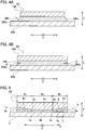
- Fig. 4A and Fig. 4B are diagrams describing the mechanism of how a crack is generated in an adhesive layer 300 in a joined structure Bc according to a comparative example.
- a thickness of the adhesive layer 300 is constant in the X direction.
- Fig. 4A illustrates a shape of a cross section when the joined structure Bc is heated and the adhesive layer 300 is cured (early stage after starting the cooling where the curing is completed).
- Fig. 4B illustrates a shape of a cross section after the joined structure Bc is cooled down to the normal temperature from the state in Fig. 4A .
- the adhesive layer 300 is cured while being deformed in a trapezoid having an X direction length on the side of the member 200 longer than an X direction length on the side of the member 100. Thereafter, once the joined structure Bc is cooled down to the normal temperature, due to a difference of amounts of thermal contraction between the member 100 and the member 200, the joined structure Bc is deformed into a rectangular having the X direction length on the side of the member 200 and the X direction length on the side of the member 100 substantially equal to each other. This deformation generates a shear strain in the adhesive layer 300.
- the shear strain is likely to be increased in end portions 300a on outer sides in the X direction of the adhesive layer 300, and when the shear strain exceeds the shear rupture strain of the adhesive Ad, a crack C may be generated in the adhesive layer 300 as illustrated in Fig. 4B .
- the adhesive layer 3 includes a center region R 1 and a pair of outer edge regions R 2 as illustrated in Fig. 5 .
- the center region R 1 includes the center portion 3b.
- the pair of outer edge regions R 2 extend outward in the X direction from boundary portions 3c on two outer sides in the X direction of the center region R 1 and include the end portions 3a, respectively.
- a thickness in the center region R 1 of the adhesive layer 3 is constant in the X direction.
- a thickness in each outer edge region R 2 is the smallest in the boundary portion 3c between the center region R 1 and the outer edge region R 2 , is increased toward the outer side in the X direction from the boundary portion 3c, and is the greatest in the end portion 3a. That is, the Z direction dimension of the clearance between the attaching surface 4 and the attaching surface 5 is constant within an area in which the attaching surfaces 4 and 5 are put in contact with the center region R 1 .
- the Z direction dimension of the clearance is the smallest in the position in which the attaching surfaces 4 and 5 are put in contact with the boundary portion 3c, is increased toward the outer sides in the X direction from the position of the boundary portion 3c, and is the greatest in the position in which the attaching surfaces 4 and 5 are put in contact with the end portions 3a.
- the attaching surface 5 may be formed of the single flat surface 5a as illustrated in Fig. 5 .
- the attaching surface 4 may be formed of one flat surface 4c parallel to the attaching surface 5 and two flat inclined surfaces 4d.
- each inclined surface 4d is arranged to be inclined with respect to the attaching surface 5, with the inclined surface 4d being farther from the attaching surface 5 as being closer to the outer side in the X direction.
- the flat surface 4c is put in contact with the center region R 1 of the adhesive layer 3, and the two inclined surfaces 4d are respectively put in contact with the outer edge regions R 2 .
- An intersection line 4e of each inclined surface 4d and the flat surface 4c is put in contact with the boundary portion 3c of the adhesive layer 3.
- the thickness of the adhesive layer 3 in the center region R 1 is constant in the X direction, it is possible to secure an optimum thickness of the adhesive layer 3 in a wider area of the center region R 1 and to improve the adherability.
- a lower limit value of the thickness of the adhesive layer 3 in the outer edge regions R 2 is preferably within the range expressed by the above-described expression (1). Consequently, it is possible to obtain the operations and effects similar to the operations and effects described in the above-described [4].
- the adhesive layer 3 includes the center region R 1 , a pair of middle regions R 3 , and the pair of outer edge regions R 2 as illustrated in Fig. 6 .
- the center region R 1 includes the center portion 3b.
- the pair of middle regions R 3 extend outward in the X direction from the boundary portions 3c on the two outer sides in the X direction of the center region R 1 , respectively.
- the pair of outer edge regions R 2 extend outward in the X direction from the boundary portions 3d on the two outer sides in the X direction of the pair of middle regions R 3 and include the end portions 3a, respectively.
- a thickness in each of the center region R 1 and the pair of outer edge regions R 2 of the adhesive layer 3 is constant in the X direction.
- a thickness in each middle region R 3 is the smallest in the boundary portion 3c between the center region R 1 and the middle regions R 3 , is increased toward the outer side in the X direction from the boundary portion 3c, and is the greatest in the boundary portion 3d between the middle regions R 3 and the outer edge regions R 2 . That is, the Z direction dimension of the clearance between the attaching surface 4 and the attaching surface 5 is constant within the area in which the attaching surfaces 4 and 5 are put in contact with each of the center region R 1 and the pair of outer edge regions R 2 .
- the Z direction dimension of the clearance is the smallest in the position in which the attaching surfaces 4 and 5 are put in contact with the boundary portion 3c, is increased toward the outer sides in the X direction from the position of the boundary portion 3c, and is the greatest in the position in which the attaching surfaces 4 and 5 are put in contact with the boundary portions 3d.
- the attaching surface 5 may be formed of the single flat surface 5a as illustrated in Fig. 6 .
- the attaching surface 4 may be formed of three flat inclined surfaces 4c and 4g parallel to the attaching surface 5 and two flat inclined surfaces 4f.
- each inclined surface 4f is arranged to be inclined with respect to the attaching surface 5, with the inclined surface 4f being farther from the attaching surface 5 as being closer to the outer side in the X direction.
- the three flat surfaces 4c and 4g are put in contact with the center region R 1 and the pair of outer edge regions R 2 of the adhesive layer 3, respectively, and the two inclined surfaces 4f are put in contact with the middle regions R 3 of the adhesive layer 3, respectively.
- An intersection line 4h of the flat surface 4c put in contact with the center region R 1 and each inclined surface 4f is put in contact with the boundary portion 3c of the adhesive layer 3.
- An intersection line 4i of the flat surface 4g put in contact with the outer edge region R 2 and each inclined surface 4f is put in contact with the boundary portion 3d of the adhesive layer 3.
- the joined structure B3 of this embodiment since the thickness of the adhesive layer 3 from the boundary portion 3c to the boundary portion 3d is increased toward the outer sides in the X direction, it is possible to distribute the shear strain in the middle regions R 3 more evenly. Additionally, in this embodiment, the attaching surfaces 4 and 5 (flat surfaces 4g and 5a) put in contact with the outer edge regions R 2 of the adhesive layer 3 are parallel to each other. Consequently, management of a clearance between the members 1 and 2 in an assembling step (management of the thickness of the adhesive layer 3) is facilitated, and the accuracy of the dimension, the reliability of the adherability, and the like of the joined structure B3 are improved.
- Lower limit values of the thicknesses of the adhesive layer 3 in the middle regions R 3 and the outer edge regions R 2 are preferably within the range expressed by the above-described expression (1). Consequently, it is possible to obtain the operations and effects similar to the operations and effects described in the above-described [4].
- the second and third embodiments have configurations similar to the configuration of the first embodiment in addition to the above-described configurations, it is possible to obtain the operations and effects similar to the operations and effects described in the above-described [1], [3], and [5]. Additionally, since the method of manufacturing the joined structures B2 and B3 on which the electrodeposition coating has been performed and the operations and effects thereof are similar to the method of manufacturing the joined structure B1 on which the electrodeposition coating has been performed and the operations and effects [6] and [7] thereof, descriptions are omitted.
- the thicknesses of the end portions 3a illustrated in Figs. 1 , 5 , and 6 are equal to each other on the two sides in the X direction in the first to third embodiments, the thicknesses of the end portions 3a may be different from each other on the two sides in the X direction.
- the joined structures B1 to B3 illustrated in Figs. 1 , 5 , and 6 each have a cross section shaped substantially line-symmetric about an axis or a (not illustrated) straight line perpendicular to the plane direction XY passing through the center portion 3b
- the joined structures B1 to B3 may each have the illustrated configuration on only one side of the axis (on only either right side or left side in the diagram). In this case, it is possible to obtain the operations and effects of each of the above-described embodiments on the side having the illustrated configuration. Note that, on the opposite side of the side having the illustrated configuration, the thickness of the adhesive layer 3 may be constant in the X direction.
- the center portion 3b of the adhesive layer 3 is set to the position in which the length in the X direction of the adhesive layer 3 is divided in half in the first to third embodiments, the position of the center portion 3b is not limited thereto.
- the center portion 3b may be displaced in the plane direction XY from the position of dividing in half.
- the center portion 3b may be set in a point in which the shear strain (shear stress affecting the attaching surfaces 4 and 5) due to the difference of amounts of thermal expansion or amounts of thermal contraction between the members 1 and 2 becomes substantially zero.
- the thickness of the adhesive layer 3 is varied (distribution of the thickness is made) in the X direction (longitudinal direction) in the first to third embodiments, the thickness may be varied in a direction other than the X direction such as the Y direction, for example. Additionally, the thickness may be varied in a radial direction toward an outer peripheral end from a center portion in the plane direction of the adhesive layer 3. For example, in a modification of the first embodiment, the thickness of the adhesive layer 3 may be set to be the smallest in the center portion in the plane direction, be increased toward the outer peripheral end from the center portion in the plane direction, and be the greatest in the outer peripheral end.
- the adhesive layer 3 may be sectioned into an outer peripheral region and a plane direction-center region, and a thickness of the adhesive layer 3 in the plane direction-center region may be set to be constant within the region, and a thickness of the adhesive layer 3 in the outer peripheral region may be set to be increased toward the outer peripheral end.
- the adhesive layer 3 may be sectioned into the outer peripheral region, the plane direction-center region, and a circular middle region arranged therebetween, and a thickness of the adhesive layer 3 in the circular middle region may be set to be increased toward the outer peripheral end.
- this specific position In the above-described specific position, the shear strain due to the difference of amounts of thermal expansion or amounts of thermal contraction between the members 1 and 2 becomes substantially zero.
- this specific position is referred to as a reference point P in the plane direction XY.
- the reference point P when relative positions of two intersection points Pa in the plane direction XY, in which interfaces of the adhesive layer 3 with the members 1 and 2 and a straight line L perpendicular to the plane direction XY intersect with each other, are not changed before and after the thermal expansion or the thermal contraction of the members 1 and 2, the position in the plane direction of the intersection points Pa is the reference point P.
- the thickness of the adhesive layer 3 in the end portion 3a farthest from the reference point P in the plane direction XY is greater than the thickness of the adhesive layer 3 in the reference point P. Specifically, in a region on the outer side of the reference point P in the XY direction, the thickness of the adhesive layer 3 is the smallest in the reference point P, is increased toward the outer side in the XY direction from the reference point P, and is the greatest in the end portion 3a.
- the Z direction dimension of the clearance between the attaching surface 4 and the attaching surface 5 is the smallest in a position in which the attaching surface 4 and the attaching surface 5 are put in contact with the reference point P, is increased toward the outer side in the XY direction from the reference point P, and is the greatest in the position in which the attaching surface 4 and the attaching surface 5 are put in contact with the end portion 3a.
- the attaching surface 5 may be formed of the single flat surface 5a, and the attaching surface 4 may be formed of a single flat inclined surface 4j, as illustrated in Fig. 7 .
- the inclined surface 4j is arranged to be inclined with respect to the attaching surface 5, with the inclined surface 4j being farther from the attaching surface 5 as being closer to the outer side in the X direction.
- the thickness in the end portion 3a is greater than the thickness in the reference point P of the adhesive layer 3. Consequently, it is possible to improve the adherability of the the joined structure B4 with the small thickness of the adhesive layer 3 around the reference point P while suppressing the generation of a crack in the adhesive layer 3 by reducing the shear strain in the end portion 3a.
- the thickness of the adhesive layer 3 is increased toward the outer side in the XY direction from the reference point P, it is possible to distribute the shear strain in regions on the outer side of the reference point P in the XY direction more evenly in the plane direction XY. Specifically, in this embodiment, since the thickness of the adhesive layer 3 is increased at a constant incline (linearly in a cross section) toward the outer side in the XY direction from the reference point P, the shear strain distribution becomes more even.
- the shear strain of the adhesive layer 3 is likely to be the greatest in the end portion 3a farthest from the reference point P in the plane direction XY. According to the joined structure B4, since the thickness in the end portion 3a farthest from the reference point P in the plane direction XY is greater than the thickness in the reference point P, it is possible to reduce the maximum value of the shear strain more reliably and to suppress the generation of a crack in the adhesive layer 3 more reliably.
- the lower limit value of the thickness of the adhesive layer 3 in the region on the outer side of the reference point P in the XY direction is preferably set to a value satisfying the expression (1) where a distance from the reference point P in the XY direction is substituted as a variable x. Consequently, it is possible to obtain the operations and effects similar to the operations and effects described in the above-described [4].
- the joined structure B4 can exert the excellent adherability and the effect of preventing a crack in the adhesive layer 3 against a change in temperature in the surrounding environment, it is possible to obtain the operations and effects similar to the operations and effects described in the above-described [5].
- the method of manufacturing the joined structure B4 on which the electrodeposition coating has been performed includes the adhesive applying step S1, the temporary fixing step S2, the electrodeposition coating step S3, and the joining step S4.
- the member 1 and the member 2 are positioned and temporarily fixed such that the Z direction dimension of the clearance between the attaching surface 4 and the attaching surface 5 is the smallest in the position in which the attaching surfaces 4 and 5 are put in contact with the reference point P and is the greatest in the position in which the attaching surfaces 4 and 5 are put in contact with the end portion 3a.
- the thickness of the adhesive layer 3 cured by the heating is the smallest in the reference point P, is increased toward the outer side in the XY direction from the reference point P, and is the greatest in the end portion 3a. Note that, since the other steps are similar to that of the above-described joined structures B1 to B3, descriptions are omitted.
- the thickness of the adhesive layer 3 cured by the heating is set to be greater in the end portion 3a than in the reference point P. Consequently, it is possible to improve the adherability with the small thickness of the adhesive layer 3 around the reference point P while suppressing the generation of a crack in the adhesive layer 3 by reducing the shear strain in the end portion 3a generated in the cooling step after the curing. Additionally, according to this method, since the heat curing type-adhesive Ad is used, the baking of the coating film and the curing of the adhesive Ad can be simultaneously performed by curing once, and consequently, it is possible to manufacture the joined structure B4 on which the electrodeposition coating has been performed with good productivity.
- a center pillar 8 according to the fifth embodiment extends in a vehicle vertical direction in a vehicle front and rear direction-center portion of a body side panel as illustrated in Fig. 8A .
- the center pillar 8 has a closed hollow cross section-configuration and includes a pillar inner 9 and a pillar outer 10 joined to the pillar inner 9 as illustrated in Fig. 8B .
- the pillar outer 10 extends in the vehicle vertical direction on an outer side of the pillar inner 9 in a vehicle width direction and constitutes a vehicle width direction-outer portion of the center pillar 8.
- the pillar outer 10 is the joined structure B5 of this embodiment and includes an inner panel 11 made of carbon fiber reinforced plastic, an outer panel 12 made of a steel plate, and the adhesive layer 3 arranged between the inner panel 11 and the outer panel 12 to join the inner and outer panels 11 and 12 together.
- the outer panel 12 has a hat-shaped cross section as illustrated in Fig. 8B .
- the outer panel 12 includes a vertical wall portion 12a, a front wall portion 12b and a rear wall portion 12c respectively extending inward in the vehicle width direction from a front end and a rear end of the vertical wall portion 12a, and a front flange 12d and a rear flange 12e respectively extending frontward and rearward from inner ends of the front wall portion 12b and the rear wall portion 12c.
- the inner panel 11 extends along the front wall portion 12b, the vertical wall portion 12a, and the rear wall portion 12c of the outer panel 12 and is attached on surfaces on inner sides of closed cross sections of the front, vertical, and rear wall portions 12b, 12a, and 12c with the adhesive Ad.
- the inner panel 11 extends in the vehicle vertical direction over an area of about 3/4 of the total length of the center pillar 8.
- the pillar outer 10 has a configuration similar to the configuration illustrated in Fig. 5 in a cross section along a longitudinal direction of the pillar outer 10 or the X direction of the adhesive layer 3 (S 2 -S 2 cross section in Fig. 8B ).
- the member 1 in Fig. 5 corresponds to the inner panel 11
- the member 2 in Fig. 5 corresponds to the outer panel 12
- the X direction in Fig. 5 corresponds to the extending direction of the pillar outer 10, respectively. Since specific configurations of an attaching surface of the inner panel 11, an attaching surface of the outer panel 12, and the adhesive layer 3 are similar to that of the attaching surface 4, the attaching surface 5, and the adhesive layer 3 according to the second embodiment, descriptions are omitted.
- the adhesive layer 3 includes the center region R 1 and the pair of outer edge regions R 2 as illustrated in Fig. 8B .
- the center region R 1 is put in contact with the vertical wall portion 12a of the outer panel 12, and the pair of outer edge regions R 2 are put in contact with the front wall portion 12b and the rear wall portion 12c, respectively.
- the center region R 1 includes the center portion 3b, and the pair of outer edge regions R 2 extend outward in the Y direction from the boundary portions 3c on two outer sides in the Y direction of the center region R 1 and include the end portions 3a, respectively.
- a thickness in the center region R 1 of the adhesive layer 3 is constant in the Y direction.
- a thickness of the adhesive layer 3 in each outer edge region R 2 is the smallest in the boundary portion 3c between the center region R 1 and the outer edge region R 2 , is increased toward the outer side in the Y direction from the boundary portion 3c, and is the greatest in the pair of end portions 3a.
- the pillar outer 10 as the joined structure B5 of this embodiment since the configurations of the adhesive layer 3 in both the X direction and the Y direction are similar to that of the second embodiment, it is possible to obtain the operations and effects similar to at least that of the second embodiment.
- the configuration of the first, third, or fourth embodiment to the configuration of joining the inner panel 11 and the outer panel 12 together.
- the configuration of the cross section along the longitudinal direction of the pillar outer 10 (S 2 -S 2 cross section in Fig. 8B ) is similar to the configuration illustrated in Fig. 1 , 6, or 7 .
- a hood 13 according to the sixth embodiment constitutes a top surface of a vehicle body front portion and covers the top of an engine room.
- the hood 13 includes a hood outer panel 15 made of a steel plate, a hood inner panel 14 made of carbon fiber reinforced plastic, and the adhesive layer 3 arranged between the hood outer panel 15 and the hood inner panel 14 to join the hood outer and inner panels 15 and 14 together, as illustrated in Fig. 9 .
- the hood inner panel 14 is attached to a bottom surface of the hood outer panel 15 with the adhesive Ad.
- the hood 13 is the joined structure B6 of this embodiment and has a configuration similar to the configuration illustrated in Fig. 5 in a cross section along the vehicle front and rear direction (S 3 -S 3 cross section) and a cross section along the vehicle width direction (S 4 -S 4 cross section).
- the member 1 in Fig. 5 corresponds to the hood inner panel 14, the member 2 in Fig. 5 corresponds to the hood outer panel 15, the X direction in Fig. 5 corresponds to either one of the vehicle front and rear direction and the vehicle width direction, and the Y direction in Fig. 5 corresponds to the other one of the vehicle front and rear direction and the vehicle width direction, respectively.
- the hood 13 as the joined structure B6 of this embodiment since the configurations of the adhesive layer 3 in both the X direction and the Y direction are similar to that of the second embodiment, it is possible to obtain the operations and effects similar to at least that of the second embodiment.
- the configuration of the first, third, or fourth embodiment is also possible to apply the configuration of the first, third, or fourth embodiment to the configuration of joining the hood inner panel 14 and the hood outer panel 15.
- the configuration of the hood 13 in the cross section along the vehicle front and rear direction (S 3 -S 3 cross section) and the cross section along the vehicle width direction (S 4 -S 4 cross section) is similar to the configuration illustrated in Fig. 1 , 6, or 7 .
- the inclined surfaces 4a, 4d, 4f, and 4j are formed on only the side of the attaching surface 4 in the above-described embodiments and the like, the inclined surfaces 4a, 4d, 4f, and 4j may be provided on only the side of the attaching surface 5, or may be provided on both the attaching surfaces 4 and 5.
- the attaching surfaces 4 and 5 are formed of a combination of the flat surfaces (flat surfaces 4c and 4g and inclined surfaces 4a, 4d, 4f, and 4j)
- the attaching surfaces 4 and 5 may be formed of bent surfaces, curved surfaces, a combination of those surfaces and the flat surfaces, or the like.
- partial configurations of the attaching surfaces 4 and 5 of the first to fourth embodiments may be combined in the plane direction.
- the adhesive Ad is arranged continuously in the plane direction XY with no clearance in the adhesive layer 3 of the above-described embodiments, the adhesive Ad may be arranged discontinuously in the plane direction XY so as to be in the form of borders (such as form of belts or form of lines), the form of spots, or the like viewed in the Z direction of the adhesive layer 3. Additionally, the adhesive layer 3 in a partial region such as, for example, the center portion 3b, around the center portion 3b, the center region R 1 , and the middle region R 3 may be omitted without falling below the required adherability. Consequently, it is possible to save the amount of using the adhesive Ad.
- the joined structures B1 to B6 may include a third member joined to either of the members 1 and 2 with the adhesive layer 3 arranged therebetween.
- the third member may be formed of a material having coefficients of linear expansion different from either of that of the members 1 and 2.
- an attaching surface substantially parallel to the adhesive layer 3 may be provided to either of the members 1 and 2
- an adhesive layer similar to the adhesive layer 3 of the above-described embodiments and the like may be provided between the attaching surface and an attaching surface of the third member. Consequently, it is possible to obtain the operations and effects similar to that of the above-described embodiments also in the joint portion of the third member.
- the joined structure according to the present invention can be utilized as a constituent member of a vehicle such as an automobile that is, for example, a hood, a floor panel, a door panel, a bumper, a trunk lid, a rear gate, a fender panel, a side body panel, a roof panel, and so on. Additionally, the joined structure according to the present invention can be utilized as a constituent member of a transport vehicle such as an air plane, a ship, and a train vehicle, a household electronic, a power generation facility, a production machinery, housing equipment, furniture, a leisure product, and the like.
- a transport vehicle such as an air plane, a ship, and a train vehicle, a household electronic, a power generation facility, a production machinery, housing equipment, furniture, a leisure product, and the like.
Landscapes
- Engineering & Computer Science (AREA)
- Mechanical Engineering (AREA)
- Chemical & Material Sciences (AREA)
- Chemical Kinetics & Catalysis (AREA)
- General Chemical & Material Sciences (AREA)
- Standing Axle, Rod, Or Tube Structures Coupled By Welding, Adhesion, Or Deposition (AREA)
- Body Structure For Vehicles (AREA)
- Laminated Bodies (AREA)
- Adhesives Or Adhesive Processes (AREA)
Abstract
Description
- The present invention relates to a joined structure in which two members which are made of materials having coefficients of linear expansion different from each other (hereinafter, also referred to as "different material members") are joined together with an adhesive layer arranged therebetween, and a method of manufacturing the joined structure.
- Japanese Patent Application Publication No.
2017-185911 - Incidentally, in a joined structure in which different material members are joined together with an adhesive layer arranged therebetween, when the temperature of the surrounding environment is changed for example, a difference between amounts of thermal expansion or amounts of thermal contraction of the different material members causes a strain in the adhesive layer. In terms of securing the adherability demanded of the joined structure, the adhesive layer is required to be formed thin; however, there is a problem that the thinner the adhesive layer is formed, the more the above-described strain is increased and the more likely a crack is to be generated.
- An object of the present invention is to improve the adherability of a joined structure in which different material members are joined together with an adhesive layer arranged therebetween, while suppressing generation of a crack in the adhesive layer.
- An aspect of the present invention is a joined structure in which an adhesive layer includes at least an end portion in one direction parallel to a plane direction of the adhesive layer and a center portion in the one direction, and a thickness in the end portion is greater than a thickness in the center portion.
- According to the above-described joined structure, it is possible to improve the adherability while suppressing generation of a crack in the adhesive layer.
-
- [
Fig. 1] Fig. 1 is a cross-sectional view of a joined structure according to a first embodiment. - [
Fig. 2] Fig. 2 is a graph indicating a favorable range of a lower limit value of a thickness of an adhesive layer. - [
Fig. 3] Fig. 3 is a flowchart indicating a method of manufacturing the joined structure. - [
Fig. 4A] Fig. 4A is a diagram describing a mechanism of generation of a crack in an adhesive layer according to a comparative example. - [
Fig. 4B] Fig. 4B is a diagram followingFig. 4A . - [
Fig. 5] Fig. 5 is a cross-sectional view of a joined structure according to a second embodiment. - [
Fig. 6] Fig. 6 is a cross-sectional view of a joined structure according to a third embodiment. - [
Fig. 7] Fig. 7 is a cross-sectional view of a joined structure according to a fourth embodiment. - [
Fig. 8A] Fig. 8A is a perspective view of a center pillar according to a fifth embodiment. - [
Fig. 8B] Fig. 8B is a cross-sectional view taken along S1-S1 inFig. 8A . - [
Fig. 9] Fig. 9 is a perspective view of a hood according to a sixth embodiment seen from below. - Hereinafter, joined structures according to some embodiments are described with reference to the drawings.
- As illustrated in
Fig. 1 , a joined structure B1 according to a first embodiment includes a first member 1 (hereinafter, member 1), a second member 2 (hereinafter, member 2), and anadhesive layer 3 arranged between themember 1 and themember 2 to join themembers member 1 and themember 2 are formed of materials having coefficients of linear expansion different from each other. - The
member 1 is a member in the form of a plate made of carbon fiber reinforced plastic. The carbon fibers as reinforcement fibers are made of continuous fibers and, for example, may have a lamination configuration in which the reinforcement fibers facing in one direction are laminated at different angles, or the form of a cloth. Fibers such as polyacrylonitrile (PAN-based), pitch-based, cellulose-based, vapor deposition-based carbon fibers using carbon hydride, or graphite fibers may be used as the carbon fibers, for example. Two or more types of these fibers may be combined with each other for use. The carbon fibers may include short fibers. A publicly known thermoset resin or thermoplastic resin may be used as a matrix resin. Specifically, for example, a resin such as an epoxy resin, a phenol resin, an unsaturated polyester resin, a vinyl ester resin, a polyimide resin, a polycarbonate resin, a polyamide resin, or a polyphenylene sulfide (PPS) resin may be used. - The
member 2 is a member in the form of a plate made of a steel plate. Note that, the materials of themembers - The shape of each of the
members - The
member 1 includes a first attaching surface 4 (hereinafter, attaching surface 4). Themember 2 includes a second attaching surface 5 (hereinafter, attaching surface 5). The attachingsurface 5 is arranged to face the attachingsurface 4 with theadhesive layer 3 arranged therebetween. The attachingsurface 4 is a region of a surface of themember 1 that is directly put in contact with theadhesive layer 3, while the attachingsurface 5 is a region of a surface of themember 2 that is directly put in contact with theadhesive layer 3. - The
adhesive layer 3 is a layer formed of an adhesive Ad. The adhesive Ad is not particularly limited, and a publicly known adhesive such as an acryl-based, an epoxy-based, a urethane-based, a silicone-based, or a modified silicone-based may be used, for example. The adhesive Ad may be either of a normal temperature curing type and a heat curing type and may be either of a single component type and a two component type. - The
adhesive layer 3 includes a plane direction XY (hereinafter, also referred to as XY direction) in a direction substantially parallel to the attachingsurface 4 and the attachingsurface 5 that is, specifically, a direction along a virtual plane V that is equidistant from the two attachingsurfaces adhesive layer 3 is a direction orthogonal to the virtual plane V. Theadhesive layer 3 includes a longitudinal direction X (hereinafter, X direction) in one direction parallel to the plane direction XY. The one direction parallel to the plane direction XY is a direction parallel to an axis of coordinate of orthogonal coordinates on the virtual plane V. Theadhesive layer 3 includes a transverse direction Y (hereinafter, Y direction) in a direction orthogonal to the X direction. - In the
adhesive layer 3, a surface on one side in the Z direction (upper side inFig. 1 ) is put in contact with the attachingsurface 4, and a surface on the other side in the Z direction (lower side inFig. 1 ) is put in contact with the attachingsurface 5. Additionally, theadhesive layer 3 includes a pair ofend portions 3a positioned on two outer sides in the X direction and acenter portion 3b positioned between theend portions 3a. In this embodiment, thecenter portion 3b is positioned in a position in which a length in the X direction of theadhesive layer 3 is divided in half. - A thickness of the
adhesive layer 3 is the smallest in thecenter portion 3b, is increased toward the outer sides in the X direction from thecenter portion 3b, and is the greatest in the pair of theend portions 3a. That is, a Z direction dimension of a clearance between the attachingsurface 4 and the attachingsurface 5 is the smallest in a position in which the attachingsurface 4 and the attachingsurface 5 are put in contact with thecenter portion 3b, is increased toward the outer sides in the X direction from the position of thecenter portion 3b, and is the greatest in a position in which the attachingsurface 4 and the attachingsurface 5 are put in contact with theend portions 3a. - The attaching
surface 5 may be formed of a singleflat surface 5a as illustrated inFig. 1 . The attachingsurface 4 may be formed of two flatinclined surfaces 4a. In this case, eachinclined surface 4a is arranged to be inclined with respect to the attachingsurface 5, with theinclined surface 4a being farther from the attachingsurface 5 as being closer to the outer side in the X direction. Anintersection line 4b of the twoinclined surfaces 4a is put in contact with thecenter portion 3b of theadhesive layer 3. The shape of each of the attachingsurfaces - Hereinafter, operations and effects of this embodiment are described.
- [1] In the joined structure in which the different material members are joined together with the adhesive layer arranged therebetween, when the temperature of the joined structure is changed because of a change in the temperature of the surrounding environment, for example, a shear strain due to a difference of the coefficients of linear expansion between the different material members is generated in the adhesive layer. When the thickness of the adhesive layer is constant in the plane direction, the shear strain is likely to be great in the end portions on the outer sides in the plane direction of the adhesive layer, and if the shear strain exceeds a rupture strain of the adhesive, a crack may be generated in the adhesive layer. On the other hand, if the thickness of the adhesive layer is uniformly increased to reduce the shear strain in order to avoid the crack, the adherability of the joined structure may be degraded.
According to the joined structure B1 of this embodiment, the thickness in theend portions 3a of theadhesive layer 3 is greater than the thickness in thecenter portion 3b thereof. Consequently, it is possible to improve the adherability with the small thickness in thecenter portion 3b while suppressing generation of a crack in theadhesive layer 3 by reducing the shear strain in theend portions 3a. - [2] Additionally, the shear strain in the
adhesive layer 3 has a tendency to be distributed so as to be increased toward the outer sides in the X direction from thecenter portion 3b. According to the joined structure B1, since the thickness of theadhesive layer 3 is increased toward the outer sides in the X direction from thecenter portion 3b like the distribution tendency of the shear strain, it is possible to distribute the shear strain of theadhesive layer 3 more evenly in the X direction. Consequently, it is possible to alleviate a local concentration of the shear strain and to suppress the generation of a crack in theadhesive layer 3 more reliably. Specifically, in this embodiment, since the thickness of theadhesive layer 3 is increased at a constant incline (linearly in a cross section) toward the outer sides in the X direction from thecenter portion 3b, the shear strain is distributed more evenly. - [3] Moreover, the shear strain of the
adhesive layer 3 has a tendency to be the greatest in theend portions 3a in the X direction (longitudinal direction) among end portions on outer sides in the XY direction. According to the joined structure B1, since the thickness of theend portions 3a positioned on the two outer sides in the X direction is greater than the thickness of thecenter portion 3b, it is possible to reduce the maximum value of the shear strain more reliably and to suppress the generation of a crack in theadhesive layer 3 more reliably. - [4] It is favorable to set a lower limit value of the thickness of the
adhesive layer 3 to be within a range expressed by the following expression (1) (shaded area inFig. 2 ). Consequently, the shear strain generated in the adhesive Ad of theadhesive layer 3 can be kept less than a shear rupture strain τB, and this makes it possible to reduce the generation of a crack in theadhesive layer 3 more reliably:
[Math. 1]
- where x: a position in the X direction with the
center portion 3b set as an origin, t: a thickness of theadhesive layer 3, α1: a coefficient of linear expansion of the material of themember 1, α2: a coefficient of linear expansion of the material of themember 2, ΔT: an amount of change in temperature of the joined structure B1 (members 1 and 2), and εB: a tensile rupture strain of the adhesive Ad, and - εB and the shear rupture strain τB of the adhesive Ad satisfy τB = 2·εB.
- where x: a position in the X direction with the
- [5] Additionally, since the joined structure B1 can exert the excellent adherability and the effect of preventing a crack in the
adhesive layer 3 against a change in temperature in the surrounding environment, the joined structure B1 is favorable as a member used in a step involving a relatively great change in temperature such as a baking step of electrodeposition coating. According to the joined structure B1 on which the electrodeposition coating has been performed, it is possible to obtain a product in which the generation of a crack due to a thermal expansion or a thermal contraction in the baking step is suppressed and the corrosion resistance and the strength reliability are improved. - Hereinafter, a method of manufacturing the joined structure B1 on which the electrodeposition coating has been performed is described with reference to
Fig. 3 . This method includes an adhesive applying step S1, a temporary fixing step S2, an electrodeposition coating step S3, and a joining step S4. This method may include a step such as an intermediate coating step and an over coating step after the joining step S4 and may include a step such as a step of degreasing and cleaning the attachingsurfaces - In the adhesive applying step S1, the adhesive Ad is applied to either one of or both the attaching
surfaces - In the temporary fixing step S2, the
member 1 and themember 2 to which the adhesive is already applied are put together with the uncuredadhesive layer 3 arranged therebetween, and is temporarily fixed by a temporary fixing jig. The temporary fixing is performed with themember 1 and themember 2 positioned such that the Z direction dimension of the clearance between the attachingsurface 4 and the attachingsurface 5 is the smallest in the position in which both the attachingsurfaces center portion 3b and is the greatest in the position in which both the attachingsurfaces end portions 3a. - In the electrodeposition coating step S3, the electrodeposition coating is performed on the temporarily fixed
members members members members - In the joining step S4, the
member 1 and themember 2 are joined together by curing theadhesive layer 3 while heating themembers members adhesive layer 3 is greater in theend portions 3a on the two outer sides in the X direction than in thecenter portion 3b in the X direction of theadhesive layer 3. After the joining step S4, the joined structure B1 is cooled down to the normal temperature. - Hereinafter, the operations and effects of this method are described.
-
Fig. 4A and Fig. 4B are diagrams describing the mechanism of how a crack is generated in anadhesive layer 300 in a joined structure Bc according to a comparative example. In the joined structure Be, a thickness of theadhesive layer 300 is constant in the X direction.Fig. 4A illustrates a shape of a cross section when the joined structure Bc is heated and theadhesive layer 300 is cured (early stage after starting the cooling where the curing is completed).Fig. 4B illustrates a shape of a cross section after the joined structure Bc is cooled down to the normal temperature from the state inFig. 4A . - Due to a difference of amounts of thermal expansion between a
member 100 and amember 200, theadhesive layer 300 is cured while being deformed in a trapezoid having an X direction length on the side of themember 200 longer than an X direction length on the side of themember 100. Thereafter, once the joined structure Bc is cooled down to the normal temperature, due to a difference of amounts of thermal contraction between themember 100 and themember 200, the joined structure Bc is deformed into a rectangular having the X direction length on the side of themember 200 and the X direction length on the side of themember 100 substantially equal to each other. This deformation generates a shear strain in theadhesive layer 300. The shear strain is likely to be increased inend portions 300a on outer sides in the X direction of theadhesive layer 300, and when the shear strain exceeds the shear rupture strain of the adhesive Ad, a crack C may be generated in theadhesive layer 300 as illustrated inFig. 4B . - [6] According to this method, the thickness of the
adhesive layer 3 cured by the heating is set to be greater in theend portions 3a than in thecenter portion 3b. Consequently, it is possible to improve the adherability with the small thickness in thecenter portion 3b while suppressing the generation of a crack in theadhesive layer 3 by reducing the shear strain in theend portions 3a generated in the cooling step after the curing. - [7] Additionally, according to this method, since the heat curing type-adhesive Ad of which the curing temperature is equal to the baking temperature of the coating film is used, the baking of the coating film and the curing of the adhesive Ad can be simultaneously performed by curing once. Consequently, it is possible to manufacture the joined structure B1 on which the electrodeposition coating has been performed with good productivity.
- Next, joined structures B2 to B6 according to second to sixth embodiments are described with reference to
Figs. 5 to 9 . Note that, configurations of the following embodiments different from that of each of the preceding embodiments are only described, and a description of a configuration similar to the configuration already described is omitted while using a similar reference sign. - In the second embodiment, the
adhesive layer 3 includes a center region R1 and a pair of outer edge regions R2 as illustrated inFig. 5 . The center region R1 includes thecenter portion 3b. The pair of outer edge regions R2 extend outward in the X direction fromboundary portions 3c on two outer sides in the X direction of the center region R1 and include theend portions 3a, respectively. - A thickness in the center region R1 of the
adhesive layer 3 is constant in the X direction. A thickness in each outer edge region R2 is the smallest in theboundary portion 3c between the center region R1 and the outer edge region R2, is increased toward the outer side in the X direction from theboundary portion 3c, and is the greatest in theend portion 3a. That is, the Z direction dimension of the clearance between the attachingsurface 4 and the attachingsurface 5 is constant within an area in which the attachingsurfaces surfaces boundary portion 3c, is increased toward the outer sides in the X direction from the position of theboundary portion 3c, and is the greatest in the position in which the attachingsurfaces end portions 3a. - The attaching
surface 5 may be formed of the singleflat surface 5a as illustrated inFig. 5 . The attachingsurface 4 may be formed of oneflat surface 4c parallel to the attachingsurface 5 and two flatinclined surfaces 4d. In this case, eachinclined surface 4d is arranged to be inclined with respect to the attachingsurface 5, with theinclined surface 4d being farther from the attachingsurface 5 as being closer to the outer side in the X direction. Theflat surface 4c is put in contact with the center region R1 of theadhesive layer 3, and the twoinclined surfaces 4d are respectively put in contact with the outer edge regions R2.An intersection line 4e of eachinclined surface 4d and theflat surface 4c is put in contact with theboundary portion 3c of theadhesive layer 3. - According to the joined structure B2 of this embodiment, since the thickness of the
adhesive layer 3 in the center region R1 is constant in the X direction, it is possible to secure an optimum thickness of theadhesive layer 3 in a wider area of the center region R1 and to improve the adherability. - Additionally, according to this embodiment, since the thickness of the
adhesive layer 3 is increased toward the outer sides in the X direction from theboundary portion 3c, it is possible to distribute the shear strain in the outer edge regions R2 more evenly in the X direction. Note that, a lower limit value of the thickness of theadhesive layer 3 in the outer edge regions R2 is preferably within the range expressed by the above-described expression (1). Consequently, it is possible to obtain the operations and effects similar to the operations and effects described in the above-described [4]. - In the third embodiment, the
adhesive layer 3 includes the center region R1, a pair of middle regions R3, and the pair of outer edge regions R2 as illustrated inFig. 6 . The center region R1 includes thecenter portion 3b. The pair of middle regions R3 extend outward in the X direction from theboundary portions 3c on the two outer sides in the X direction of the center region R1, respectively. The pair of outer edge regions R2 extend outward in the X direction from theboundary portions 3d on the two outer sides in the X direction of the pair of middle regions R3 and include theend portions 3a, respectively. - A thickness in each of the center region R1 and the pair of outer edge regions R2 of the
adhesive layer 3 is constant in the X direction. A thickness in each middle region R3 is the smallest in theboundary portion 3c between the center region R1 and the middle regions R3, is increased toward the outer side in the X direction from theboundary portion 3c, and is the greatest in theboundary portion 3d between the middle regions R3 and the outer edge regions R2. That is, the Z direction dimension of the clearance between the attachingsurface 4 and the attachingsurface 5 is constant within the area in which the attachingsurfaces surfaces boundary portion 3c, is increased toward the outer sides in the X direction from the position of theboundary portion 3c, and is the greatest in the position in which the attachingsurfaces boundary portions 3d. - The attaching
surface 5 may be formed of the singleflat surface 5a as illustrated inFig. 6 . The attachingsurface 4 may be formed of three flatinclined surfaces surface 5 and two flatinclined surfaces 4f. In this case, eachinclined surface 4f is arranged to be inclined with respect to the attachingsurface 5, with theinclined surface 4f being farther from the attachingsurface 5 as being closer to the outer side in the X direction. The threeflat surfaces adhesive layer 3, respectively, and the twoinclined surfaces 4f are put in contact with the middle regions R3 of theadhesive layer 3, respectively. Anintersection line 4h of theflat surface 4c put in contact with the center region R1 and eachinclined surface 4f is put in contact with theboundary portion 3c of theadhesive layer 3. Anintersection line 4i of theflat surface 4g put in contact with the outer edge region R2 and eachinclined surface 4f is put in contact with theboundary portion 3d of theadhesive layer 3. - According to the joined structure B3 of this embodiment, since the thickness of the
adhesive layer 3 from theboundary portion 3c to theboundary portion 3d is increased toward the outer sides in the X direction, it is possible to distribute the shear strain in the middle regions R3 more evenly. Additionally, in this embodiment, the attachingsurfaces 4 and 5 (flat surfaces adhesive layer 3 are parallel to each other. Consequently, management of a clearance between themembers - Lower limit values of the thicknesses of the
adhesive layer 3 in the middle regions R3 and the outer edge regions R2 are preferably within the range expressed by the above-described expression (1). Consequently, it is possible to obtain the operations and effects similar to the operations and effects described in the above-described [4]. - Since the second and third embodiments have configurations similar to the configuration of the first embodiment in addition to the above-described configurations, it is possible to obtain the operations and effects similar to the operations and effects described in the above-described [1], [3], and [5]. Additionally, since the method of manufacturing the joined structures B2 and B3 on which the electrodeposition coating has been performed and the operations and effects thereof are similar to the method of manufacturing the joined structure B1 on which the electrodeposition coating has been performed and the operations and effects [6] and [7] thereof, descriptions are omitted.
- Although the thicknesses of the
end portions 3a illustrated inFigs. 1 ,5 , and6 are equal to each other on the two sides in the X direction in the first to third embodiments, the thicknesses of theend portions 3a may be different from each other on the two sides in the X direction. Additionally, although the joined structures B1 to B3 illustrated inFigs. 1 ,5 , and6 each have a cross section shaped substantially line-symmetric about an axis or a (not illustrated) straight line perpendicular to the plane direction XY passing through thecenter portion 3b, the joined structures B1 to B3 may each have the illustrated configuration on only one side of the axis (on only either right side or left side in the diagram). In this case, it is possible to obtain the operations and effects of each of the above-described embodiments on the side having the illustrated configuration. Note that, on the opposite side of the side having the illustrated configuration, the thickness of theadhesive layer 3 may be constant in the X direction. - Moreover, although the
center portion 3b of theadhesive layer 3 is set to the position in which the length in the X direction of theadhesive layer 3 is divided in half in the first to third embodiments, the position of thecenter portion 3b is not limited thereto. Thecenter portion 3b may be displaced in the plane direction XY from the position of dividing in half. For example, when theadhesive layer 3 extends in an asymmetric shape viewed in the Z direction, thecenter portion 3b may be set in a point in which the shear strain (shear stress affecting the attachingsurfaces 4 and 5) due to the difference of amounts of thermal expansion or amounts of thermal contraction between themembers - Furthermore, although the thickness of the
adhesive layer 3 is varied (distribution of the thickness is made) in the X direction (longitudinal direction) in the first to third embodiments, the thickness may be varied in a direction other than the X direction such as the Y direction, for example. Additionally, the thickness may be varied in a radial direction toward an outer peripheral end from a center portion in the plane direction of theadhesive layer 3. For example, in a modification of the first embodiment, the thickness of theadhesive layer 3 may be set to be the smallest in the center portion in the plane direction, be increased toward the outer peripheral end from the center portion in the plane direction, and be the greatest in the outer peripheral end. Moreover, in a modification of the second embodiment, theadhesive layer 3 may be sectioned into an outer peripheral region and a plane direction-center region, and a thickness of theadhesive layer 3 in the plane direction-center region may be set to be constant within the region, and a thickness of theadhesive layer 3 in the outer peripheral region may be set to be increased toward the outer peripheral end. Likewise, in a modification of the third embodiment, theadhesive layer 3 may be sectioned into the outer peripheral region, the plane direction-center region, and a circular middle region arranged therebetween, and a thickness of theadhesive layer 3 in the circular middle region may be set to be increased toward the outer peripheral end. In each modification, it is possible to obtain the operations and effects similar to the operations and effects of each of the above-described embodiments in the direction in which the thickness distribution is made in theadhesive layer 3. - In the joined structure, in a specific position in the plane direction XY of the
adhesive layer 3, movement of the attachingsurface 5 with respect to the attaching surface 4 (relative displacement) in the plane direction XY may be restricted in some cases. For example, it is the case where aprotrusion portion 7 formed on themember 2 is engaged with aconcave portion 6 formed on themember 1 as illustrated inFig. 7 , the case where themembers surfaces surfaces - In the above-described specific position, the shear strain due to the difference of amounts of thermal expansion or amounts of thermal contraction between the
members adhesive layer 3 with themembers members - In the fourth embodiment, as illustrated in
Fig. 7 , the thickness of theadhesive layer 3 in theend portion 3a farthest from the reference point P in the plane direction XY is greater than the thickness of theadhesive layer 3 in the reference point P. Specifically, in a region on the outer side of the reference point P in the XY direction, the thickness of theadhesive layer 3 is the smallest in the reference point P, is increased toward the outer side in the XY direction from the reference point P, and is the greatest in theend portion 3a. That is, the Z direction dimension of the clearance between the attachingsurface 4 and the attachingsurface 5 is the smallest in a position in which the attachingsurface 4 and the attachingsurface 5 are put in contact with the reference point P, is increased toward the outer side in the XY direction from the reference point P, and is the greatest in the position in which the attachingsurface 4 and the attachingsurface 5 are put in contact with theend portion 3a. - In the region on the outer side of the reference point P in the XY direction, the attaching
surface 5 may be formed of the singleflat surface 5a, and the attachingsurface 4 may be formed of a single flatinclined surface 4j, as illustrated inFig. 7 . In this case, theinclined surface 4j is arranged to be inclined with respect to the attachingsurface 5, with theinclined surface 4j being farther from the attachingsurface 5 as being closer to the outer side in the X direction. - According to the joined structure B4 of this embodiment, the thickness in the
end portion 3a is greater than the thickness in the reference point P of theadhesive layer 3. Consequently, it is possible to improve the adherability of the the joined structure B4 with the small thickness of theadhesive layer 3 around the reference point P while suppressing the generation of a crack in theadhesive layer 3 by reducing the shear strain in theend portion 3a. - Additionally, according to the joined structure B4, since the thickness of the
adhesive layer 3 is increased toward the outer side in the XY direction from the reference point P, it is possible to distribute the shear strain in regions on the outer side of the reference point P in the XY direction more evenly in the plane direction XY. Specifically, in this embodiment, since the thickness of theadhesive layer 3 is increased at a constant incline (linearly in a cross section) toward the outer side in the XY direction from the reference point P, the shear strain distribution becomes more even. - Moreover, the shear strain of the
adhesive layer 3 is likely to be the greatest in theend portion 3a farthest from the reference point P in the plane direction XY. According to the joined structure B4, since the thickness in theend portion 3a farthest from the reference point P in the plane direction XY is greater than the thickness in the reference point P, it is possible to reduce the maximum value of the shear strain more reliably and to suppress the generation of a crack in theadhesive layer 3 more reliably. - Note that, the lower limit value of the thickness of the
adhesive layer 3 in the region on the outer side of the reference point P in the XY direction is preferably set to a value satisfying the expression (1) where a distance from the reference point P in the XY direction is substituted as a variable x. Consequently, it is possible to obtain the operations and effects similar to the operations and effects described in the above-described [4]. - Furthermore, since the joined structure B4 can exert the excellent adherability and the effect of preventing a crack in the
adhesive layer 3 against a change in temperature in the surrounding environment, it is possible to obtain the operations and effects similar to the operations and effects described in the above-described [5]. - Like the above-described method of manufacturing the joined structures B1 to B3, the method of manufacturing the joined structure B4 on which the electrodeposition coating has been performed includes the adhesive applying step S1, the temporary fixing step S2, the electrodeposition coating step S3, and the joining step S4.
- In the temporary fixing step S2, the
member 1 and themember 2 are positioned and temporarily fixed such that the Z direction dimension of the clearance between the attachingsurface 4 and the attachingsurface 5 is the smallest in the position in which the attachingsurfaces surfaces end portion 3a. - In the joining step S4, the thickness of the
adhesive layer 3 cured by the heating is the smallest in the reference point P, is increased toward the outer side in the XY direction from the reference point P, and is the greatest in theend portion 3a. Note that, since the other steps are similar to that of the above-described joined structures B1 to B3, descriptions are omitted. - According to this method, the thickness of the
adhesive layer 3 cured by the heating is set to be greater in theend portion 3a than in the reference point P. Consequently, it is possible to improve the adherability with the small thickness of theadhesive layer 3 around the reference point P while suppressing the generation of a crack in theadhesive layer 3 by reducing the shear strain in theend portion 3a generated in the cooling step after the curing. Additionally, according to this method, since the heat curing type-adhesive Ad is used, the baking of the coating film and the curing of the adhesive Ad can be simultaneously performed by curing once, and consequently, it is possible to manufacture the joined structure B4 on which the electrodeposition coating has been performed with good productivity. - A
center pillar 8 according to the fifth embodiment extends in a vehicle vertical direction in a vehicle front and rear direction-center portion of a body side panel as illustrated inFig. 8A . Thecenter pillar 8 has a closed hollow cross section-configuration and includes a pillar inner 9 and a pillar outer 10 joined to the pillar inner 9 as illustrated inFig. 8B . - The pillar outer 10 extends in the vehicle vertical direction on an outer side of the pillar inner 9 in a vehicle width direction and constitutes a vehicle width direction-outer portion of the
center pillar 8. The pillar outer 10 is the joined structure B5 of this embodiment and includes aninner panel 11 made of carbon fiber reinforced plastic, anouter panel 12 made of a steel plate, and theadhesive layer 3 arranged between theinner panel 11 and theouter panel 12 to join the inner andouter panels - The
outer panel 12 has a hat-shaped cross section as illustrated inFig. 8B . Specifically, theouter panel 12 includes avertical wall portion 12a, afront wall portion 12b and arear wall portion 12c respectively extending inward in the vehicle width direction from a front end and a rear end of thevertical wall portion 12a, and afront flange 12d and arear flange 12e respectively extending frontward and rearward from inner ends of thefront wall portion 12b and therear wall portion 12c. - In a transverse cross section, the
inner panel 11 extends along thefront wall portion 12b, thevertical wall portion 12a, and therear wall portion 12c of theouter panel 12 and is attached on surfaces on inner sides of closed cross sections of the front, vertical, andrear wall portions inner panel 11 extends in the vehicle vertical direction over an area of about 3/4 of the total length of thecenter pillar 8. - The pillar outer 10 has a configuration similar to the configuration illustrated in
Fig. 5 in a cross section along a longitudinal direction of the pillar outer 10 or the X direction of the adhesive layer 3 (S2-S2 cross section inFig. 8B ). Themember 1 inFig. 5 corresponds to theinner panel 11, themember 2 inFig. 5 corresponds to theouter panel 12, and the X direction inFig. 5 corresponds to the extending direction of the pillar outer 10, respectively. Since specific configurations of an attaching surface of theinner panel 11, an attaching surface of theouter panel 12, and theadhesive layer 3 are similar to that of the attachingsurface 4, the attachingsurface 5, and theadhesive layer 3 according to the second embodiment, descriptions are omitted. - In a cross section perpendicular to the longitudinal direction of the pillar outer 10, or a cross section perpendicular to the X direction of the adhesive layer 3 (parallel to the Y direction), the
adhesive layer 3 includes the center region R1 and the pair of outer edge regions R2 as illustrated inFig. 8B . The center region R1 is put in contact with thevertical wall portion 12a of theouter panel 12, and the pair of outer edge regions R2 are put in contact with thefront wall portion 12b and therear wall portion 12c, respectively. The center region R1 includes thecenter portion 3b, and the pair of outer edge regions R2 extend outward in the Y direction from theboundary portions 3c on two outer sides in the Y direction of the center region R1 and include theend portions 3a, respectively. A thickness in the center region R1 of theadhesive layer 3 is constant in the Y direction. A thickness of theadhesive layer 3 in each outer edge region R2 is the smallest in theboundary portion 3c between the center region R1 and the outer edge region R2, is increased toward the outer side in the Y direction from theboundary portion 3c, and is the greatest in the pair ofend portions 3a. - According to the pillar outer 10 as the joined structure B5 of this embodiment, since the configurations of the
adhesive layer 3 in both the X direction and the Y direction are similar to that of the second embodiment, it is possible to obtain the operations and effects similar to at least that of the second embodiment. - Note that, it is also possible to apply the configuration of the first, third, or fourth embodiment to the configuration of joining the
inner panel 11 and theouter panel 12 together. In this case, the configuration of the cross section along the longitudinal direction of the pillar outer 10 (S2-S2 cross section inFig. 8B ) is similar to the configuration illustrated inFig. 1 ,6, or 7 . - A
hood 13 according to the sixth embodiment constitutes a top surface of a vehicle body front portion and covers the top of an engine room. Thehood 13 includes a hoodouter panel 15 made of a steel plate, a hoodinner panel 14 made of carbon fiber reinforced plastic, and theadhesive layer 3 arranged between the hoodouter panel 15 and the hoodinner panel 14 to join the hood outer andinner panels Fig. 9 . The hoodinner panel 14 is attached to a bottom surface of the hoodouter panel 15 with the adhesive Ad. - The
hood 13 is the joined structure B6 of this embodiment and has a configuration similar to the configuration illustrated inFig. 5 in a cross section along the vehicle front and rear direction (S3-S3 cross section) and a cross section along the vehicle width direction (S4-S4 cross section). Themember 1 inFig. 5 corresponds to the hoodinner panel 14, themember 2 inFig. 5 corresponds to the hoodouter panel 15, the X direction inFig. 5 corresponds to either one of the vehicle front and rear direction and the vehicle width direction, and the Y direction inFig. 5 corresponds to the other one of the vehicle front and rear direction and the vehicle width direction, respectively. Since specific configurations of an attaching surface of the hoodinner panel 14, an attaching surface of the hoodouter panel 15, and the adhesive layer are similar to the configurations of the attachingsurface 4, the attachingsurface 5, and theadhesive layer 3 according to the second embodiment, descriptions are omitted. - According to the
hood 13 as the joined structure B6 of this embodiment, since the configurations of theadhesive layer 3 in both the X direction and the Y direction are similar to that of the second embodiment, it is possible to obtain the operations and effects similar to at least that of the second embodiment. - Note that, it is also possible to apply the configuration of the first, third, or fourth embodiment to the configuration of joining the hood
inner panel 14 and the hoodouter panel 15. In this case, the configuration of thehood 13 in the cross section along the vehicle front and rear direction (S3-S3 cross section) and the cross section along the vehicle width direction (S4-S4 cross section) is similar to the configuration illustrated inFig. 1 ,6, or 7 . - Although some embodiments and modifications (hereinafter, embodiments and the like) are described above, these embodiments and the like are merely examples described only for facilitating the understanding of the invention. The technical scope of the invention is not limited to the specific technical items disclosed in the above-described embodiments and the like and includes also various modifications, changes, alternative techniques, and the like that may be easily derived from the technical items.
- For example, although the
inclined surfaces surface 4 in the above-described embodiments and the like, theinclined surfaces surface 5, or may be provided on both the attachingsurfaces surfaces flat surfaces inclined surfaces surfaces surfaces - Furthermore, although the adhesive Ad is arranged continuously in the plane direction XY with no clearance in the
adhesive layer 3 of the above-described embodiments, the adhesive Ad may be arranged discontinuously in the plane direction XY so as to be in the form of borders (such as form of belts or form of lines), the form of spots, or the like viewed in the Z direction of theadhesive layer 3. Additionally, theadhesive layer 3 in a partial region such as, for example, thecenter portion 3b, around thecenter portion 3b, the center region R1, and the middle region R3 may be omitted without falling below the required adherability. Consequently, it is possible to save the amount of using the adhesive Ad. - Moreover, the joined structures B1 to B6 may include a third member joined to either of the
members adhesive layer 3 arranged therebetween. The third member may be formed of a material having coefficients of linear expansion different from either of that of themembers adhesive layer 3 may be provided to either of themembers adhesive layer 3 of the above-described embodiments and the like may be provided between the attaching surface and an attaching surface of the third member. Consequently, it is possible to obtain the operations and effects similar to that of the above-described embodiments also in the joint portion of the third member. - The joined structure according to the present invention can be utilized as a constituent member of a vehicle such as an automobile that is, for example, a hood, a floor panel, a door panel, a bumper, a trunk lid, a rear gate, a fender panel, a side body panel, a roof panel, and so on. Additionally, the joined structure according to the present invention can be utilized as a constituent member of a transport vehicle such as an air plane, a ship, and a train vehicle, a household electronic, a power generation facility, a production machinery, housing equipment, furniture, a leisure product, and the like.
-
- B1 to B6
- joined structure
- 1, 2
- first member, second member (two members)
- 3
- adhesive layer
- 3a
- end portion
- 3b
- center portion
- 3c
- boundary portion
- 3d
- boundary portion
- R1
- center region
- R2
- outer edge region
- R3
- middle region
- P
- reference point
- L
- straight line
- Pa
- intersection point
Claims (9)
- A joined structure, comprising:two members made of materials having different coefficients of linear expansion; andan adhesive layer arranged between the two members to join the two members together, whereinthe adhesive layer includes at least an end portion in one direction parallel to a plane direction of the adhesive layer and a center portion in the one direction, anda thickness in the end portion is greater than a thickness in the center portion.
- The joined structure according to claim 1, wherein
the thickness of the adhesive layer is increased toward an outer side in the one direction from the center portion. - The joined structure according to claim 1, whereinthe adhesive layer includesa center region including the center portion, anda pair of outer edge regions respectively extending toward outer sides in the one direction from boundary portions on two outer sides in the one direction of the center region and each including the end portion, anda thickness in the center region is constant in the one direction, andthicknesses in the pair of outer edge regions are respectively increased toward the outer sides in the one direction from the boundary portions between the center region and the outer edge regions.
- The joined structure according to claim 1, whereinthe adhesive layer includesa center region including the center portion,a pair of middle regions respectively extending toward outer sides in the one direction from boundary portions on two outer sides in the one direction of the center region, anda pair of outer edge regions respectively extending toward the outer sides in the one direction from boundary portions on two outer sides in the one direction of the pair of middle regions and each including the end portion, anda thickness in each of the center region and the pair of outer edge regions is constant in the one direction, andthicknesses in the pair of middle regions are respectively increased toward the outer sides in the one direction from the boundary portions between the center region and the middle regions.
- The joined structure according to any one of claims 1 to 4, wherein
the one direction is a longitudinal direction of the adhesive layer. - The joined structure according to any one of claims 1 to 5, wherein
a lower limit value of the thickness of the adhesive layer is set within a range expressed by the following expression (1):
- A joined structure, comprising:two members made of materials having different coefficients of linear expansion; andan adhesive layer arranged between the two members to join the two members together, whereinwhen relative positions of two intersection points in a plane direction of the adhesive layer, in which interfaces of the adhesive layer with the two members and a straight line perpendicular to the plane direction intersect with each other, are not changed before and after thermal expansion or thermal contraction of the two members, a position in the plane direction of the two intersection points is defined as a reference point, anda thickness of the adhesive layer in an end portion farthest from the reference point in the plane direction is greater than a thickness of the adhesive layer in the reference point.
- The joined structure according to any one of claims 1 to 7, wherein
electrodeposition coating has been performed on the joined structure. - A method of manufacturing a joined structure, comprising:temporarily fixing two members made of materials having different coefficients of linear expansion by putting the two members together with an uncured adhesive layer arranged therebetween;performing electrodeposition coating on the temporarily fixed two members; andjoining the two members together by curing the adhesive layer while heating the two members on which the electrodeposition coating has been performed and baking a coating film formed by the electrodeposition coating on the two members, whereina thickness of the adhesive layer cured by the heating is greater in an end portion in one direction parallel to a plane direction of the adhesive layer than in a center portion in the one direction.
Applications Claiming Priority (1)
| Application Number | Priority Date | Filing Date | Title |
|---|---|---|---|
| PCT/IB2018/000769 WO2019243855A1 (en) | 2018-06-18 | 2018-06-18 | Joined structure and method for producing same |
Publications (3)
| Publication Number | Publication Date |
|---|---|
| EP3808554A1 true EP3808554A1 (en) | 2021-04-21 |
| EP3808554A4 EP3808554A4 (en) | 2021-06-02 |
| EP3808554B1 EP3808554B1 (en) | 2025-12-17 |
Family
ID=68983250
Family Applications (1)
| Application Number | Title | Priority Date | Filing Date |
|---|---|---|---|
| EP18923250.7A Active EP3808554B1 (en) | 2018-06-18 | 2018-06-18 | Joined structure and method of manufacturing the same |
Country Status (5)
| Country | Link |
|---|---|
| US (1) | US12036746B2 (en) |
| EP (1) | EP3808554B1 (en) |
| JP (1) | JP7010375B2 (en) |
| CN (1) | CN112313071B (en) |
| WO (1) | WO2019243855A1 (en) |
Cited By (1)
| Publication number | Priority date | Publication date | Assignee | Title |
|---|---|---|---|---|
| DE102023129866B3 (en) | 2023-10-30 | 2024-09-26 | Dr. Ing. H.C. F. Porsche Aktiengesellschaft | Composite component and motor vehicle |
Families Citing this family (3)
| Publication number | Priority date | Publication date | Assignee | Title |
|---|---|---|---|---|
| WO2023276095A1 (en) * | 2021-07-01 | 2023-01-05 | 三菱電機株式会社 | Display device |
| JP7904022B2 (en) * | 2022-03-10 | 2026-08-12 | 株式会社Subaru | Fiber-reinforced resin bonded structure |
| US20250328053A1 (en) * | 2024-04-22 | 2025-10-23 | E Ink Holdings Inc. | Electrophoretic display device |
Family Cites Families (12)
| Publication number | Priority date | Publication date | Assignee | Title |
|---|---|---|---|---|
| ES8900070A1 (en) * | 1986-04-22 | 1988-11-16 | Ace Ronald S | Ophthalmic lens with glass and plastics layers |
| US7521110B2 (en) | 2001-06-15 | 2009-04-21 | E. I. Du Pont De Nemours And Company | Shaped interlayer for heads-up display windshields and process for preparing same |
| JP2005271783A (en) * | 2004-03-25 | 2005-10-06 | Toyota Motor Corp | Vehicle roof structure |
| JP5662038B2 (en) * | 2010-03-03 | 2015-01-28 | 日東電工株式会社 | Patches and patch preparations |
| JP2012144213A (en) | 2011-01-14 | 2012-08-02 | Mazda Motor Corp | Joint end part structure of dissimilar metal material and method for manufacturing the same |
| WO2013021452A1 (en) * | 2011-08-08 | 2013-02-14 | トヨタ自動車株式会社 | Resin roof structure |
| KR101500353B1 (en) * | 2012-12-11 | 2015-03-09 | 현대자동차 주식회사 | Composite vehicle body and manufacturing method thereof and vehicle body structure using the same |
| KR101438783B1 (en) * | 2012-12-28 | 2014-09-15 | 주식회사 포스코 | Structure for fixing roof module of vehicle |
| FR3012072B1 (en) * | 2013-10-23 | 2021-01-01 | Saint Gobain | THIN LAMINATED GLASS FOR WINDSHIELD |
| WO2016132425A1 (en) * | 2015-02-16 | 2016-08-25 | 日産自動車株式会社 | Composite material structure |
| JP6276230B2 (en) * | 2015-09-24 | 2018-02-07 | 本田技研工業株式会社 | Method for improving strength and rigidity of automobile body |
| JP6743462B2 (en) | 2016-04-06 | 2020-08-19 | スズキ株式会社 | Bonding structure of different materials |
-
2018
- 2018-06-18 EP EP18923250.7A patent/EP3808554B1/en active Active
- 2018-06-18 JP JP2020524691A patent/JP7010375B2/en active Active
- 2018-06-18 WO PCT/IB2018/000769 patent/WO2019243855A1/en not_active Ceased
- 2018-06-18 US US17/253,813 patent/US12036746B2/en active Active
- 2018-06-18 CN CN201880094781.1A patent/CN112313071B/en active Active
Cited By (1)
| Publication number | Priority date | Publication date | Assignee | Title |
|---|---|---|---|---|
| DE102023129866B3 (en) | 2023-10-30 | 2024-09-26 | Dr. Ing. H.C. F. Porsche Aktiengesellschaft | Composite component and motor vehicle |
Also Published As
| Publication number | Publication date |
|---|---|
| WO2019243855A1 (en) | 2019-12-26 |
| JPWO2019243855A1 (en) | 2021-08-12 |
| JP7010375B2 (en) | 2022-02-10 |
| CN112313071B (en) | 2023-08-29 |
| CN112313071A (en) | 2021-02-02 |
| US12036746B2 (en) | 2024-07-16 |
| US20210362439A1 (en) | 2021-11-25 |
| EP3808554A4 (en) | 2021-06-02 |
| EP3808554B1 (en) | 2025-12-17 |
Similar Documents
| Publication | Publication Date | Title |
|---|---|---|
| EP3808554B1 (en) | Joined structure and method of manufacturing the same | |
| EP3098061A1 (en) | Vehicle member joining structure and vehicle member joining method | |
| JP2018534190A (en) | Car body shell | |
| EP3486150B1 (en) | Method of producing a vehicular panel structure | |
| JP6169465B2 (en) | Joints and aircraft structures | |
| CN101674927A (en) | Method for producing structural components | |
| US20180126711A1 (en) | Pre-formed thermoplastic filler for thermoset structure | |
| US9676426B1 (en) | Vehicle roof structure | |
| US20150102639A1 (en) | Vehicle-body member joining structure and vehicle-body structure | |
| EP2939907B1 (en) | Structure for fixing automotive roof module | |
| CN111918811B (en) | T-shaped joint structure | |
| CN114340890B (en) | Curved panel components | |
| US7611595B2 (en) | System, method, and apparatus for metallic-composite joint with compliant, non-corrosive interface | |
| CN111261818B (en) | Weld-free lightweight battery box and manufacturing process thereof | |
| JP2013184198A (en) | Different material panel structure and method for producing the same | |
| US10974462B2 (en) | Fastener and method for joining dissimilar materials | |
| JP7140211B2 (en) | Exterior panels and automobiles with exterior panels | |
| JP6683293B2 (en) | Automotive T-joint structure | |
| JP5876699B2 (en) | Hemming method for automobile panel | |
| JP2017140904A (en) | Method for manufacturing automobile body | |
| CN109421812A (en) | Body structure | |
| CN113631356B (en) | Method for manufacturing closed cross-section structural member | |
| US20210206434A1 (en) | Body side panel | |
| JP7350609B2 (en) | Manufacturing method of vehicle side door | |
| JP7248518B2 (en) | junction structure |
Legal Events
| Date | Code | Title | Description |
|---|---|---|---|
| STAA | Information on the status of an ep patent application or granted ep patent |
Free format text: STATUS: THE INTERNATIONAL PUBLICATION HAS BEEN MADE |
|
| PUAI | Public reference made under article 153(3) epc to a published international application that has entered the european phase |
Free format text: ORIGINAL CODE: 0009012 |
|
| STAA | Information on the status of an ep patent application or granted ep patent |
Free format text: STATUS: REQUEST FOR EXAMINATION WAS MADE |
|
| 17P | Request for examination filed |
Effective date: 20210115 |
|
| AK | Designated contracting states |
Kind code of ref document: A1 Designated state(s): AL AT BE BG CH CY CZ DE DK EE ES FI FR GB GR HR HU IE IS IT LI LT LU LV MC MK MT NL NO PL PT RO RS SE SI SK SM TR |
|
| A4 | Supplementary search report drawn up and despatched |
Effective date: 20210503 |
|
| RIC1 | Information provided on ipc code assigned before grant |
Ipc: B32B 3/26 20060101AFI20210426BHEP Ipc: B32B 1/00 20060101ALI20210426BHEP Ipc: B32B 7/02 20190101ALI20210426BHEP Ipc: B32B 7/12 20060101ALI20210426BHEP Ipc: B60J 5/00 20060101ALI20210426BHEP Ipc: B62D 25/00 20060101ALI20210426BHEP |
|
| RAP3 | Party data changed (applicant data changed or rights of an application transferred) |
Owner name: RENAULT S.A.S Owner name: NISSAN MOTOR CO., LTD. |
|
| STAA | Information on the status of an ep patent application or granted ep patent |
Free format text: STATUS: EXAMINATION IS IN PROGRESS |
|
| 17Q | First examination report despatched |
Effective date: 20220623 |
|
| RAP3 | Party data changed (applicant data changed or rights of an application transferred) |
Owner name: RENAULT S.A.S Owner name: NISSAN MOTOR CO., LTD. |
|
| GRAP | Despatch of communication of intention to grant a patent |
Free format text: ORIGINAL CODE: EPIDOSNIGR1 |
|
| STAA | Information on the status of an ep patent application or granted ep patent |
Free format text: STATUS: GRANT OF PATENT IS INTENDED |
|
| RIC1 | Information provided on ipc code assigned before grant |
Ipc: B32B 3/26 20060101AFI20250813BHEP Ipc: B32B 1/00 20060101ALI20250813BHEP Ipc: B32B 7/02 20190101ALI20250813BHEP Ipc: B32B 7/12 20060101ALI20250813BHEP Ipc: B32B 33/00 20060101ALI20250813BHEP |
|
| INTG | Intention to grant announced |
Effective date: 20250915 |
|
| GRAS | Grant fee paid |
Free format text: ORIGINAL CODE: EPIDOSNIGR3 |
|
| GRAA | (expected) grant |
Free format text: ORIGINAL CODE: 0009210 |
|
| STAA | Information on the status of an ep patent application or granted ep patent |
Free format text: STATUS: THE PATENT HAS BEEN GRANTED |
|
| AK | Designated contracting states |
Kind code of ref document: B1 Designated state(s): AL AT BE BG CH CY CZ DE DK EE ES FI FR GB GR HR HU IE IS IT LI LT LU LV MC MK MT NL NO PL PT RO RS SE SI SK SM TR |
|
| REG | Reference to a national code |
Ref country code: CH Ref legal event code: F10 Free format text: ST27 STATUS EVENT CODE: U-0-0-F10-F00 (AS PROVIDED BY THE NATIONAL OFFICE) Effective date: 20251217 Ref country code: GB Ref legal event code: FG4D |
|
| REG | Reference to a national code |
Ref country code: DE Ref legal event code: R096 Ref document number: 602018088042 Country of ref document: DE |
|
| REG | Reference to a national code |
Ref country code: LT Ref legal event code: MG9D |
|
| PG25 | Lapsed in a contracting state [announced via postgrant information from national office to epo] |
Ref country code: NO Free format text: LAPSE BECAUSE OF FAILURE TO SUBMIT A TRANSLATION OF THE DESCRIPTION OR TO PAY THE FEE WITHIN THE PRESCRIBED TIME-LIMIT Effective date: 20260317 |
|
| PG25 | Lapsed in a contracting state [announced via postgrant information from national office to epo] |
Ref country code: FI Free format text: LAPSE BECAUSE OF FAILURE TO SUBMIT A TRANSLATION OF THE DESCRIPTION OR TO PAY THE FEE WITHIN THE PRESCRIBED TIME-LIMIT Effective date: 20251217 Ref country code: HR Free format text: LAPSE BECAUSE OF FAILURE TO SUBMIT A TRANSLATION OF THE DESCRIPTION OR TO PAY THE FEE WITHIN THE PRESCRIBED TIME-LIMIT Effective date: 20251217 |
|
| PG25 | Lapsed in a contracting state [announced via postgrant information from national office to epo] |
Ref country code: RS Free format text: LAPSE BECAUSE OF FAILURE TO SUBMIT A TRANSLATION OF THE DESCRIPTION OR TO PAY THE FEE WITHIN THE PRESCRIBED TIME-LIMIT Effective date: 20260317 |
|
| REG | Reference to a national code |
Ref country code: NL Ref legal event code: MP Effective date: 20251217 |
|
| PG25 | Lapsed in a contracting state [announced via postgrant information from national office to epo] |
Ref country code: LV Free format text: LAPSE BECAUSE OF FAILURE TO SUBMIT A TRANSLATION OF THE DESCRIPTION OR TO PAY THE FEE WITHIN THE PRESCRIBED TIME-LIMIT Effective date: 20251217 |
|
| PG25 | Lapsed in a contracting state [announced via postgrant information from national office to epo] |
Ref country code: BG Free format text: LAPSE BECAUSE OF FAILURE TO SUBMIT A TRANSLATION OF THE DESCRIPTION OR TO PAY THE FEE WITHIN THE PRESCRIBED TIME-LIMIT Effective date: 20251217 |
|
| REG | Reference to a national code |
Ref country code: AT Ref legal event code: MK05 Ref document number: 1868150 Country of ref document: AT Kind code of ref document: T Effective date: 20251217 |
|
| PG25 | Lapsed in a contracting state [announced via postgrant information from national office to epo] |
Ref country code: NL Free format text: LAPSE BECAUSE OF FAILURE TO SUBMIT A TRANSLATION OF THE DESCRIPTION OR TO PAY THE FEE WITHIN THE PRESCRIBED TIME-LIMIT Effective date: 20251217 |
|
| PG25 | Lapsed in a contracting state [announced via postgrant information from national office to epo] |
Ref country code: LT Free format text: LAPSE BECAUSE OF FAILURE TO SUBMIT A TRANSLATION OF THE DESCRIPTION OR TO PAY THE FEE WITHIN THE PRESCRIBED TIME-LIMIT Effective date: 20251217 |
|
| PG25 | Lapsed in a contracting state [announced via postgrant information from national office to epo] |
Ref country code: SM Free format text: LAPSE BECAUSE OF FAILURE TO SUBMIT A TRANSLATION OF THE DESCRIPTION OR TO PAY THE FEE WITHIN THE PRESCRIBED TIME-LIMIT Effective date: 20251217 |
|
| PG25 | Lapsed in a contracting state [announced via postgrant information from national office to epo] |
Ref country code: ES Free format text: LAPSE BECAUSE OF FAILURE TO SUBMIT A TRANSLATION OF THE DESCRIPTION OR TO PAY THE FEE WITHIN THE PRESCRIBED TIME-LIMIT Effective date: 20251217 |
|
| PG25 | Lapsed in a contracting state [announced via postgrant information from national office to epo] |
Ref country code: PL Free format text: LAPSE BECAUSE OF FAILURE TO SUBMIT A TRANSLATION OF THE DESCRIPTION OR TO PAY THE FEE WITHIN THE PRESCRIBED TIME-LIMIT Effective date: 20251217 |
|
| PGFP | Annual fee paid to national office [announced via postgrant information from national office to epo] |
Ref country code: GB Payment date: 20260608 Year of fee payment: 9 |
|
| PG25 | Lapsed in a contracting state [announced via postgrant information from national office to epo] |
Ref country code: IT Free format text: LAPSE BECAUSE OF FAILURE TO SUBMIT A TRANSLATION OF THE DESCRIPTION OR TO PAY THE FEE WITHIN THE PRESCRIBED TIME-LIMIT Effective date: 20251217 |
|
| PGFP | Annual fee paid to national office [announced via postgrant information from national office to epo] |
Ref country code: DE Payment date: 20260602 Year of fee payment: 9 |
|
| PG25 | Lapsed in a contracting state [announced via postgrant information from national office to epo] |
Ref country code: AT Free format text: LAPSE BECAUSE OF FAILURE TO SUBMIT A TRANSLATION OF THE DESCRIPTION OR TO PAY THE FEE WITHIN THE PRESCRIBED TIME-LIMIT Effective date: 20251217 |
|
| PG25 | Lapsed in a contracting state [announced via postgrant information from national office to epo] |
Ref country code: EE Free format text: LAPSE BECAUSE OF FAILURE TO SUBMIT A TRANSLATION OF THE DESCRIPTION OR TO PAY THE FEE WITHIN THE PRESCRIBED TIME-LIMIT Effective date: 20251217 |
|
| PG25 | Lapsed in a contracting state [announced via postgrant information from national office to epo] |
Ref country code: PT Free format text: LAPSE BECAUSE OF FAILURE TO SUBMIT A TRANSLATION OF THE DESCRIPTION OR TO PAY THE FEE WITHIN THE PRESCRIBED TIME-LIMIT Effective date: 20260417 Ref country code: IS Free format text: LAPSE BECAUSE OF FAILURE TO SUBMIT A TRANSLATION OF THE DESCRIPTION OR TO PAY THE FEE WITHIN THE PRESCRIBED TIME-LIMIT Effective date: 20260417 |
|
| PG25 | Lapsed in a contracting state [announced via postgrant information from national office to epo] |
Ref country code: CZ Free format text: LAPSE BECAUSE OF FAILURE TO SUBMIT A TRANSLATION OF THE DESCRIPTION OR TO PAY THE FEE WITHIN THE PRESCRIBED TIME-LIMIT Effective date: 20251217 |
|
| PGFP | Annual fee paid to national office [announced via postgrant information from national office to epo] |
Ref country code: FR Payment date: 20260518 Year of fee payment: 9 |
|
| PG25 | Lapsed in a contracting state [announced via postgrant information from national office to epo] |
Ref country code: SK Free format text: LAPSE BECAUSE OF FAILURE TO SUBMIT A TRANSLATION OF THE DESCRIPTION OR TO PAY THE FEE WITHIN THE PRESCRIBED TIME-LIMIT Effective date: 20251217 |
|
| PG25 | Lapsed in a contracting state [announced via postgrant information from national office to epo] |
Ref country code: SE Free format text: LAPSE BECAUSE OF FAILURE TO SUBMIT A TRANSLATION OF THE DESCRIPTION OR TO PAY THE FEE WITHIN THE PRESCRIBED TIME-LIMIT Effective date: 20251217 |