EP3808476A1 - Additively manufacturing of amorphous structures - Google Patents
Additively manufacturing of amorphous structures Download PDFInfo
- Publication number
- EP3808476A1 EP3808476A1 EP19215822.8A EP19215822A EP3808476A1 EP 3808476 A1 EP3808476 A1 EP 3808476A1 EP 19215822 A EP19215822 A EP 19215822A EP 3808476 A1 EP3808476 A1 EP 3808476A1
- Authority
- EP
- European Patent Office
- Prior art keywords
- article
- amorphous matrix
- build platform
- amorphous
- transducers
- Prior art date
- Legal status (The legal status is an assumption and is not a legal conclusion. Google has not performed a legal analysis and makes no representation as to the accuracy of the status listed.)
- Pending
Links
Images

Classifications
-
- B—PERFORMING OPERATIONS; TRANSPORTING
- B29—WORKING OF PLASTICS; WORKING OF SUBSTANCES IN A PLASTIC STATE IN GENERAL
- B29C—SHAPING OR JOINING OF PLASTICS; SHAPING OF MATERIAL IN A PLASTIC STATE, NOT OTHERWISE PROVIDED FOR; AFTER-TREATMENT OF THE SHAPED PRODUCTS, e.g. REPAIRING
- B29C64/00—Additive manufacturing, i.e. manufacturing of three-dimensional [3D] objects by additive deposition, additive agglomeration or additive layering, e.g. by 3D printing, stereolithography or selective laser sintering
- B29C64/10—Processes of additive manufacturing
- B29C64/141—Processes of additive manufacturing using only solid materials
- B29C64/153—Processes of additive manufacturing using only solid materials using layers of powder being selectively joined, e.g. by selective laser sintering or melting
-
- B—PERFORMING OPERATIONS; TRANSPORTING
- B22—CASTING; POWDER METALLURGY
- B22F—WORKING METALLIC POWDER; MANUFACTURE OF ARTICLES FROM METALLIC POWDER; MAKING METALLIC POWDER; APPARATUS OR DEVICES SPECIALLY ADAPTED FOR METALLIC POWDER
- B22F10/00—Additive manufacturing of workpieces or articles from metallic powder
-
- B—PERFORMING OPERATIONS; TRANSPORTING
- B22—CASTING; POWDER METALLURGY
- B22F—WORKING METALLIC POWDER; MANUFACTURE OF ARTICLES FROM METALLIC POWDER; MAKING METALLIC POWDER; APPARATUS OR DEVICES SPECIALLY ADAPTED FOR METALLIC POWDER
- B22F10/00—Additive manufacturing of workpieces or articles from metallic powder
- B22F10/20—Direct sintering or melting
- B22F10/28—Powder bed fusion, e.g. selective laser melting [SLM] or electron beam melting [EBM]
-
- B—PERFORMING OPERATIONS; TRANSPORTING
- B22—CASTING; POWDER METALLURGY
- B22F—WORKING METALLIC POWDER; MANUFACTURE OF ARTICLES FROM METALLIC POWDER; MAKING METALLIC POWDER; APPARATUS OR DEVICES SPECIALLY ADAPTED FOR METALLIC POWDER
- B22F12/00—Apparatus or devices specially adapted for additive manufacturing; Auxiliary means for additive manufacturing; Combinations of additive manufacturing apparatus or devices with other processing apparatus or devices
- B22F12/40—Radiation means
- B22F12/41—Radiation means characterised by the type, e.g. laser or electron beam
- B22F12/43—Radiation means characterised by the type, e.g. laser or electron beam pulsed; frequency modulated
-
- B—PERFORMING OPERATIONS; TRANSPORTING
- B22—CASTING; POWDER METALLURGY
- B22F—WORKING METALLIC POWDER; MANUFACTURE OF ARTICLES FROM METALLIC POWDER; MAKING METALLIC POWDER; APPARATUS OR DEVICES SPECIALLY ADAPTED FOR METALLIC POWDER
- B22F12/00—Apparatus or devices specially adapted for additive manufacturing; Auxiliary means for additive manufacturing; Combinations of additive manufacturing apparatus or devices with other processing apparatus or devices
- B22F12/50—Means for feeding of material, e.g. heads
- B22F12/53—Nozzles
-
- B—PERFORMING OPERATIONS; TRANSPORTING
- B23—MACHINE TOOLS; METAL-WORKING NOT OTHERWISE PROVIDED FOR
- B23K—SOLDERING OR UNSOLDERING; WELDING; CLADDING OR PLATING BY SOLDERING OR WELDING; CUTTING BY APPLYING HEAT LOCALLY, e.g. FLAME CUTTING; WORKING BY LASER BEAM
- B23K26/00—Working by laser beam, e.g. welding, cutting or boring
- B23K26/0093—Working by laser beam, e.g. welding, cutting or boring combined with mechanical machining or metal-working covered by other subclasses than B23K
-
- B—PERFORMING OPERATIONS; TRANSPORTING
- B23—MACHINE TOOLS; METAL-WORKING NOT OTHERWISE PROVIDED FOR
- B23K—SOLDERING OR UNSOLDERING; WELDING; CLADDING OR PLATING BY SOLDERING OR WELDING; CUTTING BY APPLYING HEAT LOCALLY, e.g. FLAME CUTTING; WORKING BY LASER BEAM
- B23K26/00—Working by laser beam, e.g. welding, cutting or boring
- B23K26/02—Positioning or observing the workpiece, e.g. with respect to the point of impact; Aligning, aiming or focusing the laser beam
- B23K26/06—Shaping the laser beam, e.g. by masks or multi-focusing
- B23K26/062—Shaping the laser beam, e.g. by masks or multi-focusing by direct control of the laser beam
- B23K26/0622—Shaping the laser beam, e.g. by masks or multi-focusing by direct control of the laser beam by shaping pulses
-
- B—PERFORMING OPERATIONS; TRANSPORTING
- B23—MACHINE TOOLS; METAL-WORKING NOT OTHERWISE PROVIDED FOR
- B23K—SOLDERING OR UNSOLDERING; WELDING; CLADDING OR PLATING BY SOLDERING OR WELDING; CUTTING BY APPLYING HEAT LOCALLY, e.g. FLAME CUTTING; WORKING BY LASER BEAM
- B23K26/00—Working by laser beam, e.g. welding, cutting or boring
- B23K26/08—Devices involving relative movement between laser beam and workpiece
- B23K26/083—Devices involving movement of the workpiece in at least one axial direction
- B23K26/0853—Devices involving movement of the workpiece in at least two axial directions, e.g. in a plane
-
- B—PERFORMING OPERATIONS; TRANSPORTING
- B23—MACHINE TOOLS; METAL-WORKING NOT OTHERWISE PROVIDED FOR
- B23K—SOLDERING OR UNSOLDERING; WELDING; CLADDING OR PLATING BY SOLDERING OR WELDING; CUTTING BY APPLYING HEAT LOCALLY, e.g. FLAME CUTTING; WORKING BY LASER BEAM
- B23K26/00—Working by laser beam, e.g. welding, cutting or boring
- B23K26/14—Working by laser beam, e.g. welding, cutting or boring using a fluid stream, e.g. a jet of gas, in conjunction with the laser beam; Nozzles therefor
- B23K26/144—Working by laser beam, e.g. welding, cutting or boring using a fluid stream, e.g. a jet of gas, in conjunction with the laser beam; Nozzles therefor the fluid stream containing particles, e.g. powder
-
- B—PERFORMING OPERATIONS; TRANSPORTING
- B23—MACHINE TOOLS; METAL-WORKING NOT OTHERWISE PROVIDED FOR
- B23K—SOLDERING OR UNSOLDERING; WELDING; CLADDING OR PLATING BY SOLDERING OR WELDING; CUTTING BY APPLYING HEAT LOCALLY, e.g. FLAME CUTTING; WORKING BY LASER BEAM
- B23K26/00—Working by laser beam, e.g. welding, cutting or boring
- B23K26/14—Working by laser beam, e.g. welding, cutting or boring using a fluid stream, e.g. a jet of gas, in conjunction with the laser beam; Nozzles therefor
- B23K26/1462—Nozzles; Features related to nozzles
- B23K26/1464—Supply to, or discharge from, nozzles of media, e.g. gas, powder, wire
- B23K26/147—Features outside the nozzle for feeding the fluid stream towards the workpiece
-
- B—PERFORMING OPERATIONS; TRANSPORTING
- B23—MACHINE TOOLS; METAL-WORKING NOT OTHERWISE PROVIDED FOR
- B23K—SOLDERING OR UNSOLDERING; WELDING; CLADDING OR PLATING BY SOLDERING OR WELDING; CUTTING BY APPLYING HEAT LOCALLY, e.g. FLAME CUTTING; WORKING BY LASER BEAM
- B23K26/00—Working by laser beam, e.g. welding, cutting or boring
- B23K26/34—Laser welding for purposes other than joining
- B23K26/342—Build-up welding
-
- B—PERFORMING OPERATIONS; TRANSPORTING
- B29—WORKING OF PLASTICS; WORKING OF SUBSTANCES IN A PLASTIC STATE IN GENERAL
- B29C—SHAPING OR JOINING OF PLASTICS; SHAPING OF MATERIAL IN A PLASTIC STATE, NOT OTHERWISE PROVIDED FOR; AFTER-TREATMENT OF THE SHAPED PRODUCTS, e.g. REPAIRING
- B29C64/00—Additive manufacturing, i.e. manufacturing of three-dimensional [3D] objects by additive deposition, additive agglomeration or additive layering, e.g. by 3D printing, stereolithography or selective laser sintering
- B29C64/10—Processes of additive manufacturing
- B29C64/188—Processes of additive manufacturing involving additional operations performed on the added layers, e.g. smoothing, grinding or thickness control
-
- B—PERFORMING OPERATIONS; TRANSPORTING
- B29—WORKING OF PLASTICS; WORKING OF SUBSTANCES IN A PLASTIC STATE IN GENERAL
- B29C—SHAPING OR JOINING OF PLASTICS; SHAPING OF MATERIAL IN A PLASTIC STATE, NOT OTHERWISE PROVIDED FOR; AFTER-TREATMENT OF THE SHAPED PRODUCTS, e.g. REPAIRING
- B29C64/00—Additive manufacturing, i.e. manufacturing of three-dimensional [3D] objects by additive deposition, additive agglomeration or additive layering, e.g. by 3D printing, stereolithography or selective laser sintering
- B29C64/20—Apparatus for additive manufacturing; Details thereof or accessories therefor
- B29C64/205—Means for applying layers
- B29C64/209—Heads; Nozzles
-
- B—PERFORMING OPERATIONS; TRANSPORTING
- B29—WORKING OF PLASTICS; WORKING OF SUBSTANCES IN A PLASTIC STATE IN GENERAL
- B29C—SHAPING OR JOINING OF PLASTICS; SHAPING OF MATERIAL IN A PLASTIC STATE, NOT OTHERWISE PROVIDED FOR; AFTER-TREATMENT OF THE SHAPED PRODUCTS, e.g. REPAIRING
- B29C64/00—Additive manufacturing, i.e. manufacturing of three-dimensional [3D] objects by additive deposition, additive agglomeration or additive layering, e.g. by 3D printing, stereolithography or selective laser sintering
- B29C64/20—Apparatus for additive manufacturing; Details thereof or accessories therefor
- B29C64/227—Driving means
-
- B—PERFORMING OPERATIONS; TRANSPORTING
- B29—WORKING OF PLASTICS; WORKING OF SUBSTANCES IN A PLASTIC STATE IN GENERAL
- B29C—SHAPING OR JOINING OF PLASTICS; SHAPING OF MATERIAL IN A PLASTIC STATE, NOT OTHERWISE PROVIDED FOR; AFTER-TREATMENT OF THE SHAPED PRODUCTS, e.g. REPAIRING
- B29C64/00—Additive manufacturing, i.e. manufacturing of three-dimensional [3D] objects by additive deposition, additive agglomeration or additive layering, e.g. by 3D printing, stereolithography or selective laser sintering
- B29C64/20—Apparatus for additive manufacturing; Details thereof or accessories therefor
- B29C64/245—Platforms or substrates
-
- B—PERFORMING OPERATIONS; TRANSPORTING
- B29—WORKING OF PLASTICS; WORKING OF SUBSTANCES IN A PLASTIC STATE IN GENERAL
- B29C—SHAPING OR JOINING OF PLASTICS; SHAPING OF MATERIAL IN A PLASTIC STATE, NOT OTHERWISE PROVIDED FOR; AFTER-TREATMENT OF THE SHAPED PRODUCTS, e.g. REPAIRING
- B29C64/00—Additive manufacturing, i.e. manufacturing of three-dimensional [3D] objects by additive deposition, additive agglomeration or additive layering, e.g. by 3D printing, stereolithography or selective laser sintering
- B29C64/20—Apparatus for additive manufacturing; Details thereof or accessories therefor
- B29C64/264—Arrangements for irradiation
- B29C64/268—Arrangements for irradiation using laser beams; using electron beams [EB]
- B29C64/273—Arrangements for irradiation using laser beams; using electron beams [EB] pulsed; frequency modulated
-
- B—PERFORMING OPERATIONS; TRANSPORTING
- B29—WORKING OF PLASTICS; WORKING OF SUBSTANCES IN A PLASTIC STATE IN GENERAL
- B29C—SHAPING OR JOINING OF PLASTICS; SHAPING OF MATERIAL IN A PLASTIC STATE, NOT OTHERWISE PROVIDED FOR; AFTER-TREATMENT OF THE SHAPED PRODUCTS, e.g. REPAIRING
- B29C64/00—Additive manufacturing, i.e. manufacturing of three-dimensional [3D] objects by additive deposition, additive agglomeration or additive layering, e.g. by 3D printing, stereolithography or selective laser sintering
- B29C64/30—Auxiliary operations or equipment
- B29C64/386—Data acquisition or data processing for additive manufacturing
-
- B—PERFORMING OPERATIONS; TRANSPORTING
- B29—WORKING OF PLASTICS; WORKING OF SUBSTANCES IN A PLASTIC STATE IN GENERAL
- B29C—SHAPING OR JOINING OF PLASTICS; SHAPING OF MATERIAL IN A PLASTIC STATE, NOT OTHERWISE PROVIDED FOR; AFTER-TREATMENT OF THE SHAPED PRODUCTS, e.g. REPAIRING
- B29C64/00—Additive manufacturing, i.e. manufacturing of three-dimensional [3D] objects by additive deposition, additive agglomeration or additive layering, e.g. by 3D printing, stereolithography or selective laser sintering
- B29C64/30—Auxiliary operations or equipment
- B29C64/386—Data acquisition or data processing for additive manufacturing
- B29C64/393—Data acquisition or data processing for additive manufacturing for controlling or regulating additive manufacturing processes
-
- B—PERFORMING OPERATIONS; TRANSPORTING
- B33—ADDITIVE MANUFACTURING TECHNOLOGY
- B33Y—ADDITIVE MANUFACTURING, i.e. MANUFACTURING OF THREE-DIMENSIONAL [3D] OBJECTS BY ADDITIVE DEPOSITION, ADDITIVE AGGLOMERATION OR ADDITIVE LAYERING, e.g. BY 3D PRINTING, STEREOLITHOGRAPHY OR SELECTIVE LASER SINTERING
- B33Y10/00—Processes of additive manufacturing
-
- B—PERFORMING OPERATIONS; TRANSPORTING
- B33—ADDITIVE MANUFACTURING TECHNOLOGY
- B33Y—ADDITIVE MANUFACTURING, i.e. MANUFACTURING OF THREE-DIMENSIONAL [3D] OBJECTS BY ADDITIVE DEPOSITION, ADDITIVE AGGLOMERATION OR ADDITIVE LAYERING, e.g. BY 3D PRINTING, STEREOLITHOGRAPHY OR SELECTIVE LASER SINTERING
- B33Y50/00—Data acquisition or data processing for additive manufacturing
-
- B—PERFORMING OPERATIONS; TRANSPORTING
- B22—CASTING; POWDER METALLURGY
- B22F—WORKING METALLIC POWDER; MANUFACTURE OF ARTICLES FROM METALLIC POWDER; MAKING METALLIC POWDER; APPARATUS OR DEVICES SPECIALLY ADAPTED FOR METALLIC POWDER
- B22F10/00—Additive manufacturing of workpieces or articles from metallic powder
- B22F10/30—Process control
- B22F10/36—Process control of energy beam parameters
- B22F10/366—Scanning parameters, e.g. hatch distance or scanning strategy
-
- B—PERFORMING OPERATIONS; TRANSPORTING
- B22—CASTING; POWDER METALLURGY
- B22F—WORKING METALLIC POWDER; MANUFACTURE OF ARTICLES FROM METALLIC POWDER; MAKING METALLIC POWDER; APPARATUS OR DEVICES SPECIALLY ADAPTED FOR METALLIC POWDER
- B22F10/00—Additive manufacturing of workpieces or articles from metallic powder
- B22F10/80—Data acquisition or data processing
-
- B—PERFORMING OPERATIONS; TRANSPORTING
- B22—CASTING; POWDER METALLURGY
- B22F—WORKING METALLIC POWDER; MANUFACTURE OF ARTICLES FROM METALLIC POWDER; MAKING METALLIC POWDER; APPARATUS OR DEVICES SPECIALLY ADAPTED FOR METALLIC POWDER
- B22F12/00—Apparatus or devices specially adapted for additive manufacturing; Auxiliary means for additive manufacturing; Combinations of additive manufacturing apparatus or devices with other processing apparatus or devices
- B22F12/22—Driving means
- B22F12/224—Driving means for motion along a direction within the plane of a layer
-
- B—PERFORMING OPERATIONS; TRANSPORTING
- B22—CASTING; POWDER METALLURGY
- B22F—WORKING METALLIC POWDER; MANUFACTURE OF ARTICLES FROM METALLIC POWDER; MAKING METALLIC POWDER; APPARATUS OR DEVICES SPECIALLY ADAPTED FOR METALLIC POWDER
- B22F12/00—Apparatus or devices specially adapted for additive manufacturing; Auxiliary means for additive manufacturing; Combinations of additive manufacturing apparatus or devices with other processing apparatus or devices
- B22F12/40—Radiation means
- B22F12/46—Radiation means with translatory movement
- B22F12/48—Radiation means with translatory movement in height, e.g. perpendicular to the deposition plane
-
- B—PERFORMING OPERATIONS; TRANSPORTING
- B22—CASTING; POWDER METALLURGY
- B22F—WORKING METALLIC POWDER; MANUFACTURE OF ARTICLES FROM METALLIC POWDER; MAKING METALLIC POWDER; APPARATUS OR DEVICES SPECIALLY ADAPTED FOR METALLIC POWDER
- B22F12/00—Apparatus or devices specially adapted for additive manufacturing; Auxiliary means for additive manufacturing; Combinations of additive manufacturing apparatus or devices with other processing apparatus or devices
- B22F12/50—Means for feeding of material, e.g. heads
- B22F12/55—Two or more means for feeding material
-
- B—PERFORMING OPERATIONS; TRANSPORTING
- B22—CASTING; POWDER METALLURGY
- B22F—WORKING METALLIC POWDER; MANUFACTURE OF ARTICLES FROM METALLIC POWDER; MAKING METALLIC POWDER; APPARATUS OR DEVICES SPECIALLY ADAPTED FOR METALLIC POWDER
- B22F2999/00—Aspects linked to processes or compositions used in powder metallurgy
-
- B—PERFORMING OPERATIONS; TRANSPORTING
- B33—ADDITIVE MANUFACTURING TECHNOLOGY
- B33Y—ADDITIVE MANUFACTURING, i.e. MANUFACTURING OF THREE-DIMENSIONAL [3D] OBJECTS BY ADDITIVE DEPOSITION, ADDITIVE AGGLOMERATION OR ADDITIVE LAYERING, e.g. BY 3D PRINTING, STEREOLITHOGRAPHY OR SELECTIVE LASER SINTERING
- B33Y30/00—Apparatus for additive manufacturing; Details thereof or accessories therefor
-
- B—PERFORMING OPERATIONS; TRANSPORTING
- B33—ADDITIVE MANUFACTURING TECHNOLOGY
- B33Y—ADDITIVE MANUFACTURING, i.e. MANUFACTURING OF THREE-DIMENSIONAL [3D] OBJECTS BY ADDITIVE DEPOSITION, ADDITIVE AGGLOMERATION OR ADDITIVE LAYERING, e.g. BY 3D PRINTING, STEREOLITHOGRAPHY OR SELECTIVE LASER SINTERING
- B33Y40/00—Auxiliary operations or equipment, e.g. for material handling
-
- B—PERFORMING OPERATIONS; TRANSPORTING
- B33—ADDITIVE MANUFACTURING TECHNOLOGY
- B33Y—ADDITIVE MANUFACTURING, i.e. MANUFACTURING OF THREE-DIMENSIONAL [3D] OBJECTS BY ADDITIVE DEPOSITION, ADDITIVE AGGLOMERATION OR ADDITIVE LAYERING, e.g. BY 3D PRINTING, STEREOLITHOGRAPHY OR SELECTIVE LASER SINTERING
- B33Y50/00—Data acquisition or data processing for additive manufacturing
- B33Y50/02—Data acquisition or data processing for additive manufacturing for controlling or regulating additive manufacturing processes
-
- C—CHEMISTRY; METALLURGY
- C22—METALLURGY; FERROUS OR NON-FERROUS ALLOYS; TREATMENT OF ALLOYS OR NON-FERROUS METALS
- C22C—ALLOYS
- C22C2200/00—Crystalline structure
- C22C2200/02—Amorphous
-
- C—CHEMISTRY; METALLURGY
- C22—METALLURGY; FERROUS OR NON-FERROUS ALLOYS; TREATMENT OF ALLOYS OR NON-FERROUS METALS
- C22C—ALLOYS
- C22C2200/00—Crystalline structure
- C22C2200/04—Nanocrystalline
-
- Y—GENERAL TAGGING OF NEW TECHNOLOGICAL DEVELOPMENTS; GENERAL TAGGING OF CROSS-SECTIONAL TECHNOLOGIES SPANNING OVER SEVERAL SECTIONS OF THE IPC; TECHNICAL SUBJECTS COVERED BY FORMER USPC CROSS-REFERENCE ART COLLECTIONS [XRACs] AND DIGESTS
- Y02—TECHNOLOGIES OR APPLICATIONS FOR MITIGATION OR ADAPTATION AGAINST CLIMATE CHANGE
- Y02P—CLIMATE CHANGE MITIGATION TECHNOLOGIES IN THE PRODUCTION OR PROCESSING OF GOODS
- Y02P10/00—Technologies related to metal processing
- Y02P10/25—Process efficiency
Definitions
- This disclosure relates to additive manufacturing, more specifically to additive manufacturing of amorphous structures.
- Alloys used in additive manufacturing are primarily of polycrystalline/equiaxed microstructure with yield strength and fatigue resistance being the most sought after properties.
- post-processing e.g., heat treatment, HIP
- An additive manufacturing system configured to additively build an article can include an energy applicator, a build platform, and a powder nozzle configured to eject powder toward the build platform to be acted on by the energy applicator.
- the system can include a control module configured to control the energy applicator to create an amorphous structure forming at least a portion of the article.
- the energy applicator can include a laser.
- the control module can be configured to pulse the laser.
- the control module can be configured to control the laser to cause an amorphous matrix formation cooling rate to form an amorphous matrix.
- the amorphous matrix formation cooling rate can be about 10 5 K/s to about 10 6 K/s or even higher, for example.
- the energy applicator can include one or more acoustic transducers disposed on or in the build platform to provide vibration during additive manufacturing to the article and/or a portion thereof to cause formation of nanocrystal grains in the amorphous matrix.
- the one or more acoustic transducers can include a plurality of ultrasonic transducers.
- the plurality of transducers can be disposed in an array on or in the build platform.
- the control module can be configured to control the plurality of transducers independently of each other to produce vibration in a predetermined location of the build platform.
- a non-transitory computer readable medium comprising computer executable instructions configured to cause a computer perform a method.
- the method can include any suitable method disclosed herein.
- the method can include controlling an energy applicator (e.g., as disclosed above) of an additive manufacturing machine to create an amorphous structure forming at least a portion of the article.
- the method can include pulsing the laser.
- the method can include controlling the laser to cause an amorphous matrix formation cooling rate (e.g., as disclosed above) to form an amorphous matrix.
- the method can further include controlling one or more acoustic transducers disposed on or in a build platform to provide vibration during additive manufacturing to an article and/or a portion thereof being built to cause formation of nanocrystal grains in the amorphous matrix.
- the method can include controlling a plurality of transducers independently of each other to produce vibration in a predetermined location of the build platform.
- a method can include additively manufacturing an article that includes an amorphous structure in at least a portion of the article.
- the method can include heating a powder and allowing the heated powder to cool at an amorphous matrix formation rate.
- the method can include vibrating the heated powder during heating and/or after heating to form nanocrystal grains in an amorphous matrix. Vibrating can include vibrating at one or more ultrasonic frequencies. Vibrating can include vibrating an entire build area or vibrating a local portion being heated.
- FIG. 1 an illustrative view of an embodiment of a system in accordance with the disclosure is shown in Fig. 1 and is designated generally by reference character 100.
- FIGs. 2 and 3 Other embodiments and/or aspects of this disclosure are shown in Figs. 2 and 3 .
- Certain embodiments described herein can be used to produce one or more articles having amorphous structure (e.g., amorphous matrix with nanocrystal grains) forming at least a portion of the article (e.g., an outer surface thereof).
- amorphous structure e.g., amorphous matrix with nanocrystal grains
- an additive manufacturing system 100 configured to additively build an article (not shown) can include an energy applicator (e.g., comprised of laser 101 and transducer 103).
- the system 100 can include a build platform 105 and a powder nozzle 107 configured to eject powder (e.g., metal powder) toward the build platform 105 to be acted on by the energy applicator (e.g., heated and/or vibrated).
- the system 100 can include a control module 109 configured to control the energy applicator (e.g., laser 101 and/or transducer 103) to create an amorphous structure forming at least a portion of the article.
- the amorphous structure can be a structure in which at least a portion (e.g., the entirety, an out surface thereof, etc.) can have an amorphous matrix as appreciated by those having ordinary skill in the art.
- the amorphous structure can include nanocrystalline grains disposed within the amorphous matrix (e.g., in any suitable proportion). In certain embodiments, there may be no nanocrystalline grains.
- the control module 109 can include any suitable hardware and/or software module(s) in accordance with this disclosure and/or as appreciated by those having ordinary skill in the art.
- the energy applicator can include a laser 101, for example. Any other suitable heat source (e.g., an electron beam) is contemplated herein.
- the control module 109 can be configured to pulse the laser, for example.
- the control module 109 can be configured to control the laser 101 to cause an amorphous matrix formation cooling rate to form an amorphous matrix.
- the amorphous matrix formation cooling rate can be about 10 5 K/s to about 10 6 K/s or higher, for example. Therefore, the control module 109 can be configured to pulse the laser 101 and/or control power output of the laser to maintain a suitable cooling rate to achieve an amorphous matrix.
- the energy applicator can also include one or more acoustic transducers 103 disposed on or in the build platform 105 to provide vibration during additive manufacturing to the article and/or a portion thereof to cause formation of nanocrystal grains in the amorphous matrix.
- the one or more acoustic transducers 103 can include a plurality of ultrasonic transducers 111, for example.
- the plurality of transducers 111 can be disposed in an array (e.g., as shown in rows and columns) on or in the build platform 105.
- the control module 109 can be configured to control the plurality of transducers 111 (e.g., at least two thereof) independently of each other to produce vibration (e.g., about 50 KHz and up) in a predetermined location (e.g., where the location of heat application is) of the build platform 105.
- the control module 109 can be operatively connected to a power supply 113 that provides power to transducer 103 to control the output power and/or frequency of the transducer 103. Any other suitable arrangement is contemplated herein for the control module 109 to control the transducer 103.
- the system 100 can include any suitable number of powder nozzles 107 and can use any suitable powder or combinations thereof to form an amorphous structure (e.g., with nanocrystal grains).
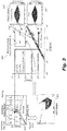
- the control module 109 can be configured to determine process parameters (e.g., laser power, pulsing rate, x-y scan speed, transducer amplitude and/or frequency) as a function of one or more models for a selected powder chemistry.
- process parameters e.g., laser power, pulsing rate, x-y scan speed, transducer amplitude and/or frequency
- the control module 109 can use a computational fluid dynamics (CFD) model 301 (e.g., to compute temperature gradient G and solidification speed V from process parameter), a defect model 303 (e.g., for determining a proper scan speed vs.
- CFD computational fluid dynamics
- control module 109 can be configured to utilize one or more of the above models in any suitable manner, and/or or to use any other suitable models, to form an amorphous structure.
- the powder used can be selected to be able to create an amorphous structure.
- materials that can form an amorphous structure include, but are not limited to, aluminum and titanium based structures for example.
- the control module 109 can be configured to create articles with different characteristics in different portions thereof.
- one layer can be amorphous, and another other layer can have grains.
- outer layer or layers of an article can amorphous and/or have nanocrystal grains) while the bulk can be normally manufactured to have a bulk or regular material.
- a non-transitory computer readable medium comprising computer executable instructions configured to cause a computer perform a method.
- the method can include any suitable method disclosed herein.
- the method can include controlling an energy applicator (e.g., as disclosed above) of an additive manufacturing machine to create an amorphous structure forming at least a portion of the article.
- the method can include pulsing the laser.
- the method can include controlling the laser to cause an amorphous matrix formation cooling rate (e.g., as disclosed above) to form an amorphous matrix.
- the method can further include controlling one or more acoustic transducers disposed on or in a build platform to provide vibration during additive manufacturing to an article and/or a portion thereof being built to cause formation of nanocrystal grains in the amorphous matrix.
- the method can include controlling a plurality of transducers independently of each other to produce vibration in a predetermined location of the build platform.
- a method can include additively manufacturing an article that includes an amorphous structure in at least a portion of the article.
- the method can include heating a powder and allowing the heated powder to cool at an amorphous matrix formation rate.
- the method can include vibrating the heated powder during heating and/or after heating to form nanocrystal grains in an amorphous matrix. Vibrating can include vibrating at one or more ultrasonic frequencies. Vibrating can include vibrating an entire build area or vibrating a local portion being heated.
- the method can include any other suitable method(s) and/or portion(s) thereof.
- amorphous structure or metal glass have shown excellent elastic strain, and fracture resistance but tend to be more brittle.
- a hybrid structure with crystalline grains in amorphous matrix can be used to accommodate some plastic strain and imparts ductility while maintaining high fatigue resistance and elastic strain.
- Embodiments can create nanocrystalline grain structures using ultrasonic assisted pulsed laser based directed energy deposition. Embodiments can use process models to obtain a hybrid structure containing nanocrystalline grains in amorphous matrix through ultrasonic assisted pulsed laser.
- the pulsed laser can fabricate an amorphous matrix through a phase field-model predicted process region where cooling rate is higher than a suitable rate, e.g., as disclosed above.
- Ultrasonic vibration can be induced at layer level and/or within the process zone to specifically break the solidification front and create additional seeds at layer level or just within the process zone. This will form nanocrystalline grains in the amorphous matrix.
- An arrangement of transducers can be included in build platform to induce crystalline transition locally in a regular array.
- Embodiments can utilize a pulsed laser with a controlled scan strategy to create amorphous microstructure, while an ultrasonic assisted laser engineered net shaping (LENS) process can refine grain structure. Ultrasonic vibration can break the growing dendrites and create seeds at multiple locations within the melt pool, thus refining grain structure and resulting in nanocrystalline grains. Thus embodiments include additive manufacturing methods for minimizing brittleness of deposited amorphous materials by introducing nanocrystalline microstructure. Embodiments can use a physics-driven model assisted process map to create a hybrid structure comprised of nanocrystalline structure in amorphous matrix. Embodiments can utilize an arrangement of multiple powder nozzles (e.g., in directed energy deposition process) that can feed a different composition of materials at bulk, near surface, and at surface.
- LENS ultrasonic assisted laser engineered net shaping
- Embodiments can be applied to any suitable field of structures, e.g., aerospace structures for example.
- a fan blade can be manufactured to have outer layers be amorphous, while a bulk material is of normal composition.
- this disclosure can be applied to the fabrication of strain wave gears with high transmission ratio and actuators as well as for aero-structures and vehicle components.
- Embodiments can be used for light weighting while improving the performance (e.g., fatigue and yield properties improvements with grain refinement).
- aspects of the present disclosure may be embodied as a system, method or computer program product. Accordingly, aspects of this disclosure may take the form of an entirely hardware embodiment, an entirely software embodiment (including firmware, resident software, micro-code, etc.), or an embodiment combining software and hardware aspects, all possibilities of which can be referred to herein as a "circuit,” “module,” or “system.”
- a “circuit,” “module,” or “system” can include one or more portions of one or more separate physical hardware and/or software components that can together perform the disclosed function of the "circuit,” “module,” or “system”, or a “circuit,” “module,” or “system” can be a single self-contained unit (e.g., of hardware and/or software).
- aspects of this disclosure may take the form of a computer program product embodied in one or more computer readable medium(s) having computer readable program code embodied thereon.
- the computer readable medium may be a computer readable signal medium or a computer readable storage medium.
- a computer readable storage medium may be, for example, but not limited to, an electronic, magnetic, optical, electromagnetic, infrared, or semiconductor system, apparatus, or device, or any suitable combination of the foregoing.
- a computer readable storage medium may be any tangible medium that can contain, or store a program for use by or in connection with an instruction execution system, apparatus, or device.
- a computer readable signal medium may include a propagated data signal with computer readable program code embodied therein, for example, in baseband or as part of a carrier wave. Such a propagated signal may take any of a variety of forms, including, but not limited to, electro-magnetic, optical, or any suitable combination thereof.
- a computer readable signal medium may be any computer readable medium that is not a computer readable storage medium and that can communicate, propagate, or transport a program for use by or in connection with an instruction execution system, apparatus, or device.
- Program code embodied on a computer readable medium may be transmitted using any appropriate medium, including but not limited to wireless, wireline, optical fiber cable, RF, etc., or any suitable combination of the foregoing.
- Computer program code for carrying out operations for aspects of this disclosure may be written in any combination of one or more programming languages, including an object oriented programming language such as Java, Smalltalk, C++ or the like and conventional procedural programming languages, such as the "C" programming language or similar programming languages.
- the program code may execute entirely on the user's computer, partly on the user's computer, as a stand-alone software package, partly on the user's computer and partly on a remote computer or entirely on the remote computer or server.
- the remote computer may be connected to the user's computer through any type of network, including a local area network (LAN) or a wide area network (WAN), or the connection may be made to an external computer (for example, through the Internet using an Internet Service Provider).
- LAN local area network
- WAN wide area network
- Internet Service Provider for example, AT&T, MCI, Sprint, EarthLink, MSN, GTE, etc.
- These computer program instructions may also be stored in a computer readable medium that can direct a computer, other programmable data processing apparatus, or other devices to function in a particular manner, such that the instructions stored in the computer readable medium produce an article of manufacture including instructions which implement the function/act specified in the flowchart and/or block diagram block or blocks.
- the computer program instructions may also be loaded onto a computer, other programmable data processing apparatus, or other devices to cause a series of operational steps to be performed on the computer, other programmable apparatus or other devices to produce a computer implemented process such that the instructions which execute on the computer or other programmable apparatus provide processes for implementing the functions/acts specified herein.
- any numerical values disclosed herein can be exact values or can be values within a range. Further, any terms of approximation (e.g., “about”, “approximately”, “around”) used in this disclosure can mean the stated value within a range. For example, in certain embodiments, the range can be within (plus or minus) 20%, or within 10%, or within 5%, or within 2%, or within any other suitable percentage or number as appreciated by those having ordinary skill in the art (e.g., for known tolerance limits or error ranges).
- a reference to "A and/or B", when used in conjunction with open-ended language such as “comprising” can refer, in one embodiment, to A only (optionally including elements other than B); in another embodiment, to B only (optionally including elements other than A); in yet another embodiment, to both A and B (optionally including other elements); etc.
Landscapes
- Engineering & Computer Science (AREA)
- Chemical & Material Sciences (AREA)
- Materials Engineering (AREA)
- Physics & Mathematics (AREA)
- Optics & Photonics (AREA)
- Manufacturing & Machinery (AREA)
- Mechanical Engineering (AREA)
- Plasma & Fusion (AREA)
- Health & Medical Sciences (AREA)
- Toxicology (AREA)
- General Health & Medical Sciences (AREA)
- Powder Metallurgy (AREA)
Abstract
Description
- This disclosure relates to additive manufacturing, more specifically to additive manufacturing of amorphous structures.
- Alloys used in additive manufacturing are primarily of polycrystalline/equiaxed microstructure with yield strength and fatigue resistance being the most sought after properties. However, the presence of defects and inhomogeneity in the as-built structure necessitates use of post-processing (e.g., heat treatment, HIP) that causes grain growth.
- Such conventional methods and systems have generally been considered satisfactory for their intended purpose. However, there is still a need in the art for improved additive manufacturing systems and methods. The present disclosure provides a solution for this need.
- An additive manufacturing system configured to additively build an article can include an energy applicator, a build platform, and a powder nozzle configured to eject powder toward the build platform to be acted on by the energy applicator. The system can include a control module configured to control the energy applicator to create an amorphous structure forming at least a portion of the article.
- The energy applicator can include a laser. The control module can be configured to pulse the laser. The control module can be configured to control the laser to cause an amorphous matrix formation cooling rate to form an amorphous matrix. The amorphous matrix formation cooling rate can be about 105 K/s to about 106 K/s or even higher, for example.
- The energy applicator can include one or more acoustic transducers disposed on or in the build platform to provide vibration during additive manufacturing to the article and/or a portion thereof to cause formation of nanocrystal grains in the amorphous matrix. The one or more acoustic transducers can include a plurality of ultrasonic transducers. The plurality of transducers can be disposed in an array on or in the build platform. The control module can be configured to control the plurality of transducers independently of each other to produce vibration in a predetermined location of the build platform.
- In accordance with at least one aspect of this disclosure, a non-transitory computer readable medium comprising computer executable instructions configured to cause a computer perform a method. The method can include any suitable method disclosed herein. For example, the method can include controlling an energy applicator (e.g., as disclosed above) of an additive manufacturing machine to create an amorphous structure forming at least a portion of the article.
- The method can include pulsing the laser. The method can include controlling the laser to cause an amorphous matrix formation cooling rate (e.g., as disclosed above) to form an amorphous matrix.
- The method can further include controlling one or more acoustic transducers disposed on or in a build platform to provide vibration during additive manufacturing to an article and/or a portion thereof being built to cause formation of nanocrystal grains in the amorphous matrix. The method can include controlling a plurality of transducers independently of each other to produce vibration in a predetermined location of the build platform.
- In accordance with at least one aspect of this disclosure, a method can include additively manufacturing an article that includes an amorphous structure in at least a portion of the article. The method can include heating a powder and allowing the heated powder to cool at an amorphous matrix formation rate.
- The method can include vibrating the heated powder during heating and/or after heating to form nanocrystal grains in an amorphous matrix. Vibrating can include vibrating at one or more ultrasonic frequencies. Vibrating can include vibrating an entire build area or vibrating a local portion being heated.
- These and other features of the embodiments of the subject disclosure will become more readily apparent to those skilled in the art from the following detailed description taken in conjunction with the drawings.
- So that those skilled in the art to which the subject disclosure appertains will readily understand how to make and use the devices and methods of the subject disclosure without undue experimentation, embodiments thereof will be described in detail herein below with reference to certain figures, wherein:
-
Fig. 1 is a schematic diagram of an embodiment of a system in accordance with this disclosure; -
Fig. 2 is a schematic diagram of an embodiment of a transducer array in a build platform of the system ofFig. 1 ; and -
Fig. 3 shows a schematic diagram illustrating the use, e.g., by a control module, of computation fluid dynamics (CFD), a defect process map, a solidification map and phase field model to identify process zones and parameters that form amorphous microstructure. - Reference will now be made to the drawings wherein like reference numerals identify similar structural features or aspects of the subject disclosure. For purposes of explanation and illustration, and not limitation, an illustrative view of an embodiment of a system in accordance with the disclosure is shown in
Fig. 1 and is designated generally by reference character 100. Other embodiments and/or aspects of this disclosure are shown inFigs. 2 and3 . Certain embodiments described herein can be used to produce one or more articles having amorphous structure (e.g., amorphous matrix with nanocrystal grains) forming at least a portion of the article (e.g., an outer surface thereof). - Referring to
Fig. 1 , an additive manufacturing system 100 configured to additively build an article (not shown) can include an energy applicator (e.g., comprised oflaser 101 and transducer 103). The system 100 can include abuild platform 105 and apowder nozzle 107 configured to eject powder (e.g., metal powder) toward thebuild platform 105 to be acted on by the energy applicator (e.g., heated and/or vibrated). - The system 100 can include a
control module 109 configured to control the energy applicator (e.g.,laser 101 and/or transducer 103) to create an amorphous structure forming at least a portion of the article. The amorphous structure can be a structure in which at least a portion (e.g., the entirety, an out surface thereof, etc.) can have an amorphous matrix as appreciated by those having ordinary skill in the art. In certain embodiments, the amorphous structure can include nanocrystalline grains disposed within the amorphous matrix (e.g., in any suitable proportion). In certain embodiments, there may be no nanocrystalline grains. Thecontrol module 109 can include any suitable hardware and/or software module(s) in accordance with this disclosure and/or as appreciated by those having ordinary skill in the art. - The energy applicator can include a
laser 101, for example. Any other suitable heat source (e.g., an electron beam) is contemplated herein. Thecontrol module 109 can be configured to pulse the laser, for example. Thecontrol module 109 can be configured to control thelaser 101 to cause an amorphous matrix formation cooling rate to form an amorphous matrix. The amorphous matrix formation cooling rate can be about 105 K/s to about 106 K/s or higher, for example. Therefore, thecontrol module 109 can be configured to pulse thelaser 101 and/or control power output of the laser to maintain a suitable cooling rate to achieve an amorphous matrix. - The energy applicator can also include one or more
acoustic transducers 103 disposed on or in thebuild platform 105 to provide vibration during additive manufacturing to the article and/or a portion thereof to cause formation of nanocrystal grains in the amorphous matrix. Referring additionally toFig. 2 , the one or moreacoustic transducers 103 can include a plurality ofultrasonic transducers 111, for example. The plurality oftransducers 111 can be disposed in an array (e.g., as shown in rows and columns) on or in thebuild platform 105. Thecontrol module 109 can be configured to control the plurality of transducers 111 (e.g., at least two thereof) independently of each other to produce vibration (e.g., about 50 KHz and up) in a predetermined location (e.g., where the location of heat application is) of thebuild platform 105. - The
control module 109 can be operatively connected to apower supply 113 that provides power to transducer 103 to control the output power and/or frequency of thetransducer 103. Any other suitable arrangement is contemplated herein for thecontrol module 109 to control thetransducer 103. - The system 100 can include any suitable number of
powder nozzles 107 and can use any suitable powder or combinations thereof to form an amorphous structure (e.g., with nanocrystal grains). Referring additionally toFig. 3 , thecontrol module 109 can be configured to determine process parameters (e.g., laser power, pulsing rate, x-y scan speed, transducer amplitude and/or frequency) as a function of one or more models for a selected powder chemistry. For example, thecontrol module 109 can use a computational fluid dynamics (CFD) model 301 (e.g., to compute temperature gradient G and solidification speed V from process parameter), a defect model 303 (e.g., for determining a proper scan speed vs. power), a microstructure transition model 305 (e.g., for determining the effects of solidification speed V and cooling gradient G), and a phase field model 307 (e.g., for determining whether the final material is amorphous). Thecontrol module 109 can be configured to utilize one or more of the above models in any suitable manner, and/or or to use any other suitable models, to form an amorphous structure. - The powder used can be selected to be able to create an amorphous structure. For example, materials that can form an amorphous structure include, but are not limited to, aluminum and titanium based structures for example.
- The
control module 109 can be configured to create articles with different characteristics in different portions thereof. For example, one layer can be amorphous, and another other layer can have grains. In certain embodiments, and outer layer or layers of an article can amorphous and/or have nanocrystal grains) while the bulk can be normally manufactured to have a bulk or regular material. - In accordance with at least one aspect of this disclosure, a non-transitory computer readable medium comprising computer executable instructions configured to cause a computer perform a method. The method can include any suitable method disclosed herein. For example, the method can include controlling an energy applicator (e.g., as disclosed above) of an additive manufacturing machine to create an amorphous structure forming at least a portion of the article.
- The method can include pulsing the laser. The method can include controlling the laser to cause an amorphous matrix formation cooling rate (e.g., as disclosed above) to form an amorphous matrix.
- The method can further include controlling one or more acoustic transducers disposed on or in a build platform to provide vibration during additive manufacturing to an article and/or a portion thereof being built to cause formation of nanocrystal grains in the amorphous matrix. The method can include controlling a plurality of transducers independently of each other to produce vibration in a predetermined location of the build platform.
- In accordance with at least one aspect of this disclosure, a method can include additively manufacturing an article that includes an amorphous structure in at least a portion of the article. The method can include heating a powder and allowing the heated powder to cool at an amorphous matrix formation rate.
- The method can include vibrating the heated powder during heating and/or after heating to form nanocrystal grains in an amorphous matrix. Vibrating can include vibrating at one or more ultrasonic frequencies. Vibrating can include vibrating an entire build area or vibrating a local portion being heated. The method can include any other suitable method(s) and/or portion(s) thereof.
- Traditional final microstructures can contain larger grain size than forged counterpart, resulting in reduction of yield strength and fatigue resistance. On the other hand, amorphous structure or metal glass have shown excellent elastic strain, and fracture resistance but tend to be more brittle. A hybrid structure with crystalline grains in amorphous matrix can be used to accommodate some plastic strain and imparts ductility while maintaining high fatigue resistance and elastic strain.
- Embodiments can create nanocrystalline grain structures using ultrasonic assisted pulsed laser based directed energy deposition. Embodiments can use process models to obtain a hybrid structure containing nanocrystalline grains in amorphous matrix through ultrasonic assisted pulsed laser.
- The pulsed laser can fabricate an amorphous matrix through a phase field-model predicted process region where cooling rate is higher than a suitable rate, e.g., as disclosed above. Ultrasonic vibration can be induced at layer level and/or within the process zone to specifically break the solidification front and create additional seeds at layer level or just within the process zone. This will form nanocrystalline grains in the amorphous matrix. An arrangement of transducers can be included in build platform to induce crystalline transition locally in a regular array.
- Embodiments can utilize a pulsed laser with a controlled scan strategy to create amorphous microstructure, while an ultrasonic assisted laser engineered net shaping (LENS) process can refine grain structure. Ultrasonic vibration can break the growing dendrites and create seeds at multiple locations within the melt pool, thus refining grain structure and resulting in nanocrystalline grains. Thus embodiments include additive manufacturing methods for minimizing brittleness of deposited amorphous materials by introducing nanocrystalline microstructure. Embodiments can use a physics-driven model assisted process map to create a hybrid structure comprised of nanocrystalline structure in amorphous matrix. Embodiments can utilize an arrangement of multiple powder nozzles (e.g., in directed energy deposition process) that can feed a different composition of materials at bulk, near surface, and at surface.
- Embodiments can be applied to any suitable field of structures, e.g., aerospace structures for example. For example, a fan blade can be manufactured to have outer layers be amorphous, while a bulk material is of normal composition. For example, this disclosure can be applied to the fabrication of strain wave gears with high transmission ratio and actuators as well as for aero-structures and vehicle components. Embodiments can be used for light weighting while improving the performance (e.g., fatigue and yield properties improvements with grain refinement).
- As will be appreciated by those skilled in the art, aspects of the present disclosure may be embodied as a system, method or computer program product. Accordingly, aspects of this disclosure may take the form of an entirely hardware embodiment, an entirely software embodiment (including firmware, resident software, micro-code, etc.), or an embodiment combining software and hardware aspects, all possibilities of which can be referred to herein as a "circuit," "module," or "system." A "circuit," "module," or "system" can include one or more portions of one or more separate physical hardware and/or software components that can together perform the disclosed function of the "circuit," "module," or "system", or a "circuit," "module," or "system" can be a single self-contained unit (e.g., of hardware and/or software). Furthermore, aspects of this disclosure may take the form of a computer program product embodied in one or more computer readable medium(s) having computer readable program code embodied thereon.
- Any combination of one or more computer readable medium(s) may be utilized. The computer readable medium may be a computer readable signal medium or a computer readable storage medium. A computer readable storage medium may be, for example, but not limited to, an electronic, magnetic, optical, electromagnetic, infrared, or semiconductor system, apparatus, or device, or any suitable combination of the foregoing. More specific examples (a non-exhaustive list) of the computer readable storage medium would include the following: an electrical connection having one or more wires, a portable computer diskette, a hard disk, a random access memory (RAM), a read-only memory (ROM), an erasable programmable read-only memory (EPROM or Flash memory), an optical fiber, a portable compact disc read-only memory (CD-ROM), an optical storage device, a magnetic storage device, or any suitable combination of the foregoing. In the context of this document, a computer readable storage medium may be any tangible medium that can contain, or store a program for use by or in connection with an instruction execution system, apparatus, or device.
- A computer readable signal medium may include a propagated data signal with computer readable program code embodied therein, for example, in baseband or as part of a carrier wave. Such a propagated signal may take any of a variety of forms, including, but not limited to, electro-magnetic, optical, or any suitable combination thereof. A computer readable signal medium may be any computer readable medium that is not a computer readable storage medium and that can communicate, propagate, or transport a program for use by or in connection with an instruction execution system, apparatus, or device.
- Program code embodied on a computer readable medium may be transmitted using any appropriate medium, including but not limited to wireless, wireline, optical fiber cable, RF, etc., or any suitable combination of the foregoing.
- Computer program code for carrying out operations for aspects of this disclosure may be written in any combination of one or more programming languages, including an object oriented programming language such as Java, Smalltalk, C++ or the like and conventional procedural programming languages, such as the "C" programming language or similar programming languages. The program code may execute entirely on the user's computer, partly on the user's computer, as a stand-alone software package, partly on the user's computer and partly on a remote computer or entirely on the remote computer or server. In the latter scenario, the remote computer may be connected to the user's computer through any type of network, including a local area network (LAN) or a wide area network (WAN), or the connection may be made to an external computer (for example, through the Internet using an Internet Service Provider).
- Aspects of the this disclosure may be described above with reference to flowchart illustrations and/or block diagrams of methods, apparatus (systems) and computer program products according to embodiments of this disclosure. It will be understood that each block of any flowchart illustrations and/or block diagrams, and combinations of blocks in any flowchart illustrations and/or block diagrams, can be implemented by computer program instructions. These computer program instructions may be provided to a processor of a general purpose computer, special purpose computer, or other programmable data processing apparatus to produce a machine, such that the instructions, which execute via the processor of the computer or other programmable data processing apparatus, create means for implementing the functions/acts specified in any flowchart and/or block diagram block or blocks.
- These computer program instructions may also be stored in a computer readable medium that can direct a computer, other programmable data processing apparatus, or other devices to function in a particular manner, such that the instructions stored in the computer readable medium produce an article of manufacture including instructions which implement the function/act specified in the flowchart and/or block diagram block or blocks.
- The computer program instructions may also be loaded onto a computer, other programmable data processing apparatus, or other devices to cause a series of operational steps to be performed on the computer, other programmable apparatus or other devices to produce a computer implemented process such that the instructions which execute on the computer or other programmable apparatus provide processes for implementing the functions/acts specified herein.
- Those having ordinary skill in the art understand that any numerical values disclosed herein can be exact values or can be values within a range. Further, any terms of approximation (e.g., "about", "approximately", "around") used in this disclosure can mean the stated value within a range. For example, in certain embodiments, the range can be within (plus or minus) 20%, or within 10%, or within 5%, or within 2%, or within any other suitable percentage or number as appreciated by those having ordinary skill in the art (e.g., for known tolerance limits or error ranges).
- The articles "a", "an", and "the" as used herein and in the appended claims are used herein to refer to one or to more than one (i.e., to at least one) of the grammatical object of the article unless the context clearly indicates otherwise. By way of example, "an element" means one element or more than one element.
- The phrase "and/or," as used herein in the specification and in the claims, should be understood to mean "either or both" of the elements so conjoined, i.e., elements that are conjunctively present in some cases and disjunctively present in other cases. Multiple elements listed with "and/or" should be construed in the same fashion, i.e., "one or more" of the elements so conjoined. Other elements may optionally be present other than the elements specifically identified by the "and/or" clause, whether related or unrelated to those elements specifically identified. Thus, as a non-limiting example, a reference to "A and/or B", when used in conjunction with open-ended language such as "comprising" can refer, in one embodiment, to A only (optionally including elements other than B); in another embodiment, to B only (optionally including elements other than A); in yet another embodiment, to both A and B (optionally including other elements); etc.
- As used herein in the specification and in the claims, "or" should be understood to have the same meaning as "and/or" as defined above. For example, when separating items in a list, "or" or "and/or" shall be interpreted as being inclusive, i.e., the inclusion of at least one, but also including more than one, of a number or list of elements, and, optionally, additional unlisted items. Only terms clearly indicated to the contrary, such as "only one of' or "exactly one of," or, when used in the claims, "consisting of," will refer to the inclusion of exactly one element of a number or list of elements. In general, the term "or" as used herein shall only be interpreted as indicating exclusive alternatives (i.e., "one or the other but not both") when preceded by terms of exclusivity, such as "either," "one of," "only one of," or "exactly one of."
- Any suitable combination(s) of any disclosed embodiments and/or any suitable portion(s) thereof are contemplated herein as appreciated by those having ordinary skill in the art in view of this disclosure.
- The embodiments of the present disclosure, as described above and shown in the drawings, provide for improvement in the art to which they pertain. While the subject disclosure includes reference to certain embodiments, those skilled in the art will readily appreciate that changes and/or modifications may be made thereto without departing from the spirit and scope of the invention as defined by the claims.
Claims (15)
- An additive manufacturing system configured to additively build an article, comprising:an energy applicator (101);a build platform (105);a powder nozzle (107) configured to eject powder toward the build platform to be acted on by the energy applicator; anda control module (109) configured to control the energy applicator to create an amorphous structure forming at least a portion of the article.
- The system of claim 1, wherein the energy applicator includes a laser (101).
- The system of claim 2, wherein the control module is configured to pulse the laser.
- The system of claim 3, wherein the control module is configured to control the laser to cause an amorphous matrix formation cooling rate to form an amorphous matrix.
- The system of claim 4, wherein the amorphous matrix formation cooling rate is about 105 K/s to about 106 K/s or higher.
- The system of claim 4 OR 5, wherein the energy applicator includes one or more acoustic transducers (103) disposed on or in the build platform to provide vibration during additive manufacturing to the article and/or a portion thereof to cause formation of nanocrystal grains in the amorphous matrix.
- The system of claim 6, wherein the one or more acoustic transducers include a plurality of ultrasonic transducers, and optionally wherein the plurality of transducers are disposed in an array on or in the build platform, and optionally wherein the control module is configured to control the plurality of transducers independently of each other to produce vibration in a predetermined location of the build platform.
- A non-transitory computer readable medium comprising computer executable instructions configured to cause a computer perform a method, the method comprising:
controlling an energy applicator of an additive manufacturing machine to create an amorphous structure forming at least a portion of the article. - The non-transitory computer readable medium of claim 8, wherein the energy applicator includes a laser, wherein the method includes pulsing the laser, and optionally wherein the method includes controlling the laser to cause an amorphous matrix formation cooling rate to form an amorphous matrix.
- The non-transitory computer readable medium of claim 9, wherein the amorphous matrix formation cooling rate is about 105 K/s to about 106 K/s or even higher.
- The non-transitory computer readable medium of claim 9 or 10, wherein the method further includes controlling one or more acoustic transducers disposed on or in a build platform to provide vibration during additive manufacturing to an article and/or a portion thereof being built to cause formation of nanocrystal grains in the amorphous matrix, and optionally wherein the one or more acoustic transducers include a plurality of ultrasonic transducers, wherein the plurality of transducers are disposed in an array on or in the build platform, wherein the method includes controlling the plurality of transducers independently of each other to produce vibration in a predetermined location of the build platform.
- A method, comprising:
additively manufacturing an article that includes an amorphous structure in at least a portion of the article. - The method of claim 12, wherein the method includes heating a powder and allowing the heated powder to cool at an amorphous matrix formation rate.
- The method of claim 13, further comprising vibrating the heated powder during heating and/or after heating to form nanocrystal grains in an amorphous matrix, and optionally wherein vibrating includes vibrating an entire build area or vibrating a local portion being heated.
- The method of claim 14, wherein vibrating includes vibrating at one or more ultrasonic frequency.
Applications Claiming Priority (1)
| Application Number | Priority Date | Filing Date | Title |
|---|---|---|---|
| US16/657,420 US11214002B2 (en) | 2019-10-18 | 2019-10-18 | Additively manufacturing of amorphous structures |
Publications (1)
| Publication Number | Publication Date |
|---|---|
| EP3808476A1 true EP3808476A1 (en) | 2021-04-21 |
Family
ID=68916269
Family Applications (1)
| Application Number | Title | Priority Date | Filing Date |
|---|---|---|---|
| EP19215822.8A Pending EP3808476A1 (en) | 2019-10-18 | 2019-12-12 | Additively manufacturing of amorphous structures |
Country Status (2)
| Country | Link |
|---|---|
| US (2) | US11214002B2 (en) |
| EP (1) | EP3808476A1 (en) |
Cited By (2)
| Publication number | Priority date | Publication date | Assignee | Title |
|---|---|---|---|---|
| EP4223438A1 (en) * | 2022-02-04 | 2023-08-09 | Goodrich Corporation | Producing ultra-fine-grained materials using additive manufacturing |
| EP4477340A1 (en) * | 2023-06-13 | 2024-12-18 | RTX Corporation | Additive manufacturing method for production of hierarchical design optimized composite materials |
Families Citing this family (1)
| Publication number | Priority date | Publication date | Assignee | Title |
|---|---|---|---|---|
| US12358212B2 (en) | 2022-02-09 | 2025-07-15 | Lawrence Livermore National Security, Llc | System and method for ultrasound-induced additive manufacturing of polymers and composites |
Citations (5)
| Publication number | Priority date | Publication date | Assignee | Title |
|---|---|---|---|---|
| US20170014907A1 (en) * | 2015-07-17 | 2017-01-19 | Applied Materials, Inc. | Brace structures for additive manufacturing |
| US20170173692A1 (en) * | 2015-12-16 | 2017-06-22 | Desktop Metal, Inc. | Metal printer with vibrating ultrasound nozzle |
| US20170252851A1 (en) * | 2016-03-02 | 2017-09-07 | Desktop Metal, Inc. | Additive manufacturing with metallic composites |
| CN108136663A (en) * | 2015-05-14 | 2018-06-08 | 开发者2有限公司 | Increasing material manufacturing device and method |
| US20180304500A1 (en) * | 2015-10-21 | 2018-10-25 | Uab "Neurotechnology" | Contactless manipulation apparatus, assembly method and 3d printing |
Family Cites Families (15)
| Publication number | Priority date | Publication date | Assignee | Title |
|---|---|---|---|---|
| US5387380A (en) * | 1989-12-08 | 1995-02-07 | Massachusetts Institute Of Technology | Three-dimensional printing techniques |
| JP3551838B2 (en) * | 1999-05-26 | 2004-08-11 | 松下電工株式会社 | Manufacturing method of three-dimensional shaped object |
| EP2495056A1 (en) * | 2011-03-01 | 2012-09-05 | Siemens Aktiengesellschaft | Laser build up method using vibration and apparatus |
| WO2013112217A2 (en) | 2011-10-31 | 2013-08-01 | California Institute Of Technology | Methods for fabricating gradient alloy articles with multi-functional properties |
| US9579718B2 (en) * | 2013-01-24 | 2017-02-28 | California Institute Of Technology | Systems and methods for fabricating objects including amorphous metal using techniques akin to additive manufacturing |
| EP3096905B1 (en) * | 2014-01-20 | 2021-12-22 | Raytheon Technologies Corporation | A method of additive manufacturing utilizing an epitaxy process |
| EP3096906A4 (en) * | 2014-01-22 | 2017-03-08 | United Technologies Corporation | Additive manufacturing system and method of operation |
| JP5951672B2 (en) * | 2014-03-31 | 2016-07-13 | 株式会社東芝 | Laminate manufacturing apparatus and manufacturing method |
| US10556270B2 (en) * | 2014-05-01 | 2020-02-11 | United Technologies Corporation | Additive manufacturing system for minimizing thermal stresses |
| CN104084216B (en) | 2014-07-16 | 2016-03-30 | 西北工业大学 | A kind of silver-copper nano alloy eelctro-catalyst and laser Gaseous deposition process thereof |
| JP6347394B2 (en) * | 2014-10-01 | 2018-06-27 | パナソニックIpマネジメント株式会社 | Manufacturing method of three-dimensional shaped object |
| US9527165B2 (en) * | 2015-02-05 | 2016-12-27 | Siemens Energy, Inc. | Powder deposition process utilizing vibratory mechanical energy |
| CN106011847B (en) * | 2016-07-22 | 2019-02-05 | 江苏大学 | A kind of in-situ amorphization modification method of metal material surface |
| WO2018187900A1 (en) * | 2017-04-10 | 2018-10-18 | Shenzhen University | System and method for fabrication of bulk nanocrystal alloy |
| KR101921281B1 (en) | 2017-12-01 | 2018-11-22 | 선문대학교 산학협력단 | Method for manufacturing article using additive manufacturing and surface treatment |
-
2019
- 2019-10-18 US US16/657,420 patent/US11214002B2/en active Active
- 2019-12-12 EP EP19215822.8A patent/EP3808476A1/en active Pending
-
2021
- 2021-12-31 US US17/566,928 patent/US11701821B2/en active Active
Patent Citations (5)
| Publication number | Priority date | Publication date | Assignee | Title |
|---|---|---|---|---|
| CN108136663A (en) * | 2015-05-14 | 2018-06-08 | 开发者2有限公司 | Increasing material manufacturing device and method |
| US20170014907A1 (en) * | 2015-07-17 | 2017-01-19 | Applied Materials, Inc. | Brace structures for additive manufacturing |
| US20180304500A1 (en) * | 2015-10-21 | 2018-10-25 | Uab "Neurotechnology" | Contactless manipulation apparatus, assembly method and 3d printing |
| US20170173692A1 (en) * | 2015-12-16 | 2017-06-22 | Desktop Metal, Inc. | Metal printer with vibrating ultrasound nozzle |
| US20170252851A1 (en) * | 2016-03-02 | 2017-09-07 | Desktop Metal, Inc. | Additive manufacturing with metallic composites |
Cited By (3)
| Publication number | Priority date | Publication date | Assignee | Title |
|---|---|---|---|---|
| EP4223438A1 (en) * | 2022-02-04 | 2023-08-09 | Goodrich Corporation | Producing ultra-fine-grained materials using additive manufacturing |
| US12172213B2 (en) | 2022-02-04 | 2024-12-24 | Goodrich Corporation | Producing ultra-fine-grained materials using additive manufacturing |
| EP4477340A1 (en) * | 2023-06-13 | 2024-12-18 | RTX Corporation | Additive manufacturing method for production of hierarchical design optimized composite materials |
Also Published As
| Publication number | Publication date |
|---|---|
| US20220126511A1 (en) | 2022-04-28 |
| US11701821B2 (en) | 2023-07-18 |
| US11214002B2 (en) | 2022-01-04 |
| US20210114292A1 (en) | 2021-04-22 |
Similar Documents
| Publication | Publication Date | Title |
|---|---|---|
| US11701821B2 (en) | Additively manufacturing of amorphous structures | |
| Özel et al. | A review on wire-fed directed energy deposition based metal additive manufacturing | |
| JP2019526704A (en) | Method and system including additive manufacturing, and additive manufactured articles | |
| Shi et al. | Integrated Simulation Framework for Additively Manufactured Ti-6Al-4V: Melt Pool Dynamics, Microstructure, Solid-State Phase Transformation, and Microelastic Response: Shi, Khairallah, Heo, Rolchigo, McKeown, and Matthews | |
| CN105026076B (en) | Apparatus and method for producing workpieces with customized microstructures | |
| Buehler et al. | Mechanical behavior of nanocomposites | |
| Wang et al. | Electron backscatter diffraction analysis of Inconel 718 parts fabricated by selective laser melting additive manufacturing | |
| US11666973B2 (en) | Complex concentrated alloy and high entropy alloy additive manufacturing systems and methods | |
| US11534960B2 (en) | Method for additively manufacturing a component augmented by ultrasonic excitation and active temperature control | |
| CN212310848U (en) | Thermal processing equipment for PBF-based three-dimensional (3D) printer | |
| US20250065409A1 (en) | Producing ultra-fine-grained materials using additive manufacturing | |
| CN110860797A (en) | Electric arc-laser composite additive manufacturing method | |
| CN107932505B (en) | Optimal grinding task path planning method and device based on articulated arm robot | |
| CN105624669A (en) | Sectioned laser cladding remanufacturing method with preheating and heat treatment for complex parts | |
| Akinlabi et al. | Effect of scanning speed on material efficiency of laser metal deposited Ti6Al4V | |
| Liu et al. | Mathematical modeling of transport phenomena in multi-track and multi-layer laser powder deposition of single-crystal superalloy | |
| CN115971514A (en) | A fully isometric method for laser shock strengthening of aviation additive components | |
| US20140197139A1 (en) | Production of fine grains in deposition welding | |
| Zinoviev et al. | On the numerical simulation of the microstructural evolution induced by laser additive manufacturing of steel products | |
| CN113182530A (en) | Additive manufacturing method of magnesium alloy directional solidified crystal or single crystal | |
| CN109352984A (en) | Additive Manufacturing Methods and Related Components | |
| Wang et al. | Toolpath optimization in laser metal deposition for manufacturing thin-walled superalloy components based on deep reinforcement learning | |
| Platt et al. | Enhancing mechanical properties and isotropy in ultrasonic assisted powder bed fusion of metals using a laser beam (PBF-LB/M) via Dual Exposure | |
| CN112069702B (en) | Pulse laser 3D printing primary dendrite spacing prediction method, device and medium | |
| EP4477340A1 (en) | Additive manufacturing method for production of hierarchical design optimized composite materials |
Legal Events
| Date | Code | Title | Description |
|---|---|---|---|
| PUAI | Public reference made under article 153(3) epc to a published international application that has entered the european phase |
Free format text: ORIGINAL CODE: 0009012 |
|
| STAA | Information on the status of an ep patent application or granted ep patent |
Free format text: STATUS: THE APPLICATION HAS BEEN PUBLISHED |
|
| AK | Designated contracting states |
Kind code of ref document: A1 Designated state(s): AL AT BE BG CH CY CZ DE DK EE ES FI FR GB GR HR HU IE IS IT LI LT LU LV MC MK MT NL NO PL PT RO RS SE SI SK SM TR |
|
| AX | Request for extension of the european patent |
Extension state: BA ME |
|
| STAA | Information on the status of an ep patent application or granted ep patent |
Free format text: STATUS: REQUEST FOR EXAMINATION WAS MADE |
|
| 17P | Request for examination filed |
Effective date: 20211021 |
|
| RBV | Designated contracting states (corrected) |
Designated state(s): AL AT BE BG CH CY CZ DE DK EE ES FI FR GB GR HR HU IE IS IT LI LT LU LV MC MK MT NL NO PL PT RO RS SE SI SK SM TR |
|
| STAA | Information on the status of an ep patent application or granted ep patent |
Free format text: STATUS: EXAMINATION IS IN PROGRESS |
|
| 17Q | First examination report despatched |
Effective date: 20240131 |