EP3808247A1 - Simultaneous visible and fluorescence endoscopic imaging - Google Patents
Simultaneous visible and fluorescence endoscopic imaging Download PDFInfo
- Publication number
- EP3808247A1 EP3808247A1 EP20214764.1A EP20214764A EP3808247A1 EP 3808247 A1 EP3808247 A1 EP 3808247A1 EP 20214764 A EP20214764 A EP 20214764A EP 3808247 A1 EP3808247 A1 EP 3808247A1
- Authority
- EP
- European Patent Office
- Prior art keywords
- image data
- light
- visible
- fluorescence
- image
- Prior art date
- Legal status (The legal status is an assumption and is not a legal conclusion. Google has not performed a legal analysis and makes no representation as to the accuracy of the status listed.)
- Granted
Links
Images




Classifications
-
- A—HUMAN NECESSITIES
- A61—MEDICAL OR VETERINARY SCIENCE; HYGIENE
- A61B—DIAGNOSIS; SURGERY; IDENTIFICATION
- A61B1/00—Instruments for performing medical examinations of the interior of cavities or tubes of the body by visual or photographical inspection, e.g. endoscopes; Illuminating arrangements therefor
- A61B1/00002—Operational features of endoscopes
- A61B1/00004—Operational features of endoscopes characterised by electronic signal processing
- A61B1/00009—Operational features of endoscopes characterised by electronic signal processing of image signals during a use of endoscope
-
- A—HUMAN NECESSITIES
- A61—MEDICAL OR VETERINARY SCIENCE; HYGIENE
- A61B—DIAGNOSIS; SURGERY; IDENTIFICATION
- A61B1/00—Instruments for performing medical examinations of the interior of cavities or tubes of the body by visual or photographical inspection, e.g. endoscopes; Illuminating arrangements therefor
- A61B1/04—Instruments for performing medical examinations of the interior of cavities or tubes of the body by visual or photographical inspection, e.g. endoscopes; Illuminating arrangements therefor combined with photographic or television appliances
- A61B1/043—Instruments for performing medical examinations of the interior of cavities or tubes of the body by visual or photographical inspection, e.g. endoscopes; Illuminating arrangements therefor combined with photographic or television appliances for fluorescence imaging
-
- A—HUMAN NECESSITIES
- A61—MEDICAL OR VETERINARY SCIENCE; HYGIENE
- A61B—DIAGNOSIS; SURGERY; IDENTIFICATION
- A61B1/00—Instruments for performing medical examinations of the interior of cavities or tubes of the body by visual or photographical inspection, e.g. endoscopes; Illuminating arrangements therefor
- A61B1/04—Instruments for performing medical examinations of the interior of cavities or tubes of the body by visual or photographical inspection, e.g. endoscopes; Illuminating arrangements therefor combined with photographic or television appliances
- A61B1/045—Control thereof
-
- A—HUMAN NECESSITIES
- A61—MEDICAL OR VETERINARY SCIENCE; HYGIENE
- A61B—DIAGNOSIS; SURGERY; IDENTIFICATION
- A61B1/00—Instruments for performing medical examinations of the interior of cavities or tubes of the body by visual or photographical inspection, e.g. endoscopes; Illuminating arrangements therefor
- A61B1/04—Instruments for performing medical examinations of the interior of cavities or tubes of the body by visual or photographical inspection, e.g. endoscopes; Illuminating arrangements therefor combined with photographic or television appliances
- A61B1/05—Instruments for performing medical examinations of the interior of cavities or tubes of the body by visual or photographical inspection, e.g. endoscopes; Illuminating arrangements therefor combined with photographic or television appliances characterised by the image sensor, e.g. camera, being in the distal end portion
-
- A—HUMAN NECESSITIES
- A61—MEDICAL OR VETERINARY SCIENCE; HYGIENE
- A61B—DIAGNOSIS; SURGERY; IDENTIFICATION
- A61B1/00—Instruments for performing medical examinations of the interior of cavities or tubes of the body by visual or photographical inspection, e.g. endoscopes; Illuminating arrangements therefor
- A61B1/06—Instruments for performing medical examinations of the interior of cavities or tubes of the body by visual or photographical inspection, e.g. endoscopes; Illuminating arrangements therefor with illuminating arrangements
- A61B1/063—Instruments for performing medical examinations of the interior of cavities or tubes of the body by visual or photographical inspection, e.g. endoscopes; Illuminating arrangements therefor with illuminating arrangements for monochromatic or narrow-band illumination
-
- A—HUMAN NECESSITIES
- A61—MEDICAL OR VETERINARY SCIENCE; HYGIENE
- A61B—DIAGNOSIS; SURGERY; IDENTIFICATION
- A61B1/00—Instruments for performing medical examinations of the interior of cavities or tubes of the body by visual or photographical inspection, e.g. endoscopes; Illuminating arrangements therefor
- A61B1/06—Instruments for performing medical examinations of the interior of cavities or tubes of the body by visual or photographical inspection, e.g. endoscopes; Illuminating arrangements therefor with illuminating arrangements
- A61B1/0638—Instruments for performing medical examinations of the interior of cavities or tubes of the body by visual or photographical inspection, e.g. endoscopes; Illuminating arrangements therefor with illuminating arrangements providing two or more wavelengths
-
- A—HUMAN NECESSITIES
- A61—MEDICAL OR VETERINARY SCIENCE; HYGIENE
- A61B—DIAGNOSIS; SURGERY; IDENTIFICATION
- A61B1/00—Instruments for performing medical examinations of the interior of cavities or tubes of the body by visual or photographical inspection, e.g. endoscopes; Illuminating arrangements therefor
- A61B1/06—Instruments for performing medical examinations of the interior of cavities or tubes of the body by visual or photographical inspection, e.g. endoscopes; Illuminating arrangements therefor with illuminating arrangements
- A61B1/07—Instruments for performing medical examinations of the interior of cavities or tubes of the body by visual or photographical inspection, e.g. endoscopes; Illuminating arrangements therefor with illuminating arrangements using light-conductive means, e.g. optical fibres
-
- G—PHYSICS
- G01—MEASURING; TESTING
- G01N—INVESTIGATING OR ANALYSING MATERIALS BY DETERMINING THEIR CHEMICAL OR PHYSICAL PROPERTIES
- G01N21/00—Investigating or analysing materials by the use of optical means, i.e. using sub-millimetre waves, infrared, visible or ultraviolet light
- G01N21/62—Systems in which the material investigated is excited whereby it emits light or causes a change in wavelength of the incident light
- G01N21/63—Systems in which the material investigated is excited whereby it emits light or causes a change in wavelength of the incident light optically excited
- G01N21/64—Fluorescence; Phosphorescence
- G01N21/645—Specially adapted constructive features of fluorimeters
- G01N21/6456—Spatial resolved fluorescence measurements; Imaging
-
- G—PHYSICS
- G02—OPTICS
- G02B—OPTICAL ELEMENTS, SYSTEMS OR APPARATUS
- G02B23/00—Telescopes, e.g. binoculars; Periscopes; Instruments for viewing the inside of hollow bodies; Viewfinders; Optical aiming or sighting devices
- G02B23/24—Instruments or systems for viewing the inside of hollow bodies, e.g. fibrescopes
- G02B23/2407—Optical details
- G02B23/2461—Illumination
- G02B23/2469—Illumination using optical fibres
-
- G—PHYSICS
- G02—OPTICS
- G02B—OPTICAL ELEMENTS, SYSTEMS OR APPARATUS
- G02B23/00—Telescopes, e.g. binoculars; Periscopes; Instruments for viewing the inside of hollow bodies; Viewfinders; Optical aiming or sighting devices
- G02B23/24—Instruments or systems for viewing the inside of hollow bodies, e.g. fibrescopes
- G02B23/2476—Non-optical details, e.g. housings, mountings, supports
- G02B23/2484—Arrangements in relation to a camera or imaging device
-
- H—ELECTRICITY
- H04—ELECTRIC COMMUNICATION TECHNIQUE
- H04N—PICTORIAL COMMUNICATION, e.g. TELEVISION
- H04N23/00—Cameras or camera modules comprising electronic image sensors; Control thereof
- H04N23/56—Cameras or camera modules comprising electronic image sensors; Control thereof provided with illuminating means
-
- A—HUMAN NECESSITIES
- A61—MEDICAL OR VETERINARY SCIENCE; HYGIENE
- A61B—DIAGNOSIS; SURGERY; IDENTIFICATION
- A61B1/00—Instruments for performing medical examinations of the interior of cavities or tubes of the body by visual or photographical inspection, e.g. endoscopes; Illuminating arrangements therefor
- A61B1/00002—Operational features of endoscopes
- A61B1/00043—Operational features of endoscopes provided with output arrangements
- A61B1/00045—Display arrangement
- A61B1/0005—Display arrangement combining images e.g. side-by-side, superimposed or tiled
-
- G—PHYSICS
- G01—MEASURING; TESTING
- G01N—INVESTIGATING OR ANALYSING MATERIALS BY DETERMINING THEIR CHEMICAL OR PHYSICAL PROPERTIES
- G01N21/00—Investigating or analysing materials by the use of optical means, i.e. using sub-millimetre waves, infrared, visible or ultraviolet light
- G01N21/62—Systems in which the material investigated is excited whereby it emits light or causes a change in wavelength of the incident light
- G01N21/63—Systems in which the material investigated is excited whereby it emits light or causes a change in wavelength of the incident light optically excited
- G01N21/64—Fluorescence; Phosphorescence
- G01N21/645—Specially adapted constructive features of fluorimeters
- G01N2021/6463—Optics
- G01N2021/6471—Special filters, filter wheel
-
- H—ELECTRICITY
- H04—ELECTRIC COMMUNICATION TECHNIQUE
- H04N—PICTORIAL COMMUNICATION, e.g. TELEVISION
- H04N23/00—Cameras or camera modules comprising electronic image sensors; Control thereof
- H04N23/50—Constructional details
- H04N23/555—Constructional details for picking-up images in sites, inaccessible due to their dimensions or hazardous conditions, e.g. endoscopes or borescopes
Definitions
- This disclosure relates generally to endoscope imaging.
- Endoscopy allows a physician to view organs and cavities internal to a patient using an insertable instrument. This is a valuable tool for making diagnoses without needing to guess or perform exploratory surgery.
- the insertable instruments sometimes referred to as endoscopes or borescopes, have a portion, such as a tube, that is inserted into the patient and positioned to be close to an organ or cavity of interest.
- Endoscopes first came into existence in the early 1800's, and were used primarily for illuminating dark portions of the body (since optical imaging was in its infancy).
- the first fiber optic endoscope capable of capturing an image was developed.
- a bundle of glass fibers was used to coherently transmit image light from the distal end of the endoscope to a camera.
- this seminal imaging endoscope was able to capture: namely, the number of fibers limited the resolution of the image, and the fibers were prone to breaking.
- endoscopes are capable of capturing high-resolution images, as endoscopes use various modern image processing techniques to provide the physician with as natural a view as possible. However, sometimes it may be desirable to see contrast between organs imaged. For instance, some cancers look very similar to surrounding healthy tissue.
- Embodiments of a system and method for simultaneous visible and fluorescent endoscopic imaging are described herein.
- numerous specific details are set forth to provide a thorough understanding of the embodiments.
- One skilled in the relevant art will recognize, however, that the techniques described herein can be practiced without one or more of the specific details, or with other methods, components, materials, etc.
- well-known structures, materials, or operations are not shown or described in detail to avoid obscuring certain aspects.
- Endoscopes are devices physicians use to view inside of patients without the need to perform exploratory surgery.
- endoscopes are imaging devices with insertion tubes that are inserted into a patient through small incisions.
- the imaging device provides views from a tip ("distal end") of the insertion tube and displays the view, for example, on a monitor for the physician.
- the distal end may be opposite the hand-held portion ("proximal end") of the endoscope.
- the imaging system may provide a view of an area of interest to the viewer.
- the color of an object imaged depends on the spectrum of the illumination light source, as well as the object's own spectral reflectance.
- Indocyanine Green is a dye that bind to proteins in the blood plasma. When pumped with 805 nm light, ICG fluoresces with a peak wavelength at 830 nm. ICG can be injected into the bloodstream, and during surgery, the ICG fluorescence can be imaged to show blood perfusion and vasculature. In endoscopic surgery, the surgeon inserts an endoscope (with a camera and illumination source at the distal end of the endoscope) to image the surgical area of interest in real-time. This disclosure may help solve the problem of obtaining a fluorescence image to show the spatial distribution of the ICG, at the same time as obtaining a regular visible reflectance image, in real-time. The ICG image may provide contrast information that a surgeon can use to better tell the difference between various bodily structures.
- an endoscope may have two discrete laser sources at the proximal end, and a camera at the distal end (the end inserted into the surgical region).
- a fiber optic cable may optically transmit light from the discrete sources at the proximal end to the distal end.
- the disclosure may also include a connection from the endoscope to a computer (either internal or external to the endoscope), and the endoscope system includes software that processes the data output from the endoscope image sensor and sends the data to a computer monitor display.
- the endoscope image sensor may employ a conventional Bayer filter pattern, such that each pixel records an image charge corresponding to red, green, or blue light. On top of the Bayer filter may be a notch filter.
- the two discrete laser sources may be an 805 nm laser and a visible wavelength laser.
- the notch filter may block almost all light at 805 nm wavelength but let light at other wavelengths through.
- Both the 805 nm laser (the "excitation" laser) and the visible wavelength laser operate simultaneously.
- the 805 nm laser may cause the ICG dye in the surgical area of interest to fluoresce around 830 nm, and the visible wavelength laser is reflected by the organs in the surgical area. Photons of three wavelength ranges (visible, 805 nm, and 830 nm) may impinge on the camera, but almost all the 805 nm photons are blocked by the notch filter.
- the three color pixels, red, green, and blue each have different quantum efficiencies for the three different wavelength ranges.
- the responses by the red, green, and blue pixels may be independent linear combinations of the number of photons at each of the three wavelengths of light.
- the values recorded by the red, green, and blue pixels are sent to the processor, and the software package on the processor/computer uses regularized inversion to computationally determine (from neighboring red, green, and blue pixel values) what the intensity values are for the fluorescent photons and the visible reflected photons.
- the software may employ knowledge of the visible laser wavelength to convert the recorded red, green, and blue pixel intensity values to image data with the highest possible signal-to-noise ratio.
- the intensity values for the fluorescent photons and the visible reflected photons are sent to the display, which may display a black and white image for the visible reflectance intensity values (the red, green, and blue pixels of the display are equally scaled by the visible reflectance intensity), and a green overlay for the fluorescence intensity values (a value proportional to the fluorescence intensity may be added to the value for the green display pixel).
- a full color image may be formed with a fluorescence overlay of a color not commonly encountered in the human body (e.g., florescent orange).
- One advantage of the present disclosure is that no additional hardware (such as extra cameras, beam splitters, or image sensors) is needed to record images at two different wavelengths.
- a camera and image sensor with a Bayer filter can be used. The frame rate of the camera is maintained, and the recorded images at the two different wavelengths are automatically registered to each other.
- fluorophore and excitation laser wavelengths may be used.
- an image sensor with a fourth color pixel such as a near-infrared pixel, which causes there to be four equations in the software algorithm, but the same regularized inversion matrix can be used.
- there may be multiple cameras in the endoscope for example, for stereo imaging), but each camera may separately have the functionality of simultaneous fluorescence and visible imaging.
- FIG. 1A is an illustration of an endoscope system 100, in accordance with an embodiment of the disclosure.
- Endoscope system 100 includes body 102, fiber optic cable 104, light source 112, controller 108, computer system 114 (including processor 110, data input/output 116, and power input 118), and image sensor 121.
- Endoscope system 100 includes a proximal end (hand held), and a distal end (end of fiber optic cable 104 opposite the proximal end).
- Light source 112 is optically coupled to the proximal end of the fiber optic cable 104 to emit visible light 125 and excitation light 127 into fiber optic cable 104 for output from the distal end.
- Light source 112 is configured to emit both visible light 125 and excitation light 127 simultaneously, and the wavelength of the excitation light 127 is outside the wavelength spectrum of the visible light 125 (see e.g., FIG. 1B ).
- Image sensor 121 is coupled to the distal end of fiber optic cable 104 and positioned to receive a reflection of visible light 125 as reflected visible light.
- a filter is disposed over image sensor 121, and the filter blocks a majority of excitation light 127 from reaching image sensor 121 while passing a majority of the reflected visible light 125 and fluorescent light to the image sensor 121.
- FIG. 1B shows a visible light endoscope emission spectrum 125, an excitation light emission spectrum 127, and a corresponding fluorescence emission spectrum 129, in accordance with an embodiment of the disclosure.
- visible spectrum 125 is illustrated as a single wavelength spectrum (or small range of wavelengths); however, in other embodiments visible spectrum 125 may have other emission profiles.
- the endoscope emits an excitation light spectrum 127 which may be at ⁇ 805 nm or another wavelength.
- excitation light 127 may be higher energy than visible light 125 such as ultraviolet light, depending on the dye used to create the florescence spectrum.
- the wavelength of excitation light 127 is outside a wavelength spectrum of the visible light 125.
- fluorescence light 129 in response to emitting excitation light 127 with the light source, image sensor 121 receives fluorescence light 129 contemporaneously with the reflected visible light.
- Fluorescence light 129 has a longer wavelength than excitation light 127.
- fluorescence light 129 includes ⁇ 830 nm light; but in other embodiments, fluorescence light 129 may be any light with lower energy than excitation light 127. It is worth noting that while in the depicted embodiment excitation light 127 and fluorescence light 129 are relatively monochromatic, in other embodiments the emission profiles of these light sources may be wider so that they include a plurality of wavelengths of light (and may even include a plurality of emission peaks).
- FIG. 1C shows endoscope system 100 emitting visible and excitation light, receiving a fluorescence emission spectrum, and forming composite image 151 on a screen, in accordance with an embodiment of the disclosure.
- endoscope 100 is simultaneously emitting both visible and excitation light out of the distal end of fiber optic cable 104.
- the visible and excitation light hits an organ (depicted here as lungs).
- the lungs have been injected or coated with a fluorescent dye (e.g., molecules, semiconductor particles, etc.).
- a fluorescent dye e.g., molecules, semiconductor particles, etc.
- the reflected visible light and the fluorescence light form combined image data in image sensor 121.
- the combined image data may be separated in real time by a processing unit (disposed here in endoscope 100) into visible image data and fluorescence image data.
- the visible image data is commensurate (e.g., roughly proportional) to the reflected visible light received by image sensor 121 and the fluorescence image data is commensurate to the fluorescence light received by image sensor 121.
- separating the combined image data into visible image data and fluorescence image data includes separating the combined image data into red image data corresponding to red photocharge received by image sensor 121, green image data corresponding to green photocharge received by image sensor 121, blue image data corresponding to blue photocharge received by image sensor 121, and florescence image data corresponding to fluorescence photocharge received by image sensor 121.
- the red image data, the green image data, and the blue image data comprise the visible image data.
- Composite image 151 includes visible image 153 (dashed line background) and fluorescence image 155 (solid line foreground), where the fluorescence image is overlaid on visible image 153.
- visible image 153 may be black and white or color
- fluorescence image 155 may be green (or the like) overlaid on visible image 153.
- FIG. 2 illustrates an endoscopic light emitter 200 (including light source 212), in accordance with an embodiment of the disclosure.
- the visible light is emitted from one or more visible laser sources 231, and the excitation light is emitted from the one or more excitation laser sources 239.
- the wavelength of the excitation light is longer than the wavelength spectrum of the visible light.
- the one or more visible laser sources 231 and the one or more excitation laser sources 239 may be a single laser diode capable of emitting a plurality of wavelengths, or may be multiple independent laser sources each emitting a different wavelength of light.
- light source 212 may be optically coupled to fiber optic cable 204 to direct the visible light and the excitation light into a proximal end of fiber optic cable 204.
- the light is transmitted into fiber optic cable 204, and the light is totally internally reflected within fiber optic cable 204 until it reaches the distal end where it is emitted.
- controller 208 is coupled to light source 212 to regulate the output of light source 212.
- the controller 208 may be part of the processor system or may be a stand-alone controller to control the output of light source 212.
- controller 208 may independently control the intensity of individual laser sources to balance the amount of excitation light and visible image light emitted.
- light source 212 may have any number of light sources including lasers and/or light emitting diodes.
- the lasers depicted in FIG. 2 emit relatively monochromatic light (e.g., light with a bandwidth of less than 1 nm), in other embodiments, the bandwidth(s) of light source 212 may be larger (on the order of 5 nm or more).
- fiber optic cable 204 may include cladding to promote total internal reflection (e.g., the cladding may include a reflective metal, or a material with a lower index of refraction than the bulk of fiber optic cable 204), or contain multiple fibers.
- the cladding may include a reflective metal, or a material with a lower index of refraction than the bulk of fiber optic cable 204, or contain multiple fibers.
- FIGs. 3A-3D illustrate a method of calculating a visible and fluorescence image, in accordance with an embodiment of the disclosure.
- a processor/controller coupled to, or included in, the endoscope.
- the endoscope may communicate to a local or remote processor via wireless or wired communication.
- the processor/controller may be a distributed system (for example in embodiments where a lot of data needs to be processed, e.g., high definition video). It is appreciated that the embodiments depicted illustrate a situation where excitation light is 805 nm, and florescence light is 830 nm, but in other embodiments, other wavelengths/dyes may be used.
- an image sensor generates photocharge in its pixels in response to receiving visible (red, green, and blue light), fluorescence light, and a relatively small quantity of excitation light.
- a processor coupled to the image sensor then separates the photocharge generated into the visible and florescence signal. This is achieved by using known parameters of the image sensor/endoscope system to solve a system of algebraic equations.
- the various components that make up the red photocharge are known and include X 1 (photons absorbed at 830 nm) multiplied by QE 830 (the quantum efficiency of the image sensor at 830 nm-the fluorescence emission wavelength) and T 830,notch (the transmission of 830 nm light through the notch filter). This term is then added to Y 1 (visible photons absorbed) multiplied by QE visible (the quantum efficiency of the image sensor in the visible wavelength) and T visible,notch (transmission of visible light through the notch filter).
- FIG. 3B shows solving the system of equations to obtain the visible and fluorescence signals.
- FIG. 3B also introduces the concept of regularization in order to stabilize both the matrix and ultimately the visible and florescence images generated.
- the mathematical operations need to solve for the visible and fluorescence images may introduce unstable conditions in certain situations (e.g., divide by zero, or other very small denominator, as a result of a readout glitch in the image sensor or the like). This may cause image distortion.
- the system may regularize the output by estimating values for X, Y, and Z.
- ⁇ ⁇ I , where I is the identity matrix and ⁇ is a regularization constant.
- FIG. 3C depicts the mathematical operations to calculate the variance of the photocharge in the image sensor (variance of Pr, Pg, Pb) and consequently the variance in the visible (Y), fluorescence (X), and excitation (Z) image signals (through a similar algebraic matrix operation as discussed above in connection with FIG. 3A ).
- the variance calculated, the signal to noise ratios (SNR) of X, Y, and Z can be determined.
- SNR signal to noise ratios
- FIG. 3D depicts a method of stabilizing the visible and fluorescence images output from the endoscope image sensor.
- Block 301 depicts receiving the RGB photocharge from the image sensor.
- Block 303 depicts initializing a value for the regularization constant ( ⁇ ) to stabilize the images output.
- Block 309 illustrates repeating the ⁇ calculation until the value of ⁇ converges. Then a final X ⁇ and ⁇ value are output and monitored. Finally in block 311 the value of ⁇ is replaced.
- Blocks 305 - 311 repeat themselves indefinitely.
- FIG. 4 illustrates a method 400 of medical imaging, in accordance with an embodiment of the disclosure.
- the order in which some or all of process blocks 401 - 409 appear in method 400 should not be deemed limiting. Rather, one of ordinary skill in the art having the benefit of the present disclosure will understand that some of method 400 may be executed in a variety of orders not illustrated, or even in parallel.
- Process block 401 shows simultaneously emitting visible light and excitation light from a distal end of a fiber optic cable of an endoscope.
- a wavelength of the excitation light is outside a wavelength spectrum of the visible light (e.g., the excitation light has a longer wavelength than the visible light).
- Process block 403 illustrates receiving reflected visible light (including the visible light) with an image sensor.
- a majority the excitation light is blocked from being absorbed by the image sensor with a filter. In some embodiments this may be a notch filter, or any other wavelength selective filtering.
- Process block 405 depicts receiving fluorescence light, emitted from a plurality of dye molecules, with the image sensor, and the fluorescence light is emitted in response to the plurality of dye molecules absorbing the excitation light.
- the fluorescence light may have a longer wavelength than the visible or excitation light.
- the fluorescence light is received by the image sensor contemporaneously with the reflected visible light.
- the reflected visible light and the fluorescence light form combined image data in the image sensor simultaneously.
- Process block 407 shows separating the combined image data into visible image data; the visible image data is commensurate to the reflected visible light received by the image sensor.
- Process block 409 illustrates separating the combined image data into fluorescence image data; the fluorescence image data is commensurate to the fluorescence light received by the image sensor.
- separating the combined image data into visible image data and fluorescence image data includes separating the combined image data into red image data corresponding to red photocharge absorbed by the image sensor, green image data corresponding to green photocharge absorbed by the image sensor, blue image data corresponding to blue photocharge absorbed by the image sensor, and florescence image data corresponding to fluorescence photocharge absorbed by the image sensor.
- a Bayer color filter pattern is used, but the Bayer filter does not block the florescence spectrum.
- a composite image may be formed with the visible image data and the fluorescence image data.
- the visible image data and the fluorescence image data may be displayed simultaneously to produce the composite image. This allows for a doctor to clearly identify different areas of the body during an operation.
- the composite image may include a visible image (including the visible image data) and a fluorescence image (including the fluorescence image data).
- the fluorescence image is overlaid on the visible image. For example if a tumor is florescent but the surrounding tissue is not, the doctor can more easily remove the tumor.
Landscapes
- Health & Medical Sciences (AREA)
- Life Sciences & Earth Sciences (AREA)
- Surgery (AREA)
- Physics & Mathematics (AREA)
- Engineering & Computer Science (AREA)
- Optics & Photonics (AREA)
- Nuclear Medicine, Radiotherapy & Molecular Imaging (AREA)
- General Health & Medical Sciences (AREA)
- Pathology (AREA)
- Biomedical Technology (AREA)
- Public Health (AREA)
- Radiology & Medical Imaging (AREA)
- Veterinary Medicine (AREA)
- Biophysics (AREA)
- Heart & Thoracic Surgery (AREA)
- Medical Informatics (AREA)
- Molecular Biology (AREA)
- Animal Behavior & Ethology (AREA)
- General Physics & Mathematics (AREA)
- Signal Processing (AREA)
- Astronomy & Astrophysics (AREA)
- Multimedia (AREA)
- Chemical & Material Sciences (AREA)
- Analytical Chemistry (AREA)
- Biochemistry (AREA)
- Immunology (AREA)
- Endoscopes (AREA)
- Instruments For Viewing The Inside Of Hollow Bodies (AREA)
Abstract
Description
- This disclosure relates generally to endoscope imaging.
- Endoscopy allows a physician to view organs and cavities internal to a patient using an insertable instrument. This is a valuable tool for making diagnoses without needing to guess or perform exploratory surgery. The insertable instruments, sometimes referred to as endoscopes or borescopes, have a portion, such as a tube, that is inserted into the patient and positioned to be close to an organ or cavity of interest.
- Endoscopes first came into existence in the early 1800's, and were used primarily for illuminating dark portions of the body (since optical imaging was in its infancy). In the late 1950's, the first fiber optic endoscope capable of capturing an image was developed. A bundle of glass fibers was used to coherently transmit image light from the distal end of the endoscope to a camera. However, there were physical limits on the image quality this seminal imaging endoscope was able to capture: namely, the number of fibers limited the resolution of the image, and the fibers were prone to breaking.
- Now endoscopes are capable of capturing high-resolution images, as endoscopes use various modern image processing techniques to provide the physician with as natural a view as possible. However, sometimes it may be desirable to see contrast between organs imaged. For instance, some cancers look very similar to surrounding healthy tissue.
- Non-limiting and non-exhaustive embodiments of the invention are described with reference to the following figures, wherein like reference numerals refer to like parts throughout the various views unless otherwise specified. Not all instances of an element are necessarily labeled so as not to clutter the drawings where appropriate. The drawings are not necessarily to scale, emphasis instead being placed upon illustrating the principles being described.
-
FIG. 1A is an illustration of an endoscope system, in accordance with an embodiment of the disclosure. -
FIG. 1B shows an endoscope emission spectrum and a corresponding fluorescence emission spectrum, in accordance with an embodiment of the disclosure. -
FIG. 1C shows an endoscope emitting visible and excitation light, receiving a fluorescence emission spectrum, and forming a composite image on a screen, in accordance with an embodiment of the disclosure. -
FIG. 2 illustrates an endoscopic light emitter, in accordance with an embodiment of the disclosure. -
FIGs. 3A-3D illustrate a method of calculating a visible and fluorescence image, in accordance with an embodiment of the disclosure. -
FIG. 4 illustrates a method of medical imaging, in accordance with an embodiment of the disclosure. - Embodiments of a system and method for simultaneous visible and fluorescent endoscopic imaging are described herein. In the following description numerous specific details are set forth to provide a thorough understanding of the embodiments. One skilled in the relevant art will recognize, however, that the techniques described herein can be practiced without one or more of the specific details, or with other methods, components, materials, etc. In other instances, well-known structures, materials, or operations are not shown or described in detail to avoid obscuring certain aspects.
- Reference throughout this specification to "one embodiment" or "an embodiment" means that a particular feature, structure, or characteristic described in connection with the embodiment is included in at least one embodiment of the present invention. Thus, the appearances of the phrases "in one embodiment" or "in an embodiment" in various places throughout this specification are not necessarily all referring to the same embodiment. Furthermore, the particular features, structures, or characteristics may be combined in any suitable manner in one or more embodiments.
- Endoscopes are devices physicians use to view inside of patients without the need to perform exploratory surgery. In general, endoscopes are imaging devices with insertion tubes that are inserted into a patient through small incisions. The imaging device provides views from a tip ("distal end") of the insertion tube and displays the view, for example, on a monitor for the physician. The distal end may be opposite the hand-held portion ("proximal end") of the endoscope. The imaging system may provide a view of an area of interest to the viewer. The color of an object imaged depends on the spectrum of the illumination light source, as well as the object's own spectral reflectance.
- Indocyanine Green (ICG) is a dye that bind to proteins in the blood plasma. When pumped with 805 nm light, ICG fluoresces with a peak wavelength at 830 nm. ICG can be injected into the bloodstream, and during surgery, the ICG fluorescence can be imaged to show blood perfusion and vasculature. In endoscopic surgery, the surgeon inserts an endoscope (with a camera and illumination source at the distal end of the endoscope) to image the surgical area of interest in real-time. This disclosure may help solve the problem of obtaining a fluorescence image to show the spatial distribution of the ICG, at the same time as obtaining a regular visible reflectance image, in real-time. The ICG image may provide contrast information that a surgeon can use to better tell the difference between various bodily structures.
- This disclosure provides embodiments of an endoscope that may have two discrete laser sources at the proximal end, and a camera at the distal end (the end inserted into the surgical region). A fiber optic cable may optically transmit light from the discrete sources at the proximal end to the distal end. The disclosure may also include a connection from the endoscope to a computer (either internal or external to the endoscope), and the endoscope system includes software that processes the data output from the endoscope image sensor and sends the data to a computer monitor display. The endoscope image sensor may employ a conventional Bayer filter pattern, such that each pixel records an image charge corresponding to red, green, or blue light. On top of the Bayer filter may be a notch filter.
- The two discrete laser sources may be an 805 nm laser and a visible wavelength laser. The notch filter may block almost all light at 805 nm wavelength but let light at other wavelengths through. Both the 805 nm laser (the "excitation" laser) and the visible wavelength laser operate simultaneously. The 805 nm laser may cause the ICG dye in the surgical area of interest to fluoresce around 830 nm, and the visible wavelength laser is reflected by the organs in the surgical area. Photons of three wavelength ranges (visible, 805 nm, and 830 nm) may impinge on the camera, but almost all the 805 nm photons are blocked by the notch filter. The three color pixels, red, green, and blue, each have different quantum efficiencies for the three different wavelength ranges. Thus, the responses by the red, green, and blue pixels may be independent linear combinations of the number of photons at each of the three wavelengths of light. The values recorded by the red, green, and blue pixels are sent to the processor, and the software package on the processor/computer uses regularized inversion to computationally determine (from neighboring red, green, and blue pixel values) what the intensity values are for the fluorescent photons and the visible reflected photons. The software may employ knowledge of the visible laser wavelength to convert the recorded red, green, and blue pixel intensity values to image data with the highest possible signal-to-noise ratio. The intensity values for the fluorescent photons and the visible reflected photons are sent to the display, which may display a black and white image for the visible reflectance intensity values (the red, green, and blue pixels of the display are equally scaled by the visible reflectance intensity), and a green overlay for the fluorescence intensity values (a value proportional to the fluorescence intensity may be added to the value for the green display pixel). However, in other embodiments, a full color image may be formed with a fluorescence overlay of a color not commonly encountered in the human body (e.g., florescent orange).
- One advantage of the present disclosure is that no additional hardware (such as extra cameras, beam splitters, or image sensors) is needed to record images at two different wavelengths. A camera and image sensor with a Bayer filter can be used. The frame rate of the camera is maintained, and the recorded images at the two different wavelengths are automatically registered to each other.
- It is worth noting different fluorophore and excitation laser wavelengths may be used. Moreover an image sensor with a fourth color pixel (such as a near-infrared pixel), which causes there to be four equations in the software algorithm, but the same regularized inversion matrix can be used. Additionally, there may be multiple cameras in the endoscope (for example, for stereo imaging), but each camera may separately have the functionality of simultaneous fluorescence and visible imaging.
-
FIG. 1A is an illustration of anendoscope system 100, in accordance with an embodiment of the disclosure.Endoscope system 100 includesbody 102,fiber optic cable 104,light source 112,controller 108, computer system 114 (includingprocessor 110, data input/output 116, and power input 118), andimage sensor 121. -
Endoscope system 100 includes a proximal end (hand held), and a distal end (end offiber optic cable 104 opposite the proximal end).Light source 112 is optically coupled to the proximal end of thefiber optic cable 104 to emitvisible light 125 andexcitation light 127 intofiber optic cable 104 for output from the distal end.Light source 112 is configured to emit bothvisible light 125 andexcitation light 127 simultaneously, and the wavelength of theexcitation light 127 is outside the wavelength spectrum of the visible light 125 (see e.g.,FIG. 1B ).Image sensor 121 is coupled to the distal end offiber optic cable 104 and positioned to receive a reflection ofvisible light 125 as reflected visible light. A filter is disposed overimage sensor 121, and the filter blocks a majority of excitation light 127 from reachingimage sensor 121 while passing a majority of the reflectedvisible light 125 and fluorescent light to theimage sensor 121. -
FIG. 1B shows a visible lightendoscope emission spectrum 125, an excitationlight emission spectrum 127, and a correspondingfluorescence emission spectrum 129, in accordance with an embodiment of the disclosure. In the depicted embodiment,visible spectrum 125 is illustrated as a single wavelength spectrum (or small range of wavelengths); however, in other embodimentsvisible spectrum 125 may have other emission profiles. As shown the endoscope emits anexcitation light spectrum 127 which may be at ∼805 nm or another wavelength. In oneembodiment excitation light 127 may be higher energy thanvisible light 125 such as ultraviolet light, depending on the dye used to create the florescence spectrum. In some embodiments the wavelength ofexcitation light 127 is outside a wavelength spectrum of thevisible light 125. As depicted, in response to emittingexcitation light 127 with the light source,image sensor 121 receivesfluorescence light 129 contemporaneously with the reflected visible light.Fluorescence light 129 has a longer wavelength thanexcitation light 127. In one embodiment,fluorescence light 129 includes ∼830 nm light; but in other embodiments,fluorescence light 129 may be any light with lower energy thanexcitation light 127. It is worth noting that while in the depictedembodiment excitation light 127 andfluorescence light 129 are relatively monochromatic, in other embodiments the emission profiles of these light sources may be wider so that they include a plurality of wavelengths of light (and may even include a plurality of emission peaks). -
FIG. 1C showsendoscope system 100 emitting visible and excitation light, receiving a fluorescence emission spectrum, and formingcomposite image 151 on a screen, in accordance with an embodiment of the disclosure. In the depicted embodiment,endoscope 100 is simultaneously emitting both visible and excitation light out of the distal end offiber optic cable 104. The visible and excitation light hits an organ (depicted here as lungs). The lungs have been injected or coated with a fluorescent dye (e.g., molecules, semiconductor particles, etc.). When the excitation light reaches the lungs the dye emits fluorescence light. The reflected visible light and fluorescence light is simultaneously received byimage sensor 121, while a notch filter may be used to block the excitation spectrum from being absorbed byimage sensor 121 in any significant quantity. - In the depicted embodiment, the reflected visible light and the fluorescence light form combined image data in
image sensor 121. The combined image data may be separated in real time by a processing unit (disposed here in endoscope 100) into visible image data and fluorescence image data. In the depicted embodiment, the visible image data is commensurate (e.g., roughly proportional) to the reflected visible light received byimage sensor 121 and the fluorescence image data is commensurate to the fluorescence light received byimage sensor 121. In one embodiment, separating the combined image data into visible image data and fluorescence image data includes separating the combined image data into red image data corresponding to red photocharge received byimage sensor 121, green image data corresponding to green photocharge received byimage sensor 121, blue image data corresponding to blue photocharge received byimage sensor 121, and florescence image data corresponding to fluorescence photocharge received byimage sensor 121. The red image data, the green image data, and the blue image data comprise the visible image data. - Also shown is converting the visible image data and the fluorescence image data into
composite image 151. As depicted, the visible image data and the fluorescence image data are displayed simultaneously to producecomposite image 151.Composite image 151 includes visible image 153 (dashed line background) and fluorescence image 155 (solid line foreground), where the fluorescence image is overlaid onvisible image 153. As previously described,visible image 153 may be black and white or color, andfluorescence image 155 may be green (or the like) overlaid onvisible image 153. -
FIG. 2 illustrates an endoscopic light emitter 200 (including light source 212), in accordance with an embodiment of the disclosure. As shown the visible light is emitted from one or morevisible laser sources 231, and the excitation light is emitted from the one or moreexcitation laser sources 239. The wavelength of the excitation light is longer than the wavelength spectrum of the visible light. The one or morevisible laser sources 231 and the one or moreexcitation laser sources 239 may be a single laser diode capable of emitting a plurality of wavelengths, or may be multiple independent laser sources each emitting a different wavelength of light. As depicted,light source 212 may be optically coupled tofiber optic cable 204 to direct the visible light and the excitation light into a proximal end offiber optic cable 204. Thus the light is transmitted intofiber optic cable 204, and the light is totally internally reflected withinfiber optic cable 204 until it reaches the distal end where it is emitted. - As illustrated,
controller 208 is coupled tolight source 212 to regulate the output oflight source 212. For instance, thecontroller 208 may be part of the processor system or may be a stand-alone controller to control the output oflight source 212. In one embodiment,controller 208 may independently control the intensity of individual laser sources to balance the amount of excitation light and visible image light emitted. In one embodiment,light source 212 may have any number of light sources including lasers and/or light emitting diodes. Further, while the lasers depicted inFIG. 2 emit relatively monochromatic light (e.g., light with a bandwidth of less than 1 nm), in other embodiments, the bandwidth(s) oflight source 212 may be larger (on the order of 5 nm or more). In some embodiments,fiber optic cable 204 may include cladding to promote total internal reflection (e.g., the cladding may include a reflective metal, or a material with a lower index of refraction than the bulk of fiber optic cable 204), or contain multiple fibers. -
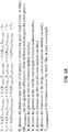
FIGs. 3A-3D illustrate a method of calculating a visible and fluorescence image, in accordance with an embodiment of the disclosure. One of ordinary skill in the art will appreciate that all portions of the method depicted may occur in a processor/controller coupled to, or included in, the endoscope. Moreover the endoscope may communicate to a local or remote processor via wireless or wired communication. In some embodiments, the processor/controller may be a distributed system (for example in embodiments where a lot of data needs to be processed, e.g., high definition video). It is appreciated that the embodiments depicted illustrate a situation where excitation light is 805 nm, and florescence light is 830 nm, but in other embodiments, other wavelengths/dyes may be used. - shows part of a method to calculate visible and fluorescence images from an endoscope. As illustrated, an image sensor generates photocharge in its pixels in response to receiving visible (red, green, and blue light), fluorescence light, and a relatively small quantity of excitation light. A processor coupled to the image sensor then separates the photocharge generated into the visible and florescence signal. This is achieved by using known parameters of the image sensor/endoscope system to solve a system of algebraic equations. For example, the various components that make up the red photocharge are known and include X1 (photons absorbed at 830 nm) multiplied by QE830 (the quantum efficiency of the image sensor at 830 nm-the fluorescence emission wavelength) and T830,notch (the transmission of 830 nm light through the notch filter). This term is then added to Y1 (visible photons absorbed) multiplied by QEvisible (the quantum efficiency of the image sensor in the visible wavelength) and Tvisible,notch (transmission of visible light through the notch filter). This term is then added to Z1 (excitation photons absorbed) multiplied by QE805 (the quantum efficiency of the image sensor in the excitation wavelength) and T805,notch (the transmission of excitation light through the notch filter). One of skill in the art will appreciate that this excitation term is ∼0 since almost no excitation light will make it through the notch filter. These terms are then added to the noise (Ni) of the image sensor. As shown, similar equations are set up for green photocharge (Pg) and blue photocharge (Pb). The depicted system of equations allow the visible (Y) and fluorescence (X) image signals to be solved for and yield the visible and fluorescence images.
-
FIG. 3B shows solving the system of equations to obtain the visible and fluorescence signals.FIG. 3B also introduces the concept of regularization in order to stabilize both the matrix and ultimately the visible and florescence images generated. In general, the mathematical operations need to solve for the visible and fluorescence images may introduce unstable conditions in certain situations (e.g., divide by zero, or other very small denominator, as a result of a readout glitch in the image sensor or the like). This may cause image distortion. Accordingly, the system may regularize the output by estimating values for X, Y, and Z. In the depicted embodiment, Γ = αI, where I is the identity matrix and α is a regularization constant. X, Y, and Z are estimated with L2 regularization such that: QL= (QTQ+ΓTΓ)-1QT, and thus X̂ = QLP. -
FIG. 3C depicts the mathematical operations to calculate the variance of the photocharge in the image sensor (variance of Pr, Pg, Pb) and consequently the variance in the visible (Y), fluorescence (X), and excitation (Z) image signals (through a similar algebraic matrix operation as discussed above in connection withFIG. 3A ). With the variance calculated, the signal to noise ratios (SNR) of X, Y, and Z can be determined. Ideally the system is attempting to maximize the SNR of the X, Y, and Z signals. -
FIG. 3D depicts a method of stabilizing the visible and fluorescence images output from the endoscope image sensor.Block 301 depicts receiving the RGB photocharge from the image sensor.Block 303 depicts initializing a value for the regularization constant (α) to stabilize the images output.Block 305 shows calculating X̂ = QLP. Block 307 depicts assuming that X̂ = X, then calculating the value of α maximizes SNRx and SNRy.Block 309 illustrates repeating the α calculation until the value of α converges. Then a final X̂ and Ŷ value are output and monitored. Finally inblock 311 the value of α is replaced. Blocks 305 - 311 repeat themselves indefinitely. -
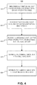
FIG. 4 illustrates amethod 400 of medical imaging, in accordance with an embodiment of the disclosure. The order in which some or all of process blocks 401 - 409 appear inmethod 400 should not be deemed limiting. Rather, one of ordinary skill in the art having the benefit of the present disclosure will understand that some ofmethod 400 may be executed in a variety of orders not illustrated, or even in parallel. -
Process block 401 shows simultaneously emitting visible light and excitation light from a distal end of a fiber optic cable of an endoscope. In one embodiment, a wavelength of the excitation light is outside a wavelength spectrum of the visible light (e.g., the excitation light has a longer wavelength than the visible light). -
Process block 403 illustrates receiving reflected visible light (including the visible light) with an image sensor. In one embodiment, a majority the excitation light is blocked from being absorbed by the image sensor with a filter. In some embodiments this may be a notch filter, or any other wavelength selective filtering. -
Process block 405 depicts receiving fluorescence light, emitted from a plurality of dye molecules, with the image sensor, and the fluorescence light is emitted in response to the plurality of dye molecules absorbing the excitation light. The fluorescence light may have a longer wavelength than the visible or excitation light. The fluorescence light is received by the image sensor contemporaneously with the reflected visible light. The reflected visible light and the fluorescence light form combined image data in the image sensor simultaneously. -
Process block 407 shows separating the combined image data into visible image data; the visible image data is commensurate to the reflected visible light received by the image sensor. -
Process block 409 illustrates separating the combined image data into fluorescence image data; the fluorescence image data is commensurate to the fluorescence light received by the image sensor. In one embodiment, separating the combined image data into visible image data and fluorescence image data includes separating the combined image data into red image data corresponding to red photocharge absorbed by the image sensor, green image data corresponding to green photocharge absorbed by the image sensor, blue image data corresponding to blue photocharge absorbed by the image sensor, and florescence image data corresponding to fluorescence photocharge absorbed by the image sensor. In some embodiments, to obtain the red green, blue, and florescence photocharge, a Bayer color filter pattern is used, but the Bayer filter does not block the florescence spectrum. - Although depicted elsewhere, in come embodiments a composite image may be formed with the visible image data and the fluorescence image data. The visible image data and the fluorescence image data may be displayed simultaneously to produce the composite image. This allows for a doctor to clearly identify different areas of the body during an operation. The composite image may include a visible image (including the visible image data) and a fluorescence image (including the fluorescence image data). The fluorescence image is overlaid on the visible image. For example if a tumor is florescent but the surrounding tissue is not, the doctor can more easily remove the tumor.
- The above description of illustrated embodiments of the invention, including what is described in the Abstract, is not intended to be exhaustive or to limit the invention to the precise forms disclosed. While specific embodiments of, and examples for, the invention are described herein for illustrative purposes, various modifications are possible within the scope of the invention, as those skilled in the relevant art will recognize.
- These modifications can be made to the invention in light of the above detailed description. The terms used in the following claims should not be construed to limit the invention to the specific embodiments disclosed in the specification. Rather, the scope of the invention is to be determined entirely by the following claims, which are to be construed in accordance with established doctrines of claim interpretation.
- The following clauses, which form part of the description, provide general expressions of the disclosure herein::
- A1. An endoscope apparatus, comprising:
- a fiber optic cable with a proximal end and a distal end opposite the proximal end;
- a light source optically coupled to the proximal end of the fiber optic cable to emit visible light and excitation light into the fiber optic cable for output from the distal end, wherein the light source is configured to emit both the visible light and the excitation light simultaneously, and wherein a wavelength of the excitation light is outside a wavelength spectrum of the visible light; and
- an image sensor coupled to the distal end of the fiber optic cable and positioned to receive a reflection of the visible light as reflected visible light.
- A2. The endoscope apparatus of clause A1, further comprising a filter disposed over the image sensor, wherein the filter blocks a majority of the excitation light from reaching the image sensor, while passing a majority of the reflected visible light to the image sensor.
- A3. The endoscope apparatus of clause A2, wherein one or more laser sources emit the visible light and the excitation light, and wherein the wavelength of the excitation light is longer than the wavelength spectrum of the visible light.
- A4. The endoscope apparatus of clause A3, wherein color filters on the image sensor are configured to pass fluorescence light contemporaneously with the reflected visible light to the image sensor, and wherein the fluorescence light has a longer wavelength than the excitation light and is generated in response to the light source emitting the excitation light.
- A5. The endoscope apparatus of clause A4, wherein the excitation light includes 805 nm light, and the fluorescence light includes 830 nm light.
- A6. The endoscope apparatus of clause A4, further comprising a processor coupled to the image sensor to receive combined image data from the image sensor, wherein the combined image data is representative of the reflected visible light and the fluorescence light, and wherein the processor includes logic that when executed by the processor causes the processor to perform operations including:
separating the combined image data into visible image data and a fluorescence image data. - A7. The endoscope apparatus of clause A6, wherein the combined image data includes a red photocharge, a green photocharge, a blue photocharge, an excitation photocharge, and a fluorescence photocharge, and wherein the processor further includes logic that when executed by the processor causes the processor to perform operations including:
- separating the combined image data into red image data corresponding to the red photocharge, green image data corresponding to the green photocharge, blue image data corresponding to the blue photocharge, and florescence image data corresponding to the fluorescence photocharge, wherein the processor employs regularized inversion to determine intensity values for the fluorescent image data and the visible image data;
- forming a composite image with the red image data, the green image data, the blue image data, and the fluorescence image data, wherein the visible image data includes the red image data, the green image data, and the blue image data.
- A8. A method of medical imaging comprising:
- simultaneously emitting visible light and excitation light from a distal end of a fiber optic cable of an endoscope, wherein a wavelength of the excitation light is outside a wavelength spectrum of the visible light;
- receiving reflected visible light including the visible light with an image sensor;
- receiving fluorescence light, emitted from a plurality of dye molecules, with the image sensor, wherein the fluorescence light is emitted in response to the plurality of dye molecules absorbing the excitation light, and wherein the fluorescence light is received by the image sensor contemporaneously with the reflected visible light, and wherein the reflected visible light and the fluorescence light form combined image data in the image sensor;
- separating the combined image data into visible image data, wherein the visible image data is commensurate to the reflected visible light received by the image sensor; and
- separating the combined image data into fluorescence image data, wherein the fluorescence image data is commensurate to the fluorescence light received by the image sensor.
- A9. The method of clause A8, further comprising blocking a majority the excitation light from being absorbed by the image sensor with a filter.
- A10. The method of clause A9, wherein separating the combined image data into visible image data and fluorescence image data includes separating the combined image data into red image data corresponding to red photocharge, green image data corresponding to green photocharge, blue image data corresponding to blue photocharge, and florescence image data corresponding to fluorescence photocharge, wherein the red image data, the green image data, and the blue image data comprise the visible image data.
- A11. The method of clause A10, further comprising forming a composite image with the visible image data and the fluorescence image data, wherein the visible image data and the fluorescence image data are displayed simultaneously to produce the composite image.
- A12. The method of clause A11, wherein the composite image includes a visible image including the visible image data and a fluorescence image including the fluorescence image data, wherein the fluorescence image is overlaid on the visible image.
- A13. The method of clause A8, wherein the wavelength of the excitation light is longer than the wavelength spectrum of the visible light, and wherein a wavelength of the fluorescence light is longer than the wavelength of the excitation light.
- A14. The method of clause A8, further comprising generating the visible light and the excitation light at a proximal end of the fiber optic cable, opposite the distal end of the fiber optic cable, with one or more laser sources, and wherein the visible light and the excitation light are emitted from the distal end.
- A15. A system for medical imaging, comprising:
- a fiber optic cable with a distal end and a proximal end opposite the distal end;
- a light source optically coupled to the proximal end of the fiber optic cable to emit visible light and excitation light into the fiber optic cable for output from the distal end;
- an image sensor coupled to the distal end of the fiber optic cable to receive reflected visible light and fluorescence light; and
- a processor disposed in the system and electrically coupled to the light source and the image sensor, wherein the processor includes logic that when executed by the processor causes the processor to perform operations including:
- instructing the light source to emit both the visible light and the excitation light simultaneously, wherein a wavelength of the excitation light is outside a wavelength spectrum of the visible light; and
- receiving combined image data from the image sensor and separating the combined image data into visible image data and fluorescence image data.
- A16. The system of clause A15, wherein the processor further includes logic that when executed by the processor causes the processor to perform operations including:
- controlling one or more laser sources in the light source to simultaneously emit the visible light and the excitation light; and
- adjusting a power supplied to the one or more laser sources to independently control an intensity of the visible light and the excitation light.
- A17. The system of clause A15, further comprising an optical filter disposed between the image sensor and the reflected visible light, wherein the optical filter is a notch filter and blocks a majority of the excitation light from being absorbed by the image sensor.
- A18. The system of clause A17, wherein separating the combined image data includes separating the combined image data into red image data corresponding to red photocharge, green image data corresponding to green photocharge, blue image data corresponding to blue photocharge, and florescence image data corresponding to fluorescence photocharge, wherein the red image data, the green image data, the blue image data comprise the visible image data.
- A19. The system of clause A18, the processor further includes logic that when executed by the processor causes the processor to perform operations including:
forming a composite image with the red image data, the green image data, the blue image data, and the fluorescence image data, wherein the composite image includes a visible image including the visible image data and a fluorescence image including the fluorescence image data, wherein the fluorescence image is contemporaneously overlaid on the visible image. - A20. The system of clause A19, wherein performing a calculation to separate the combined image data includes using a red quantum efficiency of the image sensor, a blue quantum efficiency of the image sensor, a green quantum efficiency of the image sensor, a florescence quantum efficiency of the image sensor, and a transmission of the excitation light through the notch filter.
Claims (6)
- A system for medical imaging, comprising:a fiber optic cable with a distal end and a proximal end opposite the distal end;a light source optically coupled to the proximal end of the fiber optic cable to emit visible light and excitation light into the fiber optic cable for output from the distal end;an image sensor coupled to the distal end of the fiber optic cable to receive reflected visible light and fluorescence light; anda processor disposed in the system and electrically coupled to the light source and the image sensor, wherein the processor includes logic that when executed by the processor causes the processor to perform operations including:instructing the light source to emit both the visible light and the excitation light simultaneously, wherein a wavelength of the excitation light is outside a wavelength spectrum of the visible light; andreceiving combined image data from the image sensor and separating the combined image data into visible image data and fluorescence image data.
- The system of claim 1, wherein the processor further includes logic that when executed by the processor causes the processor to perform operations including:controlling one or more laser sources in the light source to simultaneously emit the visible light and the excitation light; andadjusting a power supplied to the one or more laser sources to independently control an intensity of the visible light and the excitation light.
- The system of claim 1, further comprising an optical filter disposed between the image sensor and the reflected visible light, wherein the optical filter is a notch filter and blocks a majority of the excitation light from being absorbed by the image sensor.
- The system of claim 3, wherein separating the combined image data includes separating the combined image data into red image data corresponding to red photocharge, green image data corresponding to green photocharge, blue image data corresponding to blue photocharge, and florescence image data corresponding to fluorescence photocharge, wherein the red image data, the green image data, the blue image data comprise the visible image data.
- The system of claim 4, the processor further includes logic that when executed by the processor causes the processor to perform operations including:
forming a composite image with the red image data, the green image data, the blue image data, and the fluorescence image data, wherein the composite image includes a visible image including the visible image data and a fluorescence image including the fluorescence image data, wherein the fluorescence image is contemporaneously overlaid on the visible image. - The system of claim 5, wherein performing a calculation to separate the combined image data includes using a red quantum efficiency of the image sensor, a blue quantum efficiency of the image sensor, a green quantum efficiency of the image sensor, a florescence quantum efficiency of the image sensor, and a transmission of the excitation light through the notch filter.
Applications Claiming Priority (3)
| Application Number | Priority Date | Filing Date | Title |
|---|---|---|---|
| US15/411,221 US10386627B2 (en) | 2017-01-20 | 2017-01-20 | Simultaneous visible and fluorescence endoscopic imaging |
| PCT/US2018/012388 WO2018136238A1 (en) | 2017-01-20 | 2018-01-04 | Simultaneous visible and fluorescence endoscopic imaging |
| EP18709120.2A EP3570722B1 (en) | 2017-01-20 | 2018-01-04 | Simultaneous visible and fluorescence endoscopic imaging |
Related Parent Applications (2)
| Application Number | Title | Priority Date | Filing Date |
|---|---|---|---|
| EP18709120.2A Division-Into EP3570722B1 (en) | 2017-01-20 | 2018-01-04 | Simultaneous visible and fluorescence endoscopic imaging |
| EP18709120.2A Division EP3570722B1 (en) | 2017-01-20 | 2018-01-04 | Simultaneous visible and fluorescence endoscopic imaging |
Publications (2)
| Publication Number | Publication Date |
|---|---|
| EP3808247A1 true EP3808247A1 (en) | 2021-04-21 |
| EP3808247B1 EP3808247B1 (en) | 2023-05-03 |
Family
ID=61569345
Family Applications (2)
| Application Number | Title | Priority Date | Filing Date |
|---|---|---|---|
| EP20214764.1A Active EP3808247B1 (en) | 2017-01-20 | 2018-01-04 | Simultaneous visible and fluorescence endoscopic imaging |
| EP18709120.2A Active EP3570722B1 (en) | 2017-01-20 | 2018-01-04 | Simultaneous visible and fluorescence endoscopic imaging |
Family Applications After (1)
| Application Number | Title | Priority Date | Filing Date |
|---|---|---|---|
| EP18709120.2A Active EP3570722B1 (en) | 2017-01-20 | 2018-01-04 | Simultaneous visible and fluorescence endoscopic imaging |
Country Status (5)
| Country | Link |
|---|---|
| US (2) | US10386627B2 (en) |
| EP (2) | EP3808247B1 (en) |
| JP (1) | JP6892511B2 (en) |
| CN (1) | CN110198653B (en) |
| WO (1) | WO2018136238A1 (en) |
Families Citing this family (14)
| Publication number | Priority date | Publication date | Assignee | Title |
|---|---|---|---|---|
| US10386627B2 (en) * | 2017-01-20 | 2019-08-20 | Verily Life Sciences Llc | Simultaneous visible and fluorescence endoscopic imaging |
| US10806334B2 (en) * | 2017-02-28 | 2020-10-20 | Verily Life Sciences Llc | System and method for multiclass classification of images using a programmable light source |
| US11032481B2 (en) | 2018-07-06 | 2021-06-08 | Medos International Sarl | Camera scope electronic variable prism |
| US11202014B2 (en) | 2018-07-06 | 2021-12-14 | Medos International Sari | Camera scope electronic variable angle of view |
| US11712155B2 (en) | 2019-06-20 | 2023-08-01 | Cilag GmbH Intenational | Fluorescence videostroboscopy of vocal cords |
| CN110840386A (en) * | 2019-12-19 | 2020-02-28 | 中国科学院长春光学精密机械与物理研究所 | Visible and near-infrared fluorescence 3D co-imaging endoscopy system based on single detector |
| WO2021186803A1 (en) * | 2020-03-19 | 2021-09-23 | ソニー・オリンパスメディカルソリューションズ株式会社 | Medical observation system, control device, and control method |
| CN111568549B (en) * | 2020-05-28 | 2025-02-14 | 维景医疗科技(浙江)有限公司 | A visualization system with real-time imaging function |
| NL2026240B1 (en) * | 2020-08-07 | 2022-04-08 | Limis Dev B V | Device for coupling coherent light into an endoscopic system |
| US20230126325A1 (en) * | 2021-10-22 | 2023-04-27 | Gyrus Acmi, Inc. D/B/A Olympus Surgical Technologies America | Temporary anatomy illumination |
| CN116763239A (en) * | 2022-03-09 | 2023-09-19 | 中国科学院苏州纳米技术与纳米仿生研究所 | Broad spectrum fluorescent endoscope device |
| WO2023219807A1 (en) * | 2022-05-12 | 2023-11-16 | Verily Life Sciences Llc | Endoscope having simultaneous multi-modal imaging |
| GB202216723D0 (en) * | 2022-11-09 | 2022-12-21 | Univ Dublin | Device and method |
| US20240382167A1 (en) * | 2023-05-19 | 2024-11-21 | Nicole Daghighian | Multi-modality probe system |
Citations (2)
| Publication number | Priority date | Publication date | Assignee | Title |
|---|---|---|---|---|
| US20100286529A1 (en) * | 2009-05-08 | 2010-11-11 | Novadaq Technologies Inc. | Near infra red fluorescence imaging for visualization of blood vessels during endoscopic harvest |
| US20160062103A1 (en) * | 2014-08-29 | 2016-03-03 | Foreal Spectrum, Inc. | Endoscope system with concurrent imaging in visible and infrared wavelengths |
Family Cites Families (37)
| Publication number | Priority date | Publication date | Assignee | Title |
|---|---|---|---|---|
| JPS6338430A (en) * | 1986-08-01 | 1988-02-19 | オリンパス光学工業株式会社 | Electronic endoscope |
| US4981138A (en) * | 1988-06-30 | 1991-01-01 | Yale University | Endoscopic fiberoptic fluorescence spectrometer |
| US6293911B1 (en) * | 1996-11-20 | 2001-09-25 | Olympus Optical Co., Ltd. | Fluorescent endoscope system enabling simultaneous normal light observation and fluorescence observation in infrared spectrum |
| DE60024059T2 (en) * | 1999-01-26 | 2006-07-20 | Newton Laboratories, Inc., Woburn | DEVICE FOR AUTOFLUORESCENT IMAGING FOR AN ENDOSCOPE |
| JP3745564B2 (en) * | 1999-07-08 | 2006-02-15 | 三菱電機株式会社 | Defect inspection method and defect inspection apparatus |
| US7239782B1 (en) * | 2004-09-03 | 2007-07-03 | Chemimage Corporation | Chemical imaging fiberscope |
| JP2000081847A (en) * | 1999-09-27 | 2000-03-21 | Toshiba Corp | Image display device and light emitting device |
| JP2002051969A (en) * | 2000-08-08 | 2002-02-19 | Asahi Optical Co Ltd | Electronic endoscope device |
| US7172553B2 (en) | 2001-05-16 | 2007-02-06 | Olympus Corporation | Endoscope system using normal light and fluorescence |
| US6899675B2 (en) * | 2002-01-15 | 2005-05-31 | Xillix Technologies Corp. | Fluorescence endoscopy video systems with no moving parts in the camera |
| JP4009560B2 (en) * | 2003-06-19 | 2007-11-14 | オリンパス株式会社 | Endoscope apparatus and signal processing apparatus |
| JP4229767B2 (en) * | 2003-06-30 | 2009-02-25 | 株式会社東京精密 | Image defect inspection method, image defect inspection apparatus, and appearance inspection apparatus |
| US20050147313A1 (en) * | 2003-12-29 | 2005-07-07 | Dimitry Gorinevsky | Image deblurring with a systolic array processor |
| JP2006138708A (en) * | 2004-11-11 | 2006-06-01 | Tokyo Seimitsu Co Ltd | Image flaw inspection method, image flaw inspecting device and visual inspection device |
| JP4786910B2 (en) * | 2005-02-07 | 2011-10-05 | Hoya株式会社 | Electronic endoscope |
| JP5114024B2 (en) | 2005-08-31 | 2013-01-09 | オリンパス株式会社 | Optical imaging device |
| JP4776308B2 (en) * | 2005-09-05 | 2011-09-21 | 株式会社東京精密 | Image defect inspection apparatus, image defect inspection system, defect classification apparatus, and image defect inspection method |
| JP4954573B2 (en) * | 2006-02-28 | 2012-06-20 | オリンパス株式会社 | Endoscope system |
| US8498695B2 (en) * | 2006-12-22 | 2013-07-30 | Novadaq Technologies Inc. | Imaging system with a single color image sensor for simultaneous fluorescence and color video endoscopy |
| US7574082B2 (en) * | 2007-03-28 | 2009-08-11 | Verizon Services Organization Inc. | Optical power monitoring with robotically moved macro-bending |
| US20090244521A1 (en) * | 2008-03-31 | 2009-10-01 | General Electric Company | System and method for multi-mode optical imaging |
| JP5147538B2 (en) * | 2008-05-22 | 2013-02-20 | 富士フイルム株式会社 | Fluorescence image acquisition device and method of operating fluorescence image acquisition device |
| JP5203070B2 (en) * | 2008-07-07 | 2013-06-05 | 株式会社ジャパンディスプレイウェスト | Image input / output device, light receiving level correction method thereof, and image input method |
| JP5264382B2 (en) * | 2008-09-17 | 2013-08-14 | 富士フイルム株式会社 | Image acquisition device |
| JP5174712B2 (en) * | 2009-02-27 | 2013-04-03 | 株式会社日立ハイテクノロジーズ | Charged particle beam apparatus and position correction processing method in charged particle beam |
| KR20110032255A (en) * | 2009-09-22 | 2011-03-30 | 삼성전자주식회사 | Apparatus and method for detecting horizontal synchronization signal of image forming apparatus |
| KR101172745B1 (en) * | 2010-01-29 | 2012-08-14 | 한국전기연구원 | Combined apparatus for detection of multi-spectrum optical imaging coming out of organic body and light therapy |
| JP5481294B2 (en) * | 2010-07-15 | 2014-04-23 | 富士フイルム株式会社 | Endoscope system |
| US9345389B2 (en) | 2010-11-12 | 2016-05-24 | Emory University | Additional systems and methods for providing real-time anatomical guidance in a diagnostic or therapeutic procedure |
| JP5796244B2 (en) * | 2011-01-20 | 2015-10-21 | 株式会社山野光学 | Aperture stop for illumination |
| US9103528B2 (en) * | 2012-01-20 | 2015-08-11 | Lumencor, Inc | Solid state continuous white light source |
| CN202960439U (en) * | 2012-08-01 | 2013-06-05 | 深圳市雷迈科技有限公司 | Multi-purpose light source for medical endoscope |
| CN102914774B (en) * | 2012-09-18 | 2014-06-04 | 华中科技大学 | Synthetic aperture interferometric radiometer image inversion method |
| JP6009956B2 (en) * | 2013-01-31 | 2016-10-19 | 株式会社日立ハイテクノロジーズ | Defect inspection apparatus and defect inspection method |
| EP2967299B1 (en) | 2013-03-15 | 2022-11-30 | Stryker Corporation | Endoscopic light source and imaging system |
| JP6254907B2 (en) * | 2014-05-30 | 2017-12-27 | 株式会社モリタ製作所 | Laser light guide system |
| US10386627B2 (en) * | 2017-01-20 | 2019-08-20 | Verily Life Sciences Llc | Simultaneous visible and fluorescence endoscopic imaging |
-
2017
- 2017-01-20 US US15/411,221 patent/US10386627B2/en active Active
-
2018
- 2018-01-04 EP EP20214764.1A patent/EP3808247B1/en active Active
- 2018-01-04 WO PCT/US2018/012388 patent/WO2018136238A1/en not_active Ceased
- 2018-01-04 CN CN201880007511.2A patent/CN110198653B/en active Active
- 2018-01-04 EP EP18709120.2A patent/EP3570722B1/en active Active
- 2018-01-04 JP JP2019534283A patent/JP6892511B2/en active Active
-
2019
- 2019-04-24 US US16/393,575 patent/US10473911B2/en active Active
Patent Citations (2)
| Publication number | Priority date | Publication date | Assignee | Title |
|---|---|---|---|---|
| US20100286529A1 (en) * | 2009-05-08 | 2010-11-11 | Novadaq Technologies Inc. | Near infra red fluorescence imaging for visualization of blood vessels during endoscopic harvest |
| US20160062103A1 (en) * | 2014-08-29 | 2016-03-03 | Foreal Spectrum, Inc. | Endoscope system with concurrent imaging in visible and infrared wavelengths |
Also Published As
| Publication number | Publication date |
|---|---|
| EP3570722A1 (en) | 2019-11-27 |
| US20180210188A1 (en) | 2018-07-26 |
| EP3570722B1 (en) | 2021-03-10 |
| US20190250394A1 (en) | 2019-08-15 |
| US10473911B2 (en) | 2019-11-12 |
| WO2018136238A1 (en) | 2018-07-26 |
| CN110198653A (en) | 2019-09-03 |
| JP2020505088A (en) | 2020-02-20 |
| EP3808247B1 (en) | 2023-05-03 |
| CN110198653B (en) | 2022-05-17 |
| US10386627B2 (en) | 2019-08-20 |
| JP6892511B2 (en) | 2021-06-23 |
Similar Documents
| Publication | Publication Date | Title |
|---|---|---|
| US10473911B2 (en) | Simultaneous visible and fluorescence endoscopic imaging | |
| US12020450B2 (en) | Fluorescence imaging in a light deficient environment | |
| EP3986237B1 (en) | Pulsed illumination in a fluorescence imaging system | |
| EP2510868B1 (en) | Electronic endoscope system and method for controlling the same | |
| US20220346628A1 (en) | Micro cmos scopes for medical imaging | |
| US10694117B2 (en) | Masking approach for imaging multi-peak fluorophores by an imaging system | |
| US20130245411A1 (en) | Endoscope system, processor device thereof, and exposure control method | |
| US20140155717A1 (en) | Endoscope system, processor device, and method for operating endoscope system | |
| US20140340497A1 (en) | Processor device, endoscope system, and operation method of endoscope system | |
| JP2017094145A (en) | Image forming apparatus for tissue containing blood | |
| US20230283742A1 (en) | Imaging system having structural data enhancement for non-visible spectra | |
| CN114173633A (en) | Fluorescence imaging in low light environments | |
| US20220117474A1 (en) | Image processing apparatus, endoscope system, and operation method of image processing apparatus | |
| JP7224963B2 (en) | Medical controller and medical observation system | |
| CN116763239A (en) | Broad spectrum fluorescent endoscope device | |
| CN114786560A (en) | Endoscope device and observation method | |
| BR112020012741B1 (en) | Endoscopic system with hyperspectral imaging and tool tracking in a low-light environment. | |
| BR112020012682B1 (en) | Endoscopic system with hyperspectral imaging in a light-deficient environment. | |
| Zeng | 4 White Light Endoscopy |
Legal Events
| Date | Code | Title | Description |
|---|---|---|---|
| PUAI | Public reference made under article 153(3) epc to a published international application that has entered the european phase |
Free format text: ORIGINAL CODE: 0009012 |
|
| STAA | Information on the status of an ep patent application or granted ep patent |
Free format text: STATUS: THE APPLICATION HAS BEEN PUBLISHED |
|
| AC | Divisional application: reference to earlier application |
Ref document number: 3570722 Country of ref document: EP Kind code of ref document: P |
|
| AK | Designated contracting states |
Kind code of ref document: A1 Designated state(s): AL AT BE BG CH CY CZ DE DK EE ES FI FR GB GR HR HU IE IS IT LI LT LU LV MC MK MT NL NO PL PT RO RS SE SI SK SM TR |
|
| STAA | Information on the status of an ep patent application or granted ep patent |
Free format text: STATUS: REQUEST FOR EXAMINATION WAS MADE |
|
| 17P | Request for examination filed |
Effective date: 20211007 |
|
| RBV | Designated contracting states (corrected) |
Designated state(s): AL AT BE BG CH CY CZ DE DK EE ES FI FR GB GR HR HU IE IS IT LI LT LU LV MC MK MT NL NO PL PT RO RS SE SI SK SM TR |
|
| GRAP | Despatch of communication of intention to grant a patent |
Free format text: ORIGINAL CODE: EPIDOSNIGR1 |
|
| STAA | Information on the status of an ep patent application or granted ep patent |
Free format text: STATUS: GRANT OF PATENT IS INTENDED |
|
| INTG | Intention to grant announced |
Effective date: 20221130 |
|
| GRAS | Grant fee paid |
Free format text: ORIGINAL CODE: EPIDOSNIGR3 |
|
| GRAA | (expected) grant |
Free format text: ORIGINAL CODE: 0009210 |
|
| STAA | Information on the status of an ep patent application or granted ep patent |
Free format text: STATUS: THE PATENT HAS BEEN GRANTED |
|
| AC | Divisional application: reference to earlier application |
Ref document number: 3570722 Country of ref document: EP Kind code of ref document: P |
|
| AK | Designated contracting states |
Kind code of ref document: B1 Designated state(s): AL AT BE BG CH CY CZ DE DK EE ES FI FR GB GR HR HU IE IS IT LI LT LU LV MC MK MT NL NO PL PT RO RS SE SI SK SM TR |
|
| REG | Reference to a national code |
Ref country code: GB Ref legal event code: FG4D |
|
| REG | Reference to a national code |
Ref country code: DE Ref legal event code: R096 Ref document number: 602018049446 Country of ref document: DE |
|
| REG | Reference to a national code |
Ref country code: AT Ref legal event code: REF Ref document number: 1563900 Country of ref document: AT Kind code of ref document: T Effective date: 20230515 Ref country code: CH Ref legal event code: EP |
|
| REG | Reference to a national code |
Ref country code: IE Ref legal event code: FG4D |
|
| P01 | Opt-out of the competence of the unified patent court (upc) registered |
Effective date: 20230513 |
|
| REG | Reference to a national code |
Ref country code: LT Ref legal event code: MG9D |
|
| REG | Reference to a national code |
Ref country code: NL Ref legal event code: MP Effective date: 20230503 |
|
| REG | Reference to a national code |
Ref country code: AT Ref legal event code: MK05 Ref document number: 1563900 Country of ref document: AT Kind code of ref document: T Effective date: 20230503 |
|
| PG25 | Lapsed in a contracting state [announced via postgrant information from national office to epo] |
Ref country code: SE Free format text: LAPSE BECAUSE OF FAILURE TO SUBMIT A TRANSLATION OF THE DESCRIPTION OR TO PAY THE FEE WITHIN THE PRESCRIBED TIME-LIMIT Effective date: 20230503 Ref country code: PT Free format text: LAPSE BECAUSE OF FAILURE TO SUBMIT A TRANSLATION OF THE DESCRIPTION OR TO PAY THE FEE WITHIN THE PRESCRIBED TIME-LIMIT Effective date: 20230904 Ref country code: NO Free format text: LAPSE BECAUSE OF FAILURE TO SUBMIT A TRANSLATION OF THE DESCRIPTION OR TO PAY THE FEE WITHIN THE PRESCRIBED TIME-LIMIT Effective date: 20230803 Ref country code: NL Free format text: LAPSE BECAUSE OF FAILURE TO SUBMIT A TRANSLATION OF THE DESCRIPTION OR TO PAY THE FEE WITHIN THE PRESCRIBED TIME-LIMIT Effective date: 20230503 Ref country code: ES Free format text: LAPSE BECAUSE OF FAILURE TO SUBMIT A TRANSLATION OF THE DESCRIPTION OR TO PAY THE FEE WITHIN THE PRESCRIBED TIME-LIMIT Effective date: 20230503 Ref country code: AT Free format text: LAPSE BECAUSE OF FAILURE TO SUBMIT A TRANSLATION OF THE DESCRIPTION OR TO PAY THE FEE WITHIN THE PRESCRIBED TIME-LIMIT Effective date: 20230503 |
|
| PG25 | Lapsed in a contracting state [announced via postgrant information from national office to epo] |
Ref country code: RS Free format text: LAPSE BECAUSE OF FAILURE TO SUBMIT A TRANSLATION OF THE DESCRIPTION OR TO PAY THE FEE WITHIN THE PRESCRIBED TIME-LIMIT Effective date: 20230503 Ref country code: PL Free format text: LAPSE BECAUSE OF FAILURE TO SUBMIT A TRANSLATION OF THE DESCRIPTION OR TO PAY THE FEE WITHIN THE PRESCRIBED TIME-LIMIT Effective date: 20230503 Ref country code: LV Free format text: LAPSE BECAUSE OF FAILURE TO SUBMIT A TRANSLATION OF THE DESCRIPTION OR TO PAY THE FEE WITHIN THE PRESCRIBED TIME-LIMIT Effective date: 20230503 Ref country code: LT Free format text: LAPSE BECAUSE OF FAILURE TO SUBMIT A TRANSLATION OF THE DESCRIPTION OR TO PAY THE FEE WITHIN THE PRESCRIBED TIME-LIMIT Effective date: 20230503 Ref country code: IS Free format text: LAPSE BECAUSE OF FAILURE TO SUBMIT A TRANSLATION OF THE DESCRIPTION OR TO PAY THE FEE WITHIN THE PRESCRIBED TIME-LIMIT Effective date: 20230903 Ref country code: HR Free format text: LAPSE BECAUSE OF FAILURE TO SUBMIT A TRANSLATION OF THE DESCRIPTION OR TO PAY THE FEE WITHIN THE PRESCRIBED TIME-LIMIT Effective date: 20230503 Ref country code: GR Free format text: LAPSE BECAUSE OF FAILURE TO SUBMIT A TRANSLATION OF THE DESCRIPTION OR TO PAY THE FEE WITHIN THE PRESCRIBED TIME-LIMIT Effective date: 20230804 |
|
| PG25 | Lapsed in a contracting state [announced via postgrant information from national office to epo] |
Ref country code: FI Free format text: LAPSE BECAUSE OF FAILURE TO SUBMIT A TRANSLATION OF THE DESCRIPTION OR TO PAY THE FEE WITHIN THE PRESCRIBED TIME-LIMIT Effective date: 20230503 |
|
| PG25 | Lapsed in a contracting state [announced via postgrant information from national office to epo] |
Ref country code: SK Free format text: LAPSE BECAUSE OF FAILURE TO SUBMIT A TRANSLATION OF THE DESCRIPTION OR TO PAY THE FEE WITHIN THE PRESCRIBED TIME-LIMIT Effective date: 20230503 |
|
| PG25 | Lapsed in a contracting state [announced via postgrant information from national office to epo] |
Ref country code: SM Free format text: LAPSE BECAUSE OF FAILURE TO SUBMIT A TRANSLATION OF THE DESCRIPTION OR TO PAY THE FEE WITHIN THE PRESCRIBED TIME-LIMIT Effective date: 20230503 Ref country code: SK Free format text: LAPSE BECAUSE OF FAILURE TO SUBMIT A TRANSLATION OF THE DESCRIPTION OR TO PAY THE FEE WITHIN THE PRESCRIBED TIME-LIMIT Effective date: 20230503 Ref country code: RO Free format text: LAPSE BECAUSE OF FAILURE TO SUBMIT A TRANSLATION OF THE DESCRIPTION OR TO PAY THE FEE WITHIN THE PRESCRIBED TIME-LIMIT Effective date: 20230503 Ref country code: EE Free format text: LAPSE BECAUSE OF FAILURE TO SUBMIT A TRANSLATION OF THE DESCRIPTION OR TO PAY THE FEE WITHIN THE PRESCRIBED TIME-LIMIT Effective date: 20230503 Ref country code: DK Free format text: LAPSE BECAUSE OF FAILURE TO SUBMIT A TRANSLATION OF THE DESCRIPTION OR TO PAY THE FEE WITHIN THE PRESCRIBED TIME-LIMIT Effective date: 20230503 Ref country code: CZ Free format text: LAPSE BECAUSE OF FAILURE TO SUBMIT A TRANSLATION OF THE DESCRIPTION OR TO PAY THE FEE WITHIN THE PRESCRIBED TIME-LIMIT Effective date: 20230503 |
|
| REG | Reference to a national code |
Ref country code: DE Ref legal event code: R097 Ref document number: 602018049446 Country of ref document: DE |
|
| PLBE | No opposition filed within time limit |
Free format text: ORIGINAL CODE: 0009261 |
|
| STAA | Information on the status of an ep patent application or granted ep patent |
Free format text: STATUS: NO OPPOSITION FILED WITHIN TIME LIMIT |
|
| 26N | No opposition filed |
Effective date: 20240206 |
|
| PG25 | Lapsed in a contracting state [announced via postgrant information from national office to epo] |
Ref country code: SI Free format text: LAPSE BECAUSE OF FAILURE TO SUBMIT A TRANSLATION OF THE DESCRIPTION OR TO PAY THE FEE WITHIN THE PRESCRIBED TIME-LIMIT Effective date: 20230503 |
|
| PG25 | Lapsed in a contracting state [announced via postgrant information from national office to epo] |
Ref country code: SI Free format text: LAPSE BECAUSE OF FAILURE TO SUBMIT A TRANSLATION OF THE DESCRIPTION OR TO PAY THE FEE WITHIN THE PRESCRIBED TIME-LIMIT Effective date: 20230503 Ref country code: IT Free format text: LAPSE BECAUSE OF FAILURE TO SUBMIT A TRANSLATION OF THE DESCRIPTION OR TO PAY THE FEE WITHIN THE PRESCRIBED TIME-LIMIT Effective date: 20230503 |
|
| PG25 | Lapsed in a contracting state [announced via postgrant information from national office to epo] |
Ref country code: MC Free format text: LAPSE BECAUSE OF FAILURE TO SUBMIT A TRANSLATION OF THE DESCRIPTION OR TO PAY THE FEE WITHIN THE PRESCRIBED TIME-LIMIT Effective date: 20230503 |
|
| PG25 | Lapsed in a contracting state [announced via postgrant information from national office to epo] |
Ref country code: MC Free format text: LAPSE BECAUSE OF FAILURE TO SUBMIT A TRANSLATION OF THE DESCRIPTION OR TO PAY THE FEE WITHIN THE PRESCRIBED TIME-LIMIT Effective date: 20230503 |
|
| REG | Reference to a national code |
Ref country code: CH Ref legal event code: PL |
|
| PG25 | Lapsed in a contracting state [announced via postgrant information from national office to epo] |
Ref country code: LU Free format text: LAPSE BECAUSE OF NON-PAYMENT OF DUE FEES Effective date: 20240104 |
|
| PG25 | Lapsed in a contracting state [announced via postgrant information from national office to epo] |
Ref country code: LU Free format text: LAPSE BECAUSE OF NON-PAYMENT OF DUE FEES Effective date: 20240104 |
|
| PG25 | Lapsed in a contracting state [announced via postgrant information from national office to epo] |
Ref country code: BE Free format text: LAPSE BECAUSE OF NON-PAYMENT OF DUE FEES Effective date: 20240131 |
|
| PG25 | Lapsed in a contracting state [announced via postgrant information from national office to epo] |
Ref country code: FR Free format text: LAPSE BECAUSE OF NON-PAYMENT OF DUE FEES Effective date: 20240131 |
|
| PG25 | Lapsed in a contracting state [announced via postgrant information from national office to epo] |
Ref country code: CH Free format text: LAPSE BECAUSE OF NON-PAYMENT OF DUE FEES Effective date: 20240131 |
|
| PG25 | Lapsed in a contracting state [announced via postgrant information from national office to epo] |
Ref country code: FR Free format text: LAPSE BECAUSE OF NON-PAYMENT OF DUE FEES Effective date: 20240131 Ref country code: CH Free format text: LAPSE BECAUSE OF NON-PAYMENT OF DUE FEES Effective date: 20240131 Ref country code: BE Free format text: LAPSE BECAUSE OF NON-PAYMENT OF DUE FEES Effective date: 20240131 |
|
| REG | Reference to a national code |
Ref country code: BE Ref legal event code: MM Effective date: 20240131 |
|
| PG25 | Lapsed in a contracting state [announced via postgrant information from national office to epo] |
Ref country code: BG Free format text: LAPSE BECAUSE OF FAILURE TO SUBMIT A TRANSLATION OF THE DESCRIPTION OR TO PAY THE FEE WITHIN THE PRESCRIBED TIME-LIMIT Effective date: 20230503 |
|
| PG25 | Lapsed in a contracting state [announced via postgrant information from national office to epo] |
Ref country code: BG Free format text: LAPSE BECAUSE OF FAILURE TO SUBMIT A TRANSLATION OF THE DESCRIPTION OR TO PAY THE FEE WITHIN THE PRESCRIBED TIME-LIMIT Effective date: 20230503 |
|
| PG25 | Lapsed in a contracting state [announced via postgrant information from national office to epo] |
Ref country code: IE Free format text: LAPSE BECAUSE OF NON-PAYMENT OF DUE FEES Effective date: 20240104 |
|
| PG25 | Lapsed in a contracting state [announced via postgrant information from national office to epo] |
Ref country code: IE Free format text: LAPSE BECAUSE OF NON-PAYMENT OF DUE FEES Effective date: 20240104 |
|
| PG25 | Lapsed in a contracting state [announced via postgrant information from national office to epo] |
Ref country code: CY Free format text: LAPSE BECAUSE OF FAILURE TO SUBMIT A TRANSLATION OF THE DESCRIPTION OR TO PAY THE FEE WITHIN THE PRESCRIBED TIME-LIMIT; INVALID AB INITIO Effective date: 20180104 |
|
| PG25 | Lapsed in a contracting state [announced via postgrant information from national office to epo] |
Ref country code: HU Free format text: LAPSE BECAUSE OF FAILURE TO SUBMIT A TRANSLATION OF THE DESCRIPTION OR TO PAY THE FEE WITHIN THE PRESCRIBED TIME-LIMIT; INVALID AB INITIO Effective date: 20180104 |
|
| PG25 | Lapsed in a contracting state [announced via postgrant information from national office to epo] |
Ref country code: TR Free format text: LAPSE BECAUSE OF FAILURE TO SUBMIT A TRANSLATION OF THE DESCRIPTION OR TO PAY THE FEE WITHIN THE PRESCRIBED TIME-LIMIT Effective date: 20230503 |
|
| PGFP | Annual fee paid to national office [announced via postgrant information from national office to epo] |
Ref country code: GB Payment date: 20260126 Year of fee payment: 9 |
|
| PGFP | Annual fee paid to national office [announced via postgrant information from national office to epo] |
Ref country code: DE Payment date: 20260127 Year of fee payment: 9 |