EP3806599A1 - Determination device and component mounting apparatus having same - Google Patents
Determination device and component mounting apparatus having same Download PDFInfo
- Publication number
- EP3806599A1 EP3806599A1 EP18920366.4A EP18920366A EP3806599A1 EP 3806599 A1 EP3806599 A1 EP 3806599A1 EP 18920366 A EP18920366 A EP 18920366A EP 3806599 A1 EP3806599 A1 EP 3806599A1
- Authority
- EP
- European Patent Office
- Prior art keywords
- component
- feeder
- component feeder
- specific
- expiration date
- Prior art date
- Legal status (The legal status is an assumption and is not a legal conclusion. Google has not performed a legal analysis and makes no representation as to the accuracy of the status listed.)
- Granted
Links
Images






Classifications
-
- H—ELECTRICITY
- H05—ELECTRIC TECHNIQUES NOT OTHERWISE PROVIDED FOR
- H05K—PRINTED CIRCUITS; CASINGS OR CONSTRUCTIONAL DETAILS OF ELECTRIC APPARATUS; MANUFACTURE OF ASSEMBLAGES OF ELECTRICAL COMPONENTS
- H05K13/00—Apparatus or processes specially adapted for manufacturing or adjusting assemblages of electric components
- H05K13/04—Mounting of components, e.g. of leadless components
- H05K13/0417—Feeding with belts or tapes
-
- H—ELECTRICITY
- H05—ELECTRIC TECHNIQUES NOT OTHERWISE PROVIDED FOR
- H05K—PRINTED CIRCUITS; CASINGS OR CONSTRUCTIONAL DETAILS OF ELECTRIC APPARATUS; MANUFACTURE OF ASSEMBLAGES OF ELECTRICAL COMPONENTS
- H05K13/00—Apparatus or processes specially adapted for manufacturing or adjusting assemblages of electric components
- H05K13/08—Monitoring manufacture of assemblages
- H05K13/086—Supply management, e.g. supply of components or of substrates
-
- G—PHYSICS
- G05—CONTROLLING; REGULATING
- G05B—CONTROL OR REGULATING SYSTEMS IN GENERAL; FUNCTIONAL ELEMENTS OF SUCH SYSTEMS; MONITORING OR TESTING ARRANGEMENTS FOR SUCH SYSTEMS OR ELEMENTS
- G05B15/00—Systems controlled by a computer
- G05B15/02—Systems controlled by a computer electric
-
- G—PHYSICS
- G06—COMPUTING OR CALCULATING; COUNTING
- G06Q—INFORMATION AND COMMUNICATION TECHNOLOGY [ICT] SPECIALLY ADAPTED FOR ADMINISTRATIVE, COMMERCIAL, FINANCIAL, MANAGERIAL OR SUPERVISORY PURPOSES; SYSTEMS OR METHODS SPECIALLY ADAPTED FOR ADMINISTRATIVE, COMMERCIAL, FINANCIAL, MANAGERIAL OR SUPERVISORY PURPOSES, NOT OTHERWISE PROVIDED FOR
- G06Q10/00—Administration; Management
- G06Q10/08—Logistics, e.g. warehousing, loading or distribution; Inventory or stock management
- G06Q10/087—Inventory or stock management, e.g. order filling, procurement or balancing against orders
-
- H—ELECTRICITY
- H05—ELECTRIC TECHNIQUES NOT OTHERWISE PROVIDED FOR
- H05K—PRINTED CIRCUITS; CASINGS OR CONSTRUCTIONAL DETAILS OF ELECTRIC APPARATUS; MANUFACTURE OF ASSEMBLAGES OF ELECTRICAL COMPONENTS
- H05K13/00—Apparatus or processes specially adapted for manufacturing or adjusting assemblages of electric components
- H05K13/02—Feeding of components
-
- H—ELECTRICITY
- H05—ELECTRIC TECHNIQUES NOT OTHERWISE PROVIDED FOR
- H05K—PRINTED CIRCUITS; CASINGS OR CONSTRUCTIONAL DETAILS OF ELECTRIC APPARATUS; MANUFACTURE OF ASSEMBLAGES OF ELECTRICAL COMPONENTS
- H05K13/00—Apparatus or processes specially adapted for manufacturing or adjusting assemblages of electric components
- H05K13/08—Monitoring manufacture of assemblages
- H05K13/085—Production planning, e.g. of allocation of products to machines, of mounting sequences at machine or facility level
Definitions
- the technique disclosed in the present description relates to a determination device for determining a component feeder to be used from among multiple component feeders attached to a feeder holding section, and a component mounting apparatus having the determination device.
- Patent Literature 1 discloses an electronic component mounting device. The device determines an attachment position of the two original feeders to a position where the electronic components of each feeder can be picked up simultaneously by a mounting head. Then, the attachment position of the next feeder for accommodating the electronic component of the same type as one of the original feeders is determined to a position where the electronic component of the next feeder and the electronic component of the other original feeder can be simultaneously picked up by the mounting head.
- Patent Literature 1 JP-A-2015-149407
- the attachment position of the next feeder is determined with respect to the attachment position of the determined original feeder. In other words, it is necessary to pre-attach the original feeder and the next feeder to the determined attachment position.
- a determination device disclosed in the present description determines a component feeder to be used from among multiple component feeders attached to a feeder holding section, in a component mounting machine which includes the feeder holding section to which the multiple component feeders are attached and a mounting head capable of simultaneously picking up components from the multiple component feeders attached to the feeder holding section, and mounts the components picked up by the mounting head onto a board.
- the determination device includes: a component feeder information acquisition section configured to acquire an attachment position at which the component feeder is attached and a type of the component accommodated in the component feeder, for each component feeder attached to the feeder holding section; and a component feeder determination section configured to determine the component feeder for supplying a first specific type of component to the mounting head when component shortage occurs in a first specific component feeder, in a case where the first specific type of component supplied from the first specific component feeder and a second specific type of component supplied from a second specific component feeder are simultaneously picked up by the mounting head.
- the component feeder determination section determines one first same type component feeder, being attached to a position which enables simultaneous pickup with the second specific type of component supplied from the second specific component feeder, as the component feeder for supplying the first specific type of component to the mounting head, based on an attachment position at which the first same type component feeder is attached and an attachment position at which the second specific component feeder is attached, in a case where multiple first same type component feeders for accommodating the first specific type of component are attached to the feeder holding section.
- the component feeder attached at the attachment position at which the simultaneous pickup with the component of the second specific component feeder is possible is determined as a component feeder to be used instead of the first specific component feeder when component shortage occurs in the first specific component feeder. Accordingly, when component shortage occurs in the first specific component feeder, by using the determined component feeder and the second specific component feeder, the mounting head can continue simultaneously picking up the first specific type of component and the second specific type of component. Therefore, it is possible to mount the components efficiently.
- the component mounting machine may further include a changing device for changing an attachment position of the component feeder attached to the feeder holding section.
- the component feeder information acquisition section may further acquire a use expiration date of the component accommodated in the component feeder for each component feeder attached to the feeder holding section.
- the determination device may further include: a first detecting section configured to detect a first expiration date component feeder of which a time point is reached a first predetermined period before the use expiration date, among the first same type component feeders for accommodating the first specific type of component; and a first output section configured to output information to the changing device for prompting to change an attachment position of the first expiration date component feeder to a position which enable simultaneous pickup by the mounting head, with respect to the attachment position at which the second specific component feeder is attached.
- the component feeder information acquisition section may further acquire a use expiration date of the component accommodated in the component feeder, for each component feeder attached to the feeder holding section.
- the determination device may further include: a first detecting section configured to detect a first expiration date component feeder of which a time point is reached a first predetermined period before the use expiration date, among the first same type component feeders for accommodating the first specific type of component; and a second output section configured to output information for prompting to change an attachment position of the first expiration date component feeder to a position which enables simultaneous pickup by the mounting head, with respect to the attachment position at which the second specific component feeder is attached.
- the component feeder information acquisition section may further acquire a use expiration date of the component accommodated in the component feeder, for each component feeder attached to the feeder holding section.
- the determination device may further include: a first detecting section configured to detect a first expiration date component feeder of which a time point is reached a first predetermined period before the use expiration date, among the first same type component feeders for accommodating the first specific type of component; and a third output section configured to output information to the component mounting machine for prompting to stop simultaneous pickup of the components from the first specific component feeder and the second specific component feeder, and use the component accommodated in the first expiration date component feeder.
- the component mounting machine may further include a changing device for changing an attachment position of the component feeder attached to the feeder holding section.
- the determination device may further include: a second detecting section configured to detect a second expiration date component feeder of which a time point is reached a second predetermined period of which a period from the use expiration date is longer than that of the first predetermined period before the use expiration date among the first same type component feeders for accommodating the first specific type of component; and a fourth output section configured to output information to the changing device for prompting to change an attachment position of the second expiration date component feeder to a position which enables the simultaneous pickup by the mounting head, with respect to the attachment position at which the second specific component feeder is attached.
- the changing device changes the attachment position of the component feeder for accommodating the components (for example, components of which the use expiration date is approaching) of which a time point is reached the second predetermined period before the use expiration date, and accordingly, when component shortage occurs in the first specific component feeder, the simultaneous pickup of the components can be performed using the component feeder. Therefore, it is possible to mount the components efficiently.
- the determination device may further include: a second detecting section configured to detect a second expiration date component feeder of which a time point is reached a second predetermined period of which a period from the use expiration date is longer than that of the first predetermined period before the use expiration date, among the first same type component feeders for accommodating the first specific type of component; and a fifth output section configured to output information for prompting to change an attachment position of the second expiration date component feeder to a position which enables the simultaneous pickup by the mounting head, with respect to the attachment position at which the second specific component feeder is attached.
- the attachment position of the component feeder for accommodating the components for example, the components of which the use expiration date is approaching
- the components for example, the components of which the use expiration date is approaching
- the second predetermined period before the use expiration date is changed by the operator who recognized the information
- the component mounting machine may further include a changing device for changing an attachment position of the component feeder attached to the feeder holding section.
- the component feeder determination section may determine one first same type component feeder attached to the feeder holding section as the component feeder for supplying the first specific type of component to the mounting head, when component shortage occurs in the first specific component feeder, when the first same type component feeder attached to a position, which enables simultaneous pickup with the second specific type of component supplied from the second specific component feeder, is not present.
- the determination device may further include: a sixth output section configured to output information to the component mounting machine for prompting to subsequently pick up the second specific type of component supplied from the second specific component feeder and the first specific type of component supplied from the determined first same type component feeder; and a seventh output section configured to output information to the changing device for prompting to change an attachment position of the other one first same type component feeder for accommodating the first specific type of component to a position which enables the simultaneous pickup by the mounting head, with respect to the attachment position at which the second specific component feeder is attached.
- the simultaneous pickup of the components can be restarted, and until the component feeder that can simultaneously pick up the components can be prepared (until the attachment position is changed), by picking up the components in order, it is possible to suppress deterioration of production efficiency.
- the component feeder determination section may determine one first same type component feeder, being attached to the feeder holding section, as the component feeder for supplying the first specific type of component to the mounting head, when component shortage occurs in the first specific component feeder, when the first same type component feeder attached to a position, which enables simultaneous pickup with the second specific type of component supplied from the second specific component feeder, is not present.
- the determination device may further include: a sixth output section configured to output information to the component mounting machine for prompting to subsequently pick up the second specific type of component supplied from the second specific component feeder and the first specific type of component supplied from the determined first same type component feeder; and an eighth output section configured to output information for prompting to change an attachment position of the other one first same type component feeder for accommodating the first specific type of component to a position which enables the simultaneous pickup by the mounting head, with respect to the attachment position at which the second specific component feeder is attached.
- the attachment position of the other one first same type component feeder is changed by the operator who recognized the information, the simultaneous pickup of the components can be restarted, and until the component feeder that can simultaneously pick up the components can be prepared (until the attachment position is changed), by picking up the components in order, it is possible to suppress deterioration of production efficiency.
- the component feeder determination section may determine a combination of the first same type component feeder and the second same type component feeder which are attached in a positional relationship in which simultaneous pickup of the first specific type of component and the second specific type of component is possible, from among the first same type component feeders and the second same type component feeders, when component shortage occurs in the first specific component feeder, in a case where multiple second same type component feeders for accommodating the second specific type of component are attached to the feeder holding section, when the first same type component feeder attached to a position, which enables simultaneous pickup with the second specific type of component supplied from the second specific component feeder, is not present.
- the determination device may further include a ninth output section configured to output information to the component mounting machine for prompting to simultaneously pick up the first specific type of component and the second specific type of component which are supplied from the combination of the first same type component feeder and the second same type component feeder.
- a ninth output section configured to output information to the component mounting machine for prompting to simultaneously pick up the first specific type of component and the second specific type of component which are supplied from the combination of the first same type component feeder and the second same type component feeder.
- the determination device may further include: a production information acquisition section configured to acquire a production plan and a production speed of the component mounting machine.
- the component feeder determination section may determine to continue using the first specific component feeder even when a time point is reached a first predetermined period before the use expiration date, in a case where it is determined that it is possible to use all of the components accommodated in the first expiration date component feeder until the use expiration date of the first expiration date component feeder is reached, in a case of using the first expiration date component feeder after component shortage occurs in the first specific component feeder, based on the production plan and the production speed.
- mounting apparatus 10 is a device for mounting electronic component 4 on circuit board 2.
- Mounting apparatus 10 is also referred to as a surface mounting machine or a chip mounting apparatus. Normally, mounting apparatus 10 is provided together with other board work machines such as a solder printing machine and a board inspection machine to make up a series of mounting lines.
- mounting apparatus 10 includes multiple component feeders 12, feeder holding section 14, mounting head 16, head moving mechanism 18, board chute 22, loader 24, feeder accommodation section 26, touch panel 30, and control device 32.
- Each component feeder 12 accommodates multiple electronic components 4.
- Component feeder 12 is detachably attached to feeder holding section 14 and supplies electronic components 4 to mounting head 16.
- a specific configuration of component feeder 12 is not particularly limited, but for example, any one of a tape-type feeder which accommodates multiple electronic components 4 on a wound tape, a tray-type feeder that accommodates multiple electronic components 4 on a tray, and a bulk-type feeder that randomly accommodates multiple electronic components 4 within a container may be employed.
- Feeder holding section 14 has multiple slots, and component feeder 12 is detachably installed in each of the multiple slots.
- Feeder holding section 14 may be fixed to mounting apparatus 10 or may be detachably attached to mounting apparatus 10.
- Feeder accommodation section 26 is provided below feeder holding section 14. In feeder accommodation section 26, multiple component feeders 12 installed in feeder holding section 14 are accommodated.
- Loader 24 is a device for automatically performing the installation and removal of component feeder 12 to feeder holding section 14.
- Loader 24 is configured to remove component feeder 12 to be replaced from feeder holding section 14 and collect removed feeder accommodation section 26 to feeder accommodation section 26, and to remove component feeder 12 to be used in a production operation from feeder accommodation section 26 and install component feeder 12 in feeder holding section 14.
- Multiple mounting apparatuses 10 are arranged along the direction (X direction) perpendicular to the paper surface, and loader 24 is movable in parallel to each slot of multiple feeder holding sections 14 of multiple mounting apparatuses 10 by a guide rail (not illustrated) provided along the X direction.
- Loader 24 includes a control device (not illustrated), and the control device is configured to be capable of communicating with control device 32 (described later) of mounting apparatus 10.
- Mounting head 16 is configured to be capable of attaching and detaching nozzle 6 for picking up electronic component 4 to and from holding section 16a.
- Mounting head 16 picks up electronic component 4 supplied from component feeder 12 by nozzle 6 attached to holding section 16a, and mounts electronic component 4 on circuit board 2.
- head moving mechanism 18 moves mounting head 16 with respect to component feeder 12 and circuit board 2.
- mounting head 16 has multiple holding sections 16a, and it is possible to attach nozzle 6 to each of multiple holding sections 16a. Further, mounting head 16 can simultaneously pick up electronic component 4 from at least two component feeders 12 by nozzles 6 respectively attached to multiple holding sections 16a (for example, refer to Figs. 4 and 6 ).
- Board chute 22 conveys in, supports, and conveys out circuit board 2.
- Touch panel 30 is a display device for providing the operator with various types of information, and is a user interface for receiving a command or information from the operator.
- Control device 32 is configured with a computer including CPU, RAM, and ROM. Control device 32, for example, controls the operations of each section of mounting apparatus 10 based on the production plan. Further, control device 32 is also a determination device that determines component feeder 12 to be used by mounting device 10 from among multiple component feeders 12 attached to feeder holding section 14. Hereinafter, with reference to Fig. 3 , in order to determine component feeder 12 to be used by mounting apparatus 10, the process executed by control device 32 will be described. In the present embodiment, control device 32 has a function of the determination device that determines component feeder 12 to be used by mounting device 10, but the determination device may be a device separate from control device 32, or may be a device disposed at a position away from mounting apparatus 10.
- control device 32 determines component feeder 12 to be used by mounting apparatus 10 based on the production plan of mounting apparatus 10.
- the process of Fig. 3 is executed in a state where multiple component feeders 12 are attached to feeder holding section 14 of mounting apparatus 10 in advance.
- the process of Fig. 3 may be started with the input of the execution instruction by the operator who has confirmed the mounting of the desired number of component feeders 12 as a trigger, or may be started with the detection by control device 32 about a predetermined number of component feeders 12 are mounted, as a trigger.
- control device 32 acquires production information.
- Production information is information indicating the production plan and the production speed of each job to be produced (process for mounting electronic component 4 on circuit board 2).
- the production information may be acquired, for example, by the input of an operator to touch panel 30, or may be acquired by the reception from an external device (not illustrated).
- control device 32 acquires component feeder information.
- the component feeder information is information indicating an attachment position at which each component feeder 12 is attached, a type of electronic component 4 accommodated in each component feeder 12, and a use expiration date of electronic component 4 accommodated in each component feeder 12, for each component feeder 12 attached to feeder holding section 14.
- the use expiration date of electronic component 4 is determined, for example, at a predetermined period from the timing when stored electronic component 4 is delivered from the storage location.
- the timing at which each electronic component 4 is delivered is managed by, for example, an identification number assigned to each electronic component 4.
- the use expiration date of each electronic component 4 may be input to touch panel 30 by an operator, for example.
- control device 32 determines an original feeder based on the production information.
- the original feeder is component feeder 12 for supplying electronic component 4 to mounting head 16 prior to the next feeder (described later).
- the next feeder is component feeder 12 for supplying electronic components 4 to mounting head 16 instead of the original feeder in a case where component shortage occurs in the original feeder.
- the supply number of multiple electronic components 4 mounted on one circuit board 2 is not sufficient only with the original feeder, and thus the next feeder is prepared.
- control device 32 selects two component feeders 12 attached in the positional relationship in which the simultaneous pickup of component X and component Y is possible from among the multiple component feeders 12 for accommodating multiple component feeders 12 for accommodating components X and multiple component feeders 12 for accommodating components Y. Specifically, as illustrated in Fig. 4 , control device 32 determines first component feeder 12a for accommodating component X, and second component feeder 12b for accommodating component Y, as an original feeder.
- control device 32 outputs an instruction to start the production operation to each section (mounting head 16, head moving mechanism 18, board chute 22, and the like) using the original feeder determined in S14. Accordingly, mounting head 16 starts to simultaneously pick up components X and Y from first component feeder 12a and second component feeder 12b, and the production operation is executed according to the acquired production plan.
- component feeder 12 to be used is determined from the two original feeders in a case where component shortage occurs in first component feeder 12a.
- control device 32 extracts first same type component feeder 12A (refer to Fig. 5 ) from among multiple component feeders 12 attached to feeder holding section 14.
- First same type component feeder 12A is component feeder 12 for accommodating the same type of component (that is, component X) as the component accommodated in first component feeder 12a.
- control device 32 determines whether first expiration date component feeder 12c (refer to Fig. 5 ) is present.
- First expiration date component feeder 12c is component feeder 12 in which a time point is reached a first predetermined period (for example, three hours) before the use expiration date among first same type component feeders 12A.
- a first predetermined period for example, three hours
- control device 32 outputs an instruction to loader 24 to change the attachment position of first expiration date component feeder 12c to a position which enables the simultaneous pickup by mounting head 16, with respect to the attachment position at which second component feeder 12b is attached.
- control device 32 outputs an instruction to loader 24 to replace the attachment position of first expiration date component feeder 12c and the attachment position (that is, a position at which the simultaneous pickup by mounting head 16 is possible with respect to the attachment position at which second component feeder 12b is attached) of component feeder 12t for accommodating the components (component Z in Fig. 5 ) different from component X.
- loader 24 executes an operation of replacing the attachment position of first expiration date component feeder 12c and the attachment position of component feeder 12t.
- control device 32 determines whether the change of the attachment position according to the instruction output to loader 24 in S22 has been completed. In a case where it is determined that the change of the attachment position has been completed (YES in S24), the process proceeds to S26, and in a case where it is determined that the change of the attachment position has not been completed (NO in S24), S24 is repeated until YES is determined in S24.
- control device 32 updates component feeder information. As described above, in S24, since the attachment position of first expiration date component feeder 12c and component feeder 12t has been changed, control device 32 updates the attachment position at which each component feeder 12 is attached, and the type of electronic component 4 accommodated in each component feeder 12, for each component feeder 12 attached to feeder holding section 14, to the latest information (refer to Fig. 6 ).
- control device 32 determines whether all of components X accommodated in first expiration date component feeder 12c can be used until the use expiration date is reached. During the production operation, control device 32 grasps the remaining number of components X accommodated in the original feeder (that is, first component feeder 12a).
- control device 32 determines whether all of components X accommodated in first expiration date component feeder 12c can be used until the use expiration date is reached.
- control device 32 outputs an instruction to use first expiration date component feeder 12c.
- first expiration date component feeder 12c after component shortage occurs in first component feeder 12a, since it is determined that it is not possible to use up components X accommodated in first expiration date component feeder 12c until the use expiration date is reached, control device 32 determines to use first expiration date component feeder 12c with priority instead of first component feeder 12a.
- control device 32 determines the next feeder. Specifically, in a case of NO in S20, for example, as illustrated in Fig. 7 , based on the attachment position at which each first same type component feeder 12A is attached and the attachment position at which second component feeder 12b is attached, control device 32 determines first same type component feeder 12A attached to the position at which the simultaneous pickup with components Y supplied from second component feeder 12b is possible as next feeder 12e. In a case of YES in S28, control device 32 determines first expiration date component feeder 12c of which the attachment position has been changed as the next feeder.
- a case of YES in S28 is a case where all of components X accommodated in first expiration date component feeder 12c can be used until the use expiration date is reached when first expiration date component feeder 12c is used after component shortage occurs in first component feeder 12a, and thus control device 32 continues using first component feeder 12a and determines first expiration date component feeder 12c as the next feeder. Further, in a case of passing through S30, first expiration date component feeder 12c is used instead of first component feeder 12a, control device 32 determines first component feeder 12a as the next feeder.
- mounting head 16 can simultaneously pick up components X and Y from second component feeder 12b and the next feeder.
- control device 32 ends the series of processes.
- control device 32 of the present embodiment determines component feeder 12 attached to the attachment position at which the simultaneous pickup with component Y of second component feeder 12b is possible as next feeder 12e to be used instead of first component feeder 12a when component shortage occurs in first component feeder 12a, among multiple first same type component feeders 12A for accommodating components X (No in S20, S32). Accordingly, when component shortage occurs in first component feeder 12a, by using next feeder 12e and second component feeder 12b, mounting head 16 can continue the simultaneous pickup of components X and Y. Therefore, it is possible to mount the components efficiently.
- control device 32 In a case where first expiration date component feeder 12c (that is, component feeder 12 for accommodating the components of which the use expiration date is approaching) is present among first same type component feeders 12A (YES in S20), control device 32 outputs information to loader 24 for prompting to change the attachment position of first expiration date component feeder 12c to the position at which the simultaneous pickup with components Y supplied from second component feeder 12b is possible (S22). Therefore, by changing the attachment position of first expiration date component feeder 12c by loader 24, it is possible to use (simultaneously pick up) components X of which the use expiration date is approaching, with priority. Therefore, it is possible to suppress the use expiration of components X.
- control device 32 continues using first component feeder 12a even when a time point is reached the first predetermined period before the use expiration date and determines first expiration date component feeder 12c as the next feeder (S32). Therefore, it is possible to reduce the number of times of switching of component feeder 12 to be used, and it is possible to suppress deterioration of mounting efficiency of components.
- a mounting apparatus according to a second embodiment will be described.
- the configuration of the mounting apparatus is the same as that in the first embodiment, but the process of control device 32 according to the presence or absence of first expiration date component feeder 12c is different.
- control device 32 of the second embodiment determines component feeder 12 to be used by the mounting apparatus will be described.
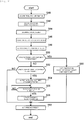
- S40 to S50 are respectively the same as S10 to S20 in Fig. 3 .
- control device 32 determines whether second expiration date component feeder 12d is present.
- Second expiration date component feeder 12d is component feeder 12 of which a time point is reached a second predetermined period (for example, 4 hours) of which a period from the use expiration date is longer than that of the first predetermined period before the use expiration date among first same type component feeders 12A.
- the process proceeds to S54, and when it is determined that second expiration date component feeder 12d is not present (NO in S52), the process proceeds to S62.
- control device 32 outputs an instruction to loader 24 to change the attachment position of second expiration date component feeder 12b to the position (attachment position of component feeder 12t) at which the simultaneous pickup by mounting head 16 is possible, with respect to the attachment position at which second component feeder 12d is attached.
- S56 to S58 are the same as S26 and S28 in Fig. 3 .
- control device 32 outputs an instruction to each section to stop the simultaneous pickup of components X and Y from first component feeder 12a and second component feeder 12b, and execute the production operation using first expiration date component feeder 12c. More specifically, control device 32 outputs an instruction to subsequently pick up components X supplied from first expiration date component feeder 12c and components Y supplied from second component feeder 12b, and mount the picked-up components on circuit board 2.
- control device 32 determines the next feeder. Specifically, in a case of NO in S52, based on the attachment position at which each first same type component feeder 12A is attached and the attachment position at which second component feeder 12b is attached, control device 32 determines first same type component feeder 12A attached to the position at which the simultaneous pickup with components Y supplied from second component feeder 12b is possible, as next feeder 12e (refer to Fig. 7 ). In a case of YES in S52, control device 32 determines second expiration date component feeder 12d of which the attachment position has been changed as the next feeder. In a case of YES in S50, control device 32 determines first component feeder 12a of which the simultaneous pickup is stopped, as the next feeder. When executing S62, control device 32 ends the series of processes.
- control device 32 of the present embodiment uses components X of first expiration date component feeder 12c of which the use expiration date is approaching, prior to the simultaneous pickup of components X and Y from first component feeder 12a and second component feeder 12b, and thus it is possible to suppress the use expiration of the components.
- second expiration date component feeder 12d that is, the component feeder for accommodating the components of which the use expiration date is approaching
- information is output to loader 24 for prompting to change the attachment position of second expiration date component feeder 12d to a position which enables the simultaneous pickup with components Y supplied from second component feeder 12b (S54).
- second expiration date component feeder 12d is determined as the next feeder. In this manner, by changing the attachment position of second expiration date component feeder 12d in advance before the use expiration date of the components approaches, when component shortage occurs in first component feeder 12a, it is possible to use second expiration date component feeder 12d and continue the simultaneous pickup of components to be used. Therefore, it is possible to mount the components efficiently.
- next feeder is determined when the component shortage occurs in the original feeder.
- control device 32 of a third embodiment determines component feeder 12 to be used by the mounting apparatus will be described.
- S70 to S76 are the same as S10 to S16 in Fig. 3 .
- control device 32 determines whether the component shortage occurs in the original feeder (that is, first component feeder 12a). In a case where it is determined that component shortage occurs in first component feeder 12a (YES in S78), the process proceeds to S80, and in a case where it is determined that component shortage occurs in first component feeder 12a (NO in S78), S78 is repeated.
- control device 32 determines whether first same type component feeder 12A attached to a position at which the simultaneous pickup with components Y supplied from second component feeder 12b is possible is present. In a case where it is determined that first same type component feeder 12A attached to a position at which the simultaneous pickup with components Y of second component feeder 12b is possible is present (YES in S80) the process proceeds to S92, and in a case where it is determined that first same type component feeder 12A attached to a position at which the simultaneous pickup with components Y of second component feeder 12b is possible is not present (NO in S80), the process proceeds to S82.
- control device 32 determines one of first same type component feeders 12A as component feeder 12f for supplying components X to mounting head 16. In a case where multiple first same type component feeders 12A are present, any one of first same type component feeders 12A may be determined.
- control device 32 outputs an instruction to each section to subsequently pick up components Y supplied from second component feeder 12b, and components X supplied from the one component feeder 12f determined in S82, by mounting head 16.
- a case of subsequently picking up components X and Y means, for example, a case of picking up component X of component feeder 12f by another nozzle 6 in a state where component Y is picked up by one nozzle 6 after component Y of second component feeder 12b is picked up.
- control device 32 selects one component feeder 12g different from first same type component feeder 12A (component feeder 12f) determined in S82. In a case where multiple first same type component feeders 12A to be selected are present, any one of first same type component feeders 12A to be selected may be determined.
- control device 32 outputs an instruction to loader 24 to change the attachment position of component feeder 12g selected in S86 to a position which enables the simultaneous pickup by mounting head 16, with respect to the attachment position which second component feeder 12b is attached.
- S90 to S92 are the same as S26 and S28 in Fig. 3 .
- mounting head 16 executes the subsequent pickup of components X and Y from second component feeder 12b and one component feeder 12f determined in S82.
- control device 32 determines first same type component feeder 12A (that is, component feeder 12g selected in S88) of which the attachment position is changed in S90, as next feeder 12e. Then, in S96, control device 32 outputs an instruction to each section to simultaneously pick up components X supplied from determined next feeder 12e and components Y supplied from second component feeder 12b, by mounting head 16. When executing S96, control device 32 ends the series of processes.
- control device 32 of the present embodiment When component shortage occurs in first component feeder 12a, in a case where first same type component feeder 12A of which the simultaneous pickup is possible is not present (NO in S80), control device 32 of the present embodiment outputs an instruction to each section to use one first same type component feeder 12A and second component feeder 12b, and subsequently pick up components X and Y (S84). Then, while picking up components X and Y in order, information is output to loader 24 for prompting to change the attachment position of another one first same type component feeder 12A to a position at which the simultaneous pickup with components Y supplied from second component feeder 12b is possible (S86). Then, another one first same type component feeder 12A is determined as the next feeder (S94).
- a mounting apparatus in a case where first same type component feeder 12A in which the simultaneous pickup is possible is not present when component shortage occurs in one original feeder, another original feeder (in which components are remaining) is also changed together.
- control device 32 of the fourth embodiment the process of determining component feeder 12 to be used by the mounting apparatus will be described.
- control device 32 determines the combination in which the simultaneous pickup of components X and Y is possible, from multiple component feeders 12 attached to feeder holding section 14. Specifically, first, control device 32 extracts first same type component feeder 12A and second same type component feeder 12B from among multiple component feeders 12 attached to feeder holding section 14. Second same type component feeder 12B is component feeder 12 for accommodating the same type of component (that is, component Y) as the component accommodated in second component feeder 12b. Then, as illustrated in Fig.
- control device 32 determines combination 12C of first same type component feeder 12A and second same type component feeder 12B which are attached in a positional relationship in which the simultaneous pickup of components X and components Y is possible.
- control device 32 determines the next feeder in S114.
- S114 is the same as S94 in FIG. 10 .
- control device 32 outputs an instruction to each section to simultaneously pick up component X and component Y by mounting head 16. Specifically, in a case of NO in S110, control device 32 instructs the simultaneous pickup of components X and components Y supplied from combination 12C determined in S112. In a case of YES in S110, it is instructed to simultaneously pick up components X and components Y supplied from next feeder 12e and second component feeder 12b determined in S114. When executing S116, control device 32 ends the series of processes.
- control device 32 of the present embodiment When component shortage occurs in first component feeder 12a, in a case where first same type component feeder 12A in which the simultaneous pickup with components Y of second component feeder 12b is possible is not present (NO in S110), control device 32 of the present embodiment outputs information for prompting to determine the combination of first same type component feeder 12A and second same type component feeder 12B in a positional relationship in which the simultaneous pickup of components X and components Y is possible (S112), and perform the simultaneous pickup of components X and components Y supplied from the combination (S116). Therefore, even in a case where first same type component feeder 12A in which the simultaneous pickup with component Y supplied from second component feeder 12b is not present, it is possible to continue the simultaneous pickup of components X and Y, and it is possible to maintain the mounting efficiency of components.
- First component feeder 12a and second component feeder 12b are examples of the "first specific component feeder” and the “second specific component feeder”, respectively.
- Component X and component Y are examples of the "first specific type of component” and the “second specific type of component”, respectively.
- Loader 24 is an example of the "changing device”.
- S12, S42, S72, and S102 are examples of the process executed by the "component feeder information acquisition section”.
- S32, S62, S94, S112, and S114 are examples of the process executed by the "component feeder determination section”.
- S22 is an example of the process executed by the "first output section”.
- S20 and S50 are examples of the process executed by the "first detecting section”.
- S60 is an example of the process executed by the "third output section”.
- S52 is an example of the process executed by the "second detecting section”.
- S54 is an example of the process executed by the "fourth output section”.
- S84 is an example of the process executed by the "sixth output section”.
- S88 is an example of the process executed by the "seventh output section”.
- S116 is an example of the process executed by the "ninth output section”.
- two adjacent component feeders 12 are described as a positional relationship in which the simultaneous pickup is possible, but the positional relationship in which the simultaneous pickup is possible may be appropriately changed by the arrangement of holding sections 16a of mounting head 16, the type of nozzle 6, and the like.
- control device 32 need not acquire the production information, need not determine whether first expiration date component feeder 12c is present, or need not output an instruction to change the attachment position of first expiration date component feeder 12c.
- S10, S20, and S22 in Fig. 3 may be omitted.
- the "production information acquisition section”, “first detecting section”, and “first output section” can be omitted.
- S14, S16, and S24 to S30 need not be executed.
- control device 32 may execute at least the processes of S12, S18, and S32. In S12, the use expiration date of electronic component 4 accommodated in each component feeder 12 need not be acquired.
- control device 32 outputs an instruction to loader 24 to change the attachment position of first expiration date component feeder 12c or the like (S22, S52, and S88), but instead of this, information for prompting to change the attachment position of first expiration date component feeder 12c or the like may be displayed on touch panel 30.
- the processes of S22, S52, and S88 are examples of the process executed by the "second output section", the "fifth output section", and the "eighth output section", respectively.
Landscapes
- Engineering & Computer Science (AREA)
- Manufacturing & Machinery (AREA)
- Microelectronics & Electronic Packaging (AREA)
- Business, Economics & Management (AREA)
- Operations Research (AREA)
- Economics (AREA)
- General Physics & Mathematics (AREA)
- Physics & Mathematics (AREA)
- Accounting & Taxation (AREA)
- Development Economics (AREA)
- Human Resources & Organizations (AREA)
- Marketing (AREA)
- Quality & Reliability (AREA)
- Strategic Management (AREA)
- Tourism & Hospitality (AREA)
- Entrepreneurship & Innovation (AREA)
- General Business, Economics & Management (AREA)
- Finance (AREA)
- Theoretical Computer Science (AREA)
- General Engineering & Computer Science (AREA)
- Automation & Control Theory (AREA)
- Supply And Installment Of Electrical Components (AREA)
Abstract
Description
- The technique disclosed in the present description relates to a determination device for determining a component feeder to be used from among multiple component feeders attached to a feeder holding section, and a component mounting apparatus having the determination device.
- Patent Literature 1 discloses an electronic component mounting device. The device determines an attachment position of the two original feeders to a position where the electronic components of each feeder can be picked up simultaneously by a mounting head. Then, the attachment position of the next feeder for accommodating the electronic component of the same type as one of the original feeders is determined to a position where the electronic component of the next feeder and the electronic component of the other original feeder can be simultaneously picked up by the mounting head.
- Patent Literature 1:
JP-A-2015-149407 - In the technique of Patent Literature 1, the attachment position of the next feeder is determined with respect to the attachment position of the determined original feeder. In other words, it is necessary to pre-attach the original feeder and the next feeder to the determined attachment position. In the present description, there is provide a technique capable of mounting components efficiently in a state where multiple component feeders are attached in advance.
- A determination device disclosed in the present description determines a component feeder to be used from among multiple component feeders attached to a feeder holding section, in a component mounting machine which includes the feeder holding section to which the multiple component feeders are attached and a mounting head capable of simultaneously picking up components from the multiple component feeders attached to the feeder holding section, and mounts the components picked up by the mounting head onto a board. The determination device includes: a component feeder information acquisition section configured to acquire an attachment position at which the component feeder is attached and a type of the component accommodated in the component feeder, for each component feeder attached to the feeder holding section; and a component feeder determination section configured to determine the component feeder for supplying a first specific type of component to the mounting head when component shortage occurs in a first specific component feeder, in a case where the first specific type of component supplied from the first specific component feeder and a second specific type of component supplied from a second specific component feeder are simultaneously picked up by the mounting head. The component feeder determination section determines one first same type component feeder, being attached to a position which enables simultaneous pickup with the second specific type of component supplied from the second specific component feeder, as the component feeder for supplying the first specific type of component to the mounting head, based on an attachment position at which the first same type component feeder is attached and an attachment position at which the second specific component feeder is attached, in a case where multiple first same type component feeders for accommodating the first specific type of component are attached to the feeder holding section.
- In the above-described determination device, from among the multiple first same type component feeders for accommodating the first specific type of component, the component feeder attached at the attachment position at which the simultaneous pickup with the component of the second specific component feeder is possible is determined as a component feeder to be used instead of the first specific component feeder when component shortage occurs in the first specific component feeder. Accordingly, when component shortage occurs in the first specific component feeder, by using the determined component feeder and the second specific component feeder, the mounting head can continue simultaneously picking up the first specific type of component and the second specific type of component. Therefore, it is possible to mount the components efficiently.
-
-
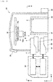
Fig. 1 is a side view schematically illustrating a configuration of a component mounting apparatus of an embodiment. -
Fig. 2 is a sectional view taken along line II-II ofFig. 1 . -
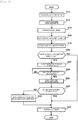
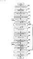
Fig. 3 is a flowchart illustrating a process executed by a control device (determination device) of a first embodiment. -
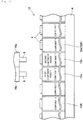
Fig. 4 is a view illustrating an example of an original feeder determined by the process ofFig. 3 . -
Fig. 5 is a view illustrating a state of changing an attachment position of a first expiration date component feeder. -
Fig. 6 is a view illustrating a state where the attachment position of the first expiration date component feeder has been changed. -
Fig. 7 is a view illustrating an example of a next feeder determined by the process ofFig. 3 . -
Fig. 8 is a flowchart illustrating a process executed by a control device (determination device) of a second embodiment. -
Fig. 9 is a view illustrating a state of changing an attachment position of a second expiration date component feeder. -
Fig. 10 is a flowchart illustrating a process executed by a control device (determination device) of a third embodiment. -
Fig. 11 is a view illustrating a state of changing an attachment position of the other one first same type component feeder and a state of executing subsequent pickup. -
Fig. 12 is a view illustrating an example of a next feeder determined by the process ofFig. 10 . -
Fig. 13 is a flowchart illustrating a process executed by a control device (determination device) of a fourth embodiment. -
Fig. 14 is a view illustrating an example of a combination of component feeders determined by the process ofFig. 13 . - In one embodiment disclosed in the present description, the component mounting machine may further include a changing device for changing an attachment position of the component feeder attached to the feeder holding section. The component feeder information acquisition section may further acquire a use expiration date of the component accommodated in the component feeder for each component feeder attached to the feeder holding section. The determination device may further include: a first detecting section configured to detect a first expiration date component feeder of which a time point is reached a first predetermined period before the use expiration date, among the first same type component feeders for accommodating the first specific type of component; and a first output section configured to output information to the changing device for prompting to change an attachment position of the first expiration date component feeder to a position which enable simultaneous pickup by the mounting head, with respect to the attachment position at which the second specific component feeder is attached. In such a configuration, among the components accommodated in the component feeder attached to the feeder holding section, in a case where the component feeder for accommodating the components (for example, components of which the use expiration date is approaching) of which a time point is reached the first predetermined period before the use expiration date is present, information is output to the changing device for prompting to change the attachment position of the component feeder to the position which enables the simultaneous pickup with the component supplied from the second specific component feeder. Therefore, by changing the attachment position of the component feeder by the changing device, it is possible to simultaneously pick up the components of which the use expiration date is approaching by the mounting head, and the component can be used with priority. Therefore, it is possible to suppress the use expiration of the component.
- In one embodiment disclosed in the present description, the component feeder information acquisition section may further acquire a use expiration date of the component accommodated in the component feeder, for each component feeder attached to the feeder holding section. The determination device may further include: a first detecting section configured to detect a first expiration date component feeder of which a time point is reached a first predetermined period before the use expiration date, among the first same type component feeders for accommodating the first specific type of component; and a second output section configured to output information for prompting to change an attachment position of the first expiration date component feeder to a position which enables simultaneous pickup by the mounting head, with respect to the attachment position at which the second specific component feeder is attached. In such a configuration, among the components accommodated in the component feeder attached to the feeder holding section, in a case where the component feeder for accommodating the components (for example, component of which the use expiration date is approaching) of which a time point is reached the first predetermined period before the use expiration date is present, information is output for prompting to change the attachment position of the component feeder to the position which enables the simultaneous pickup with the component supplied from the second specific component feeder. Therefore, for example, the attachment position of the component feeder is changed by an operator who recognizes the information, and accordingly, it is possible to simultaneously pick up the components of which the use expiration date is approaching by the mounting head, and the component can be used with priority. Therefore, it is possible to suppress the use expiration of the component.
- In one embodiment disclosed in the present description, the component feeder information acquisition section may further acquire a use expiration date of the component accommodated in the component feeder, for each component feeder attached to the feeder holding section. The determination device may further include: a first detecting section configured to detect a first expiration date component feeder of which a time point is reached a first predetermined period before the use expiration date, among the first same type component feeders for accommodating the first specific type of component; and a third output section configured to output information to the component mounting machine for prompting to stop simultaneous pickup of the components from the first specific component feeder and the second specific component feeder, and use the component accommodated in the first expiration date component feeder. In such a configuration, among the components accommodated in the component feeder attached to the feeder holding section, in a case where the component feeder for accommodating the components (for example, the components of which the use expiration date is approaching) of which a time point is reached the first predetermined period before the use expiration date is present, in order to use the components of which the use expiration date is approaching prior to the simultaneous pickup during execution, the use expiration of the component is suppressed.
- In one embodiment disclosed in the present description, the component mounting machine may further include a changing device for changing an attachment position of the component feeder attached to the feeder holding section. The determination device may further include: a second detecting section configured to detect a second expiration date component feeder of which a time point is reached a second predetermined period of which a period from the use expiration date is longer than that of the first predetermined period before the use expiration date among the first same type component feeders for accommodating the first specific type of component; and a fourth output section configured to output information to the changing device for prompting to change an attachment position of the second expiration date component feeder to a position which enables the simultaneous pickup by the mounting head, with respect to the attachment position at which the second specific component feeder is attached. In such a configuration, the changing device changes the attachment position of the component feeder for accommodating the components (for example, components of which the use expiration date is approaching) of which a time point is reached the second predetermined period before the use expiration date, and accordingly, when component shortage occurs in the first specific component feeder, the simultaneous pickup of the components can be performed using the component feeder. Therefore, it is possible to mount the components efficiently.
- In one embodiment disclosed in the present description, the determination device may further include: a second detecting section configured to detect a second expiration date component feeder of which a time point is reached a second predetermined period of which a period from the use expiration date is longer than that of the first predetermined period before the use expiration date, among the first same type component feeders for accommodating the first specific type of component; and a fifth output section configured to output information for prompting to change an attachment position of the second expiration date component feeder to a position which enables the simultaneous pickup by the mounting head, with respect to the attachment position at which the second specific component feeder is attached. In such a configuration, the attachment position of the component feeder for accommodating the components (for example, the components of which the use expiration date is approaching) of which a time point is reached the second predetermined period before the use expiration date is changed by the operator who recognized the information, and accordingly, when component shortage occurs in the first specific component feeder, the simultaneous pickup of the components can be performed using the component feeder. Therefore, it is possible to mount the components efficiently.
- In one embodiment disclosed in the present description, the component mounting machine may further include a changing device for changing an attachment position of the component feeder attached to the feeder holding section. The component feeder determination section may determine one first same type component feeder attached to the feeder holding section as the component feeder for supplying the first specific type of component to the mounting head, when component shortage occurs in the first specific component feeder, when the first same type component feeder attached to a position, which enables simultaneous pickup with the second specific type of component supplied from the second specific component feeder, is not present. The determination device may further include: a sixth output section configured to output information to the component mounting machine for prompting to subsequently pick up the second specific type of component supplied from the second specific component feeder and the first specific type of component supplied from the determined first same type component feeder; and a seventh output section configured to output information to the changing device for prompting to change an attachment position of the other one first same type component feeder for accommodating the first specific type of component to a position which enables the simultaneous pickup by the mounting head, with respect to the attachment position at which the second specific component feeder is attached. In such a configuration, when component shortage occurs in the first specific component feeder, in a case where the first same type component feeder is not present in the attachment position at which the simultaneous pickup is possible, by using the one first same type component feeder and the second specific component feeder, the instruction to pick up the components in order is output to the component mounting machine. Then, while picking up the components in order, the information is output to the changing device for prompting to change the other one first same type component feeder to the attachment position at which the simultaneous pickup with the components supplied from the second specific component feeder is possible. Therefore, by changing the attachment position of the other one first same type component feeder by the changing device, the simultaneous pickup of the components can be restarted, and until the component feeder that can simultaneously pick up the components can be prepared (until the attachment position is changed), by picking up the components in order, it is possible to suppress deterioration of production efficiency.
- In one embodiment disclosed in the present description, the component feeder determination section may determine one first same type component feeder, being attached to the feeder holding section, as the component feeder for supplying the first specific type of component to the mounting head, when component shortage occurs in the first specific component feeder, when the first same type component feeder attached to a position, which enables simultaneous pickup with the second specific type of component supplied from the second specific component feeder, is not present. The determination device may further include: a sixth output section configured to output information to the component mounting machine for prompting to subsequently pick up the second specific type of component supplied from the second specific component feeder and the first specific type of component supplied from the determined first same type component feeder; and an eighth output section configured to output information for prompting to change an attachment position of the other one first same type component feeder for accommodating the first specific type of component to a position which enables the simultaneous pickup by the mounting head, with respect to the attachment position at which the second specific component feeder is attached. In such a configuration, when component shortage occurs in the first specific component feeder, in a case where the first same type component feeder is not present in the attachment position at which the simultaneous pickup is possible, by using the one first same type component feeder and the second specific component feeder, the instruction to pick up the components in order is output to the component mounting machine. Then, while picking up the components in order, information is output for prompting to change the other one first same type component feeder to the attachment position at which the simultaneous pickup with the component supplied from the second specific component feeder is possible. Therefore, for example, the attachment position of the other one first same type component feeder is changed by the operator who recognized the information, the simultaneous pickup of the components can be restarted, and until the component feeder that can simultaneously pick up the components can be prepared (until the attachment position is changed), by picking up the components in order, it is possible to suppress deterioration of production efficiency.
- In one embodiment disclosed in the present description, the component feeder determination section may determine a combination of the first same type component feeder and the second same type component feeder which are attached in a positional relationship in which simultaneous pickup of the first specific type of component and the second specific type of component is possible, from among the first same type component feeders and the second same type component feeders, when component shortage occurs in the first specific component feeder, in a case where multiple second same type component feeders for accommodating the second specific type of component are attached to the feeder holding section, when the first same type component feeder attached to a position, which enables simultaneous pickup with the second specific type of component supplied from the second specific component feeder, is not present. The determination device may further include a ninth output section configured to output information to the component mounting machine for prompting to simultaneously pick up the first specific type of component and the second specific type of component which are supplied from the combination of the first same type component feeder and the second same type component feeder. In such a configuration, when the component shortage occurs in the first specific component feeder, in a case where the first same type component feeder is not present at the attachment position at which the simultaneous pickup with the components supplied from the second specific component feeder is possible, the combination of the first same type component feeder and the second same type component feeder in the positional relationship in which the simultaneous pickup of the components is possible is determined, and the information is output to the component mounting machine for prompting to perform the simultaneous pickup of the components supplied from the combination. Therefore, when the component shortage occurs in the first specific component feeder, even in a case where the first same type component feeder capable of simultaneously picking up the components of the second specific component feeder, it is possible to continue simultaneously picking up the components, and to maintain the mounting efficiency of the components.
- In one embodiment disclosed in the present specification, the determination device may further include: a production information acquisition section configured to acquire a production plan and a production speed of the component mounting machine. The component feeder determination section may determine to continue using the first specific component feeder even when a time point is reached a first predetermined period before the use expiration date, in a case where it is determined that it is possible to use all of the components accommodated in the first expiration date component feeder until the use expiration date of the first expiration date component feeder is reached, in a case of using the first expiration date component feeder after component shortage occurs in the first specific component feeder, based on the production plan and the production speed. In such a configuration, in a case where it is determined that all of the components accommodated in the first expiration date component feeder after the component shortage of the first specific component feeder currently in use occurs can be used until the use expiration date is reached, the use of the first specific component feeder is continued, and thus, it is possible to reduce the number of times of switching of the component feeder to be used. Therefore, it is possible to suppress deterioration of mounting efficiency of the components.
- Hereinafter, with reference to the drawings, component mounting apparatus 10 (hereinafter, referred to as mounting apparatus 10) according to an embodiment will be described. Mounting
apparatus 10 is a device for mountingelectronic component 4 oncircuit board 2. Mountingapparatus 10 is also referred to as a surface mounting machine or a chip mounting apparatus. Normally, mountingapparatus 10 is provided together with other board work machines such as a solder printing machine and a board inspection machine to make up a series of mounting lines. - As illustrated in
Figs. 1 and2 , mountingapparatus 10 includesmultiple component feeders 12,feeder holding section 14, mountinghead 16,head moving mechanism 18,board chute 22,loader 24,feeder accommodation section 26,touch panel 30, andcontrol device 32. - Each
component feeder 12 accommodates multipleelectronic components 4.Component feeder 12 is detachably attached tofeeder holding section 14 and supplieselectronic components 4 to mountinghead 16. A specific configuration ofcomponent feeder 12 is not particularly limited, but for example, any one of a tape-type feeder which accommodates multipleelectronic components 4 on a wound tape, a tray-type feeder that accommodates multipleelectronic components 4 on a tray, and a bulk-type feeder that randomly accommodates multipleelectronic components 4 within a container may be employed. -
Feeder holding section 14 has multiple slots, andcomponent feeder 12 is detachably installed in each of the multiple slots.Feeder holding section 14 may be fixed to mountingapparatus 10 or may be detachably attached to mountingapparatus 10.Feeder accommodation section 26 is provided belowfeeder holding section 14. Infeeder accommodation section 26,multiple component feeders 12 installed infeeder holding section 14 are accommodated. -
Loader 24 is a device for automatically performing the installation and removal ofcomponent feeder 12 tofeeder holding section 14.Loader 24 is configured to removecomponent feeder 12 to be replaced fromfeeder holding section 14 and collect removedfeeder accommodation section 26 tofeeder accommodation section 26, and to removecomponent feeder 12 to be used in a production operation fromfeeder accommodation section 26 and installcomponent feeder 12 infeeder holding section 14. Multiple mountingapparatuses 10 are arranged along the direction (X direction) perpendicular to the paper surface, andloader 24 is movable in parallel to each slot of multiplefeeder holding sections 14 of multiple mountingapparatuses 10 by a guide rail (not illustrated) provided along the X direction.Loader 24 includes a control device (not illustrated), and the control device is configured to be capable of communicating with control device 32 (described later) of mountingapparatus 10. - Mounting
head 16 is configured to be capable of attaching and detachingnozzle 6 for picking upelectronic component 4 to and from holdingsection 16a. Mountinghead 16 picks upelectronic component 4 supplied fromcomponent feeder 12 bynozzle 6 attached to holdingsection 16a, and mountselectronic component 4 oncircuit board 2. At this time,head moving mechanism 18moves mounting head 16 with respect tocomponent feeder 12 andcircuit board 2. In the present embodiment, mountinghead 16 has multiple holdingsections 16a, and it is possible to attachnozzle 6 to each of multiple holdingsections 16a. Further, mountinghead 16 can simultaneously pick upelectronic component 4 from at least twocomponent feeders 12 bynozzles 6 respectively attached to multiple holdingsections 16a (for example, refer toFigs. 4 and6 ). -
Board chute 22 conveys in, supports, and conveys outcircuit board 2.Touch panel 30 is a display device for providing the operator with various types of information, and is a user interface for receiving a command or information from the operator. -
Control device 32 is configured with a computer including CPU, RAM, and ROM.Control device 32, for example, controls the operations of each section of mountingapparatus 10 based on the production plan. Further,control device 32 is also a determination device that determinescomponent feeder 12 to be used by mountingdevice 10 from amongmultiple component feeders 12 attached tofeeder holding section 14. Hereinafter, with reference toFig. 3 , in order to determinecomponent feeder 12 to be used by mountingapparatus 10, the process executed bycontrol device 32 will be described. In the present embodiment,control device 32 has a function of the determination device that determinescomponent feeder 12 to be used by mountingdevice 10, but the determination device may be a device separate fromcontrol device 32, or may be a device disposed at a position away from mountingapparatus 10. - As illustrated in
Fig. 3 ,control device 32 determinescomponent feeder 12 to be used by mountingapparatus 10 based on the production plan of mountingapparatus 10. The process ofFig. 3 is executed in a state wheremultiple component feeders 12 are attached tofeeder holding section 14 of mountingapparatus 10 in advance. The process ofFig. 3 , for example, may be started with the input of the execution instruction by the operator who has confirmed the mounting of the desired number ofcomponent feeders 12 as a trigger, or may be started with the detection bycontrol device 32 about a predetermined number ofcomponent feeders 12 are mounted, as a trigger. - In S10,
control device 32 acquires production information. Production information is information indicating the production plan and the production speed of each job to be produced (process for mountingelectronic component 4 on circuit board 2). The production information may be acquired, for example, by the input of an operator to touchpanel 30, or may be acquired by the reception from an external device (not illustrated). - In S12,
control device 32 acquires component feeder information. The component feeder information is information indicating an attachment position at which eachcomponent feeder 12 is attached, a type ofelectronic component 4 accommodated in eachcomponent feeder 12, and a use expiration date ofelectronic component 4 accommodated in eachcomponent feeder 12, for eachcomponent feeder 12 attached tofeeder holding section 14. The use expiration date ofelectronic component 4 is determined, for example, at a predetermined period from the timing when storedelectronic component 4 is delivered from the storage location. The timing at which eachelectronic component 4 is delivered is managed by, for example, an identification number assigned to eachelectronic component 4. The use expiration date of eachelectronic component 4 may be input to touchpanel 30 by an operator, for example. - In S14,
control device 32 determines an original feeder based on the production information. The original feeder iscomponent feeder 12 for supplyingelectronic component 4 to mountinghead 16 prior to the next feeder (described later). The next feeder iscomponent feeder 12 for supplyingelectronic components 4 to mountinghead 16 instead of the original feeder in a case where component shortage occurs in the original feeder. Typically, the supply number of multipleelectronic components 4 mounted on onecircuit board 2 is not sufficient only with the original feeder, and thus the next feeder is prepared. In S14, for example, in a case of using component X and component Y in the job to be produced,control device 32 selects twocomponent feeders 12 attached in the positional relationship in which the simultaneous pickup of component X and component Y is possible from among themultiple component feeders 12 for accommodatingmultiple component feeders 12 for accommodating components X andmultiple component feeders 12 for accommodating components Y. Specifically, as illustrated inFig. 4 ,control device 32 determinesfirst component feeder 12a for accommodating component X, andsecond component feeder 12b for accommodating component Y, as an original feeder. - In S16,
control device 32 outputs an instruction to start the production operation to each section (mountinghead 16,head moving mechanism 18,board chute 22, and the like) using the original feeder determined in S14. Accordingly, mountinghead 16 starts to simultaneously pick up components X and Y fromfirst component feeder 12a andsecond component feeder 12b, and the production operation is executed according to the acquired production plan. Incidentally, in each of the following embodiments, the description will be continued assuming thatcomponent feeder 12 to be used is determined from the two original feeders in a case where component shortage occurs infirst component feeder 12a. - In S18,
control device 32 extracts first sametype component feeder 12A (refer toFig. 5 ) from amongmultiple component feeders 12 attached tofeeder holding section 14. First sametype component feeder 12A iscomponent feeder 12 for accommodating the same type of component (that is, component X) as the component accommodated infirst component feeder 12a. - In S20,
control device 32 determines whether first expirationdate component feeder 12c (refer toFig. 5 ) is present. First expirationdate component feeder 12c iscomponent feeder 12 in which a time point is reached a first predetermined period (for example, three hours) before the use expiration date among first sametype component feeders 12A. When it is determined that first expirationdate component feeder 12c is present (YES in S20), the process proceeds to S22, and when it is determined that first expirationdate component feeder 12c is not present (NO in S20), the process proceeds to S32. - In S22,
control device 32 outputs an instruction toloader 24 to change the attachment position of first expirationdate component feeder 12c to a position which enables the simultaneous pickup by mountinghead 16, with respect to the attachment position at whichsecond component feeder 12b is attached. For example, as illustrated inFig. 5 , in a case where first expirationdate component feeder 12c is present,control device 32 outputs an instruction toloader 24 to replace the attachment position of first expirationdate component feeder 12c and the attachment position (that is, a position at which the simultaneous pickup by mountinghead 16 is possible with respect to the attachment position at whichsecond component feeder 12b is attached) ofcomponent feeder 12t for accommodating the components (component Z inFig. 5 ) different from component X. Accordingly,loader 24 executes an operation of replacing the attachment position of first expirationdate component feeder 12c and the attachment position ofcomponent feeder 12t. - In S24,
control device 32 determines whether the change of the attachment position according to the instruction output toloader 24 in S22 has been completed. In a case where it is determined that the change of the attachment position has been completed (YES in S24), the process proceeds to S26, and in a case where it is determined that the change of the attachment position has not been completed (NO in S24), S24 is repeated until YES is determined in S24. - In S26,
control device 32 updates component feeder information. As described above, in S24, since the attachment position of first expirationdate component feeder 12c andcomponent feeder 12t has been changed,control device 32 updates the attachment position at which eachcomponent feeder 12 is attached, and the type ofelectronic component 4 accommodated in eachcomponent feeder 12, for eachcomponent feeder 12 attached tofeeder holding section 14, to the latest information (refer toFig. 6 ). - In S28, based on the obtained production information, in a case of using first expiration
date component feeder 12c after component shortage occurs infirst component feeder 12a,control device 32 determines whether all of components X accommodated in first expirationdate component feeder 12c can be used until the use expiration date is reached. During the production operation,control device 32 grasps the remaining number of components X accommodated in the original feeder (that is,first component feeder 12a). Therefore, based on the remaining number of components X currently accommodated infirst component feeder 12a, the production speed of the current job, the accommodation number of components X accommodated in first expirationdate component feeder 12c, and the like, in a case where first expirationdate component feeder 12c is used after component shortage occurs infirst component feeder 12a,control device 32 determines whether all of components X accommodated in first expirationdate component feeder 12c can be used until the use expiration date is reached. In a case where it is determined that all of components X accommodated in first expirationdate component feeder 12c can be used (YES in S28), the process proceeds to S32, and in a case where it is determined that all of components X accommodated in first expirationdate component feeder 12c cannot be used (that is, cannot be used up until the use expiration date is reached) (NO in S28), the process proceeds to S30. - In S30,
control device 32 outputs an instruction to use first expirationdate component feeder 12c. When using first expirationdate component feeder 12c after component shortage occurs infirst component feeder 12a, since it is determined that it is not possible to use up components X accommodated in first expirationdate component feeder 12c until the use expiration date is reached,control device 32 determines to use first expirationdate component feeder 12c with priority instead offirst component feeder 12a. - In S32,
control device 32 determines the next feeder. Specifically, in a case of NO in S20, for example, as illustrated inFig. 7 , based on the attachment position at which each first sametype component feeder 12A is attached and the attachment position at whichsecond component feeder 12b is attached,control device 32 determines first sametype component feeder 12A attached to the position at which the simultaneous pickup with components Y supplied fromsecond component feeder 12b is possible asnext feeder 12e. In a case of YES in S28,control device 32 determines first expirationdate component feeder 12c of which the attachment position has been changed as the next feeder. In other words, a case of YES in S28 is a case where all of components X accommodated in first expirationdate component feeder 12c can be used until the use expiration date is reached when first expirationdate component feeder 12c is used after component shortage occurs infirst component feeder 12a, and thus controldevice 32 continues usingfirst component feeder 12a and determines first expirationdate component feeder 12c as the next feeder. Further, in a case of passing through S30, first expirationdate component feeder 12c is used instead offirst component feeder 12a,control device 32 determinesfirst component feeder 12a as the next feeder. Accordingly, when component shortage occurs in the component feeder (first component feeder 12a or first expirationdate component feeder 12c) which is in use, mountinghead 16 can simultaneously pick up components X and Y fromsecond component feeder 12b and the next feeder. When executing S30,control device 32 ends the series of processes. - As described above,
control device 32 of the present embodiment determinescomponent feeder 12 attached to the attachment position at which the simultaneous pickup with component Y ofsecond component feeder 12b is possible asnext feeder 12e to be used instead offirst component feeder 12a when component shortage occurs infirst component feeder 12a, among multiple first sametype component feeders 12A for accommodating components X (No in S20, S32). Accordingly, when component shortage occurs infirst component feeder 12a, by usingnext feeder 12e andsecond component feeder 12b, mountinghead 16 can continue the simultaneous pickup of components X and Y. Therefore, it is possible to mount the components efficiently. - In a case where first expiration
date component feeder 12c (that is,component feeder 12 for accommodating the components of which the use expiration date is approaching) is present among first sametype component feeders 12A (YES in S20),control device 32 outputs information toloader 24 for prompting to change the attachment position of first expirationdate component feeder 12c to the position at which the simultaneous pickup with components Y supplied fromsecond component feeder 12b is possible (S22). Therefore, by changing the attachment position of first expirationdate component feeder 12c byloader 24, it is possible to use (simultaneously pick up) components X of which the use expiration date is approaching, with priority. Therefore, it is possible to suppress the use expiration of components X. - Furthermore, even in a situation where first expiration
date component feeder 12c is present, in a case of using first expirationdate component feeder 12c after component shortage occurs infirst component feeder 12a, based on the acquired production information, in a case where it is determined that all of components X accommodated in first expirationdate component feeder 12c can be used until the use expiration date thereof is reached (YES in S28),control device 32 continues usingfirst component feeder 12a even when a time point is reached the first predetermined period before the use expiration date and determines first expirationdate component feeder 12c as the next feeder (S32). Therefore, it is possible to reduce the number of times of switching ofcomponent feeder 12 to be used, and it is possible to suppress deterioration of mounting efficiency of components. - Next, a mounting apparatus according to a second embodiment will be described. In the present embodiment, the configuration of the mounting apparatus is the same as that in the first embodiment, but the process of
control device 32 according to the presence or absence of first expirationdate component feeder 12c is different. Hereinafter, with reference toFig. 8 , the process in which controldevice 32 of the second embodiment determinescomponent feeder 12 to be used by the mounting apparatus will be described. - S40 to S50 are respectively the same as S10 to S20 in
Fig. 3 . In a case where it is determined that first expirationdate component feeder 12c is not present (NO in S50), in S52,control device 32 determines whether second expirationdate component feeder 12d is present. Second expirationdate component feeder 12d iscomponent feeder 12 of which a time point is reached a second predetermined period (for example, 4 hours) of which a period from the use expiration date is longer than that of the first predetermined period before the use expiration date among first sametype component feeders 12A. When it is determined that second expirationdate component feeder 12d is present (YES in S52), the process proceeds to S54, and when it is determined that second expirationdate component feeder 12d is not present (NO in S52), the process proceeds to S62. - In S54, as illustrated in
Fig. 9 ,control device 32 outputs an instruction toloader 24 to change the attachment position of second expirationdate component feeder 12b to the position (attachment position ofcomponent feeder 12t) at which the simultaneous pickup by mountinghead 16 is possible, with respect to the attachment position at whichsecond component feeder 12d is attached. S56 to S58 are the same as S26 and S28 inFig. 3 . - Meanwhile, in a case where it is determined that first expiration
date component feeder 12c is present (YES in S50), in S60,control device 32 outputs an instruction to each section to stop the simultaneous pickup of components X and Y fromfirst component feeder 12a andsecond component feeder 12b, and execute the production operation using first expirationdate component feeder 12c. More specifically,control device 32 outputs an instruction to subsequently pick up components X supplied from first expirationdate component feeder 12c and components Y supplied fromsecond component feeder 12b, and mount the picked-up components oncircuit board 2. - In S62,
control device 32 determines the next feeder. Specifically, in a case of NO in S52, based on the attachment position at which each first sametype component feeder 12A is attached and the attachment position at whichsecond component feeder 12b is attached,control device 32 determines first sametype component feeder 12A attached to the position at which the simultaneous pickup with components Y supplied fromsecond component feeder 12b is possible, asnext feeder 12e (refer toFig. 7 ). In a case of YES in S52,control device 32 determines second expirationdate component feeder 12d of which the attachment position has been changed as the next feeder. In a case of YES in S50,control device 32 determinesfirst component feeder 12a of which the simultaneous pickup is stopped, as the next feeder. When executing S62,control device 32 ends the series of processes. - In a case where first expiration
date component feeder 12c is present (YES in S50),control device 32 of the present embodiment uses components X of first expirationdate component feeder 12c of which the use expiration date is approaching, prior to the simultaneous pickup of components X and Y fromfirst component feeder 12a andsecond component feeder 12b, and thus it is possible to suppress the use expiration of the components. - In a case where second expiration
date component feeder 12d (that is, the component feeder for accommodating the components of which the use expiration date is approaching) is present (YES in S52), information is output toloader 24 for prompting to change the attachment position of second expirationdate component feeder 12d to a position which enables the simultaneous pickup with components Y supplied fromsecond component feeder 12b (S54). Then, second expirationdate component feeder 12d is determined as the next feeder. In this manner, by changing the attachment position of second expirationdate component feeder 12d in advance before the use expiration date of the components approaches, when component shortage occurs infirst component feeder 12a, it is possible to use second expirationdate component feeder 12d and continue the simultaneous pickup of components to be used. Therefore, it is possible to mount the components efficiently. - Next, a mounting apparatus according to a third embodiment will be described. In the present embodiment, the next feeder is determined when the component shortage occurs in the original feeder. Hereinafter, with reference to
Fig. 10 , the process in which controldevice 32 of a third embodiment determinescomponent feeder 12 to be used by the mounting apparatus will be described. - S70 to S76 are the same as S10 to S16 in
Fig. 3 . In S78,control device 32 determines whether the component shortage occurs in the original feeder (that is,first component feeder 12a). In a case where it is determined that component shortage occurs infirst component feeder 12a (YES in S78), the process proceeds to S80, and in a case where it is determined that component shortage occurs infirst component feeder 12a (NO in S78), S78 is repeated. - In S80, based on the component feeder information,
control device 32 determines whether first sametype component feeder 12A attached to a position at which the simultaneous pickup with components Y supplied fromsecond component feeder 12b is possible is present. In a case where it is determined that first sametype component feeder 12A attached to a position at which the simultaneous pickup with components Y ofsecond component feeder 12b is possible is present (YES in S80) the process proceeds to S92, and in a case where it is determined that first sametype component feeder 12A attached to a position at which the simultaneous pickup with components Y ofsecond component feeder 12b is possible is not present (NO in S80), the process proceeds to S82. - In S82, as illustrated in
Fig. 11 ,control device 32 determines one of first sametype component feeders 12A ascomponent feeder 12f for supplying components X to mountinghead 16. In a case where multiple first sametype component feeders 12A are present, any one of first sametype component feeders 12A may be determined. - In S84,
control device 32 outputs an instruction to each section to subsequently pick up components Y supplied fromsecond component feeder 12b, and components X supplied from the onecomponent feeder 12f determined in S82, by mountinghead 16. Here, as illustrated inFig. 11 , a case of subsequently picking up components X and Y means, for example, a case of picking up component X ofcomponent feeder 12f by anothernozzle 6 in a state where component Y is picked up by onenozzle 6 after component Y ofsecond component feeder 12b is picked up. - In S86, from among first same
type component feeders 12A,control device 32 selects onecomponent feeder 12g different from first sametype component feeder 12A (component feeder 12f) determined in S82. In a case where multiple first sametype component feeders 12A to be selected are present, any one of first sametype component feeders 12A to be selected may be determined. - In S88, as illustrated in
Fig. 11 ,control device 32 outputs an instruction toloader 24 to change the attachment position ofcomponent feeder 12g selected in S86 to a position which enables the simultaneous pickup by mountinghead 16, with respect to the attachment position whichsecond component feeder 12b is attached. S90 to S92 are the same as S26 and S28 inFig. 3 . During the process of S88 to S92, mountinghead 16 executes the subsequent pickup of components X and Y fromsecond component feeder 12b and onecomponent feeder 12f determined in S82. - In S94, as illustrated in
Fig. 12 ,control device 32 determines first sametype component feeder 12A (that is,component feeder 12g selected in S88) of which the attachment position is changed in S90, asnext feeder 12e. Then, in S96,control device 32 outputs an instruction to each section to simultaneously pick up components X supplied from determinednext feeder 12e and components Y supplied fromsecond component feeder 12b, by mountinghead 16. When executing S96,control device 32 ends the series of processes. - When component shortage occurs in
first component feeder 12a, in a case where first sametype component feeder 12A of which the simultaneous pickup is possible is not present (NO in S80),control device 32 of the present embodiment outputs an instruction to each section to use one first sametype component feeder 12A andsecond component feeder 12b, and subsequently pick up components X and Y (S84). Then, while picking up components X and Y in order, information is output toloader 24 for prompting to change the attachment position of another one first sametype component feeder 12A to a position at which the simultaneous pickup with components Y supplied fromsecond component feeder 12b is possible (S86). Then, another one first sametype component feeder 12A is determined as the next feeder (S94). In this manner, in the present embodiment, until the preparation ofcomponent feeder 12 in which the simultaneous pickup of components X and Y is possible is finished (until the attachment position is changed, by using a separate component feeder tentatively, it is possible to suppress deterioration of production efficiency. - Next, a mounting apparatus according to a fourth embodiment will be described. In the present embodiment, in a case where first same
type component feeder 12A in which the simultaneous pickup is possible is not present when component shortage occurs in one original feeder, another original feeder (in which components are remaining) is also changed together. Hereinafter, with reference toFig. 13 ,control device 32 of the fourth embodiment, the process of determiningcomponent feeder 12 to be used by the mounting apparatus will be described. - S100 to S110 are the same as S70 to S80 in
FIG. 10 . In a case where NO is determined in S110, in S112,control device 32 determines the combination in which the simultaneous pickup of components X and Y is possible, frommultiple component feeders 12 attached tofeeder holding section 14. Specifically, first,control device 32 extracts first sametype component feeder 12A and second sametype component feeder 12B from amongmultiple component feeders 12 attached tofeeder holding section 14. Second sametype component feeder 12B iscomponent feeder 12 for accommodating the same type of component (that is, component Y) as the component accommodated insecond component feeder 12b. Then, as illustrated inFig. 14 , from among first sametype component feeders 12A and second sametype component feeders 12B which are extracted,control device 32 determinescombination 12C of first sametype component feeder 12A and second sametype component feeder 12B which are attached in a positional relationship in which the simultaneous pickup of components X and components Y is possible. - Meanwhile, in a case where YES is determined in S110,
control device 32 determines the next feeder in S114. S114 is the same as S94 inFIG. 10 . - In S116,
control device 32 outputs an instruction to each section to simultaneously pick up component X and component Y by mountinghead 16. Specifically, in a case of NO in S110,control device 32 instructs the simultaneous pickup of components X and components Y supplied fromcombination 12C determined in S112. In a case of YES in S110, it is instructed to simultaneously pick up components X and components Y supplied fromnext feeder 12e andsecond component feeder 12b determined in S114. When executing S116,control device 32 ends the series of processes. - When component shortage occurs in
first component feeder 12a, in a case where first sametype component feeder 12A in which the simultaneous pickup with components Y ofsecond component feeder 12b is possible is not present (NO in S110),control device 32 of the present embodiment outputs information for prompting to determine the combination of first sametype component feeder 12A and second sametype component feeder 12B in a positional relationship in which the simultaneous pickup of components X and components Y is possible (S112), and perform the simultaneous pickup of components X and components Y supplied from the combination (S116). Therefore, even in a case where first sametype component feeder 12A in which the simultaneous pickup with component Y supplied fromsecond component feeder 12b is not present, it is possible to continue the simultaneous pickup of components X and Y, and it is possible to maintain the mounting efficiency of components. -
First component feeder 12a andsecond component feeder 12b are examples of the "first specific component feeder" and the "second specific component feeder", respectively. Component X and component Y are examples of the "first specific type of component" and the "second specific type of component", respectively.Loader 24 is an example of the "changing device". S12, S42, S72, and S102 are examples of the process executed by the "component feeder information acquisition section". S32, S62, S94, S112, and S114 are examples of the process executed by the "component feeder determination section". S22 is an example of the process executed by the "first output section". S20 and S50 are examples of the process executed by the "first detecting section". S60 is an example of the process executed by the "third output section". S52 is an example of the process executed by the "second detecting section". S54 is an example of the process executed by the "fourth output section". S84 is an example of the process executed by the "sixth output section". S88 is an example of the process executed by the "seventh output section". S116 is an example of the process executed by the "ninth output section". - In each of the above-described embodiments, in order to make it easy to understand, two
adjacent component feeders 12 are described as a positional relationship in which the simultaneous pickup is possible, but the positional relationship in which the simultaneous pickup is possible may be appropriately changed by the arrangement of holdingsections 16a of mountinghead 16, the type ofnozzle 6, and the like. - In each of the above-described embodiments, a case where two electronic components 4 (components X and Y) are simultaneously picked up has been described, but the technique disclosed in the present description can also be effectively applied to a case where three or more
electronic components 4 are simultaneously picked up. - In the first embodiment,
control device 32 need not acquire the production information, need not determine whether first expirationdate component feeder 12c is present, or need not output an instruction to change the attachment position of first expirationdate component feeder 12c. In other words, S10, S20, and S22 inFig. 3 may be omitted. In other words, the "production information acquisition section", "first detecting section", and "first output section" can be omitted. In addition, S14, S16, and S24 to S30 need not be executed. Generally speaking,control device 32 may execute at least the processes of S12, S18, and S32. In S12, the use expiration date ofelectronic component 4 accommodated in eachcomponent feeder 12 need not be acquired. - Further, in each of the above-described embodiments,
control device 32 outputs an instruction toloader 24 to change the attachment position of first expirationdate component feeder 12c or the like (S22, S52, and S88), but instead of this, information for prompting to change the attachment position of first expirationdate component feeder 12c or the like may be displayed ontouch panel 30. In the present modification example, the processes of S22, S52, and S88 are examples of the process executed by the "second output section", the "fifth output section", and the "eighth output section", respectively. - While specific examples of the technology disclosed in the present description have been described in detail above, this is merely illustrative and does not limit the scope of the claims. A technique described in the scope of the claims includes modifications or alterations resulting when the specific example is modified or altered variously. In addition, the technical elements described in the present description or the drawings exhibit technical usefulness alone or in various combinations and are not limited to the combinations described in the claims for application for patent.
- 2: circuit board, 4: electronic component, 6: nozzle, 10: component mounting apparatus, 12: component feeder, 12A: first same type component feeder, 12B: second same type component feeder, 12a: first component feeder, 12b: second component feeder, 12c: first expiration date component feeder, 12d: second expiration date component feeder, 12e: next feeder, 14: feeder holding section, 16: mounting head, 16a: holding section, 18: head moving mechanism, 22: board chute, 24: loader, 26: feeder accommodation section, 30: touch panel, 32: control device
Claims (11)
- A determination device that determines a component feeder to be used from among multiple component feeders attached to a feeder holding section, in a component mounting machine which includes the feeder holding section to which the multiple component feeders are attached and a mounting head capable of simultaneously picking up components from the multiple component feeders attached to the feeder holding section, the component mounting machine mounting the components picked up by the mounting head onto a board, the determination device comprising:a component feeder information acquisition section configured to acquire an attachment position at which the component feeder is attached and a type of the component accommodated in the component feeder, for each component feeder attached to the feeder holding section; anda component feeder determination section configured to determine the component feeder for supplying a first specific type of component to the mounting head when component shortage occurs in a first specific component feeder, in a case where the first specific type of component supplied from the first specific component feeder and a second specific type of component supplied from a second specific component feeder are simultaneously picked up by the mounting head,wherein the component feeder determination section determines one first same type component feeder as the component feeder for supplying the first specific type of component to the mounting head, the one first same type component feeder being attached to a position which enables simultaneous pickup with the second specific type of component supplied from the second specific component feeder, the determination being made based on an attachment position at which the first same type component feeder is attached and an attachment position at which the second specific component feeder is attached, in a case where multiple first same type component feeders, each accommodating the first specific type of component, are attached to the feeder holding section.
- The determination device according to claim 1, wherein
the component mounting machine further includes a changing device for changing an attachment position of the component feeder attached to the feeder holding section,
the component feeder information acquisition section further acquires a use expiration date of the component accommodated in the component feeder for each component feeder attached to the feeder holding section, and
the determination device further comprises:
a first detecting section configured to detect a first expiration date component feeder of which a time point is reached a first predetermined period before the use expiration date, among the first same type component feeders for accommodating the first specific type of component; and
a first output section configured to output information to the changing device for prompting to change an attachment position of the first expiration date component feeder to a position which enables simultaneous pickup by the mounting head, with respect to the attachment position at which the second specific component feeder is attached. - The determination device according to claim 1, wherein
the component feeder information acquisition section further acquires a use expiration date of the component accommodated in the component feeder, for each component feeder attached to the feeder holding section, and
the determination device further comprises:a first detecting section configured to detect a first expiration date component feeder of which a time point is reached a first predetermined period before the use expiration date, among the first same type component feeders for accommodating the first specific type of component; anda second output section configured to output information for prompting to change an attachment position of the first expiration date component feeder to a position which enables simultaneous pickup by the mounting head, with respect to the attachment position at which the second specific component feeder is attached. - The determination device according to claim 1, wherein
the component feeder information acquisition section further acquires a use expiration date of the component accommodated in the component feeder, for each component feeder attached to the feeder holding section, and
the determination device further comprises:a first detecting section configured to detect a first expiration date component feeder of which a time point is reached a first predetermined period before the use expiration date, among the first same type component feeders for accommodating the first specific type of component; anda third output section configured to output information to the component mounting machine for prompting to stop simultaneous pickup of the components from the first specific component feeder and the second specific component feeder, and use the component accommodated in the first expiration date component feeder. - The determination device according to claim 4, wherein
the component mounting machine further includes a changing device for changing an attachment position of a component feeder attached to the feeder holding section, and
the determination device further comprises:a second detecting section configured to detect a second expiration date component feeder of which a time point is reached a second predetermined period of which a period from the use expiration date is longer than that of the first predetermined period before the use expiration date among the first same type component feeders for accommodating the first specific type of component; anda fourth output section configured to output information to the changing device for prompting to change an attachment position of the second expiration date component feeder to a position which enables the simultaneous pickup by the mounting head, with respect to the attachment position at which the second specific component feeder is attached. - The determination device according to claim 4, further comprising:a second detecting section configured to detect a second expiration date component feeder of which a time point is reached a second predetermined period of which a period from the use expiration date is longer than that of the first predetermined period before the use expiration date, among the first same type component feeders for accommodating the first specific type of component; anda fifth output section configured to output information for prompting to change an attachment position of the second expiration date component feeder to a position which enables the simultaneous pickup by the mounting head, with respect to the attachment position at which the second specific component feeder is attached.
- The determination device according to claim 1, wherein
the component mounting machine further includes a changing device for changing an attachment position of the component feeder attached to the feeder holding section,
the component feeder determination section determines one first same type component feeder, being attached to the feeder holding section, as the component feeder for supplying the first specific type of component to the mounting head, when component shortage occurs in the first specific component feeder, when the first same type component feeder attached to a position at which simultaneous pickup with the second specific type of component supplied from the second specific component feeder is possible is not present, and
the determination device further comprises:a sixth output section configured to output information to the component mounting machine for prompting to subsequently pick up the second specific type of component supplied from the second specific component feeder and the first specific type of component supplied from the determined first same type component feeder; anda seventh output section configured to output information to the changing device for prompting to change an attachment position of the other one first same type component feeder for accommodating the first specific type of component to a position which enables the simultaneous pickup by the mounting head, with respect to the attachment position at which the second specific component feeder is attached. - The determination device according to claim 1, wherein
the component feeder determination section determines one first same type component feeder, being attached to the feeder holding section, as the component feeder for supplying the first specific type of component to the mounting head, when component shortage occurs in the first specific component feeder, when the first same type component feeder attached to a position at which simultaneous pickup with the second specific type of component supplied from the second specific component feeder is possible is not present, and
the determination device further comprises:a sixth output section configured to output information to the component mounting machine for prompting to subsequently pick up the second specific type of component supplied from the second specific component feeder and the first specific type of component supplied from the determined first same type component feeder; andan eighth output section configured to output information for prompting to change an attachment position of the other one first same type component feeder for accommodating the first specific type of component to a position which enables the simultaneous pickup by the mounting head, with respect to the attachment position at which the second specific component feeder is attached. - The determination device according to claim 1, wherein
the component feeder determination section determines a combination of the first same type component feeder and the second same type component feeder which are attached in a positional relationship in which simultaneous pickup of the first specific type of component and the second specific type of component is possible, from among the first same type component feeders and the second same type component feeders, when component shortage occurs in the first specific component feeder, in a case where multiple second same type component feeders for accommodating the second specific type of component are attached to the feeder holding section, when the first same type component feeder attached to a position at which simultaneous pickup with the second specific type of component supplied from the second specific component feeder is possible is not present, and
the determination device further comprises:
a ninth output section configured to output information to the component mounting machine for prompting to simultaneously pick up the first specific type of component and the second specific type of component which are supplied from the combination of the first same type component feeder and the second same type component feeder. - The determination device according to any one of claims 2 to 4, further comprising:a production information acquisition section configured to acquire a production plan and a production speed of the component mounting machine, whereinthe component feeder determination section determines to continue using the first specific component feeder even when a time point is reached a first predetermined period before the use expiration date, in a case where it is determined that it is possible to use all of the components accommodated in the first expiration date component feeder until the use expiration date of the first expiration date component feeder is reached, in a case of using the first expiration date component feeder after component shortage occurs in the first specific component feeder, based on the production plan and the production speed.
- A component mounting apparatus that mounts components onto a board, comprising:a feeder holding section to which multiple component feeders are attached;a mounting head capable of simultaneously picking up components from the multiple component feeders attached to the feeder holding section; andthe determination device according to any one of claims 1 to 10.
Applications Claiming Priority (1)
| Application Number | Priority Date | Filing Date | Title |
|---|---|---|---|
| PCT/JP2018/021035 WO2019229953A1 (en) | 2018-05-31 | 2018-05-31 | Determination device and component mounting apparatus having same |
Publications (3)
| Publication Number | Publication Date |
|---|---|
| EP3806599A1 true EP3806599A1 (en) | 2021-04-14 |
| EP3806599A4 EP3806599A4 (en) | 2021-06-02 |
| EP3806599B1 EP3806599B1 (en) | 2025-07-23 |
Family
ID=68697933
Family Applications (1)
| Application Number | Title | Priority Date | Filing Date |
|---|---|---|---|
| EP18920366.4A Active EP3806599B1 (en) | 2018-05-31 | 2018-05-31 | Determination device and component mounting apparatus having same |
Country Status (5)
| Country | Link |
|---|---|
| US (1) | US11937376B2 (en) |
| EP (1) | EP3806599B1 (en) |
| JP (1) | JP6998461B2 (en) |
| CN (1) | CN112166656B (en) |
| WO (1) | WO2019229953A1 (en) |
Family Cites Families (17)
| Publication number | Priority date | Publication date | Assignee | Title |
|---|---|---|---|---|
| JP4733281B2 (en) * | 2001-03-06 | 2011-07-27 | 富士機械製造株式会社 | Anti-feeder work support device |
| JP4180852B2 (en) * | 2002-07-10 | 2008-11-12 | Juki株式会社 | Component mounting apparatus and component mounting method |
| EP1586227B1 (en) * | 2003-01-23 | 2008-04-16 | Matsushita Electric Industrial Co., Ltd. | Method for optimization of an order of component mounting, apparatus using the same, and mounter |
| WO2008090976A1 (en) * | 2007-01-25 | 2008-07-31 | Panasonic Corporation | Apparatus and method for supplying piling tray and apparatus and method for mounting component |
| JP5299380B2 (en) * | 2010-08-17 | 2013-09-25 | パナソニック株式会社 | Component mounting apparatus and component detection method |
| EP2925111B1 (en) * | 2012-11-20 | 2019-02-13 | FUJI Corporation | Device and method for supporting management of electronic component container |
| JP6146933B2 (en) * | 2013-02-25 | 2017-06-14 | 富士機械製造株式会社 | Electronic circuit component mounting method and mounting system |
| WO2015025408A1 (en) * | 2013-08-22 | 2015-02-26 | 富士機械製造株式会社 | Production optimization device for component mounting line |
| JP6293465B2 (en) * | 2013-11-29 | 2018-03-14 | ヤマハ発動機株式会社 | Electronic component mounting device |
| JP6254004B2 (en) | 2014-02-06 | 2017-12-27 | 富士機械製造株式会社 | Feeder position determination device and electronic component mounting device having the same |
| WO2015125226A1 (en) * | 2014-02-19 | 2015-08-27 | 富士機械製造株式会社 | Substrate working system and method for managing order in which components are mounted by substrate working system |
| EP3190864B1 (en) * | 2014-09-02 | 2018-12-12 | FUJI Corporation | Component mounting system and component mounting method |
| CN107432105B (en) * | 2015-03-02 | 2019-11-19 | 株式会社富士 | Feeder control device, control method, and component mounting device |
| JP6484804B2 (en) * | 2015-05-28 | 2019-03-20 | パナソニックIpマネジメント株式会社 | Component supply support method and component supply support system in component mounting line |
| WO2017022098A1 (en) | 2015-08-05 | 2017-02-09 | 富士機械製造株式会社 | Component mounting apparatus |
| JP6571197B2 (en) * | 2015-08-31 | 2019-09-04 | 株式会社Fuji | Component mounter, feeder device, and splice work defect determination method |
| EP3379910B1 (en) * | 2015-11-17 | 2022-11-23 | Fuji Corporation | Mounting process method and mounting system |
-
2018
- 2018-05-31 EP EP18920366.4A patent/EP3806599B1/en active Active
- 2018-05-31 WO PCT/JP2018/021035 patent/WO2019229953A1/en not_active Ceased
- 2018-05-31 US US17/057,452 patent/US11937376B2/en active Active
- 2018-05-31 JP JP2020522522A patent/JP6998461B2/en active Active
- 2018-05-31 CN CN201880093791.3A patent/CN112166656B/en active Active
Also Published As
| Publication number | Publication date |
|---|---|
| WO2019229953A1 (en) | 2019-12-05 |
| EP3806599A4 (en) | 2021-06-02 |
| CN112166656A (en) | 2021-01-01 |
| CN112166656B (en) | 2021-08-31 |
| EP3806599B1 (en) | 2025-07-23 |
| JPWO2019229953A1 (en) | 2021-02-12 |
| US20210219478A1 (en) | 2021-07-15 |
| JP6998461B2 (en) | 2022-01-18 |
| US11937376B2 (en) | 2024-03-19 |
Similar Documents
| Publication | Publication Date | Title |
|---|---|---|
| US12048100B2 (en) | Management device, mobile work device, mounting system, and management method | |
| EP3843517B1 (en) | Moving work management device, moving work device, mounting system, and moving work management method | |
| US11943873B2 (en) | Management device, movable work device, mounting system, and management method | |
| JPWO2019229924A1 (en) | How to instruct the placement of the component mounting system and component supply unit | |
| US12133333B2 (en) | Moving work management device | |
| EP3923690B1 (en) | Management device, moving work device, mounting device, mounting system, and management method | |
| EP3826445B1 (en) | Component mounting system | |
| EP3843520B1 (en) | Moving work management device, moving work device, mounting system, and management method | |
| EP4132249B1 (en) | Management apparatus, mounting system, and management method | |
| JP7792796B2 (en) | Management System | |
| EP3806599B1 (en) | Determination device and component mounting apparatus having same | |
| EP3780926B1 (en) | Device for managing substrate processing machine | |
| EP4009759B1 (en) | Mounting device, mounting system, and inspection/mounting method | |
| EP4255142A1 (en) | Component feeding method and management apparatus | |
| EP3920676B1 (en) | Management device, mounting device, mounting system, and management method | |
| EP3927132B1 (en) | Component mounting system | |
| EP4093171A1 (en) | Component mounting line | |
| JP5606172B2 (en) | Electronic component mounting apparatus mounting method and electronic component mounting apparatus | |
| KR20230158408A (en) | Method for supplying smt-components within feeder cartridges, supply system, computer program product and computer-readable medium | |
| US20250065429A1 (en) | Mounting system and member replenishment guidance method | |
| WO2020012573A1 (en) | Job processing method and component mounting system | |
| US20230422459A1 (en) | Management device, mounting system, and management method | |
| EP3373717B1 (en) | Component mounting system and component mounting device |
Legal Events
| Date | Code | Title | Description |
|---|---|---|---|
| STAA | Information on the status of an ep patent application or granted ep patent |
Free format text: STATUS: THE INTERNATIONAL PUBLICATION HAS BEEN MADE |
|
| PUAI | Public reference made under article 153(3) epc to a published international application that has entered the european phase |
Free format text: ORIGINAL CODE: 0009012 |
|
| STAA | Information on the status of an ep patent application or granted ep patent |
Free format text: STATUS: REQUEST FOR EXAMINATION WAS MADE |
|
| 17P | Request for examination filed |
Effective date: 20201116 |
|
| AK | Designated contracting states |
Kind code of ref document: A1 Designated state(s): AL AT BE BG CH CY CZ DE DK EE ES FI FR GB GR HR HU IE IS IT LI LT LU LV MC MK MT NL NO PL PT RO RS SE SI SK SM TR |
|
| AX | Request for extension of the european patent |
Extension state: BA ME |
|
| A4 | Supplementary search report drawn up and despatched |
Effective date: 20210504 |
|
| RIC1 | Information provided on ipc code assigned before grant |
Ipc: H05K 13/02 20060101AFI20210428BHEP Ipc: H05K 13/04 20060101ALI20210428BHEP Ipc: H05K 13/08 20060101ALI20210428BHEP |
|
| DAV | Request for validation of the european patent (deleted) | ||
| DAX | Request for extension of the european patent (deleted) | ||
| STAA | Information on the status of an ep patent application or granted ep patent |
Free format text: STATUS: EXAMINATION IS IN PROGRESS |
|
| 17Q | First examination report despatched |
Effective date: 20230503 |
|
| P01 | Opt-out of the competence of the unified patent court (upc) registered |
Effective date: 20230328 |
|
| GRAP | Despatch of communication of intention to grant a patent |
Free format text: ORIGINAL CODE: EPIDOSNIGR1 |
|
| STAA | Information on the status of an ep patent application or granted ep patent |
Free format text: STATUS: GRANT OF PATENT IS INTENDED |
|
| INTG | Intention to grant announced |
Effective date: 20250328 |
|
| GRAS | Grant fee paid |
Free format text: ORIGINAL CODE: EPIDOSNIGR3 |
|
| GRAA | (expected) grant |
Free format text: ORIGINAL CODE: 0009210 |
|
| STAA | Information on the status of an ep patent application or granted ep patent |
Free format text: STATUS: THE PATENT HAS BEEN GRANTED |
|
| AK | Designated contracting states |
Kind code of ref document: B1 Designated state(s): AL AT BE BG CH CY CZ DE DK EE ES FI FR GB GR HR HU IE IS IT LI LT LU LV MC MK MT NL NO PL PT RO RS SE SI SK SM TR |
|
| REG | Reference to a national code |
Ref country code: GB Ref legal event code: FG4D |
|
| REG | Reference to a national code |
Ref country code: CH Ref legal event code: EP |
|
| REG | Reference to a national code |
Ref country code: IE Ref legal event code: FG4D |
|
| REG | Reference to a national code |
Ref country code: DE Ref legal event code: R096 Ref document number: 602018083968 Country of ref document: DE |
|
| REG | Reference to a national code |
Ref country code: NL Ref legal event code: MP Effective date: 20250723 |
|
| PG25 | Lapsed in a contracting state [announced via postgrant information from national office to epo] |
Ref country code: PT Free format text: LAPSE BECAUSE OF FAILURE TO SUBMIT A TRANSLATION OF THE DESCRIPTION OR TO PAY THE FEE WITHIN THE PRESCRIBED TIME-LIMIT Effective date: 20251124 |
|
| PG25 | Lapsed in a contracting state [announced via postgrant information from national office to epo] |
Ref country code: NL Free format text: LAPSE BECAUSE OF FAILURE TO SUBMIT A TRANSLATION OF THE DESCRIPTION OR TO PAY THE FEE WITHIN THE PRESCRIBED TIME-LIMIT Effective date: 20250723 |
|
| REG | Reference to a national code |
Ref country code: AT Ref legal event code: MK05 Ref document number: 1817837 Country of ref document: AT Kind code of ref document: T Effective date: 20250723 |
|
| PG25 | Lapsed in a contracting state [announced via postgrant information from national office to epo] |
Ref country code: IS Free format text: LAPSE BECAUSE OF FAILURE TO SUBMIT A TRANSLATION OF THE DESCRIPTION OR TO PAY THE FEE WITHIN THE PRESCRIBED TIME-LIMIT Effective date: 20251123 |
|
| PG25 | Lapsed in a contracting state [announced via postgrant information from national office to epo] |
Ref country code: NO Free format text: LAPSE BECAUSE OF FAILURE TO SUBMIT A TRANSLATION OF THE DESCRIPTION OR TO PAY THE FEE WITHIN THE PRESCRIBED TIME-LIMIT Effective date: 20251023 |
|
| REG | Reference to a national code |
Ref country code: LT Ref legal event code: MG9D |
|
| PG25 | Lapsed in a contracting state [announced via postgrant information from national office to epo] |
Ref country code: AT Free format text: LAPSE BECAUSE OF FAILURE TO SUBMIT A TRANSLATION OF THE DESCRIPTION OR TO PAY THE FEE WITHIN THE PRESCRIBED TIME-LIMIT Effective date: 20250723 |
|
| PG25 | Lapsed in a contracting state [announced via postgrant information from national office to epo] |
Ref country code: FI Free format text: LAPSE BECAUSE OF FAILURE TO SUBMIT A TRANSLATION OF THE DESCRIPTION OR TO PAY THE FEE WITHIN THE PRESCRIBED TIME-LIMIT Effective date: 20250723 |
|
| PG25 | Lapsed in a contracting state [announced via postgrant information from national office to epo] |
Ref country code: HR Free format text: LAPSE BECAUSE OF FAILURE TO SUBMIT A TRANSLATION OF THE DESCRIPTION OR TO PAY THE FEE WITHIN THE PRESCRIBED TIME-LIMIT Effective date: 20250723 |
|
| PG25 | Lapsed in a contracting state [announced via postgrant information from national office to epo] |
Ref country code: GR Free format text: LAPSE BECAUSE OF FAILURE TO SUBMIT A TRANSLATION OF THE DESCRIPTION OR TO PAY THE FEE WITHIN THE PRESCRIBED TIME-LIMIT Effective date: 20251024 |
|
| PG25 | Lapsed in a contracting state [announced via postgrant information from national office to epo] |
Ref country code: SE Free format text: LAPSE BECAUSE OF FAILURE TO SUBMIT A TRANSLATION OF THE DESCRIPTION OR TO PAY THE FEE WITHIN THE PRESCRIBED TIME-LIMIT Effective date: 20250723 |
|
| PG25 | Lapsed in a contracting state [announced via postgrant information from national office to epo] |
Ref country code: LV Free format text: LAPSE BECAUSE OF FAILURE TO SUBMIT A TRANSLATION OF THE DESCRIPTION OR TO PAY THE FEE WITHIN THE PRESCRIBED TIME-LIMIT Effective date: 20250723 |
|
| PG25 | Lapsed in a contracting state [announced via postgrant information from national office to epo] |
Ref country code: PL Free format text: LAPSE BECAUSE OF FAILURE TO SUBMIT A TRANSLATION OF THE DESCRIPTION OR TO PAY THE FEE WITHIN THE PRESCRIBED TIME-LIMIT Effective date: 20250723 Ref country code: BG Free format text: LAPSE BECAUSE OF FAILURE TO SUBMIT A TRANSLATION OF THE DESCRIPTION OR TO PAY THE FEE WITHIN THE PRESCRIBED TIME-LIMIT Effective date: 20250723 |
|
| PG25 | Lapsed in a contracting state [announced via postgrant information from national office to epo] |
Ref country code: RS Free format text: LAPSE BECAUSE OF FAILURE TO SUBMIT A TRANSLATION OF THE DESCRIPTION OR TO PAY THE FEE WITHIN THE PRESCRIBED TIME-LIMIT Effective date: 20251023 |
|
| PG25 | Lapsed in a contracting state [announced via postgrant information from national office to epo] |
Ref country code: ES Free format text: LAPSE BECAUSE OF FAILURE TO SUBMIT A TRANSLATION OF THE DESCRIPTION OR TO PAY THE FEE WITHIN THE PRESCRIBED TIME-LIMIT Effective date: 20250723 |
|
| PG25 | Lapsed in a contracting state [announced via postgrant information from national office to epo] |
Ref country code: SM Free format text: LAPSE BECAUSE OF FAILURE TO SUBMIT A TRANSLATION OF THE DESCRIPTION OR TO PAY THE FEE WITHIN THE PRESCRIBED TIME-LIMIT Effective date: 20250723 |
|
| PG25 | Lapsed in a contracting state [announced via postgrant information from national office to epo] |
Ref country code: DK Free format text: LAPSE BECAUSE OF FAILURE TO SUBMIT A TRANSLATION OF THE DESCRIPTION OR TO PAY THE FEE WITHIN THE PRESCRIBED TIME-LIMIT Effective date: 20250723 |
|
| PG25 | Lapsed in a contracting state [announced via postgrant information from national office to epo] |
Ref country code: IT Free format text: LAPSE BECAUSE OF FAILURE TO SUBMIT A TRANSLATION OF THE DESCRIPTION OR TO PAY THE FEE WITHIN THE PRESCRIBED TIME-LIMIT Effective date: 20250723 |
|
| PG25 | Lapsed in a contracting state [announced via postgrant information from national office to epo] |
Ref country code: CZ Free format text: LAPSE BECAUSE OF FAILURE TO SUBMIT A TRANSLATION OF THE DESCRIPTION OR TO PAY THE FEE WITHIN THE PRESCRIBED TIME-LIMIT Effective date: 20250723 |
|
| PG25 | Lapsed in a contracting state [announced via postgrant information from national office to epo] |
Ref country code: EE Free format text: LAPSE BECAUSE OF FAILURE TO SUBMIT A TRANSLATION OF THE DESCRIPTION OR TO PAY THE FEE WITHIN THE PRESCRIBED TIME-LIMIT Effective date: 20250723 Ref country code: SK Free format text: LAPSE BECAUSE OF FAILURE TO SUBMIT A TRANSLATION OF THE DESCRIPTION OR TO PAY THE FEE WITHIN THE PRESCRIBED TIME-LIMIT Effective date: 20250723 |