EP3806562A1 - Method implemented by user equipment, and user equipment - Google Patents
Method implemented by user equipment, and user equipment Download PDFInfo
- Publication number
- EP3806562A1 EP3806562A1 EP19815312.4A EP19815312A EP3806562A1 EP 3806562 A1 EP3806562 A1 EP 3806562A1 EP 19815312 A EP19815312 A EP 19815312A EP 3806562 A1 EP3806562 A1 EP 3806562A1
- Authority
- EP
- European Patent Office
- Prior art keywords
- system information
- user equipment
- random access
- configuration
- procedure
- Prior art date
- Legal status (The legal status is an assumption and is not a legal conclusion. Google has not performed a legal analysis and makes no representation as to the accuracy of the status listed.)
- Granted
Links
Images

Classifications
-
- H—ELECTRICITY
- H04—ELECTRIC COMMUNICATION TECHNIQUE
- H04W—WIRELESS COMMUNICATION NETWORKS
- H04W74/00—Wireless channel access
- H04W74/002—Transmission of channel access control information
- H04W74/006—Transmission of channel access control information in the downlink, i.e. towards the terminal
-
- H—ELECTRICITY
- H04—ELECTRIC COMMUNICATION TECHNIQUE
- H04W—WIRELESS COMMUNICATION NETWORKS
- H04W72/00—Local resource management
- H04W72/12—Wireless traffic scheduling
- H04W72/1263—Mapping of traffic onto schedule, e.g. scheduled allocation or multiplexing of flows
-
- H—ELECTRICITY
- H04—ELECTRIC COMMUNICATION TECHNIQUE
- H04W—WIRELESS COMMUNICATION NETWORKS
- H04W24/00—Supervisory, monitoring or testing arrangements
- H04W24/02—Arrangements for optimising operational condition
-
- H—ELECTRICITY
- H04—ELECTRIC COMMUNICATION TECHNIQUE
- H04W—WIRELESS COMMUNICATION NETWORKS
- H04W48/00—Access restriction; Network selection; Access point selection
- H04W48/08—Access restriction or access information delivery, e.g. discovery data delivery
- H04W48/10—Access restriction or access information delivery, e.g. discovery data delivery using broadcasted information
-
- H—ELECTRICITY
- H04—ELECTRIC COMMUNICATION TECHNIQUE
- H04W—WIRELESS COMMUNICATION NETWORKS
- H04W48/00—Access restriction; Network selection; Access point selection
- H04W48/08—Access restriction or access information delivery, e.g. discovery data delivery
- H04W48/14—Access restriction or access information delivery, e.g. discovery data delivery using user query or user detection
-
- H—ELECTRICITY
- H04—ELECTRIC COMMUNICATION TECHNIQUE
- H04W—WIRELESS COMMUNICATION NETWORKS
- H04W72/00—Local resource management
- H04W72/30—Resource management for broadcast services
-
- H—ELECTRICITY
- H04—ELECTRIC COMMUNICATION TECHNIQUE
- H04W—WIRELESS COMMUNICATION NETWORKS
- H04W72/00—Local resource management
- H04W72/50—Allocation or scheduling criteria for wireless resources
- H04W72/535—Allocation or scheduling criteria for wireless resources based on resource usage policies
-
- H—ELECTRICITY
- H04—ELECTRIC COMMUNICATION TECHNIQUE
- H04W—WIRELESS COMMUNICATION NETWORKS
- H04W74/00—Wireless channel access
- H04W74/08—Non-scheduled access, e.g. ALOHA
- H04W74/0833—Random access procedures, e.g. with 4-step access
-
- H—ELECTRICITY
- H04—ELECTRIC COMMUNICATION TECHNIQUE
- H04W—WIRELESS COMMUNICATION NETWORKS
- H04W72/00—Local resource management
- H04W72/04—Wireless resource allocation
-
- H—ELECTRICITY
- H04—ELECTRIC COMMUNICATION TECHNIQUE
- H04W—WIRELESS COMMUNICATION NETWORKS
- H04W74/00—Wireless channel access
- H04W74/08—Non-scheduled access, e.g. ALOHA
- H04W74/0833—Random access procedures, e.g. with 4-step access
- H04W74/0838—Random access procedures, e.g. with 4-step access using contention-free random access [CFRA]
Definitions
- the present invention relates to the technical field of radio communication, and in particular, the present invention relates to a method implemented by user equipment and the corresponding user equipment.
- NR New Radio
- eMBB Enhanced Mobile Broadband
- URLLC Ultra Reliable and Low Latency Communications
- the standardization of NR would be carried out in two phases: the first phase of standardization would be completed in mid-2018; and the second phase of standardization would be completed by the end of 2019.
- the standard specifications should be forward compatible with the standard specifications of the second phase.
- the standard specifications should be based on the standard specifications of the first phase and meet all the requirements of the 5G NR technical standards.
- a new system information transmission method is further introduced in NR, namely, on-demand system information transmission as requested by UE.
- the system information in the NR system is divided into two parts: minimum system information and on-demand system information.
- the minimum system information includes basic information of the cell used for UE camping and initial access, and usually includes a Master Information Block (MIB) and System Information Block Type 1 (SIB1).
- the on-demand system information refers to System Information Blocks (SIBs) other than the minimum system information, such as System Information Block Type 3 and so on.
- the on-demand system information may adopt a cyclic broadcast method in like manner with the minimum system information and may also adopt a method in which a transmission is carried out as requested by the UE; a base station broadcasts system information broadcast status indication information to inform the UE as to whether the SIB or SI is on-demand or being broadcast.
- the content contained in each system information block is not detailed in the present invention. For details, please refer to 3GPP Technical Specification Document 38.331.
- the NR system supports adoption of a transmission method based on a UE request for the aforementioned on-demand system information. In the present invention, a solution for the problem of how to implement a system information transmission method based on a UE request is proposed.
- the present invention has been proposed in an effort to solve at least some of the aforementioned problems in the prior art.
- the present invention provides a method implemented by user equipment and user equipment thereof, which may effectively implement radio resource allocation management during a procedure of requesting on-demand system information by UE.
- a method implemented by user equipment comprising: initiating a procedure of acquiring on-demand system information requested by user equipment; and performing radio resource allocation management, wherein the step of performing radio resource allocation management comprises performing one or more of the following operations: applying a default physical layer configuration; applying default medium access control; and applying a default semi-persistent scheduling configuration.
- the initiating a procedure of acquiring on-demand system information requested by user equipment comprises transmission of system information requested by user equipment or a message for initiating a radio resource control system information request.
- a method implemented by user equipment comprising: ending a procedure of requesting on-demand system information by user equipment; and performing radio resource allocation management, wherein the step of performing radio resource allocation management comprises performing one or more of the following operations: releasing a default physical layer configuration; releasing a default medium access control configuration; and releasing a default semi-persistent scheduling configuration and implementing reconstruction of a radio link control layer corresponding to a radio bearer.
- the ending a procedure of requesting on-demand system information by UE comprises: receiving a confirmation of a system information request from a lower layer, receiving a confirmation of a radio resource control system information request message from a lower layer, receiving an indication of random access failure from a lower layer, or random access failure for system information request.
- a method implemented by user equipment comprising: initiating cell reselection in a procedure of requesting on-demand system information by user equipment; and performing radio resource allocation management, wherein the step of performing radio resource allocation management comprises performing one or more of the following operations: releasing a default physical layer configuration; releasing a default medium access control configuration; and releasing a default semi-persistent scheduling configuration, implementing reconstruction of a radio link control layer corresponding to a radio bearer, and resetting a media access control.
- the "in a process of requesting on-demand system information by user equipment” comprises: before receiving a confirmation of a system information request from a lower layer, before receiving a confirmation of a radio resource control system information request from a lower layer, or before the completion of a procedure of random access for system information request.
- a method implemented by user equipment comprising: initiating user equipment to interrupt a system information request procedure in a procedure of requesting on-demand system information by user equipment; and performing radio resource allocation management, wherein the step of performing radio resource allocation management comprises performing one or more of the following operations: releasing a default physical layer configuration; releasing a default medium access control configuration; and releasing a default semi-persistent scheduling configuration, implementing reconstruction of a radio link control layer corresponding to a radio bearer, and resetting a media access control.
- the "in a process of requesting on-demand system information by user equipment” comprises: before receiving a confirmation of a system information request from a lower layer, before receiving a confirmation of a radio resource control system information request from a lower layer, or before the completion of a procedure of random access for system information request.
- the user equipment interrupting a system information request procedure comprises the following: the system information request procedure being interrupted/suspended/abandoned, or the system information request procedure being abandoned.
- user equipment comprising: a processor; and a memory, storing instructions, wherein when run by the processor, the instructions execute the method according to any one of Claims 1, 3, 5, and 7.
- radio resource allocation management may be effectively implemented during a procedure of requesting on-demand system information by UE.
- Message 1 the first message in the random access procedure, i.e., the random access preamble sent by the UE.
- the UE obtains the configuration (such as power parameters, number of transmissions, etc.) and resources (such as time-frequency domain resources) required to send Message 1 through system information.
- the configuration such as power parameters, number of transmissions, etc.
- resources such as time-frequency domain resources
- PRACH Physical Random Access Channel
- Message 1 is sometimes referred to as PRACH and the configuration and resources of Message 1 are also referred to as PRACH configuration and PRACH resources.
- PRACH resources also include PRACH preamble.
- Random Access Response the second message in the random access procedure.
- a base station After receiving the random access preamble of the UE, a base station responds to the reception of the random access preamble by sending a random access response message.
- the random access response message includes a time advance domain, an uplink grant domain, a UE identifier domain and so on.
- the random access response is also referred to as Message 2.
- Message 3 the third message in the random access procedure.
- Message 3 refers collectively to an uplink transmission sent by the UE on an uplink resource indicated by an uplink grant included in the RAR.
- Message 4 in the random access procedure, a downlink message used in response to Message 3 that is sent by a base station to the UE.
- the UE performs random access contention resolution based on the message to verify whether this random access is successful.
- an on-demand system information transmission requested by UE requests a system information block as required by the UE from a base station through adopting a random access procedure. Therefore, a request method based on Message 1 and a request method based on Message 3 exist.
- the base station informs the UE of the PRACH configuration/resource for sending Message 1 through broadcast (such as SIB1); in other words, the PRACH configuration/resource used for the system information request is independent of the initial access or PRACH configuration/resource for other purposes and is configured separately.
- SI or SIB
- each SI corresponds to a dedicated PRACH resource.
- the UE uses a corresponding PRACH resource to send a preamble to inform the base station which SI (or SIB) it wants to obtain.
- the base station After receiving Message 1, the base station returns a RAR to respond to the request of the UE and broadcast the SI (or SIB) requested by the UE in a subsequent period of time.
- the aforementioned dedicated PRACH configuration/resource is not configured.
- the PRACH configuration/resource used by the UE is the same as the PRACH configuration/resource used for the initial access or the other purposes.
- the UE When the UE wants to obtain one or more SIs (or SIBs), the UE initiates a random access procedure and includes a list of SIs (or SIBs) it wants to acquire in Message 3 to inform the base station which SIs (or SIBs) it wants to acquire.
- Message 3 contains an RRC message (such as RRC system information request message, RRCsystemInforequest message) for system information request.
- RRC message such as RRC system information request message, RRCsystemInforequest message
- the UE For the on-demand SIB/SI requested by the UE (i.e., the corresponding system information broadcast status is set to on-demand), when the UE wants to obtain one or more SIB/SI, if SIB1 contains PRACH resources of the SIB/SI that the UE wants to obtain, then the UE adopts a method based on Message 1.
- the UE triggers a lower layer to use the corresponding PRACH resource to initiate a random access procedure. If a confirmation of the system information request from the lower layer is received, the UE starts to obtain the SIB/SI according to the scheduling information of the SIB/SI.
- the UE adopts the method based on Message 3.
- the UE initiates a transmission of RRC system information request message. If a confirmation for the RRC system information request message from the lower layer is received, the UE starts to obtain the SIB/SI according to the scheduling information of the SIB/SI.
- the UE needs to carry out transmission according to a certain radio resource allocation such as a protocol layer allocation when transmitting and receiving.
- a certain radio resource allocation such as a protocol layer allocation
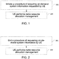
- FIG. 1 is a flowchart of a method implemented by user equipment according to Embodiment 1 of the present invention.
- Embodiment 1 provides a radio resource allocation management method when initiating a procedure for acquiring on-demand system information requested by UE.
- Step 101 a procedure of acquiring on-demand system information requested by UE is initiated.
- Step 103 the UE performs radio resource allocation management; in other words, the UE performs one or more of the following operations:
- Operation 1 applying a default physical layer configuration.
- the default physical layer configuration refers to an RRC configuration predefined by the system for a physical protocol layer. Preferably, it may include one or more from a physical downlink shared channel configuration, a physical uplink control channel configuration, a physical uplink shared channel configuration, an uplink power control configuration, a channel status indication or channel quality indication configuration, an uplink sounding reference signal configuration, and an antenna information configuration service request configuration.
- Operation 2 applying a default Medium Access Control (MAC) main configuration, which is also referred to as MAC configuration for short.
- the default MAC main configuration refers to an RRC configuration predefined by the system for a MAC protocol layer. Preferably, it may include one or more from a maximum number of HARQ transmissions, a buffer status report configuration, a discontinuous transmission configuration, a power headroom report configuration and so on.
- the semi-persistent scheduling configuration may also be called a configured grant, which may include a configured grant provided through RRC signaling and a grant provided through a Physical Downlink Control Channel (PDCCH) signaling (or known as a Downlink Control Information (DCI) signaling).
- a configured grant may include a configured grant provided through RRC signaling and a grant provided through a Physical Downlink Control Channel (PDCCH) signaling (or known as a Downlink Control Information (DCI) signaling).
- PDCH Physical Downlink Control Channel
- DCI Downlink Control Information
- the aforementioned default configuration refers to a predefined default configuration. These default configurations may adopt the same configuration parameters as those used during the initial access, or they may be default configurations set specifically for system information requests. The present invention does not specify particular values in the default configuration.
- the phrase "when initiating a procedure for acquiring on-demand system information requested by UE” in Embodiment 1 may also be phrased as "when the UE requesting system information.”
- the phrase "when adopting the system information acquisition method based on Message 3” may also be phrased as "when initiating transmission of RRC system information request message.”
- FIG. 2 is a flowchart of a method implemented by user equipment according to Embodiment 2 of the present invention.
- Embodiment 2 provides a radio resource allocation management method when ending a procedure of requesting on-demand system information by UE.
- Step 201 a procedure of requesting on-demand system information by UE is ended.
- Step 203 the UE performs radio resource allocation management; in other words, the UE performs one or more of the following operations:
- the default physical layer configuration, the default MAC main configuration, and the default semi-persistent scheduling configuration in the aforementioned operations are the same as those in the embodiments, which are not repeated herein.
- the phrase "when the UE ends a procedure of system information request” may refer to that the system information request procedure ends in success, or may also refer to that the system information request procedure ends in failure. Therefore, the phrase “when the UE ends a procedure of system information request” may also be phrased as " when a confirmation of system information request from a lower layer is received” or "when a confirmation of RRC system information request message from a lower layer is received” or " when a random access failure indication from a lower layer is received” or "when a random access for system information request fails.”
- FIG. 3 is a flowchart of a method implemented by user equipment according to Embodiment 3 of the present invention.
- This embodiment provides a radio resource allocation management method when a cell reselection occurs during a procedure of requesting on-demand system information by the UE.
- Step 301 a cell reselection occurs during a procedure of requesting on-demand system information by the UE.
- Step 303 the UE performs radio resource allocation management; in other words, the UE performs one or more of the following operations:
- the default physical layer configuration, the default MAC main configuration, and the default semi-persistent scheduling configuration in the aforementioned operations are the same as those in the embodiments, which are not repeated herein.
- the phrase “during a procedure of requesting on-demand system information by the UE” may also be phrased as "before receiving a confirmation of a system information request from a lower layer” or “before receiving a confirmation for an RRC system information request from a lower layer” or "before the completion of a random access procedure for a system information request.”
- the completion of a random access procedure may refer to a successful completion of the random access procedure or an unsuccessful completion of the random access procedure.
- FIG. 4 is a flowchart of a method implemented by user equipment according to Embodiment 4 of the present invention.
- Embodiment 4 provides a radio resource allocation management method when the UE interrupts the system information request procedure during a procedure of requesting on-demand system information by the UE.
- Step 401 during a procedure of requesting on-demand system information by the UE, the UE interrupts the system information request procedure.
- Step 403 the UE performs radio resource allocation management; in other words, the UE performs one or more of the following operations:
- the default physical layer configuration, the default MAC main configuration, and the default semi-persistent scheduling configuration in the aforementioned operations are the same as those in the embodiments, which are not repeated herein.
- the phrase “during a procedure of requesting on-demand system information by the UE” may also be phrased as " before receiving a confirmation of a system information request from a lower layer” or “before receiving a confirmation for an RRC system information request from a lower layer” or "before the completion of a random access procedure for a system information request.”
- the completion of a random access procedure may refer to a successful completion of the random access procedure or an unsuccessful completion of the random access procedure.
- the UE interrupting the system information request procedure may occur, for example, when the upper layer of the UE ends an application or is not interested in an application, then the UE stops requesting the corresponding system information.
- the phrase "when the UE interrupts the system information request procedure" may also be phrased as "when the system information request procedure is interrupted/suspended/abandoned" or "when the system information request procedure is abandoned.”
- This embodiment provides a method for determining a random access resource in a system information request procedure based on Message 1.
- the random access resource refers to a PRACH resource or a RACH resource used to send a preamble for a system information request.
- the following SI may also be replaced with SIB.
- Step 1 the UE receives a scheduling information list (schedulinginfoList) of multiple SI and a random access resource list for system information request through SIB 1.
- the scheduling information includes current system information broadcast status indication information of the SI, such as whether it is on-demand or being broadcast.
- Step 2 if the random access resource list for system information request includes only one (or regarded as one entry of) random access resource, then the UE determines that the configuration of the random access resource is applicable to all SI with the current system information broadcast status indication information configured as on-demand. Conversely, if the random access resource list for system information request includes multiple (or regarded as multiple entries of) random access resources, then the number of entries and arrangement order in the random access resource list are preferably the same as the number of entries and arrangement order in the scheduling information list. That is, a first entry in the random access resource list corresponds to a first entry in the scheduling information list, a second entry in the random access resource list corresponds to a second entry in the scheduling information list, and so forth.
- the number of entries and arrangement order in the random access resource list are the same as the number of a plurality of entries and arrangement order in the scheduling information list where the system information broadcast status indication information is configured as on-demand. That is, a first entry in the random access resource list corresponds to a first entry where the system information broadcast status indication information is configured as on-demand in the scheduling information list, a second entry in the random access resource list corresponds to a second entry where the system information broadcast status indication information is configured as on-demand in the scheduling information list, and so forth.
- base station refers to mobile communication data and control switching centers with large transmission power and wide coverage area, including functions such as resource allocation scheduling, data receiving and transmission.
- User equipment refers to user equipment for a user, such as terminal equipment that can carry out wireless communication with base stations or micro base stations, such as mobile phones and notebooks.
- the method and related equipment of the present invention have already been described above with reference to the preferred embodiments. Those skilled in the art can understand that the method shown above is merely illustrative. The method of the invention is not limited to the steps and sequence shown above.
- the base station and user equipment shown above may include more modules, such as modules that can be developed or will be developed in the future that can be used for a base station, MME, or UE and so on.
- the various symbols shown above are merely illustrative and are not restrictive. The present invention is not limited to any specific cells which serve as examples of these symbols. Those skilled in the art can make many variations and modifications based on the teachings of the illustrated embodiments.
- FIG. 5 is a block diagram representing user equipment (UE) involved in an embodiment of the present invention.
- the user equipment UE50 includes a processor 501 and a memory 502.
- the processor 501 may include, for example, a microprocessor, a microcontroller, an embedded processor, and the like.
- the memory 502 may include, for example, a volatile memory (such as a random access memory (RAM)), a hard disk drive (HDD), a non-volatile memory (such as a flash memory), or other memories.
- the memory 502 stores program instructions. When run by the processor 501, the instructions can execute the above method executed by the user equipment described in detail in the present disclosure.
- the program running in the device according to the present invention may be a program that enables a computer to implement the functions of the embodiments of the present invention by controlling a central processing unit (CPU).
- the program or information processed by the program may be temporarily stored in a volatile memory (such as a Random Access Memory (RAM)), a Hard Disk Drive (HDD), a non-volatile memory (such as a flash memory), or another memory system.
- RAM Random Access Memory
- HDD Hard Disk Drive
- non-volatile memory such as a flash memory
- Programs for fulfilling the functions of the various embodiments of the present invention may be recorded in a computer-readable recording medium. Corresponding functions may be fulfilled by causing a computer system to read the programs recorded in the recording medium and execute these programs.
- the so-called “computer system” here may be a computer system embedded in the device, and may include an operating system or hardware (such as peripheral devices).
- the "computer-readable recording medium” may be a semiconductor recording medium, an optical recording medium, a magnetic recording medium, a recording medium storing a program dynamically for a short time, or any other recording medium readable by a computer.
- circuits for example, single-chip or multi-chip integrated circuits.
- Circuits designed to execute the functions described in this specification may include a general-purpose processor, a Digital Signal Processor (DSP), an Application-Specific Integrated Circuit (ASIC), a Field Programmable Gate Array (FPGA), or another programmable logic device, a discrete gate or transistor logic, a discrete hardware component, or any combination of the above devices.
- the general-purpose processor may be a microprocessor, or any existing processor, controller, microcontroller, or state machine.
- the above circuit may be a digital circuit or an analog circuit. In the case of new integrated circuit technologies that replace existing integrated circuits because of advancements in the semiconductor technologies, one or a plurality of embodiments of the present invention may also be implemented using these new integrated circuit technologies.
- the present invention is not limited to the above embodiments. Various examples of the embodiments have been described; however, the present invention is not limited thereto.
- Fixed or non-mobile electronic devices mounted indoors or outdoors may be used as terminal devices or communication devices, such as AV devices, kitchen devices, cleaning devices, air conditioners, office devices, vending machines, and other household appliances.
Landscapes
- Engineering & Computer Science (AREA)
- Computer Networks & Wireless Communication (AREA)
- Signal Processing (AREA)
- Computer Security & Cryptography (AREA)
- Mobile Radio Communication Systems (AREA)
- Reduction Or Emphasis Of Bandwidth Of Signals (AREA)
Abstract
Description
- The present invention relates to the technical field of radio communication, and in particular, the present invention relates to a method implemented by user equipment and the corresponding user equipment.
- At the 3rd Generation Partnership Project (3GPP) RAN#75 plenary session held in March 2016, NTT DOCOMO proposed a new research project on 5G technology standards (see non-patent document RP-170847: New WID on New Radio Access Technology) and the project was approved. The purpose of this research project was to develop a New Radio (NR) access technology to meet all application scenarios, requirements, and deployment environments of 5G. In this research project, NR mainly included two application scenarios: Enhanced Mobile Broadband (eMBB) and Ultra Reliable and Low Latency Communications (URLLC). According to the plans of the research project, the standardization of NR would be carried out in two phases: the first phase of standardization would be completed in mid-2018; and the second phase of standardization would be completed by the end of 2019. For the first phase, the standard specifications should be forward compatible with the standard specifications of the second phase. For the second phase, the standard specifications should be based on the standard specifications of the first phase and meet all the requirements of the 5G NR technical standards.
- In addition to continuing to utilize the method in the long-term evolution (LTE) system where the network side actively transmits cell system information to user equipment (UE) through broadcasting or dedicated signaling, a new system information transmission method is further introduced in NR, namely, on-demand system information transmission as requested by UE. The system information in the NR system is divided into two parts: minimum system information and on-demand system information. The minimum system information includes basic information of the cell used for UE camping and initial access, and usually includes a Master Information Block (MIB) and System Information Block Type 1 (SIB1). The on-demand system information refers to System Information Blocks (SIBs) other than the minimum system information, such as System
Information Block Type 3 and so on. Multiple SIBs with the same transmission cycle can be combined to be transmitted as a Radio Resource Control (RRC) message, which is known as a System Information (SI) message. The on-demand system information may adopt a cyclic broadcast method in like manner with the minimum system information and may also adopt a method in which a transmission is carried out as requested by the UE; a base station broadcasts system information broadcast status indication information to inform the UE as to whether the SIB or SI is on-demand or being broadcast. The content contained in each system information block is not detailed in the present invention. For details, please refer to 3GPP Technical Specification Document 38.331. The NR system supports adoption of a transmission method based on a UE request for the aforementioned on-demand system information. In the present invention, a solution for the problem of how to implement a system information transmission method based on a UE request is proposed. - The present invention has been proposed in an effort to solve at least some of the aforementioned problems in the prior art. The present invention provides a method implemented by user equipment and user equipment thereof, which may effectively implement radio resource allocation management during a procedure of requesting on-demand system information by UE.
- According to the present invention, a method implemented by user equipment is proposed, the method comprising: initiating a procedure of acquiring on-demand system information requested by user equipment; and performing radio resource allocation management, wherein the step of performing radio resource allocation management comprises performing one or more of the following operations: applying a default physical layer configuration; applying default medium access control; and applying a default semi-persistent scheduling configuration.
- Preferably, the initiating a procedure of acquiring on-demand system information requested by user equipment comprises transmission of system information requested by user equipment or a message for initiating a radio resource control system information request.
- In addition, according to the present invention, a method implemented by user equipment is proposed, the method comprising: ending a procedure of requesting on-demand system information by user equipment; and performing radio resource allocation management, wherein the step of performing radio resource allocation management comprises performing one or more of the following operations: releasing a default physical layer configuration; releasing a default medium access control configuration; and releasing a default semi-persistent scheduling configuration and implementing reconstruction of a radio link control layer corresponding to a radio bearer.
- Preferably, the ending a procedure of requesting on-demand system information by UE comprises: receiving a confirmation of a system information request from a lower layer, receiving a confirmation of a radio resource control system information request message from a lower layer, receiving an indication of random access failure from a lower layer, or random access failure for system information request.
- In addition, according to the present invention, a method implemented by user equipment is proposed, the method comprising: initiating cell reselection in a procedure of requesting on-demand system information by user equipment; and performing radio resource allocation management, wherein the step of performing radio resource allocation management comprises performing one or more of the following operations: releasing a default physical layer configuration; releasing a default medium access control configuration; and releasing a default semi-persistent scheduling configuration, implementing reconstruction of a radio link control layer corresponding to a radio bearer, and resetting a media access control.
- Preferably, the "in a process of requesting on-demand system information by user equipment" comprises: before receiving a confirmation of a system information request from a lower layer, before receiving a confirmation of a radio resource control system information request from a lower layer, or before the completion of a procedure of random access for system information request.
- In addition, according to the present invention, a method implemented by user equipment is proposed, the method comprising: initiating user equipment to interrupt a system information request procedure in a procedure of requesting on-demand system information by user equipment; and performing radio resource allocation management, wherein the step of performing radio resource allocation management comprises performing one or more of the following operations: releasing a default physical layer configuration; releasing a default medium access control configuration; and releasing a default semi-persistent scheduling configuration, implementing reconstruction of a radio link control layer corresponding to a radio bearer, and resetting a media access control.
- Preferably, the "in a process of requesting on-demand system information by user equipment" comprises: before receiving a confirmation of a system information request from a lower layer, before receiving a confirmation of a radio resource control system information request from a lower layer, or before the completion of a procedure of random access for system information request.
- Preferably, the user equipment interrupting a system information request procedure comprises the following: the system information request procedure being interrupted/suspended/abandoned, or the system information request procedure being abandoned.
- In addition, according to the present invention, user equipment is proposed, comprising: a processor; and a memory, storing instructions, wherein when run by the processor, the instructions execute the method according to any one of
Claims - According to the present invention, radio resource allocation management may be effectively implemented during a procedure of requesting on-demand system information by UE.
- The above and other features of the present invention will become more apparent through the following detailed description with reference to the accompanying drawings, wherein:
-
FIG. 1 is a flowchart of a method implemented by user equipment according to Embodiment 1 of the present invention. -
FIG. 2 is a flowchart of a method implemented by user equipment according to Embodiment 2 of the present invention. -
FIG. 3 is a flowchart of a method implemented by user equipment according toEmbodiment 3 of the present invention. -
FIG. 4 is a flowchart of a method implemented by user equipment according to Embodiment 4 of the present invention. -
FIG. 5 is a block diagram representing user equipment (UE) involved in an embodiment of the present invention. - The present invention will be described in detail below with reference to the accompanying drawings and specific implementations.
- In the present invention, the terms "including" and "comprising" and their derivatives mean "including but not limited to." The term "or" is inclusive and means and/or.
- In this Description, the following various embodiments for describing the principle of the present disclosure are merely illustrative, and should not be construed as to limit the scope of the present disclosure in any way. The following description with reference to the accompanying drawings is used to facilitate a comprehensive understanding of the illustrative embodiments of the present invention defined by the claims and their equivalents. The following description includes a variety of specific details to facilitate understanding, but these details should be considered as illustrative only. Therefore, those of ordinary skill in the art should recognize that various changes and modifications can be made to the embodiments described herein without departing from the scope and spirit of the present invention. In addition, for clarity and conciseness, descriptions of well-known functions and structures are omitted. In addition, throughout the accompanying drawings, the same reference numerals are used to represent similar functions and operations.
- By taking an NR mobile communication system and subsequent evolved versions thereof as an illustrative application environment, a plurality of implementations according to the present invention are described in detail below. However, it should be pointed out that the present invention is not limited to the following implementations, but can be applied to more other radio communication systems. Unless otherwise specified, in the present invention, the concepts of a cell and a base station may be replaced with each other. The on-demand (requested) system information and the system information based on UE request convey the same intent.
- Some concepts related to the present invention are explained below. It should be noted that some of the names in the following description are merely illustrative and not limiting and other names may also be used.
- Message 1: the first message in the random access procedure, i.e., the random access preamble sent by the UE. The UE obtains the configuration (such as power parameters, number of transmissions, etc.) and resources (such as time-frequency domain resources) required to send Message 1 through system information. As the preamble is sent on the Physical Random Access Channel (PRACH), Message 1 is sometimes referred to as PRACH and the configuration and resources of Message 1 are also referred to as PRACH configuration and PRACH resources. In the present invention, PRACH resources also include PRACH preamble.
- Random Access Response (RAR): the second message in the random access procedure. After receiving the random access preamble of the UE, a base station responds to the reception of the random access preamble by sending a random access response message. The random access response message includes a time advance domain, an uplink grant domain, a UE identifier domain and so on. The random access response is also referred to as Message 2.
- Message 3: the third message in the random access procedure. In the present invention,
Message 3 refers collectively to an uplink transmission sent by the UE on an uplink resource indicated by an uplink grant included in the RAR. - Message 4: in the random access procedure, a downlink message used in response to
Message 3 that is sent by a base station to the UE. The UE performs random access contention resolution based on the message to verify whether this random access is successful. - In the current Technical Specification Document 38.331 approved by 3GPP, an on-demand system information transmission requested by UE requests a system information block as required by the UE from a base station through adopting a random access procedure. Therefore, a request method based on Message 1 and a request method based on
Message 3 exist. In the request method based on Message 1, the base station informs the UE of the PRACH configuration/resource for sending Message 1 through broadcast (such as SIB1); in other words, the PRACH configuration/resource used for the system information request is independent of the initial access or PRACH configuration/resource for other purposes and is configured separately. For example, each SI (or SIB) corresponds to a dedicated PRACH resource. The UE uses a corresponding PRACH resource to send a preamble to inform the base station which SI (or SIB) it wants to obtain. After receiving Message 1, the base station returns a RAR to respond to the request of the UE and broadcast the SI (or SIB) requested by the UE in a subsequent period of time. In the request method based onMessage 3, the aforementioned dedicated PRACH configuration/resource is not configured. The PRACH configuration/resource used by the UE is the same as the PRACH configuration/resource used for the initial access or the other purposes. When the UE wants to obtain one or more SIs (or SIBs), the UE initiates a random access procedure and includes a list of SIs (or SIBs) it wants to acquire inMessage 3 to inform the base station which SIs (or SIBs) it wants to acquire.Message 3 contains an RRC message (such as RRC system information request message, RRCsystemInforequest message) for system information request. After receivingMessage 3, the base station returns Message 4 to respond to the request ofMessage 3 and to resolve contention in the random access procedure. - For the on-demand SIB/SI requested by the UE (i.e., the corresponding system information broadcast status is set to on-demand), when the UE wants to obtain one or more SIB/SI, if SIB1 contains PRACH resources of the SIB/SI that the UE wants to obtain, then the UE adopts a method based on Message 1. The UE triggers a lower layer to use the corresponding PRACH resource to initiate a random access procedure. If a confirmation of the system information request from the lower layer is received, the UE starts to obtain the SIB/SI according to the scheduling information of the SIB/SI. Conversely, if the SIB1 does not contain the PRACH resources of the SIB/SI that the UE wants to obtain, then the UE adopts the method based on
Message 3. The UE initiates a transmission of RRC system information request message. If a confirmation for the RRC system information request message from the lower layer is received, the UE starts to obtain the SIB/SI according to the scheduling information of the SIB/SI. - Regardless of the fact as to whether the system information acquisition method is based on Message 1 or
Message 3, the UE needs to carry out transmission according to a certain radio resource allocation such as a protocol layer allocation when transmitting and receiving. Based on the above understanding, the problems to be solved by the present invention are as follows: how to configure the radio resource allocation in a procedure of requesting on-demand system information by the UE and how to manage radio resource allocation under different circumstances such as when carrying out cell reselection. -
FIG. 1 is a flowchart of a method implemented by user equipment according to Embodiment 1 of the present invention. - Embodiment 1 provides a radio resource allocation management method when initiating a procedure for acquiring on-demand system information requested by UE.
- As shown in
FIG. 1 , inStep 101, a procedure of acquiring on-demand system information requested by UE is initiated. - When initiating a procedure for acquiring on-demand system information requested by UE, in
Step 103, the UE performs radio resource allocation management; in other words, the UE performs one or more of the following operations: - Operation 1: applying a default physical layer configuration. The default physical layer configuration refers to an RRC configuration predefined by the system for a physical protocol layer. Preferably, it may include one or more from a physical downlink shared channel configuration, a physical uplink control channel configuration, a physical uplink shared channel configuration, an uplink power control configuration, a channel status indication or channel quality indication configuration, an uplink sounding reference signal configuration, and an antenna information configuration service request configuration.
- Operation 2: applying a default Medium Access Control (MAC) main configuration, which is also referred to as MAC configuration for short. The default MAC main configuration refers to an RRC configuration predefined by the system for a MAC protocol layer. Preferably, it may include one or more from a maximum number of HARQ transmissions, a buffer status report configuration, a discontinuous transmission configuration, a power headroom report configuration and so on.
- Operation 3: applying a default semi-persistent scheduling configuration. The semi-persistent scheduling configuration may also be called a configured grant, which may include a configured grant provided through RRC signaling and a grant provided through a Physical Downlink Control Channel (PDCCH) signaling (or known as a Downlink Control Information (DCI) signaling).
- The aforementioned default configuration refers to a predefined default configuration. These default configurations may adopt the same configuration parameters as those used during the initial access, or they may be default configurations set specifically for system information requests. The present invention does not specify particular values in the default configuration.
- The phrase "when initiating a procedure for acquiring on-demand system information requested by UE" in Embodiment 1 may also be phrased as "when the UE requesting system information." The phrase "when adopting the system information acquisition method based on
Message 3" may also be phrased as "when initiating transmission of RRC system information request message." -
FIG. 2 is a flowchart of a method implemented by user equipment according to Embodiment 2 of the present invention. - Embodiment 2 provides a radio resource allocation management method when ending a procedure of requesting on-demand system information by UE.
- As shown in
FIG. 2 , inStep 201, a procedure of requesting on-demand system information by UE is ended. - When the UE ends a procedure of requesting system information, in
Step 203, the UE performs radio resource allocation management; in other words, the UE performs one or more of the following operations: - Operation 1: releasing a default physical layer configuration.
- Operation 2: releasing a default MAC configuration.
- Operation 3: releasing a default semi-persistent scheduling configuration.
- Operation 4: performing a reconstruction of a Radio Link Control (RLC) layer corresponding to a radio bearer. Preferably, the radio bearer refers to Signaling Radio Bearer 0; alternatively, the radio bearer refers to all radio bearers, including SRB and Data Radio Bearer (DRB).
- The default physical layer configuration, the default MAC main configuration, and the default semi-persistent scheduling configuration in the aforementioned operations are the same as those in the embodiments, which are not repeated herein.
- In Embodiment 2, the phrase "when the UE ends a procedure of system information request" may refer to that the system information request procedure ends in success, or may also refer to that the system information request procedure ends in failure. Therefore, the phrase "when the UE ends a procedure of system information request" may also be phrased as " when a confirmation of system information request from a lower layer is received" or "when a confirmation of RRC system information request message from a lower layer is received" or " when a random access failure indication from a lower layer is received" or "when a random access for system information request fails."
-
FIG. 3 is a flowchart of a method implemented by user equipment according toEmbodiment 3 of the present invention. - This embodiment provides a radio resource allocation management method when a cell reselection occurs during a procedure of requesting on-demand system information by the UE.
- As shown in
FIG. 3 , inStep 301, a cell reselection occurs during a procedure of requesting on-demand system information by the UE. - During a procedure of requesting on-demand system information by the UE, when a cell reselection occurs, in
Step 303, the UE performs radio resource allocation management; in other words, the UE performs one or more of the following operations: - Operation 1: releasing a default physical layer configuration.
- Operation 2: releasing a default MAC configuration.
- Operation 3: releasing a default semi-persistent scheduling configuration.
- Operation 4: performing a reconstruction of a Radio Link Control (RLC) layer corresponding to a radio bearer. Preferably, the radio bearer refers to Signaling Radio Bearer 0; alternatively, the radio bearer refers to radio bearers that have already been set up, including SRB and Data Radio Bearer (DRB).
- Operation 5: resetting MAC. For details on resetting the MAC, see 3GPP Technical Specification Document 38.321, which is not repeated herein.
- The default physical layer configuration, the default MAC main configuration, and the default semi-persistent scheduling configuration in the aforementioned operations are the same as those in the embodiments, which are not repeated herein.
- In
Embodiment 3, the phrase "during a procedure of requesting on-demand system information by the UE" may also be phrased as "before receiving a confirmation of a system information request from a lower layer" or "before receiving a confirmation for an RRC system information request from a lower layer" or "before the completion of a random access procedure for a system information request." The completion of a random access procedure may refer to a successful completion of the random access procedure or an unsuccessful completion of the random access procedure. -
FIG. 4 is a flowchart of a method implemented by user equipment according to Embodiment 4 of the present invention. - Embodiment 4 provides a radio resource allocation management method when the UE interrupts the system information request procedure during a procedure of requesting on-demand system information by the UE.
- As shown in
FIG. 4 , inStep 401, during a procedure of requesting on-demand system information by the UE, the UE interrupts the system information request procedure. - During a procedure of requesting on-demand system information by the UE, when the UE interrupts the system information request procedure, in
Step 403, the UE performs radio resource allocation management; in other words, the UE performs one or more of the following operations: - Operation 1: releasing a default physical layer configuration.
- Operation 2: releasing a default MAC configuration.
- Operation 3: releasing a default semi-persistent scheduling configuration.
- Operation 4: performing a reconstruction of a Radio Link Control (RLC) layer corresponding to a radio bearer. Preferably, the radio bearer refers to Signaling Radio Bearer 0; alternatively, the radio bearer refers to radio bearers that have already been set up, including SRB and Data Radio Bearer (DRB).
- Operation 5: resetting MAC. For details on resetting the MAC, see 3GPP Technical Specification Document 38.321, which is not repeated herein.
- The default physical layer configuration, the default MAC main configuration, and the default semi-persistent scheduling configuration in the aforementioned operations are the same as those in the embodiments, which are not repeated herein.
- In Embodiment 4, the phrase "during a procedure of requesting on-demand system information by the UE" may also be phrased as " before receiving a confirmation of a system information request from a lower layer" or "before receiving a confirmation for an RRC system information request from a lower layer" or "before the completion of a random access procedure for a system information request." The completion of a random access procedure may refer to a successful completion of the random access procedure or an unsuccessful completion of the random access procedure.
- In Embodiment 4, the UE interrupting the system information request procedure may occur, for example, when the upper layer of the UE ends an application or is not interested in an application, then the UE stops requesting the corresponding system information. The phrase "when the UE interrupts the system information request procedure" may also be phrased as "when the system information request procedure is interrupted/suspended/abandoned" or "when the system information request procedure is abandoned."
- This embodiment provides a method for determining a random access resource in a system information request procedure based on Message 1. The random access resource refers to a PRACH resource or a RACH resource used to send a preamble for a system information request. The following SI may also be replaced with SIB.
- Step 1: the UE receives a scheduling information list (schedulinginfoList) of multiple SI and a random access resource list for system information request through SIB 1. The scheduling information includes current system information broadcast status indication information of the SI, such as whether it is on-demand or being broadcast.
- Step 2: if the random access resource list for system information request includes only one (or regarded as one entry of) random access resource, then the UE determines that the configuration of the random access resource is applicable to all SI with the current system information broadcast status indication information configured as on-demand. Conversely, if the random access resource list for system information request includes multiple (or regarded as multiple entries of) random access resources, then the number of entries and arrangement order in the random access resource list are preferably the same as the number of entries and arrangement order in the scheduling information list. That is, a first entry in the random access resource list corresponds to a first entry in the scheduling information list, a second entry in the random access resource list corresponds to a second entry in the scheduling information list, and so forth. Alternatively, the number of entries and arrangement order in the random access resource list are the same as the number of a plurality of entries and arrangement order in the scheduling information list where the system information broadcast status indication information is configured as on-demand. That is, a first entry in the random access resource list corresponds to a first entry where the system information broadcast status indication information is configured as on-demand in the scheduling information list, a second entry in the random access resource list corresponds to a second entry where the system information broadcast status indication information is configured as on-demand in the scheduling information list, and so forth.
- In the present application, "base station" refers to mobile communication data and control switching centers with large transmission power and wide coverage area, including functions such as resource allocation scheduling, data receiving and transmission. "User equipment" refers to user equipment for a user, such as terminal equipment that can carry out wireless communication with base stations or micro base stations, such as mobile phones and notebooks.
- The method and related equipment of the present invention have already been described above with reference to the preferred embodiments. Those skilled in the art can understand that the method shown above is merely illustrative. The method of the invention is not limited to the steps and sequence shown above. The base station and user equipment shown above may include more modules, such as modules that can be developed or will be developed in the future that can be used for a base station, MME, or UE and so on. The various symbols shown above are merely illustrative and are not restrictive. The present invention is not limited to any specific cells which serve as examples of these symbols. Those skilled in the art can make many variations and modifications based on the teachings of the illustrated embodiments.
-
FIG. 5 is a block diagram representing user equipment (UE) involved in an embodiment of the present invention. As shown inFIG. 5 , the user equipment UE50 includes aprocessor 501 and amemory 502. Theprocessor 501 may include, for example, a microprocessor, a microcontroller, an embedded processor, and the like. Thememory 502 may include, for example, a volatile memory (such as a random access memory (RAM)), a hard disk drive (HDD), a non-volatile memory (such as a flash memory), or other memories. Thememory 502 stores program instructions. When run by theprocessor 501, the instructions can execute the above method executed by the user equipment described in detail in the present disclosure. - The program running in the device according to the present invention may be a program that enables a computer to implement the functions of the embodiments of the present invention by controlling a central processing unit (CPU). The program or information processed by the program may be temporarily stored in a volatile memory (such as a Random Access Memory (RAM)), a Hard Disk Drive (HDD), a non-volatile memory (such as a flash memory), or another memory system.
- Programs for fulfilling the functions of the various embodiments of the present invention may be recorded in a computer-readable recording medium. Corresponding functions may be fulfilled by causing a computer system to read the programs recorded in the recording medium and execute these programs. The so-called "computer system" here may be a computer system embedded in the device, and may include an operating system or hardware (such as peripheral devices). The "computer-readable recording medium" may be a semiconductor recording medium, an optical recording medium, a magnetic recording medium, a recording medium storing a program dynamically for a short time, or any other recording medium readable by a computer.
- Various features or functional modules of the devices used in the above embodiments may be implemented or executed by circuits (for example, single-chip or multi-chip integrated circuits). Circuits designed to execute the functions described in this specification may include a general-purpose processor, a Digital Signal Processor (DSP), an Application-Specific Integrated Circuit (ASIC), a Field Programmable Gate Array (FPGA), or another programmable logic device, a discrete gate or transistor logic, a discrete hardware component, or any combination of the above devices. The general-purpose processor may be a microprocessor, or any existing processor, controller, microcontroller, or state machine. The above circuit may be a digital circuit or an analog circuit. In the case of new integrated circuit technologies that replace existing integrated circuits because of advancements in the semiconductor technologies, one or a plurality of embodiments of the present invention may also be implemented using these new integrated circuit technologies.
- In addition, the present invention is not limited to the above embodiments. Various examples of the embodiments have been described; however, the present invention is not limited thereto. Fixed or non-mobile electronic devices mounted indoors or outdoors may be used as terminal devices or communication devices, such as AV devices, kitchen devices, cleaning devices, air conditioners, office devices, vending machines, and other household appliances.
- As described above, the embodiments of the present invention have been described in detail with reference to the accompanying drawings. However, the specific structure is not limited to the above embodiments, and the present invention also includes any design changes that do not deviate from the gist of the present invention. In addition, various modifications may be made to the present invention within the scope of the claims, and embodiments obtained by appropriately combining the technical means disclosed in different embodiments are also included in the technical scope of the present invention. In addition, the components having the same effects described in the above embodiments may be substituted for each other.
Claims (2)
- A method implemented by user equipment (UE), the method comprising:receiving an SI scheduling information list for a plurality of system information (SI) messages and a random access resource list for a system information request through a system information block 1, i.e., SIB1, wherein each entry of the SI scheduling information list comprises an SI broadcast status indication, so as to indicate whether an SI message is on-demand or being broadcast;determining, if more than one random access resource entry exists in the random access resource list for the system information request, that a first entry in the random access resource list for the system information request corresponds to a first entry in the SI scheduling information list for which the SI broadcast status indication is configured as on-demand, and that a second entry in the random access resource list for system information request corresponds to a second entry in the SI scheduling information list for which the SI broadcast status indication is configured as on-demand.
- User equipment, comprising:a processor; anda memory, storing instructions, whereinwhen run by the processor, the instructions execute the method according to Claim 1.
Applications Claiming Priority (2)
| Application Number | Priority Date | Filing Date | Title |
|---|---|---|---|
| CN201810585298.5A CN110582089B (en) | 2018-06-07 | 2018-06-07 | Method for transmitting system information and user equipment |
| PCT/CN2019/090293 WO2019233472A1 (en) | 2018-06-07 | 2019-06-06 | Method implemented by user equipment, and user equipment |
Publications (3)
| Publication Number | Publication Date |
|---|---|
| EP3806562A1 true EP3806562A1 (en) | 2021-04-14 |
| EP3806562A4 EP3806562A4 (en) | 2022-03-16 |
| EP3806562B1 EP3806562B1 (en) | 2023-01-25 |
Family
ID=68770803
Family Applications (1)
| Application Number | Title | Priority Date | Filing Date |
|---|---|---|---|
| EP19815312.4A Active EP3806562B1 (en) | 2018-06-07 | 2019-06-06 | Method of system information transmissions and user equipment |
Country Status (8)
| Country | Link |
|---|---|
| US (1) | US11445528B2 (en) |
| EP (1) | EP3806562B1 (en) |
| KR (1) | KR102812131B1 (en) |
| CN (1) | CN110582089B (en) |
| BR (1) | BR112020024789A2 (en) |
| ES (1) | ES2939498T3 (en) |
| PL (1) | PL3806562T3 (en) |
| WO (1) | WO2019233472A1 (en) |
Families Citing this family (4)
| Publication number | Priority date | Publication date | Assignee | Title |
|---|---|---|---|---|
| CN110636578B (en) * | 2018-06-21 | 2023-10-31 | 中兴通讯股份有限公司 | A method, device, storage medium and terminal for requesting system messages |
| CN111465115A (en) * | 2019-01-22 | 2020-07-28 | 夏普株式会社 | Radio link control layer reset method and user equipment |
| US11659380B1 (en) * | 2021-05-05 | 2023-05-23 | T-Mobile Usa, Inc. | UE-capability-based system information block transmission |
| WO2024031498A1 (en) * | 2022-08-11 | 2024-02-15 | Qualcomm Incorporated | Techniques for system information block 1 request configurations |
Family Cites Families (13)
| Publication number | Priority date | Publication date | Assignee | Title |
|---|---|---|---|---|
| JP2018041995A (en) | 2015-01-28 | 2018-03-15 | シャープ株式会社 | Terminal apparatus, base station apparatus and method |
| US10136372B2 (en) * | 2015-09-22 | 2018-11-20 | Lg Electronics Inc. | Relay UE selecting method performed by UE in wireless communication system and UE using the same |
| WO2017078466A1 (en) * | 2015-11-04 | 2017-05-11 | 엘지전자 주식회사 | Cell selection/re-selection method for inter-frequency sidelink operation executed by terminal in wireless communication system, and terminal using said method |
| CN109804569B (en) * | 2016-05-11 | 2021-12-07 | 索尼公司 | Distributed control in a wireless system |
| WO2018022570A1 (en) * | 2016-07-27 | 2018-02-01 | Sharp Laboratories Of America, Inc. | On-demand system information for wireless telecommunications |
| SG11201900775UA (en) * | 2016-08-12 | 2019-02-27 | Mediatek Inc | System information acquisition |
| US10383035B2 (en) * | 2016-09-29 | 2019-08-13 | Sharp Laboratories Of America, Inc. | Providing and obtaining system information for remote wireless terminal |
| JP2019208082A (en) * | 2016-09-29 | 2019-12-05 | シャープ株式会社 | Terminal device, base station device, communication method, and integrated circuit |
| US10531268B2 (en) * | 2016-11-17 | 2020-01-07 | Lg Electronics Inc. | Method and apparatus for transceiving a warning message in a wireless communication system |
| US10327264B2 (en) * | 2017-03-20 | 2019-06-18 | Motorola Mobility Llc | Determining a request for system information |
| US10505799B2 (en) * | 2017-03-20 | 2019-12-10 | Motorola Mobility Llc | System information for changing a configuration |
| US11160011B2 (en) * | 2017-08-08 | 2021-10-26 | Lg Electronics Inc. | Method and apparatus for reducing system information acquisition time in wireless communication system |
| US10904910B2 (en) * | 2018-04-12 | 2021-01-26 | FG Innovation Company Limited | System information modification and acquisition procedure |
-
2018
- 2018-06-07 CN CN201810585298.5A patent/CN110582089B/en active Active
-
2019
- 2019-06-06 ES ES19815312T patent/ES2939498T3/en active Active
- 2019-06-06 PL PL19815312.4T patent/PL3806562T3/en unknown
- 2019-06-06 WO PCT/CN2019/090293 patent/WO2019233472A1/en not_active Ceased
- 2019-06-06 BR BR112020024789-8A patent/BR112020024789A2/en unknown
- 2019-06-06 KR KR1020217000091A patent/KR102812131B1/en active Active
- 2019-06-06 EP EP19815312.4A patent/EP3806562B1/en active Active
- 2019-06-06 US US16/972,892 patent/US11445528B2/en active Active
Also Published As
| Publication number | Publication date |
|---|---|
| CN110582089A (en) | 2019-12-17 |
| ES2939498T3 (en) | 2023-04-24 |
| KR102812131B1 (en) | 2025-05-26 |
| PL3806562T3 (en) | 2023-05-15 |
| BR112020024789A2 (en) | 2021-03-02 |
| KR20210018418A (en) | 2021-02-17 |
| US20210258986A1 (en) | 2021-08-19 |
| EP3806562B1 (en) | 2023-01-25 |
| EP3806562A4 (en) | 2022-03-16 |
| US11445528B2 (en) | 2022-09-13 |
| WO2019233472A1 (en) | 2019-12-12 |
| CN110582089B (en) | 2023-06-23 |
Similar Documents
| Publication | Publication Date | Title |
|---|---|---|
| CN111165060B (en) | Random access method, device and communication system | |
| CN104601276B (en) | Method of handling coverage enhancement in a wireless communication system | |
| US11974175B2 (en) | Handover control method and communications device | |
| US10623981B2 (en) | Information transmission method, apparatus, and system | |
| EP3439407A1 (en) | Base station, user equipment, and associated method | |
| KR102861935B1 (en) | Data transmission method and device and communication system | |
| US20240276538A1 (en) | Random access method and apparatus | |
| WO2017133353A1 (en) | Service transmission method and apparatus | |
| US20240313896A1 (en) | Communication method and device | |
| JP7468595B2 (en) | Base station device, terminal device and communication system | |
| US20200178344A1 (en) | Resource Configuration Method And Device | |
| US11445528B2 (en) | Method implemented by user equipment and user equipment | |
| AU2018311884B2 (en) | Method and device for resetting media access control layer | |
| US12568524B2 (en) | Random access method, and electronic device and storage medium | |
| JP2020502918A (en) | Uplink transmission control method and apparatus, and communication system | |
| US12273891B2 (en) | Method processing for split resources and processing device | |
| JP7605963B2 (en) | Method and apparatus for data transmission - Patents.com | |
| JP7347664B2 (en) | Wireless communication methods, devices and systems | |
| WO2019213974A1 (en) | Method for message transmission in random access process and related device | |
| KR20260072625A (en) | Cell handover method, terminal device and network device | |
| WO2026000307A1 (en) | Methods and apparatuses for wireless communication |
Legal Events
| Date | Code | Title | Description |
|---|---|---|---|
| STAA | Information on the status of an ep patent application or granted ep patent |
Free format text: STATUS: THE INTERNATIONAL PUBLICATION HAS BEEN MADE |
|
| PUAI | Public reference made under article 153(3) epc to a published international application that has entered the european phase |
Free format text: ORIGINAL CODE: 0009012 |
|
| STAA | Information on the status of an ep patent application or granted ep patent |
Free format text: STATUS: REQUEST FOR EXAMINATION WAS MADE |
|
| 17P | Request for examination filed |
Effective date: 20210107 |
|
| AK | Designated contracting states |
Kind code of ref document: A1 Designated state(s): AL AT BE BG CH CY CZ DE DK EE ES FI FR GB GR HR HU IE IS IT LI LT LU LV MC MK MT NL NO PL PT RO RS SE SI SK SM TR |
|
| AX | Request for extension of the european patent |
Extension state: BA ME |
|
| DAV | Request for validation of the european patent (deleted) | ||
| DAX | Request for extension of the european patent (deleted) | ||
| A4 | Supplementary search report drawn up and despatched |
Effective date: 20220214 |
|
| RIC1 | Information provided on ipc code assigned before grant |
Ipc: H04W 72/04 20090101ALN20220208BHEP Ipc: H04W 74/08 20090101ALI20220208BHEP Ipc: H04W 74/00 20090101ALI20220208BHEP Ipc: H04W 48/14 20090101AFI20220208BHEP |
|
| RIC1 | Information provided on ipc code assigned before grant |
Ipc: H04W 72/04 20090101ALN20220706BHEP Ipc: H04W 74/08 20090101ALI20220706BHEP Ipc: H04W 74/00 20090101ALI20220706BHEP Ipc: H04W 48/14 20090101AFI20220706BHEP |
|
| REG | Reference to a national code |
Ref country code: DE Ref legal event code: R079 Ref document number: 602019024867 Country of ref document: DE Free format text: PREVIOUS MAIN CLASS: H04W0072040000 Ipc: H04W0048140000 |
|
| GRAP | Despatch of communication of intention to grant a patent |
Free format text: ORIGINAL CODE: EPIDOSNIGR1 |
|
| STAA | Information on the status of an ep patent application or granted ep patent |
Free format text: STATUS: GRANT OF PATENT IS INTENDED |
|
| RIC1 | Information provided on ipc code assigned before grant |
Ipc: H04W 72/04 20090101ALN20220825BHEP Ipc: H04W 74/08 20090101ALI20220825BHEP Ipc: H04W 74/00 20090101ALI20220825BHEP Ipc: H04W 48/14 20090101AFI20220825BHEP |
|
| INTG | Intention to grant announced |
Effective date: 20220909 |
|
| RAP3 | Party data changed (applicant data changed or rights of an application transferred) |
Owner name: FG INNOVATION COMPANY LIMITED Owner name: SHARP KABUSHIKI KAISHA |
|
| GRAS | Grant fee paid |
Free format text: ORIGINAL CODE: EPIDOSNIGR3 |
|
| GRAA | (expected) grant |
Free format text: ORIGINAL CODE: 0009210 |
|
| STAA | Information on the status of an ep patent application or granted ep patent |
Free format text: STATUS: THE PATENT HAS BEEN GRANTED |
|
| AK | Designated contracting states |
Kind code of ref document: B1 Designated state(s): AL AT BE BG CH CY CZ DE DK EE ES FI FR GB GR HR HU IE IS IT LI LT LU LV MC MK MT NL NO PL PT RO RS SE SI SK SM TR |
|
| REG | Reference to a national code |
Ref country code: GB Ref legal event code: FG4D |
|
| REG | Reference to a national code |
Ref country code: CH Ref legal event code: EP |
|
| REG | Reference to a national code |
Ref country code: DE Ref legal event code: R096 Ref document number: 602019024867 Country of ref document: DE |
|
| REG | Reference to a national code |
Ref country code: AT Ref legal event code: REF Ref document number: 1546625 Country of ref document: AT Kind code of ref document: T Effective date: 20230215 Ref country code: IE Ref legal event code: FG4D |
|
| REG | Reference to a national code |
Ref country code: ES Ref legal event code: FG2A Ref document number: 2939498 Country of ref document: ES Kind code of ref document: T3 Effective date: 20230424 |
|
| REG | Reference to a national code |
Ref country code: LT Ref legal event code: MG9D |
|
| REG | Reference to a national code |
Ref country code: NL Ref legal event code: MP Effective date: 20230125 |
|
| REG | Reference to a national code |
Ref country code: AT Ref legal event code: MK05 Ref document number: 1546625 Country of ref document: AT Kind code of ref document: T Effective date: 20230125 |
|
| PG25 | Lapsed in a contracting state [announced via postgrant information from national office to epo] |
Ref country code: NL Free format text: LAPSE BECAUSE OF FAILURE TO SUBMIT A TRANSLATION OF THE DESCRIPTION OR TO PAY THE FEE WITHIN THE PRESCRIBED TIME-LIMIT Effective date: 20230125 |
|
| PG25 | Lapsed in a contracting state [announced via postgrant information from national office to epo] |
Ref country code: RS Free format text: LAPSE BECAUSE OF FAILURE TO SUBMIT A TRANSLATION OF THE DESCRIPTION OR TO PAY THE FEE WITHIN THE PRESCRIBED TIME-LIMIT Effective date: 20230125 Ref country code: PT Free format text: LAPSE BECAUSE OF FAILURE TO SUBMIT A TRANSLATION OF THE DESCRIPTION OR TO PAY THE FEE WITHIN THE PRESCRIBED TIME-LIMIT Effective date: 20230525 Ref country code: NO Free format text: LAPSE BECAUSE OF FAILURE TO SUBMIT A TRANSLATION OF THE DESCRIPTION OR TO PAY THE FEE WITHIN THE PRESCRIBED TIME-LIMIT Effective date: 20230425 Ref country code: LV Free format text: LAPSE BECAUSE OF FAILURE TO SUBMIT A TRANSLATION OF THE DESCRIPTION OR TO PAY THE FEE WITHIN THE PRESCRIBED TIME-LIMIT Effective date: 20230125 Ref country code: LT Free format text: LAPSE BECAUSE OF FAILURE TO SUBMIT A TRANSLATION OF THE DESCRIPTION OR TO PAY THE FEE WITHIN THE PRESCRIBED TIME-LIMIT Effective date: 20230125 Ref country code: HR Free format text: LAPSE BECAUSE OF FAILURE TO SUBMIT A TRANSLATION OF THE DESCRIPTION OR TO PAY THE FEE WITHIN THE PRESCRIBED TIME-LIMIT Effective date: 20230125 Ref country code: AT Free format text: LAPSE BECAUSE OF FAILURE TO SUBMIT A TRANSLATION OF THE DESCRIPTION OR TO PAY THE FEE WITHIN THE PRESCRIBED TIME-LIMIT Effective date: 20230125 |
|
| PG25 | Lapsed in a contracting state [announced via postgrant information from national office to epo] |
Ref country code: SE Free format text: LAPSE BECAUSE OF FAILURE TO SUBMIT A TRANSLATION OF THE DESCRIPTION OR TO PAY THE FEE WITHIN THE PRESCRIBED TIME-LIMIT Effective date: 20230125 Ref country code: IS Free format text: LAPSE BECAUSE OF FAILURE TO SUBMIT A TRANSLATION OF THE DESCRIPTION OR TO PAY THE FEE WITHIN THE PRESCRIBED TIME-LIMIT Effective date: 20230525 Ref country code: GR Free format text: LAPSE BECAUSE OF FAILURE TO SUBMIT A TRANSLATION OF THE DESCRIPTION OR TO PAY THE FEE WITHIN THE PRESCRIBED TIME-LIMIT Effective date: 20230426 Ref country code: FI Free format text: LAPSE BECAUSE OF FAILURE TO SUBMIT A TRANSLATION OF THE DESCRIPTION OR TO PAY THE FEE WITHIN THE PRESCRIBED TIME-LIMIT Effective date: 20230125 |
|
| REG | Reference to a national code |
Ref country code: DE Ref legal event code: R097 Ref document number: 602019024867 Country of ref document: DE |
|
| PG25 | Lapsed in a contracting state [announced via postgrant information from national office to epo] |
Ref country code: SM Free format text: LAPSE BECAUSE OF FAILURE TO SUBMIT A TRANSLATION OF THE DESCRIPTION OR TO PAY THE FEE WITHIN THE PRESCRIBED TIME-LIMIT Effective date: 20230125 Ref country code: RO Free format text: LAPSE BECAUSE OF FAILURE TO SUBMIT A TRANSLATION OF THE DESCRIPTION OR TO PAY THE FEE WITHIN THE PRESCRIBED TIME-LIMIT Effective date: 20230125 Ref country code: EE Free format text: LAPSE BECAUSE OF FAILURE TO SUBMIT A TRANSLATION OF THE DESCRIPTION OR TO PAY THE FEE WITHIN THE PRESCRIBED TIME-LIMIT Effective date: 20230125 Ref country code: DK Free format text: LAPSE BECAUSE OF FAILURE TO SUBMIT A TRANSLATION OF THE DESCRIPTION OR TO PAY THE FEE WITHIN THE PRESCRIBED TIME-LIMIT Effective date: 20230125 Ref country code: CZ Free format text: LAPSE BECAUSE OF FAILURE TO SUBMIT A TRANSLATION OF THE DESCRIPTION OR TO PAY THE FEE WITHIN THE PRESCRIBED TIME-LIMIT Effective date: 20230125 |
|
| PG25 | Lapsed in a contracting state [announced via postgrant information from national office to epo] |
Ref country code: SK Free format text: LAPSE BECAUSE OF FAILURE TO SUBMIT A TRANSLATION OF THE DESCRIPTION OR TO PAY THE FEE WITHIN THE PRESCRIBED TIME-LIMIT Effective date: 20230125 |
|
| PLBE | No opposition filed within time limit |
Free format text: ORIGINAL CODE: 0009261 |
|
| STAA | Information on the status of an ep patent application or granted ep patent |
Free format text: STATUS: NO OPPOSITION FILED WITHIN TIME LIMIT |
|
| 26N | No opposition filed |
Effective date: 20231026 |
|
| PG25 | Lapsed in a contracting state [announced via postgrant information from national office to epo] |
Ref country code: MC Free format text: LAPSE BECAUSE OF FAILURE TO SUBMIT A TRANSLATION OF THE DESCRIPTION OR TO PAY THE FEE WITHIN THE PRESCRIBED TIME-LIMIT Effective date: 20230125 |
|
| PG25 | Lapsed in a contracting state [announced via postgrant information from national office to epo] |
Ref country code: SI Free format text: LAPSE BECAUSE OF FAILURE TO SUBMIT A TRANSLATION OF THE DESCRIPTION OR TO PAY THE FEE WITHIN THE PRESCRIBED TIME-LIMIT Effective date: 20230125 Ref country code: MC Free format text: LAPSE BECAUSE OF FAILURE TO SUBMIT A TRANSLATION OF THE DESCRIPTION OR TO PAY THE FEE WITHIN THE PRESCRIBED TIME-LIMIT Effective date: 20230125 |
|
| REG | Reference to a national code |
Ref country code: CH Ref legal event code: PL |
|
| REG | Reference to a national code |
Ref country code: BE Ref legal event code: MM Effective date: 20230630 |
|
| PG25 | Lapsed in a contracting state [announced via postgrant information from national office to epo] |
Ref country code: LU Free format text: LAPSE BECAUSE OF NON-PAYMENT OF DUE FEES Effective date: 20230606 |
|
| REG | Reference to a national code |
Ref country code: IE Ref legal event code: MM4A |
|
| PG25 | Lapsed in a contracting state [announced via postgrant information from national office to epo] |
Ref country code: LU Free format text: LAPSE BECAUSE OF NON-PAYMENT OF DUE FEES Effective date: 20230606 |
|
| PG25 | Lapsed in a contracting state [announced via postgrant information from national office to epo] |
Ref country code: IE Free format text: LAPSE BECAUSE OF NON-PAYMENT OF DUE FEES Effective date: 20230606 |
|
| PG25 | Lapsed in a contracting state [announced via postgrant information from national office to epo] |
Ref country code: IE Free format text: LAPSE BECAUSE OF NON-PAYMENT OF DUE FEES Effective date: 20230606 Ref country code: CH Free format text: LAPSE BECAUSE OF NON-PAYMENT OF DUE FEES Effective date: 20230630 |
|
| PG25 | Lapsed in a contracting state [announced via postgrant information from national office to epo] |
Ref country code: IT Free format text: LAPSE BECAUSE OF FAILURE TO SUBMIT A TRANSLATION OF THE DESCRIPTION OR TO PAY THE FEE WITHIN THE PRESCRIBED TIME-LIMIT Effective date: 20230125 Ref country code: BE Free format text: LAPSE BECAUSE OF NON-PAYMENT OF DUE FEES Effective date: 20230630 |
|
| PG25 | Lapsed in a contracting state [announced via postgrant information from national office to epo] |
Ref country code: BG Free format text: LAPSE BECAUSE OF FAILURE TO SUBMIT A TRANSLATION OF THE DESCRIPTION OR TO PAY THE FEE WITHIN THE PRESCRIBED TIME-LIMIT Effective date: 20230125 |
|
| PG25 | Lapsed in a contracting state [announced via postgrant information from national office to epo] |
Ref country code: BG Free format text: LAPSE BECAUSE OF FAILURE TO SUBMIT A TRANSLATION OF THE DESCRIPTION OR TO PAY THE FEE WITHIN THE PRESCRIBED TIME-LIMIT Effective date: 20230125 |
|
| REG | Reference to a national code |
Ref country code: DE Ref legal event code: R081 Ref document number: 602019024867 Country of ref document: DE Owner name: SHARP KABUSHIKI KAISHA, SAKAI CITY, JP Free format text: FORMER OWNERS: FG INNOVATION COMPANY LIMITED, HONG KONG, HK; SHARP KABUSHIKI KAISHA, SAKAI-SHI, OSAKA, JP |
|
| REG | Reference to a national code |
Ref country code: GB Ref legal event code: 732E Free format text: REGISTERED BETWEEN 20250501 AND 20250507 |
|
| PGFP | Annual fee paid to national office [announced via postgrant information from national office to epo] |
Ref country code: PL Payment date: 20250530 Year of fee payment: 7 Ref country code: DE Payment date: 20250618 Year of fee payment: 7 |
|
| PGFP | Annual fee paid to national office [announced via postgrant information from national office to epo] |
Ref country code: GB Payment date: 20250618 Year of fee payment: 7 |
|
| PGFP | Annual fee paid to national office [announced via postgrant information from national office to epo] |
Ref country code: FR Payment date: 20250627 Year of fee payment: 7 |
|
| PG25 | Lapsed in a contracting state [announced via postgrant information from national office to epo] |
Ref country code: CY Free format text: LAPSE BECAUSE OF FAILURE TO SUBMIT A TRANSLATION OF THE DESCRIPTION OR TO PAY THE FEE WITHIN THE PRESCRIBED TIME-LIMIT; INVALID AB INITIO Effective date: 20190606 |
|
| PG25 | Lapsed in a contracting state [announced via postgrant information from national office to epo] |
Ref country code: HU Free format text: LAPSE BECAUSE OF FAILURE TO SUBMIT A TRANSLATION OF THE DESCRIPTION OR TO PAY THE FEE WITHIN THE PRESCRIBED TIME-LIMIT; INVALID AB INITIO Effective date: 20190606 |
|
| PGFP | Annual fee paid to national office [announced via postgrant information from national office to epo] |
Ref country code: ES Payment date: 20250731 Year of fee payment: 7 |
|
| PG25 | Lapsed in a contracting state [announced via postgrant information from national office to epo] |
Ref country code: TR Free format text: LAPSE BECAUSE OF FAILURE TO SUBMIT A TRANSLATION OF THE DESCRIPTION OR TO PAY THE FEE WITHIN THE PRESCRIBED TIME-LIMIT Effective date: 20230125 |
|
| REG | Reference to a national code |
Ref country code: ES Ref legal event code: PC2A Owner name: FG INNOVATION COMPANY LIMITED Effective date: 20260126 |