EP3806519A1 - Communication control device, communication control method, and computer program - Google Patents
Communication control device, communication control method, and computer program Download PDFInfo
- Publication number
- EP3806519A1 EP3806519A1 EP19810904.3A EP19810904A EP3806519A1 EP 3806519 A1 EP3806519 A1 EP 3806519A1 EP 19810904 A EP19810904 A EP 19810904A EP 3806519 A1 EP3806519 A1 EP 3806519A1
- Authority
- EP
- European Patent Office
- Prior art keywords
- wireless
- communication control
- control device
- wireless system
- coverage
- Prior art date
- Legal status (The legal status is an assumption and is not a legal conclusion. Google has not performed a legal analysis and makes no representation as to the accuracy of the status listed.)
- Granted
Links
Images










Classifications
-
- H—ELECTRICITY
- H04—ELECTRIC COMMUNICATION TECHNIQUE
- H04W—WIRELESS COMMUNICATION NETWORKS
- H04W16/00—Network planning, e.g. coverage or traffic planning tools; Network deployment, e.g. resource partitioning or cells structures
- H04W16/18—Network planning tools
-
- H—ELECTRICITY
- H04—ELECTRIC COMMUNICATION TECHNIQUE
- H04W—WIRELESS COMMUNICATION NETWORKS
- H04W16/00—Network planning, e.g. coverage or traffic planning tools; Network deployment, e.g. resource partitioning or cells structures
- H04W16/22—Traffic simulation tools or models
-
- H—ELECTRICITY
- H04—ELECTRIC COMMUNICATION TECHNIQUE
- H04B—TRANSMISSION
- H04B17/00—Monitoring; Testing
- H04B17/30—Monitoring; Testing of propagation channels
- H04B17/309—Measuring or estimating channel quality parameters
- H04B17/318—Received signal strength
-
- H—ELECTRICITY
- H04—ELECTRIC COMMUNICATION TECHNIQUE
- H04L—TRANSMISSION OF DIGITAL INFORMATION, e.g. TELEGRAPHIC COMMUNICATION
- H04L5/00—Arrangements affording multiple use of the transmission path
- H04L5/14—Two-way operation using the same type of signal, i.e. duplex
-
- H—ELECTRICITY
- H04—ELECTRIC COMMUNICATION TECHNIQUE
- H04W—WIRELESS COMMUNICATION NETWORKS
- H04W72/00—Local resource management
- H04W72/04—Wireless resource allocation
- H04W72/044—Wireless resource allocation based on the type of the allocated resource
- H04W72/0453—Resources in frequency domain, e.g. a carrier in FDMA
-
- H—ELECTRICITY
- H04—ELECTRIC COMMUNICATION TECHNIQUE
- H04W—WIRELESS COMMUNICATION NETWORKS
- H04W16/00—Network planning, e.g. coverage or traffic planning tools; Network deployment, e.g. resource partitioning or cells structures
- H04W16/14—Spectrum sharing arrangements between different networks
Definitions
- the present disclosure relates to a communication control device, a communication control method, and a computer program.
- the cognitive wireless technology contributes not only to the dynamic frequency sharing but also to improvement of a frequency use efficiency of a wireless system.
- ETSI EN 303 387 and IEEE 802.19.1-2014 define coexistence technology of wireless systems that uses the white space.
- Wireless Innovation Forum (WinnForum) has established a standard, called SAS-SAS Protocol, for information exchange between a plurality of SASs, each of which is a frequency management database in CBRS, shown in Non-Patent Document 1.
- CBRS Citizens Broadband Radio Service
- SAS Spectrum Access System
- interference margin In frequency sharing, in order for cumulation of interference from a plurality of communication devices not to exceed an allowable value of interference (referred to as interference margin) of a primary system, it is important to distribute the interference margin to the communication devices and that the frequency management database controls a maximum transmission power allowed for a communication device (maximum allowable transmission power). However, if interference calculations are performed for all protection areas, a calculation amount is enormous and a calculation load of the frequency management database increases.
- a communication control device including an acquisition unit that acquires a parameter for calculating a coverage of one or more second wireless systems that share a part or a whole of a frequency allocated to a first wireless system, and a control unit that calculates the coverage of the second wireless system on the basis of the parameter acquired by the acquisition unit and a predetermined reception power reference value, generates information indicating whether or not a partitioned geographical range is included in the coverage, and records a reception power level from the second wireless system in the geographical range in which the information satisfies a predetermined condition.
- a communication control method including executing, by a processor, acquiring a parameter for calculating a coverage of one or more second wireless systems that share a part or a whole of a frequency allocated to a first wireless system, calculating the coverage of the second wireless system on the basis of the acquired parameter and a predetermined reception power reference value, generating information indicating whether or not a partitioned geographical range is included in the coverage, and recording a reception power level from the second wireless system in the geographical range in which the information satisfies a predetermined condition.
- a computer program that causes a computer to execute acquiring a parameter for calculating a coverage of one or more second wireless systems that share a part or a whole of a frequency allocated to a first wireless system, calculating the coverage of the second wireless system on the basis of the acquired parameter and a predetermined reception power reference value, generating information indicating whether or not a partitioned geographical range is included in the coverage, and recording a reception power level from the second wireless system in the geographical range in which the information satisfies a predetermined condition.
- frequency sharing it is important to control interference from a secondary system so as not to give fatal interference to a primary system. More specifically, it is important that a frequency management database controls a plurality of communication devices so that cumulation of interference (interference aggregation) from the communication devices does not exceed an allowable value of the primary system.
- ECC Report 186 and CBRS Requirements disclose that an interference tolerance of the primary system is defined as "interference margin", the interference margin is distributed to the plurality of communication devices, and whether or not secondary frequency use is possible is determined on the basis of the distributed interference margin.
- the distributed interference margin (interference tolerance) is used as a reference, and a maximum transmission power (maximum allowable transmission power) allowed for a communication device is calculated by a back-calculation from a propagation loss, an antenna gain, and the like, so that the interference margin can be applied to the communication devices.
- Fig. 1 is an explanatory diagram illustrating an example of allocating the interference margin to secondary systems.
- the allowable amount of interference is given, the amount is distributed to a plurality of secondary systems, and radio waves are transmitted on the basis of the distributed allowable amount of interference (that is, margin per device), so that fatal interference to the primary system can be suppressed.
- the allowable amount of interference of the primary system is I accept
- interferences given to the primary system by the secondary systems are I 1 , I 2 , and I 3 , respectively, and the allowable amount of interference is allocated so that a sum of I 1 , I 2 , and I 3 is equal to or less than I accept .
- IAP iterative allocation process
- the distributed interference margin (interference tolerance) is used as a reference, a maximum transmission power (maximum allowable transmission power) allowed for a communication device is calculated by a back-calculation from a propagation loss, an antenna gain, and the like, so that the interference margin can be applied to the communication devices.
- a maximum transmission power maximum allowable transmission power allowed for a communication device is calculated by a back-calculation from a propagation loss, an antenna gain, and the like, so that the interference margin can be applied to the communication devices.
- the non-patent document CBRS Requirements defines a method called dynamic protection area (DPA) protection in order to protect the Federal Incumbent Radar.
- DPA dynamic protection area
- This method requires that a predetermined protection area is divided into grids regardless of a location of the Federal Incumbent Radar, and that an interference power is estimated at each grid (protection point) so that the interference power does not exceed the allowable value.
- the present discloser has diligently studied technology capable of efficiently calculating the interference power by reducing the calculation amount in the interference calculation in a system sharing a frequency.
- the present discloser has devised the technology capable of efficiently calculating the interference power by reducing the calculation amount in the interference calculation in the system sharing a frequency, as described below.
- FIG. 2 is an explanatory diagram illustrating the configuration example of the wireless system according to the embodiment of the present disclosure.
- Fig. 2 illustrates wireless devices 100a to 100d, terminals 200a to 200d that wirelessly communicate with the respective wireless devices, and communication control devices 300a and 300b that control base stations.
- the wireless devices 100a to 100d are typically devices corresponding to wireless base stations, access points, or wireless relay stations.
- the wireless devices 100a to 100d may be fixed or may be installed in moving objects such as automobiles.
- Wireless access technology used by the wireless devices 100a to 100d is not limited to a specific one.
- coverages of the wireless devices 100a to 100d may be large like macrocells or small like picocells.
- a cell or a service area may be formed for each beam.
- one wireless device is installed and operated by one business operator or one individual, but the present disclosure is not limited to this.
- the wireless devices 100a to 100d may be shared facilities used by a plurality of business operators or a plurality of individuals. In this case, the wireless devices 100a to 100d may be installed and operated by a third party different from a user.
- the terminals 200a to 200d are typically communication equipment such as smartphones.
- the terminals 200a to 200d do not necessarily have to be used by a person, and for example, devices such as factory machines and sensors installed in buildings may be network-connected.
- the terminals 200a to 200d may have a relay communication function.
- the terminals 200a to 200d may be devices called customer premises equipment (CPE) used in a wireless backhaul or the like.
- CPE customer premises equipment
- the communication control devices 300a and 300b are devices that determine and give an instruction on operation parameters of the wireless devices 100a to 100d.
- the communication control devices 300a and 300b may be network managers that integrally control wireless devices in a network, or control devices such as spectrum managers and coexistence managers that perform control of radio wave interference between wireless devices, which is represented by ETSI EN 303 387 and IEEE 802.19.1-2014.
- a database server such as a geolocation database (GLDB) or a spectrum access system (SAS) can be further included in the communication control devices 300a and 300b.
- GLDB geolocation database
- SAS spectrum access system
- the communication control devices 300a and 300b exchange, with each other, information of wireless devices managed by the communication control devices 300a and 300b, and perform necessary frequency allocation and interference control calculation.
- control targets of the communication control devices 300a and 300b are the wireless devices 100a to 100d, but the communication control devices 300a and 300b may control the terminals 200a to 200d with which the wireless devices 100a to 100d perform wireless communication.
- the description will be made assuming the frequency sharing environment.
- CBRS citizens broadband radio service
- FCC Federal Communications Commission
- the primary system is a military radar, a grandfathered wireless system, and a fixed satellite service (radio wave transmission from space to earth)
- the secondary system is a wireless system called citizens broadband radio service device (CBSD), as illustrated in a figure below.
- the secondary system further has priority, and a priority access license (PAL) that allows license use of a shared band and a general authorized access (GAA) that is equivalent to license-free are defined.
- PAL priority access license
- Another wireless system may be the primary system.
- a frequency sharing environment in another frequency band may be used.
- the present disclosure is not limited to the frequency sharing.
- the technology of the present disclosure may be applied to a scenario of network coexistence between the same or different wireless systems that use the same frequency.
- Fig. 3 is an explanatory diagram illustrating a hierarchical structure of a CBRS use. There are a priority access tier above a general authorized access tier and an incumbent tier above the priority access tier. Furthermore, Fig. 4 is an explanatory diagram illustrating a CBRS band. In the present embodiment, it is assumed that bands of the general authorized access tier, the priority access tier, and the incumbent tier are defined as illustrated in Fig. 4 .
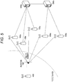
- FIGs. 5 and 6 are explanatory diagrams illustrating examples of the interference model assumed in the present embodiment.
- Fig. 5 is an explanatory diagram illustrating interference that the wireless devices 100a to 100e give to a certain protection point in a protection area of a primary system 400.
- the example of Fig. 5 is an interference model applied to a system having a service area, such as the grandfathered wireless, and considers an interference amount at a plurality of protection points set in the protection area.
- Fig. 6 illustrates an interference model applied to a system in which a primary system such as a satellite ground station performs only reception. For example, a position of a receiving antenna of the satellite ground station is used as a protection point, and an interference amount at this point is considered.
- Fig. 7 is a flowchart illustrating an operation example of a communication system according to the embodiment of the present disclosure.
- Fig. 7 illustrates an example of processing by the communication control device 300 as to whether or not to issue a frequency use permission to a wireless device 100.
- the operation example of the communication system according to the embodiment of the present disclosure will be described with reference to Fig. 7 .
- the wireless device 100 that wants to secondarily use a frequency performs a registration procedure for the communication control device 300 (step S101). During this registration procedure.
- the wireless device 100 may register device category information, installation position information, installation height information, antenna information, or the like, at least in the communication control device 300.
- the device category information may be output intensity (high output type or low output type), an emission class, or the like.
- the installation position information may be information regarding a latitude and a longitude of the wireless device 100.
- the installation height information may be information regarding a height of the wireless device 100 above the ground or above sea level.
- the antenna information may be a height, beam width, beam pattern, tilt angle, standard (boresight), gain, number of elements, antenna model, or the like of an antenna included in the wireless device 100.
- the communication control device 300 estimates a radio wave reachable range of the wireless device 100 (step S102).
- the communication control device 300 estimates the radio wave reachable range of the wireless device 100 with respect to a grid-protection area where the primary system should be protected.
- Fig. 8 is an explanatory diagram illustrating an example of the grid-protection area.
- an identifier is given to each grid of the grid-protection area.
- an n-th protection grid at a frequency f is expressed as pn(f).
- Fig. 9 is an explanatory diagram illustrating an example of a radio wave reachable range 201 of the wireless device 100 estimated by the communication control device 300.
- the communication control device 300 may estimate the radio wave reachable range 201 using predetermined reception power reference value information in addition to the registration information described above. Details of the predetermined reception power reference value information will be described later.
- a method disclosed in various documents may be used as a method of estimating the radio wave reachable range.
- WINNF-TS-0112 Version 1.3.0 "Requirements for Commercial Operation in the U.S. 3550-3700 MHz citizens Broadband Radio Service Band”
- PPA PAL Protection Area
- R2-PAL-02 The communication control device 300 may use this method.
- a reception power reference value is only required to be applied to this threshold. If there is a value specified as the reception power reference value in advance, this value may be used.
- the reception power reference value may be set by a method described later.
- Fig. 10 is an explanatory diagram illustrating an example of the bitmap recorded by the communication control device 300. That is, the communication control device 300 sets 1 for grids that overlap the radio wave reachable range 201, sets 0 for grids that do not overlap the radio wave reachable range 201, and records the grids as the bitmap.
- the communication control device 300 may record estimated powers in the grids set to 1 in the bitmap. When recording the estimated powers, the communication control device 300 may use values obtained at the time of estimating the radio wave reachable range as they are.
- the communication control device 300 performs similar processing on all wireless devices 100.
- “all” includes various meanings.
- “all” the wireless devices 100 “managed by the communication control device 300” may be meant.
- “all” the wireless devices 100 “to be subjected to the interference calculation out of the wireless devices 100 managed by the communication control device 300” may be meant. From a viewpoint of the calculation load, the latter is preferable unless there is a special reason.
- the communication control device 300 can immediately perform the processing up to step S103 after the registration procedure of the wireless device 100. Unless the registration information of the wireless device 100 changes, the communication control device 300 preferably holds obtained bitmap information or the like as much as possible.
- the wireless device 100 notifies the communication control device 300 of a frequency use request after the processing of step S103 is completed (step S104).
- the communication control device 300 uses the set bitmap information or the like to make a frequency use permission determination for the wireless device 100 that has notified the communication control device 300 of the request.
- the following two types of frequency use requests are assumed: a fixed type and a flexible type.
- the fixed type is a type that specifies a frequency band and the maximum transmission power that the wireless device 100 wants to use, and requests the communication control device 300 to permit operation based on these operation parameters.
- the flexible type is a type that specifies, to the communication control device 300, only minimum requirements regarding the operation parameters.
- the communication control device 300 specifies the operation parameters of the wireless device 100 on the basis of the minimum requirements (for example, a bandwidth and a transmission power range).
- the wireless device 100 specifies the desired maximum transmission power to the communication control device 300. Therefore, there may be a deviation from a transmission power value used at the time of estimating the radio wave reachable range. In such a case, the communication control device 300 may correct a reception power value in each grid by a difference between the transmission power value used at the time of estimation and the desired maximum transmission power to change a grid used as an edge of the radio wave reachable range.
- the communication control device 300 can be regarded as having a narrower radio wave reachable range.
- the transmission power value may deviate similarly to the fixed type if the transmission power range is specified.
- the communication control device 300 may correct the radio wave reachable range, similarly to the case of the fixed type.
- the maximum transmission power may be determined depending on a protection calculation of another primary system. Even in such a case, the communication control device 300 may correct the radio wave reachable range, similarly to the above-described case.
- the communication control device 300 makes a determination in the frequency use permission determination on the basis of cumulative interference power (aggregate interference) of the plurality of wireless devices 100 that may occur in the protection area. In this case, in a case where there is a wireless device 100 that is already using the secondary system, the communication control device 300 may make a permission determination in accordance with a frequency use permission from still another wireless device 100.
- the communication control device 300 calculates a logical sum (OR) in a bitmap set for the wireless devices 100 prior to calculation of the cumulative interference power.
- Fig. 11 is an explanatory diagram illustrating an example of the bitmap recorded by the communication control device 300. Fig. 11 illustrates an example in which radio wave reachable ranges of two wireless devices 100 are set by the bitmap.
- the communication control device 300 calculates the cumulative interference power only for grids where the logical sum is 1. The cumulative interference power is obtained by a sum of the recorded estimated reception powers (or the corrected reception powers described above).
- the communication control device 300 may calculate a logical product (AND) in the bitmap set for the wireless devices 100, and calculate the cumulative interference power only for grids where the logical product is 1.
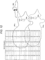
- Fig. 12 is an explanatory diagram illustrating an example of the bitmap recorded by the communication control device 300.
- Fig. 12 illustrates an example in which radio wave reachable ranges of two wireless devices 100 are set by the bitmap.
- the communication control device 300 can significantly reduce a required amount of the interference calculation in the protection area by generating the bitmap in this way and further utilizing a logical operation. Particularly in a case where the wireless device 100 uses a directional antenna, a great effect of reducing the amount of the interference calculation by the communication control device 300 is expected.
- the communication control device 300 calculates the cumulative interference power only for grids in each of which a result of the logical operation is 1, in the grid-protection area, and determines whether or not the cumulative interference power satisfies a protection reference value of the primary system (step S105). The communication control device 300 then responds with a determination result to the wireless device 100 (step S106) .
- the communication control device 300 determines that the reference is satisfied, the communication control device 300 issues a permission notification to the wireless device 100 that has notified the communication control device 300 of the request.
- the communication control device 300 encloses allowable operation parameters and notifies the wireless device 100 that has made the request.
- the communication control device 300 issues a refusal notification to the wireless device 100 that has notified the communication control device 300 of the request.
- the communication control device 300 may notify the wireless device 100 of recommended operation parameters.
- the wireless device 100 can notify the communication control device 300 of a radio wave use request again by using the recommended operation parameters.
- the communication control device 300 can significantly reduce the required amount of the interference calculation in the protection area. Meanwhile, it is necessary to satisfy interference protection requirements of the primary system. If the radio wave reachable range is not set appropriately in accordance with the interference protection requirements, the above-described method of reducing the amount of the interference calculation is meaningless. Therefore, an example of a method of setting the reception power reference value by the communication control device 300 will be shown.
- a reception power reference value for an i-th communication device is P baseRx, i (f), where f is a frequency.
- the frequency may be a value actually used by the communication device, but may be set to a specific frequency for convenience.
- a value of an allowable interference power may be the reception power reference value P baseRx, i (f). That is, the reception power reference value P baseRx, i (f) can be set as in the following expression.
- P baseRx , i f dBm I Accept f dBm
- the reception power reference value may be set as in the following expression.
- P baseRx , i f dBm I Accept f dBm ⁇ 10 log N dB In this expression.
- N expresses the number of communication devices.
- N may be the number of wireless devices 100 existing near the i-th communication device (for example, within a range of a predetermined radius value).
- the communication control device 300 may count the number of wireless devices 100 whose radio wave reachable ranges (or grids each having a bitmap of 1) at least partially overlap, and expand the radio wave reachable ranges.
- Fig. 13 is an explanatory diagram illustrating an example of a relationship between the reception power and a cumulative distribution function (CDF). As illustrated in Fig. 13 , it is necessary to determine the radio wave reachable range on the basis of the reception power at which the CDF is 0.95.
- CDF cumulative distribution function
- a reception power random variable P Rx, i P baseRx , i dBm + R dB
- R is a random variable, which is a term that reflects fluctuation due to fading or the like.
- a threshold probability is p
- CDF(R) is a CDF of the random variable R. Therefore, a conditional expression of the reception power reference value P baseRx, i (f) is calculated as follows. P baseRx , i dBm ⁇ I Th dBm ⁇ CDF ⁇ 1 p
- a right side of the above expression is not necessarily an integer, but is typically a decimal.
- the reception power value can be easily determined by use of significant digits, for example. For example, in a case where the significant digits are two digits and a calculation result on the right side is three digits or more after a decimal point, a numerical value that satisfies the number of significant digits can be calculated. For example, if the right side is -90.1214, the maximum reception power value is -90.30.
- CDF may use a theoretical expression.
- R 1 2 1 + erf R ⁇ u 2 ⁇ 2
- conditional expression for the reception power reference value P baseRx, i (f) can be expressed as follows.
- the communication control device 300 may use, for example, a CDF derived by a Monte Carlo simulation instead of the theoretical expression.
- the communication control device 300 may apply the above conditional expression by recording the CDF like a lookup table and acquiring a value of the random variable R having the threshold probability p.
- the protection area is gridded to generate the bitmap, but the present disclosure is not limited to this example.
- the bitmap may be generated by introducing a concept of a height direction to the protection area and expressing the protection area with a cube.
- the communication device may be provided with various duplex modes. For example, time division duplex (TDD), frequency division duplex (FDD), and full duplex may be provided. Furthermore, in recent years, wireless technology such as LTE and 5G NR, which are cellular systems, is being provided with listen-before-talk (LBT) that a wireless LAN is provided with, along with use of a license-exempt band. Considering these, not all communication devices are necessarily transmitting radio waves at the same time. Therefore, an embodiment in a case of considering the duplex mode will be described below.
- Information indicating access technology or information indicating an access method may be acquired as the information related to the duplex mode.
- the information indicating the access technology may be an identifier indicating LTE, Wi-Fi, 5G new radio (NR), or the like, or a release number thereof.
- the information indicating the access method may be the TDD, the full duplex, or the LBT.
- TDD configuration information, available TDD configuration information, or time information serving as a reference for synchronization between base stations may be acquired.
- category information four categories are defined in 3GPP), available category information, or the like may be acquired.
- the present embodiment does not assume that the FDD is used for communication between the wireless device 100 and the terminal 200. This is because it is extremely unlikely that the wireless device 100 and the terminal 200 emit radio waves at the same time since frequencies are different between downlink and uplink.
- the FDD is not necessarily excluded. In a case where an FDD uplink frequency of a specific terminal is the same as an FDD downlink frequency of a specific wireless device, or adjacent channel interference may be given to a system to be protected, the FDD may also be considered.
- the TDD will be focused out of the access method information.
- a similar method can be applied to other access methods.
- Fig. 14 is an explanatory diagram illustrating a configuration example of a frame applied to the FDD, for example. As illustrated in Fig. 14 , one frame has a time length of 10 milliseconds, one frame consists of 10 subframes, and one subframe consists of two slots.
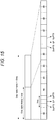
- Fig. 15 is an explanatory diagram illustrating a configuration example of a frame applied to the TDD, for example.
- Table 1 is an explanatory diagram showing setting of allocation of the uplink and the downlink in the TDD.
- the communication control device 300 can calculate overlap between coverages of terminals 200 that perform the downlink at the same time and calculate the cumulative interference power by the method based on the bitmap.
- a network manager may have a function of the communication control device of the present embodiment.
- the network manager may be a centralized base band unit (BBU) having a network configuration called centralized RAN or a device including the centralized BBU.
- BBU centralized base band unit
- a wireless base station or an access point may have a function of the network manager of the present embodiment.
- a terminal may be applied instead of the wireless system shown in the present embodiment.
- a macrocell in a heterogeneous network may be the primary system, and a small cell or a relay station may be the secondary system.
- the base station may be the primary system, and a relay UE or a vehicle UE that implements D2D or V2X existing within a coverage of the primary system may be the secondary system.
- the base station is not limited to a fixed type, but may be a portable type or a mobile type.
- frequency used in the present embodiment may be replaced with another term.
- a term an indicating frequency block such as "frequency channel”, “resource block”, or “component carrier” may be applied instead.
- FIG. 16 is an explanatory diagram illustrating the functional configuration example of the communication control device 300 according to the embodiment of the present disclosure.
- the functional configuration example of the communication control device 300 according to the embodiment of the present disclosure will be described with reference to Fig. 16 .
- the communication control device 300 includes a communication unit 310, a control unit 320, and a storage unit 330.
- the communication unit 310 executes communication with other devices under control of the control unit 320.
- the communication unit 310 transmits information for controlling the wireless device 100 managed by the communication control device 300, and transmits and receives, to and from another communication control device, information regarding a wireless device to be managed.
- the control unit 320 controls operation of the communication control device 300. Specifically, the control unit 320 performs the above-described various calculations of a margin and processing of accommodating a residual interference margin on the basis of information managed by the communication control device 300 and the information acquired by the communication unit 310.
- the control unit 320 can include, for example, a processor such as a central processing unit (CPU) and a storage device such as a read only memory (ROM) or a random access memory (RAM).
- the storage unit 330 stores information, programs, or the like for the operation of the communication control device 300.
- the storage unit 330 stores, for example, the frequency management database described above.
- the frequency management database stored in the storage unit 330 is updated by the control unit 320.
- the storage unit 330 can include various recording devices such as a hard disk drive (HDD), for example.
- the frequency management database described above may be stored in another device different from the communication control device 300. In this case, the communication control device 300 updates the frequency management database stored in the another device and refers to the frequency management database.
- the configuration of the communication control device 300 described above is for explaining the configuration for executing the function of the communication control device 300, and the communication control device 300 may have a configuration other than the configuration described above in order to execute the operation described so far.
- an acquisition unit in the present disclosure may be the communication unit 310 or may be an interface between the communication unit 310 and the control unit 320. That is, the communication unit 310 acquires a parameter for calculating a coverage of one or more second wireless systems (secondary systems) that share a part or the whole of a frequency allocated to a first wireless system (primary system).
- the control unit 320 calculates the coverage of the second wireless system on the basis of the parameter acquired by the communication unit 310, and generates information indicating whether or not a partitioned geographical range is included in the coverage.
- the control unit 320 then records a reception power level from the second wireless system in the geographical range in which the generated information satisfies a predetermined condition.
- the acquisition unit and the control unit according to the present disclosure may be implemented by one system-on-a-chip (SoC).
- SoC system-on-a-chip
- the control unit 320 may have functions of the acquisition unit and the control unit according to the present disclosure.
- the communication control device 300 may set a band use condition when causing the wireless device 100 to use a frequency of a shared band.
- the wireless device 100 that uses the shared band can use a usable band that is a part of the above shared band even if the wireless device 100 cannot use the whole of the above shared band. Therefore, use efficiency of the above shared band can be improved.
- the above band use condition includes a space in which the wireless device 100 can use the above shared band (hereinafter, "usable space").
- the above usable space is a space in which a reception power of a signal transmitted by the wireless device 100 using the above shared band may be equal to or higher than a predetermined power.
- the above usable space is any space other than a space in which the reception power of the signal transmitted by the wireless device 100 using the above shared band must be lower than the predetermined power.
- the wireless device 100 can use the above shared band in a limited space even if the above shared band cannot be used in the whole space.
- the wireless device 100 may use the above shared band with a suppressed transmission power even if the above shared band cannot be used with the maximum transmission power. Therefore, use efficiency of the above shared band can be improved.
- the above usable space is not limited to a space in which the wireless device 100 can use the whole of the above shared band, but may be a space in which the wireless device 100 can use a part of the above shared band.
- the above usable space may be an exclusive space of the wireless system for the above shared band (that is, a space in which a wireless device of another wireless system other than the wireless system cannot use a part or the whole of the above shared band).
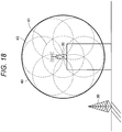
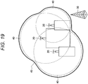
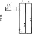
- FIGs. 17 to 23 are explanatory diagrams for describing first to seventh examples of the usable space of the wireless system.
- a wireless device 20 of a wireless system and a wireless device 30 of another wireless system are illustrated.
- the wireless device 20 is a base station of the wireless system
- the wireless device 30 is a reception device.
- a level of interference with the wireless device 30 exceeds an allowable level of the above another wireless system.
- a transmission power candidate that makes the level of interference with the wireless device 30 equal to or lower than the above allowable level is selected, and a space corresponding to the transmission power candidate (for example, a space in which a reception power of a signal transmitted by the wireless device 20 with the transmission power candidate is equal to or higher than a predetermined power) is calculated as a usable space 40.
- Use of a shared band by the wireless device 20 is then permitted under the use condition including the usable space 40.
- a space corresponding to the above maximum transmission power is calculated as the usable space 40.
- a wireless device 20 of a wireless system and a wireless device 30 of another wireless system are illustrated.
- a transmission power candidate (of the wireless device 20) that makes a level of interference with the wireless device 30 equal to or lower than the above allowable level is selected. That is, a transmission power candidate smaller than that in the example illustrated in Fig. 17 is selected.
- a usable space 40 including a space 41 in which a reception power of a signal transmitted by the wireless device 20 with the transmission power candidate is equal to or higher than a predetermined power, and a space 43 in which a signal transmitted by the above another wireless device is equal to or higher than the above predetermined power is calculated.
- a usable space 40 for each of three wireless devices 20 is calculated. Furthermore, a combined space of three usable spaces 40 is finally calculated as a usable space 45 for the above three wireless devices 20.
- the communication control device 300 may calculate the usable space 40 for each wireless device 20, and may calculate the usable space 45 for the plurality of wireless devices 20 (that is, the combined space of the plurality of usable spaces 40).
- Fig. 20 three wireless devices 20 of a wireless system and a wireless device 30 of another wireless system are illustrated.
- the wireless devices 20 perform beamforming, and usable spaces 40 for the wireless devices 20 in a case where the wireless devices 20 perform beamforming are calculated.
- a combined space of three usable spaces 40 is calculated as a usable space 45 for the above three wireless devices 20.
- a plurality of wireless devices 20 of a wireless system and a plurality of wireless devices 30 of another wireless system are illustrated.
- a space that does not overlap a space 50 in which the plurality of wireless devices 30 of the above another wireless system can use a shared band is calculated as a usable space 45 for the plurality of wireless devices 30.
- a usable space 40 for each of the plurality of wireless devices 30 may be calculated.
- a plurality of wireless devices 20 of a wireless system and a plurality of wireless devices 30 of another wireless system are illustrated.
- all spaces other than a space 50 in which the plurality of wireless devices 30 of the above another wireless system can use a shared band are calculated as usable spaces for the plurality of wireless devices 30.
- a space 50 in which the wireless device 30 can use a shared band is a space on a second basement floor.
- a space on a third floor and a fourth floor of a building is selected as a usable space 40A for a wireless device 20A
- a space on a first basement floor is selected as a usable space 40B for a wireless device 20B.
- a space on a floor can be selected as a usable space.
- the wireless devices 20 cannot radiate radio waves in a shape such as the usable spaces 40 described above (for example, the space on the third floor and the fourth floor of the building, or the space on the first basement floor). Therefore, the maximum transmission power of the wireless devices 20 may be calculated so that a leakage power to the outside of the usable spaces 40 is equal to or lower than a predetermined power (or lower than the predetermined power). Furthermore, the usable spaces 40 including a margin space outside the floors may be calculated in consideration of leakage of the radio waves outside the floors.
- a communication control device capable of efficiently calculating an interference power by reducing a calculation amount in an interference calculation in a system sharing a frequency.
- each step in the processing executed by each device in the present specification does not necessarily need to be processed in time series in the order described as a sequence diagram or a flowchart.
- each step in the processing executed by each device may be processed in an order different from the order described as the flowchart, or may be processed in parallel.
Landscapes
- Engineering & Computer Science (AREA)
- Signal Processing (AREA)
- Computer Networks & Wireless Communication (AREA)
- Quality & Reliability (AREA)
- Physics & Mathematics (AREA)
- Electromagnetism (AREA)
- Mobile Radio Communication Systems (AREA)
Abstract
Description
- The present disclosure relates to a communication control device, a communication control method, and a computer program.
- Due to a wireless environment in which various wireless systems coexist and an increase and diversification of an amount of content via wireless communication in recent years, a problem that radio wave resources (frequency) that can be allocated to a wireless system is exhausted has come to the surface. However, it has been found that it is difficult to allocate new radio wave resources because existing wireless systems have already used all radio wave bands. Therefore, in order to generate necessary radio wave resources, use and utilization of radio waves of an existing wireless system that are idle in terms of time and space (white space) by utilizing cognitive wireless technology have begun to be sought (dynamic frequency sharing (dynamic spectrum access: DSA)). In recent years, in the United States, aiming to open, to the general public, the Federal use band (3.55 to 3.70 GHz) overlapping with a frequency band that is worldwide used as
3GPP band 42, 43, legalization and standardization of citizens broadband radio service (CBRS), which utilizes frequency sharing technology, are accelerating. - Furthermore, the cognitive wireless technology contributes not only to the dynamic frequency sharing but also to improvement of a frequency use efficiency of a wireless system. For example, ETSI EN 303 387 and IEEE 802.19.1-2014 define coexistence technology of wireless systems that uses the white space. In addition, Wireless Innovation Forum (WinnForum) has established a standard, called SAS-SAS Protocol, for information exchange between a plurality of SASs, each of which is a frequency management database in CBRS, shown in Non-Patent
Document 1. - Non-Patent Document 1: "Signaling Protocols and Procedures for Citizens Broadband Radio Service (CBRS): Spectrum Access System (SAS)-SAS Interface Technical Specification", WINNF-TS-0096, Internet <URL: https://workspace.winnforum.org/higherlogic/ws/public/doc ument?document_id=4813>
- In frequency sharing, in order for cumulation of interference from a plurality of communication devices not to exceed an allowable value of interference (referred to as interference margin) of a primary system, it is important to distribute the interference margin to the communication devices and that the frequency management database controls a maximum transmission power allowed for a communication device (maximum allowable transmission power). However, if interference calculations are performed for all protection areas, a calculation amount is enormous and a calculation load of the frequency management database increases.
- Therefore, in the present disclosure, there are proposed, in a system sharing a frequency, a new and improved communication control device, communication control method, and computer program that can efficiently calculate an interference power by reducing a calculation amount in an interference calculation.
- According to the present disclosure, there is provided a communication control device including an acquisition unit that acquires a parameter for calculating a coverage of one or more second wireless systems that share a part or a whole of a frequency allocated to a first wireless system, and a control unit that calculates the coverage of the second wireless system on the basis of the parameter acquired by the acquisition unit and a predetermined reception power reference value, generates information indicating whether or not a partitioned geographical range is included in the coverage, and records a reception power level from the second wireless system in the geographical range in which the information satisfies a predetermined condition.
- Furthermore, according to the present disclosure, there is provided a communication control method including executing, by a processor, acquiring a parameter for calculating a coverage of one or more second wireless systems that share a part or a whole of a frequency allocated to a first wireless system, calculating the coverage of the second wireless system on the basis of the acquired parameter and a predetermined reception power reference value, generating information indicating whether or not a partitioned geographical range is included in the coverage, and recording a reception power level from the second wireless system in the geographical range in which the information satisfies a predetermined condition.
- Furthermore, according to the present disclosure, there is provided a computer program that causes a computer to execute acquiring a parameter for calculating a coverage of one or more second wireless systems that share a part or a whole of a frequency allocated to a first wireless system, calculating the coverage of the second wireless system on the basis of the acquired parameter and a predetermined reception power reference value, generating information indicating whether or not a partitioned geographical range is included in the coverage, and recording a reception power level from the second wireless system in the geographical range in which the information satisfies a predetermined condition.
- As described above, according to the present disclosure, it is possible to provide, in a system sharing a frequency, a new and improved communication control device, communication control method, and computer program that can efficiently calculate an interference power by reducing a calculation amount in an interference calculation.
- Note that the above effect is not necessarily limited, and any of the effects shown in the present specification or other effects that can be grasped from the present specification may be exhibited together with or in place of the above effect.
-
-
Fig. 1 is an explanatory diagram illustrating an example of allocating an interference margin to secondary systems. -
Fig. 2 is an explanatory diagram illustrating a configuration example of a wireless system according to an embodiment of the present disclosure. -
Fig. 3 is an explanatory diagram illustrating a hierarchical structure of a CBRS use. -
Fig. 4 is an explanatory diagram illustrating a CBRS band. -
Fig. 5 is an explanatory diagram illustrating an example of an interference model assumed in the present embodiment. -
Fig. 6 is an explanatory diagram illustrating an example of the interference model assumed in the present embodiment. -
Fig. 7 is a flowchart illustrating an operation example of a communication system according to the embodiment of the present disclosure. -
Fig. 8 is an explanatory diagram illustrating an example of a grid-protection area. -
Fig. 9 is an explanatory diagram illustrating an example of a radio wave reachable range of a communication device estimated by a communication control device. -
Fig. 10 is an explanatory diagram illustrating an example of a bitmap recorded by the communication control device. -
Fig. 11 is an explanatory diagram illustrating an example of the bitmap recorded by the communication control device. -
Fig. 12 is an explanatory diagram illustrating an example of the bitmap recorded by the communication control device. -
Fig. 13 is an explanatory diagram illustrating an example of a relationship between a reception power and a cumulative distribution function. -
Fig. 14 is an explanatory diagram illustrating a configuration example of a frame applied to FDD. -
Fig. 15 is an explanatory diagram illustrating a configuration example of a frame applied to TDD. -
Fig. 16 is an explanatory diagram illustrating a functional configuration example of acommunication control device 300 according to the embodiment of the present disclosure. -
Fig. 17 is an explanatory diagram for describing an example of a usable space for the wireless system. -
Fig. 18 is an explanatory diagram for describing an example of the usable space for the wireless system. -
Fig. 19 is an explanatory diagram for describing an example of the usable space for the wireless system. -
Fig. 20 is an explanatory diagram for describing an example of the usable space for the wireless system. -
Fig. 21 is an explanatory diagram for describing an example of the usable space for the wireless system. -
Fig. 22 is an explanatory diagram for describing an example of the usable space for the wireless system. -
Fig. 23 is an explanatory diagram for describing an example of the usable space for the wireless system. - Hereinafter, a preferred embodiment of the present disclosure will be described in detail with reference to the accompanying drawings. Note that, in the present specification and the drawings, components having substantially the same functional configuration are denoted by the same reference numeral, and thus redundant description will be omitted.
- Note that the description will be made in the following order.
- 1. Embodiment of Present Disclosure
- 1.1. Background
- 1.2. Overview
- 1.3. Application Example
- 1.4. Configuration Example
- 2. Summary
- Before describing the embodiment of the present disclosure in detail, a background of the embodiment of the present disclosure will be described.
- In frequency sharing, it is important to control interference from a secondary system so as not to give fatal interference to a primary system. More specifically, it is important that a frequency management database controls a plurality of communication devices so that cumulation of interference (interference aggregation) from the communication devices does not exceed an allowable value of the primary system.
- For example, ECC Report 186 and CBRS Requirements disclose that an interference tolerance of the primary system is defined as "interference margin", the interference margin is distributed to the plurality of communication devices, and whether or not secondary frequency use is possible is determined on the basis of the distributed interference margin. The distributed interference margin (interference tolerance) is used as a reference, and a maximum transmission power (maximum allowable transmission power) allowed for a communication device is calculated by a back-calculation from a propagation loss, an antenna gain, and the like, so that the interference margin can be applied to the communication devices.
-
Fig. 1 is an explanatory diagram illustrating an example of allocating the interference margin to secondary systems. When an allowable amount of interference is given, the amount is distributed to a plurality of secondary systems, and radio waves are transmitted on the basis of the distributed allowable amount of interference (that is, margin per device), so that fatal interference to the primary system can be suppressed. In the example ofFig. 1 , a method is conceivable in which the allowable amount of interference of the primary system is Iaccept, and interferences given to the primary system by the secondary systems are I1, I2, and I3, respectively, and the allowable amount of interference is allocated so that a sum of I1, I2, and I3 is equal to or less than Iaccept. However, this method may be excessive suppression depending on a propagation environment or the like, and thus WinnForum Requirement ("Requirements for Commercial Operation in theU.S. 3550-3700 - The distributed interference margin (interference tolerance) is used as a reference, a maximum transmission power (maximum allowable transmission power) allowed for a communication device is calculated by a back-calculation from a propagation loss, an antenna gain, and the like, so that the interference margin can be applied to the communication devices. In the above non-patent document, it is recommended to find an interference calculation reference point with the most severe interference (interference victim reference point) and to determine a transmission power so as to protect this point, thereby protecting the entire primary system.
- On the other hand, the non-patent document CBRS Requirements defines a method called dynamic protection area (DPA) protection in order to protect the Federal Incumbent Radar. This method requires that a predetermined protection area is divided into grids regardless of a location of the Federal Incumbent Radar, and that an interference power is estimated at each grid (protection point) so that the interference power does not exceed the allowable value.
- However, performing such interference calculations in all the grids leads to a calculation load of the frequency management database corresponding to a communication control device. Therefore, it is necessary to provide a means for more efficiently calculating the interference power for the purpose of reducing a calculation amount.
- Therefore, in view of the above-described points, the present discloser has diligently studied technology capable of efficiently calculating the interference power by reducing the calculation amount in the interference calculation in a system sharing a frequency. As a result, the present discloser has devised the technology capable of efficiently calculating the interference power by reducing the calculation amount in the interference calculation in the system sharing a frequency, as described below.
- First, a configuration example of a wireless system according to the embodiment of the present disclosure will be described.
Fig. 2 is an explanatory diagram illustrating the configuration example of the wireless system according to the embodiment of the present disclosure.Fig. 2 illustrateswireless devices 100a to 100d,terminals 200a to 200d that wirelessly communicate with the respective wireless devices, andcommunication control devices - The
wireless devices 100a to 100d are typically devices corresponding to wireless base stations, access points, or wireless relay stations. Thewireless devices 100a to 100d may be fixed or may be installed in moving objects such as automobiles. Wireless access technology used by thewireless devices 100a to 100d is not limited to a specific one. Furthermore, coverages of thewireless devices 100a to 100d may be large like macrocells or small like picocells. In addition, in a case where thewireless devices 100a to 100d have capability of beamforming, a cell or a service area may be formed for each beam. Typically, one wireless device is installed and operated by one business operator or one individual, but the present disclosure is not limited to this. Thewireless devices 100a to 100d may be shared facilities used by a plurality of business operators or a plurality of individuals. In this case, thewireless devices 100a to 100d may be installed and operated by a third party different from a user. - The
terminals 200a to 200d are typically communication equipment such as smartphones. Theterminals 200a to 200d do not necessarily have to be used by a person, and for example, devices such as factory machines and sensors installed in buildings may be network-connected. Furthermore, as represented by device to device (D2D), theterminals 200a to 200d may have a relay communication function. In addition, theterminals 200a to 200d may be devices called customer premises equipment (CPE) used in a wireless backhaul or the like. - The
communication control devices wireless devices 100a to 100d. For example, thecommunication control devices communication control devices communication control devices Fig. 3 , thecommunication control devices communication control devices communication control devices wireless devices 100a to 100d, but thecommunication control devices terminals 200a to 200d with which thewireless devices 100a to 100d perform wireless communication. - In the present embodiment, the description will be made assuming the frequency sharing environment. As an example, in the citizens broadband radio service (CBRS) legislated by the Federal Communications Commission (FCC) in the United States, the primary system is a military radar, a grandfathered wireless system, and a fixed satellite service (radio wave transmission from space to earth), and the secondary system is a wireless system called citizens broadband radio service device (CBSD), as illustrated in a figure below. The secondary system further has priority, and a priority access license (PAL) that allows license use of a shared band and a general authorized access (GAA) that is equivalent to license-free are defined. Of course, the wireless system is not limited to these when the present disclosure is implemented. Another wireless system may be the primary system. Furthermore, a frequency sharing environment in another frequency band may be used. In addition, the present disclosure is not limited to the frequency sharing. The technology of the present disclosure may be applied to a scenario of network coexistence between the same or different wireless systems that use the same frequency.
-
Fig. 3 is an explanatory diagram illustrating a hierarchical structure of a CBRS use. There are a priority access tier above a general authorized access tier and an incumbent tier above the priority access tier. Furthermore,Fig. 4 is an explanatory diagram illustrating a CBRS band. In the present embodiment, it is assumed that bands of the general authorized access tier, the priority access tier, and the incumbent tier are defined as illustrated inFig. 4 . - Next, an example of an interference model is shown.
Figs. 5 and6 are explanatory diagrams illustrating examples of the interference model assumed in the present embodiment.Fig. 5 is an explanatory diagram illustrating interference that thewireless devices 100a to 100e give to a certain protection point in a protection area of aprimary system 400. The example ofFig. 5 is an interference model applied to a system having a service area, such as the grandfathered wireless, and considers an interference amount at a plurality of protection points set in the protection area.Fig. 6 illustrates an interference model applied to a system in which a primary system such as a satellite ground station performs only reception. For example, a position of a receiving antenna of the satellite ground station is used as a protection point, and an interference amount at this point is considered. - Next, a method of reducing the calculation amount in a case of an estimation amount of interference power in a
communication control device 300 according to the embodiment of the present disclosure will be described. In the present embodiment, it is assumed that a predetermined protection area is divided into grids, the interference power is estimated in each grid, and the interference power is made not to exceed the allowable value. However, performing such interference calculations in all the grids leads to a calculation load of a frequency management database corresponding to thecommunication control device 300. Therefore, it is necessary to provide a means for more efficiently calculating the interference power for the purpose of reducing the calculation amount. -
Fig. 7 is a flowchart illustrating an operation example of a communication system according to the embodiment of the present disclosure.Fig. 7 illustrates an example of processing by thecommunication control device 300 as to whether or not to issue a frequency use permission to awireless device 100. Hereinafter, the operation example of the communication system according to the embodiment of the present disclosure will be described with reference toFig. 7 . - First, the
wireless device 100 that wants to secondarily use a frequency performs a registration procedure for the communication control device 300 (step S101). During this registration procedure. Thewireless device 100 may register device category information, installation position information, installation height information, antenna information, or the like, at least in thecommunication control device 300. The device category information may be output intensity (high output type or low output type), an emission class, or the like. The installation position information may be information regarding a latitude and a longitude of thewireless device 100. The installation height information may be information regarding a height of thewireless device 100 above the ground or above sea level. The antenna information may be a height, beam width, beam pattern, tilt angle, standard (boresight), gain, number of elements, antenna model, or the like of an antenna included in thewireless device 100. - When the
wireless device 100 is registered, thecommunication control device 300 estimates a radio wave reachable range of the wireless device 100 (step S102). In the present embodiment, thecommunication control device 300 estimates the radio wave reachable range of thewireless device 100 with respect to a grid-protection area where the primary system should be protected.Fig. 8 is an explanatory diagram illustrating an example of the grid-protection area. In the present embodiment, an identifier is given to each grid of the grid-protection area. Here, an n-th protection grid at a frequency f is expressed as pn(f). -
Fig. 9 is an explanatory diagram illustrating an example of a radio wavereachable range 201 of thewireless device 100 estimated by thecommunication control device 300. Thecommunication control device 300 may estimate the radio wavereachable range 201 using predetermined reception power reference value information in addition to the registration information described above. Details of the predetermined reception power reference value information will be described later. - A method disclosed in various documents may be used as a method of estimating the radio wave reachable range. For example, in WINNF-TS-0112 Version 1.3.0, "Requirements for Commercial Operation in the U.S. 3550-3700 MHz Citizens Broadband Radio Service Band", a method of estimating an area boundary of a PAL protection area, which is called PAL Protection Area (PPA) default contour, is provided (R2-PAL-02). The
communication control device 300 may use this method. Here, points are placed at equal intervals (for example, 200 m) in one radiation direction set every one degree from the CBSD (corresponding to a communication device), the nearest point below a threshold (-96 dBm/10 MHz) is linearly searched for, a Hamming filter is applied to a set of 360 points in total, and the output value is used as the PPA default contour. In the present embodiment, a reception power reference value is only required to be applied to this threshold. If there is a value specified as the reception power reference value in advance, this value may be used. The reception power reference value may be set by a method described later. - When the
communication control device 300 estimates the radio wave reachable range, thecommunication control device 300 identifies grids in the protection area that overlap the radio wave reachable range, and records the grids as a bitmap (step S103).Fig. 10 is an explanatory diagram illustrating an example of the bitmap recorded by thecommunication control device 300. That is, thecommunication control device 300sets 1 for grids that overlap the radio wavereachable range 201, sets 0 for grids that do not overlap the radio wavereachable range 201, and records the grids as the bitmap. - The
communication control device 300 may record estimated powers in the grids set to 1 in the bitmap. When recording the estimated powers, thecommunication control device 300 may use values obtained at the time of estimating the radio wave reachable range as they are. - The
communication control device 300 performs similar processing on allwireless devices 100. Here, "all" includes various meanings. For example, "all" thewireless devices 100 "managed by thecommunication control device 300" may be meant. Furthermore, "all" thewireless devices 100 "to be subjected to the interference calculation out of thewireless devices 100 managed by thecommunication control device 300" may be meant. From a viewpoint of the calculation load, the latter is preferable unless there is a special reason. - The
communication control device 300 can immediately perform the processing up to step S103 after the registration procedure of thewireless device 100. Unless the registration information of thewireless device 100 changes, thecommunication control device 300 preferably holds obtained bitmap information or the like as much as possible. - It is assumed that the
wireless device 100 notifies thecommunication control device 300 of a frequency use request after the processing of step S103 is completed (step S104). After receiving the request, thecommunication control device 300 uses the set bitmap information or the like to make a frequency use permission determination for thewireless device 100 that has notified thecommunication control device 300 of the request. Here, the following two types of frequency use requests are assumed: a fixed type and a flexible type. - The fixed type is a type that specifies a frequency band and the maximum transmission power that the
wireless device 100 wants to use, and requests thecommunication control device 300 to permit operation based on these operation parameters. The flexible type is a type that specifies, to thecommunication control device 300, only minimum requirements regarding the operation parameters. Thecommunication control device 300 specifies the operation parameters of thewireless device 100 on the basis of the minimum requirements (for example, a bandwidth and a transmission power range). - In a case where the
communication control device 300 is notified of the request by the fixed type, thewireless device 100 specifies the desired maximum transmission power to thecommunication control device 300. Therefore, there may be a deviation from a transmission power value used at the time of estimating the radio wave reachable range. In such a case, thecommunication control device 300 may correct a reception power value in each grid by a difference between the transmission power value used at the time of estimation and the desired maximum transmission power to change a grid used as an edge of the radio wave reachable range. For example, in a case where the reception power value at the grid used as the edge of the estimated radio wave reachable range is -90 dBm, and the difference between the transmission power value used at the time of estimation and the desired maximum transmission power is 5 dB, the reception power value of the grid is -95 dBm, and thus the grid is out of the radio wave reachable range. Therefore, thecommunication control device 300 can be regarded as having a narrower radio wave reachable range. - In a case where the communication control device is notified of the request by the flexible type, the transmission power value may deviate similarly to the fixed type if the transmission power range is specified. In such a case, the
communication control device 300 may correct the radio wave reachable range, similarly to the case of the fixed type. - Regardless of the type of request, the maximum transmission power may be determined depending on a protection calculation of another primary system. Even in such a case, the
communication control device 300 may correct the radio wave reachable range, similarly to the above-described case. - The
communication control device 300 makes a determination in the frequency use permission determination on the basis of cumulative interference power (aggregate interference) of the plurality ofwireless devices 100 that may occur in the protection area. In this case, in a case where there is awireless device 100 that is already using the secondary system, thecommunication control device 300 may make a permission determination in accordance with a frequency use permission from still anotherwireless device 100. Thecommunication control device 300 calculates a logical sum (OR) in a bitmap set for thewireless devices 100 prior to calculation of the cumulative interference power.Fig. 11 is an explanatory diagram illustrating an example of the bitmap recorded by thecommunication control device 300.Fig. 11 illustrates an example in which radio wave reachable ranges of twowireless devices 100 are set by the bitmap. Thecommunication control device 300 calculates the cumulative interference power only for grids where the logical sum is 1. The cumulative interference power is obtained by a sum of the recorded estimated reception powers (or the corrected reception powers described above). - The
communication control device 300 may calculate a logical product (AND) in the bitmap set for thewireless devices 100, and calculate the cumulative interference power only for grids where the logical product is 1.Fig. 12 is an explanatory diagram illustrating an example of the bitmap recorded by thecommunication control device 300.Fig. 12 illustrates an example in which radio wave reachable ranges of twowireless devices 100 are set by the bitmap. - The
communication control device 300 can significantly reduce a required amount of the interference calculation in the protection area by generating the bitmap in this way and further utilizing a logical operation. Particularly in a case where thewireless device 100 uses a directional antenna, a great effect of reducing the amount of the interference calculation by thecommunication control device 300 is expected. - The
communication control device 300 calculates the cumulative interference power only for grids in each of which a result of the logical operation is 1, in the grid-protection area, and determines whether or not the cumulative interference power satisfies a protection reference value of the primary system (step S105). Thecommunication control device 300 then responds with a determination result to the wireless device 100 (step S106) . - In a case where the
communication control device 300 determines that the reference is satisfied, thecommunication control device 300 issues a permission notification to thewireless device 100 that has notified thecommunication control device 300 of the request. In a case where the request is of the flexible type, thecommunication control device 300 encloses allowable operation parameters and notifies thewireless device 100 that has made the request. On the other hand, in a case where thecommunication control device 300 determines that the reference is not satisfied, thecommunication control device 300 issues a refusal notification to thewireless device 100 that has notified thecommunication control device 300 of the request. At the time of the refusal notification, thecommunication control device 300 may notify thewireless device 100 of recommended operation parameters. Thewireless device 100 can notify thecommunication control device 300 of a radio wave use request again by using the recommended operation parameters. - By the method described above, the
communication control device 300 can significantly reduce the required amount of the interference calculation in the protection area. Meanwhile, it is necessary to satisfy interference protection requirements of the primary system. If the radio wave reachable range is not set appropriately in accordance with the interference protection requirements, the above-described method of reducing the amount of the interference calculation is meaningless. Therefore, an example of a method of setting the reception power reference value by thecommunication control device 300 will be shown. - In the following description, a reception power reference value for an i-th communication device is PbaseRx, i (f), where f is a frequency. The frequency may be a value actually used by the communication device, but may be set to a specific frequency for convenience.
- In a case where the number of communication devices serving as interference sources is one, and in addition, fluctuation due to fading or the like of a propagation path is so small as to be negligible, a value of an allowable interference power may be the reception power reference value PbaseRx, i (f). That is, the reception power reference value PbaseRx, i (f) can be set as in the following expression.

- In a case of assuming cumulation of interference by a plurality of communication devices, the reception power reference value may be set as in the following expression.

- Various methods are possible for setting N. For example, N may be the number of
wireless devices 100 existing near the i-th communication device (for example, within a range of a predetermined radius value). Furthermore, for example, after calculating the radio wave reachable range by the method described above, thecommunication control device 300 may count the number ofwireless devices 100 whose radio wave reachable ranges (or grids each having a bitmap of 1) at least partially overlap, and expand the radio wave reachable ranges. - It may be necessary to consider fading due to effects of topography or the like in the interference calculation. Therefore, for example, in WINNF-TS-0112 Version 1.3.0, "Requirements for Commercial Operation in the
U.S. 3550-3700 -
Fig. 13 is an explanatory diagram illustrating an example of a relationship between the reception power and a cumulative distribution function (CDF). As illustrated inFig. 13 , it is necessary to determine the radio wave reachable range on the basis of the reception power at which the CDF is 0.95. - Here, a reception power random variable PRx, i can be expressed as follows.

- In the above expression, R is a random variable, which is a term that reflects fluctuation due to fading or the like. When a threshold probability is p, a setting expression of the reception power reference value related to the radio wave reachable range is as follows.

- Here, CDF(R) is a CDF of the random variable R. Therefore, a conditional expression of the reception power reference value PbaseRx, i (f) is calculated as follows.

- When the
communication control device 300 determines the maximum reception power value that satisfies this expression, a right side of the above expression is not necessarily an integer, but is typically a decimal. In such a case, the reception power value can be easily determined by use of significant digits, for example. For example, in a case where the significant digits are two digits and a calculation result on the right side is three digits or more after a decimal point, a numerical value that satisfies the number of significant digits can be calculated. For example, if the right side is -90.1214, the maximum reception power value is -90.30. - Here, the CDF may use a theoretical expression. For example, if the random variable R follows a lognormal distribution, the CDF is defined by the following expression.
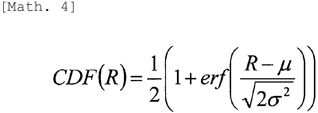
- In the above expression, erf is an error function, µ is an average, and σ is a standard deviation. In this case, the conditional expression for the reception power reference value PbaseRx, i (f) can be expressed as follows.

- Furthermore, the
communication control device 300 may use, for example, a CDF derived by a Monte Carlo simulation instead of the theoretical expression. In this case, thecommunication control device 300 may apply the above conditional expression by recording the CDF like a lookup table and acquiring a value of the random variable R having the threshold probability p. - In the example described above, the protection area is gridded to generate the bitmap, but the present disclosure is not limited to this example. For example, the bitmap may be generated by introducing a concept of a height direction to the protection area and expressing the protection area with a cube.
- The communication device may be provided with various duplex modes. For example, time division duplex (TDD), frequency division duplex (FDD), and full duplex may be provided. Furthermore, in recent years, wireless technology such as LTE and 5G NR, which are cellular systems, is being provided with listen-before-talk (LBT) that a wireless LAN is provided with, along with use of a license-exempt band. Considering these, not all communication devices are necessarily transmitting radio waves at the same time. Therefore, an embodiment in a case of considering the duplex mode will be described below.
- The description will be given on the assumption that the
communication control device 300 has acquired information related to a duplex mode of a terminal 200. A method of acquisition does not matter. Information indicating access technology or information indicating an access method may be acquired as the information related to the duplex mode. The information indicating the access technology may be an identifier indicating LTE, Wi-Fi, 5G new radio (NR), or the like, or a release number thereof. The information indicating the access method may be the TDD, the full duplex, or the LBT. In a case where the TDD is acquired as the information indicating the access method, TDD configuration information, available TDD configuration information, or time information serving as a reference for synchronization between base stations may be acquired. In a case where the LBT is acquired as the information indicating the access method, category information (four categories are defined in 3GPP), available category information, or the like may be acquired. - Note that the present embodiment does not assume that the FDD is used for communication between the
wireless device 100 and the terminal 200. This is because it is extremely unlikely that thewireless device 100 and the terminal 200 emit radio waves at the same time since frequencies are different between downlink and uplink. However, the FDD is not necessarily excluded. In a case where an FDD uplink frequency of a specific terminal is the same as an FDD downlink frequency of a specific wireless device, or adjacent channel interference may be given to a system to be protected, the FDD may also be considered. - In the following description, the TDD will be focused out of the access method information. Of course, a similar method can be applied to other access methods.
- In LTE, two types of frame configurations are supported. Furthermore, in the TDD, combinations of the uplink and the downlink are also defined, and base stations are operated in accordance with any of defined combinations.
Fig. 14 is an explanatory diagram illustrating a configuration example of a frame applied to the FDD, for example. As illustrated inFig. 14 , one frame has a time length of 10 milliseconds, one frame consists of 10 subframes, and one subframe consists of two slots. In addition,Fig. 15 is an explanatory diagram illustrating a configuration example of a frame applied to the TDD, for example. Furthermore, Table 1 is an explanatory diagram showing setting of allocation of the uplink and the downlink in the TDD. -
(Table 1: Allocation of uplink and downlink) Configuration Switch-point periodicity Subframe number 0 1 2 3 4 5 6 7 8 9 0 5 ms D S U U U D S U U U 1 5 ms D S U U D D S U U D 2 5 ms D S U D D D S U D D 3 10 ms D S U U U D D D D D 4 10 ms D S U U D D D D D D 5 10 ms D S U D D D D D D D 6 5 ms D S U U U D S U U D - As described above, in a case where the communication device is provided with the TDD, a different TDD configuration may be set for each terminal 200. Therefore, the
communication control device 300 can calculate overlap between coverages of terminals 200 that perform the downlink at the same time and calculate the cumulative interference power by the method based on the bitmap. - Although the present embodiment has been described by use of expressions such as a communication control device and a wireless system, implementation of the present disclosure is not limited to these.
- For example, it is not necessary to limit the implementation of the present disclosure to a frequency band in which the frequency sharing is performed, and in this case, a network manager may have a function of the communication control device of the present embodiment. The network manager may be a centralized base band unit (BBU) having a network configuration called centralized RAN or a device including the centralized BBU. Furthermore, a wireless base station or an access point may have a function of the network manager of the present embodiment. In this case, a "terminal" may be applied instead of the wireless system shown in the present embodiment.
- Furthermore, although, in general, an existing system that uses a target band is called the primary system and a secondary user is called the secondary system in the frequency sharing, the present disclosure may be implemented by use of other terms instead. For example, a macrocell in a heterogeneous network (HetNet) may be the primary system, and a small cell or a relay station may be the secondary system. Furthermore, the base station may be the primary system, and a relay UE or a vehicle UE that implements D2D or V2X existing within a coverage of the primary system may be the secondary system. The base station is not limited to a fixed type, but may be a portable type or a mobile type.
- Furthermore, the term "frequency" used in the present embodiment may be replaced with another term. For example, a term an indicating frequency block such as "frequency channel", "resource block", or "component carrier" may be applied instead.
- Next, a functional configuration example of the communication control device according to the embodiment of the present disclosure will be described.
Fig. 16 is an explanatory diagram illustrating the functional configuration example of thecommunication control device 300 according to the embodiment of the present disclosure. Hereinafter, the functional configuration example of thecommunication control device 300 according to the embodiment of the present disclosure will be described with reference toFig. 16 . - As illustrated in
Fig. 16 , thecommunication control device 300 according to the embodiment of the present disclosure includes acommunication unit 310, acontrol unit 320, and astorage unit 330. - The
communication unit 310 executes communication with other devices under control of thecontrol unit 320. In the present embodiment, thecommunication unit 310 transmits information for controlling thewireless device 100 managed by thecommunication control device 300, and transmits and receives, to and from another communication control device, information regarding a wireless device to be managed. - The
control unit 320 controls operation of thecommunication control device 300. Specifically, thecontrol unit 320 performs the above-described various calculations of a margin and processing of accommodating a residual interference margin on the basis of information managed by thecommunication control device 300 and the information acquired by thecommunication unit 310. Thecontrol unit 320 can include, for example, a processor such as a central processing unit (CPU) and a storage device such as a read only memory (ROM) or a random access memory (RAM). - The
storage unit 330 stores information, programs, or the like for the operation of thecommunication control device 300. Thestorage unit 330 stores, for example, the frequency management database described above. The frequency management database stored in thestorage unit 330 is updated by thecontrol unit 320. Note that thestorage unit 330 can include various recording devices such as a hard disk drive (HDD), for example. Note that the frequency management database described above may be stored in another device different from thecommunication control device 300. In this case, thecommunication control device 300 updates the frequency management database stored in the another device and refers to the frequency management database. - The configuration of the
communication control device 300 described above is for explaining the configuration for executing the function of thecommunication control device 300, and thecommunication control device 300 may have a configuration other than the configuration described above in order to execute the operation described so far. - For example, an acquisition unit in the present disclosure may be the
communication unit 310 or may be an interface between thecommunication unit 310 and thecontrol unit 320. That is, thecommunication unit 310 acquires a parameter for calculating a coverage of one or more second wireless systems (secondary systems) that share a part or the whole of a frequency allocated to a first wireless system (primary system). Thecontrol unit 320 calculates the coverage of the second wireless system on the basis of the parameter acquired by thecommunication unit 310, and generates information indicating whether or not a partitioned geographical range is included in the coverage. Thecontrol unit 320 then records a reception power level from the second wireless system in the geographical range in which the generated information satisfies a predetermined condition. - Furthermore, for example, the acquisition unit and the control unit according to the present disclosure may be implemented by one system-on-a-chip (SoC). In this case, for example, the
control unit 320 may have functions of the acquisition unit and the control unit according to the present disclosure. - The
communication control device 300 may set a band use condition when causing thewireless device 100 to use a frequency of a shared band. As a result, for example, thewireless device 100 that uses the shared band can use a usable band that is a part of the above shared band even if thewireless device 100 cannot use the whole of the above shared band. Therefore, use efficiency of the above shared band can be improved. - For example, the above band use condition includes a space in which the
wireless device 100 can use the above shared band (hereinafter, "usable space"). - For example, the above usable space is a space in which a reception power of a signal transmitted by the
wireless device 100 using the above shared band may be equal to or higher than a predetermined power. In other words, the above usable space is any space other than a space in which the reception power of the signal transmitted by thewireless device 100 using the above shared band must be lower than the predetermined power. - As a result, for example, the
wireless device 100 can use the above shared band in a limited space even if the above shared band cannot be used in the whole space. For example, thewireless device 100 may use the above shared band with a suppressed transmission power even if the above shared band cannot be used with the maximum transmission power. Therefore, use efficiency of the above shared band can be improved. - Note that the above usable space is not limited to a space in which the
wireless device 100 can use the whole of the above shared band, but may be a space in which thewireless device 100 can use a part of the above shared band. - Furthermore, the above usable space may be an exclusive space of the wireless system for the above shared band (that is, a space in which a wireless device of another wireless system other than the wireless system cannot use a part or the whole of the above shared band).
- A specific example of the usable space will be described.
Figs. 17 to 23 are explanatory diagrams for describing first to seventh examples of the usable space of the wireless system. - Referring to
Fig. 17 , awireless device 20 of a wireless system and awireless device 30 of another wireless system are illustrated. Thewireless device 20 is a base station of the wireless system, and thewireless device 30 is a reception device. In this case, for example, when thewireless device 20 transmits a signal with the maximum transmission power, a level of interference with thewireless device 30 exceeds an allowable level of the above another wireless system. Therefore, a transmission power candidate that makes the level of interference with thewireless device 30 equal to or lower than the above allowable level is selected, and a space corresponding to the transmission power candidate (for example, a space in which a reception power of a signal transmitted by thewireless device 20 with the transmission power candidate is equal to or higher than a predetermined power) is calculated as ausable space 40. Use of a shared band by thewireless device 20 is then permitted under the use condition including theusable space 40. - Note that, for example, even if the
wireless device 20 transmits a signal with the maximum transmission power, in a case where the level of interference with thewireless device 30 is equal to or lower than the allowable level of the above another wireless system, a space corresponding to the above maximum transmission power is calculated as theusable space 40. - Referring to
Fig. 18 , similarly toFig. 17 , awireless device 20 of a wireless system and awireless device 30 of another wireless system are illustrated. In this example, in consideration of presence of another wireless device (for example, a terminal device) that performs wireless communication with the wireless device 20 (for example, a base station), a transmission power candidate (of the wireless device 20) that makes a level of interference with thewireless device 30 equal to or lower than the above allowable level is selected. That is, a transmission power candidate smaller than that in the example illustrated inFig. 17 is selected. Then, for example, ausable space 40 including aspace 41 in which a reception power of a signal transmitted by thewireless device 20 with the transmission power candidate is equal to or higher than a predetermined power, and aspace 43 in which a signal transmitted by the above another wireless device is equal to or higher than the above predetermined power is calculated. - Referring to
Fig. 19 , threewireless devices 20 of a wireless system and awireless device 30 of another wireless system are illustrated. In this example, ausable space 40 for each of threewireless devices 20 is calculated. Furthermore, a combined space of threeusable spaces 40 is finally calculated as ausable space 45 for the above threewireless devices 20. - In the embodiment of the present disclosure, the
communication control device 300 may calculate theusable space 40 for eachwireless device 20, and may calculate theusable space 45 for the plurality of wireless devices 20 (that is, the combined space of the plurality of usable spaces 40). - Referring to
Fig. 20 , threewireless devices 20 of a wireless system and awireless device 30 of another wireless system are illustrated. In this example, thewireless devices 20 perform beamforming, andusable spaces 40 for thewireless devices 20 in a case where thewireless devices 20 perform beamforming are calculated. Furthermore, a combined space of threeusable spaces 40 is calculated as ausable space 45 for the above threewireless devices 20. - Referring to
Fig. 21 , a plurality ofwireless devices 20 of a wireless system and a plurality ofwireless devices 30 of another wireless system are illustrated. In this example, a space that does not overlap aspace 50 in which the plurality ofwireless devices 30 of the above another wireless system can use a shared band is calculated as ausable space 45 for the plurality ofwireless devices 30. Note that ausable space 40 for each of the plurality ofwireless devices 30 may be calculated. - Referring to
Fig. 22 , a plurality ofwireless devices 20 of a wireless system and a plurality ofwireless devices 30 of another wireless system are illustrated. In this example, all spaces other than aspace 50 in which the plurality ofwireless devices 30 of the above another wireless system can use a shared band are calculated as usable spaces for the plurality ofwireless devices 30. - Referring to
Fig. 23 , twowireless devices 20 of a wireless system and awireless device 30 of another wireless system are illustrated. In this example, aspace 50 in which thewireless device 30 can use a shared band is a space on a second basement floor. In this case, for example, a space on a third floor and a fourth floor of a building is selected as ausable space 40A for awireless device 20A, and a space on a first basement floor is selected as ausable space 40B for awireless device 20B. As described above, a space on a floor can be selected as a usable space. - Note that the
wireless devices 20 cannot radiate radio waves in a shape such as theusable spaces 40 described above (for example, the space on the third floor and the fourth floor of the building, or the space on the first basement floor). Therefore, the maximum transmission power of thewireless devices 20 may be calculated so that a leakage power to the outside of theusable spaces 40 is equal to or lower than a predetermined power (or lower than the predetermined power). Furthermore, theusable spaces 40 including a margin space outside the floors may be calculated in consideration of leakage of the radio waves outside the floors. - As described above, according to the embodiment of the present disclosure, there is provided a communication control device capable of efficiently calculating an interference power by reducing a calculation amount in an interference calculation in a system sharing a frequency.
- Each step in the processing executed by each device in the present specification does not necessarily need to be processed in time series in the order described as a sequence diagram or a flowchart. For example, each step in the processing executed by each device may be processed in an order different from the order described as the flowchart, or may be processed in parallel.
- Furthermore, it is possible to create a computer program for causing hardware such as a CPU, a ROM, and a RAM built in each device to exhibit an equivalent function to the configuration of each device described above. In addition, a storage medium storing the computer program can also be provided. Moreover, configuring each functional block illustrated in a functional block diagram with hardware makes it possible to implement a series of processing with the hardware.
- The preferred embodiment of the present disclosure has been described above in detail with reference to the accompanying drawings, but the technical scope of the present disclosure is not limited to such examples. It is obvious that those having ordinary knowledge in the technical field of the present disclosure can conceive various changes or modifications within the scope of the technical idea described in the claims, and of course, it is understood that these changes and modifications also belong to the technical scope of the present disclosure.
- Furthermore, the effects described in the present specification are merely illustrative or exemplary, and are not restrictive. That is, the technology according to the present disclosure can exhibit other effects that are obvious to those skilled in the art from the description in the present specification, in addition to or instead of the above effects.
- Note that the following configurations also belong to the technical scope of the present disclosure.
- (1) A communication control device including:
- an acquisition unit that acquires a parameter for calculating a coverage of one or more second wireless systems that share a part or a whole of a frequency allocated to a first wireless system, and
- a control unit that calculates the coverage of the second wireless system on the basis of the parameter acquired by the acquisition unit and a predetermined reception power reference value, generates information indicating whether or not a partitioned geographical range is included in the coverage, and records a reception power level from the second wireless system in the geographical range in which the information satisfies a predetermined condition.
- (2) The communication control device according to (1), in which the control unit makes a frequency use permission determination of the second wireless system by use of a predetermined requirement for the first wireless system in the geographical range in which the information satisfies the predetermined condition.
- (3) The communication control device according to (1) or (2), in which the control unit generates the information as a bitmap.
- (4) The communication control device according to (3), in which in a case where there is a plurality of devices that performs wireless communication by use of the second wireless system, the control unit takes a logical sum in the bitmap to generate the information.
- (5) The communication control device according to any of (1) to (4), in which the reception power reference value is a value set on the basis of a value of an allowable interference power of the first wireless system.
- (6) The communication control device according to any of (1) to (5), in which the reception power reference value is a value set on the basis of the number of devices that perform wireless communication by use of the second wireless system.
- (7) The communication control device according to any of (1) to (6), in which the reception power reference value is a value set on the basis of a reachable range by a maximum reception power at which a probability that an allowable interference power of the first wireless system does not exceed a threshold is greater than a predetermined value.
- (8) The communication control device according to any of (1) to (7), in which the control unit generates the information in consideration of a duplex mode of a device that performs wireless communication by use of the second wireless system.
- (9) The communication control device according to (8), in which the control unit generates the information on the basis of the number of the devices that perform downlink communication at a same time.
- (10) The communication control device according to any of (1) to (9), in which in a case where use of another one of the second wireless systems is newly requested in a state where one or more of the second wireless systems are already used, the control unit calculates a coverage of the another one of the second wireless systems.
- (11) A communication control method including executing, by a processor,
acquiring a parameter for calculating a coverage of one or more second wireless systems that share a part or a whole of a frequency allocated to a first wireless system,
calculating the coverage of the second wireless system on the basis of the acquired parameter and a predetermined reception power reference value,
generating information indicating whether or not a partitioned geographical range is included in the coverage, and
recording a reception power level from the second wireless system in the geographical range in which the information satisfies a predetermined condition. - (12) A computer program that causes a computer to execute
acquiring a parameter for calculating a coverage of one or more second wireless systems that share a part or a whole of a frequency allocated to a first wireless system,
calculating the coverage of the second wireless system on the basis of the acquired parameter and a predetermined reception power reference value,
generating information indicating whether or not a partitioned geographical range is included in the coverage, and
recording a reception power level from the second wireless system in the geographical range in which the information satisfies a predetermined condition. -
- 100a Wireless device
- 100b Wireless device
- 100c Wireless device
- 100d Wireless device
- 100e Wireless device
- 200a Terminal
- 200b Terminal
- 200c Terminal
- 200d Terminal
- 300a Communication control device
- 300b Communication control device
Claims (12)
- A communication control device comprising:an acquisition unit that acquires a parameter for calculating a coverage of one or more second wireless systems that share a part or a whole of a frequency allocated to a first wireless system; anda control unit that calculates the coverage of the second wireless system on a basis of the parameter acquired by the acquisition unit and a predetermined reception power reference value, generates information indicating whether or not a partitioned geographical range is included in the coverage, and records a reception power level from the second wireless system in the geographical range in which the information satisfies a predetermined condition.
- The communication control device according to claim 1, wherein the control unit makes a frequency use permission determination of the second wireless system by use of a predetermined requirement for the first wireless system in the geographical range in which the information satisfies the predetermined condition.
- The communication control device according to claim 1, wherein the control unit generates the information as a bitmap.
- The communication control device according to claim 3, wherein in a case where there is a plurality of devices that performs wireless communication by use of the second wireless system, the control unit takes a logical sum in the bitmap to generate the information.
- The communication control device according to claim 1, wherein the reception power reference value is a value set on a basis of a value of an allowable interference power of the first wireless system.
- The communication control device according to claim 1, wherein the reception power reference value is a value set on a basis of the number of devices that perform wireless communication by use of the second wireless system.
- The communication control device according to claim 1, wherein the reception power reference value is a value set on a basis of a reachable range by a maximum reception power at which a probability that an allowable interference power of the first wireless system does not exceed a threshold is greater than a predetermined value.
- The communication control device according to claim 1, wherein the control unit generates the information in consideration of a duplex mode of a device that performs wireless communication by use of the second wireless system.
- The communication control device according to claim 8, wherein the control unit generates the information on a basis of the number of the devices that perform downlink communication at a same time.
- The communication control device according to claim 1, wherein in a case where use of another one of the second wireless systems is newly requested in a state where one or more of the second wireless systems are already used, the control unit calculates a coverage of the another one of the second wireless systems.
- A communication control method comprising executing, by a processor:acquiring a parameter for calculating a coverage of one or more second wireless systems that share a part or a whole of a frequency allocated to a first wireless system;calculating the coverage of the second wireless system on a basis of the acquired parameter and a predetermined reception power reference value;generating information indicating whether or not a partitioned geographical range is included in the coverage; andrecording a reception power level from the second wireless system in the geographical range in which the information satisfies a predetermined condition.
- A computer program that causes a computer to execute:acquiring a parameter for calculating a coverage of one or more second wireless systems that share a part or a whole of a frequency allocated to a first wireless system;calculating the coverage of the second wireless system on a basis of the acquired parameter and a predetermined reception power reference value;generating information indicating whether or not a partitioned geographical range is included in the coverage; andrecording a reception power level from the second wireless system in the geographical range in which the information satisfies a predetermined condition.
Applications Claiming Priority (2)
| Application Number | Priority Date | Filing Date | Title |
|---|---|---|---|
| JP2018103310 | 2018-05-30 | ||
| PCT/JP2019/012165 WO2019230156A1 (en) | 2018-05-30 | 2019-03-22 | Communication control device, communication control method, and computer program |
Publications (3)
| Publication Number | Publication Date |
|---|---|
| EP3806519A1 true EP3806519A1 (en) | 2021-04-14 |
| EP3806519A4 EP3806519A4 (en) | 2021-08-11 |
| EP3806519B1 EP3806519B1 (en) | 2023-08-02 |
Family
ID=68698023
Family Applications (1)
| Application Number | Title | Priority Date | Filing Date |
|---|---|---|---|
| EP19810904.3A Active EP3806519B1 (en) | 2018-05-30 | 2019-03-22 | Communication control device, communication control method, and computer program |
Country Status (5)
| Country | Link |
|---|---|
| US (1) | US11516679B2 (en) |
| EP (1) | EP3806519B1 (en) |
| JP (1) | JP7243719B2 (en) |
| CA (1) | CA3102058A1 (en) |
| WO (1) | WO2019230156A1 (en) |
Families Citing this family (8)
| Publication number | Priority date | Publication date | Assignee | Title |
|---|---|---|---|---|
| US12127272B2 (en) * | 2019-06-12 | 2024-10-22 | Lg Electronics Inc. | Method for transmitting signal in wireless communication system |
| US11423610B2 (en) * | 2019-11-26 | 2022-08-23 | Applied Research Associates, Inc. | Large-scale environment-modeling with geometric optimization |
| JP7396318B2 (en) * | 2019-12-24 | 2023-12-12 | ソニーグループ株式会社 | Communication control device and communication control method |
| EP4084521A4 (en) * | 2019-12-24 | 2023-06-21 | Sony Group Corporation | COMMUNICATION CONTROL DEVICE AND COMMUNICATION CONTROL METHOD |
| JP7431043B2 (en) * | 2020-01-17 | 2024-02-14 | パナソニックホールディングス株式会社 | Wireless communication system, information processing device, wireless communication method, and program |
| EP4187956A4 (en) | 2020-07-21 | 2023-12-20 | Sony Group Corporation | COMMUNICATION CONTROL DEVICE AND METHOD |
| JP7537609B2 (en) * | 2021-05-18 | 2024-08-21 | 富士通株式会社 | Information processing program, information processing method, and information processing device |
| US20250212006A1 (en) * | 2022-03-25 | 2025-06-26 | Sony Group Corporation | Communication control apparatus, communication control method, and computer program |
Family Cites Families (11)
| Publication number | Priority date | Publication date | Assignee | Title |
|---|---|---|---|---|
| JP5796325B2 (en) * | 2011-03-31 | 2015-10-21 | ソニー株式会社 | COMMUNICATION CONTROL DEVICE, COMMUNICATION CONTROL METHOD, AND COMMUNICATION CONTROL SYSTEM |
| JP6007480B2 (en) | 2011-09-16 | 2016-10-12 | ソニー株式会社 | COMMUNICATION CONTROL DEVICE, COMMUNICATION CONTROL METHOD, AND COMMUNICATION CONTROL SYSTEM |
| WO2013104413A1 (en) | 2012-01-10 | 2013-07-18 | Nokia Siemens Networks Oy | Providing a radio bearer on a plurality of component carriers |
| WO2013161280A1 (en) | 2012-04-24 | 2013-10-31 | 日本電気株式会社 | Frequency management device and frequency management method for wireless system |
| WO2014031597A1 (en) * | 2012-08-24 | 2014-02-27 | Oceus Networks Inc. | Mobile cellular networks |
| WO2014199497A1 (en) | 2013-06-13 | 2014-12-18 | 富士通株式会社 | Use management device and use management method |
| CN105453628B (en) * | 2013-08-21 | 2020-09-04 | 索尼公司 | Communication control device and wireless communication device |
| US9813914B2 (en) * | 2013-12-06 | 2017-11-07 | Qualcomm Incorporated | System and method for management of spectrum interference rights and secondary use permissions |
| JP7001054B2 (en) | 2016-07-27 | 2022-01-19 | ソニーグループ株式会社 | Communication control device, wireless communication device, method and program |
| JP6988814B2 (en) * | 2016-10-20 | 2022-01-05 | ソニーグループ株式会社 | Communication control device, communication control method and computer program |
| US20190322367A1 (en) * | 2018-04-23 | 2019-10-24 | Lear Corporation | Method of controlling an unmanned aerial road side unit drone |
-
2019
- 2019-03-22 US US17/047,390 patent/US11516679B2/en active Active
- 2019-03-22 WO PCT/JP2019/012165 patent/WO2019230156A1/en not_active Ceased
- 2019-03-22 EP EP19810904.3A patent/EP3806519B1/en active Active
- 2019-03-22 JP JP2020521739A patent/JP7243719B2/en active Active
- 2019-03-22 CA CA3102058A patent/CA3102058A1/en active Pending
Also Published As
| Publication number | Publication date |
|---|---|
| EP3806519A4 (en) | 2021-08-11 |
| US11516679B2 (en) | 2022-11-29 |
| US20210120433A1 (en) | 2021-04-22 |
| CA3102058A1 (en) | 2019-12-05 |
| WO2019230156A1 (en) | 2019-12-05 |
| EP3806519B1 (en) | 2023-08-02 |
| JP7243719B2 (en) | 2023-03-22 |
| JPWO2019230156A1 (en) | 2021-07-15 |
Similar Documents
| Publication | Publication Date | Title |
|---|---|---|
| EP3806519B1 (en) | Communication control device, communication control method, and computer program | |
| EP3552422B1 (en) | Method and apparatus for handling interference connection types in citizens broadband radio service devices band | |
| US10405200B2 (en) | Transmission power determination method, communication device and program | |
| US20250351091A1 (en) | Communication control device and communication control method | |
| US8265684B2 (en) | Transmission power control method, communication device and program | |
| US11388611B2 (en) | Communication control apparatus and communication control method | |
| EP3806553B1 (en) | Wireless device, terminal, method, and computer program | |
| JP7409533B2 (en) | Communication control device, communication control method and computer program | |
| US12376044B2 (en) | Communication control method and communication control device | |
| US11290892B2 (en) | Communication control device, method and computer program product with interference margin acceptance control | |
| Mishra et al. | Outage and energy efficiency analysis for cognitive based heterogeneous cellular networks | |
| EP4203536A1 (en) | Communication control device and communication control method | |
| Carciofi et al. | Study of coexistence between different services in novel 5G Frequency Bands | |
| Park et al. | Impact of 5G New Radio Downlink Signal on Fixed-Satellite Service Earth Station | |
| Lyubchenko et al. | SEAMCAT modeling system-level EMC analysis | |
| Gepko et al. | The assessment of the aggregate eirp of user equipment operating in the LTE cell | |
| WO2026058721A1 (en) | Communication control device, communication control method, and communication control system | |
| Alam et al. | Dynamic spectrum access based on cognitive radio within cellular networks |
Legal Events
| Date | Code | Title | Description |
|---|---|---|---|
| STAA | Information on the status of an ep patent application or granted ep patent |
Free format text: STATUS: THE INTERNATIONAL PUBLICATION HAS BEEN MADE |
|
| PUAI | Public reference made under article 153(3) epc to a published international application that has entered the european phase |
Free format text: ORIGINAL CODE: 0009012 |
|
| STAA | Information on the status of an ep patent application or granted ep patent |
Free format text: STATUS: REQUEST FOR EXAMINATION WAS MADE |
|
| 17P | Request for examination filed |
Effective date: 20201123 |
|
| AK | Designated contracting states |
Kind code of ref document: A1 Designated state(s): AL AT BE BG CH CY CZ DE DK EE ES FI FR GB GR HR HU IE IS IT LI LT LU LV MC MK MT NL NO PL PT RO RS SE SI SK SM TR |
|
| AX | Request for extension of the european patent |
Extension state: BA ME |
|
| REG | Reference to a national code |
Ref country code: DE Ref legal event code: R079 Free format text: PREVIOUS MAIN CLASS: H04W0016140000 Ipc: H04W0016220000 Ref country code: DE Ref legal event code: R079 Ref document number: 602019034182 Country of ref document: DE Free format text: PREVIOUS MAIN CLASS: H04W0016140000 Ipc: H04W0016220000 |
|
| RAP3 | Party data changed (applicant data changed or rights of an application transferred) |
Owner name: SONY GROUP CORPORATION |
|
| A4 | Supplementary search report drawn up and despatched |
Effective date: 20210713 |
|
| RIC1 | Information provided on ipc code assigned before grant |
Ipc: H04W 16/22 20090101AFI20210707BHEP Ipc: H04W 16/14 20090101ALI20210707BHEP Ipc: H04B 17/318 20150101ALI20210707BHEP Ipc: H04W 16/18 20090101ALI20210707BHEP |
|
| DAV | Request for validation of the european patent (deleted) | ||
| DAX | Request for extension of the european patent (deleted) | ||
| GRAP | Despatch of communication of intention to grant a patent |
Free format text: ORIGINAL CODE: EPIDOSNIGR1 |
|
| STAA | Information on the status of an ep patent application or granted ep patent |
Free format text: STATUS: GRANT OF PATENT IS INTENDED |
|
| INTG | Intention to grant announced |
Effective date: 20230227 |
|
| GRAS | Grant fee paid |
Free format text: ORIGINAL CODE: EPIDOSNIGR3 |
|
| GRAA | (expected) grant |
Free format text: ORIGINAL CODE: 0009210 |
|
| STAA | Information on the status of an ep patent application or granted ep patent |
Free format text: STATUS: THE PATENT HAS BEEN GRANTED |
|
| AK | Designated contracting states |
Kind code of ref document: B1 Designated state(s): AL AT BE BG CH CY CZ DE DK EE ES FI FR GB GR HR HU IE IS IT LI LT LU LV MC MK MT NL NO PL PT RO RS SE SI SK SM TR |
|
| REG | Reference to a national code |
Ref country code: GB Ref legal event code: FG4D |
|
| REG | Reference to a national code |
Ref country code: CH Ref legal event code: EP |
|
| REG | Reference to a national code |
Ref country code: DE Ref legal event code: R096 Ref document number: 602019034182 Country of ref document: DE |
|
| REG | Reference to a national code |
Ref country code: IE Ref legal event code: FG4D |
|
| REG | Reference to a national code |
Ref country code: NL Ref legal event code: FP |
|
| REG | Reference to a national code |
Ref country code: LT Ref legal event code: MG9D |
|
| REG | Reference to a national code |
Ref country code: AT Ref legal event code: MK05 Ref document number: 1596222 Country of ref document: AT Kind code of ref document: T Effective date: 20230802 |
|
| PG25 | Lapsed in a contracting state [announced via postgrant information from national office to epo] |
Ref country code: GR Free format text: LAPSE BECAUSE OF FAILURE TO SUBMIT A TRANSLATION OF THE DESCRIPTION OR TO PAY THE FEE WITHIN THE PRESCRIBED TIME-LIMIT Effective date: 20231103 |
|
| PG25 | Lapsed in a contracting state [announced via postgrant information from national office to epo] |
Ref country code: IS Free format text: LAPSE BECAUSE OF FAILURE TO SUBMIT A TRANSLATION OF THE DESCRIPTION OR TO PAY THE FEE WITHIN THE PRESCRIBED TIME-LIMIT Effective date: 20231202 |
|
| PG25 | Lapsed in a contracting state [announced via postgrant information from national office to epo] |
Ref country code: SE Free format text: LAPSE BECAUSE OF FAILURE TO SUBMIT A TRANSLATION OF THE DESCRIPTION OR TO PAY THE FEE WITHIN THE PRESCRIBED TIME-LIMIT Effective date: 20230802 Ref country code: RS Free format text: LAPSE BECAUSE OF FAILURE TO SUBMIT A TRANSLATION OF THE DESCRIPTION OR TO PAY THE FEE WITHIN THE PRESCRIBED TIME-LIMIT Effective date: 20230802 Ref country code: PT Free format text: LAPSE BECAUSE OF FAILURE TO SUBMIT A TRANSLATION OF THE DESCRIPTION OR TO PAY THE FEE WITHIN THE PRESCRIBED TIME-LIMIT Effective date: 20231204 Ref country code: NO Free format text: LAPSE BECAUSE OF FAILURE TO SUBMIT A TRANSLATION OF THE DESCRIPTION OR TO PAY THE FEE WITHIN THE PRESCRIBED TIME-LIMIT Effective date: 20231102 Ref country code: LV Free format text: LAPSE BECAUSE OF FAILURE TO SUBMIT A TRANSLATION OF THE DESCRIPTION OR TO PAY THE FEE WITHIN THE PRESCRIBED TIME-LIMIT Effective date: 20230802 Ref country code: LT Free format text: LAPSE BECAUSE OF FAILURE TO SUBMIT A TRANSLATION OF THE DESCRIPTION OR TO PAY THE FEE WITHIN THE PRESCRIBED TIME-LIMIT Effective date: 20230802 Ref country code: IS Free format text: LAPSE BECAUSE OF FAILURE TO SUBMIT A TRANSLATION OF THE DESCRIPTION OR TO PAY THE FEE WITHIN THE PRESCRIBED TIME-LIMIT Effective date: 20231202 Ref country code: HR Free format text: LAPSE BECAUSE OF FAILURE TO SUBMIT A TRANSLATION OF THE DESCRIPTION OR TO PAY THE FEE WITHIN THE PRESCRIBED TIME-LIMIT Effective date: 20230802 Ref country code: GR Free format text: LAPSE BECAUSE OF FAILURE TO SUBMIT A TRANSLATION OF THE DESCRIPTION OR TO PAY THE FEE WITHIN THE PRESCRIBED TIME-LIMIT Effective date: 20231103 Ref country code: FI Free format text: LAPSE BECAUSE OF FAILURE TO SUBMIT A TRANSLATION OF THE DESCRIPTION OR TO PAY THE FEE WITHIN THE PRESCRIBED TIME-LIMIT Effective date: 20230802 Ref country code: AT Free format text: LAPSE BECAUSE OF FAILURE TO SUBMIT A TRANSLATION OF THE DESCRIPTION OR TO PAY THE FEE WITHIN THE PRESCRIBED TIME-LIMIT Effective date: 20230802 |
|
| PG25 | Lapsed in a contracting state [announced via postgrant information from national office to epo] |
Ref country code: PL Free format text: LAPSE BECAUSE OF FAILURE TO SUBMIT A TRANSLATION OF THE DESCRIPTION OR TO PAY THE FEE WITHIN THE PRESCRIBED TIME-LIMIT Effective date: 20230802 |
|
| PG25 | Lapsed in a contracting state [announced via postgrant information from national office to epo] |
Ref country code: ES Free format text: LAPSE BECAUSE OF FAILURE TO SUBMIT A TRANSLATION OF THE DESCRIPTION OR TO PAY THE FEE WITHIN THE PRESCRIBED TIME-LIMIT Effective date: 20230802 |
|
| PG25 | Lapsed in a contracting state [announced via postgrant information from national office to epo] |
Ref country code: SM Free format text: LAPSE BECAUSE OF FAILURE TO SUBMIT A TRANSLATION OF THE DESCRIPTION OR TO PAY THE FEE WITHIN THE PRESCRIBED TIME-LIMIT Effective date: 20230802 Ref country code: RO Free format text: LAPSE BECAUSE OF FAILURE TO SUBMIT A TRANSLATION OF THE DESCRIPTION OR TO PAY THE FEE WITHIN THE PRESCRIBED TIME-LIMIT Effective date: 20230802 Ref country code: ES Free format text: LAPSE BECAUSE OF FAILURE TO SUBMIT A TRANSLATION OF THE DESCRIPTION OR TO PAY THE FEE WITHIN THE PRESCRIBED TIME-LIMIT Effective date: 20230802 Ref country code: EE Free format text: LAPSE BECAUSE OF FAILURE TO SUBMIT A TRANSLATION OF THE DESCRIPTION OR TO PAY THE FEE WITHIN THE PRESCRIBED TIME-LIMIT Effective date: 20230802 Ref country code: DK Free format text: LAPSE BECAUSE OF FAILURE TO SUBMIT A TRANSLATION OF THE DESCRIPTION OR TO PAY THE FEE WITHIN THE PRESCRIBED TIME-LIMIT Effective date: 20230802 Ref country code: CZ Free format text: LAPSE BECAUSE OF FAILURE TO SUBMIT A TRANSLATION OF THE DESCRIPTION OR TO PAY THE FEE WITHIN THE PRESCRIBED TIME-LIMIT Effective date: 20230802 Ref country code: SK Free format text: LAPSE BECAUSE OF FAILURE TO SUBMIT A TRANSLATION OF THE DESCRIPTION OR TO PAY THE FEE WITHIN THE PRESCRIBED TIME-LIMIT Effective date: 20230802 |
|
| REG | Reference to a national code |
Ref country code: DE Ref legal event code: R097 Ref document number: 602019034182 Country of ref document: DE |
|
| PG25 | Lapsed in a contracting state [announced via postgrant information from national office to epo] |
Ref country code: IT Free format text: LAPSE BECAUSE OF FAILURE TO SUBMIT A TRANSLATION OF THE DESCRIPTION OR TO PAY THE FEE WITHIN THE PRESCRIBED TIME-LIMIT Effective date: 20230802 |
|
| PLBE | No opposition filed within time limit |
Free format text: ORIGINAL CODE: 0009261 |
|
| STAA | Information on the status of an ep patent application or granted ep patent |
Free format text: STATUS: NO OPPOSITION FILED WITHIN TIME LIMIT |
|
| 26N | No opposition filed |
Effective date: 20240503 |
|
| PG25 | Lapsed in a contracting state [announced via postgrant information from national office to epo] |
Ref country code: SI Free format text: LAPSE BECAUSE OF FAILURE TO SUBMIT A TRANSLATION OF THE DESCRIPTION OR TO PAY THE FEE WITHIN THE PRESCRIBED TIME-LIMIT Effective date: 20230802 |
|
| REG | Reference to a national code |
Ref country code: CH Ref legal event code: PL |
|
| PG25 | Lapsed in a contracting state [announced via postgrant information from national office to epo] |
Ref country code: BG Free format text: LAPSE BECAUSE OF FAILURE TO SUBMIT A TRANSLATION OF THE DESCRIPTION OR TO PAY THE FEE WITHIN THE PRESCRIBED TIME-LIMIT Effective date: 20230802 |
|
| PG25 | Lapsed in a contracting state [announced via postgrant information from national office to epo] |
Ref country code: LU Free format text: LAPSE BECAUSE OF NON-PAYMENT OF DUE FEES Effective date: 20240322 |
|
| PG25 | Lapsed in a contracting state [announced via postgrant information from national office to epo] |
Ref country code: MC Free format text: LAPSE BECAUSE OF FAILURE TO SUBMIT A TRANSLATION OF THE DESCRIPTION OR TO PAY THE FEE WITHIN THE PRESCRIBED TIME-LIMIT Effective date: 20230802 |
|
| PG25 | Lapsed in a contracting state [announced via postgrant information from national office to epo] |
Ref country code: MC Free format text: LAPSE BECAUSE OF FAILURE TO SUBMIT A TRANSLATION OF THE DESCRIPTION OR TO PAY THE FEE WITHIN THE PRESCRIBED TIME-LIMIT Effective date: 20230802 Ref country code: LU Free format text: LAPSE BECAUSE OF NON-PAYMENT OF DUE FEES Effective date: 20240322 Ref country code: BG Free format text: LAPSE BECAUSE OF FAILURE TO SUBMIT A TRANSLATION OF THE DESCRIPTION OR TO PAY THE FEE WITHIN THE PRESCRIBED TIME-LIMIT Effective date: 20230802 |
|
| REG | Reference to a national code |
Ref country code: BE Ref legal event code: MM Effective date: 20240331 |
|
| PG25 | Lapsed in a contracting state [announced via postgrant information from national office to epo] |
Ref country code: BE Free format text: LAPSE BECAUSE OF NON-PAYMENT OF DUE FEES Effective date: 20240331 |
|
| PG25 | Lapsed in a contracting state [announced via postgrant information from national office to epo] |
Ref country code: FR Free format text: LAPSE BECAUSE OF NON-PAYMENT OF DUE FEES Effective date: 20240331 |
|
| PG25 | Lapsed in a contracting state [announced via postgrant information from national office to epo] |
Ref country code: IE Free format text: LAPSE BECAUSE OF NON-PAYMENT OF DUE FEES Effective date: 20240322 |
|
| PG25 | Lapsed in a contracting state [announced via postgrant information from national office to epo] |
Ref country code: IE Free format text: LAPSE BECAUSE OF NON-PAYMENT OF DUE FEES Effective date: 20240322 Ref country code: FR Free format text: LAPSE BECAUSE OF NON-PAYMENT OF DUE FEES Effective date: 20240331 Ref country code: BE Free format text: LAPSE BECAUSE OF NON-PAYMENT OF DUE FEES Effective date: 20240331 Ref country code: CH Free format text: LAPSE BECAUSE OF NON-PAYMENT OF DUE FEES Effective date: 20240331 |
|
| PGFP | Annual fee paid to national office [announced via postgrant information from national office to epo] |
Ref country code: NL Payment date: 20250219 Year of fee payment: 7 |
|
| PGFP | Annual fee paid to national office [announced via postgrant information from national office to epo] |
Ref country code: DE Payment date: 20250218 Year of fee payment: 7 |
|
| PGFP | Annual fee paid to national office [announced via postgrant information from national office to epo] |
Ref country code: GB Payment date: 20250221 Year of fee payment: 7 |
|
| PG25 | Lapsed in a contracting state [announced via postgrant information from national office to epo] |
Ref country code: CY Free format text: LAPSE BECAUSE OF FAILURE TO SUBMIT A TRANSLATION OF THE DESCRIPTION OR TO PAY THE FEE WITHIN THE PRESCRIBED TIME-LIMIT; INVALID AB INITIO Effective date: 20190322 |
|
| PG25 | Lapsed in a contracting state [announced via postgrant information from national office to epo] |
Ref country code: HU Free format text: LAPSE BECAUSE OF FAILURE TO SUBMIT A TRANSLATION OF THE DESCRIPTION OR TO PAY THE FEE WITHIN THE PRESCRIBED TIME-LIMIT; INVALID AB INITIO Effective date: 20190322 |
|
| PG25 | Lapsed in a contracting state [announced via postgrant information from national office to epo] |
Ref country code: TR Free format text: LAPSE BECAUSE OF FAILURE TO SUBMIT A TRANSLATION OF THE DESCRIPTION OR TO PAY THE FEE WITHIN THE PRESCRIBED TIME-LIMIT Effective date: 20230802 |