EP3806481A1 - Equipment management device using touch panel, and method for generating management screen - Google Patents
Equipment management device using touch panel, and method for generating management screen Download PDFInfo
- Publication number
- EP3806481A1 EP3806481A1 EP18920907.5A EP18920907A EP3806481A1 EP 3806481 A1 EP3806481 A1 EP 3806481A1 EP 18920907 A EP18920907 A EP 18920907A EP 3806481 A1 EP3806481 A1 EP 3806481A1
- Authority
- EP
- European Patent Office
- Prior art keywords
- displayed
- information
- air
- area
- volume
- Prior art date
- Legal status (The legal status is an assumption and is not a legal conclusion. Google has not performed a legal analysis and makes no representation as to the accuracy of the status listed.)
- Granted
Links
Images



Classifications
-
- G—PHYSICS
- G08—SIGNALLING
- G08C—TRANSMISSION SYSTEMS FOR MEASURED VALUES, CONTROL OR SIMILAR SIGNALS
- G08C17/00—Arrangements for transmitting signals characterised by the use of a wireless electrical link
- G08C17/02—Arrangements for transmitting signals characterised by the use of a wireless electrical link using a radio link
-
- F—MECHANICAL ENGINEERING; LIGHTING; HEATING; WEAPONS; BLASTING
- F24—HEATING; RANGES; VENTILATING
- F24F—AIR-CONDITIONING; AIR-HUMIDIFICATION; VENTILATION; USE OF AIR CURRENTS FOR SCREENING
- F24F11/00—Control or safety arrangements
- F24F11/50—Control or safety arrangements characterised by user interfaces or communication
- F24F11/52—Indication arrangements, e.g. displays
-
- H—ELECTRICITY
- H04—ELECTRIC COMMUNICATION TECHNIQUE
- H04Q—SELECTING
- H04Q9/00—Arrangements in telecontrol or telemetry systems for selectively calling a substation from a main station, in which substation desired apparatus is selected for applying a control signal thereto or for obtaining measured values therefrom
-
- G—PHYSICS
- G08—SIGNALLING
- G08C—TRANSMISSION SYSTEMS FOR MEASURED VALUES, CONTROL OR SIMILAR SIGNALS
- G08C2201/00—Transmission systems of control signals via wireless link
- G08C2201/30—User interface
-
- G—PHYSICS
- G08—SIGNALLING
- G08C—TRANSMISSION SYSTEMS FOR MEASURED VALUES, CONTROL OR SIMILAR SIGNALS
- G08C2201/00—Transmission systems of control signals via wireless link
- G08C2201/90—Additional features
- G08C2201/93—Remote control using other portable devices, e.g. mobile phone, PDA, laptop
-
- H—ELECTRICITY
- H04—ELECTRIC COMMUNICATION TECHNIQUE
- H04M—TELEPHONIC COMMUNICATION
- H04M11/00—Telephonic communication systems specially adapted for combination with other electrical systems
- H04M11/007—Telephonic communication systems specially adapted for combination with other electrical systems with remote control systems
-
- H—ELECTRICITY
- H04—ELECTRIC COMMUNICATION TECHNIQUE
- H04Q—SELECTING
- H04Q2209/00—Arrangements in telecontrol or telemetry systems
- H04Q2209/40—Arrangements in telecontrol or telemetry systems using a wireless architecture
Definitions
- Embodiments of the present invention relate to a facility management apparatus using a touch panel and to a management-window generation method.
- a working condition of an air conditioner is controlled by a user using a remote controller that is communicably connected.
- a remote controller of an air conditioner control buttons for controlling a working condition concerning each function of the air conditioner and a display unit for displaying a working condition or the like concerning each function are provided separately from each other.
- the user visually perceives a change in displayed information displayed on the display unit, about a working condition concerning a corresponding function, thereby recognizing that his operation has been normally accepted.
- Patent Literature 1 JP No. 5646797 B2
- a capacitive touch panel or the like is used in many cases.
- positions of pieces of displayed information indicating working conditions are set as control buttons for the functions.
- a user can easily change a working condition concerning each of the functions by a touch operation on a position where the working condition is displayed on the touch panel.
- one possible solution is to increase the size of displayed information about a working condition to such a degree that a part of the displayed information extends off a user's finger during a touch operation.
- This solution may allow the user to recognize a change in displayed information, but cannot ensure it.
- it is difficult to enormously increase the size of displayed information about all functions.
- the invention has been made in view of the above-described situations, it is an object to provide a facility management apparatus and a management-window generation method that allow a user to visually perceive a change that is made in a working condition of the facility equipment by his operation on a touch panel in controlling the working condition.
- a remote controller of an air conditioner includes a displayed-information generation unit, a touch panel, an operation determination unit, and a working-control information generation unit.
- the displayed-information generation unit generates displayed information in which a first area that displays graphic information indicating a current working condition of facility equipment and a second area that displays text information indicating the working condition, are arranged and displayed. Then, when an operation of changing the working condition is performed, the displayed-information generation unit changes the graphic information and the text information based on a post-change working condition.
- the touch panel displays the generated displayed information. When an operation is performed on any position in the first area or the second area that are displayed, the touch panel inputs operation information corresponding to the operation.
- the operation determination unit determines an operation based on the input operation information.
- the working-control information generation unit generates working-control information for changing a working condition of the facility equipment based on the determined operation.
- An air conditioning system 1 includes a plurality of air conditioners (indoor units) 10-1 to 10-100 that are installed in a 10-floor building and are objects being managed, a controller 20 that is connected to the air conditioners 10-1 to 10-100 and serves as a central management apparatus, access points 40-1 to 40-3 for wireless communication that are connected to the controller 20 via a hub 30, a tablet terminal 50-1 that is wirelessly connected to the access point 40-1, a tablet terminal 50-2 that is wirelessly connected to the access point 40-2, and a tablet terminal 50-3 that is wirelessly connected to the access point 40-3.
- the tablet terminals 50-1 to 50-3 are operated by a manager of the air conditioning system 1. Additionally, only a single tablet terminal may be provided for use in the air conditioning system 1.
- a store A occupies the first floor of the building and the air conditioners 10-1 to 10-10 are installed in the store A. Further, a store B occupies the second floor and the air conditioners 10-11 to 10-20 are installed in the store B. Similarly, stores C to J occupy the third to tenth floors, respectively, and the air conditioners 10-21 to 10-30, ..., and 10-91 to 10-100 are installed in the stores, respectively.
- Each of the air conditioners 10-1 to 10-100 has a cooling function, a heating function, a ventilation function, and a dehumidifying function. Alternatively, the air conditioner has only a cooling function and a ventilation function in some cases. Further, each of the air conditioners 10-1 to 10-100 is configured such that a wind direction of air blow can be changed in five steps and an air volume of air blow can be changed in five steps during working for each of the above-described functions.
- the plurality of air conditioners 10-1 to 10-100 installed in the building correspond to facility equipment and the tablet terminals 50-1 to 50-3 correspond to facility management apparatuses.
- the air conditioners 10-1 to 10-100 will be referred to as an "air conditioner 10" unless identification of any of them is necessary.
- the tablet terminals 50-1 to 50-3 will be referred to as a “tablet terminal 50” unless identification of any of them is necessary.
- the access points 40-1 to 40-3 will be referred to as an “access point 40” unless identification of any of them is necessary.
- the controller 20 communicates with the air conditioners 10-1 to 10-100, to transmit working-control information for controlling working of the air conditioners 10-1 to 10-100 as needed and acquire working-condition information about the air conditioners 10-1 to 10-100 at predetermined time intervals.
- Each of the tablet terminals 50 includes a touch panel 51, a CPU 52, and a communication unit 53 as illustrated in Fig. 2 .
- the touch panel 51 includes an operation-information detection unit 511 and a display unit 512.
- the operation-information detection unit 511 detects an operation achieved by a touch of a manager's finger or the like on the touch panel 51.
- the display unit 512 displays a management window generated for each of the air conditioners 10-1 to 10-100 by a displayed-information generation unit 522 that will be described later.
- the CPU 52 includes an operation determination unit 521, the displayed-information generation unit 522, and a working-control information generation unit 523.
- the operation determination unit 521 determines an operation performed by a manager, based on operation information detected by the operation-information detection unit 511 and displayed information displayed on the display unit 512. Examples of an operation include an operation of designating an air conditioner as an object being managed, an operation of changing a working condition of the designated air conditioner, and the like.
- the displayed-information generation unit 522 generates displayed information that is to be displayed on the display unit 512, based on an operation determined by the operation determination unit 521.
- the working-control information generation unit 523 generates working-control information about the air conditioner 10 being controlled, based on an operation determined by the operation determination unit 521.
- the communication unit 53 communicates with the controller 20 via the access point 40.
- the controller 20 acquires working-condition information about the air conditioners 10-1 to 10-100 at predetermined time intervals and holds them.
- the displayed-information generation unit 522 acquires the most recent working-condition information about the air conditioners 10-1 to 10-100 from the controller 20 and generates displayed information for a general air-conditioner management window 60 using the acquired information.
- the general air-conditioner management window 60 includes area displaying sections 61-1 to 61-10 and air-conditioner icon displaying sections 62-1 to 62-10 that correspond to the first floor (the store A) to the tenth floor (the store J), respectively, as illustrated in Fig. 3 .
- the area displaying section 61-1 corresponding to the first floor text information "FIRST FLOOR (STORE A)" is provided.
- the air-conditioner icon displaying section 62-1 air-conditioner icons 63-1 to 63-10 respectively corresponding to the air conditioners 10-1 to 10-10 installed on the first floor are provided.
- text information "SECOND FLOOR (STORE B)" is provided in the area displaying section 61-2 corresponding to the second floor.
- air-conditioner icons 63-11 to 63-20 respectively corresponding to the air conditioners 10-11 to 10-20 installed on the second floor are provided.
- pieces of text information "THIRD FLOOR (STORE C)" to "TENTH FLOOR (STORE J)" are provided, respectively.
- air-conditioner icons 63-21 to 63-30 ..., and 63-91 to 63-100 corresponding to the air conditioners 10-21 to 10-30 ..., and 10-91 to 10-100 are provided, respectively.
- Each of the air-conditioner icons 63-1 to 63-100 functions as a control switch for controlling ON/OFF of its corresponding one of the air conditioners 10-1 to 10-100. Meanwhile, displayed information in the area displaying sections and the air-conditioner icon displaying sections are changed if appropriate, depending on the number of floors of a building being managed or the number of installed air conditioners.
- the generated displayed information for the general air-conditioner management window 60 is sent to the display unit 512 of the touch panel 51 and is displayed thereon. It is additionally noted that in Fig. 3 , only pieces of information corresponding to the first to third floors are displayed in the general air-conditioner management window 60 because of a space on the display unit 512 not enough to display all pieces of information in the general air-conditioner management window 60. A viewing area in the general air-conditioner management window 60 is moved by an operation on a scroll bar 70 at the right edge of the window, so that pieces of information about the floors that are currently not displayed are displayed.
- One air-conditioner icon can correspond to a plurality of air conditioners.
- an operation on the one air-conditioner icon can control working of the corresponding plurality of air conditioners at a time.
- an individual air-conditioner management window 80A for minutely controlling a working condition of the corresponding air conditioner 10-11 is generated by the displayed-information generation unit 522 and is displayed on the display unit 512.
- Fig. 4 illustrates an example of the individual air-conditioner management window 80A displayed on the display unit 512.
- the individual air-conditioner management window 80A in Fig. 4 is formed so as to be horizontally long.
- the window there are displayed power button information 801, automatic-working-mode button information 802, cooling-mode button information 803, heating-mode button information 804, ventilation-mode button information 805, dehumidifying-mode button information 806, set-temperature information 807, set-temperature change button information 808, wind-direction change button information 809, air-volume change button information 810, lock button information 811, and option button information 812.
- the power button information 801 is formed of graphic information indicating a current state of power, ON or OFF, of the corresponding air conditioner 10-11 and text information "ON" and “OFF".
- the graphic information and the text information "ON” are lighted during an ON state of power, and only the text information "OFF” is lighted during an OFF state of power.
- the automatic-working-mode button information 802 is formed of graphic information indicating an automatic-working mode and text information "Auto”.
- the graphic information and the text information are lighted during working in an automatic-working mode.
- the cooling-mode button information 803 is formed of graphic information indicating a cooling mode and text information "cold”. The graphic information and the text information are lighted during working in a cooling mode.
- the heating-mode button information 804 is formed of graphic information indicating a heating mode and text information "heat”. The graphic information and the text information are lighted during working in a heating mode.
- the ventilation-mode button information 805 is formed of graphic information indicating a ventilation mode and text information "fan”. The graphic information and the text information are lighted during working in a ventilation mode.
- the dehumidifying-mode button information 806 is formed of graphic information indicating a dehumidifying mode and text information "dry”. The graphic information and the text information are lighted during working in a dehumidifying mode.
- the set-temperature information 807 is formed of text information "23.5°C" indicating a current set temperature of the corresponding air conditioner 10-11.
- the set-temperature change button information 808 is formed of graphic information 808-1 of an upward arrow for increasing a set temperature of the corresponding air conditioner 10 by predetermined degrees and graphic information 808-2 of a downward arrow for reducing the set temperature by predetermined degrees.
- the wind-direction change button information 809 is formed of a first wind-direction area 809-1 that displays graphic information indicating a current wind direction and a second wind-direction area 809-2 that displays text information "F1" indicating a current wind direction.
- the first and second wind-direction areas 809-1 and 809-2 are arranged in lateral direction.
- Each of the first wind-direction area 809-1 and the second wind-direction area 809-2 has a lateral width substantially equal to the width of a human forefinger. It is preferable that the lateral width of a human forefinger is larger than the diameter of a typical adult's finger (12 mm) compliant with IEC 61032 standard, for example.
- the width of the area is set to 12 mm exactly equal to the diameter of a finger.
- the air-volume change button information 810 is formed of a first air-volume area 810-1 that displays graphic information indicating a current air volume and a second air-volume area 810-2 that displays text information "H+" indicating a current air volume.
- the first and second air-volume areas 810-1 and 810-2 are arranged in lateral direction.
- Each of the first air-volume area 810-1 and the second air-volume area 810-2 like the first wind-direction area 809-1 and the second wind-direction area 809-2 described above, has a lateral width substantially equal to the width of a human forefinger. Additionally, the first air-volume area 810-1 and the second air-volume area 810-2 do not need to be in complete contact with each other, and may be arranged close to each other with a small clearance therebetween as illustrated in Fig. 4 .
- the lock button information 811 is formed of graphic information indicating an operation of setting an air conditioner to a state in which no operation on all pieces of the above-described button information (801 to 810) is accepted, and text information "lock”.
- the option button information 812 is formed of graphic information indicating an operation of activating an optional function of the corresponding air conditioner 10 and text information "option”.
- the operation determination unit 521 determines the operation performed by the manager, based on the operation information detected by the operation-information detection unit 511 and displayed information displayed on the display unit 512. In other words, it is determined which of buttons has been operated.
- the working-control information generation unit 523 generates working-control information for changing a working condition of the air conditioner 10-11 being controlled, based on the determined operation. The generated working-control information is transmitted to the corresponding air conditioner 10-11 via the communication unit 53 and the controller 20, and the working condition is changed.
- the operation determination unit 521 determines an operation
- its corresponding button information in the individual air-conditioner management window 80A is changed in accordance with the determined operation by the displayed-information generation unit 522. For example, when any of pieces of the power button information 801 to the dehumidifying-mode button information 806 on the individual air-conditioner management window 80A is operated, the button information having been operated is lighted by the displayed-information generation unit 522.
- the displayed-information generation unit 522 displays a pop-up window for providing more detailed settings. Then, the operation determination unit 521 determines an operation performed on the pop-up window, so that the working-control information generation unit 523 generates working-control information. Thus, a working condition of a corresponding air conditioner is changed.
- an individual air-conditioner management window 82A on the left side is an end portion of the individual air-conditioner management window for the air conditioner 10-10
- an individual air-conditioner management window 81A on the right side is an end portion of the individual air-conditioner management window for the air conditioner 10-12.
- a criterion of generation of air-volume control information for cyclically changing an air volume so that the air volume of the corresponding air conditioner 10 is reduced in steps every time an air-volume changing operation is performed an air-volume changing operation during working with the minimum air volume (the fifth air volume) causes a transition to an automatic air-volume working mode(Auto) in which an air volume is automatically adjusted, and an air-volume changing operation during an automatic air-volume working mode causes the air volume to return to the maximum air volume (the first air volume).
- Fig. 5 illustrates transitions of displayed information that is changed every time an air-volume changing operation is performed, in the air-volume change button information 810 in the individual air-conditioner management window 80A.
- the operation determination unit 521 determines that an air-volume changing operation has been performed, based on the operation information detected by the operation-information detection unit 511 and displayed information displayed on the display unit 512.
- the working-control information generation unit 523 When it is determined that an air-volume changing operation has been performed, the working-control information generation unit 523 generates air-volume control information that is a kind of working-control information for changing the air volume of the air conditioner 10-11 being controlled, in accordance with the above-described criterion of generation. In this case, there is generated air-volume control information for changing an air volume from the first air volume (High+) currently set in the air conditioner 10-11 to the second air volume (High) that is lower in level by one. The generated air-volume control information is transmitted to the corresponding air conditioner 10-11 via the communication unit 53 and the controller 20. The air conditioner 10-11, in which the air volume having been set is then changed to the second air volume (High), keeps working.
- the displayed-information generation unit 522 changes displayed information in the air-volume change button information 810 in the individual air-conditioner management window 80A as illustrated in a portion denoted by X2. More specifically, displayed information at the first air-volume area 810-1 is changed to graphic information indicating the second air volume (High), and displayed information at the second air-volume area 810-2 is changed to text information "H" indicating the second air volume (High).
- the air volume of the air conditioner 10-11 is changed to the third air volume (Middle) based on control information generated by the working-control information generation unit 523. Further, the displayed-information generation unit 522 changes displayed information at the first air-volume area 810-1 and the second air-volume area 810-2 to information indicating the third air volume (Middle) as illustrated in a portion denoted by X3.
- the air volume of the air conditioner 10-11 is changed to the fourth air volume (Low) based on control information generated by the working-control information generation unit 523.
- the displayed-information generation unit 522 changes displayed information at the first air-volume area 810-1 and the second air-volume area 810-2 to information indicating the fourth air volume (Low) as illustrated in a portion denoted by X4.
- the air volume of the air conditioner 10-11 is changed to the fifth air volume (Low-) based on control information generated by the working-control information generation unit 523.
- the displayed-information generation unit 522 changes displayed information at the first air-volume area 810-1 and the second air-volume area 810-2 to information indicating the fifth air volume (Low-) as illustrated in a portion denoted by X5.
- the air conditioner 10 when a touch operation is performed on any position in either the first air-volume area 810-1 or the second air-volume area 810-2 while the air conditioner 10-11 is working with the fifth air volume (Low-), the air conditioner 10 is put in an automatic air-volume working mode (Auto) based on control information generated by the working-control information generation unit 523. Moreover, the displayed-information generation unit 522 changes displayed information at the first air-volume area 810-1 and the second air-volume area 810-2 to information indicating an automatic air-volume working mode (Auto) as illustrated in a portion denoted by X6.
- the air volume of the air conditioner 10 is changed to the first air volume (High+) based on control information generated by the working-control information generation unit 523.
- the displayed-information generation unit 522 changes displayed information at the first air-volume area 810-1 and the second air-volume area 810-2 to information indicating the first air volume (High+) as illustrated in the portion denoted by X1.
- the operation determination unit 521 determines an operation repeatedly. Then, the working-control information generation unit 523 determines a post-change air volume in accordance with the number of touch operations in the predetermined time and transmits air-volume control information for changing an air volume to the determined air volume, to the corresponding air conditioner 10.
- the working-control information generation unit 523 determines that a post-change air volume is the fourth air volume (Low), and transmits air-volume control information for changing an air volume to the fourth air volume (Low), to the air conditioner 10.
- the displayed-information generation unit 522 changes displayed information at the first air-volume area 810-1 and the second air-volume area 810-2 sequentially from information indicating the first air volume (High+) to information indicating the second air volume (High), to information indicating the third air volume (Middle), and to information indicating the fourth air volume (Low) in the stated order.
- control information in the working-control information generation unit 523 and a process of changing displayed information in the displayed-information generation unit 522 are performed at different times based on an operation determined by the operation determination unit 521. Additionally, if an increase of an amount of communicated data in the air conditioning system 1 is allowed, control information may be generated and transmitted every time a touch operation is performed, in the same manner as displayed information is changed.
- the wind direction of the corresponding air conditioner 10-11 is changed in steps and displayed information at the first wind-direction area 809-1 and the second wind-direction area 809-2 is changed every time an operation is performed.
- a wind-direction changing operation during working with the wind direction being set to the most downward direction causes a transition to a swinging mode (SWING) in which a wind is caused to flow back and forth between the first direction and the fifth direction, and a wind-direction changing operation during a swinging mode causes the wind direction to return to the first direction (F1).
- SWING swinging mode
- a wind-direction changing operation during a swinging mode causes the wind direction to return to the first direction (F1).
- Fig. 6 illustrates transitions of displayed information that is changed every time a wind-direction changing operation is performed, in the wind-direction change button information 809 in the individual air-conditioner management window 80A.
- the operation determination unit 521 determines that a wind-direction changing operation has been performed, based on the operation information detected by the operation-information detection unit 511 and displayed information displayed on the display unit 512.
- the working-control information generation unit 523 When it is determined that a wind-direction changing operation has been performed, the working-control information generation unit 523 generates wind-direction control information that is a kind of working-control information for changing the wind direction of the air conditioner 10-11 being controlled, in accordance with the above-described criterion of generation. In this case, there is generated wind-direction control information for changing a wind direction from the first direction (F1) currently set in the air conditioner 10-11 to the second direction (F2) that is more downward in level by one. The generated wind-direction control information is transmitted to the corresponding air conditioner 10-11 via the communication unit 53 and the controller 20. The air conditioner 10-11, in which the wind direction having been set is then changed to the second direction (F2), keeps working.
- the displayed-information generation unit 522 changes displayed information in the wind-direction change button information 809 in the individual air-conditioner management window 80A as illustrated in a portion denoted by Y2. More specifically, displayed information at the first wind-direction area 809-1 is changed to graphic information indicating the second direction, and displayed information at the second wind-direction area 809-2 is changed to text information "F2" indicating the second direction.
- the wind direction of the air conditioner 10-11 is changed to the fourth direction (F4).
- displayed information at the first wind-direction area 809-1 and the second wind-direction area 809-2 in the individual air-conditioner management window 80A is changed to information indicating the fourth direction (F4) as illustrated in a portion denoted by Y4.
- the wind direction of the air conditioner 10-11 is changed to the fifth direction (F5).
- displayed information at the first wind-direction area 809-1 and the second wind-direction area 809-2 in the individual air-conditioner management window 80A is changed to information indicating the fifth direction (F5) as illustrated in a portion denoted by Y5.
- the air conditioner 10 when a touch operation is performed on any position in either the first wind-direction area 809-1 or the second wind-direction area 809-2 while the air conditioner 10-11 is working with its wind direction being set to the fifth direction (F5), the air conditioner 10 is put in a swinging mode (SWING). Moreover, displayed information at the first wind-direction area 809-1 and the second wind-direction area 809-2 in the individual air-conditioner management window 80A is changed to information indicating a swinging mode (SWING) as illustrated in a portion denoted by Y6.
- SWING swinging mode
- the wind direction of the air conditioner 10 is changed to the first direction (F1).
- displayed information at the first wind-direction area 809-1 and the second wind-direction area 809-2 in the individual air-conditioner management window 80A is changed to information indicating the first direction (F1) as illustrated in the portion denoted by Y1.
- the operation determination unit 521 determines an operation repeatedly. Then, the working-control information generation unit 523 determines a post-change wind direction in accordance with the number of touch operations in the predetermined time and transmits wind-direction control information for changing a wind direction to the determined wind direction, to the corresponding air conditioner 10.
- the working-control information generation unit 523 determines that a post-change wind direction is the fourth direction (F4), and wind-direction control information for changing a wind direction to the fourth direction (F4) is transmitted to the air conditioner 10.
- the displayed-information generation unit 522 changes displayed information at the first wind-direction area 809-1 and the second wind-direction area 809-2 sequentially from information indicating the first direction (F1) to information indicating the second direction (F2), to information indicating the third direction (F3), and to information indicating the fourth direction (F4) in the stated order.
- text information is literal information and is information including alphabets, Arabic numerals, Hiragana characters, Katakana characters, and any of combinations thereof.
- each of the power button information 801 to the dehumidifying-mode button information 806 is switched between lighting and extinction upon an operation on the button information. Further, in each of the lock button information 811 and the option button information 812, a pop-up window is displayed upon an operation on the button information. Thus, a user can visually perceive a change in a working condition even during a touch operation. For this reason, each of the above-described pieces of button information is formed of a single area. This allows those pieces of button information to be efficiently displayed in a limited displaying area of the display unit 512.
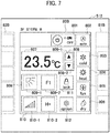
- Fig. 7 illustrates an example of display in an individual air-conditioner management window 80B according to another embodiment.
- the individual air-conditioner management window 80B in Fig. 7 which is formed so as to be vertically long, power button information 801, automatic-working-mode button information 802, cooling-mode button information 803, heating-mode button information 804, ventilation-mode button information 805, dehumidifying-mode button information 806, set-temperature information 807, set-temperature change button information 808, wind-direction change button information 809, air-volume change button information 810, lock button information 811, and option button information 812 that are components similar to those in the horizontally-long individual air-conditioner management window 80A illustrated in Fig. 4 are displayed so as to be fit in the vertically-long window.
- a first wind-direction area 809-1 and a second wind-direction area 809-2 that are components of the information 809 are arranged and displayed in lateral direction in the same manner as those displayed in the individual air-conditioner management window 80A.
- a first air-volume area 810-1 and a second air-volume area 810-2 that are components of the information 810 are arranged and displayed in lateral direction.
- a displaying area for graphic information and a displaying area for text information are arranged and displayed in lateral direction in each button information associated with a function for which working condition is changed in steps every time a touch operation is performed.
- a user in controlling a working condition of an air conditioner on a touch panel, a user can visually perceive a change in the working condition made by his operation also in a case where the working condition is displayed in a position of a control button.
- the controller 20 serving as a central management apparatus may be formed as the facility management apparatus by mounting of a touch panel therein and provision of functions similar to those of the above-described CPU 52 thereto.
Landscapes
- Engineering & Computer Science (AREA)
- Computer Networks & Wireless Communication (AREA)
- Combustion & Propulsion (AREA)
- General Physics & Mathematics (AREA)
- Human Computer Interaction (AREA)
- Chemical & Material Sciences (AREA)
- Physics & Mathematics (AREA)
- Mechanical Engineering (AREA)
- General Engineering & Computer Science (AREA)
- Air Conditioning Control Device (AREA)
- Selective Calling Equipment (AREA)
- Digital Computer Display Output (AREA)
- User Interface Of Digital Computer (AREA)
Abstract
Description
- Embodiments of the present invention relate to a facility management apparatus using a touch panel and to a management-window generation method.
- Generally, a working condition of an air conditioner is controlled by a user using a remote controller that is communicably connected. In such a remote controller of an air conditioner, control buttons for controlling a working condition concerning each function of the air conditioner and a display unit for displaying a working condition or the like concerning each function are provided separately from each other. When a user operates a control button of the remote controller, the user visually perceives a change in displayed information displayed on the display unit, about a working condition concerning a corresponding function, thereby recognizing that his operation has been normally accepted.
- Patent Literature 1:
JP No. 5646797 B2 - In recent years, in a remote controller for controlling a working condition of an air conditioner, a capacitive touch panel or the like is used in many cases. In such a remote controller using a touch panel, for some functions, positions of pieces of displayed information indicating working conditions are set as control buttons for the functions. In this case, a user can easily change a working condition concerning each of the functions by a touch operation on a position where the working condition is displayed on the touch panel.
- However, in a case where displayed information about a working condition concerning a predetermined function and a control button for the predetermined function are set in the same position, the displayed information is hidden with a user's finger during a touch operation. Thus, the user cannot visually perceive a change that has been made in the displayed information by his operation. Being unable to visually perceive a change in displayed information makes a user uncertain about whether his operation has been normally accepted in some cases.
- In this connection, one possible solution is to increase the size of displayed information about a working condition to such a degree that a part of the displayed information extends off a user's finger during a touch operation. This solution may allow the user to recognize a change in displayed information, but cannot ensure it. Further, because of a limitation to the size of a touch panel, it is difficult to enormously increase the size of displayed information about all functions.
- The invention has been made in view of the above-described situations, it is an object to provide a facility management apparatus and a management-window generation method that allow a user to visually perceive a change that is made in a working condition of the facility equipment by his operation on a touch panel in controlling the working condition.
- To attain the above-described object, a remote controller of an air conditioner according to embodiments includes a displayed-information generation unit, a touch panel, an operation determination unit, and a working-control information generation unit. The displayed-information generation unit generates displayed information in which a first area that displays graphic information indicating a current working condition of facility equipment and a second area that displays text information indicating the working condition, are arranged and displayed. Then, when an operation of changing the working condition is performed, the displayed-information generation unit changes the graphic information and the text information based on a post-change working condition. The touch panel displays the generated displayed information. When an operation is performed on any position in the first area or the second area that are displayed, the touch panel inputs operation information corresponding to the operation. The operation determination unit determines an operation based on the input operation information. The working-control information generation unit generates working-control information for changing a working condition of the facility equipment based on the determined operation.
-
-
Fig. 1 is an overall view illustrating an air conditioning system using a tablet terminal serving as a facility management apparatus according to an embodiment of the present invention. -
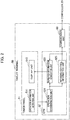
Fig. 2 is a block diagram illustrating a configuration of the tablet terminal serving as the facility management apparatus according to the embodiment of the present invention. -
Fig. 3 illustrates an example of a general air-conditioner management window displayed on the tablet terminal serving as the facility management apparatus according to the embodiment of the present invention. -
Fig. 4 illustrates an example of a horizontally-long individual air-conditioner management window displayed on the tablet terminal serving as the facility management apparatus according to the embodiment of the present invention. -
Fig. 5 is a transition diagram of displayed information in a position of air-volume change button information in the individual air-conditioner management window displayed on the tablet terminal serving as the facility management apparatus according to the embodiment of the present invention. -
Fig. 6 is a transition diagram of displayed information in a position of wind-direction change button information in the individual air-conditioner management window displayed on the tablet terminal serving as the facility management apparatus according to the embodiment of the present invention. -
Fig. 7 illustrates an example of a vertically-long individual air-conditioner management window displayed on the tablet terminal serving as the facility management apparatus according to the embodiment of the present invention. - As an embodiment of the present invention, a configuration of an air conditioning system using a tablet terminal will be described with reference to
Fig. 1 . Anair conditioning system 1 according to the present embodiment includes a plurality of air conditioners (indoor units) 10-1 to 10-100 that are installed in a 10-floor building and are objects being managed, acontroller 20 that is connected to the air conditioners 10-1 to 10-100 and serves as a central management apparatus, access points 40-1 to 40-3 for wireless communication that are connected to thecontroller 20 via ahub 30, a tablet terminal 50-1 that is wirelessly connected to the access point 40-1, a tablet terminal 50-2 that is wirelessly connected to the access point 40-2, and a tablet terminal 50-3 that is wirelessly connected to the access point 40-3. The tablet terminals 50-1 to 50-3 are operated by a manager of theair conditioning system 1. Additionally, only a single tablet terminal may be provided for use in theair conditioning system 1. - A store A occupies the first floor of the building and the air conditioners 10-1 to 10-10 are installed in the store A. Further, a store B occupies the second floor and the air conditioners 10-11 to 10-20 are installed in the store B. Similarly, stores C to J occupy the third to tenth floors, respectively, and the air conditioners 10-21 to 10-30, ..., and 10-91 to 10-100 are installed in the stores, respectively.
- Each of the air conditioners 10-1 to 10-100 has a cooling function, a heating function, a ventilation function, and a dehumidifying function. Alternatively, the air conditioner has only a cooling function and a ventilation function in some cases. Further, each of the air conditioners 10-1 to 10-100 is configured such that a wind direction of air blow can be changed in five steps and an air volume of air blow can be changed in five steps during working for each of the above-described functions.
- In the
air conditioning system 1, the plurality of air conditioners 10-1 to 10-100 installed in the building correspond to facility equipment and the tablet terminals 50-1 to 50-3 correspond to facility management apparatuses. - Hereinafter, the air conditioners 10-1 to 10-100 will be referred to as an "air conditioner 10" unless identification of any of them is necessary. Similarly, the tablet terminals 50-1 to 50-3 will be referred to as a "
tablet terminal 50" unless identification of any of them is necessary. Further similarly, the access points 40-1 to 40-3 will be referred to as an "access point 40" unless identification of any of them is necessary. - The
controller 20 communicates with the air conditioners 10-1 to 10-100, to transmit working-control information for controlling working of the air conditioners 10-1 to 10-100 as needed and acquire working-condition information about the air conditioners 10-1 to 10-100 at predetermined time intervals. - Each of the
tablet terminals 50 includes atouch panel 51, aCPU 52, and acommunication unit 53 as illustrated inFig. 2 . Thetouch panel 51 includes an operation-information detection unit 511 and adisplay unit 512. The operation-information detection unit 511 detects an operation achieved by a touch of a manager's finger or the like on thetouch panel 51. Thedisplay unit 512 displays a management window generated for each of the air conditioners 10-1 to 10-100 by a displayed-information generation unit 522 that will be described later. - The
CPU 52 includes anoperation determination unit 521, the displayed-information generation unit 522, and a working-controlinformation generation unit 523. Theoperation determination unit 521 determines an operation performed by a manager, based on operation information detected by the operation-information detection unit 511 and displayed information displayed on thedisplay unit 512. Examples of an operation include an operation of designating an air conditioner as an object being managed, an operation of changing a working condition of the designated air conditioner, and the like. The displayed-information generation unit 522 generates displayed information that is to be displayed on thedisplay unit 512, based on an operation determined by theoperation determination unit 521. The working-controlinformation generation unit 523 generates working-control information about the air conditioner 10 being controlled, based on an operation determined by theoperation determination unit 521. Thecommunication unit 53 communicates with thecontroller 20 via the access point 40. - Next, operations of the
air conditioning system 1 according to the embodiment will be described. In theair conditioning system 1, thecontroller 20 acquires working-condition information about the air conditioners 10-1 to 10-100 at predetermined time intervals and holds them. - In order for a manager to manage the air conditioners 10-1 to 10-100 using the
tablet terminal 50, the displayed-information generation unit 522 acquires the most recent working-condition information about the air conditioners 10-1 to 10-100 from thecontroller 20 and generates displayed information for a general air-conditioner management window 60 using the acquired information. - The general air-
conditioner management window 60 includes area displaying sections 61-1 to 61-10 and air-conditioner icon displaying sections 62-1 to 62-10 that correspond to the first floor (the store A) to the tenth floor (the store J), respectively, as illustrated inFig. 3 . In the area displaying section 61-1 corresponding to the first floor, text information "FIRST FLOOR (STORE A)" is provided. In the air-conditioner icon displaying section 62-1, air-conditioner icons 63-1 to 63-10 respectively corresponding to the air conditioners 10-1 to 10-10 installed on the first floor are provided. Further, in the area displaying section 61-2 corresponding to the second floor, text information "SECOND FLOOR (STORE B)" is provided. In the air-conditioner icon displaying section 62-2, air-conditioner icons 63-11 to 63-20 respectively corresponding to the air conditioners 10-11 to 10-20 installed on the second floor are provided. In the same manner, in the area displaying sections 61-3 to 61-10 corresponding to the third to tenth floors, pieces of text information "THIRD FLOOR (STORE C)" to "TENTH FLOOR (STORE J)" are provided, respectively. In the air-conditioner icon displaying sections 62-3 to 62-10, air-conditioner icons 63-21 to 63-30 ..., and 63-91 to 63-100 corresponding to the air conditioners 10-21 to 10-30 ..., and 10-91 to 10-100 are provided, respectively. - Each of the air-conditioner icons 63-1 to 63-100 functions as a control switch for controlling ON/OFF of its corresponding one of the air conditioners 10-1 to 10-100. Meanwhile, displayed information in the area displaying sections and the air-conditioner icon displaying sections are changed if appropriate, depending on the number of floors of a building being managed or the number of installed air conditioners.
- The generated displayed information for the general air-
conditioner management window 60 is sent to thedisplay unit 512 of thetouch panel 51 and is displayed thereon. It is additionally noted that inFig. 3 , only pieces of information corresponding to the first to third floors are displayed in the general air-conditioner management window 60 because of a space on thedisplay unit 512 not enough to display all pieces of information in the general air-conditioner management window 60. A viewing area in the general air-conditioner management window 60 is moved by an operation on ascroll bar 70 at the right edge of the window, so that pieces of information about the floors that are currently not displayed are displayed. - Though the present embodiment describes a case where an air-conditioner icon is in one-to-one correspondence with an air conditioner, the invention is not limited to that. One air-conditioner icon can correspond to a plurality of air conditioners. In a case where one air-conditioner icon corresponds to a plurality of air conditioners, an operation on the one air-conditioner icon can control working of the corresponding plurality of air conditioners at a time.
- In the general air-
conditioner management window 60 displayed in the above-described manner, when a manager performs a predetermined operation (double-tap, for example) on any of the air-conditioner icons, for example, on the air-conditioner icon 63-11, an individual air-conditioner management window 80A for minutely controlling a working condition of the corresponding air conditioner 10-11 is generated by the displayed-information generation unit 522 and is displayed on thedisplay unit 512. -
Fig. 4 illustrates an example of the individual air-conditioner management window 80A displayed on thedisplay unit 512. The individual air-conditioner management window 80A inFig. 4 is formed so as to be horizontally long. In the window, there are displayedpower button information 801, automatic-working-mode button information 802, cooling-mode button information 803, heating-mode button information 804, ventilation-mode button information 805, dehumidifying-mode button information 806, set-temperature information 807, set-temperaturechange button information 808, wind-directionchange button information 809, air-volumechange button information 810,lock button information 811, andoption button information 812. - The
power button information 801 is formed of graphic information indicating a current state of power, ON or OFF, of the corresponding air conditioner 10-11 and text information "ON" and "OFF". The graphic information and the text information "ON" are lighted during an ON state of power, and only the text information "OFF" is lighted during an OFF state of power. The automatic-working-mode button information 802 is formed of graphic information indicating an automatic-working mode and text information "Auto". The graphic information and the text information are lighted during working in an automatic-working mode. The cooling-mode button information 803 is formed of graphic information indicating a cooling mode and text information "cold". The graphic information and the text information are lighted during working in a cooling mode. The heating-mode button information 804 is formed of graphic information indicating a heating mode and text information "heat". The graphic information and the text information are lighted during working in a heating mode. The ventilation-mode button information 805 is formed of graphic information indicating a ventilation mode and text information "fan". The graphic information and the text information are lighted during working in a ventilation mode. The dehumidifying-mode button information 806 is formed of graphic information indicating a dehumidifying mode and text information "dry". The graphic information and the text information are lighted during working in a dehumidifying mode. - The set-
temperature information 807 is formed of text information "23.5°C" indicating a current set temperature of the corresponding air conditioner 10-11. The set-temperaturechange button information 808 is formed of graphic information 808-1 of an upward arrow for increasing a set temperature of the corresponding air conditioner 10 by predetermined degrees and graphic information 808-2 of a downward arrow for reducing the set temperature by predetermined degrees. - The wind-direction
change button information 809 is formed of a first wind-direction area 809-1 that displays graphic information indicating a current wind direction and a second wind-direction area 809-2 that displays text information "F1" indicating a current wind direction. The first and second wind-direction areas 809-1 and 809-2 are arranged in lateral direction. Each of the first wind-direction area 809-1 and the second wind-direction area 809-2 has a lateral width substantially equal to the width of a human forefinger. It is preferable that the lateral width of a human forefinger is larger than the diameter of a typical adult's finger (12 mm) compliant with IEC 61032 standard, for example. Because of this width, when a manager touches one of the first wind-direction area 809-1 and the second wind-direction area 809-2, the manager can visually perceive displayed information in the other area. However, in a case where there is a limitation to the size of a window, the width of the area is set to 12 mm exactly equal to the diameter of a finger. - The air-volume
change button information 810 is formed of a first air-volume area 810-1 that displays graphic information indicating a current air volume and a second air-volume area 810-2 that displays text information "H+" indicating a current air volume. The first and second air-volume areas 810-1 and 810-2 are arranged in lateral direction. Each of the first air-volume area 810-1 and the second air-volume area 810-2, like the first wind-direction area 809-1 and the second wind-direction area 809-2 described above, has a lateral width substantially equal to the width of a human forefinger. Additionally, the first air-volume area 810-1 and the second air-volume area 810-2 do not need to be in complete contact with each other, and may be arranged close to each other with a small clearance therebetween as illustrated inFig. 4 . - The
lock button information 811 is formed of graphic information indicating an operation of setting an air conditioner to a state in which no operation on all pieces of the above-described button information (801 to 810) is accepted, and text information "lock". Theoption button information 812 is formed of graphic information indicating an operation of activating an optional function of the corresponding air conditioner 10 and text information "option". - When a manager performs a touch operation on any of positions of the pieces of the button information on the individual air-
conditioner management window 80A in which the above-described pieces of information are being displayed, its corresponding operation information is detected by the operation-information detection unit 511. Then, theoperation determination unit 521 determines the operation performed by the manager, based on the operation information detected by the operation-information detection unit 511 and displayed information displayed on thedisplay unit 512. In other words, it is determined which of buttons has been operated. After theoperation determination unit 521 determines the operation, the working-controlinformation generation unit 523 generates working-control information for changing a working condition of the air conditioner 10-11 being controlled, based on the determined operation. The generated working-control information is transmitted to the corresponding air conditioner 10-11 via thecommunication unit 53 and thecontroller 20, and the working condition is changed. - Further, when the
operation determination unit 521 determines an operation, its corresponding button information in the individual air-conditioner management window 80A is changed in accordance with the determined operation by the displayed-information generation unit 522. For example, when any of pieces of thepower button information 801 to the dehumidifying-mode button information 806 on the individual air-conditioner management window 80A is operated, the button information having been operated is lighted by the displayed-information generation unit 522. - Moreover, when either the
lock button information 811 or theoption button information 812 on the individual air-conditioner management window 80A is operated, the displayed-information generation unit 522 displays a pop-up window for providing more detailed settings. Then, theoperation determination unit 521 determines an operation performed on the pop-up window, so that the working-controlinformation generation unit 523 generates working-control information. Thus, a working condition of a corresponding air conditioner is changed. - On the right side and the left side of the individual air-
conditioner management window 80A, there are respectively displayed small parts of individual air-conditioner management windows for air-conditioner numbers before and after the air conditioner 10-11 that is currently displayed. InFig. 4 , an individual air-conditioner management window 82A on the left side is an end portion of the individual air-conditioner management window for the air conditioner 10-10, and an individual air-conditioner management window 81A on the right side is an end portion of the individual air-conditioner management window for the air conditioner 10-12. When a manager performs a rightward flick operation on thetouch panel 51 on which the above-described information about the windows is displayed, the individual air-conditioner management window 82A for the air conditioner 10-10 on the left side can be caused to move to the center. In the same manner, when a manager operates a leftward flick operation on thetouch panel 51, the individual air-conditioner management window 81A for the air conditioner 10-12 on the left side can be caused to move to the center. - Here, there will be described processes performed when the air-volume
change button information 810 on the individual air-conditioner management window 80A is operated while the air conditioner 10-11 is working with the maximum air volume. In the following description, five levels of air volumes that can be set during working of the air conditioner 10 will be described as a first air volume (High+), a second air volume (High), a third air volume (Middle), a fourth air volume (Low), and a fifth air volume (Low-) in a descending order of air volume from the maximum to the minimum. In the present embodiment, in the working-controlinformation generation unit 523, there is established a criterion of generation of air-volume control information for cyclically changing an air volume so that the air volume of the corresponding air conditioner 10 is reduced in steps every time an air-volume changing operation is performed, an air-volume changing operation during working with the minimum air volume (the fifth air volume) causes a transition to an automatic air-volume working mode(Auto) in which an air volume is automatically adjusted, and an air-volume changing operation during an automatic air-volume working mode causes the air volume to return to the maximum air volume (the first air volume).Fig. 5 illustrates transitions of displayed information that is changed every time an air-volume changing operation is performed, in the air-volumechange button information 810 in the individual air-conditioner management window 80A. - First, consider a case where the air conditioner 10-11 is currently working with the first air volume (High+) that is the maximum air volume. In this case, as illustrated in a portion denoted by X1 in
Fig. 5 , graphic information indicating the first air volume (High+) is displayed at the first air-volume area 810-1 of the air-volumechange button information 810 in the individual air-conditioner management window 80A, and text information "H+" indicating the first air volume (High+) is displayed at the second air-volume area 810-2. - Then, when a touch operation is performed on any position in either the first air-volume area 810-1 or the second air-volume area 810-2 of the air-volume
change button information 810, its corresponding operation information is detected by the operation-information detection unit 511. Thereafter, theoperation determination unit 521 determines that an air-volume changing operation has been performed, based on the operation information detected by the operation-information detection unit 511 and displayed information displayed on thedisplay unit 512. - When it is determined that an air-volume changing operation has been performed, the working-control
information generation unit 523 generates air-volume control information that is a kind of working-control information for changing the air volume of the air conditioner 10-11 being controlled, in accordance with the above-described criterion of generation. In this case, there is generated air-volume control information for changing an air volume from the first air volume (High+) currently set in the air conditioner 10-11 to the second air volume (High) that is lower in level by one. The generated air-volume control information is transmitted to the corresponding air conditioner 10-11 via thecommunication unit 53 and thecontroller 20. The air conditioner 10-11, in which the air volume having been set is then changed to the second air volume (High), keeps working. - Further, when the
operation determination unit 521 determines that an air-volume changing operation has been performed, the displayed-information generation unit 522 changes displayed information in the air-volumechange button information 810 in the individual air-conditioner management window 80A as illustrated in a portion denoted by X2. More specifically, displayed information at the first air-volume area 810-1 is changed to graphic information indicating the second air volume (High), and displayed information at the second air-volume area 810-2 is changed to text information "H" indicating the second air volume (High). - In the same manner, when a touch operation is performed on any position in either the first air-volume area 810-1 or the second air-volume area 810-2 while the air conditioner 10-11 is working with the second air volume (High), the air volume of the air conditioner 10-11 is changed to the third air volume (Middle) based on control information generated by the working-control
information generation unit 523. Further, the displayed-information generation unit 522 changes displayed information at the first air-volume area 810-1 and the second air-volume area 810-2 to information indicating the third air volume (Middle) as illustrated in a portion denoted by X3. - Further, when a touch operation is performed on any position in either the first air-volume area 810-1 or the second air-volume area 810-2 while the air conditioner 10-11 is working with the third air volume (Middle), the air volume of the air conditioner 10-11 is changed to the fourth air volume (Low) based on control information generated by the working-control
information generation unit 523. Moreover, the displayed-information generation unit 522 changes displayed information at the first air-volume area 810-1 and the second air-volume area 810-2 to information indicating the fourth air volume (Low) as illustrated in a portion denoted by X4. - Further, when a touch operation is performed on any position in either the first air-volume area 810-1 or the second air-volume area 810-2 while the air conditioner 10-11 is working with the fourth air volume (Low), the air volume of the air conditioner 10-11 is changed to the fifth air volume (Low-) based on control information generated by the working-control
information generation unit 523. Moreover, the displayed-information generation unit 522 changes displayed information at the first air-volume area 810-1 and the second air-volume area 810-2 to information indicating the fifth air volume (Low-) as illustrated in a portion denoted by X5. - Further, when a touch operation is performed on any position in either the first air-volume area 810-1 or the second air-volume area 810-2 while the air conditioner 10-11 is working with the fifth air volume (Low-), the air conditioner 10 is put in an automatic air-volume working mode (Auto) based on control information generated by the working-control
information generation unit 523. Moreover, the displayed-information generation unit 522 changes displayed information at the first air-volume area 810-1 and the second air-volume area 810-2 to information indicating an automatic air-volume working mode (Auto) as illustrated in a portion denoted by X6. - Further, when a touch operation is performed on any position in either the first air-volume area 810-1 or the second air-volume area 810-2 while the air conditioner 10-11 is working in an automatic air-volume working mode, the air volume of the air conditioner 10 is changed to the first air volume (High+) based on control information generated by the working-control
information generation unit 523. Moreover, the displayed-information generation unit 522 changes displayed information at the first air-volume area 810-1 and the second air-volume area 810-2 to information indicating the first air volume (High+) as illustrated in the portion denoted by X1. - Additionally, when a touch operation is performed on any position in either the first air-volume area 810-1 or the second air-volume area 810-2 plural times in a predetermined time (0.5 seconds, for example), the
operation determination unit 521 determines an operation repeatedly. Then, the working-controlinformation generation unit 523 determines a post-change air volume in accordance with the number of touch operations in the predetermined time and transmits air-volume control information for changing an air volume to the determined air volume, to the corresponding air conditioner 10. For example, in a case where a touch operation is performed on any position in either the first air-volume area 810-1 or the second air-volume area 810-2 three times at extremely short time intervals while the air conditioner 10 is working with the first air volume (High+), the working-controlinformation generation unit 523 determines that a post-change air volume is the fourth air volume (Low), and transmits air-volume control information for changing an air volume to the fourth air volume (Low), to the air conditioner 10. - Meanwhile, when the
operation determination unit 521 determines an operation repeatedly, in other words, every time a touch operation is performed, the displayed-information generation unit 522 changes displayed information at the first air-volume area 810-1 and the second air-volume area 810-2 sequentially from information indicating the first air volume (High+) to information indicating the second air volume (High), to information indicating the third air volume (Middle), and to information indicating the fourth air volume (Low) in the stated order. - As described above, in a case where an operation is repeated in a short time, a process of generating and outputting control information in the working-control
information generation unit 523 and a process of changing displayed information in the displayed-information generation unit 522 are performed at different times based on an operation determined by theoperation determination unit 521. Additionally, if an increase of an amount of communicated data in theair conditioning system 1 is allowed, control information may be generated and transmitted every time a touch operation is performed, in the same manner as displayed information is changed. - Moreover, also when an operation is performed on any position in either the first wind-direction area 809-1 or the second wind-direction area 809-2 forming the wind-direction
change button information 809 on the individual air-conditioner management window 80A, the wind direction of the corresponding air conditioner 10-11 is changed in steps and displayed information at the first wind-direction area 809-1 and the second wind-direction area 809-2 is changed every time an operation is performed. - There will be described processes performed when the wind-direction
change button information 809 on the individual air-conditioner management window 80A is operated while the air conditioner 10-11 is working with its wind direction being set to the most upward direction. In the following description, five levels of wind directions that can be set during working of the air conditioner 10 will be described as a first direction (F1), a second direction (F2), a third direction (F3), a fourth direction (F4), and a fifth direction (F5) in an order from the most upward direction to the most downward direction. In the present embodiment, in the working-controlinformation generation unit 523, there is established a criterion of generation of wind-direction control information for cyclically changing a wind direction so that the wind direction of the corresponding air conditioner 10 is changed to a more downward direction in steps every time a wind-direction changing operation is performed, a wind-direction changing operation during working with the wind direction being set to the most downward direction (the fifth direction) causes a transition to a swinging mode (SWING) in which a wind is caused to flow back and forth between the first direction and the fifth direction, and a wind-direction changing operation during a swinging mode causes the wind direction to return to the first direction (F1).Fig. 6 illustrates transitions of displayed information that is changed every time a wind-direction changing operation is performed, in the wind-directionchange button information 809 in the individual air-conditioner management window 80A. - First, consider a case where the air conditioner 10-11 is currently working with its wind direction being set to the first direction (F1) that is the most upward direction. In this case, as illustrated in a portion denoted by Y1 in
Fig. 6 , graphic information indicating the first direction is displayed at the first wind-direction area 809-1 of the wind-directionchange button information 809 in the individual air-conditioner management window 80A, and text information "F1" indicating the first direction is displayed at the second wind-direction area 809-2. - Then, when a touch operation is performed on any position in either the first wind-direction area 809-1 or the second wind-direction area 809-2 forming the wind-direction
change button information 809, its corresponding operation information is detected by the operation-information detection unit 511. Thereafter, theoperation determination unit 521 determines that a wind-direction changing operation has been performed, based on the operation information detected by the operation-information detection unit 511 and displayed information displayed on thedisplay unit 512. - When it is determined that a wind-direction changing operation has been performed, the working-control
information generation unit 523 generates wind-direction control information that is a kind of working-control information for changing the wind direction of the air conditioner 10-11 being controlled, in accordance with the above-described criterion of generation. In this case, there is generated wind-direction control information for changing a wind direction from the first direction (F1) currently set in the air conditioner 10-11 to the second direction (F2) that is more downward in level by one. The generated wind-direction control information is transmitted to the corresponding air conditioner 10-11 via thecommunication unit 53 and thecontroller 20. The air conditioner 10-11, in which the wind direction having been set is then changed to the second direction (F2), keeps working. - Further, when the
operation determination unit 521 determines that a wind-direction changing operation has been performed, the displayed-information generation unit 522 changes displayed information in the wind-directionchange button information 809 in the individual air-conditioner management window 80A as illustrated in a portion denoted by Y2. More specifically, displayed information at the first wind-direction area 809-1 is changed to graphic information indicating the second direction, and displayed information at the second wind-direction area 809-2 is changed to text information "F2" indicating the second direction. - In the same manner, when a touch operation is performed on any position in either the first wind-direction area 809-1 or the second wind-direction area 809-2 while the air conditioner 10-11 is working with its wind direction being set to the second direction (F2), the wind direction of the air conditioner 10-11 is changed to the third direction (F3). Moreover, displayed information at the first wind-direction area 809-1 and the second wind-direction area 809-2 in the individual air-
conditioner management window 80A is changed to information indicating the third direction (F3) as illustrated in a portion denoted by Y3. - Further, when a touch operation is performed on any position in either the first wind-direction area 809-1 or the second wind-direction area 809-2 while the air conditioner 10-11 is working with its wind direction being set to the third direction (F3), the wind direction of the air conditioner 10-11 is changed to the fourth direction (F4). Moreover, displayed information at the first wind-direction area 809-1 and the second wind-direction area 809-2 in the individual air-
conditioner management window 80A is changed to information indicating the fourth direction (F4) as illustrated in a portion denoted by Y4. - Further, when a touch operation is performed on any position in either the first wind-direction area 809-1 or the second wind-direction area 809-2 while the air conditioner 10-11 is working with its wind direction being set to the fourth direction (F4), the wind direction of the air conditioner 10-11 is changed to the fifth direction (F5). Moreover, displayed information at the first wind-direction area 809-1 and the second wind-direction area 809-2 in the individual air-
conditioner management window 80A is changed to information indicating the fifth direction (F5) as illustrated in a portion denoted by Y5. - Further, when a touch operation is performed on any position in either the first wind-direction area 809-1 or the second wind-direction area 809-2 while the air conditioner 10-11 is working with its wind direction being set to the fifth direction (F5), the air conditioner 10 is put in a swinging mode (SWING). Moreover, displayed information at the first wind-direction area 809-1 and the second wind-direction area 809-2 in the individual air-
conditioner management window 80A is changed to information indicating a swinging mode (SWING) as illustrated in a portion denoted by Y6. - Further, when a touch operation is performed on any position in either the first wind-direction area 809-1 or the second wind-direction area 809-2 while the air conditioner 10-11 is working in a swinging mode, the wind direction of the air conditioner 10 is changed to the first direction (F1). Moreover, displayed information at the first wind-direction area 809-1 and the second wind-direction area 809-2 in the individual air-
conditioner management window 80A is changed to information indicating the first direction (F1) as illustrated in the portion denoted by Y1. - Additionally, when a touch operation is performed on any position in either the first wind-direction area 809-1 or the second wind-direction area 809-2 plural times in a predetermined time (0.5 seconds, for example), the
operation determination unit 521 determines an operation repeatedly. Then, the working-controlinformation generation unit 523 determines a post-change wind direction in accordance with the number of touch operations in the predetermined time and transmits wind-direction control information for changing a wind direction to the determined wind direction, to the corresponding air conditioner 10. For example, in a case where a touch operation is performed on any position in either the first wind-direction area 809-1 or the second wind-direction area 809-2 three times at extremely short time intervals while the air conditioner 10 is working with its wind direction being set to the first direction (F1), the working-controlinformation generation unit 523 determines that a post-change wind direction is the fourth direction (F4), and wind-direction control information for changing a wind direction to the fourth direction (F4) is transmitted to the air conditioner 10. - At that time, when the
operation determination unit 521 determines an operation repeatedly, in other words, every time a touch operation is performed, the displayed-information generation unit 522 changes displayed information at the first wind-direction area 809-1 and the second wind-direction area 809-2 sequentially from information indicating the first direction (F1) to information indicating the second direction (F2), to information indicating the third direction (F3), and to information indicating the fourth direction (F4) in the stated order. - As described above, when a touch operation is performed on any position in the air-volume
change button information 810 and the wind-directionchange button information 809, pieces of displayed information in both of a displaying area for text information and a displaying area for graphic information are changed. Thus, if a manager performs a touch operation on a displaying area for graphic information to hide the graphic information displayed in the area with his finger, the manager can visually perceive a change in text information because the displayed text information is not hidden. On the other hand, if a manager performs a touch operation on a displaying area for text information to hide the information displayed in the area with his finger, the manager can visually perceive a change in graphic information because the displayed graphic information is not hidden. By such visual perception of the change, the manager can recognize that an operation of changing an air volume or a wind direction has been normally accepted. In the meantime, text information is literal information and is information including alphabets, Arabic numerals, Hiragana characters, Katakana characters, and any of combinations thereof. - On the other hand, each of the
power button information 801 to the dehumidifying-mode button information 806 is switched between lighting and extinction upon an operation on the button information. Further, in each of thelock button information 811 and theoption button information 812, a pop-up window is displayed upon an operation on the button information. Thus, a user can visually perceive a change in a working condition even during a touch operation. For this reason, each of the above-described pieces of button information is formed of a single area. This allows those pieces of button information to be efficiently displayed in a limited displaying area of thedisplay unit 512. - Furthermore,
Fig. 7 illustrates an example of display in an individual air-conditioner management window 80B according to another embodiment. In the individual air-conditioner management window 80B inFig. 7 , which is formed so as to be vertically long,power button information 801, automatic-working-mode button information 802, cooling-mode button information 803, heating-mode button information 804, ventilation-mode button information 805, dehumidifying-mode button information 806, set-temperature information 807, set-temperaturechange button information 808, wind-directionchange button information 809, air-volumechange button information 810,lock button information 811, andoption button information 812 that are components similar to those in the horizontally-long individual air-conditioner management window 80A illustrated inFig. 4 are displayed so as to be fit in the vertically-long window. - Out of those components, in the wind-direction
change button information 809 for changing a wind direction in steps, a first wind-direction area 809-1 and a second wind-direction area 809-2 that are components of theinformation 809 are arranged and displayed in lateral direction in the same manner as those displayed in the individual air-conditioner management window 80A. Further, in the air-volumechange button information 810 for changing an air volume in steps, a first air-volume area 810-1 and a second air-volume area 810-2 that are components of theinformation 810 are arranged and displayed in lateral direction. Moreover, in the same manner as in a case where the individual air-conditioner management window 80A is displayed, respective parts of individual air-conditioner management windows window 80B are displayed on the right side and the left side of the individual air-conditioner management window 80B. - As described above, also in the vertically-long individual air-
conditioner management window 80B, a displaying area for graphic information and a displaying area for text information are arranged and displayed in lateral direction in each button information associated with a function for which working condition is changed in steps every time a touch operation is performed. Thus, if displayed information in one of the areas that is operated by a manager is hidden with his finger, the manager can visually perceive a change in displayed information in the other area. - According to the above-described embodiments, in controlling a working condition of an air conditioner on a touch panel, a user can visually perceive a change in the working condition made by his operation also in a case where the working condition is displayed in a position of a control button.
- Further, though there has been described an example in which the
tablet terminal 50 is used as the facility management apparatus in the above-described embodiments, thecontroller 20 serving as a central management apparatus may be formed as the facility management apparatus by mounting of a touch panel therein and provision of functions similar to those of the above-describedCPU 52 thereto. - In the above-described embodiments, there has been described a case in which an individual air-conditioner management window for a single air conditioner 10 is displayed and a working condition concerning the function of the air conditioner 10 is changed on the window. However, there may be provided a configuration in which an air-conditioner icon corresponding to a plurality of air conditioners is operated to cause an air-conditioner management window to be displayed, and working conditions concerning the functions of the plurality of air conditioners are changed at a time by a similar operation on the window.
- Hereinabove, the embodiments of the present invention have been described. However, the embodiments have been proposed as examples and are not intended to limit the scope of the invention. The novel embodiments can be carried out in other various forms, and various omissions, replacements, and alterations are possible within a range not departing from the gist of the invention. The embodiments and modifications thereof are included in the scope or gist of the invention and are included in the invention recited in claims and in the range of equivalence thereof.
Claims (10)
- A facility management apparatus comprising:a displayed-information generation unit configured to generate displayed information in which a first area and a second area that display information indicating a current working condition of facility equipment being managed, in different forms, are arranged and displayed; anda touch panel configured to display the displayed information generated by the displayed-information generation unit and to detect a touch operation on any position in the displayed information that is displayed, whereinthe displayed-information generation unit changes the displayed information in the first area and the second area upon detection of a touch operation on the touch panel.
- The facility management apparatus according to claim 1, wherein graphic information indicating the working condition of the facility equipment is displayed in the first area and text information indicating the working condition is displayed in the second area.
- The facility management apparatus according to claim 1 or 2, wherein the displayed-information generation unit changes the displayed information in the first area and the second area in steps every time a touch operation on the touch panel is detected.
- The facility management apparatus according to any of claims 1 to 3, wherein the displayed-information generation unit cyclically changes the displayed information in the first area and the second area every time a touch operation on the touch panel is detected.
- The facility management apparatus according to any of claims 1 to 4, wherein the displayed-information generation unit generates the displayed information by arrangement in lateral direction of the first area and the second area.
- The facility management apparatus according to any of claims 1 to 5, wherein each of the first area and the second area has a lateral width of 12 mm or larger.
- The facility management apparatus according to any of claims 1 to 6, further comprising:a control information generation unit configured to generate control information for changing the working condition of the facility equipment upon detection of a touch operation on the touch panel; anda communication unit configured to transmit the control information generated by the control information generation unit to the facility equipment.
- A facility management apparatus comprising:a displayed-information generation unit configured to generate displayed information in which a first air-volume area that displays graphic information indicating a current air volume of an air conditioner being managed and a second air-volume area that displays text information indicating the air volume, are arranged and displayed; anda touch panel configured to display the displayed information generated by the displayed-information generation unit and to detect a touch operation on any position in the displayed information that is displayed, whereinthe displayed-information generation unit changes the displayed information in the first air-volume area and the second air-volume area every time a touch operation on the touch panel is detected.
- A management-window generation method performed by a facility management apparatus that manages facility equipment, comprising:a displayed-information generating step of generating displayed information in which a first area and a second area that display a working condition of the facility equipment in different forms, are arranged and displayed;a displaying step of displaying the generated displayed information on a touch panel; anda displayed-information changing step of changing the displayed information in the first area and the second area upon detection of a touch operation on the touch panel.
- The management-window generation method according to claim 9, wherein in the displayed-information generating step and the displayed-information changing step, graphic information indicating the working condition of the facility equipment is displayed in one of the first area and the second area and text information indicating the working condition is displayed in another area.
Applications Claiming Priority (1)
| Application Number | Priority Date | Filing Date | Title |
|---|---|---|---|
| PCT/JP2018/020946 WO2019229929A1 (en) | 2018-05-31 | 2018-05-31 | Equipment management device using touch panel, and method for generating management screen |
Publications (3)
| Publication Number | Publication Date |
|---|---|
| EP3806481A1 true EP3806481A1 (en) | 2021-04-14 |
| EP3806481A4 EP3806481A4 (en) | 2021-06-02 |
| EP3806481B1 EP3806481B1 (en) | 2025-11-12 |
Family
ID=68697291
Family Applications (1)
| Application Number | Title | Priority Date | Filing Date |
|---|---|---|---|
| EP18920907.5A Active EP3806481B1 (en) | 2018-05-31 | 2018-05-31 | Equipment management device using touch panel, and method for generating management screen |
Country Status (4)
| Country | Link |
|---|---|
| EP (1) | EP3806481B1 (en) |
| JP (1) | JP7015917B2 (en) |
| CN (1) | CN112237006B (en) |
| WO (1) | WO2019229929A1 (en) |
Families Citing this family (2)
| Publication number | Priority date | Publication date | Assignee | Title |
|---|---|---|---|---|
| USD977996S1 (en) | 2020-12-18 | 2023-02-14 | Research Products Corporation | Heating ventilation and air conditioning controller |
| USD977343S1 (en) | 2021-03-09 | 2023-02-07 | Research Products Corporation | Heating ventilation and air conditioning controller |
Family Cites Families (14)
| Publication number | Priority date | Publication date | Assignee | Title |
|---|---|---|---|---|
| CS215108B2 (en) | 1977-07-15 | 1982-07-30 | Wellcome Found | Method of making the interferrone |
| JP3403320B2 (en) * | 1997-07-08 | 2003-05-06 | 東芝キヤリア株式会社 | Wireless remote control for air conditioner |
| JP2000236585A (en) | 1999-02-15 | 2000-08-29 | Nippon Telegr & Teleph Corp <Ntt> | Device control method and device, and control server |
| JP2007181068A (en) * | 2005-12-28 | 2007-07-12 | Funai Electric Co Ltd | Remote controller |
| JP2008258894A (en) * | 2007-04-04 | 2008-10-23 | Seiko Epson Corp | Remote controller, video display device and video display system |
| FR2939555B1 (en) * | 2008-12-10 | 2015-09-18 | Somfy Sas | METHOD FOR OPERATING A DEVICE FOR CONTROLLING DOMOTIC EQUIPMENT |
| JP5091267B2 (en) * | 2010-02-18 | 2012-12-05 | シャープ株式会社 | Operating device, electronic device equipped with the operating device, image processing apparatus, and operating method |
| JP2012003508A (en) * | 2010-06-16 | 2012-01-05 | Toshiba Corp | Information processor, method and program |
| JP5355505B2 (en) * | 2010-06-24 | 2013-11-27 | 三菱電機株式会社 | Equipment control device |
| JP5691545B2 (en) * | 2011-01-19 | 2015-04-01 | 株式会社富士通ゼネラル | Level display device and remote controller using the level display device |
| US9222693B2 (en) * | 2013-04-26 | 2015-12-29 | Google Inc. | Touchscreen device user interface for remote control of a thermostat |
| KR20140070040A (en) * | 2012-11-30 | 2014-06-10 | 삼성전자주식회사 | Apparatus and method for managing a plurality of objects displayed on touch screen |
| JP5835310B2 (en) * | 2013-12-12 | 2015-12-24 | ダイキン工業株式会社 | Remote control device for heat pump system |
| JP2018055288A (en) * | 2016-09-27 | 2018-04-05 | 東芝キヤリア株式会社 | Facility management device and facility management screen generation method |
-
2018
- 2018-05-31 WO PCT/JP2018/020946 patent/WO2019229929A1/en not_active Ceased
- 2018-05-31 CN CN201880094059.8A patent/CN112237006B/en active Active
- 2018-05-31 JP JP2020522502A patent/JP7015917B2/en active Active
- 2018-05-31 EP EP18920907.5A patent/EP3806481B1/en active Active
Also Published As
| Publication number | Publication date |
|---|---|
| EP3806481B1 (en) | 2025-11-12 |
| WO2019229929A1 (en) | 2019-12-05 |
| EP3806481A4 (en) | 2021-06-02 |
| CN112237006A (en) | 2021-01-15 |
| CN112237006B (en) | 2023-06-30 |
| JP7015917B2 (en) | 2022-02-03 |
| JPWO2019229929A1 (en) | 2021-07-01 |
Similar Documents
| Publication | Publication Date | Title |
|---|---|---|
| US10764157B2 (en) | Control apparatus for controlling an operation of at least one electronic device | |
| US10120532B2 (en) | Control apparatus for controlling an operation of at least one electronic device | |
| US10598400B2 (en) | Remote control device | |
| US9964327B2 (en) | Air-conditioning remote controller and air-conditioning system | |
| CN101668995A (en) | air-conditioning controller | |
| US9830887B2 (en) | HVAC controls and controllers including alphanumeric displays | |
| EP2843318B1 (en) | Room management apparatus and method | |
| US10107516B2 (en) | Remote controller, operation screen display method, and program | |
| JP6079358B2 (en) | Air conditioner remote control device | |
| EP3806481B1 (en) | Equipment management device using touch panel, and method for generating management screen | |
| KR20210010074A (en) | Vehicle and controlling method of vehicle | |
| WO2018127954A1 (en) | Radio communication system | |
| EP3517850B1 (en) | Remote controller for air conditioning | |
| US10606255B2 (en) | Plant monitor and control system | |
| KR20170090651A (en) | Apparatus for controlling air conditioning and controlling method thereof | |
| JP2003345325A (en) | Operation display device | |
| EP3809058B1 (en) | Air conditioner management device, and method for generating screen image for managing air conditioner | |
| KR102782643B1 (en) | Vehicle and controlling method thereof | |
| US20250110629A1 (en) | Operation terminal device and display control method for user interface thereof | |
| JP2018112380A (en) | Air conditioning management device and display control method thereof | |
| JP2013102446A (en) | Remote control device | |
| CN116194717A (en) | Operation terminal and home appliance control system | |
| JP7409405B2 (en) | Operation terminal device and its user interface display control method | |
| KR20210153264A (en) | Vehicle and controlling method of vehicle | |
| JP2011214774A (en) | Centralized controller for air conditioner |
Legal Events
| Date | Code | Title | Description |
|---|---|---|---|
| STAA | Information on the status of an ep patent application or granted ep patent |
Free format text: STATUS: THE INTERNATIONAL PUBLICATION HAS BEEN MADE |
|
| PUAI | Public reference made under article 153(3) epc to a published international application that has entered the european phase |
Free format text: ORIGINAL CODE: 0009012 |
|
| STAA | Information on the status of an ep patent application or granted ep patent |
Free format text: STATUS: REQUEST FOR EXAMINATION WAS MADE |
|
| 17P | Request for examination filed |
Effective date: 20201229 |
|
| AK | Designated contracting states |
Kind code of ref document: A1 Designated state(s): AL AT BE BG CH CY CZ DE DK EE ES FI FR GB GR HR HU IE IS IT LI LT LU LV MC MK MT NL NO PL PT RO RS SE SI SK SM TR |
|
| AX | Request for extension of the european patent |
Extension state: BA ME |
|
| REG | Reference to a national code |
Ref country code: DE Ref legal event code: R079 Free format text: PREVIOUS MAIN CLASS: H04Q0009000000 Ipc: G08C0017020000 Ref document number: 602018087209 Country of ref document: DE |
|
| A4 | Supplementary search report drawn up and despatched |
Effective date: 20210506 |
|
| RIC1 | Information provided on ipc code assigned before grant |
Ipc: G08C 17/02 20060101AFI20210429BHEP Ipc: H04Q 9/00 20060101ALI20210429BHEP Ipc: F24F 11/52 20180101ALI20210429BHEP Ipc: H04M 11/00 20060101ALI20210429BHEP |
|
| DAV | Request for validation of the european patent (deleted) | ||
| DAX | Request for extension of the european patent (deleted) | ||
| STAA | Information on the status of an ep patent application or granted ep patent |
Free format text: STATUS: EXAMINATION IS IN PROGRESS |
|
| 17Q | First examination report despatched |
Effective date: 20240129 |
|
| GRAP | Despatch of communication of intention to grant a patent |
Free format text: ORIGINAL CODE: EPIDOSNIGR1 |
|
| STAA | Information on the status of an ep patent application or granted ep patent |
Free format text: STATUS: GRANT OF PATENT IS INTENDED |
|
| INTG | Intention to grant announced |
Effective date: 20250602 |
|
| GRAS | Grant fee paid |
Free format text: ORIGINAL CODE: EPIDOSNIGR3 |
|
| GRAA | (expected) grant |
Free format text: ORIGINAL CODE: 0009210 |
|
| STAA | Information on the status of an ep patent application or granted ep patent |
Free format text: STATUS: THE PATENT HAS BEEN GRANTED |
|
| RAP3 | Party data changed (applicant data changed or rights of an application transferred) |
Owner name: CARRIER JAPAN CORPORATION |
|
| AK | Designated contracting states |
Kind code of ref document: B1 Designated state(s): AL AT BE BG CH CY CZ DE DK EE ES FI FR GB GR HR HU IE IS IT LI LT LU LV MC MK MT NL NO PL PT RO RS SE SI SK SM TR |
|
| REG | Reference to a national code |
Ref country code: CH Ref legal event code: F10 Free format text: ST27 STATUS EVENT CODE: U-0-0-F10-F00 (AS PROVIDED BY THE NATIONAL OFFICE) Effective date: 20251112 Ref country code: GB Ref legal event code: FG4D |
|
| REG | Reference to a national code |
Ref country code: IE Ref legal event code: FG4D |
|
| REG | Reference to a national code |
Ref country code: DE Ref legal event code: R096 Ref document number: 602018087209 Country of ref document: DE |
|
| P01 | Opt-out of the competence of the unified patent court (upc) registered |
Free format text: CASE NUMBER: UPC_APP_0013045_3806481/2025 Effective date: 20251112 |
|
| REG | Reference to a national code |
Ref country code: NL Ref legal event code: MP Effective date: 20251112 |
|
| PG25 | Lapsed in a contracting state [announced via postgrant information from national office to epo] |
Ref country code: ES Free format text: LAPSE BECAUSE OF FAILURE TO SUBMIT A TRANSLATION OF THE DESCRIPTION OR TO PAY THE FEE WITHIN THE PRESCRIBED TIME-LIMIT Effective date: 20251112 |
|
| REG | Reference to a national code |
Ref country code: LT Ref legal event code: MG9D |
|
| PG25 | Lapsed in a contracting state [announced via postgrant information from national office to epo] |
Ref country code: NO Free format text: LAPSE BECAUSE OF FAILURE TO SUBMIT A TRANSLATION OF THE DESCRIPTION OR TO PAY THE FEE WITHIN THE PRESCRIBED TIME-LIMIT Effective date: 20260212 |
|
| PG25 | Lapsed in a contracting state [announced via postgrant information from national office to epo] |
Ref country code: AT Free format text: LAPSE BECAUSE OF FAILURE TO SUBMIT A TRANSLATION OF THE DESCRIPTION OR TO PAY THE FEE WITHIN THE PRESCRIBED TIME-LIMIT Effective date: 20251112 Ref country code: FI Free format text: LAPSE BECAUSE OF FAILURE TO SUBMIT A TRANSLATION OF THE DESCRIPTION OR TO PAY THE FEE WITHIN THE PRESCRIBED TIME-LIMIT Effective date: 20251112 Ref country code: HR Free format text: LAPSE BECAUSE OF FAILURE TO SUBMIT A TRANSLATION OF THE DESCRIPTION OR TO PAY THE FEE WITHIN THE PRESCRIBED TIME-LIMIT Effective date: 20251112 |
|
| REG | Reference to a national code |
Ref country code: AT Ref legal event code: MK05 Ref document number: 1857481 Country of ref document: AT Kind code of ref document: T Effective date: 20251112 |
|
| PG25 | Lapsed in a contracting state [announced via postgrant information from national office to epo] |
Ref country code: NL Free format text: LAPSE BECAUSE OF FAILURE TO SUBMIT A TRANSLATION OF THE DESCRIPTION OR TO PAY THE FEE WITHIN THE PRESCRIBED TIME-LIMIT Effective date: 20251112 |
|
| PG25 | Lapsed in a contracting state [announced via postgrant information from national office to epo] |
Ref country code: RS Free format text: LAPSE BECAUSE OF FAILURE TO SUBMIT A TRANSLATION OF THE DESCRIPTION OR TO PAY THE FEE WITHIN THE PRESCRIBED TIME-LIMIT Effective date: 20260212 |
|
| PG25 | Lapsed in a contracting state [announced via postgrant information from national office to epo] |
Ref country code: IS Free format text: LAPSE BECAUSE OF FAILURE TO SUBMIT A TRANSLATION OF THE DESCRIPTION OR TO PAY THE FEE WITHIN THE PRESCRIBED TIME-LIMIT Effective date: 20260312 |
|
| PG25 | Lapsed in a contracting state [announced via postgrant information from national office to epo] |
Ref country code: PT Free format text: LAPSE BECAUSE OF FAILURE TO SUBMIT A TRANSLATION OF THE DESCRIPTION OR TO PAY THE FEE WITHIN THE PRESCRIBED TIME-LIMIT Effective date: 20260312 |
|
| PG25 | Lapsed in a contracting state [announced via postgrant information from national office to epo] |
Ref country code: PL Free format text: LAPSE BECAUSE OF FAILURE TO SUBMIT A TRANSLATION OF THE DESCRIPTION OR TO PAY THE FEE WITHIN THE PRESCRIBED TIME-LIMIT Effective date: 20251112 |
|
| PG25 | Lapsed in a contracting state [announced via postgrant information from national office to epo] |
Ref country code: LV Free format text: LAPSE BECAUSE OF FAILURE TO SUBMIT A TRANSLATION OF THE DESCRIPTION OR TO PAY THE FEE WITHIN THE PRESCRIBED TIME-LIMIT Effective date: 20251112 |
|
| PG25 | Lapsed in a contracting state [announced via postgrant information from national office to epo] |
Ref country code: BG Free format text: LAPSE BECAUSE OF FAILURE TO SUBMIT A TRANSLATION OF THE DESCRIPTION OR TO PAY THE FEE WITHIN THE PRESCRIBED TIME-LIMIT Effective date: 20251112 |