EP3806362A1 - Wireless transmitting device, wireless receiving device, and wireless transmitting method - Google Patents
Wireless transmitting device, wireless receiving device, and wireless transmitting method Download PDFInfo
- Publication number
- EP3806362A1 EP3806362A1 EP20200314.1A EP20200314A EP3806362A1 EP 3806362 A1 EP3806362 A1 EP 3806362A1 EP 20200314 A EP20200314 A EP 20200314A EP 3806362 A1 EP3806362 A1 EP 3806362A1
- Authority
- EP
- European Patent Office
- Prior art keywords
- data
- frame
- sub
- mcs
- modulated
- Prior art date
- Legal status (The legal status is an assumption and is not a legal conclusion. Google has not performed a legal analysis and makes no representation as to the accuracy of the status listed.)
- Pending
Links
Images





Classifications
-
- H—ELECTRICITY
- H04—ELECTRIC COMMUNICATION TECHNIQUE
- H04L—TRANSMISSION OF DIGITAL INFORMATION, e.g. TELEGRAPHIC COMMUNICATION
- H04L1/00—Arrangements for detecting or preventing errors in the information received
- H04L1/0001—Systems modifying transmission characteristics according to link quality, e.g. power backoff
- H04L1/0002—Systems modifying transmission characteristics according to link quality, e.g. power backoff by adapting the transmission rate
- H04L1/0003—Systems modifying transmission characteristics according to link quality, e.g. power backoff by adapting the transmission rate by switching between different modulation schemes
-
- H—ELECTRICITY
- H04—ELECTRIC COMMUNICATION TECHNIQUE
- H04B—TRANSMISSION
- H04B1/00—Details of transmission systems, not covered by a single one of groups H04B3/00 - H04B13/00; Details of transmission systems not characterised by the medium used for transmission
- H04B1/38—Transceivers, i.e. devices in which transmitter and receiver form a structural unit and in which at least one part is used for functions of transmitting and receiving
- H04B1/40—Circuits
-
- H—ELECTRICITY
- H04—ELECTRIC COMMUNICATION TECHNIQUE
- H04L—TRANSMISSION OF DIGITAL INFORMATION, e.g. TELEGRAPHIC COMMUNICATION
- H04L1/00—Arrangements for detecting or preventing errors in the information received
- H04L1/0001—Systems modifying transmission characteristics according to link quality, e.g. power backoff
- H04L1/0006—Systems modifying transmission characteristics according to link quality, e.g. power backoff by adapting the transmission format
-
- H—ELECTRICITY
- H04—ELECTRIC COMMUNICATION TECHNIQUE
- H04L—TRANSMISSION OF DIGITAL INFORMATION, e.g. TELEGRAPHIC COMMUNICATION
- H04L1/00—Arrangements for detecting or preventing errors in the information received
- H04L1/0001—Systems modifying transmission characteristics according to link quality, e.g. power backoff
- H04L1/0009—Systems modifying transmission characteristics according to link quality, e.g. power backoff by adapting the channel coding
-
- H—ELECTRICITY
- H04—ELECTRIC COMMUNICATION TECHNIQUE
- H04L—TRANSMISSION OF DIGITAL INFORMATION, e.g. TELEGRAPHIC COMMUNICATION
- H04L1/00—Arrangements for detecting or preventing errors in the information received
- H04L1/0001—Systems modifying transmission characteristics according to link quality, e.g. power backoff
- H04L1/0015—Systems modifying transmission characteristics according to link quality, e.g. power backoff characterised by the adaptation strategy
-
- H—ELECTRICITY
- H04—ELECTRIC COMMUNICATION TECHNIQUE
- H04W—WIRELESS COMMUNICATION NETWORKS
- H04W28/00—Network traffic management; Network resource management
- H04W28/02—Traffic management, e.g. flow control or congestion control
- H04W28/06—Optimizing the usage of the radio link, e.g. header compression, information sizing, discarding information
-
- H—ELECTRICITY
- H04—ELECTRIC COMMUNICATION TECHNIQUE
- H04L—TRANSMISSION OF DIGITAL INFORMATION, e.g. TELEGRAPHIC COMMUNICATION
- H04L1/00—Arrangements for detecting or preventing errors in the information received
- H04L2001/0092—Error control systems characterised by the topology of the transmission link
- H04L2001/0093—Point-to-multipoint
Definitions
- the present invention relates to a wireless transmitting device, a wireless receiving device, and a wireless transmitting method.
- Wireless LANs are used in various locations.
- broadcast packets including SSID and ARP are transmitted through a wireless LAN access point.
- the broadcast packets are sent to all wireless LAN clients.
- data to be broadcast is generally modulated by a modulation method having the lowest transmission rate among a plurality of modulation methods defined in advance (referred to as MCSs), and transmitted to a wireless LAN client.
- MCSs modulation method having the lowest transmission rate among a plurality of modulation methods defined in advance
- JP2018-514752A discloses measuring a distance between a plurality of wireless devices using broadcast messages sent by the wireless devices.
- One or more embodiments of the present invention have been conceived in view of the above, and an object thereof is to provide a technique that enables more appropriate data transmission through wireless LAN broadcast.
- a wireless transmitting device includes an acquiring unit configured to acquire transmission data; a transmitting unit configured to sequentially transmit, by broadcast, a plurality of frames contained in the acquired transmission data, that are modulated by any of a plurality of modulation and coding schemes (MCSs), including a first MCS and a second MCS; and a control unit configured to control the transmitting unit to transmit a first frame that is modulated by the first MCS based on the acquired transmission data and then to transmit a second frame that is modulated by the second MCS based on the acquired transmission data.
- MCSs modulation and coding schemes
- a wireless transmitting method includes acquiring transmission data; sequentially transmitting, by broadcast, a plurality of frames contained in the acquired transmission data, that are modulated by any of a plurality of modulation and coding schemes (MCSs), including a first MCS and a second MCS; and controlling to transmit a first frame that is modulated by the first MCS based on the acquired transmission data and then to transmit a second frame that is modulated by the second MCS based on the acquired transmission data.
- MCSs modulation and coding schemes
- a wireless receiving device includes a receiving unit configured to receive a plurality of frames that are sequentially transmitted by broadcast via a transmitting device and are modulated by any of a plurality of modulation and coding schemes (MCSs), including a first MCS and a second MCS based on transmission data acquired by the transmitting device; and a control unit configured to, in a case where the receiving unit receives a first frame, among the plurality of frames, that is modulated by the first MCS based on a part of the transmission data and subsequently receives a second frame, among the plurality of frames, that is modulated by the second MCS based on the part of the transmission data, output the first frame.
- MCSs modulation and coding schemes
- a wireless system includes an acquiring unit configured to acquire transmission data; a transmitting unit configured to sequentially transmit, by broadcast, a plurality of frames contained in the acquired transmission data, that are modulated by any of a plurality of modulation and coding schemes (MCSs), including a first MCS and a second MCS; a receiving unit configured to receive the plurality of frames that are sequentially transmitted by the transmitting unit; a data acquiring unit; and a control unit configured to control the transmitting unit to transmit a first frame, among the plurality of frames, that is modulated by the first MCS based on the acquired transmission data and then to transmit a second frame, among the plurality of frames, that is modulated by the second modulation method based on the acquired transmission data, wherein in a case where the receiving unit receives the first frame and the second frame after the first frame, the data acquiring unit acquires the demodulated first frame and stores the acquired first frame in a storage unit.
- MCSs modulation and coding schemes
- Another wireless transmitting device includes an acquiring unit configured to acquire first transmission data and second transmission data that is different from the first transmission data; a transmitting unit configured to sequentially transmit, by broadcast, a plurality of frames contained in the acquired transmission data, that are modulated by any of a plurality of modulation and coding schemes (MCSs) including a first MCS and a second MCS; and the control unit configured to control the transmitting unit such that the plurality of frames to be transmitted include a plurality of first frames in which the first transmission data is modulated by the first MCS and a plurality of second frames in which the second transmission data is modulated by the second MCS, and the second transmission data is different from the first transmission data.
- MCSs modulation and coding schemes
- data can be transmitted more appropriately through wireless LAN broadcast.
- a wireless communication system for transmitting and receiving a plurality of frames using a plurality of modulation methods in the same frequency band will be described. Unless otherwise stated, the wireless communication system transmits and receives data in accordance with IEEE802 11.
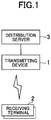
- FIG. 1 is a diagram illustrating an example of a wireless communication system according to the present embodiment.
- the wireless communication system includes a transmitting device 1, one or more receiving terminals 2, and a distribution server 3.
- the transmitting device 1 is a wireless LAN access point, for example, and is a form of a wireless transmitting device capable of transmitting a plurality of frames in accordance with IEEE802 11.
- the frames include a plurality of broadcast frames.
- a wireless communication system that is effective when broadcast transmission is wirelessly performed will be described below.
- Each of one or more receiving terminals 2 includes a wireless LAN client.
- the receiving terminal 2 is, for example, a personal computer or a smartphone, and can communicate with the wireless LAN access point in accordance with IEEE802 11.
- the receiving terminal 2 is a form of a wireless receiving device.
- the distribution server 3 stores transmission data to be transmitted by broadcast in a data source, and delivers the transmission data to the transmitting device 1.
- the transmitting device 1 mainly transmits data
- the receiving terminal 2 receives the data, although the transmitting device 1 may receive the data, and the receiving terminal 2 may transmit the data.
- FIG. 2 is a schematic diagram illustrating relationship between modulation methods and distributable areas.
- FIG. 2 shows the distributable areas R0, R5, and R11 when the transmitting device 1 transmits frames using the modulating methods MCS0, MCS5, and MCS11, respectively.
- MCS is an abbreviation for Modulation and Coding Scheme and defined by IEEE802.11.
- the distances between the transmitting device 1 and the edges of the distributable areas R0, R5, and R11 are about 100m, 50m, and 10m, respectively. When the transmission rate by the modulation method is higher, the distributable area becomes narrower.
- the receiving terminal 2a within the distributable area R11 can receive and demodulate the frame modulated by the MCS11, and can also receive and demodulate the frame modulated by other modulation methods.
- the receiving terminal 2b which is outside the distributable area R11 and within the distributable area R5, is unable to receive the frame modulated by the MCS11, but can receive and demodulate the frame modulated by the MCS5 and the MCS0.
- the receiving terminal 2c outside the distributable area R5 and within the distributable area R0 cannot receive the frame modulated by the MCSs 11 and 5, but can receive and demodulate the frame modulated by the MCS0.
- the modulation method that enables the receiving terminal 2 to receive data may differ depending on the environment in which the receiving terminal 2 is located.
- some receiving terminals 2 cannot receive data.
- the receiving terminal 2a near the transmitting device 1 takes longer to receive the broadcast frame than when receiving the broadcast frame with its original performance, for example.
- the configuration for more efficient broadcast transmission will be described in more detail.
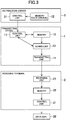
- FIG. 3 is a block diagram showing an example of the configurations of the transmitting device 1, the receiving terminal 2, and the distribution server 3.
- the transmitting device 1 includes a control unit 11, a memory 12, a scheduler 13, and a transmitting unit 14.
- the receiving terminal 2 includes a control unit 21, a memory 22, and a receiving unit 23.
- the distribution server 3 includes a control unit 31 and a memory 32.
- FIG. 14 is a block diagram showing an example of a hardware configuration of the transmitting device 1, the receiving terminal 2, and the distribution server 3, and programs stored in the memories 12 and 22.
- the control units 11, 21, and 31 respectively include at least one processor 110, 210, and 310, and respectively include communication units 111, 211, and 311, which are hardware for wired communication interfaces.
- the processors 110, 210, and 310 respectively included in the control units 11, 21, and 31 execute processing based on the programs respectively stored in the memories 12, 22, and 32.
- the control units 11, 21, and 31 may execute processing by dedicated hardware instead of at least some of the programs.
- the memories 12, 22, and 32 include, for example, a volatile memory and a nonvolatile memory.
- the memory 12 of the transmitting device 1 can store the transmission data to be transmitted, and the memory 22 of the receiving terminal 2 can store the received data.
- the memory 32 of the distribution server 3 is also a data source and stores data to be transmitted.
- the memory 12 stores programs of an acquisition module 51, a control module 52, a scheduler module 53, and a compression module 55.
- the processor 110 may execute processing of the scheduler 13 by executing the scheduler module 53.
- the memory 22 stores the program of the control module 61.
- the memory 32 may store the program of the compression module 55.
- the scheduler 13 reads the transmission data stored in the memory 12 under the control of the control unit 11 and delivers the read data to the transmitting unit 14.
- the transmitting unit 14 sequentially transmits a plurality of frames by wireless broadcasting. Each frame has a part of the transmission data. More specifically, the transmission data is internally divided into a plurality of sub-data pieces according to a size that can be stored in the frame, and each of the plurality of frames includes any of the sub-data pieces.
- the scheduler 13 reads the sub-data piece to be transmitted next from the memory 12, and delivers the data of the frame including the sub-data piece to the transmitting unit 14.
- the scheduler 13 may be the same processor as the one included in control unit 11 or may be hardware optimized for data transfer.
- Transmitting unit 14 includes an antenna and a modulation circuit.
- the transmitting unit 14 modulates each of a plurality of frames by one of a plurality of modulation methods.
- the plurality of modulation methods are defined by IEEE802.11 standard and are called MCSs.
- IEEE802.11ax has MCS0 to MCS11, the higher the numerical value, the higher the transmission rate.
- the transmitting unit 14 may transmit the first frame modulated by the first modulation method, which is one of the plurality of modulation methods, based on one of the sub-data pieces (corresponding to a part of the transmission data), and then transmit the second frame modulated by the second modulation method, which is one of the modulation methods and is different from the first modulation method, based on the one of the sub-data pieces.
- the frames based on the same data are transmitted in a plurality of frames having different modulation methods.
- the frame by the modulation method with a high transmission rate is transmitted first.
- the receiving unit 23 includes an antenna and a demodulation circuit.
- the receiving unit 23 receives a plurality of frames transmitted by the transmitting unit 14.
- the receiving unit 23 receives the frames regardless of the modulation methods of the respective frames, although the receiving unit 23 may receive only some of the modulation methods depending on the radio wave intensity.
- the receiving unit 23 demodulates the received frame.
- the data included in the demodulated frame is stored in the memory 22.
- the receiving unit 23 of the receiving terminal 2 may receive frames including the same data (or data obtained by compressing the same data at different compression rates) for multiple times.
- the control unit 21 does not output duplicate data as a reception result.
- the control unit 21 outputs the data included in the first frame and discards the data included in the second frame by executing the program of the control module 61.
- a data sink 29 stores data output by the control unit 21.
- the data sink 29 may be the memory 22 or a storage included in the receiving terminal 2, or an external computer. Based on the data stored in the data sink 29, content such as video and audio or a message is output, for example.
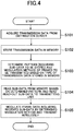
- FIG. 4 is a flow chart for explaining the processing of the transmitting device 1.
- the control unit 11 acquires the transmission data from the data source of the distribution server 3 by executing the program of the acquisition module 51 (step S101).
- the control unit 11 may acquire the transmission data by actively requesting the distribution server 3, or may acquire the transmission data by passively receiving the transmission data transmitted from the distribution server 3. Further, the control unit 11 may acquire the transmission data previously stored in the memory 12.
- the control unit 11 stores the acquired transmission data in the memory 12 by executing the program of the acquisition module 51 (step S102).
- the memory 12 stores transmission data to be transmitted.
- the transmission data is classified into various types.
- types of the transmission data include streaming data and downloaded data, for example.
- the streaming data is data that requires immediacy
- the downloaded data is data of application programs or content that does not require immediacy, for example.
- the control unit 11 determines a pattern of frames to be transmitted based on the type of the transmission data stored in the memory 12 by executing the program of the control module 52 (step S103).
- the pattern includes sub-data pieces to be respectively stored in the frames to be sequentially transmitted and the modulation method of each of the frames.
- the control unit 11 may select one of the plurality of patterns, or may constantly determine a predetermined pattern.
- the pattern may be an instruction defining an operation of the scheduler 13 and the transmitting unit 14.
- the pattern may be a modulation method of each of the frames transmitted in order, and information specifying a sub-data piece stored in each of the frames.
- the information for specifying the sub-data piece may be information indicating a change in positions of the sub data piece stored in the a-th frame (a is an integer of 1 or more and less than b, b is the number of sub-data pieces) transmitted by a certain modulation method and the sub-data piece stored in the (a+1)-th frame transmitted by such a modulation method.
- the scheduler 13 reads the sub-data piece from the memory 12 and sends the read-out sub-data piece to the transmitting unit 14 (step S104). Subsequently, the transmitting unit 14 modulates the frame data including the received sub-data piece using the modulation method determined as the pattern, and transmits the data wirelessly (step S105).
- the transmitting device 1 transmits data using a plurality of modulation methods in accordance with the pattern determined by the control unit 11. With the use of the pattern corresponding to characteristics of data and a communication environment, for example, it is possible to transmit data more appropriately.
- the control unit 11 controls the transmitting unit 14 to transmit the first frame modulated by the first modulation method, which is one of the plurality of modulation methods, based on one of the sub-data pieces (corresponding to a part of the transmission data), and then transmit the second frame modulated by the second modulation method, which is one of the modulation methods and is different from the first modulation method, based on the one of the sub-data pieces.
- the first modulation method has faster transmission rate than the second modulation method.
- m modulation methods i.e., three modulation methods of MCS11, MCS5, MCS0
- the m-th modulation method (MCS0 in this case) are defined in order of a transmission rate.
- FIG. 5 is a diagram illustrating an example of a plurality of frames to be transmitted.
- a rectangular area indicated as a frame represents a period during which the frame is transmitted, and a character string in the rectangle represents a modulation method.
- the reference symbols of the sub-data pieces below the rectangular areas of the frames are information indicating the positions of the sub-data pieces in the original transmitted data stored in the frames.
- the frames may respectively include the reference symbols as sub-data identification information.
- the sub-data identification information is used in the receiving terminal 2. If the transmission data is downloaded data, the transmitting unit 14 may transmit a frame including the sub-data identification information.
- the control unit 11 controls the transmitting unit 14 to repeat transmitting one frame of the first modulation method, one frame of the second modulation method,..., and one frame of the m-th modulation method in order, and regarding next piece of sub-data as well, transmitting a plurality of frames. More specifically, the control unit 11 controls the scheduler 13 to sequentially deliver the sub-data pieces from the memory 12 to the transmitting unit 14 based on the above-described pattern, and controls the transmitting unit 14 to transmit frames including the sub-data pieces sent by the modulation method corresponding to the pattern.
- the control unit 11 determines the pattern shown in FIG. 5 and controls the transmitting unit 14.
- FIG. 6 is a diagram illustrating an example of comparison between a plurality of frames to be transmitted.
- FIG. 6 is an example of transmission of frames in a conventional broadcast.
- the transmission rate is limited because broadcast data is transmitted only by the modulation method with the lowest transmission rate (MCS0 in this case).
- MCS0 the lowest transmission rate
- the same data is transmitted by the modulation method with a high transmission rate, and thus, the receiving terminal 2 close to the transmitting device 1 can reliably receive the data.
- the frame by the modulation method with a higher transmission rate is transmitted first, and thus the receiving terminal 2 close to the transmitting device 1 can receive the data earlier than a case where the data is transmitted in other orders.
- FIG. 7 is a diagram illustrating another example of a plurality of frames to be transmitted.
- the control unit 11 controls the transmitting unit 14 to repeat transmitting successive F(1) frames of the first modulation method, successive F(2) frames of the second modulation method,..., successive F(m) frames of the m-th modulation method in order.
- the condition of F(1)>F(2)>... >F(m) is satisfied.
- a plurality of frames transmitted by the same modulation method among all the frames transmitted by the transmitting unit 14 when a frame storing certain sub-data piece is transmitted, then a frame storing next sub-data piece is transmitted.
- the successive sub-data pieces are respectively stored in successive F(p) frames (p is an integer from 1 to m).
- the frame following the last frame shown in FIG. 7 including the eighth sub-data piece is modulated by the MCS11 and transmitted.
- data is transmitted in a shorter time in a modulation method with a high transmission rate. Accordingly, data of an application, for example, can be downloaded in a shorter time in the receiving terminal 2 close to the transmitting device 1. If the transmitting device 1 needs to transmit data in a short time by broadcast to a receiving terminal 2 close to the transmitting device 1 but may slowly transmit the data to a distant receiving terminal 2 (when a data type has high probability), the control unit 11 determines the pattern shown in FIG. 7 and controls the transmitting unit 14.
- FIG. 8 is a diagram illustrating another example of a plurality of frames to be transmitted.
- a plurality of frames transmitted by the same modulation method among all the frames transmitted by the transmitting unit 14 include two consecutive frames storing the same sub-data piece.
- the frames transmitted by the same modulation method include, after the two successive frames, another two successive frames storing the next sub-data piece.
- frames of a certain sub-data piece are sequentially transmitted multiple times, it is possible to more reliably receive data even if an error occurs at the time of reception.
- the control unit 11 determines the pattern shown in FIG. 8 and controls the transmitting unit 14.
- FIG. 9 is a diagram illustrating another example of a plurality of frames to be transmitted.
- a plurality of frames transmitted by the same modulation method among all the frames transmitted by the transmitting unit 14 include a plurality of sets each including two frames.
- Each set includes a frame in which k-th sub-data piece (k is an integer equal to or greater than 1 and less than n, n is an integer equal to or greater than 2) is stored, and a next frame in which (k+1)-th sub-data piece is stored.
- the k-th sub-data piece is modulated and transmitted by the first modulation method, and then the (k+1)-th sub-data piece is modulated and transmitted by the first modulation method.
- This processing is repeated (see MCS11 of FIG. 9 ), and after such repetition, the control unit 11 controls the transmitting unit 14 to transmit a frame in which the k-th sub-data is modulated by the second modulation method (see MCS5 of FIG. 9 ).
- the control unit 11 determines the pattern shown in FIG. 9 and controls the transmitting unit 14.
- FIG. 10 is a diagram illustrating another example of a plurality of frames to be transmitted.
- the transmitting unit 14 of the transmitting device 1 distributes video data by a plurality of modulation methods.
- the control unit 11 controls the transmitting unit 14 to transmit a first frame that includes a part of a first compressed data, in which the original transmission data is compressed, and is modulated by the first modulation method, and then transmit a second frame that includes second compressed data, in which the part of the transmission data is compressed in a different compression rate from the first compressed data, and is modulated by the second modulation method.
- the first compressed data and the second compressed data are generated by the processor 110 executing a program of the compression module 55 and thereby compressing at least a part of the transmitted data, and are stored in the memory 12.
- the first compressed data and the second compressed data may be generated by the processor 310 of the distribution server 3 executing a program of the compression module 55, and the transmitting device may acquire the first compressed data and the second compressed data and store the data in the memory 12.
- the sub-data pieces d1 and d2 are transmitted by the frames of the MCS11, the sub-data pieces d1a and d2a are transmitted by the frames of the MCS5, and the sub-data pieces d1b and d2b are transmitted by the frames of the MCS0.
- the sub-data pieces d1, dla, and d2a are based on the same sub-data piece, and the sub-data pieces d2, d2a, and d2b are based on the same data.
- the data compressed from the original data is divided into sub-data pieces stored in respective frames.
- the frames storing the compressed sub-data piece generated based on the same sub-data piece may include the same sub-data identification information.
- the ratio of the sub-data piece stored in the i-th modulation method to the sub-data piece before compression is defined as a compression ratio C (i) (i is an integer of 1 to m)
- the condition of 1 ⁇ C(1) > C(2) >...> C(m) is satisfied.
- the compression executed here is lossy compression.
- the control unit 11 controls the transmitting unit 14 to transmit a frame of a sub-data piece having a large compression ratio C(i), i.e., less compressed sub-data piece, before a frame of more compressed sub-data piece.
- the control unit 11 determines a pattern shown in FIG. 10 when sending data that requires real-time performance and can be lossy-compressed, such as video data, by broadcast.
- the control unit 11 has encoders for the video data, compresses and encodes the video data stored in the memory 12 at a compression ratio C(i) according to the i-th modulation method, and divides the data into sub-data pieces of appropriate sizes.
- the compressed encoding may be performed by the control unit 31 of the distribution server 3.
- the receiving terminal 2 close to the transmitting device 1 can output a high-quality image based on more amount of data.
- the transmitting unit 14 of the transmitting device 1 may transmit a mixture of broadcast frames and unicast frames.
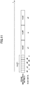
- FIG. 11 is a diagram illustrating an example of a plurality of frames to be transmitted. In the example of FIG. 11 , the transmitting unit 14 transmits a mixture of frames including unicast sub-data piece u and frames including broadcast sub-data pieces d1 to d6, x1, and x2.
- FIG. 12 is a flow chart for explaining the processing of the receiving terminal 2. The processing shown in FIG. 12 is executed each time the receiving unit 23 of the receiving terminal 2 receives a frame.
- the receiving unit 23 receives a frame transmitted from the transmitting unit 14, and demodulates frame data included in the frame (step S201).
- the receiving unit 23 stores a sub-data piece included in the demodulated frame data in the memory 22 (step S202).
- the receiving unit 23 may send the demodulated frame data to the control unit 21, and the control unit 21 may store the frame data in the memory 22.
- the control unit 21 outputs, to the data sink 29, only a sub-data piece that does not overlap with a previously received sub-data piece among the sub-data pieces demodulated by the transmitting unit 14. More specifically, among the sub-data pieces stored in the memory 22, the control unit 21 removes a sub-data piece that overlaps with a previously received sub-data piece (step S203). More specifically, if the sub-data identification information of the sub-data piece already received is the same as the sub-data identification information of the sub-data piece received thereafter, the control unit 21 may remove the sub-data piece received later as being overlapped.
- the control unit 21 outputs the sub-data piece that is not removed to the data sink 29 (step S204). If the data sink 29 is included in the receiving terminal 2 and used by the application program, the control unit 21 may store the sub-data piece in an area of the memory 22 accessed by the application program. If the data sink 29 is included in an external computer, the control unit 21 may transmit the sub-data piece to the external computer.
- the transmitting device 1 sequentially transmits the first frame in which the first compressed data in which a part of transmission data is compressed is modulated by the first modulation method and the second frame in which the second compressed data, a part of which is more compressed than the first compressed data, is modulated by the second modulation method.
- the control unit 21 When the receiving unit 23 receives the first frame and the second frame, the control unit 21 outputs, to the data sink 29, the first compressed data demodulated from the first frame that is received by the receiving unit 23 first, and does not output the second compressed data demodulated from the second frame. This enables the receiving terminal 2 in a better reception environment to output more uncompressed data in a simpler form.
- the transmitting device 1 transmits the same data or the data based on the same data by a plurality of modulation methods.
- different pieces of data are modulated by a plurality of modulation methods and transmitted by broadcast.
- the transmitting device 1 also includes the control unit 11, the memory 12, the scheduler 13, and the transmitting unit 14, and thus the descriptions thereof are omitted.
- the configuration of the receiving terminal 2 is not greatly different from the first embodiment, and thus the description thereof will be omitted.
- control unit 11 acquires the first transmission data from the distribution server 3 and the second transmission data that is different from the first transmission data, and stores the acquired data in the memory 12.
- control unit 11 controls such that a plurality of frames transmitted by the transmitting unit 14 include a plurality of first frames in which the first transmission data is modulated by the first modulation method and a plurality of second frames in which the second transmission data is modulated by the second modulation method.
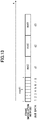
- FIG. 13 is a diagram illustrating an example of a plurality of frames to be transmitted in the second embodiment.
- the example of FIG. 13 shows sub-data pieces 1 to 8 of the first transmission data transmitted by the MCS11, which is a modulation method with a high transmission rate, and sub-data pieces d1 to d3 of the second transmission data subsequently transmitted by the MCS0, which is a modulation method with a low transmission rate.
- the first data may be video content introducing exhibits in the vicinity of the transmitting device 1
- the second data may be data of text content introducing exhibits in the vicinity of the transmitting device 1.
- the modulation methods are varied according to the characteristic of the data to be transmitted by broadcast, which serves to transmit data more efficiently.
Landscapes
- Engineering & Computer Science (AREA)
- Computer Networks & Wireless Communication (AREA)
- Signal Processing (AREA)
- Quality & Reliability (AREA)
- Mobile Radio Communication Systems (AREA)
- Detection And Prevention Of Errors In Transmission (AREA)
Abstract
Description
- The present invention relates to a wireless transmitting device, a wireless receiving device, and a wireless transmitting method.
- Wireless LANs are used in various locations. In wireless LAN communication, broadcast packets including SSID and ARP are transmitted through a wireless LAN access point. The broadcast packets are sent to all wireless LAN clients. As such, data to be broadcast is generally modulated by a modulation method having the lowest transmission rate among a plurality of modulation methods defined in advance (referred to as MCSs), and transmitted to a wireless LAN client.
-
JP2018-514752A - With the diversification of network services, transmitting various types of content by broadcast is considered. At present, it is difficult to transmit a large amount of data in a short time by a modulation method with a low transmission rate, and a modulation method with a high transmission rate is likely to result in a case where a client cannot receive data.
- One or more embodiments of the present invention have been conceived in view of the above, and an object thereof is to provide a technique that enables more appropriate data transmission through wireless LAN broadcast.
- In order to solve the above described problems, a wireless transmitting device according to one embodiment of the present invention includes an acquiring unit configured to acquire transmission data; a transmitting unit configured to sequentially transmit, by broadcast, a plurality of frames contained in the acquired transmission data, that are modulated by any of a plurality of modulation and coding schemes (MCSs), including a first MCS and a second MCS; and a control unit configured to control the transmitting unit to transmit a first frame that is modulated by the first MCS based on the acquired transmission data and then to transmit a second frame that is modulated by the second MCS based on the acquired transmission data.
- A wireless transmitting method according to one embodiment of the present invention includes acquiring transmission data; sequentially transmitting, by broadcast, a plurality of frames contained in the acquired transmission data, that are modulated by any of a plurality of modulation and coding schemes (MCSs), including a first MCS and a second MCS; and controlling to transmit a first frame that is modulated by the first MCS based on the acquired transmission data and then to transmit a second frame that is modulated by the second MCS based on the acquired transmission data.
- A wireless receiving device according to one embodiment of the present invention includes a receiving unit configured to receive a plurality of frames that are sequentially transmitted by broadcast via a transmitting device and are modulated by any of a plurality of modulation and coding schemes (MCSs), including a first MCS and a second MCS based on transmission data acquired by the transmitting device; and a control unit configured to, in a case where the receiving unit receives a first frame, among the plurality of frames, that is modulated by the first MCS based on a part of the transmission data and subsequently receives a second frame, among the plurality of frames, that is modulated by the second MCS based on the part of the transmission data, output the first frame.
- A wireless system according to one embodiment of the present invention includes an acquiring unit configured to acquire transmission data; a transmitting unit configured to sequentially transmit, by broadcast, a plurality of frames contained in the acquired transmission data, that are modulated by any of a plurality of modulation and coding schemes (MCSs), including a first MCS and a second MCS; a receiving unit configured to receive the plurality of frames that are sequentially transmitted by the transmitting unit; a data acquiring unit; and a control unit configured to control the transmitting unit to transmit a first frame, among the plurality of frames, that is modulated by the first MCS based on the acquired transmission data and then to transmit a second frame, among the plurality of frames, that is modulated by the second modulation method based on the acquired transmission data, wherein in a case where the receiving unit receives the first frame and the second frame after the first frame, the data acquiring unit acquires the demodulated first frame and stores the acquired first frame in a storage unit.
- Another wireless transmitting device according to one embodiment of the present invention includes an acquiring unit configured to acquire first transmission data and second transmission data that is different from the first transmission data; a transmitting unit configured to sequentially transmit, by broadcast, a plurality of frames contained in the acquired transmission data, that are modulated by any of a plurality of modulation and coding schemes (MCSs) including a first MCS and a second MCS; and the control unit configured to control the transmitting unit such that the plurality of frames to be transmitted include a plurality of first frames in which the first transmission data is modulated by the first MCS and a plurality of second frames in which the second transmission data is modulated by the second MCS, and the second transmission data is different from the first transmission data.
- According to the present invention, data can be transmitted more appropriately through wireless LAN broadcast.
-
-
FIG. 1 is a diagram illustrating an example of a wireless communication system according to a first embodiment; -
FIG. 2 is a diagram illustrating relationship between modulation methods and distributable areas; -
FIG. 3 is a block diagram showing an example of configurations of the transmitting device and the receiving terminal; -
FIG. 4 is a flow chart for explaining processing of the transmitting device; -
FIG. 5 is a diagram illustrating an example of a plurality of frames to be transmitted; -
FIG. 6 is a diagram illustrating an example of comparison between a plurality of frames to be transmitted; -
FIG. 7 is a diagram illustrating another example of a plurality of frames to be transmitted; -
FIG. 8 is a diagram illustrating yet another example of a plurality of frames to be transmitted; -
FIG. 9 is a diagram illustrating yet another example of a plurality of frames to be transmitted; -
FIG. 10 is a diagram illustrating yet another example of a plurality of frames to be transmitted; -
FIG. 11 is a diagram illustrating an example of a plurality of frames to be transmitted; -
FIG. 12 is a flow chart for explaining processing of the receiving terminal; -
FIG. 13 is a diagram illustrating an example of a plurality of frames to be transmitted in a second embodiment; and -
FIG. 14 is a block diagram showing an example of hardware configurations of a transmitting device, a receiving terminal, and a distribution server, and programs stored in memories. - An embodiment of the present invention will be described below with reference to the accompanying drawings. In the present embodiment, a wireless communication system for transmitting and receiving a plurality of frames using a plurality of modulation methods in the same frequency band will be described. Unless otherwise stated, the wireless communication system transmits and receives data in accordance with IEEE802 11.
-
FIG. 1 is a diagram illustrating an example of a wireless communication system according to the present embodiment. The wireless communication system includes atransmitting device 1, one or more receivingterminals 2, and adistribution server 3. The transmittingdevice 1 is a wireless LAN access point, for example, and is a form of a wireless transmitting device capable of transmitting a plurality of frames in accordance with IEEE802 11. The frames include a plurality of broadcast frames. In particular, a wireless communication system that is effective when broadcast transmission is wirelessly performed will be described below. - Each of one or more receiving
terminals 2 includes a wireless LAN client. Thereceiving terminal 2 is, for example, a personal computer or a smartphone, and can communicate with the wireless LAN access point in accordance with IEEE802 11. Thereceiving terminal 2 is a form of a wireless receiving device. Thedistribution server 3 stores transmission data to be transmitted by broadcast in a data source, and delivers the transmission data to the transmittingdevice 1. Here, the transmittingdevice 1 mainly transmits data, and thereceiving terminal 2 receives the data, although the transmittingdevice 1 may receive the data, and thereceiving terminal 2 may transmit the data. -
FIG. 2 is a schematic diagram illustrating relationship between modulation methods and distributable areas.FIG. 2 shows the distributable areas R0, R5, and R11 when the transmittingdevice 1 transmits frames using the modulating methods MCS0, MCS5, and MCS11, respectively. MCS is an abbreviation for Modulation and Coding Scheme and defined by IEEE802.11. The distances between the transmittingdevice 1 and the edges of the distributable areas R0, R5, and R11 are about 100m, 50m, and 10m, respectively. When the transmission rate by the modulation method is higher, the distributable area becomes narrower. - The
receiving terminal 2a within the distributable area R11 can receive and demodulate the frame modulated by the MCS11, and can also receive and demodulate the frame modulated by other modulation methods. On the other hand, thereceiving terminal 2b, which is outside the distributable area R11 and within the distributable area R5, is unable to receive the frame modulated by the MCS11, but can receive and demodulate the frame modulated by the MCS5 and the MCS0. Thereceiving terminal 2c outside the distributable area R5 and within the distributable area R0 cannot receive the frame modulated by theMCSs receiving terminal 2 to receive data may differ depending on the environment in which thereceiving terminal 2 is located. - As shown in
FIG. 2 , depending on the modulation method, some receivingterminals 2 cannot receive data. On the other hand, if only a frame of a modulation method with a low transmission rate is used so that as many receivingterminals 2 as possible can receive a broadcast frame, thereceiving terminal 2a near the transmittingdevice 1 takes longer to receive the broadcast frame than when receiving the broadcast frame with its original performance, for example. In the following, the configuration for more efficient broadcast transmission will be described in more detail. -
FIG. 3 is a block diagram showing an example of the configurations of thetransmitting device 1, thereceiving terminal 2, and thedistribution server 3. The transmittingdevice 1 includes acontrol unit 11, amemory 12, ascheduler 13, and a transmittingunit 14. Thereceiving terminal 2 includes acontrol unit 21, amemory 22, and areceiving unit 23. Thedistribution server 3 includes acontrol unit 31 and amemory 32.FIG. 14 is a block diagram showing an example of a hardware configuration of the transmittingdevice 1, the receivingterminal 2, and thedistribution server 3, and programs stored in thememories - The
control units processor communication units - The
processors control units memories control units - The
memories memory 12 of the transmittingdevice 1 can store the transmission data to be transmitted, and thememory 22 of the receivingterminal 2 can store the received data. Thememory 32 of thedistribution server 3 is also a data source and stores data to be transmitted. Thememory 12 stores programs of anacquisition module 51, acontrol module 52, ascheduler module 53, and acompression module 55. Theprocessor 110 may execute processing of thescheduler 13 by executing thescheduler module 53. Thememory 22 stores the program of thecontrol module 61. Thememory 32 may store the program of thecompression module 55. - The
scheduler 13 reads the transmission data stored in thememory 12 under the control of thecontrol unit 11 and delivers the read data to the transmittingunit 14. The transmittingunit 14 sequentially transmits a plurality of frames by wireless broadcasting. Each frame has a part of the transmission data. More specifically, the transmission data is internally divided into a plurality of sub-data pieces according to a size that can be stored in the frame, and each of the plurality of frames includes any of the sub-data pieces. Thescheduler 13 reads the sub-data piece to be transmitted next from thememory 12, and delivers the data of the frame including the sub-data piece to the transmittingunit 14. Thescheduler 13 may be the same processor as the one included incontrol unit 11 or may be hardware optimized for data transfer. - Transmitting
unit 14 includes an antenna and a modulation circuit. The transmittingunit 14 modulates each of a plurality of frames by one of a plurality of modulation methods. The plurality of modulation methods are defined by IEEE802.11 standard and are called MCSs. For example, IEEE802.11ax has MCS0 to MCS11, the higher the numerical value, the higher the transmission rate. - In the present embodiment, the transmitting
unit 14 may transmit the first frame modulated by the first modulation method, which is one of the plurality of modulation methods, based on one of the sub-data pieces (corresponding to a part of the transmission data), and then transmit the second frame modulated by the second modulation method, which is one of the modulation methods and is different from the first modulation method, based on the one of the sub-data pieces. By this transmission, the frames based on the same data are transmitted in a plurality of frames having different modulation methods. For the same sub-data piece, the frame by the modulation method with a high transmission rate is transmitted first. - The receiving
unit 23 includes an antenna and a demodulation circuit. The receivingunit 23 receives a plurality of frames transmitted by the transmittingunit 14. The receivingunit 23 receives the frames regardless of the modulation methods of the respective frames, although the receivingunit 23 may receive only some of the modulation methods depending on the radio wave intensity. The receivingunit 23 demodulates the received frame. The data included in the demodulated frame is stored in thememory 22. - The receiving
unit 23 of the receivingterminal 2 may receive frames including the same data (or data obtained by compressing the same data at different compression rates) for multiple times. In this case, thecontrol unit 21 does not output duplicate data as a reception result. For example, in a case where the receivingunit 23 receives the first frame modulated by the first modulation method based on a part of the transmitted data, and then receives the second frame modulated by the second modulation method based on the part of the transmitted data, thecontrol unit 21 outputs the data included in the first frame and discards the data included in the second frame by executing the program of thecontrol module 61. - A data sink 29 stores data output by the
control unit 21. The data sink 29 may be thememory 22 or a storage included in the receivingterminal 2, or an external computer. Based on the data stored in the data sink 29, content such as video and audio or a message is output, for example. - Next, the processing when the transmitting
device 1 transmits the frame will be described in more detail.FIG. 4 is a flow chart for explaining the processing of the transmittingdevice 1. Thecontrol unit 11 acquires the transmission data from the data source of thedistribution server 3 by executing the program of the acquisition module 51 (step S101). Here, thecontrol unit 11 may acquire the transmission data by actively requesting thedistribution server 3, or may acquire the transmission data by passively receiving the transmission data transmitted from thedistribution server 3. Further, thecontrol unit 11 may acquire the transmission data previously stored in thememory 12. - The
control unit 11 stores the acquired transmission data in thememory 12 by executing the program of the acquisition module 51 (step S102). Thememory 12 stores transmission data to be transmitted. - The transmission data is classified into various types. For example, types of the transmission data include streaming data and downloaded data, for example. The streaming data is data that requires immediacy, and the downloaded data is data of application programs or content that does not require immediacy, for example.
- The
control unit 11 determines a pattern of frames to be transmitted based on the type of the transmission data stored in thememory 12 by executing the program of the control module 52 (step S103). The pattern includes sub-data pieces to be respectively stored in the frames to be sequentially transmitted and the modulation method of each of the frames. In the case of broadcasting, thecontrol unit 11 may select one of the plurality of patterns, or may constantly determine a predetermined pattern. - The pattern may be an instruction defining an operation of the
scheduler 13 and the transmittingunit 14. For example, the pattern may be a modulation method of each of the frames transmitted in order, and information specifying a sub-data piece stored in each of the frames. Further, the information for specifying the sub-data piece may be information indicating a change in positions of the sub data piece stored in the a-th frame (a is an integer of 1 or more and less than b, b is the number of sub-data pieces) transmitted by a certain modulation method and the sub-data piece stored in the (a+1)-th frame transmitted by such a modulation method. - Based on the determined pattern, the
scheduler 13 reads the sub-data piece from thememory 12 and sends the read-out sub-data piece to the transmitting unit 14 (step S104). Subsequently, the transmittingunit 14 modulates the frame data including the received sub-data piece using the modulation method determined as the pattern, and transmits the data wirelessly (step S105). - The transmitting
device 1 transmits data using a plurality of modulation methods in accordance with the pattern determined by thecontrol unit 11. With the use of the pattern corresponding to characteristics of data and a communication environment, for example, it is possible to transmit data more appropriately. - In the following, the pattern will be described in more detail. In the present embodiment, the
control unit 11 controls the transmittingunit 14 to transmit the first frame modulated by the first modulation method, which is one of the plurality of modulation methods, based on one of the sub-data pieces (corresponding to a part of the transmission data), and then transmit the second frame modulated by the second modulation method, which is one of the modulation methods and is different from the first modulation method, based on the one of the sub-data pieces. Further, the first modulation method has faster transmission rate than the second modulation method. - In the following, a case where m modulation methods (i.e., three modulation methods of MCS11, MCS5, MCS0) are used will be described. The first modulation method (MCS11 in this case), the second modulation method (MCS5 in this case), and the m-th modulation method (MCS0 in this case) are defined in order of a transmission rate.
-
FIG. 5 is a diagram illustrating an example of a plurality of frames to be transmitted. InFIG. 5 , a rectangular area indicated as a frame represents a period during which the frame is transmitted, and a character string in the rectangle represents a modulation method. The reference symbols of the sub-data pieces below the rectangular areas of the frames are information indicating the positions of the sub-data pieces in the original transmitted data stored in the frames. The frames may respectively include the reference symbols as sub-data identification information. The sub-data identification information is used in the receivingterminal 2. If the transmission data is downloaded data, the transmittingunit 14 may transmit a frame including the sub-data identification information. - In the pattern shown in
FIG. 5 , regarding a certain sub-data piece, thecontrol unit 11 controls the transmittingunit 14 to repeat transmitting one frame of the first modulation method, one frame of the second modulation method,..., and one frame of the m-th modulation method in order, and regarding next piece of sub-data as well, transmitting a plurality of frames. More specifically, thecontrol unit 11 controls thescheduler 13 to sequentially deliver the sub-data pieces from thememory 12 to the transmittingunit 14 based on the above-described pattern, and controls the transmittingunit 14 to transmit frames including the sub-data pieces sent by the modulation method corresponding to the pattern. - If the transmitting
device 1 needs to reliably transmit data by broadcast to a receivingterminal 2 close to the transmittingdevice 1 but needs not to reliably transmit the data to a distant receiving terminal 2 (when a data type has high probability), thecontrol unit 11 determines the pattern shown inFIG. 5 and controls the transmittingunit 14. -
FIG. 6 is a diagram illustrating an example of comparison between a plurality of frames to be transmitted.FIG. 6 is an example of transmission of frames in a conventional broadcast. In the example ofFIG. 6 , the transmission rate is limited because broadcast data is transmitted only by the modulation method with the lowest transmission rate (MCS0 in this case). As such, compared with the example ofFIG. 5 , if a reception error occurs in the receivingterminal 2 close to the transmittingdevice 1, it is necessary to wait for a long time until the reception of the data fails or the data is transmitted again. In the example ofFIG. 5 , the same data is transmitted by the modulation method with a high transmission rate, and thus, the receivingterminal 2 close to the transmittingdevice 1 can reliably receive the data. Further, in the example ofFIG. 5 , for the same sub-data piece, the frame by the modulation method with a higher transmission rate is transmitted first, and thus the receivingterminal 2 close to the transmittingdevice 1 can receive the data earlier than a case where the data is transmitted in other orders. -
FIG. 7 is a diagram illustrating another example of a plurality of frames to be transmitted. In the pattern shown inFIG. 7 , thecontrol unit 11 controls the transmittingunit 14 to repeat transmitting successive F(1) frames of the first modulation method, successive F(2) frames of the second modulation method,..., successive F(m) frames of the m-th modulation method in order. Here, the condition of F(1)>F(2)>... >F(m) is satisfied. Regarding a plurality of frames transmitted by the same modulation method among all the frames transmitted by the transmittingunit 14, when a frame storing certain sub-data piece is transmitted, then a frame storing next sub-data piece is transmitted. The successive sub-data pieces are respectively stored in successive F(p) frames (p is an integer from 1 to m). The frame following the last frame shown inFIG. 7 including the eighth sub-data piece is modulated by the MCS11 and transmitted. - In the example of
FIG. 7 , data is transmitted in a shorter time in a modulation method with a high transmission rate. Accordingly, data of an application, for example, can be downloaded in a shorter time in the receivingterminal 2 close to the transmittingdevice 1. If the transmittingdevice 1 needs to transmit data in a short time by broadcast to a receivingterminal 2 close to the transmittingdevice 1 but may slowly transmit the data to a distant receiving terminal 2 (when a data type has high probability), thecontrol unit 11 determines the pattern shown inFIG. 7 and controls the transmittingunit 14. -
FIG. 8 is a diagram illustrating another example of a plurality of frames to be transmitted. In the pattern shown inFIG. 8 , unlike the example ofFIG. 7 , a plurality of frames transmitted by the same modulation method among all the frames transmitted by the transmittingunit 14 include two consecutive frames storing the same sub-data piece. Further, the frames transmitted by the same modulation method include, after the two successive frames, another two successive frames storing the next sub-data piece. In the example ofFIG. 8 , frames of a certain sub-data piece are sequentially transmitted multiple times, it is possible to more reliably receive data even if an error occurs at the time of reception. If the transmittingdevice 1 needs to reliably transmit data to a receivingterminal 2 and also needs to send such data by broadcast in a short time to a receivingterminal 2 close to the transmitting device 1 (when a data type has high probability), thecontrol unit 11 determines the pattern shown inFIG. 8 and controls the transmittingunit 14. -
FIG. 9 is a diagram illustrating another example of a plurality of frames to be transmitted. In the pattern shown inFIG. 9 , unlike the example ofFIG. 7 , a plurality of frames transmitted by the same modulation method among all the frames transmitted by the transmittingunit 14 include a plurality of sets each including two frames. Each set includes a frame in which k-th sub-data piece (k is an integer equal to or greater than 1 and less than n, n is an integer equal to or greater than 2) is stored, and a next frame in which (k+1)-th sub-data piece is stored. In this case, the k-th sub-data piece is modulated and transmitted by the first modulation method, and then the (k+1)-th sub-data piece is modulated and transmitted by the first modulation method. This processing is repeated (see MCS11 ofFIG. 9 ), and after such repetition, thecontrol unit 11 controls the transmittingunit 14 to transmit a frame in which the k-th sub-data is modulated by the second modulation method (see MCS5 ofFIG. 9 ). In the example ofFIG. 9 as well, similarly to the example ofFIG. 8 , it is possible to secure efficiency while more reliably receiving data. In the same case as inFIG. 8 , thecontrol unit 11 determines the pattern shown inFIG. 9 and controls the transmittingunit 14. -
FIG. 10 is a diagram illustrating another example of a plurality of frames to be transmitted. In the example ofFIG. 10 , the transmittingunit 14 of the transmittingdevice 1 distributes video data by a plurality of modulation methods. Thecontrol unit 11 controls the transmittingunit 14 to transmit a first frame that includes a part of a first compressed data, in which the original transmission data is compressed, and is modulated by the first modulation method, and then transmit a second frame that includes second compressed data, in which the part of the transmission data is compressed in a different compression rate from the first compressed data, and is modulated by the second modulation method. Here, the first compressed data and the second compressed data are generated by theprocessor 110 executing a program of thecompression module 55 and thereby compressing at least a part of the transmitted data, and are stored in thememory 12. The first compressed data and the second compressed data may be generated by theprocessor 310 of thedistribution server 3 executing a program of thecompression module 55, and the transmitting device may acquire the first compressed data and the second compressed data and store the data in thememory 12. - More specifically, in the example of
FIG. 10 , the sub-data pieces d1 and d2 are transmitted by the frames of the MCS11, the sub-data pieces d1a and d2a are transmitted by the frames of the MCS5, and the sub-data pieces d1b and d2b are transmitted by the frames of the MCS0. The sub-data pieces d1, dla, and d2a are based on the same sub-data piece, and the sub-data pieces d2, d2a, and d2b are based on the same data. The data compressed from the original data is divided into sub-data pieces stored in respective frames. The frames storing the compressed sub-data piece generated based on the same sub-data piece may include the same sub-data identification information. - If the ratio of the sub-data piece stored in the i-th modulation method to the sub-data piece before compression is defined as a compression ratio C (i) (i is an integer of 1 to m), the condition of 1≧C(1) > C(2) >...> C(m) is satisfied. In other words, when a frame of a modulation method has a slower transmission rate, data is more compressed. The compression executed here is lossy compression. Regarding a plurality of sub-data pieces in which equivalent parts of the original data are compressed, the
control unit 11 controls the transmittingunit 14 to transmit a frame of a sub-data piece having a large compression ratio C(i), i.e., less compressed sub-data piece, before a frame of more compressed sub-data piece. - The
control unit 11 determines a pattern shown inFIG. 10 when sending data that requires real-time performance and can be lossy-compressed, such as video data, by broadcast. In this pattern, thecontrol unit 11 has encoders for the video data, compresses and encodes the video data stored in thememory 12 at a compression ratio C(i) according to the i-th modulation method, and divides the data into sub-data pieces of appropriate sizes. The compressed encoding may be performed by thecontrol unit 31 of thedistribution server 3. - As a result, for example, when the video data is transmitted by broadcast, the receiving
terminal 2 close to the transmittingdevice 1 can output a high-quality image based on more amount of data. - The transmitting
unit 14 of the transmittingdevice 1 may transmit a mixture of broadcast frames and unicast frames.FIG. 11 is a diagram illustrating an example of a plurality of frames to be transmitted. In the example ofFIG. 11 , the transmittingunit 14 transmits a mixture of frames including unicast sub-data piece u and frames including broadcast sub-data pieces d1 to d6, x1, and x2. - Next, the processing when the receiving
terminal 2 receives a frame will be described in more detail.FIG. 12 is a flow chart for explaining the processing of the receivingterminal 2. The processing shown inFIG. 12 is executed each time the receivingunit 23 of the receivingterminal 2 receives a frame. - The receiving
unit 23 receives a frame transmitted from the transmittingunit 14, and demodulates frame data included in the frame (step S201). The receivingunit 23 stores a sub-data piece included in the demodulated frame data in the memory 22 (step S202). Here, the receivingunit 23 may send the demodulated frame data to thecontrol unit 21, and thecontrol unit 21 may store the frame data in thememory 22. - The
control unit 21 outputs, to the data sink 29, only a sub-data piece that does not overlap with a previously received sub-data piece among the sub-data pieces demodulated by the transmittingunit 14. More specifically, among the sub-data pieces stored in thememory 22, thecontrol unit 21 removes a sub-data piece that overlaps with a previously received sub-data piece (step S203). More specifically, if the sub-data identification information of the sub-data piece already received is the same as the sub-data identification information of the sub-data piece received thereafter, thecontrol unit 21 may remove the sub-data piece received later as being overlapped. - The
control unit 21 outputs the sub-data piece that is not removed to the data sink 29 (step S204). If the data sink 29 is included in the receivingterminal 2 and used by the application program, thecontrol unit 21 may store the sub-data piece in an area of thememory 22 accessed by the application program. If the data sink 29 is included in an external computer, thecontrol unit 21 may transmit the sub-data piece to the external computer. - In the example of
FIG. 10 , if the parts of the data before compression substantially overlap, the sub-data identification information is the same even if the compression ratios are different, and the more uncompressed sub-data piece is sent first. Specifically, the transmittingdevice 1 sequentially transmits the first frame in which the first compressed data in which a part of transmission data is compressed is modulated by the first modulation method and the second frame in which the second compressed data, a part of which is more compressed than the first compressed data, is modulated by the second modulation method. When the receivingunit 23 receives the first frame and the second frame, thecontrol unit 21 outputs, to the data sink 29, the first compressed data demodulated from the first frame that is received by the receivingunit 23 first, and does not output the second compressed data demodulated from the second frame. This enables the receivingterminal 2 in a better reception environment to output more uncompressed data in a simpler form. - In the first embodiment, the transmitting
device 1 transmits the same data or the data based on the same data by a plurality of modulation methods. In the second embodiment, different pieces of data are modulated by a plurality of modulation methods and transmitted by broadcast. In the following, differences from the first embodiment will be mainly described. The transmittingdevice 1 also includes thecontrol unit 11, thememory 12, thescheduler 13, and the transmittingunit 14, and thus the descriptions thereof are omitted. In addition, the configuration of the receivingterminal 2 is not greatly different from the first embodiment, and thus the description thereof will be omitted. - In the second embodiment, the
control unit 11 acquires the first transmission data from thedistribution server 3 and the second transmission data that is different from the first transmission data, and stores the acquired data in thememory 12. - Further, the
control unit 11 controls such that a plurality of frames transmitted by the transmittingunit 14 include a plurality of first frames in which the first transmission data is modulated by the first modulation method and a plurality of second frames in which the second transmission data is modulated by the second modulation method. -
FIG. 13 is a diagram illustrating an example of a plurality of frames to be transmitted in the second embodiment. The example ofFIG. 13 showssub-data pieces 1 to 8 of the first transmission data transmitted by the MCS11, which is a modulation method with a high transmission rate, and sub-data pieces d1 to d3 of the second transmission data subsequently transmitted by the MCS0, which is a modulation method with a low transmission rate. For example, if the transmittingdevice 1 is located in a museum, the first data may be video content introducing exhibits in the vicinity of the transmittingdevice 1, and the second data may be data of text content introducing exhibits in the vicinity of the transmittingdevice 1. The modulation methods are varied according to the characteristic of the data to be transmitted by broadcast, which serves to transmit data more efficiently.
Claims (15)
- A wireless transmitting device comprising:an acquiring unit configured to acquire transmission data;a transmitting unit configured to sequentially transmit, by broadcast, a plurality of frames contained in the acquired transmission data, that are modulated by any of a plurality of modulation and coding schemes (MCSs), including a first MCS and a second MCS; anda control unit configured to control the transmitting unit to transmit a first frame that is modulated by the first MCS based on the acquired transmission data and then to transmit a second frame that is modulated by the second MCS based on the acquired transmission data.
- The wireless transmitting device according to claim 1, wherein
each of the plurality of MCSs is defined in IEEE802.11. - The wireless transmitting device according to claim 1, wherein
the transmission data is divided into a plurality of sub-data pieces,
the first frame includes a first sub-data piece, among the plurality of sub-data pieces, and
the second frame includes a second sub-data piece, among the plurality of sub-data pieces. - The wireless transmitting device according to claim 3, wherein
a transmission rate of the first MCS is faster than a transmission rate of the second MCS. - The wireless transmitting device according to claim 3 or 4, wherein
the control unit controls the transmitting unit to transmit, after transmitting the first frame, a third frame including a second sub-data piece that follows the first sub-data piece, among the plurality of sub-data pieces, modulated by the first MCS, among the plurality of MCSs, following the transmitted first frame, before transmitting the second frame. - The wireless transmitting device according to claim 3 or 4, wherein
the control unit controls the transmitting unit to transmit, after transmitting the first frame, a fourth frame including the first sub-data piece, among the plurality of sub-data pieces modulated by the first MCS. - The wireless transmitting device according to claim 3 or 4, wherein
the control unit controls the transmitting unit to repeat transmitting a frame including a k-th sub-data piece, among the plurality of sub-data pieces, where k is an integer greater than or equal to 1 and less than n, which is an integer greater than or equal to 2, modulated by the first MCS;
then a frame including a (k+1)-th sub-data piece, among the plurality of sub-data pieces, modulated by the first MCS; and
then a frame including the k-th sub-data piece modulated by the second MCS. - The wireless transmitting device according to any one of claims 3 to 7, wherein
the plurality of frames each include information indicating a position of a corresponding sub-data piece, among the plurality of sub-data pieces, included therein. - The wireless transmitting device according to claim 8, wherein
the transmission data is either streaming data or downloaded data, and
in a case where the transmission data is downloaded data, the transmitting unit transmits a frame, among the plurality of sub-data pieces, including the information about the position of the corresponding sub-data piece. - The wireless transmitting device of claim 1, whereinthe first frame includes first compressed data included in the transmission data, andthe second frame includes second compressed data included in the transmission data, the second compressed data being compressed in a different compression rate from the first compressed data.
- The wireless transmitting device according to any one of claims 1 to 10, wherein
each of the first and second MCSs is defined by IEEE802.11. - A wireless receiving device comprising:a receiving unit configured to receive a plurality of frames that are sequentially transmitted by broadcast via a transmitting device and are modulated by any of a plurality of modulation and coding schemes (MCSs), including a first MCS and a second MCS based on transmission data acquired by the transmitting device; anda control unit configured to output the first frame after receiving the first frame modulated by the first MCS while not outputting the second frame after receiving the second frame modulated by the second MCS.
- The wireless receiving device according to claim 12, wherein
the first frame includes first compressed data included in the transmission data,
the second frame includes second compressed data included in the transmission data, the second compressed data being more compressed than the first compressed data, and
after the first frame and the second frame transmitted after the first frame are received, the control unit demodulates and output the first compressed data while not outputting the second compressed data. - A wireless system comprising:an acquiring unit configured to acquire transmission data;a transmitting unit configured to sequentially transmit, by broadcast, a plurality of frames contained in the acquired transmission data, that are modulated by any of a plurality of modulation and coding schemes (MCSs), including a first MCS and a second MCS;a receiving unit configured to receive the plurality of frames that are sequentially transmitted by the transmitting unit; anda data acquiring unit;a control unit configured to control the transmitting unit to transmit a first frame, among the plurality of frames, that is modulated by the first MCS based on the acquired transmission data and then to transmit a second frame, among the plurality of frames, that is modulated by the second MCS based on the acquired transmission data,wherein in a case where the receiving unit receives the first frame and the second frame after the first frame, the data acquiring unit acquires the demodulated first frame and stores the acquired first frame in a storage unit.
- A wireless transmitting method comprising:acquiring transmission data;sequentially transmitting, by broadcast, a plurality of frames contained in the acquired transmission data, that are modulated by any of a plurality of modulation and coding schemes (MCSs), including a first MCS and a second MCS; andcontrolling to transmit a first frame that is modulated by the first MCS based on the acquired transmission data and then to transmit a second frame that is modulated by the second modulation method based on the acquired transmission data.
Applications Claiming Priority (1)
| Application Number | Priority Date | Filing Date | Title |
|---|---|---|---|
| JP2019185505A JP7392374B2 (en) | 2019-10-08 | 2019-10-08 | Wireless transmitting device, wireless receiving device, wireless system, and wireless transmitting method |
Publications (1)
| Publication Number | Publication Date |
|---|---|
| EP3806362A1 true EP3806362A1 (en) | 2021-04-14 |
Family
ID=72752791
Family Applications (1)
| Application Number | Title | Priority Date | Filing Date |
|---|---|---|---|
| EP20200314.1A Pending EP3806362A1 (en) | 2019-10-08 | 2020-10-06 | Wireless transmitting device, wireless receiving device, and wireless transmitting method |
Country Status (4)
| Country | Link |
|---|---|
| US (1) | US11431437B2 (en) |
| EP (1) | EP3806362A1 (en) |
| JP (1) | JP7392374B2 (en) |
| CN (1) | CN112636778B (en) |
Citations (3)
| Publication number | Priority date | Publication date | Assignee | Title |
|---|---|---|---|---|
| JP2018514752A (en) | 2015-03-16 | 2018-06-07 | クアルコム,インコーポレイテッド | Position and distance determination using broadcast messages |
| US20190028671A1 (en) * | 2016-09-26 | 2019-01-24 | Samsung Display Co., Ltd. | System and method for electronic data communication |
| US20190182010A1 (en) * | 2017-12-08 | 2019-06-13 | Qualcomm Incorporated | Link adaptation enhancements |
Family Cites Families (22)
| Publication number | Priority date | Publication date | Assignee | Title |
|---|---|---|---|---|
| JPH1141310A (en) * | 1997-07-18 | 1999-02-12 | Matsushita Electric Ind Co Ltd | Communication method |
| US6590944B1 (en) * | 1999-02-24 | 2003-07-08 | Ibiquity Digital Corporation | Audio blend method and apparatus for AM and FM in band on channel digital audio broadcasting |
| JP2001285297A (en) | 2000-03-29 | 2001-10-12 | Hitachi Kokusai Electric Inc | Slave station device |
| JP3662473B2 (en) | 2000-05-12 | 2005-06-22 | 株式会社エヌ・ティ・ティ・ドコモ | Multicast service providing method and information distribution apparatus |
| JP2003348102A (en) | 2002-05-24 | 2003-12-05 | Hitachi Ltd | Server, and program for realizing information distribution method |
| CN101714909A (en) | 2004-01-28 | 2010-05-26 | 日本电气株式会社 | Content distribution method, encoding method, reception/reproduction method and device |
| JP2009290451A (en) | 2008-05-28 | 2009-12-10 | Kyocera Corp | Radio communication system, radio communication device, and radio communication method |
| JP4915458B2 (en) * | 2009-04-03 | 2012-04-11 | ソニー株式会社 | Information processing apparatus, information processing method, and program |
| US8817613B2 (en) * | 2009-05-01 | 2014-08-26 | Nec Corporation | Radio transmission apparatus and MAC frame transmission method |
| EP2740247A4 (en) | 2011-08-05 | 2015-03-25 | Intel Corp | Wireless communication device and method for multi-mcs ofdm transmissions at different transmission power levels |
| WO2013048484A1 (en) * | 2011-09-30 | 2013-04-04 | Intel Corporation | Quality of experience enhancements over wireless networks |
| US9706549B2 (en) | 2012-09-21 | 2017-07-11 | Mitsubishi Electric Corporation | Radio communication apparatus and radio communication system |
| EP3053386B1 (en) * | 2013-09-30 | 2019-02-13 | Apple Inc. | Delayed and bundled retransmissions for low bandwidth applications |
| JP2015082751A (en) | 2013-10-23 | 2015-04-27 | パナソニックIpマネジメント株式会社 | Transmission device, transmission method, and transmission program |
| US9654804B2 (en) * | 2014-09-03 | 2017-05-16 | Vigor Systems Inc. | Replacing video frames in a transport stream |
| JP6482653B2 (en) * | 2015-04-30 | 2019-03-13 | 株式会社東芝 | Wireless communication apparatus and wireless communication method |
| US10951935B2 (en) * | 2016-04-08 | 2021-03-16 | Source Digital, Inc. | Media environment driven content distribution platform |
| US20180006753A1 (en) * | 2016-07-01 | 2018-01-04 | Intel Corporation | Group addressed transmission techniques for directional wireless networks |
| JP6878224B2 (en) * | 2017-09-15 | 2021-05-26 | 株式会社東芝 | Wireless communication device and wireless communication method |
| US10992603B2 (en) * | 2017-09-27 | 2021-04-27 | Apple Inc. | Block acknowledgement with out-of-order packets |
| US10355810B1 (en) * | 2018-02-19 | 2019-07-16 | Wipro Limited | Method, device, and system for calibrating and adapting transmission rate in wireless communication |
| JP6967734B2 (en) | 2018-03-06 | 2021-11-17 | パナソニックIpマネジメント株式会社 | Communication equipment and wireless communication system |
-
2019
- 2019-10-08 JP JP2019185505A patent/JP7392374B2/en active Active
-
2020
- 2020-09-29 CN CN202011050922.5A patent/CN112636778B/en active Active
- 2020-10-06 EP EP20200314.1A patent/EP3806362A1/en active Pending
- 2020-10-06 US US17/064,078 patent/US11431437B2/en active Active
Patent Citations (3)
| Publication number | Priority date | Publication date | Assignee | Title |
|---|---|---|---|---|
| JP2018514752A (en) | 2015-03-16 | 2018-06-07 | クアルコム,インコーポレイテッド | Position and distance determination using broadcast messages |
| US20190028671A1 (en) * | 2016-09-26 | 2019-01-24 | Samsung Display Co., Ltd. | System and method for electronic data communication |
| US20190182010A1 (en) * | 2017-12-08 | 2019-06-13 | Qualcomm Incorporated | Link adaptation enhancements |
Non-Patent Citations (1)
| Title |
|---|
| MOBASHER AMIN ET AL: "Cross layer image optimization (CLIO) for wireless video transmission over 802.11ad multi-gigabit channels", 2017 IEEE INTERNATIONAL WORKSHOP TECHNICAL COMMITTEE ON COMMUNICATIONS QUALITY AND RELIABILITY (CQR), IEEE, 16 May 2017 (2017-05-16), pages 1 - 6, XP033318964, DOI: 10.1109/CQR.2017.8289447 * |
Also Published As
| Publication number | Publication date |
|---|---|
| US11431437B2 (en) | 2022-08-30 |
| CN112636778A (en) | 2021-04-09 |
| JP7392374B2 (en) | 2023-12-06 |
| CN112636778B (en) | 2022-07-08 |
| US20210105082A1 (en) | 2021-04-08 |
| JP2021061556A (en) | 2021-04-15 |
Similar Documents
| Publication | Publication Date | Title |
|---|---|---|
| US9143274B2 (en) | Traffic backfilling via network coding in a multi-packet reception network | |
| JP6965925B2 (en) | Base station equipment, terminal equipment, wireless communication systems, and communication methods | |
| CN104412665B (en) | System and method for dynamically configurable air interface | |
| US10122494B2 (en) | Systems and methods for providing resilience to LTE signaling interference in WiFi | |
| US7852826B2 (en) | Techniques to communication MAP information elements in a wireless network | |
| US20070286121A1 (en) | Systems and techniques for selective point-to-multipoint retransmission of multicast frames in a wireless network | |
| US10939252B2 (en) | Wireless communication apparatus, wireless communication method, and program for using a threshold to control multicast retransmission | |
| CN110663205B (en) | A data processing method and data processing device | |
| CN112713962B (en) | Communication method and device | |
| CN110289938B (en) | Multi-passive reflection label access system based on code division multiple access and control method | |
| WO2016172875A1 (en) | Information transmission method, network device and terminal device | |
| US20200067587A1 (en) | Information Processing Method and Device | |
| CN108365929B (en) | Method and device for transmitting data and method and device for transmitting information | |
| WO2018170877A1 (en) | Information sending method and apparatus, terminal, access network device and system | |
| CN109150378B (en) | A data processing method and data processing device | |
| US11431437B2 (en) | Wireless transmitting device, wireless receiving device, and wireless transmitting method | |
| CN107615810B (en) | Packet header compression system and method for online network code | |
| WO2022062426A1 (en) | Multicast scheduling method and apparatus for relay base station, storage medium and electronic device | |
| US9474066B2 (en) | Method and apparatus of transmitting and receiving system information in a wireless system | |
| CN116388833B (en) | Data transmission method, system and medium of Beidou No. three RDSS system | |
| EP3001744A1 (en) | Coverage enhancement for MBSFN transmission | |
| JP7435762B2 (en) | Wireless communication device and wireless communication method | |
| CN117335920A (en) | Encoding and decoding methods and related devices | |
| CN108366392A (en) | Accidental access method based on resource pattern | |
| CN113924756B (en) | Physical downlink control channel transmission method, device and storage medium |
Legal Events
| Date | Code | Title | Description |
|---|---|---|---|
| PUAI | Public reference made under article 153(3) epc to a published international application that has entered the european phase |
Free format text: ORIGINAL CODE: 0009012 |
|
| STAA | Information on the status of an ep patent application or granted ep patent |
Free format text: STATUS: THE APPLICATION HAS BEEN PUBLISHED |
|
| AK | Designated contracting states |
Kind code of ref document: A1 Designated state(s): AL AT BE BG CH CY CZ DE DK EE ES FI FR GB GR HR HU IE IS IT LI LT LU LV MC MK MT NL NO PL PT RO RS SE SI SK SM TR |
|
| AX | Request for extension of the european patent |
Extension state: BA ME |
|
| STAA | Information on the status of an ep patent application or granted ep patent |
Free format text: STATUS: REQUEST FOR EXAMINATION WAS MADE |
|
| 17P | Request for examination filed |
Effective date: 20210920 |
|
| RBV | Designated contracting states (corrected) |
Designated state(s): AL AT BE BG CH CY CZ DE DK EE ES FI FR GB GR HR HU IE IS IT LI LT LU LV MC MK MT NL NO PL PT RO RS SE SI SK SM TR |
|
| STAA | Information on the status of an ep patent application or granted ep patent |
Free format text: STATUS: EXAMINATION IS IN PROGRESS |
|
| 17Q | First examination report despatched |
Effective date: 20220923 |