EP3806283A1 - Method for determining charging region, electronic device and computer-readable medium - Google Patents
Method for determining charging region, electronic device and computer-readable medium Download PDFInfo
- Publication number
- EP3806283A1 EP3806283A1 EP20167889.3A EP20167889A EP3806283A1 EP 3806283 A1 EP3806283 A1 EP 3806283A1 EP 20167889 A EP20167889 A EP 20167889A EP 3806283 A1 EP3806283 A1 EP 3806283A1
- Authority
- EP
- European Patent Office
- Prior art keywords
- magnetic field
- point
- electronic device
- field intensity
- wireless charging
- Prior art date
- Legal status (The legal status is an assumption and is not a legal conclusion. Google has not performed a legal analysis and makes no representation as to the accuracy of the status listed.)
- Pending
Links
Images




Classifications
-
- H—ELECTRICITY
- H02—GENERATION; CONVERSION OR DISTRIBUTION OF ELECTRIC POWER
- H02J—ELECTRIC POWER NETWORKS; CIRCUIT ARRANGEMENTS OR SYSTEMS FOR SUPPLYING OR DISTRIBUTING ELECTRIC POWER; SYSTEMS FOR STORING ELECTRIC ENERGY
- H02J50/00—Circuit arrangements or systems for wireless supply or distribution of electric power
- H02J50/005—Mechanical details of housing or structure aiming to accommodate the power transfer means, e.g. mechanical integration of coils, antennas or transducers into emitting or receiving devices
-
- H—ELECTRICITY
- H02—GENERATION; CONVERSION OR DISTRIBUTION OF ELECTRIC POWER
- H02J—ELECTRIC POWER NETWORKS; CIRCUIT ARRANGEMENTS OR SYSTEMS FOR SUPPLYING OR DISTRIBUTING ELECTRIC POWER; SYSTEMS FOR STORING ELECTRIC ENERGY
- H02J50/00—Circuit arrangements or systems for wireless supply or distribution of electric power
- H02J50/10—Circuit arrangements or systems for wireless supply or distribution of electric power using inductive coupling
-
- H—ELECTRICITY
- H02—GENERATION; CONVERSION OR DISTRIBUTION OF ELECTRIC POWER
- H02J—ELECTRIC POWER NETWORKS; CIRCUIT ARRANGEMENTS OR SYSTEMS FOR SUPPLYING OR DISTRIBUTING ELECTRIC POWER; SYSTEMS FOR STORING ELECTRIC ENERGY
- H02J50/00—Circuit arrangements or systems for wireless supply or distribution of electric power
- H02J50/10—Circuit arrangements or systems for wireless supply or distribution of electric power using inductive coupling
- H02J50/12—Circuit arrangements or systems for wireless supply or distribution of electric power using inductive coupling of the resonant type
-
- H—ELECTRICITY
- H02—GENERATION; CONVERSION OR DISTRIBUTION OF ELECTRIC POWER
- H02J—ELECTRIC POWER NETWORKS; CIRCUIT ARRANGEMENTS OR SYSTEMS FOR SUPPLYING OR DISTRIBUTING ELECTRIC POWER; SYSTEMS FOR STORING ELECTRIC ENERGY
- H02J50/00—Circuit arrangements or systems for wireless supply or distribution of electric power
- H02J50/90—Circuit arrangements or systems for wireless supply or distribution of electric power involving detection or optimisation of position, e.g. alignment
-
- G—PHYSICS
- G01—MEASURING; TESTING
- G01R—MEASURING ELECTRIC VARIABLES; MEASURING MAGNETIC VARIABLES
- G01R33/00—Arrangements or instruments for measuring magnetic variables
-
- H—ELECTRICITY
- H04—ELECTRIC COMMUNICATION TECHNIQUE
- H04W—WIRELESS COMMUNICATION NETWORKS
- H04W4/00—Services specially adapted for wireless communication networks; Facilities therefor
- H04W4/02—Services making use of location information
- H04W4/021—Services related to particular areas, e.g. point of interest [POI] services, venue services or geofences
-
- H—ELECTRICITY
- H04—ELECTRIC COMMUNICATION TECHNIQUE
- H04W—WIRELESS COMMUNICATION NETWORKS
- H04W4/00—Services specially adapted for wireless communication networks; Facilities therefor
- H04W4/02—Services making use of location information
- H04W4/025—Services making use of location information using location based information parameters
- H04W4/026—Services making use of location information using location based information parameters using orientation information, e.g. compass
-
- Y—GENERAL TAGGING OF NEW TECHNOLOGICAL DEVELOPMENTS; GENERAL TAGGING OF CROSS-SECTIONAL TECHNOLOGIES SPANNING OVER SEVERAL SECTIONS OF THE IPC; TECHNICAL SUBJECTS COVERED BY FORMER USPC CROSS-REFERENCE ART COLLECTIONS [XRACs] AND DIGESTS
- Y02—TECHNOLOGIES OR APPLICATIONS FOR MITIGATION OR ADAPTATION AGAINST CLIMATE CHANGE
- Y02B—CLIMATE CHANGE MITIGATION TECHNOLOGIES RELATED TO BUILDINGS, e.g. HOUSING, HOUSE APPLIANCES OR RELATED END-USER APPLICATIONS
- Y02B40/00—Technologies aiming at improving the efficiency of home appliances, e.g. induction cooking or efficient technologies for refrigerators, freezers or dish washers
Definitions
- the present invention relates to the technical field of terminals, and particularly relates to a method and device for determining a charging region, an electronic device, and a computer-readable medium.
- Wireless charging may be realized through cooperation between a wireless charging base and the electronic device, to solve the above problems.
- a wireless charging system a method and device for determining a charging region, and an electronic device are provided to solve defects in the related art.
- an electronic device cooperating with a wireless charging base to charge the electronic device wirelessly, and the wireless charging base including a cylindrical magnet
- the electronic device includes: a charging coil component; and a processor configured to acquire magnetic field intensities of a magnetic field generated by the cylindrical magnet in a first direction and a second direction and determine, according to the magnetic field intensities in the first direction and the second direction, a charging region adapted to the charging coil component, wherein the first direction is an axial direction of the cylindrical magnet (11), and the second direction is perpendicular to the first direction; wherein a point, at which the magnetic field intensity is zero in the first direction, is taken as a first point, a point, at which the magnetic field intensity is zero in the second direction, is taken as a second point, and the charging region is a circular region with the second point as a center of a circle, with a distance between the first point and the second point as a radius, and passing through the first point.
- the electronic device further includes: a compass sensor, configured to detect the magnetic field intensities of the magnetic field generated by the cylindrical magnet in the first direction and the second direction, wherein the processor is configured to acquire the magnetic field intensities from the compass sensor.
- a compass sensor configured to detect the magnetic field intensities of the magnetic field generated by the cylindrical magnet in the first direction and the second direction
- the processor is configured to acquire the magnetic field intensities from the compass sensor.
- the electronic device further includes: a back plate; and a magnetism isolation sheet, wherein the magnetism isolation sheet is located on one side of the charging coil component away from the back plate and is a circular sheet.
- the processor is further configured to correct the detected magnetic field to obtain a first corrected magnetic field intensity in the first direction and a second corrected magnetic field intensity in the second direction; and a point, at which the first corrected magnetic field intensity is zero, is taken as the first point, and a point, at which the second corrected magnetic field intensity is zero, is taken as the second point.
- the processor is configured to perform at least one of the following on the magnetism isolation sheet: hard magnetic correction or soft magnetic correction.
- the processor is configured to correct the magnetic field according to an extreme value of the detected magnetic field intensities in the first direction and the second direction.
- the processor when the electronic device moves on the wireless charging base in an 8-shaped movement track, the processor is configured to: acquire a maximum value and a minimum value of the detected magnetic field intensities in the first direction and the second direction, and correct the magnetic field according to an average value of the maximum value and the minimum value.
- the processor is performed to perform ellipsoid fitting correction according to multiple groups of detected magnetic field intensities, each group including a detected magnetic field intensity in the first direction, a detected magnetic field intensity in the second direction and a detected magnetic field intensity a third direction, wherein the third direction is perpendicular to the first direction and the second direction.
- a method for determining a charging region applied to an electronic device cooperating with a wireless charging base to charge the electronic device wirelessly through the wireless charging base, the wireless charging base including a cylindrical magnet disposed axially along a thickness of the wireless charging base, and the electronic device including a charging coil component
- the method includes: acquiring magnetic field intensities of a magnetic field generated by the cylindrical magnet in a first direction and a second direction, wherein the first direction is an axial direction of the cylindrical magnet, and the second direction is perpendicular to the first direction; and determining, according to the magnetic field intensities in the first direction and the second direction, a charging region formed by the cylindrical magnet and adapted to the charging coil component, wherein a point, at which the magnetic field intensity is zero in the first direction, is taken as a first point, a point, at which the magnetic field intensity is zero in the second direction, is taken as a second point, and the charging region is a circular region with the second point as
- the method further includes: correcting the detected magnetic field to obtain a first corrected magnetic field intensity in the first direction and a second corrected magnetic field intensity in the second direction; and taking a point, at which the first corrected magnetic field intensity is zero, as the first point, and taking a point, at which the second corrected magnetic field intensity is zero, as the second point.
- correcting the detected magnetic field includes: acquiring an extreme value of the magnetic field intensities in the first direction and the second direction, when the electronic device moves on the wireless charging base in an 8-shaped movement track; and correcting the magnetic field according to the extreme value of the magnetic field intensities in the first direction and the second direction.
- acquiring the extreme value of the magnetic field intensities in the first direction and the second direction includes: acquiring a maximum value and a minimum value of the detected magnetic field intensities in the first direction and the second direction; and correcting the magnetic field according to the extreme value of the magnetic field intensities in the first direction and the second direction includes: correcting the magnetic field according to an average value of the maximum value and the minimum value.
- correcting the detected magnetic field includes: acquiring multiple groups of magnetic field intensities, each group including a magnetic field intensity in the first direction, a magnetic field intensity in the second direction and a magnetic field intensity in a third direction, wherein the third direction is perpendicular to the first direction and the second direction; and correcting the magnetic field according to the multiple groups of magnetic field intensities and an ellipsoid fitting correction algorithm.
- a computer-readable storage medium with computer instructions stored thereon, wherein the instructions, when executed by a processor, implement the steps of the method of any one of the above embodiments.
- a charging region is determined by providing a cylindrical magnet in a wireless charging base and detecting an intensity of a magnetic field by a compass sensor, so that the accuracy in a process of pairing for charging between the wireless charging base and the electronic device is improved.
- a corresponding charging region may be determined based on a spaced distance between the compass sensor and the cylindrical magnet, to adapt to different electronic devices, thereby being favorable for improving the efficiency of the charging process.
- first, second and third may be employed in the present invention to describe various information, the information should not be limited to these terms. These terms are only used to distinguish the same type of information from one another. For example, “first information” may also be referred to as “second information” without departing from the scope of this application. Similarly, “second information” may also be referred to as “first information”. Depending on the context, the word “if” as used herein may be interpreted as “when” or “while” or “in response to determining that”.
- FIG. 1 illustrates a schematic structural diagram of a wireless charging system 100 according to an exemplary embodiment.
- the wireless charging system 100 may include a wireless charging base 1 and an electronic device 2 cooperating with the wireless charging base 1, so as to charge a battery in the electronic device 2 wirelessly via the interaction between the wireless charging base 1 and the electronic device 2.
- the wireless charging base 1 may include a cylindrical magnet 11.
- the cylindrical magnet 11 may be disposed axially along a thickness of the wireless charging base 1.
- the electronic device 2 may include a charging coil component 22 and a compass sensor 23.
- the compass sensor 23 may be configured to detect magnetic field intensities of a magnetic field generated by the cylindrical magnet 11 in a first direction (that is, a direction denoted by an arrow A in FIG.
- the first direction is an axial direction of the cylindrical magnet 11.
- the second direction is perpendicular to the first direction.
- the second direction may coincide with any radial direction of the cylindrical magnet 11, which will not be specified in the present invention.
- the electronic device 2 may further include a processor 24.
- the processor 24 may communicate with the compass sensor 23 to acquire data detected by the compass sensor 23.
- the processor 24 may be configured to determine, according to the magnetic field intensities of the magnetic field in the first direction A and the second direction B detected by the compass sensor 23, a charging region formed by the cylindrical magnet 11 and adapted to the charging coil component 22. Specifically, a point, at which the magnetic field intensity is zero in the first direction A, may be taken as a first point, and a point, at which the magnetic field intensity is zero in the second direction B, may be taken as a second point.
- the charging region is a circular region with the second point as a center of a circle, with a distance between the first point and the second point as a radius, and passing through the first point.
- an indication lamp may be provided on the electronic device 2 to indicate the user that the electronic device 2 is already aligned with the wireless charging base 1.
- a charging indication mark may be displayed on a display interface of the electronic device 2 to prompt the user, which will not be specified in the present invention.
- the circular region formed by the cylindrical magnet 11 will be described in detail below.
- a north magnetic pole of the cylindrical magnet 11 is closer to a surface, for placing the electronic device 2, of the wireless charging base 1, and a south magnetic pole of the cylindrical magnet is closer to a bottom surface of the wireless charging base 1.
- the electronic device 2 When placed on the surface of the wireless charging base 1, the electronic device 2 will be in a magnetic field above the cylindrical magnet 11, that is, in a magnetic field closer to the north magnetic pole.
- an axis of the cylindrical magnet 11 is taken as a boundary, magnetic induction lines formed in a radial direction located at two sides of the axis are taken as an example.
- magnetic induction lines L1, L2 and L3 are formed at the right of the cylindrical magnet 11, and magnetic induction lines L4, L5 and L6 are formed at the left of the cylindrical magnet 11.
- an intensity B z1 of the magnetic field in a first direction A that can be detected by the compass sensor 23 is positive.
- the magnetic field intensity in the first direction A that can be detected by the compass sensor 23 gradually decreases. Until the magnetic field intensity in the first direction A is detected to be zero at a point E 1 . As further moving away from the north magnetic pole, the intensity B z1 of the magnetic field in the first direction A that can be detected by the compass sensor 23 is negative. In this way, the compass sensor 23 can determine the edge of the charging region according to the change in the direction of the detected magnetic field intensity. Similarly, by detecting the magnetic induction line L2, it can be determined that the intensity B z2 of the magnetic field is zero at E2, is positive at the left of E 2 , and is negative at the right of E 2 .
- the intensity B z3 of the magnetic field is zero at E3, is positive at the left of the E3, and is negative at the right of the E3.
- the positive and negative property of the detected magnetic field intensity may be changed correspondingly, which will not be specified in the present invention.
- the electronic device 2 moves in a direction denoted by an arrow C, after being placed on the wireless charging base 1.
- the magnetic field intensity, detected by the compass sensor 23, on the magnetic induction lines L1, L2 and L3 are all positive.
- the magnetic field intensity, detected by the compass sensor 23, on the magnetic induction lines L1, L2 and L3 are all negative. Therefore, the compass sensor 23 or the processor 24 can determine a center of a circle for a charging region according to the change in the direction of the detected magnetic field intensity.
- the spaced distance between the compass sensor 23 and the cylindrical magnet 11 when the spaced distance between the compass sensor 23 and the cylindrical magnet 11 is different, the spaced distance between the first point and the second point will also be different. Specifically, the spaced distance between the compass sensor 23 and the cylindrical magnet 11 is inversely related with the spaced distance between the first point and the second point. That is to say, the larger the spaced distance between the compass sensor 23 and the cylindrical magnet 11, the smaller the corresponding charging region will be. It can be seen that, according to the technical solution of the present invention, a corresponding charging region can be determined for a different electronic device 2, improving the efficiency of a charging process.
- a wireless charging base 1 as illustrated in FIG. 4 is further provided in the present invention.
- the wireless charging base 1 may include a cylindrical magnet 11 and a shell 12.
- the cylindrical magnet 11 is disposed in the shell 12 and forms a magnetic field outside the shell 12.
- the cylindrical magnet 11 is disposed axially along a thickness of the wireless charging base 1.
- the shell 12 may be a cylinder.
- the shell 12 may also be a cube, a cuboid or an ellipsoid, which will not be specified in the present invention.
- an electronic device 2 is further provided in the present invention.
- the electronic device 2 can cooperate with the wireless charging base 1 as illustrated in FIG. 4 to charge the electronic device 2 wirelessly.
- the electronic device 2 may include a charging coil component 22, a compass sensor 23 and a processor 24.
- the compass sensor 23 is configured to detect magnetic field intensities of a magnetic field generated by the cylindrical magnet 11 in a first direction and a second direction.
- the first direction is an axial direction of the cylindrical magnet 11, and the second direction is perpendicular to the first direction.
- the processor 24 is configured to determine, according to the magnetic field intensities in the first direction and the second direction detected by the compass sensor 23, a charging region adapted to the charging coil component 22.
- a point, at which the magnetic field intensity is zero in the first direction, is taken as a first point
- a point, at which the magnetic field intensity is zero in the second direction is taken as a second point.
- the charging region is a circular region with the second point as a center of a circle, with a distance between the first point and the second point as a radius, and passing through the first point.
- three axes in the compass sensor 23 may not be orthogonal to one another, so non-orthogonal errors of the compass sensor 23 need to be corrected. After non-orthogonal coordinate system correction, the three axes in the compass sensor may be considered to be orthogonal to one another.
- the compass sensor 23 is installed in the electronic device, due to installation errors, it is not necessarily ensured that a coordinate system of the compass sensor 23 is parallel to a coordinate system of the electronic device. Therefore, it is further needed to correct the installation errors of the data acquired by the compass sensor 23, to obtain the magnetic field intensity described in the above embodiment.
- the electronic device 2 may further include a back plate 21 and a magnetism isolation sheet 25.
- the magnetism isolation sheet 25 is located on one side of the charging coil component 22 away from the back plate 21, and the magnetism isolation sheet 25 is a circular sheet.
- the magnetism isolation sheet 3 may perform symmetric compression on the magnetic field generated by the cylindrical magnet 11, thereby reducing the influence of the magnetism isolation sheet 25 on the magnetic field, and being favorable for improving the accuracy of the magnetic field intensity detected by the compass sensor 23.
- the processor 24 may further correct the magnetic field having been through non-error correction and installation error correction, to obtain a first corrected magnetic field intensity in a first direction and a second corrected magnetic field intensity in a second direction.
- a point, at which the first corrected magnetic field intensity is zero, is taken as a first point
- a point, at which the second corrected magnetic field intensity is zero is taken as a second point.
- the processor 24 may be configured to perform hard magnetic correction or soft magnetic correction on the detected magnetic field.
- hard magnetic correction and soft magnetic correction may be performed on the magnetic field, which will not be specified in the present invention.
- a particular correction solutions for hard magnetic correction and soft magnetic correction are as follows:
- the processor 24 may correct the magnetic field according to an extreme value of the detected magnetic field intensities in the first direction A and the second direction B. Specifically, when the electronic device 2 moves in an 8-shaped movement track, a maximum value and a minimum value of the magnetic field intensities in the first direction and the second direction are acquired and then, the magnetic field is corrected according to an average value of the maximum value and the minimum value.
- soft magnetic correction when the magnetic field generated by the wireless charging base 1 is subjected to a magnetic material or other magnetism isolation materials, soft magnetic correction may be performed.
- the processor 24 may also perform ellipsoid fitting correction according to multiple groups of detected magnetic field intensities, each group including a detected magnetic field intensity in the first direction, a detected magnetic field intensity in the second direction and a detected magnetic field intensity in a third direction.
- the third direction is perpendicular to the first direction and the second direction.
- the soft magnetic correction is to correct an ellipsoidal magnetic field formed by compression due to the influence of external factors, into a regular spherical magnetic field.
- the measured values detected by the compass sensor 23 are [x 1 , y 1 , z 1 ], where x 1 is a magnetic field intensity on the x axis, y 1 is a magnetic field intensity on the y axis, and z 1 is a translation parameter on the z axis. It is assumed that the corrected values are [x 2 , y 2 , z 2 ], where x 2 is the corrected magnetic field intensity on the x axis, y 2 is the corrected magnetic field intensity on the y axis, and z 2 is the corrected magnetic field intensity on the z axis.
- translation parameters between the ellipsoidal magnetic field and the spherical magnetic field are [o x , o y , o z ], where o x is a translation parameter on the x axis, o y is a translation parameter on the y axis, and o z is a translation parameter on the z axis.
- the relationship between the measured values and the corrected values is substituted into the regular sphere formula to further solve o x , o y , o z , g x , g y and g z by means of derivation, a Gaussian elimination method, a least square method, etc.
- the solved o x , o y , o z , g x , g y and g z are substituted into the relationship between the measured values and the corrected values again to obtain the corrected values, thus completing the ellipsoid fitting correction.
- the first corrected magnetic field intensity in the first direction and the second corrected magnetic field intensity in the second direction may be obtained according to the relationship between the magnetic field before the correction and the magnetic field after the correction, and the detected magnetic field intensities.
- a point, at which the first corrected magnetic field intensity is zero, is taken as a first point
- a point, at which the second corrected magnetic field intensity is zero is taken as a second point.
- a charging region is a circular region with the second point as a center of a circle, with a distance between the first point and the second point as a radius, and passing through the first point.
- a determining method for a charging region is further provided.
- the determining method is applied to an electronic device.
- the electronic device can cooperate with a wireless charging base to charge the electronic device wirelessly.
- the wireless charging base includes a cylindrical magnet disposed axially along a thickness of the wireless charging base, and the electronic device includes a charging coil component.
- FIG. 7 illustrates a flow chart of a determining method for a charging region according to an exemplary embodiment. As illustrated in FIG. 7 , the method is applied to a terminal and may include the following steps:
- step 601 magnetic field intensities of a magnetic field generated by the cylindrical magnet in a first direction and a second direction are acquired.
- the first direction is an axial direction of the cylindrical magnet, and the second direction is perpendicular to the first direction.
- the magnetic field intensities in the first direction and the second direction may be acquired through the compass sensor 23.
- the first direction is an axial direction of the cylindrical magnet 11, and the second direction is perpendicular to the first direction.
- the second direction may be any radial direction of the cylindrical magnet 11, which will not be specified in the present invention.
- a charging region formed by the cylindrical magnet and adapted to the charging coil component is determined according to the magnetic field intensities in the first direction and the second direction.
- a point, at which the magnetic field intensity is zero in the first direction, is taken as a first point
- a point, at which the magnetic field intensity is zero in the second direction is taken as a second point.
- the charging region is a circular region with the second point as a center of a circle, with a distance between the first point and the second point as a radius, and passing through the first point.
- the first point at which the magnetic field intensity is zero in the first direction and the second point at which the magnetic field intensity is zero in the second direction can be determined.
- a radius of the charging region is determined according to the distance between the first point and the second point.
- a circular region passing through the first point is formed by taking the second point as a center of a circle. As such, the circular region is the charging region adapted to the charging coil component.
- the spaced distance between the compass sensor 23 and the cylindrical magnet 11 when the spaced distance between the compass sensor 23 and the cylindrical magnet 11 is different, the spaced distance between the first point and the second point will also be different. Specifically, the spaced distance between the compass sensor 23 and the cylindrical magnet 11 is inversely related with the spaced distance between the first point and the second point. That is to say, the larger the spaced distance between the compass sensor 23 and the cylindrical magnet 11, the smaller the corresponding charging region will be.
- the determining method may further include the following step of correcting the detected magnetic field to obtain a first corrected magnetic field intensity in the first direction and a second corrected magnetic field intensity in the second direction.
- a point, at which the first corrected magnetic field intensity is zero, is taken as the first point, and a point, at which the second corrected magnetic field intensity is zero, is taken as the second point.
- the processor 24 of the electronic device may be further configured to perform hard magnetic correction or soft magnetic correction on the detected magnetic field.
- hard magnetic correction and soft magnetic correction may be performed on the magnetic field, which will not be specified in the present invention.
- the processor 24 may correct the magnetic field according to an extreme value of the detected magnetic field intensities in the first direction A and the second direction B. Specifically, when the electronic device 2 moves in an 8-shaped movement track, a maximum value and a minimum value of the magnetic field intensities in the first direction and the second direction are acquired. Then, the magnetic field is corrected according to an average value of the maximum value and the minimum value.
- the processor 24 may further perform ellipsoid fitting correction according to multiple groups of detected magnetic field intensities, each group including a detected magnetic field intensity in the first direction, a detected magnetic field intensity in the second direction and a detected magnetic field intensity in a third direction.
- the third direction is perpendicular to the first direction and the second direction.
- the soft magnetic correction is to correct an ellipsoidal magnetic field formed by compression due to the influence of external factors, into a regular spherical magnetic field.
- the measured values detected by the compass sensor 23 are [x 1 , y 1 , z 1 ], and the corrected values are [x 2 , y 2 , z 2 ].
- translation parameters between the ellipsoidal magnetic field and the spherical magnetic field are [o x , o y , o z ]
- scaling parameters are [g x , g y , g z ], thereby obtaining:
- x 2 x 1 + o x ⁇ g x ;
- y 2 y 1 + o y ⁇ g y ;
- z 2 z 1 + o z ⁇ g z .
- the relationship between the measured values and the corrected values is substituted into the regular sphere formula to further solve o x , o y , o z , g x , g y and g z by means of derivation, a Gaussian elimination method, a least square method, etc.
- the solved o x , o y , o z , g x , g y and g z are substituted into the relationship between the measured values and the corrected values again to obtain the corrected values, thus completing the ellipsoid fitting correction.
- embodiments of a determining device for a charging region is further provided in the present inventions.
- FIG. 8 illustrates a block diagram of a determining device for a charging region according to an exemplary embodiment.
- the determining device is applied to an electronic device.
- the electronic device may cooperate with a wireless charging base to charge the electronic device wirelessly.
- the wireless charging base includes a cylindrical magnet disposed axially along a thickness of the wireless charging base.
- the electronic device includes a charging coil component.
- the determining device includes an acquisition module 701 and a determination module 702.
- the acquisition module 701 is configured to acquire magnetic field intensities of a magnetic field generated by the cylindrical magnet in a first direction and a second direction.
- the first direction is an axial direction of the cylindrical magnet, and the second direction is perpendicular to the first direction.
- the determination module 702 is configured to determine, according to the magnetic field intensities in the first direction and the second direction, a charging region formed by the cylindrical magnet and adapted to the charging coil component.
- a point, at which the magnetic field intensity is zero in the first direction, is taken as a first point
- a point, at which of the magnetic field intensity is zero in the second direction is taken as a second point.
- the charging region is a circular region with the second point as a center of a circle, with a distance between the first point and the second point as a radius, and passing through the first point.
- FIG. 9 illustrates a block diagram of another determining device for a charging region according to an exemplary embodiment.
- the determining device may further include a correction module 703.
- the correction module 703 is configured to correct the detected magnetic field to obtain a first corrected magnetic field intensity in the first direction and a second corrected magnetic field intensity in the second direction. A point, at which the first corrected magnetic field intensity is zero, is taken as the first point, and a point, at which the second corrected magnetic field intensity is zero, is taken as the second point.
- FIG. 10 illustrates a block diagram of another determining device for a charging region according to an exemplary embodiment.
- the correction module 703 may include a first acquisition unit 7031 and a first correction unit 7032.
- the first acquisition unit 7031 is configured to acquire an extreme value of the magnetic field intensities in the first direction and the second direction, when the electronic device moves on the wireless charging base in an 8-shaped movement track.
- the first correction unit 7032 is configured to correct the magnetic field according to the extreme value of the magnetic field intensities in the first direction and the second direction.
- FIG. 11 illustrates a block diagram of another determining device for a charging region according to an exemplary embodiment.
- the correction module 703 may include a second acquisition unit 7033 and a second correction unit 7034.
- the second acquisition unit 7033 is configured to acquire multiple groups of magnetic field intensities, each group including a magnetic field intensity in the first direction, a magnetic field intensity in the second direction and a magnetic field intensity in a third direction.
- the third direction is perpendicular to the first direction and the second direction.
- the second correction unit 7034 is configured to correct the magnetic field according to the multiple groups of magnetic field intensities and an ellipsoid fitting correction algorithm.
- the description in the method embodiments can be referred to for related parts.
- the device embodiments described above are only exemplary.
- the units described as separate components may be or may not be physically separated, and the components displayed as units may be or may not be physical units, may be located in one place, or may be distributed on multiple network units.
- Some or all of the modules may be selected according to actual needs to achieve the objectives of the solution of the present invention, and can be understood and practiced by those skilled in the art without any creative effort.
- a determining device for a charging region, applied to an electronic device is further provided in the present invention.
- the electronic device can cooperate with a wireless charging base to charge the electronic device wirelessly.
- the wireless charging base includes a cylindrical magnet disposed axially along a thickness of the wireless charging base.
- the electronic device includes: a charging coil component, a processor, and a memory configured to store processor-executable instructions.
- the processor is configured to acquire magnetic field intensities of a magnetic field generated by the cylindrical magnet in a first direction and a second direction.
- the first direction is an axial direction of the cylindrical magnet, and the second direction is perpendicular to the first direction.
- the processor is further configured to determine, according to the magnetic field intensities in the first direction and the second direction, a charging region formed by the cylindrical magnet and adapted to the charging coil component.
- a point, at which the magnetic field intensity is zero in the first direction, is taken as a first point
- a point, at which the magnetic field intensity is zero in the second direction is taken as a second point.
- the charging region is a circular region with the second point as a center of a circle, with a distance between the first point and the second point as a radius, and passing through the first point.
- a terminal that can cooperate with a wireless charging base to charge the electronic device wirelessly.
- the wireless charging base includes a cylindrical magnet disposed axially along a thickness of the wireless charging base.
- the electronic device includes a charging coil component.
- the terminal includes a memory, and one or more programs stored in the memory. Instructions, included in one or more programs, for performing the following operations are executed by one or more processors. Magnetic field intensities of a magnetic field generated by the cylindrical magnet in a first direction and a second direction are acquired. The first direction is an axial direction of the cylindrical magnet, and the second direction is perpendicular to the first direction.
- a charging region formed by the cylindrical magnet and adapted to the charging coil component is determined according to the magnetic field intensities in the first direction and the second direction.
- a point, at which the magnetic field intensity is zero in the first direction, is taken as a first point, and a point at which the magnetic field intensity is zero in the second direction, is taken as a second point.
- the charging region is a circular region with the second point as a center of a circle, with a distance between the first point and the second point as a radius, and passing through the first point.
- FIG. 12 illustrates a block diagram of a determining device 900 of a charging region according to an exemplary embodiment.
- the device 900 may be a mobile phone, a computer, a digital broadcast terminal, a messaging device, a gaming console, a tablet device, a medical device, exercise equipment, a personal digital assistant, and the like.
- the device 900 may include one or more of the following components: a processing component 902, a memory 904, a power component 906, a multimedia component 908, an audio component 910, an Input/Output(I/O) interface 912, a sensor component 914 and a communication component 916.
- the processing component 902 typically controls the overall operation of the device 900, such as operations associated with display, telephone calls, data communications, camera operations, and recording operations.
- the processing component 902 may include one or more processors 920 to execute instructions to perform all or some of the steps in the above described methods.
- the processing component 902 may include one or more modules which facilitate the interaction between the processing component 902 and other components.
- the processing component 902 may include a multimedia module to facilitate the interaction between the multimedia component 908 and the processing component 902.
- the memory 904 is configured to store various types of data to support the operation of the device 900. Examples of such data include instructions for any applications or methods operated on the device 900, contact data, phone book data, messages, pictures, videos, etc.
- the memory 904 may be implemented using any type of volatile or non-volatile memory devices, or a combination thereof, such as a Static Random Access Memory (SRAM), an Electrically Erasable Programmable Read-Only Memory (EEPROM), an Erasable Programmable Read-Only Memory (EPROM), a Programmable Read-Only Memory (PROM), a Read-Only Memory (ROM), a magnetic memory, a flash memory, a magnetic disk or an optical disk.
- SRAM Static Random Access Memory
- EEPROM Electrically Erasable Programmable Read-Only Memory
- EPROM Erasable Programmable Read-Only Memory
- PROM Programmable Read-Only Memory
- ROM Read-Only Memory
- the power component 906 provides power to various components of the device 900.
- the power component 906 may include a power management system, one or more power sources, and any other components associated with the generation, management, and distribution of power in the device 900.
- the multimedia component 908 includes a screen providing an output interface between the device 900 and a user.
- the screen may include a Liquid Crystal Display (LCD) and a Touch Panel (TP). If the screen includes the touch panel, the screen may be implemented as a touch screen to receive input signals from the user.
- the touch panel includes one or more touch sensors to sense touches, swipes, and gestures on the touch panel. The touch sensors may not only sense a boundary of a touch or swipe action, but further sense a period of time and a pressure associated with the touch or swipe action.
- the multimedia component 908 includes a front camera and/or a rear camera. The front camera and/or the rear camera may receive external multimedia data while the device 900 is in an operating mode, such as a photographing mode or a video mode. Each of the front camera and the rear camera may be a fixed optical lens system or have focus and optical zoom capability.
- the audio component 910 is configured to output and/or input audio signals.
- the audio component 910 includes a microphone (MIC) configured to receive an external audio signal when the device 900 is in an operating mode, such as a call mode, a recording mode, and a voice recognition mode.
- the received audio signal may be further stored in the memory 904 or transmitted via the communication component 916.
- the audio component 910 further includes a speaker to output audio signals.
- the I/O interface 912 provides an interface between the processing component 902 and peripheral interface modules, such as a keyboard, a click wheel, buttons, and the like.
- the buttons may include, but are not limited to, a home button, a volume button, a start button, and a lock button.
- the sensor component 914 includes one or more sensors configured to provide status assessments in various aspects for the device 900. For instance, the sensor component 914 may detect an on/off status of the device 900, relative positioning of the components, e.g., the display and the keypad, of the device 900. The sensor component 914 may further detect a change in position of the device 900 or a component of the device 900, presence or absence of contact between the user and the device 900, an orientation or an acceleration/deceleration of the device 900, and a change in temperature of the device 900.
- the sensor component 914 may include a proximity sensor configured to detect presence of an object nearby without any physical contact.
- the sensor component 914 may also include a light sensor, such as a Complementary Metal Oxide Semiconductor (CMOS) or Charge Coupled Device (CCD) image sensor, configured for use in an imaging application.
- CMOS Complementary Metal Oxide Semiconductor
- CCD Charge Coupled Device
- the sensor component 914 may further include an acceleration sensor, a gyroscope sensor, a magnetic sensor, a pressure sensor, or a temperature sensor.
- the communication component 916 is configured to facilitate wired or wireless communication between the device 900 and another device.
- the device 900 may access a communication-standard-based wireless network, such as a Wireless Fidelity (WiFi) network, a 2nd-Generation (2G) or 5th-Generation (5G) network or a combination thereof.
- WiFi Wireless Fidelity
- 2G 2nd-Generation
- 5G 5th-Generation
- the communication component 916 receives a broadcast signal or broadcast associated information from an external broadcast management system through a broadcast channel.
- the communication component 916 further includes a Near Field Communication (NFC) module to facilitate short-range communication.
- NFC Near Field Communication
- the NFC module may be implemented based on a Radio Frequency Identification (RFID) technology, an Infrared Data Association (IrDA) technology, an Ultra-WideBand (UWB) technology, a Bluetooth (BT) technology and another technology
- RFID Radio Frequency Identification
- IrDA Infrared Data Association
- UWB Ultra-WideBand
- BT Bluetooth
- the device 900 may be implemented by one or more Application Specific Integrated Circuits (ASICs), Digital Signal Processors (DSPs), Digital Signal Processing Devices (DSPDs), Programmable Logic Devices (PLDs), Field Programmable Gate Arrays (FPGAs), controllers, micro-controllers, microprocessors or other electronic components, and is configured to execute the abovementioned method.
- ASICs Application Specific Integrated Circuits
- DSPs Digital Signal Processors
- DSPDs Digital Signal Processing Devices
- PLDs Programmable Logic Devices
- FPGAs Field Programmable Gate Arrays
- controllers micro-controllers, microprocessors or other electronic components, and is configured to execute the abovementioned method.
- a non-transitory computer-readable storage medium including instructions, such as the memory 904 including an instruction, and the instruction may be executed by the processor 920 of the device 900 to implement the abovementioned method.
- the non-transitory computer-readable storage medium may be a ROM, a Compact Disc Read-Only Memory (CD-ROM), a magnetic tape, a floppy disc, an optical data storage device and the like.
- a charging region is determined by providing a cylindrical magnet in a wireless charging base and detecting an intensity of a magnetic field by a compass sensor, so that the accuracy in a process of pairing for charging between the wireless charging base and the electronic device is improved.
- a corresponding charging region may be determined based on a spaced distance between the compass sensor and the cylindrical magnet, to adapt to different electronic devices, thereby being favorable for improving the efficiency of the charging process.
- first and second are used for descriptive purposes only and are not to be construed as indicating or implying a relative importance or implicitly indicating the number of technical features indicated.
- elements referred to as “first” and “second” may include one or more of the features either explicitly or implicitly.
- a plurality indicates two or more unless specifically defined otherwise.
Landscapes
- Engineering & Computer Science (AREA)
- Computer Networks & Wireless Communication (AREA)
- Power Engineering (AREA)
- Charge And Discharge Circuits For Batteries Or The Like (AREA)
Abstract
Description
- The present invention relates to the technical field of terminals, and particularly relates to a method and device for determining a charging region, an electronic device, and a computer-readable medium.
- Currently, with increasing maturity of the technologies of electronic devices such as mobile phones or tablets, the market has put forward higher requirements on the convenience of the electronic devices. In order to solve the problems, encountered when charging for an electronic device, that inconvenience is caused due to the restriction by a wire and that the wire is easy to lose, the researchers have developed a wireless charging technology. Wireless charging may be realized through cooperation between a wireless charging base and the electronic device, to solve the above problems.
- In the present invention, a wireless charging system, a method and device for determining a charging region, and an electronic device are provided to solve defects in the related art.
- According to a first aspect of embodiments of the present invention, provided is an electronic device cooperating with a wireless charging base to charge the electronic device wirelessly, and the wireless charging base including a cylindrical magnet, wherein the electronic device includes: a charging coil component; and a processor configured to acquire magnetic field intensities of a magnetic field generated by the cylindrical magnet in a first direction and a second direction and determine, according to the magnetic field intensities in the first direction and the second direction, a charging region adapted to the charging coil component, wherein the first direction is an axial direction of the cylindrical magnet (11), and the second direction is perpendicular to the first direction; wherein a point, at which the magnetic field intensity is zero in the first direction, is taken as a first point, a point, at which the magnetic field intensity is zero in the second direction, is taken as a second point, and the charging region is a circular region with the second point as a center of a circle, with a distance between the first point and the second point as a radius, and passing through the first point.
- Optionally, the electronic device further includes: a compass sensor, configured to detect the magnetic field intensities of the magnetic field generated by the cylindrical magnet in the first direction and the second direction, wherein the processor is configured to acquire the magnetic field intensities from the compass sensor.
- Optionally, the electronic device further includes: a back plate; and a magnetism isolation sheet, wherein the magnetism isolation sheet is located on one side of the charging coil component away from the back plate and is a circular sheet.
- Optionally, the processor is further configured to correct the detected magnetic field to obtain a first corrected magnetic field intensity in the first direction and a second corrected magnetic field intensity in the second direction; and a point, at which the first corrected magnetic field intensity is zero, is taken as the first point, and a point, at which the second corrected magnetic field intensity is zero, is taken as the second point.
- Optionally, the processor is configured to perform at least one of the following on the magnetism isolation sheet: hard magnetic correction or soft magnetic correction.
- Optionally, when the electronic device moves on the wireless charging base in an 8-shaped movement track, the processor is configured to correct the magnetic field according to an extreme value of the detected magnetic field intensities in the first direction and the second direction.
- Optionally, when the electronic device moves on the wireless charging base in an 8-shaped movement track, the processor is configured to: acquire a maximum value and a minimum value of the detected magnetic field intensities in the first direction and the second direction, and correct the magnetic field according to an average value of the maximum value and the minimum value.
- Optionally, the processor is performed to perform ellipsoid fitting correction according to multiple groups of detected magnetic field intensities, each group including a detected magnetic field intensity in the first direction, a detected magnetic field intensity in the second direction and a detected magnetic field intensity a third direction, wherein the third direction is perpendicular to the first direction and the second direction.
- According to a second aspect of embodiments of the present invention, provided is a method for determining a charging region, applied to an electronic device cooperating with a wireless charging base to charge the electronic device wirelessly through the wireless charging base, the wireless charging base including a cylindrical magnet disposed axially along a thickness of the wireless charging base, and the electronic device including a charging coil component, wherein the method includes: acquiring magnetic field intensities of a magnetic field generated by the cylindrical magnet in a first direction and a second direction, wherein the first direction is an axial direction of the cylindrical magnet, and the second direction is perpendicular to the first direction; and determining, according to the magnetic field intensities in the first direction and the second direction, a charging region formed by the cylindrical magnet and adapted to the charging coil component, wherein a point, at which the magnetic field intensity is zero in the first direction, is taken as a first point, a point, at which the magnetic field intensity is zero in the second direction, is taken as a second point, and the charging region is a circular region with the second point as a center of a circle, with a distance between the first point and the second point as a radius, and passing through the first point.
- Optionally, the method further includes: correcting the detected magnetic field to obtain a first corrected magnetic field intensity in the first direction and a second corrected magnetic field intensity in the second direction; and taking a point, at which the first corrected magnetic field intensity is zero, as the first point, and taking a point, at which the second corrected magnetic field intensity is zero, as the second point.
- Optionally, correcting the detected magnetic field includes: acquiring an extreme value of the magnetic field intensities in the first direction and the second direction, when the electronic device moves on the wireless charging base in an 8-shaped movement track; and correcting the magnetic field according to the extreme value of the magnetic field intensities in the first direction and the second direction.
- Optionally, acquiring the extreme value of the magnetic field intensities in the first direction and the second direction includes: acquiring a maximum value and a minimum value of the detected magnetic field intensities in the first direction and the second direction; and correcting the magnetic field according to the extreme value of the magnetic field intensities in the first direction and the second direction includes: correcting the magnetic field according to an average value of the maximum value and the minimum value.
- Optionally, correcting the detected magnetic field includes: acquiring multiple groups of magnetic field intensities, each group including a magnetic field intensity in the first direction, a magnetic field intensity in the second direction and a magnetic field intensity in a third direction, wherein the third direction is perpendicular to the first direction and the second direction; and correcting the magnetic field according to the multiple groups of magnetic field intensities and an ellipsoid fitting correction algorithm.
- According to a third aspect of embodiments of the present invention, provided is a computer-readable storage medium with computer instructions stored thereon, wherein the instructions, when executed by a processor, implement the steps of the method of any one of the above embodiments.
- The technical solution provided by embodiments of the present invention may have the following beneficial effects:
- As can be seen from the above embodiments, in the present invention, a charging region is determined by providing a cylindrical magnet in a wireless charging base and detecting an intensity of a magnetic field by a compass sensor, so that the accuracy in a process of pairing for charging between the wireless charging base and the electronic device is improved. A corresponding charging region may be determined based on a spaced distance between the compass sensor and the cylindrical magnet, to adapt to different electronic devices, thereby being favorable for improving the efficiency of the charging process.
- It should be understood that the general description above and the detailed description hereinafter are merely exemplary and explanatory, but do not limit the present invention.
- The accompanying drawings incorporated herein and constituting part of the specification illustrate embodiments consistent with the present invention and, together with the specification, serve to explain the principles of the present invention.
-
FIG. 1 illustrates a schematic structural diagram of a wireless charging system according to an exemplary embodiment. -
FIG. 2 illustrates a schematic structural diagram of an electronic device according to an exemplary embodiment. -
FIG. 3 illustrates a schematic diagram of a magnetic field of a cylindrical magnet according to an exemplary embodiment. -
FIG. 4 illustrates a schematic structural diagram of a wireless charging base according to an exemplary embodiment. -
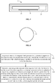
FIG. 5 illustrates a schematic cross-sectional diagram of an electronic device according to an exemplary embodiment. -
FIG. 6 illustrates a schematic structural diagram of a magnetism isolation sheet according to an exemplary embodiment. -
FIG. 7 illustrates a flow chart of a determining method for a charging region according to an exemplary embodiment. -
FIG. 8 illustrates a block diagram of a determining device for a charging region according to an exemplary embodiment. -
FIG. 9 illustrates a block diagram of another determining device for a charging region according to an exemplary embodiment. -
FIG. 10 illustrates a block diagram of a further determining device for a charging region according to an exemplary embodiment. -
FIG. 11 illustrates a block diagram of a yet further determining device for a charging region according to an exemplary embodiment. -
FIG. 12 illustrates a block diagram of a determining device for a charging region according to an exemplary embodiment. - Reference will now be made in detail to exemplary embodiments, examples of which are illustrated in the accompanying drawings. The following description refers to the accompanying drawings in which the same numbers in different drawings represent the same or similar elements unless otherwise represented. The implementations set forth in the following description of exemplary embodiments do not represent all implementations consistent with the present invention. Instead, they are merely examples of devices and methods consistent with aspects related to the present invention as recited in the appended claims.
- The terms used in the present invention are adopted for the purpose of describing specific embodiments only, and are not intended to limit this application. The singular forms "a/an", "said" and "the" used in the present invention and the appended claims may further include plural forms unless the contexts clearly indicate other meanings. It should further be understood that the term "and/or" used herein refers to and includes any or all possible combinations of one or more of the associated listed items.
- It should be understood that although the terms "first", "second" and "third" may be employed in the present invention to describe various information, the information should not be limited to these terms. These terms are only used to distinguish the same type of information from one another. For example, "first information" may also be referred to as "second information" without departing from the scope of this application. Similarly, "second information" may also be referred to as "first information". Depending on the context, the word "if" as used herein may be interpreted as "when" or "while" or "in response to determining that".
-
FIG. 1 illustrates a schematic structural diagram of awireless charging system 100 according to an exemplary embodiment. As illustrated inFIG. 1 , thewireless charging system 100 may include a wireless charging base 1 and anelectronic device 2 cooperating with the wireless charging base 1, so as to charge a battery in theelectronic device 2 wirelessly via the interaction between the wireless charging base 1 and theelectronic device 2. The wireless charging base 1 may include acylindrical magnet 11. Thecylindrical magnet 11 may be disposed axially along a thickness of the wireless charging base 1. Theelectronic device 2 may include acharging coil component 22 and acompass sensor 23. Thecompass sensor 23 may be configured to detect magnetic field intensities of a magnetic field generated by thecylindrical magnet 11 in a first direction (that is, a direction denoted by an arrow A inFIG. 1 ) and a second direction (that is, a direction denoted by an arrow B inFIG. 1 ). The first direction is an axial direction of thecylindrical magnet 11. The second direction is perpendicular to the first direction. The second direction may coincide with any radial direction of thecylindrical magnet 11, which will not be specified in the present invention. - The
electronic device 2 may further include aprocessor 24. Theprocessor 24 may communicate with thecompass sensor 23 to acquire data detected by thecompass sensor 23. Specifically, theprocessor 24 may be configured to determine, according to the magnetic field intensities of the magnetic field in the first direction A and the second direction B detected by thecompass sensor 23, a charging region formed by thecylindrical magnet 11 and adapted to thecharging coil component 22. Specifically, a point, at which the magnetic field intensity is zero in the first direction A, may be taken as a first point, and a point, at which the magnetic field intensity is zero in the second direction B, may be taken as a second point. The charging region is a circular region with the second point as a center of a circle, with a distance between the first point and the second point as a radius, and passing through the first point. When a user holds and moves theelectronic device 2 to align the internalcharging coil component 22 with the circular region, theelectronic device 2 can be charged. Specifically, an indication lamp may be provided on theelectronic device 2 to indicate the user that theelectronic device 2 is already aligned with the wireless charging base 1. Alternatively, a charging indication mark may be displayed on a display interface of theelectronic device 2 to prompt the user, which will not be specified in the present invention. - The circular region formed by the
cylindrical magnet 11 will be described in detail below. As illustrated inFIG. 3 , with respect to the relative position between thecylindrical magnet 11 and the wireless charging base 1, it is assumed that a north magnetic pole of thecylindrical magnet 11 is closer to a surface, for placing theelectronic device 2, of the wireless charging base 1, and a south magnetic pole of the cylindrical magnet is closer to a bottom surface of the wireless charging base 1. When placed on the surface of the wireless charging base 1, theelectronic device 2 will be in a magnetic field above thecylindrical magnet 11, that is, in a magnetic field closer to the north magnetic pole. - Further, still as illustrated in
FIG. 3 , an axis of thecylindrical magnet 11 is taken as a boundary, magnetic induction lines formed in a radial direction located at two sides of the axis are taken as an example. For instance, inFIG. 3 , magnetic induction lines L1, L2 and L3 are formed at the right of thecylindrical magnet 11, and magnetic induction lines L4, L5 and L6 are formed at the left of thecylindrical magnet 11. With the magnetic induction line L1 and a coordinate system xoy as an example, at the end of the magnetic induction line L1 closer to the north magnetic pole, an intensity Bz1 of the magnetic field in a first direction A that can be detected by thecompass sensor 23 is positive. As gradually moving away from the north magnetic pole, the magnetic field intensity in the first direction A that can be detected by thecompass sensor 23 gradually decreases. Until the magnetic field intensity in the first direction A is detected to be zero at a point E1. As further moving away from the north magnetic pole, the intensity Bz1 of the magnetic field in the first direction A that can be detected by thecompass sensor 23 is negative. In this way, thecompass sensor 23 can determine the edge of the charging region according to the change in the direction of the detected magnetic field intensity. Similarly, by detecting the magnetic induction line L2, it can be determined that the intensity Bz2 of the magnetic field is zero at E2, is positive at the left of E2, and is negative at the right of E2. By detecting the magnetic induction line L3, it can be determined that the intensity Bz3 of the magnetic field is zero at E3, is positive at the left of the E3, and is negative at the right of the E3. Of course, when the direction of the coordinate system xoy is changed, the positive and negative property of the detected magnetic field intensity may be changed correspondingly, which will not be specified in the present invention. - Further, it is assumed that the
electronic device 2 moves in a direction denoted by an arrow C, after being placed on the wireless charging base 1. At the right of thecylindrical magnet 11, the magnetic field intensity, detected by thecompass sensor 23, on the magnetic induction lines L1, L2 and L3 are all positive. At the left of the cylindrical magnet, the magnetic field intensity, detected by thecompass sensor 23, on the magnetic induction lines L1, L2 and L3 are all negative. Therefore, thecompass sensor 23 or theprocessor 24 can determine a center of a circle for a charging region according to the change in the direction of the detected magnetic field intensity. - It can be understood that when the spaced distance between the
compass sensor 23 and thecylindrical magnet 11 is different, the spaced distance between the first point and the second point will also be different. Specifically, the spaced distance between thecompass sensor 23 and thecylindrical magnet 11 is inversely related with the spaced distance between the first point and the second point. That is to say, the larger the spaced distance between thecompass sensor 23 and thecylindrical magnet 11, the smaller the corresponding charging region will be. It can be seen that, according to the technical solution of the present invention, a corresponding charging region can be determined for a differentelectronic device 2, improving the efficiency of a charging process. - In view of the above embodiment, a wireless charging base 1 as illustrated in
FIG. 4 is further provided in the present invention. The wireless charging base 1 may include acylindrical magnet 11 and ashell 12. Thecylindrical magnet 11 is disposed in theshell 12 and forms a magnetic field outside theshell 12. Thecylindrical magnet 11 is disposed axially along a thickness of the wireless charging base 1. As illustrated inFIG. 4 , theshell 12 may be a cylinder. In other embodiments, theshell 12 may also be a cube, a cuboid or an ellipsoid, which will not be specified in the present invention. - In view of the above embodiment, an
electronic device 2 is further provided in the present invention. Theelectronic device 2 can cooperate with the wireless charging base 1 as illustrated inFIG. 4 to charge theelectronic device 2 wirelessly. As illustrated inFIG. 2 ,FIG. 5 and FIG. 6 , theelectronic device 2 may include a chargingcoil component 22, acompass sensor 23 and aprocessor 24. Thecompass sensor 23 is configured to detect magnetic field intensities of a magnetic field generated by thecylindrical magnet 11 in a first direction and a second direction. The first direction is an axial direction of thecylindrical magnet 11, and the second direction is perpendicular to the first direction. Theprocessor 24 is configured to determine, according to the magnetic field intensities in the first direction and the second direction detected by thecompass sensor 23, a charging region adapted to the chargingcoil component 22. A point, at which the magnetic field intensity is zero in the first direction, is taken as a first point, and a point, at which the magnetic field intensity is zero in the second direction, is taken as a second point. The charging region is a circular region with the second point as a center of a circle, with a distance between the first point and the second point as a radius, and passing through the first point. - In view of this embodiment, due to the influence from a manufacturing process, three axes in the
compass sensor 23 may not be orthogonal to one another, so non-orthogonal errors of thecompass sensor 23 need to be corrected. After non-orthogonal coordinate system correction, the three axes in the compass sensor may be considered to be orthogonal to one another. However, when thecompass sensor 23 is installed in the electronic device, due to installation errors, it is not necessarily ensured that a coordinate system of thecompass sensor 23 is parallel to a coordinate system of the electronic device. Therefore, it is further needed to correct the installation errors of the data acquired by thecompass sensor 23, to obtain the magnetic field intensity described in the above embodiment. - In an embodiment, the
electronic device 2 may further include aback plate 21 and amagnetism isolation sheet 25. Themagnetism isolation sheet 25 is located on one side of the chargingcoil component 22 away from theback plate 21, and themagnetism isolation sheet 25 is a circular sheet. The magnetism isolation sheet 3 may perform symmetric compression on the magnetic field generated by thecylindrical magnet 11, thereby reducing the influence of themagnetism isolation sheet 25 on the magnetic field, and being favorable for improving the accuracy of the magnetic field intensity detected by thecompass sensor 23. - In another embodiment, the
processor 24 may further correct the magnetic field having been through non-error correction and installation error correction, to obtain a first corrected magnetic field intensity in a first direction and a second corrected magnetic field intensity in a second direction. A point, at which the first corrected magnetic field intensity is zero, is taken as a first point, and a point, at which the second corrected magnetic field intensity is zero, is taken as a second point. - Specifically, the
processor 24 may be configured to perform hard magnetic correction or soft magnetic correction on the detected magnetic field. Of course, in other embodiments, hard magnetic correction and soft magnetic correction may be performed on the magnetic field, which will not be specified in the present invention. A particular correction solutions for hard magnetic correction and soft magnetic correction are as follows: - In an embodiment, when the magnetic field generated by the wireless charging base 1 is subjected to a constant magnetic field, hard magnetic correction may be performed. For example, when the
electronic device 2 moves on the wireless charging base 1 in an 8-shaped movement track, theprocessor 24 may correct the magnetic field according to an extreme value of the detected magnetic field intensities in the first direction A and the second direction B. Specifically, when theelectronic device 2 moves in an 8-shaped movement track, a maximum value and a minimum value of the magnetic field intensities in the first direction and the second direction are acquired and then, the magnetic field is corrected according to an average value of the maximum value and the minimum value. - In another embodiment, when the magnetic field generated by the wireless charging base 1 is subjected to a magnetic material or other magnetism isolation materials, soft magnetic correction may be performed. For example, the
processor 24 may also perform ellipsoid fitting correction according to multiple groups of detected magnetic field intensities, each group including a detected magnetic field intensity in the first direction, a detected magnetic field intensity in the second direction and a detected magnetic field intensity in a third direction. The third direction is perpendicular to the first direction and the second direction. - Specifically, the soft magnetic correction is to correct an ellipsoidal magnetic field formed by compression due to the influence of external factors, into a regular spherical magnetic field. It can be understood that a regular ellipsoid comply with the following formula in a coordinate system of xyz-o:

where a is a radius on an x axis, b is a radius on a y axis, c is a radius on a z axis, and R, x0, y0 and z0 are constants. - The regular sphere may meet:

where R is a radius. - Further, it may be assumed that the measured values detected by the
compass sensor 23 are [x1, y1, z1], where x1 is a magnetic field intensity on the x axis, y1 is a magnetic field intensity on the y axis, and z1 is a translation parameter on the z axis. It is assumed that the corrected values are [x2, y2, z2], where x2 is the corrected magnetic field intensity on the x axis, y2 is the corrected magnetic field intensity on the y axis, and z2 is the corrected magnetic field intensity on the z axis. Further, it may be assumed that translation parameters between the ellipsoidal magnetic field and the spherical magnetic field are [ox, oy, oz], where ox is a translation parameter on the x axis, oy is a translation parameter on the y axis, and oz is a translation parameter on the z axis. It is assumed that scaling parameters are [gx, gy, gz], where gx is a scaling parameter on the x axis, gy is a scaling parameter on the y axis, and gz is a scaling parameter on the z axis, thereby obtaining:


- The relationship between the measured values and the corrected values is substituted into the regular sphere formula to further solve ox, oy, oz, gx, gy and gz by means of derivation, a Gaussian elimination method, a least square method, etc. The solved ox, oy, oz, gx, gy and gz are substituted into the relationship between the measured values and the corrected values again to obtain the corrected values, thus completing the ellipsoid fitting correction.
- With the corrected magnetic field obtained based on any one of the above modes, the first corrected magnetic field intensity in the first direction and the second corrected magnetic field intensity in the second direction may be obtained according to the relationship between the magnetic field before the correction and the magnetic field after the correction, and the detected magnetic field intensities. A point, at which the first corrected magnetic field intensity is zero, is taken as a first point, and a point, at which the second corrected magnetic field intensity is zero, is taken as a second point. A charging region is a circular region with the second point as a center of a circle, with a distance between the first point and the second point as a radius, and passing through the first point.
- Based on the technical solution of the present invention, a determining method for a charging region is further provided. The determining method is applied to an electronic device. The electronic device can cooperate with a wireless charging base to charge the electronic device wirelessly. The wireless charging base includes a cylindrical magnet disposed axially along a thickness of the wireless charging base, and the electronic device includes a charging coil component.
-
FIG. 7 illustrates a flow chart of a determining method for a charging region according to an exemplary embodiment. As illustrated inFIG. 7 , the method is applied to a terminal and may include the following steps: - In
step 601, magnetic field intensities of a magnetic field generated by the cylindrical magnet in a first direction and a second direction are acquired. The first direction is an axial direction of the cylindrical magnet, and the second direction is perpendicular to the first direction. - In this embodiment, the magnetic field intensities in the first direction and the second direction may be acquired through the
compass sensor 23. The first direction is an axial direction of thecylindrical magnet 11, and the second direction is perpendicular to the first direction. The second direction may be any radial direction of thecylindrical magnet 11, which will not be specified in the present invention. - In
step 602, a charging region formed by the cylindrical magnet and adapted to the charging coil component is determined according to the magnetic field intensities in the first direction and the second direction. A point, at which the magnetic field intensity is zero in the first direction, is taken as a first point, and a point, at which the magnetic field intensity is zero in the second direction, is taken as a second point. The charging region is a circular region with the second point as a center of a circle, with a distance between the first point and the second point as a radius, and passing through the first point. - In this embodiment, by detecting the magnetic field intensities in the first direction and the second direction, the first point at which the magnetic field intensity is zero in the first direction and the second point at which the magnetic field intensity is zero in the second direction can be determined. A radius of the charging region is determined according to the distance between the first point and the second point. A circular region passing through the first point is formed by taking the second point as a center of a circle. As such, the circular region is the charging region adapted to the charging coil component.
- It can be understood that when the spaced distance between the
compass sensor 23 and thecylindrical magnet 11 is different, the spaced distance between the first point and the second point will also be different. Specifically, the spaced distance between thecompass sensor 23 and thecylindrical magnet 11 is inversely related with the spaced distance between the first point and the second point. That is to say, the larger the spaced distance between thecompass sensor 23 and thecylindrical magnet 11, the smaller the corresponding charging region will be. - In the above embodiments, the determining method may further include the following step of correcting the detected magnetic field to obtain a first corrected magnetic field intensity in the first direction and a second corrected magnetic field intensity in the second direction. A point, at which the first corrected magnetic field intensity is zero, is taken as the first point, and a point, at which the second corrected magnetic field intensity is zero, is taken as the second point. Based on this, by correcting the magnetic field, the influence of an external magnetic field on the magnetic field generated by the cylindrical magnet may be reduced, and the accuracy of the alignment between the
electronic device 2 and the wireless charging base 1 may be improved. - Specifically, the
processor 24 of the electronic device may be further configured to perform hard magnetic correction or soft magnetic correction on the detected magnetic field. Of course, in other embodiments, hard magnetic correction and soft magnetic correction may be performed on the magnetic field, which will not be specified in the present invention. - Specifically, in an embodiment, when the
electronic device 2 moves on the wireless charging base 1 in an 8-shaped movement track, theprocessor 24 may correct the magnetic field according to an extreme value of the detected magnetic field intensities in the first direction A and the second direction B. Specifically, when theelectronic device 2 moves in an 8-shaped movement track, a maximum value and a minimum value of the magnetic field intensities in the first direction and the second direction are acquired. Then, the magnetic field is corrected according to an average value of the maximum value and the minimum value. - In another embodiment, the
processor 24 may further perform ellipsoid fitting correction according to multiple groups of detected magnetic field intensities, each group including a detected magnetic field intensity in the first direction, a detected magnetic field intensity in the second direction and a detected magnetic field intensity in a third direction. The third direction is perpendicular to the first direction and the second direction. - Specifically, the soft magnetic correction is to correct an ellipsoidal magnetic field formed by compression due to the influence of external factors, into a regular spherical magnetic field. It can be understood that a regular ellipsoid complies with the following formula:


- Further, it can be assumed that the measured values detected by the
compass sensor 23 are [x1, y1, z1], and the corrected values are [x2, y2, z2]. It can be further assumed that translation parameters between the ellipsoidal magnetic field and the spherical magnetic field are [ox, oy, oz], and scaling parameters are [gx, gy, gz], thereby obtaining:


- The relationship between the measured values and the corrected values is substituted into the regular sphere formula to further solve ox, oy, oz, gx, gy and gz by means of derivation, a Gaussian elimination method, a least square method, etc. The solved ox, oy, oz, gx, gy and gz are substituted into the relationship between the measured values and the corrected values again to obtain the corrected values, thus completing the ellipsoid fitting correction.
- Corresponding to the aforementioned embodiments of the determining method for a charging region, embodiments of a determining device for a charging region is further provided in the present inventions.
-
FIG. 8 illustrates a block diagram of a determining device for a charging region according to an exemplary embodiment. The determining device is applied to an electronic device. The electronic device may cooperate with a wireless charging base to charge the electronic device wirelessly. The wireless charging base includes a cylindrical magnet disposed axially along a thickness of the wireless charging base. The electronic device includes a charging coil component. - As illustrated in
FIG. 8 , the determining device includes anacquisition module 701 and adetermination module 702. - The
acquisition module 701 is configured to acquire magnetic field intensities of a magnetic field generated by the cylindrical magnet in a first direction and a second direction. The first direction is an axial direction of the cylindrical magnet, and the second direction is perpendicular to the first direction. - The
determination module 702 is configured to determine, according to the magnetic field intensities in the first direction and the second direction, a charging region formed by the cylindrical magnet and adapted to the charging coil component. A point, at which the magnetic field intensity is zero in the first direction, is taken as a first point, and a point, at which of the magnetic field intensity is zero in the second direction, is taken as a second point. The charging region is a circular region with the second point as a center of a circle, with a distance between the first point and the second point as a radius, and passing through the first point. -
FIG. 9 illustrates a block diagram of another determining device for a charging region according to an exemplary embodiment. In this embodiment, on the basis of the above embodiment as illustrated inFIG. 8 , the determining device may further include acorrection module 703. - The
correction module 703 is configured to correct the detected magnetic field to obtain a first corrected magnetic field intensity in the first direction and a second corrected magnetic field intensity in the second direction. A point, at which the first corrected magnetic field intensity is zero, is taken as the first point, and a point, at which the second corrected magnetic field intensity is zero, is taken as the second point. -
FIG. 10 illustrates a block diagram of another determining device for a charging region according to an exemplary embodiment. In this embodiment, on the basis of the above embodiment as illustrated inFIG. 9 , thecorrection module 703 may include afirst acquisition unit 7031 and afirst correction unit 7032. - The
first acquisition unit 7031 is configured to acquire an extreme value of the magnetic field intensities in the first direction and the second direction, when the electronic device moves on the wireless charging base in an 8-shaped movement track. - The
first correction unit 7032 is configured to correct the magnetic field according to the extreme value of the magnetic field intensities in the first direction and the second direction. -
FIG. 11 illustrates a block diagram of another determining device for a charging region according to an exemplary embodiment. In this embodiment, on the basis of the above embodiment as illustrated inFIG. 9 , thecorrection module 703 may include asecond acquisition unit 7033 and asecond correction unit 7034. - The
second acquisition unit 7033 is configured to acquire multiple groups of magnetic field intensities, each group including a magnetic field intensity in the first direction, a magnetic field intensity in the second direction and a magnetic field intensity in a third direction. The third direction is perpendicular to the first direction and the second direction. - The
second correction unit 7034 is configured to correct the magnetic field according to the multiple groups of magnetic field intensities and an ellipsoid fitting correction algorithm. - In the device of the above embodiments, the particular mode of each module executing an operation has been described in detail in the embodiments related to the method and will not be described in detail herein.
- Since the device embodiments substantially correspond to the method embodiments, the description in the method embodiments can be referred to for related parts. The device embodiments described above are only exemplary. The units described as separate components may be or may not be physically separated, and the components displayed as units may be or may not be physical units, may be located in one place, or may be distributed on multiple network units. Some or all of the modules may be selected according to actual needs to achieve the objectives of the solution of the present invention, and can be understood and practiced by those skilled in the art without any creative effort.
- Correspondingly, a determining device for a charging region, applied to an electronic device is further provided in the present invention. The electronic device can cooperate with a wireless charging base to charge the electronic device wirelessly. The wireless charging base includes a cylindrical magnet disposed axially along a thickness of the wireless charging base. The electronic device includes: a charging coil component, a processor, and a memory configured to store processor-executable instructions. The processor is configured to acquire magnetic field intensities of a magnetic field generated by the cylindrical magnet in a first direction and a second direction. The first direction is an axial direction of the cylindrical magnet, and the second direction is perpendicular to the first direction. The processor is further configured to determine, according to the magnetic field intensities in the first direction and the second direction, a charging region formed by the cylindrical magnet and adapted to the charging coil component. A point, at which the magnetic field intensity is zero in the first direction, is taken as a first point, and a point, at which the magnetic field intensity is zero in the second direction, is taken as a second point. The charging region is a circular region with the second point as a center of a circle, with a distance between the first point and the second point as a radius, and passing through the first point.
- Correspondingly, further provided in the present invention is a terminal that can cooperate with a wireless charging base to charge the electronic device wirelessly. The wireless charging base includes a cylindrical magnet disposed axially along a thickness of the wireless charging base. The electronic device includes a charging coil component. The terminal includes a memory, and one or more programs stored in the memory. Instructions, included in one or more programs, for performing the following operations are executed by one or more processors. Magnetic field intensities of a magnetic field generated by the cylindrical magnet in a first direction and a second direction are acquired. The first direction is an axial direction of the cylindrical magnet, and the second direction is perpendicular to the first direction. A charging region formed by the cylindrical magnet and adapted to the charging coil component is determined according to the magnetic field intensities in the first direction and the second direction. A point, at which the magnetic field intensity is zero in the first direction, is taken as a first point, and a point at which the magnetic field intensity is zero in the second direction, is taken as a second point. The charging region is a circular region with the second point as a center of a circle, with a distance between the first point and the second point as a radius, and passing through the first point.
-
FIG. 12 illustrates a block diagram of a determiningdevice 900 of a charging region according to an exemplary embodiment. For example, thedevice 900 may be a mobile phone, a computer, a digital broadcast terminal, a messaging device, a gaming console, a tablet device, a medical device, exercise equipment, a personal digital assistant, and the like. - As illustrated in
FIG. 12 , thedevice 900 may include one or more of the following components: aprocessing component 902, amemory 904, apower component 906, amultimedia component 908, anaudio component 910, an Input/Output(I/O)interface 912, asensor component 914 and acommunication component 916. - The
processing component 902 typically controls the overall operation of thedevice 900, such as operations associated with display, telephone calls, data communications, camera operations, and recording operations. Theprocessing component 902 may include one ormore processors 920 to execute instructions to perform all or some of the steps in the above described methods. Moreover, theprocessing component 902 may include one or more modules which facilitate the interaction between theprocessing component 902 and other components. For instance, theprocessing component 902 may include a multimedia module to facilitate the interaction between themultimedia component 908 and theprocessing component 902. - The
memory 904 is configured to store various types of data to support the operation of thedevice 900. Examples of such data include instructions for any applications or methods operated on thedevice 900, contact data, phone book data, messages, pictures, videos, etc. Thememory 904 may be implemented using any type of volatile or non-volatile memory devices, or a combination thereof, such as a Static Random Access Memory (SRAM), an Electrically Erasable Programmable Read-Only Memory (EEPROM), an Erasable Programmable Read-Only Memory (EPROM), a Programmable Read-Only Memory (PROM), a Read-Only Memory (ROM), a magnetic memory, a flash memory, a magnetic disk or an optical disk. - The
power component 906 provides power to various components of thedevice 900. Thepower component 906 may include a power management system, one or more power sources, and any other components associated with the generation, management, and distribution of power in thedevice 900. - The
multimedia component 908 includes a screen providing an output interface between thedevice 900 and a user. In some embodiments, the screen may include a Liquid Crystal Display (LCD) and a Touch Panel (TP). If the screen includes the touch panel, the screen may be implemented as a touch screen to receive input signals from the user. The touch panel includes one or more touch sensors to sense touches, swipes, and gestures on the touch panel. The touch sensors may not only sense a boundary of a touch or swipe action, but further sense a period of time and a pressure associated with the touch or swipe action. In some embodiments, themultimedia component 908 includes a front camera and/or a rear camera. The front camera and/or the rear camera may receive external multimedia data while thedevice 900 is in an operating mode, such as a photographing mode or a video mode. Each of the front camera and the rear camera may be a fixed optical lens system or have focus and optical zoom capability. - The
audio component 910 is configured to output and/or input audio signals. For example, theaudio component 910 includes a microphone (MIC) configured to receive an external audio signal when thedevice 900 is in an operating mode, such as a call mode, a recording mode, and a voice recognition mode. The received audio signal may be further stored in thememory 904 or transmitted via thecommunication component 916. In some embodiments, theaudio component 910 further includes a speaker to output audio signals. - The I/
O interface 912 provides an interface between theprocessing component 902 and peripheral interface modules, such as a keyboard, a click wheel, buttons, and the like. The buttons may include, but are not limited to, a home button, a volume button, a start button, and a lock button. - The
sensor component 914 includes one or more sensors configured to provide status assessments in various aspects for thedevice 900. For instance, thesensor component 914 may detect an on/off status of thedevice 900, relative positioning of the components, e.g., the display and the keypad, of thedevice 900. Thesensor component 914 may further detect a change in position of thedevice 900 or a component of thedevice 900, presence or absence of contact between the user and thedevice 900, an orientation or an acceleration/deceleration of thedevice 900, and a change in temperature of thedevice 900. Thesensor component 914 may include a proximity sensor configured to detect presence of an object nearby without any physical contact. Thesensor component 914 may also include a light sensor, such as a Complementary Metal Oxide Semiconductor (CMOS) or Charge Coupled Device (CCD) image sensor, configured for use in an imaging application. In some embodiments, thesensor component 914 may further include an acceleration sensor, a gyroscope sensor, a magnetic sensor, a pressure sensor, or a temperature sensor. - The
communication component 916 is configured to facilitate wired or wireless communication between thedevice 900 and another device. Thedevice 900 may access a communication-standard-based wireless network, such as a Wireless Fidelity (WiFi) network, a 2nd-Generation (2G) or 5th-Generation (5G) network or a combination thereof. In some embodiments, thecommunication component 916 receives a broadcast signal or broadcast associated information from an external broadcast management system through a broadcast channel. In some embodiments, thecommunication component 916 further includes a Near Field Communication (NFC) module to facilitate short-range communication. For example, the NFC module may be implemented based on a Radio Frequency Identification (RFID) technology, an Infrared Data Association (IrDA) technology, an Ultra-WideBand (UWB) technology, a Bluetooth (BT) technology and another technology - In some embodiments, the
device 900 may be implemented by one or more Application Specific Integrated Circuits (ASICs), Digital Signal Processors (DSPs), Digital Signal Processing Devices (DSPDs), Programmable Logic Devices (PLDs), Field Programmable Gate Arrays (FPGAs), controllers, micro-controllers, microprocessors or other electronic components, and is configured to execute the abovementioned method. - In exemplary embodiments, there is also provided a non-transitory computer-readable storage medium including instructions, such as the
memory 904 including an instruction, and the instruction may be executed by theprocessor 920 of thedevice 900 to implement the abovementioned method. For example, the non-transitory computer-readable storage medium may be a ROM, a Compact Disc Read-Only Memory (CD-ROM), a magnetic tape, a floppy disc, an optical data storage device and the like. - The technical solution provided by embodiments of the present invention may have the following beneficial effects:
As can be seen from the above embodiments, in the present invention, a charging region is determined by providing a cylindrical magnet in a wireless charging base and detecting an intensity of a magnetic field by a compass sensor, so that the accuracy in a process of pairing for charging between the wireless charging base and the electronic device is improved. A corresponding charging region may be determined based on a spaced distance between the compass sensor and the cylindrical magnet, to adapt to different electronic devices, thereby being favorable for improving the efficiency of the charging process. - In the disclosure, it is to be understood that the terms "first" and "second" are used for descriptive purposes only and are not to be construed as indicating or implying a relative importance or implicitly indicating the number of technical features indicated. Thus, elements referred to as "first" and "second" may include one or more of the features either explicitly or implicitly. In the description of the present disclosure, "a plurality" indicates two or more unless specifically defined otherwise.
- While this specification contains many specific implementation details, these should not be construed as limitations on the scope of any claims, but rather as descriptions of features specific to particular implementations. Certain features that are described in this specification in the context of separate implementations can also be implemented in combination in a single implementation. Conversely, various features that are described in the context of a single implementation can also be implemented in multiple implementations separately or in any suitable subcombinations.
- Moreover, although features can be described above as acting in certain combinations and even initially claimed as such, one or more features from a claimed combination can in some cases be excised from the combination, and the claimed combination can be directed to a subcombination or variations of a subcombination.
- Similarly, while operations are depicted in the drawings in a particular order, this should not be understood as requiring that such operations be performed in the particular order shown or in sequential order, or that all illustrated operations be performed, to achieve desirable results. In certain circumstances, multitasking and parallel processing can be advantageous. Moreover, the separation of various system components in the implementations described above should not be understood as requiring such separation in all implementations, and it should be understood that the described program components and systems can generally be integrated together in a single software product or packaged into multiple software products.
- Other implementations of the present invention will be apparent to those skilled in the art from consideration of the specification and practice of the present invention here. The present invention is intended to cover any variations, uses, or adaptations of the present invention following the general principles thereof and including such departures from the present invention as come within known or customary practice in the art. It is intended that the specification and embodiments be considered as exemplary only, with a true scope and spirit of the present invention being indicated by the following claims.
- It will be appreciated that the present invention is not limited to the exact construction that has been described above and illustrated in the accompanying drawings, and that various modifications and changes can be made without departing from the scope thereof. It is intended that the scope of the present invention only be limited by the appended claims.
Claims (14)
- An electronic device (2), characterized by, cooperating with a wireless charging base (1) to charge the electronic device (2) wirelessly wherein the wireless charging base (1) comprises a cylindrical magnet (11), the electronic device (2) comprising:a charging coil component (22); anda processor (24) configured to acquire magnetic field intensities of a magnetic field generated by the cylindrical magnet (11) in a first direction and a second direction and to determine, according to the magnetic field intensities in the first direction and the second direction, a charging region adapted to the charging coil component (22), wherein the first direction is an axial direction of the cylindrical magnet (11), and the second direction is perpendicular to the first direction;
wherein the point at which the magnetic field intensity is zero in the first direction is taken as a first point and the point at which the magnetic field intensity is zero in the second direction is taken as a second point, and wherein the charging region is a circular region with the second point as a center of a circle, with a distance between the first point and the second point as a radius of the circle and the circle passing through the first point. - The electronic device (2) of claim 1, further comprising:
a compass sensor (23), configured to detect the magnetic field intensities of the magnetic field generated by the cylindrical magnet (11) in the first direction and the second direction,
wherein the processor (24) is configured to acquire the magnetic field intensities from the compass sensor (23). - The electronic device (2) of claim 1, further comprising:a back plate (21); anda magnetism isolation sheet (25), wherein the magnetism isolation sheet (25) is located on one side of the charging coil component (22) away from the back plate (21) and is a circular sheet.
- The electronic device (2) of claim 1, wherein the processor (24) is further configured to correct the detected magnetic field to obtain a first corrected magnetic field intensity in the first direction and a second corrected magnetic field intensity in the second direction; and
a point, at which the first corrected magnetic field intensity is zero, is taken as the first point, and a point, at which the second corrected magnetic field intensity is zero, is taken as the second point. - The electronic device (2) of claim 4, wherein the processor (24) is configured to perform at least one of the following on the detected magnetic field: hard magnetic correction or soft magnetic correction.
- The electronic device (2) of claim 5, wherein when the electronic device (2) moves on the wireless charging base (1) in an 8-shaped movement track, the processor (24) is configured to correct the magnetic field according to an extreme value of the detected magnetic field intensities in the first direction and the second direction.
- The electronic device (2) of claim 5, wherein when the electronic device (2) moves on the wireless charging base (1) in an 8-shaped movement track, the processor (24) is configured to:
acquire a maximum value and a minimum value of the detected magnetic field intensities in the first direction and the second direction, and correct the magnetic field according to an average value of the maximum value and the minimum value. - The electronic device (2) of claim 5, wherein the processor (24) is configured to perform ellipsoid fitting correction according to multiple groups of detected magnetic field intensities, each group including a detected magnetic intensity in the first direction, a detected magnetic intensity in the second direction and a detected magnetic intensity a third direction, wherein the third direction is perpendicular to the first direction and the second direction.
- A method for determining a charging region, applied to an electronic device (2) cooperating with a wireless charging base (1) to charge the electronic device (2) wirelessly through the wireless charging base (1), wherein the wireless charging base (1) comprises a cylindrical magnet (11) disposed axially along a thickness of the wireless charging base (1) and wherein the electronic device (2) comprises a charging coil component (22), the method comprising:acquiring (601) magnetic field intensities of a magnetic field generated by the cylindrical magnet (11) in a first direction and a second direction, wherein the first direction is an axial direction of the cylindrical magnet (11), and the second direction is perpendicular to the first direction; anddetermining (602), according to the magnetic field intensities in the first direction and the second direction, a charging region adapted to the charging coil component (22), wherein a point at which the magnetic field intensity is zero in the first direction is taken as a first point and a point at which the magnetic field intensity is zero in the second direction is taken as a second point, and wherein the charging region is a circular region with the second point as a center of a circle, with a distance between the first point and the second point as a radius of the circle and the circle passing through the first point.
- The method of claim 9, further comprising:correcting a detected magnetic field to obtain a first corrected magnetic field intensity in the first direction and a second corrected magnetic field intensity in the second direction; andtaking a point, at which the first corrected magnetic field intensity is zero, as the first point, and taking a point, at which the second corrected magnetic field intensity is zero, as the second point.
- The method of claim 10, wherein correcting the detected magnetic field comprises:when the electronic device (2) moves on the wireless charging base (1) in an 8-shaped movement track, acquiring an extreme value of the magnetic field intensities in the first direction and the second direction; andcorrecting the magnetic field according to the extreme value of the magnetic field intensities in the first direction and the second direction.
- The method of claim 11, wherein acquiring the extreme value of the magnetic field intensities in the first direction and the second direction comprises:acquiring a maximum value and a minimum value of the detected magnetic field intensities in the first direction and the second direction; andcorrecting the magnetic field according to the extreme value of the magnetic field intensities in the first direction and the second direction comprises:correcting the magnetic field according to an average value of the maximum value and the minimum value.
- The method of claim 10, wherein correcting the detected magnetic field comprises:acquiring multiple groups of magnetic field intensities, each group including a magnetic field intensity in the first direction, a magnetic field intensity in the second direction and a magnetic field intensity in a third direction, wherein the third direction is perpendicular to the first direction and the second direction; andcorrecting the magnetic field according to the multiple groups of magnetic field intensities and an ellipsoid fitting correction algorithm.
- A computer-readable storage medium with computer instructions stored thereon, wherein the instructions, when executed by a processor, implement the steps of the method of any one of claims 9 to 13.
Applications Claiming Priority (1)
| Application Number | Priority Date | Filing Date | Title |
|---|---|---|---|
| CN201910959250.0A CN112653249B (en) | 2019-10-10 | 2019-10-10 | Wireless charging system, charging area determining method and device and electronic equipment |
Publications (1)
| Publication Number | Publication Date |
|---|---|
| EP3806283A1 true EP3806283A1 (en) | 2021-04-14 |
Family
ID=70165925
Family Applications (1)
| Application Number | Title | Priority Date | Filing Date |
|---|---|---|---|
| EP20167889.3A Pending EP3806283A1 (en) | 2019-10-10 | 2020-04-03 | Method for determining charging region, electronic device and computer-readable medium |
Country Status (3)
| Country | Link |
|---|---|
| US (1) | US11418058B2 (en) |
| EP (1) | EP3806283A1 (en) |
| CN (1) | CN112653249B (en) |
Families Citing this family (1)
| Publication number | Priority date | Publication date | Assignee | Title |
|---|---|---|---|---|
| CN112653249B (en) * | 2019-10-10 | 2023-06-06 | 北京小米移动软件有限公司 | Wireless charging system, charging area determining method and device and electronic equipment |
Citations (4)
| Publication number | Priority date | Publication date | Assignee | Title |
|---|---|---|---|---|
| CN103884326A (en) * | 2012-12-21 | 2014-06-25 | 北京合众思壮科技股份有限公司 | Electronic compass electronic compass |
| US20150022020A1 (en) * | 2012-01-16 | 2015-01-22 | Nokia Corporation | Method and shielding units for inductive energy coils |
| US20150022194A1 (en) * | 2013-07-18 | 2015-01-22 | Blackberry Limited | Magnetometer for aligning a portable device on a planar charging surface of an inductive charging unit |
| US20180052649A1 (en) * | 2016-08-19 | 2018-02-22 | Apple Inc. | Coordination of Device Operation on Wireless Charging Surface |
Family Cites Families (39)
| Publication number | Priority date | Publication date | Assignee | Title |
|---|---|---|---|---|
| FR2609206B1 (en) * | 1986-12-30 | 1992-02-14 | Thomson Cgr | MAGNETIC CORRECTIVE DEVICE FOR MAGNETIC FIELD INHOMOGENEITIES IN A MAGNET |
| US6760678B1 (en) * | 2000-04-11 | 2004-07-06 | Electronics Tomorrow Limited | Electronic compass |
| US6962001B2 (en) * | 2003-11-10 | 2005-11-08 | The Research Institute For Electric And Magnetic Materials | Magnetic north detecting device and magnetic north detecting method |
| US7275008B2 (en) * | 2005-09-02 | 2007-09-25 | Nokia Corporation | Calibration of 3D field sensors |
| US7687941B2 (en) * | 2008-04-02 | 2010-03-30 | Puthalath Koroth Raghuprasad | Cordless power transfer |
| US20110050164A1 (en) * | 2008-05-07 | 2011-03-03 | Afshin Partovi | System and methods for inductive charging, and improvements and uses thereof |
| WO2011156768A2 (en) * | 2010-06-11 | 2011-12-15 | Mojo Mobility, Inc. | System for wireless power transfer that supports interoperability, and multi-pole magnets for use therewith |
| US20130229078A1 (en) * | 2010-10-22 | 2013-09-05 | Spinlectrix Inc. | Control for rotating electrical machinery |
| JP5958345B2 (en) * | 2010-11-25 | 2016-07-27 | 日本電気株式会社 | Mobile terminal with electronic compass and direction calculation method |
| US11342777B2 (en) * | 2011-01-18 | 2022-05-24 | Mojo Mobility, Inc. | Powering and/or charging with more than one protocol |
| US9178369B2 (en) * | 2011-01-18 | 2015-11-03 | Mojo Mobility, Inc. | Systems and methods for providing positioning freedom, and support of different voltages, protocols, and power levels in a wireless power system |
| JP2013169122A (en) * | 2012-02-17 | 2013-08-29 | Panasonic Corp | Non-contact charge module and portable terminal having the same |
| KR101890676B1 (en) * | 2012-02-23 | 2018-08-22 | 엘지전자 주식회사 | Mobile terminal terminal wireless charging module |
| KR101977088B1 (en) * | 2013-01-08 | 2019-05-10 | 엘지전자 주식회사 | Wireless power transmitter |
| US20160003270A1 (en) * | 2013-03-15 | 2016-01-07 | L. Christopher Franklin | Mounting apparatus |
| US9893557B2 (en) * | 2013-07-12 | 2018-02-13 | Schneider Electric USA, Inc. | Method and device for foreign object detection in induction electric charger |
| EP3218674B1 (en) * | 2014-11-11 | 2021-06-23 | Intel Corporation | Extended kalman filter based autonomous magnetometer calibration |
| US10411524B2 (en) * | 2015-06-23 | 2019-09-10 | Witricity Corporation | Systems, methods and apparatuses for guidance and alignment in electric vehicles wireless inductive charging systems |
| KR20170027624A (en) * | 2015-09-02 | 2017-03-10 | 삼성전자주식회사 | Cardle for wireless charging and electronic device applied thereto |
| AU2016368167B2 (en) * | 2015-12-10 | 2021-04-22 | Nuvasive Specialized Orthopedics, Inc. | External adjustment device for distraction device |
| EP3351134B1 (en) * | 2017-01-20 | 2020-01-08 | The Gillette Company LLC | Personal care product system with flux guiding members |
| US10632318B2 (en) * | 2017-03-21 | 2020-04-28 | Boston Scientific Neuromodulation Corporation | External charger with three-axis magnetic field sensor to determine implantable medical device position |
| WO2018203251A1 (en) * | 2017-05-02 | 2018-11-08 | Ahmad Mughal Rabia | Wireless kinetic charger |
| CN107196420B (en) * | 2017-07-14 | 2021-01-26 | 京东方科技集团股份有限公司 | Wireless charging device and wireless charging method thereof |
| US10720277B2 (en) * | 2017-09-08 | 2020-07-21 | Witricity Corporation | Ferrite arrangement in a wireless power-transfer structure to mitigate dimensional tolerance effects on performance |
| US20190198212A1 (en) * | 2017-12-22 | 2019-06-27 | Marc Levy | Personal electronic device case and mounting system |
| US10797506B2 (en) * | 2018-04-05 | 2020-10-06 | Witricity Corporation | DC to AC power conversion using a wireless power receiver |
| US10668829B2 (en) * | 2018-05-04 | 2020-06-02 | Witricity Corporation | Passive flux bridge for charging electric vehicles |
| DE102018207394A1 (en) * | 2018-05-14 | 2019-11-14 | Volkswagen Aktiengesellschaft | Positioning method for inductive charging of electric vehicles |
| CN110832301B (en) * | 2018-05-30 | 2022-05-27 | 务实诊断有限公司 | Optical magneto-optical method for detecting biological and chemical substances |
| CN208285078U (en) * | 2018-06-28 | 2018-12-25 | 东莞市金唐电子科技有限公司 | A kind of magnetic-type vehicle-mounted wireless charging device |
| US20200021144A1 (en) * | 2018-07-16 | 2020-01-16 | Witricity Corporation | Method and system for reducing magnetic field emissions from double-d couplers |
| CN109038844B (en) * | 2018-07-24 | 2020-12-22 | 深圳市零壹创新科技有限公司 | A wireless charging device |
| US10888939B2 (en) * | 2018-11-06 | 2021-01-12 | Nanjing Chervon Industry Co., Ltd. | Miter saw |
| US20200247257A1 (en) * | 2019-02-01 | 2020-08-06 | Menriyan Wireless High Power Technology (HK) Limited | Intelligent power wireless charging system for electric wheelchairs, robotic arm and ranging sensor thereof |
| US10903697B2 (en) * | 2019-03-19 | 2021-01-26 | Witricity Corporation | Methods and systems for multi-phase coil control |
| CN110649719A (en) * | 2019-08-23 | 2020-01-03 | 华为技术有限公司 | A wireless charging method and electronic device |
| CN112653249B (en) * | 2019-10-10 | 2023-06-06 | 北京小米移动软件有限公司 | Wireless charging system, charging area determining method and device and electronic equipment |
| US11532702B2 (en) * | 2020-05-19 | 2022-12-20 | Taiwan Semiconductor Manufacturing Co., Ltd. | Source/drain isolation structures for leakage prevention |
-
2019
- 2019-10-10 CN CN201910959250.0A patent/CN112653249B/en active Active
-
2020
- 2020-03-04 US US16/809,208 patent/US11418058B2/en active Active
- 2020-04-03 EP EP20167889.3A patent/EP3806283A1/en active Pending
Patent Citations (4)
| Publication number | Priority date | Publication date | Assignee | Title |
|---|---|---|---|---|
| US20150022020A1 (en) * | 2012-01-16 | 2015-01-22 | Nokia Corporation | Method and shielding units for inductive energy coils |
| CN103884326A (en) * | 2012-12-21 | 2014-06-25 | 北京合众思壮科技股份有限公司 | Electronic compass electronic compass |
| US20150022194A1 (en) * | 2013-07-18 | 2015-01-22 | Blackberry Limited | Magnetometer for aligning a portable device on a planar charging surface of an inductive charging unit |
| US20180052649A1 (en) * | 2016-08-19 | 2018-02-22 | Apple Inc. | Coordination of Device Operation on Wireless Charging Surface |
Also Published As
| Publication number | Publication date |
|---|---|
| US20210111588A1 (en) | 2021-04-15 |
| CN112653249A (en) | 2021-04-13 |
| CN112653249B (en) | 2023-06-06 |
| US11418058B2 (en) | 2022-08-16 |
Similar Documents
| Publication | Publication Date | Title |
|---|---|---|
| US10750007B2 (en) | Method and device for preventing terminal from being inadvertently touched | |
| US11523369B2 (en) | Signal reception method and apparatus | |
| US12538094B2 (en) | Ranging capacity request method, ranging capacity sending method, and ranging capacity receiving method | |
| US9729775B2 (en) | Auto-focusing method and auto-focusing device | |
| EP3200125B1 (en) | Fingerprint template input method and device | |
| US20230009389A1 (en) | One-hand operation method and electronic device | |
| EP3768008A1 (en) | Method and apparatus for indicating and searching for position of synchronous broadcast block of defined cell, and base station | |
| US9131348B2 (en) | Mobile terminal and controlling method thereof | |
| EP3276301A1 (en) | Mobile terminal and method for calculating a bending angle | |
| EP3863344A1 (en) | Terminal positioning method, apparatus, electronic device and storage medium | |
| US10061497B2 (en) | Method, device and storage medium for interchanging icon positions | |
| US12425988B2 (en) | Processing capability request, processing capability sending, and processing capability receiving methods and apparatuses | |
| EP3553919B1 (en) | Method and device for controlling wireless charging | |
| EP3771232A1 (en) | Information reporting and configuration method and device, user equipment and base station | |
| CN105975038A (en) | Prompt method and device of charging port detection result | |
| EP3828716A1 (en) | Method and apparatus for identifying electronic device, terminal device, and electronic device | |
| US11418058B2 (en) | Wireless charging system, method for determining charging region, electronic device, and computer-readable storage medium | |
| EP3742186B1 (en) | Method and device for sensing terminal action | |
| CN114428184B (en) | Current testing method, current testing device, terminal and storage medium | |
| CN115033129A (en) | Holding mode identification method, holding mode identification device, holding mode identification equipment and storage medium | |
| US20230198643A1 (en) | Beam receiving method and apparatus, electronic device, and computer-readable storage medium | |
| EP4057729B1 (en) | Occupancy time determination method and apparatus and electronic device | |
| CN120528483A (en) | Grip calibration method, device, electronic device and storage medium | |
| CN106658404A (en) | Terminal equipment positioning method and apparatus | |
| CN117392232A (en) | Image calibration method, device, terminal and storage medium |
Legal Events
| Date | Code | Title | Description |
|---|---|---|---|
| PUAI | Public reference made under article 153(3) epc to a published international application that has entered the european phase |
Free format text: ORIGINAL CODE: 0009012 |
|
| STAA | Information on the status of an ep patent application or granted ep patent |
Free format text: STATUS: THE APPLICATION HAS BEEN PUBLISHED |
|
| AK | Designated contracting states |
Kind code of ref document: A1 Designated state(s): AL AT BE BG CH CY CZ DE DK EE ES FI FR GB GR HR HU IE IS IT LI LT LU LV MC MK MT NL NO PL PT RO RS SE SI SK SM TR |
|
| AX | Request for extension of the european patent |
Extension state: BA ME |
|
| STAA | Information on the status of an ep patent application or granted ep patent |
Free format text: STATUS: REQUEST FOR EXAMINATION WAS MADE |
|
| 17P | Request for examination filed |
Effective date: 20210702 |
|
| RBV | Designated contracting states (corrected) |
Designated state(s): AL AT BE BG CH CY CZ DE DK EE ES FI FR GB GR HR HU IE IS IT LI LT LU LV MC MK MT NL NO PL PT RO RS SE SI SK SM TR |
|
| STAA | Information on the status of an ep patent application or granted ep patent |
Free format text: STATUS: EXAMINATION IS IN PROGRESS |
|
| 17Q | First examination report despatched |
Effective date: 20230127 |