EP3806258A1 - Control device and power conversion device - Google Patents
Control device and power conversion device Download PDFInfo
- Publication number
- EP3806258A1 EP3806258A1 EP18920608.9A EP18920608A EP3806258A1 EP 3806258 A1 EP3806258 A1 EP 3806258A1 EP 18920608 A EP18920608 A EP 18920608A EP 3806258 A1 EP3806258 A1 EP 3806258A1
- Authority
- EP
- European Patent Office
- Prior art keywords
- power
- current
- command value
- direct current
- idp
- Prior art date
- Legal status (The legal status is an assumption and is not a legal conclusion. Google has not performed a legal analysis and makes no representation as to the accuracy of the status listed.)
- Pending
Links
Images




Classifications
-
- H—ELECTRICITY
- H02—GENERATION; CONVERSION OR DISTRIBUTION OF ELECTRIC POWER
- H02J—ELECTRIC POWER NETWORKS; CIRCUIT ARRANGEMENTS OR SYSTEMS FOR SUPPLYING OR DISTRIBUTING ELECTRIC POWER; SYSTEMS FOR STORING ELECTRIC ENERGY
- H02J1/00—Circuit arrangements for DC mains or DC distribution networks
-
- H—ELECTRICITY
- H02—GENERATION; CONVERSION OR DISTRIBUTION OF ELECTRIC POWER
- H02J—ELECTRIC POWER NETWORKS; CIRCUIT ARRANGEMENTS OR SYSTEMS FOR SUPPLYING OR DISTRIBUTING ELECTRIC POWER; SYSTEMS FOR STORING ELECTRIC ENERGY
- H02J1/00—Circuit arrangements for DC mains or DC distribution networks
- H02J1/04—Current-controlled supply systems, e.g. constant-current supply systems
-
- H—ELECTRICITY
- H02—GENERATION; CONVERSION OR DISTRIBUTION OF ELECTRIC POWER
- H02J—ELECTRIC POWER NETWORKS; CIRCUIT ARRANGEMENTS OR SYSTEMS FOR SUPPLYING OR DISTRIBUTING ELECTRIC POWER; SYSTEMS FOR STORING ELECTRIC ENERGY
- H02J1/00—Circuit arrangements for DC mains or DC distribution networks
- H02J1/06—Two-wire DC power distribution systems
-
- H—ELECTRICITY
- H02—GENERATION; CONVERSION OR DISTRIBUTION OF ELECTRIC POWER
- H02J—ELECTRIC POWER NETWORKS; CIRCUIT ARRANGEMENTS OR SYSTEMS FOR SUPPLYING OR DISTRIBUTING ELECTRIC POWER; SYSTEMS FOR STORING ELECTRIC ENERGY
- H02J1/00—Circuit arrangements for DC mains or DC distribution networks
- H02J1/14—Balancing load and power generation in DC networks
-
- H—ELECTRICITY
- H02—GENERATION; CONVERSION OR DISTRIBUTION OF ELECTRIC POWER
- H02J—ELECTRIC POWER NETWORKS; CIRCUIT ARRANGEMENTS OR SYSTEMS FOR SUPPLYING OR DISTRIBUTING ELECTRIC POWER; SYSTEMS FOR STORING ELECTRIC ENERGY
- H02J3/00—Circuit arrangements for AC mains or AC distribution networks
- H02J3/36—Arrangements for transfer of electric power between AC networks via high-voltage DC [HVDC] links; Arrangements for transfer of electric power between generators and networks via HVDC links
-
- Y—GENERAL TAGGING OF NEW TECHNOLOGICAL DEVELOPMENTS; GENERAL TAGGING OF CROSS-SECTIONAL TECHNOLOGIES SPANNING OVER SEVERAL SECTIONS OF THE IPC; TECHNICAL SUBJECTS COVERED BY FORMER USPC CROSS-REFERENCE ART COLLECTIONS [XRACs] AND DIGESTS
- Y02—TECHNOLOGIES OR APPLICATIONS FOR MITIGATION OR ADAPTATION AGAINST CLIMATE CHANGE
- Y02E—REDUCTION OF GREENHOUSE GAS [GHG] EMISSIONS, RELATED TO ENERGY GENERATION, TRANSMISSION OR DISTRIBUTION
- Y02E60/00—Enabling technologies; Technologies with a potential or indirect contribution to GHG emissions mitigation
- Y02E60/60—Arrangements for transfer of electric power between AC networks or generators via a high voltage DC link [HVCD]
Definitions
- An embodiment of the invention relates to a control device and a power conversion device.
- a power conversion device that is connected to one terminal of the two terminals receives an input of a power command value supplied from a higher-level system, generates a current command value (Idp) based on the power command value, and performs a constant power control (APR), etc.
- a power conversion device that is connected to the other terminal receives data of the current command value Idp generated by the one terminal via a communication line.
- the direct current power transmission system correctly functions because the same current command value Idp is input to the power conversion devices of the two terminals at an appropriate timing.
- the power conversion devices of the terminals include operation modes that are independent of the terminal-terminal communication.
- the direct current power transmission system has controllability constraints, system-operation constraints, etc. Therefore, it is assumed that such an operation mode should only be used as a backup.
- Patent Literature 1 JP-A 2016-152733 (Kokai)
- Embodiments of the invention provide a control device, and a power conversion device including the control device; the control device controls a power converter that is connected to a direct current power transmission system and can operate without using terminal-terminal communication.
- a control device controls a power converter that can be connected to a terminal of a direct current power transmission system transmitting power according to a current command value that is set.
- the control device includes a first characteristic setter having a first characteristic preset.
- the first characteristic outputs an output terminal voltage for the power converter.
- the output terminal voltage corresponds to a current of a current control based on a current command value set at a power receiving end of the direct current power transmission system.
- the output terminal voltage of the first characteristic monotonously decreasing with respect to the current of the current control.
- a direct current power transmission system that can be operated without using terminal-terminal communication can be constructed.
- FIG. 1 is a block diagram illustrating a power conversion device according to an embodiment.
- the direct current power transmission system 1 includes two power conversion devices 10a and 10b and a direct current power line 3.
- the power conversion device 10a is connected between the direct current power line 3 and an alternating current circuit 2a.
- the power conversion device 10b is connected between an alternating current circuit 2b and the direct current power line 3.
- the alternating current circuits 2a and 2b each can have configurations including an alternating current power supply, an alternating current power line, an alternating current load, etc., of 50 Hz or 60 Hz.
- the alternating current circuits 2a and 2b can be different power systems.
- the direct current power transmission system 1 can transmit bidirectional direct current power.
- the connection terminals of the power conversion devices 10a and 10b can be a power transmission end that transmits direct current power or can be a power receiving end that receives direct current power.
- the connection terminal of one power conversion device 10a is a power transmission end
- the connection terminal of the other power conversion device 10b is a power receiving end.
- the connection terminal of the one power conversion device 10a is a power receiving end.
- the power conversion devices 10a and 10b have the same configuration, and the configuration of the power conversion device 10a is described below.
- Components 20b to 38b of the power conversion device 10b are respectively the same as components 20a to 38b of the power conversion device 10a, and a description is omitted as appropriate.
- the power conversion device is applicable to a multi-terminal direct current power transmission system including three or more terminals.
- the power conversion device 10a includes the power converter 20a and the control device 30a.
- the power converter 20a converts an alternating current voltage into a direct current voltage and outputs the direct current voltage according to a gate signal vg generated by the control device 30a.
- the power converter 20a is a separately-excited power converter and is, for example, a thyristor valve.
- the control device 30a generates the gate signal vg based on a direct current voltage Vd and a direct current Id and supplies the generated gate signal vg to the power converter 20a.
- the control device 30a includes the current command value setter 34a, the direct current voltage controller 36a, and the direct current controller 38a.
- the control device 30a selects and operates one of the current command value setter 34a or the direct current controller 38a automatically or as appropriate.
- the current command value setter 34a is selected; when the power conversion device 10a is the power receiving end, the direct current controller 38a is selected.
- the direct current controller 38a operates to track the direct current command value Idp when the power conversion device 10a is the power receiving end and the direct current command value Idp is set.
- the direct current voltage controller 36a temporarily performs a voltage control operation that operates to finalize the operating point.
- FIG. 2 is a graph illustrating a characteristic of the power conversion device of FIG. 1 .
- the graph of FIG. 2 is an example of the characteristic output by the current command value setter 34a.
- the current command value setter 34a includes data of it's own direct current terminal voltage Vd with respect to the data of the current command value Idp.
- the range Idp_min to Idp_max of the current command value Idp is the range of the current command values that may be set by the direct current power transmission system 1.
- the range of the current command value Idp matches the setting range of the current command value of the direct current power transmission system 1.
- the direct current terminal voltage Vd is set to monotonously decrease within a prescribed range with respect to the current command value Idp.
- the monotonously-decreasing range is, for example, from 95% of the rated voltage to the rated voltage.
- the maximum value of the range of the direct current terminal voltage Vd is the rated voltage because the power transmission efficiency is high when the direct current terminal voltage of the power transmission end is the rated voltage, which is the maximum voltage when operating.
- the direct current terminal voltage Vd favorably has a linear characteristic with respect to the current command value Idp, the characteristic may not be linear as long as the characteristic monotonously decreases.
- the current command value setter 34a stores the data of the direct current terminal voltage Vd with respect to the current command value Idp in a table format.
- the current command value setter 34a may store the current command value Idp as a function relating to the direct current terminal voltage Vd.
- the direct current voltage controller (AVR) 36a is selected after releasing the characteristic set by the current command value setter 34a in a power flow reversal, which is elaborated below.
- the power conversion device 10a controls the reversed direct current voltage by the AVR 36a by setting the current command value Idp to the minimum value. Subsequently, the power conversion device 10a transitions to a current control operation.
- the direct current controller (ACR) 38a operates to track the current command value Idp generated based on the power command value supplied from the higher-level system.
- the power command value that is supplied from the higher-level system is used as the current command value Idp by the current command value generator 32.
- the current command value generator 32 may be provided in the control device 30a or provided at the higher-level system side; the control device 30a may be configured to set the current command value Idp from the higher-level system.
- the ACR 38a is selected when the characteristic set by the current command value setter 34a of the power flow reversal is released.
- the ACR 38a is selected by a power flow reversal signal; for example, the ACR 38a sets the current command value Idp to the minimum value Idp_min.
- control devices 30a and 30b each include margin angle control functions when the power converters 20a and 20b are thyristor valves.
- the margin angle control function limits the direct current terminal voltage Vd when the direct current Id flowing through the direct current power line 3 is large and the control angle is large.
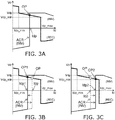
- FIGS. 3A to 3C are graphs for describing an operation of the power conversion devices of the embodiment.
- the horizontal axis is the direct current Id flowing in the direct current power line 3
- the vertical axis is the direct current terminal voltage Vd of the power conversion devices 10a and 10b.
- the power conversion devices 10a and 10b output a positive direct current terminal voltage Vd when the direct current terminal voltage Vd is positive.
- the power conversion devices 10a and 10b output a negative direct current terminal voltage -Vd when the direct current terminal voltage Vd is negative.
- the direct current terminal voltage Vd has opposite signs between the power transmission end and power receiving end of the direct current power transmission system 1.
- the Vd-Id characteristic is called the output characteristic for the power conversion devices or the power transmission end and the power receiving end.
- the power conversion device 10a is at the power transmission end
- the power conversion device 10b is at the power receiving end.
- the power conversion device 10b of the power receiving end outputs a negative direct current terminal voltage -Vd when the power conversion device 10a of the power transmission end outputs a positive direct current terminal voltage Vd.
- the output characteristic of the power transmission end is a thick solid line illustrated by (REC), and the output characteristic of the power receiving end is a thin solid line illustrated by (INV).
- an operating point OP of the direct current power transmission system 1 is the point where the output characteristic of the power transmission end and the output characteristic of the power receiving end intersect.
- the power conversion device 10b operates in a current control mode (an ACR mode) set with the current command value Idp.
- ACR(INV) The operation of the ACR mode is illustrated by ACR(INV) in the figure.
- the current command value Idp is within the setting range Idp_min to Idp_max of the current command value.
- the current command value setter 34a is selected because the current command value Idp is within the range set by the current command value setter 34a, and the direct current terminal voltage Vd is uniquely determined for the direct current Id that is current-controlled to the current command value Idp.
- Idp When the current command value Idp that is provided to the power receiving end is set to Idp1 that is less than Idp, the current command value Idp1 ⁇ Id temporarily occurs. Therefore, Id is controlled toward Idp1 by the direct current control of the power receiving end, and Id decreases.
- Idp1 > Id occurs due to the decrease of Id ; the phase of the control angle of the power transmission end is advanced by the ACR 38a; and Vd increases.
- the decrease of Id and the increase of Vd continue until reaching the next operating point OP1 that is determined by the ACR characteristic of the power transmission end and the Idp-Vd characteristic of the power transmission end.
- Id and Vd When the decrease of Id and the increase of Vd reach the next operating point OP1, Id and Vd again have stable operations. For example, such behavior is similar even when Vd temporarily decreases or Id temporarily increases due to a disturbance, etc.
- the direct current Id is controlled toward a current command value Idp2 by the direct current controller 38b of the power conversion device 10b of the power receiving end, and the direct current Id increases.
- Idp2 ⁇ Id occurs due to the increase of the direct current Id; a control angle ⁇ of the power transmission end is lagged by a direct current control, and the direct current terminal voltage Vd decreases.
- the increase of Id and the decrease of Vd continue until reaching the next operating point OP2 that is determined by the characteristic of the ACR 38b of the power conversion device 10b of the power receiving end and the characteristic of the current command value setter 34a of the power conversion device 10a of the power transmission end.
- the increase of Id and the decrease of Vd again are stable when the next operating point OP2 is reached. Such behavior is similar even when Vd temporarily increases or Id temporarily decreases due to a disturbance, etc.
- the operating point is automatically determined without the power conversion device 10a of the power transmission end receiving the set current command value Idp via a communication line, etc.
- FIG. 4 and FIGS. 5A to 5D An operation when the power transmission end and the power receiving end are interchanged by a power flow reversal will now be described with reference to FIG. 4 and FIGS. 5A to 5D.
- the power transmission end and the power receiving end will be interchanged; therefore, the terminal to which the power conversion device 10a is connected is called the A-terminal, and the terminal to which the power conversion device 10b is connected is called the B-terminal.
- the output characteristic of the A-terminal is illustrated by a thick solid line
- the output characteristic of the B-terminal is illustrated by a thin solid line.
- FIG. 4 is an example of a flowchart for describing an operation of the power conversion devices of the embodiment.
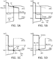
- FIGS. 5A to 5D are graphs for describing an operation of the power conversion devices of the embodiment.
- step S1 as shown in FIG. 4 the power conversion device 10b of the B-terminal receives the supply of the current command value Idp from the higher-level system and performs an ACR operation to track the current command value Idp.
- the power conversion device 10a of the A-terminal operates at the operating point OP determined by the Idp-Vd characteristic of the current command value setter 34a.
- step S1 is as shown in FIG. 5A .
- the state of FIG. 5A is the same as the operation already elaborated in FIG. 3A .
- step S2 the power conversion device 10a of the A-terminal receives a power flow reversal command from the higher-level system and releases the Idp-Vd characteristic.
- the power conversion device 10a transitions to the ACR operation and sets the current command value Idp of the ACR operation to the minimum value Idp_min. At this time, the power conversion device 10b continues the ACR operation.
- the direct current terminal voltage Vd of the power conversion device 10a reverses (step S3), and the operating point transitions to OP3 determined by the ACR characteristic of the B-terminal and the AVR characteristic of the A-terminal illustrated by AVR(A).
- step S4 the power conversion device 10b receives a current command value after the power flow reversal.
- the power conversion device 10a operates with the AVR characteristic illustrated by AVR(A) of FIG. 5C
- the power conversion device 10b operates with the ACR characteristic illustrated by ACR(B).
- An operating point OP4 is determined by the AVR characteristic illustrated by AVR(A) and the ACR characteristic illustrated by ACR(B).
- the Idp-Vd characteristic is set by the current command value setter 34b.
- the Idp-Vd characteristic of the power conversion device 10b may be the same as or different from the Idp-Vd characteristic of the power conversion device 10a.
- the power conversion device 10a of the A-terminal operates with the ACR characteristic illustrated by ACR(A), and the power conversion device 10b of the B-terminal operates with the Idp-Vd characteristic.
- An operating point OP5 is determined by these characteristics (step S6).
- the power conversion devices 10a and 10b of the embodiment can perform the power flow reversal operation.
- FIGS. 6A and 6B are block diagrams illustrating a portion of the control device of the power conversion device of the embodiment.
- the power conversion devices 10a and 10b of the embodiment can automatically startup and perform the power flow reversal operation without installing a high-quality highly reliable communication line.
- Such a logic circuit can be provided for each of the control devices 30a and 30b.
- the control device 30a includes flip-flops 40, 42, and 43, comparators 44 and 46, switchers 45 and 47, an outputter 48, and an Idp setter 49.
- the control device 30a includes the current command value generator 32.
- the current command value generator 32 supplies the data of the current command value Idp to one input of the switcher 45.
- the flip-flops 40, 42, and 43 are RS flip-flops.
- the flip-flop 40 includes, for example, two flip-flops 41a and 41b; one of the two flip-flops 41a and 41b is selected according to whether the power conversion device 10a is the power transmission end or the power receiving end. In the example, the flip-flop 41b is selected when the power conversion device 10a is the power transmission end, and the flip-flop 41a is selected when the power conversion device 10b is the power receiving end.
- the output of the flip-flop 40 is connected to reset inputs R of the flip-flops 42 and 43.
- a startup command CMD1 is input to a set input S of the flip-flop 42.
- the startup command CMD1 is input when the power conversion device 10a is the power receiving end.
- a power flow reversal command CMD2 is input to a set input S of the flip-flop 43.
- the outputs of the flip-flops 42 and 40 each are connected to inputs of the comparator 44.
- the comparator 44 selects and outputs the flip-flop 42 or 40 that outputs "1".
- the output of the comparator 44 supplies a switch signal to the switcher 45.
- the output of the comparator 44 and the output of the flip-flop 43 are connected to inputs of the other comparator 46.
- the comparator 46 selects and outputs the output of the comparator 44 or the output of the flip-flop 43 that outputs "1".
- the output of the comparator 46 supplies a switch signal to the switcher 47.
- the switcher 45 switches between two inputs and supplies a signal that is input to the outputter 48.
- the data of the current command value Idp from the current command value generator 32 is supplied to one input of the switcher 45.
- a fixed value of the current command value is set to the other input of the switcher 45.
- the switcher 45 supplies the data of either input to the outputter 48 according to the switch signal supplied from the comparator 44.
- the switcher 45 supplies, to the outputter 48, the data of the current command value Idp output from the current command value generator 32.
- the switcher 45 supplies 0.1pu, which is the fixed value, to the outputter 48.
- the switcher 47 sets the limit value of the signal of the outputter 48 by switching between two inputs.
- the outputter 48 limits the output to the limit value corresponding to the output of the switcher 47.
- the switcher 47 supplies 0.1pu, which is the fixed value, as a limit value to the outputter 48.
- the switcher 45 supplies the data of Idp output from the Idp setter 49 as a limit value to the outputter 48.
- the Idp setter 49 sets Idp for Vd.
- Idp has the maximum value Idp_max when the minimum value Vd_min of the direct current terminal voltage Vd is 95% of a rated value Vdp, and the value at this time is 1.1pu.
- Idp has the minimum value Idp_min when the direct current terminal voltage Vd is the rated value Vdp.
- the startup sequence starts by inputting the startup command CMD1 to the power receiving end.
- Vd starts to increase (or decrease) from 0.0pu; therefore, the current command value Idp of the power transmission end is set to Idp_max according to the Idp-Vd characteristic of the Idp setter 49.
- Idp_max is set to a value that is greater than the upper limit of Idp that can be input to the power receiving end by the Idp setter 49. For example, Idp_max is set to 1.1pu when a maximum of 1.0pu is provided to the power receiving end as Idp.
- the power flow reversal sequence is started by inputting the power flow reversal command CMD2 to the power conversion device 10a of the power transmission end.
- the power flow reversal command CMD2 may be input by a manual operation at the power transmission end or may be transmitted from the power conversion device 10b of the power receiving end that includes the current command value generator 32b.
- the power flow reversal command CMD2 is transmitted from the power conversion device 10b of the power receiving end, it is unnecessary to synchronize the power flow reversal command CMD2 between the power transmission end and the power receiving end. Therefore, it is not always necessary to use a high-quality communication for the transmission of the commands and/or the data between the two terminals.
- the transition of the power flow reversal operation from the INV end to the REC end may be transmitted based on a condition of the direct current Id.
- the power flow reversal command CMD2 may be detected at the power transmission end by Id falling below 0.15pu, etc. In such a case, terminal-terminal communication is not used at all.
- Vd After the polarity reversal of Vd, Vd further decreases (or increases), and the flip-flop 40 that sets the Vd condition of the A-terminal is set when Vd reaches -0.9pu (or 0.9pu). Then, the power flow reversal command CMD2 is reset, and Idp is set by the current command value generator 32a in the power conversion device 10a of the A-terminal.
- the flip-flop 40 that sets the Vd condition of the B-terminal when Vd reaches -0.9pu (or 0.9pu) is reset, and Idp of the power conversion device 10b of the B-terminal is set according to the Idp-Vd characteristic.
- Vd reaches the value determined by the Idp-Vd characteristic of the power conversion device 10b of the B-terminal
- the normal operating state is reached in which Id and Vd are controlled by the ACR characteristic of the power conversion device 10a of the A-terminal and the Idp-Vd characteristic of the power conversion device 10b of the B-terminal.
- one of the devices can autonomously startup due to the startup command CMD1 and can automatically perform the power flow reversal operation due to the power flow reversal command CMD2 without using a high-quality highly reliable communication line.
- the components of the power conversion device including the control device described above may be realized by an arithmetic device including a CPU (Central Processing Unit), an MPU (Micro Processing Unit), etc. Some or all of the components described above may be realized by being sequentially executed by a program stored in a memory device connected to the arithmetic device.
- arithmetic device including a CPU (Central Processing Unit), an MPU (Micro Processing Unit), etc.
- FIG. 7A is a block diagram illustrating the power conversion device of the comparative example.
- FIG. 7B is a graph for describing an operation of the power conversion device of FIG. 7A .
- the direct current power transmission system 101 includes power converters 120a and 120b and control devices 130a and 130b.
- the power converter 120a is connected between the alternating current circuit 2a and the direct current power line 3.
- the power converter 120b is connected between the direct current power line 3 and the alternating current circuit 2b.
- the control device 130a includes a constant voltage controller (AVR) 136a and a constant current controller (ACR) 138a.
- the control device 130a includes a margin angle controller 139a.
- the AVRs 136a and 136b, the ACRs 138a and 138b, and the margin angle controllers 139a and 139b are the same components between the control devices 130a and 130b; the control device 130a will now be described.
- the direct current terminal voltage Vd and the direct current Id are input, and the gate signal vg is generated so that the direct current terminal voltage Vd and the direct current Id track the voltage command value and the current command value.
- control device 130a of the power transmission end performs the ACR operation of causing the direct current Id to track the current command value Idp according to the current command value Idp that is supplied. This is illustrated by ACR(REC) in the figure.
- the control device 130b of the power receiving end receives the data of the current command value Idp via a communication line 150.
- the ACR part 138b of the control device 130b sets the ACR characteristic to a current ( Idp - ⁇ Idp ) that is a current margin ⁇ Idp amount subtracted from the current command value Idp.
- An operating point OPc is determined by the AVR characteristic (AVR(INV)) of the power transmission end and the ACR characteristic (ACR(REC)) of the power receiving end.
- the current command value Idp that is generated by a current command value generator 132 is transmitted to the power receiving end by using the communication line 150 for the terminal-terminal communication, and the same Idp is shared by the two ends. Also, other than the current command value Idp, the power flow reversal or startup/stop timing are synchronized by transferring a flow direction signal or a startup/stop command between the two terminals.
- the power transmission and/or the power flow reversal are not appropriately performed when the data of the current command value Idp is transmitted with a large delay between the two terminals or when the data from one is missing.
- the terminal-terminal communication is used in the signal transfer of the current command value Idp, the flow direction command, the startup/stop command, etc., between the two ends; therefore, there is a possibility that a delay of the terminal-terminal communication may affect the stability of the control and/or the abnormal operation of the power flow reversal sequence or the startup/stop sequence. Therefore, high quality and high reliability of the terminal-terminal communication are necessary.
- High-quality highly reliable communication refers to being high-speed and having little effect of the communication amount on the communication speed.
- control device 130a of the comparative example there are cases where a technique of continuing the power transmission is used regardless of the terminal-terminal communication when the terminal-terminal communication is disconnected.
- FIG. 8 is a block diagram for describing the operation when communication is disconnected in the power conversion device of the comparative example.
- the operating point can be uniquely determined by setting the current of the ACR characteristic to Idp_min when the reception of the current command value Idp stops.
- the direct current that can be transmitted is undesirably limited to Idp_min, and the desired power cannot be transmitted.
- the direct current Id that is detected at the power receiving end is set to the current command value when the reception of the current command value Idp stops.
- the command value of the direct current Id to be controlled by the ACR of the power receiving end is ( Id - ⁇ Idp ), and similarly to the case described above, the direct current is controlled to ( Idp_min - ⁇ Idp ) .
- a third technique there are cases where an operator that operates the control device 130a is located at the power transmission end side and an operator that operates the control device 130b is located at the power receiving end side, and the current command value Idp is manually set by the operators using another communicator such as a telephone, etc.
- another communicator such as a telephone
- the first and second techniques described above it is difficult to perform the power flow reversal because Idp of the power receiving end cannot be set to the desired value. Accordingly, the first and second techniques also must be utilized on the premise of being a backup when an abnormality of the terminal-terminal communication occurs.
- the power conversion devices 10a and 10b of the embodiment include the control devices 30a and 30b that include the current command value setters 34a and 34b.
- the current command value setters 34a and 34b set the values of their own direct current terminal voltages Vd with respect to the current command value Idp.
- the Idp-Vd characteristic is set so that Vd monotonously decreases with respect to Idp. Therefore, in the Idp-Vd characteristics of the current command value setters 34a and 34b, Vd is uniquely determined by setting Idp.
- the operating point is stably set because Vd of the power conversion device 10a of the power transmission end is determined according to Idp set by the ACR characteristic of the power conversion device 10b of the power receiving end. Because the operating point is set by the desired current command value Idp, the desired power transmission can be performed even when the terminal-terminal communication is disconnected.
- the power flow reversal can be easily performed by releasing the Idp-Vd characteristic of the power conversion device 10a of the power transmission end.
- a stable operating point can be set in the power flow reversal state by setting the Idp-Vd characteristic in the power conversion device 10b of the power receiving end.
- the desired power transmission can be continued and the power flow reversal can be performed without a high-quality highly reliable terminal-terminal communication.
Landscapes
- Engineering & Computer Science (AREA)
- Power Engineering (AREA)
- Inverter Devices (AREA)
- Direct Current Feeding And Distribution (AREA)
Abstract
Description
- An embodiment of the invention relates to a control device and a power conversion device.
- In a direct current power transmission system that includes two terminals, for example, a power conversion device that is connected to one terminal of the two terminals receives an input of a power command value supplied from a higher-level system, generates a current command value (Idp) based on the power command value, and performs a constant power control (APR), etc. A power conversion device that is connected to the other terminal receives data of the current command value Idp generated by the one terminal via a communication line. Thus, the direct current power transmission system correctly functions because the same current command value Idp is input to the power conversion devices of the two terminals at an appropriate timing.
- Transmission data that is missing, delayed, etc., may cause a fault in the operation of the direct current power transmission system. Therefore, it is necessary for the terminal-terminal communication to be high-quality and highly reliable. To communicate with high quality and high reliability, it is necessary to lay a dedicated communication line, install dedicated communication devices, etc.; and there is a tendency for the cost burden to become large.
- Even when high-quality highly reliable terminal-terminal communication is realized, it is difficult to completely eliminate communication faults; therefore, the power conversion devices of the terminals include operation modes that are independent of the terminal-terminal communication. However, in an operation mode that is independent of the terminal-terminal communication, the direct current power transmission system has controllability constraints, system-operation constraints, etc. Therefore, it is assumed that such an operation mode should only be used as a backup.
- Patent Literature 1:
JP-A 2016-152733 - Embodiments of the invention provide a control device, and a power conversion device including the control device; the control device controls a power converter that is connected to a direct current power transmission system and can operate without using terminal-terminal communication.
- According to an embodiment of the invention, a control device is provided and controls a power converter that can be connected to a terminal of a direct current power transmission system transmitting power according to a current command value that is set. The control device includes a first characteristic setter having a first characteristic preset. When the power converter is set at a power transmission end of the direct current power transmission system, the first characteristic outputs an output terminal voltage for the power converter. The output terminal voltage corresponds to a current of a current control based on a current command value set at a power receiving end of the direct current power transmission system. The output terminal voltage of the first characteristic monotonously decreasing with respect to the current of the current control.
- According to embodiments of the invention, a direct current power transmission system that can be operated without using terminal-terminal communication can be constructed.
-
- [
FIG. 1 ]
FIG. 1 is a block diagram illustrating a power conversion device according to an embodiment. - [
FIG. 2 ]
FIG. 2 is a graph illustrating a characteristic of the power conversion device ofFIG. 1 . - [
FIG. 3 ]
FIGS. 3A to 3C are graphs for describing an operation of the power conversion devices of the embodiment. - [
FIG. 4 ]
FIG. 4 is an example of a flowchart for describing an operation of the power conversion devices of the embodiment. - [
FIG. 5 ]
FIGS. 5A to 5D are graphs for describing an operation of the power conversion devices of the embodiment. - [
FIG. 6 ]
FIGS. 6A and 6B are block diagrams illustrating a portion of the control device of the power conversion device of the embodiment. - [
FIG. 7 ]
FIG. 7A is a block diagram illustrating the power conversion device of the comparative example.
FIG. 7B is a graph for describing an operation of the power conversion device ofFIG. 7A . - [
FIG. 8 ]
FIG. 8 is a block diagram for describing the operation when communication is disconnected in the power conversion device of the comparative example. - Various embodiments are described below with reference to the accompanying drawings.
- The drawings are schematic and conceptual; and the relationship between the thickness and width of the portions, the proportions of sizes among portions, etc., are not necessarily the same as the actual values. Also, the dimensions and proportions may be illustrated differently among drawings, even when the same portion is illustrated.
- In the specification and drawings, components similar to those described previously or illustrated in an antecedent drawing are marked with the same reference numerals, and a detailed description is omitted as appropriate.
-
FIG. 1 is a block diagram illustrating a power conversion device according to an embodiment. - The configuration of a direct current power transmission system also is shown in
FIG. 1 . As shown inFIG. 1 , the direct currentpower transmission system 1 includes twopower conversion devices current power line 3. Thepower conversion device 10a is connected between the directcurrent power line 3 and an alternatingcurrent circuit 2a. Thepower conversion device 10b is connected between an alternatingcurrent circuit 2b and the directcurrent power line 3. For example, the alternatingcurrent circuits current circuits - The direct current
power transmission system 1 can transmit bidirectional direct current power. The connection terminals of thepower conversion devices power conversion device 10a is a power transmission end, the connection terminal of the otherpower conversion device 10b is a power receiving end. When the connection terminal of the otherpower conversion device 10b is a power transmission end, the connection terminal of the onepower conversion device 10a is a power receiving end. Thepower conversion devices power conversion device 10a is described below.Components 20b to 38b of thepower conversion device 10b are respectively the same ascomponents 20a to 38b of thepower conversion device 10a, and a description is omitted as appropriate. - Although the direct current
power transmission system 1 that includes two terminals is described hereinbelow, the power conversion device is applicable to a multi-terminal direct current power transmission system including three or more terminals. - The
power conversion device 10a includes thepower converter 20a and thecontrol device 30a. Thepower converter 20a converts an alternating current voltage into a direct current voltage and outputs the direct current voltage according to a gate signal vg generated by thecontrol device 30a. Thepower converter 20a is a separately-excited power converter and is, for example, a thyristor valve. - The
control device 30a generates the gate signal vg based on a direct current voltage Vd and a direct current Id and supplies the generated gate signal vg to thepower converter 20a. - The
control device 30a includes the currentcommand value setter 34a, the directcurrent voltage controller 36a, and the directcurrent controller 38a. Thecontrol device 30a selects and operates one of the currentcommand value setter 34a or the directcurrent controller 38a automatically or as appropriate. When thepower conversion device 10a is the power transmission end, the currentcommand value setter 34a is selected; when thepower conversion device 10a is the power receiving end, the directcurrent controller 38a is selected. - The direct
current controller 38a operates to track the direct current command value Idp when thepower conversion device 10a is the power receiving end and the direct current command value Idp is set. - When the
power conversion device 10a becomes the power receiving end due to power flow reversal, the directcurrent voltage controller 36a temporarily performs a voltage control operation that operates to finalize the operating point. -
FIG. 2 is a graph illustrating a characteristic of the power conversion device ofFIG. 1 . - The graph of
FIG. 2 is an example of the characteristic output by the currentcommand value setter 34a. - As shown in
FIG. 2 , the currentcommand value setter 34a includes data of it's own direct current terminal voltage Vd with respect to the data of the current command value Idp. The range Idp_min to Idp_max of the current command value Idp is the range of the current command values that may be set by the direct currentpower transmission system 1. Favorably, the range of the current command value Idp matches the setting range of the current command value of the direct currentpower transmission system 1. - The direct current terminal voltage Vd is set to monotonously decrease within a prescribed range with respect to the current command value Idp. The monotonously-decreasing range is, for example, from 95% of the rated voltage to the rated voltage. Favorably, the maximum value of the range of the direct current terminal voltage Vd is the rated voltage because the power transmission efficiency is high when the direct current terminal voltage of the power transmission end is the rated voltage, which is the maximum voltage when operating.
- Although the direct current terminal voltage Vd favorably has a linear characteristic with respect to the current command value Idp, the characteristic may not be linear as long as the characteristic monotonously decreases.
- For example, the current
command value setter 34a stores the data of the direct current terminal voltage Vd with respect to the current command value Idp in a table format. The currentcommand value setter 34a may store the current command value Idp as a function relating to the direct current terminal voltage Vd. - The direct current voltage controller (AVR) 36a is selected after releasing the characteristic set by the current
command value setter 34a in a power flow reversal, which is elaborated below. In the case of a power flow reversal of thepower conversion device 10a from the power transmission end to the power receiving end, thepower conversion device 10a controls the reversed direct current voltage by theAVR 36a by setting the current command value Idp to the minimum value. Subsequently, thepower conversion device 10a transitions to a current control operation. - When the
power conversion device 10a is the power receiving end, the direct current controller (ACR) 38a operates to track the current command value Idp generated based on the power command value supplied from the higher-level system. The power command value that is supplied from the higher-level system is used as the current command value Idp by the currentcommand value generator 32. - The current
command value generator 32 may be provided in thecontrol device 30a or provided at the higher-level system side; thecontrol device 30a may be configured to set the current command value Idp from the higher-level system. - The
ACR 38a is selected when the characteristic set by the currentcommand value setter 34a of the power flow reversal is released. TheACR 38a is selected by a power flow reversal signal; for example, theACR 38a sets the current command value Idp to the minimum value Idp_min. - Although not illustrated, the
control devices power converters current power line 3 is large and the control angle is large. - Operations of the power conversion device of the embodiment will now be described.
- First, the determination operation of the operating point between the power transmission end and the power receiving end will be described.
-
FIGS. 3A to 3C are graphs for describing an operation of the power conversion devices of the embodiment. - In the figures of
FIGS. 3A to 3C , the horizontal axis is the direct current Id flowing in the directcurrent power line 3, and the vertical axis is the direct current terminal voltage Vd of thepower conversion devices power conversion devices power conversion devices power transmission system 1. Hereinbelow, the Vd-Id characteristic is called the output characteristic for the power conversion devices or the power transmission end and the power receiving end. - In
FIGS. 3A to 3C , thepower conversion device 10a is at the power transmission end, and thepower conversion device 10b is at the power receiving end. As shown inFIGS. 3A to 3C , thepower conversion device 10b of the power receiving end outputs a negative direct current terminal voltage -Vd when thepower conversion device 10a of the power transmission end outputs a positive direct current terminal voltage Vd. The output characteristic of the power transmission end is a thick solid line illustrated by (REC), and the output characteristic of the power receiving end is a thin solid line illustrated by (INV). - As shown in
FIG. 3A , an operating point OP of the direct currentpower transmission system 1 is the point where the output characteristic of the power transmission end and the output characteristic of the power receiving end intersect. At the power receiving end, thepower conversion device 10b operates in a current control mode (an ACR mode) set with the current command value Idp. The operation of the ACR mode is illustrated by ACR(INV) in the figure. At this time, the current command value Idp is within the setting range Idp_min to Idp_max of the current command value. - In the
power conversion device 10a at the power transmission end, the currentcommand value setter 34a is selected because the current command value Idp is within the range set by the currentcommand value setter 34a, and the direct current terminal voltage Vd is uniquely determined for the direct current Id that is current-controlled to the current command value Idp. - When the current command value Idp is set to Idp1 that is less than Idp of
FIG. 3A , the operating point OP moves to an operating point OP1 as inFIG. 3B . This condition is described in detail as follows. - When the current command value Idp that is provided to the power receiving end is set to Idp1 that is less than Idp, the current command value Idp1 < Id temporarily occurs. Therefore, Id is controlled toward Idp1 by the direct current control of the power receiving end, and Id decreases. At the power transmission end, Idp1 > Id occurs due to the decrease of Id; the phase of the control angle of the power transmission end is advanced by the
ACR 38a; and Vd increases. The decrease of Id and the increase of Vd continue until reaching the next operating point OP1 that is determined by the ACR characteristic of the power transmission end and the Idp-Vd characteristic of the power transmission end. When the decrease of Id and the increase of Vd reach the next operating point OP1, Id and Vd again have stable operations. For example, such behavior is similar even when Vd temporarily decreases or Id temporarily increases due to a disturbance, etc. - When the current command value Idp is set to Idp2 that is greater than the case of
FIG. 3A , the operating point OP moves to an operating point OP2 as inFIG. 3C . This condition is described in detail as follows. - The direct current Id is controlled toward a current command value Idp2 by the direct
current controller 38b of thepower conversion device 10b of the power receiving end, and the direct current Id increases. In thepower conversion device 10a of the power transmission end, Idp2 < Id occurs due to the increase of the direct current Id; a control angle α of the power transmission end is lagged by a direct current control, and the direct current terminal voltage Vd decreases. The increase of Id and the decrease of Vd continue until reaching the next operating point OP2 that is determined by the characteristic of theACR 38b of thepower conversion device 10b of the power receiving end and the characteristic of the currentcommand value setter 34a of thepower conversion device 10a of the power transmission end. The increase of Id and the decrease of Vd again are stable when the next operating point OP2 is reached. Such behavior is similar even when Vd temporarily increases or Id temporarily decreases due to a disturbance, etc. - Thus, in the embodiment, if the current command value Idp is set in the
power conversion device 10b of the power receiving end, the operating point is automatically determined without thepower conversion device 10a of the power transmission end receiving the set current command value Idp via a communication line, etc. - An operation when the power transmission end and the power receiving end are interchanged by a power flow reversal will now be described with reference to
FIG. 4 andFIGS. 5A to 5D. In the description hereinbelow, the power transmission end and the power receiving end will be interchanged; therefore, the terminal to which thepower conversion device 10a is connected is called the A-terminal, and the terminal to which thepower conversion device 10b is connected is called the B-terminal. In the figures of the output characteristics, the output characteristic of the A-terminal is illustrated by a thick solid line, and the output characteristic of the B-terminal is illustrated by a thin solid line. -
FIG. 4 is an example of a flowchart for describing an operation of the power conversion devices of the embodiment. -
FIGS. 5A to 5D are graphs for describing an operation of the power conversion devices of the embodiment. - In step S1 as shown in
FIG. 4 , thepower conversion device 10b of the B-terminal receives the supply of the current command value Idp from the higher-level system and performs an ACR operation to track the current command value Idp. Thepower conversion device 10a of the A-terminal operates at the operating point OP determined by the Idp-Vd characteristic of the currentcommand value setter 34a. - The state of step S1 is as shown in
FIG. 5A . The state ofFIG. 5A is the same as the operation already elaborated inFIG. 3A . - In step S2, the
power conversion device 10a of the A-terminal receives a power flow reversal command from the higher-level system and releases the Idp-Vd characteristic. - Specifically, as shown in
FIG. 5B , according to the power flow reversal command, thepower conversion device 10a transitions to the ACR operation and sets the current command value Idp of the ACR operation to the minimum value Idp_min. At this time, thepower conversion device 10b continues the ACR operation. The direct current terminal voltage Vd of thepower conversion device 10a reverses (step S3), and the operating point transitions to OP3 determined by the ACR characteristic of the B-terminal and the AVR characteristic of the A-terminal illustrated by AVR(A). - In step S4, the
power conversion device 10b receives a current command value after the power flow reversal. - The
power conversion device 10a operates with the AVR characteristic illustrated by AVR(A) ofFIG. 5C , and thepower conversion device 10b operates with the ACR characteristic illustrated by ACR(B). An operating point OP4 is determined by the AVR characteristic illustrated by AVR(A) and the ACR characteristic illustrated by ACR(B). - In the
power conversion device 10b in step S5, the Idp-Vd characteristic is set by the currentcommand value setter 34b. The Idp-Vd characteristic of thepower conversion device 10b may be the same as or different from the Idp-Vd characteristic of thepower conversion device 10a. - As shown in
FIG. 5D , in thepower conversion device 10a, thepower conversion device 10a of the A-terminal operates with the ACR characteristic illustrated by ACR(A), and thepower conversion device 10b of the B-terminal operates with the Idp-Vd characteristic. An operating point OP5 is determined by these characteristics (step S6). - Thus, the
power conversion devices -
FIGS. 6A and 6B are block diagrams illustrating a portion of the control device of the power conversion device of the embodiment. - By appropriately setting a logic circuit, the
power conversion devices control devices - As shown in
FIGS. 6A and 6B , thecontrol device 30a includes flip-flops comparators switchers outputter 48, and anIdp setter 49. Thecontrol device 30a includes the currentcommand value generator 32. The currentcommand value generator 32 supplies the data of the current command value Idp to one input of theswitcher 45. - In the example, the flip-
flops flop 40 includes, for example, two flip-flops flops power conversion device 10a is the power transmission end or the power receiving end. In the example, the flip-flop 41b is selected when thepower conversion device 10a is the power transmission end, and the flip-flop 41a is selected when thepower conversion device 10b is the power receiving end. The output of the flip-flop 40 is connected to reset inputs R of the flip-flops - A startup command CMD1 is input to a set input S of the flip-
flop 42. The startup command CMD1 is input when thepower conversion device 10a is the power receiving end. A power flow reversal command CMD2 is input to a set input S of the flip-flop 43. - The outputs of the flip-
flops comparator 44. Thecomparator 44 selects and outputs the flip-flop comparator 44 supplies a switch signal to theswitcher 45. - The output of the
comparator 44 and the output of the flip-flop 43 are connected to inputs of theother comparator 46. Thecomparator 46 selects and outputs the output of thecomparator 44 or the output of the flip-flop 43 that outputs "1". The output of thecomparator 46 supplies a switch signal to theswitcher 47. - The
switcher 45 switches between two inputs and supplies a signal that is input to theoutputter 48. The data of the current command value Idp from the currentcommand value generator 32 is supplied to one input of theswitcher 45. A fixed value of the current command value is set to the other input of theswitcher 45. In the example, the minimum value Idp_min = 0.1pu of the current command value is set as the fixed value of the current command value. - The
switcher 45 supplies the data of either input to theoutputter 48 according to the switch signal supplied from thecomparator 44. When the switch signal is "1", theswitcher 45 supplies, to theoutputter 48, the data of the current command value Idp output from the currentcommand value generator 32. When the switch signal is "0", theswitcher 45 supplies 0.1pu, which is the fixed value, to theoutputter 48. - The
switcher 47 sets the limit value of the signal of theoutputter 48 by switching between two inputs. Theoutputter 48 limits the output to the limit value corresponding to the output of theswitcher 47. - When the switch signal is "1", the
switcher 47 supplies 0.1pu, which is the fixed value, as a limit value to theoutputter 48. When the switch signal is "0", theswitcher 45 supplies the data of Idp output from theIdp setter 49 as a limit value to theoutputter 48. - The
Idp setter 49 sets Idp for Vd. In the example, Idp has the maximum value Idp_max when the minimum value Vd_min of the direct current terminal voltage Vd is 95% of a rated value Vdp, and the value at this time is 1.1pu. Idp has the minimum value Idp_min when the direct current terminal voltage Vd is the rated value Vdp. - An operation of the logic circuit will now be described.
- First, the startup procedure will be described.
- The startup sequence starts by inputting the startup command CMD1 to the power receiving end. At this time, Vd starts to increase (or decrease) from 0.0pu; therefore, the current command value Idp of the power transmission end is set to Idp_max according to the Idp-Vd characteristic of the
Idp setter 49. Idp_max is set to a value that is greater than the upper limit of Idp that can be input to the power receiving end by theIdp setter 49. For example, Idp_max is set to 1.1pu when a maximum of 1.0pu is provided to the power receiving end as Idp. - As a result, at the startup, the relationship of the magnitude of Idp of the power transmission end > the magnitude of Idp of the power receiving end is maintained. Therefore, the direct current voltage polarities of the
power conversion devices flop 40 that sets the Vd condition of the INV end is set; therefore, the startup command CMD1 is reset. When Vd reaches the value determined by the Idp-Vd characteristic of thepower conversion device 10a of the power transmission end, the normal operating state is reached in which Id and Vd are controlled by the ACR characteristic of the power receiving end and the Idp-Vd characteristic of the power transmission end. - The procedure of the power flow reversal will now be described.
- The power flow reversal sequence is started by inputting the power flow reversal command CMD2 to the
power conversion device 10a of the power transmission end. The power flow reversal command CMD2 may be input by a manual operation at the power transmission end or may be transmitted from thepower conversion device 10b of the power receiving end that includes the current command value generator 32b. When the power flow reversal command CMD2 is transmitted from thepower conversion device 10b of the power receiving end, it is unnecessary to synchronize the power flow reversal command CMD2 between the power transmission end and the power receiving end. Therefore, it is not always necessary to use a high-quality communication for the transmission of the commands and/or the data between the two terminals. - The transition of the power flow reversal operation from the INV end to the REC end may be transmitted based on a condition of the direct current Id. For example, the power flow reversal command CMD2 may be detected at the power transmission end by Id falling below 0.15pu, etc. In such a case, terminal-terminal communication is not used at all.
- By any of these methods, when the power flow reversal command CMD2 is received or detected at the power transmission end (the A-terminal), the Idp-Vd characteristic of the A-terminal is released, and Idp of the A-terminal is set to Idp_min (= 0.1pu) that is set beforehand. As described in
FIG. 4 andFIGS. 5A to 5D , the power flow reversal operation is started, and the polarity of Vd reverses. - After the polarity reversal of Vd, Vd further decreases (or increases), and the flip-
flop 40 that sets the Vd condition of the A-terminal is set when Vd reaches -0.9pu (or 0.9pu). Then, the power flow reversal command CMD2 is reset, and Idp is set by the current command value generator 32a in thepower conversion device 10a of the A-terminal. - At this time, in the
power conversion device 10b of the B-terminal as well, the polarity of Vd reverses; therefore, the flip-flop 40 that sets the Vd condition of the B-terminal when Vd reaches -0.9pu (or 0.9pu) is reset, and Idp of thepower conversion device 10b of the B-terminal is set according to the Idp-Vd characteristic. - When Vd reaches the value determined by the Idp-Vd characteristic of the
power conversion device 10b of the B-terminal, the normal operating state is reached in which Id and Vd are controlled by the ACR characteristic of thepower conversion device 10a of the A-terminal and the Idp-Vd characteristic of thepower conversion device 10b of the B-terminal. - Thus, in the
power conversion devices - The components of the power conversion device including the control device described above may be realized by an arithmetic device including a CPU (Central Processing Unit), an MPU (Micro Processing Unit), etc. Some or all of the components described above may be realized by being sequentially executed by a program stored in a memory device connected to the arithmetic device.
- Effects of the
power conversion devices -
FIG. 7A is a block diagram illustrating the power conversion device of the comparative example.FIG. 7B is a graph for describing an operation of the power conversion device ofFIG. 7A . - As shown in
FIG. 7A , the direct currentpower transmission system 101 includespower converters control devices - The
power converter 120a is connected between the alternatingcurrent circuit 2a and the directcurrent power line 3. Thepower converter 120b is connected between the directcurrent power line 3 and the alternatingcurrent circuit 2b. - The
control device 130a includes a constant voltage controller (AVR) 136a and a constant current controller (ACR) 138a. Thecontrol device 130a includes amargin angle controller 139a. TheAVRs ACRs margin angle controllers control devices control device 130a will now be described. - In the
control device 130a, similarly to thecontrol device 30a of thepower conversion device 10a of the embodiment, the direct current terminal voltage Vd and the direct current Id are input, and the gate signal vg is generated so that the direct current terminal voltage Vd and the direct current Id track the voltage command value and the current command value. - As shown in
FIG. 7B , thecontrol device 130a of the power transmission end performs the ACR operation of causing the direct current Id to track the current command value Idp according to the current command value Idp that is supplied. This is illustrated by ACR(REC) in the figure. - The
control device 130b of the power receiving end receives the data of the current command value Idp via acommunication line 150. TheACR part 138b of thecontrol device 130b sets the ACR characteristic to a current (Idp - ΔIdp) that is a current margin ΔIdp amount subtracted from the current command value Idp. - An operating point OPc is determined by the AVR characteristic (AVR(INV)) of the power transmission end and the ACR characteristic (ACR(REC)) of the power receiving end.
- Thus, the current command value Idp that is generated by a current
command value generator 132 is transmitted to the power receiving end by using thecommunication line 150 for the terminal-terminal communication, and the same Idp is shared by the two ends. Also, other than the current command value Idp, the power flow reversal or startup/stop timing are synchronized by transferring a flow direction signal or a startup/stop command between the two terminals. - In the direct current
power transmission system 101 of the comparative example, the power transmission and/or the power flow reversal are not appropriately performed when the data of the current command value Idp is transmitted with a large delay between the two terminals or when the data from one is missing. - In the comparative example, the terminal-terminal communication is used in the signal transfer of the current command value Idp, the flow direction command, the startup/stop command, etc., between the two ends; therefore, there is a possibility that a delay of the terminal-terminal communication may affect the stability of the control and/or the abnormal operation of the power flow reversal sequence or the startup/stop sequence. Therefore, high quality and high reliability of the terminal-terminal communication are necessary. High-quality highly reliable communication refers to being high-speed and having little effect of the communication amount on the communication speed. When a dedicated line is laid between the two ends to realize high-quality highly reliable communication, there are many cases where the installation cost increases, the operating cost of the dedicated line increases, and the maintenance cost of the dedicated line increases.
- In the
control device 130a of the comparative example, there are cases where a technique of continuing the power transmission is used regardless of the terminal-terminal communication when the terminal-terminal communication is disconnected. -
FIG. 8 is a block diagram for describing the operation when communication is disconnected in the power conversion device of the comparative example. - When communication is disconnected as shown in
FIG. 8 , there are cases where a setting to the minimum value Idp_min of the current command value Idp is forcibly performed in the power receiving end. In a first technique in thecontrol device 130b of the power receiving end, the operating point can be uniquely determined by setting the current of the ACR characteristic to Idp_min when the reception of the current command value Idp stops. However, in this technique, the direct current that can be transmitted is undesirably limited to Idp_min, and the desired power cannot be transmitted. - In a second technique, there are cases where the direct current Id that is detected at the power receiving end is set to the current command value when the reception of the current command value Idp stops. However, for the ACR selection mode of the power receiving end, the command value of the direct current Id to be controlled by the ACR of the power receiving end is (Id - ΔIdp), and similarly to the case described above, the direct current is controlled to (Idp_min - ΔIdp).
- In a third technique, there are cases where an operator that operates the
control device 130a is located at the power transmission end side and an operator that operates thecontrol device 130b is located at the power receiving end side, and the current command value Idp is manually set by the operators using another communicator such as a telephone, etc. However, in this technique, it is necessary to constantly provide an operator at each terminal in preparation for an abnormality of the terminal-terminal communication, and a realistic operation is difficult. - In the first and second techniques described above, it is difficult to perform the power flow reversal because Idp of the power receiving end cannot be set to the desired value. Accordingly, the first and second techniques also must be utilized on the premise of being a backup when an abnormality of the terminal-terminal communication occurs.
- The
power conversion devices control devices command value setters command value setters command value setters power conversion device 10a of the power transmission end is determined according to Idp set by the ACR characteristic of thepower conversion device 10b of the power receiving end. Because the operating point is set by the desired current command value Idp, the desired power transmission can be performed even when the terminal-terminal communication is disconnected. - In the
power conversion devices power conversion device 10a of the power transmission end. Continuing, a stable operating point can be set in the power flow reversal state by setting the Idp-Vd characteristic in thepower conversion device 10b of the power receiving end. - Thus, in the
power conversion devices - Hereinabove, embodiments of the invention are described with reference to specific examples. However, the invention is not limited to these specific examples. For example, one skilled in the art may similarly practice the invention by appropriately selecting specific configurations of components such as the power converter, the control device, etc., from known art; and such practice is within the scope of the invention to the extent that similar effects can be obtained.
- Also, combinations of any two or more components of the specific examples within the extent of technical feasibility also are within the scope of the invention to the extent that the spirit of the invention is included.
- Furthermore, all power conversion devices practicable by an appropriate design modification by one skilled in the art based on the power conversion devices described above as embodiments of the invention also are within the scope of the invention to the extent that the spirit of the invention is included.
- Also, various modifications and alterations within the spirit of the invention will be readily apparent to those skilled in the art, and all such modifications and alterations also should be seen as being within the scope of the invention.
- Although several embodiments of the invention are described, these embodiments are presented as examples and are not intended to limit the scope of the invention. These novel embodiments may be implemented in other various forms, and various omissions, substitutions, and modifications can be performed without departing from the spirit of the invention. Such embodiments and their modifications are within the scope and spirit of the invention and are within the scope of the invention described in the claims and their equivalents.
Claims (7)
- A control device controlling a power converter, the power converter being capable of being connected to a terminal of a direct current power transmission system transmitting power according to a current command value that is set, the control device comprising:a first characteristic setter having a first characteristic preset,when the power converter is set at a power transmission end of the direct current power transmission system,the first characteristic outputs an output terminal voltage for the power converter, the output terminal voltage corresponding to a current of a current control based on a current command value set at a power receiving end of the direct current power transmission system,the output terminal voltage of the first characteristic monotonously decreasing with respect to the current of the current control.
- The control device according to claim 1, wherein
the first characteristic is linear. - The control device according to claim 1, wherein
the first characteristic causes the output terminal voltage to be a maximum value when the current command value that may be set at the power receiving end is a minimum value. - The control device according to claim 1, further comprising:
a current controller performing at least a current control to track the current command value that may be set. - The control device according to claim 4, wherein
the current controller operates at a maximum value of the current command value that may be set when a startup command is received from a higher-level system commanding the direct current power transmission system. - The control device according to claim 4, wherein
the current controller performs a setting to a minimum value of the current command value that may be set when a power flow reversal command is received from a higher-level system commanding the direct current power transmission system. - A power conversion device, comprising:a power converter mutually converting between an alternating current voltage and a direct current voltage; andthe control device according to claim 1.
Applications Claiming Priority (1)
| Application Number | Priority Date | Filing Date | Title |
|---|---|---|---|
| PCT/JP2018/020928 WO2019229921A1 (en) | 2018-05-31 | 2018-05-31 | Control device and power conversion device |
Publications (2)
| Publication Number | Publication Date |
|---|---|
| EP3806258A1 true EP3806258A1 (en) | 2021-04-14 |
| EP3806258A4 EP3806258A4 (en) | 2022-01-19 |
Family
ID=68698360
Family Applications (1)
| Application Number | Title | Priority Date | Filing Date |
|---|---|---|---|
| EP18920608.9A Pending EP3806258A4 (en) | 2018-05-31 | 2018-05-31 | CONTROL DEVICE AND POWER CONVERSION DEVICE |
Country Status (4)
| Country | Link |
|---|---|
| US (1) | US11133671B2 (en) |
| EP (1) | EP3806258A4 (en) |
| JP (1) | JP6947488B2 (en) |
| WO (1) | WO2019229921A1 (en) |
Family Cites Families (5)
| Publication number | Priority date | Publication date | Assignee | Title |
|---|---|---|---|---|
| JP3187667B2 (en) * | 1994-10-27 | 2001-07-11 | 株式会社東芝 | Converter control device for DC transmission equipment |
| US6958550B2 (en) * | 1998-04-02 | 2005-10-25 | Capstone Turbine Corporation | Method and system for control of turbogenerator power and temperature |
| JP2016152733A (en) | 2015-02-18 | 2016-08-22 | 株式会社東芝 | Control device for power converter |
| JP6703088B2 (en) * | 2015-07-17 | 2020-06-03 | クローズド−アップ ジョイント−ストック カンパニー ドライブClosed−Up Joint−Stock Company Drive | DC regulator through load |
| CN107769241B (en) * | 2017-12-07 | 2020-07-28 | 南京南瑞继保电气有限公司 | A method and device for controlling voltage and current in a direct current transmission system |
-
2018
- 2018-05-31 US US17/059,331 patent/US11133671B2/en active Active
- 2018-05-31 EP EP18920608.9A patent/EP3806258A4/en active Pending
- 2018-05-31 WO PCT/JP2018/020928 patent/WO2019229921A1/en not_active Ceased
- 2018-05-31 JP JP2020522495A patent/JP6947488B2/en active Active
Also Published As
| Publication number | Publication date |
|---|---|
| JPWO2019229921A1 (en) | 2021-01-07 |
| EP3806258A4 (en) | 2022-01-19 |
| WO2019229921A1 (en) | 2019-12-05 |
| JP6947488B2 (en) | 2021-10-13 |
| US11133671B2 (en) | 2021-09-28 |
| US20210167596A1 (en) | 2021-06-03 |
Similar Documents
| Publication | Publication Date | Title |
|---|---|---|
| US12451703B2 (en) | Integrated charging device, charging pile and method for controlling charging pile | |
| EP2122819B1 (en) | Method and arrangement to reverse the power flow of a direct current power transmission system | |
| RU2661901C1 (en) | Method of frequency control on inverter side for transmitting constant current | |
| KR101967127B1 (en) | DC power network voltage control method | |
| EP3242388A1 (en) | Power supply apparatus for sub-module of mmc | |
| EP2894753A1 (en) | Reconnecting a wind power plant to a utility grid | |
| US20100039841A1 (en) | Control device for rectifier stations in a high-voltage dc transmission system | |
| EP0129250B2 (en) | Converter control system | |
| EP2937883B1 (en) | Load tap changer | |
| EP3148072A1 (en) | Electric motor drive system | |
| US11133671B2 (en) | Control device and power conversion device | |
| WO2014176726A1 (en) | A control method for blocking/deblocking converters of a series mtdc system and controller thereof | |
| CN108633139B (en) | Power supply device with two paths of stable outputs and control method thereof | |
| CN113972691B (en) | Control device of generator set | |
| JPWO2021024463A1 (en) | Power converter | |
| EP3806262A1 (en) | Control device and power conversion device | |
| CN110912255B (en) | Power supply switching method and power supply switching system | |
| CN107069715A (en) | A kind of closed loop network switchs cyclization control method | |
| RU168255U1 (en) | The device for regulating the transmitted power in distribution networks in case of power shortage in the power system | |
| CN111654015B (en) | On-line exit method, device, system and storage medium of multi-terminal DC system | |
| CN110048449B (en) | Micro-grid off-grid and on-grid rapid conversion system and method | |
| CN219801973U (en) | Start-stop device of generator set, diesel generator set system and data system | |
| RU2778135C1 (en) | Point of sectioning and step regulation of voltage in the electrical network | |
| US20260122561A1 (en) | A system in a telecommunications network and a method of retrofitting the same | |
| JPH10293614A (en) | LTC controller for power plant transformers |
Legal Events
| Date | Code | Title | Description |
|---|---|---|---|
| STAA | Information on the status of an ep patent application or granted ep patent |
Free format text: STATUS: THE INTERNATIONAL PUBLICATION HAS BEEN MADE |
|
| PUAI | Public reference made under article 153(3) epc to a published international application that has entered the european phase |
Free format text: ORIGINAL CODE: 0009012 |
|
| STAA | Information on the status of an ep patent application or granted ep patent |
Free format text: STATUS: REQUEST FOR EXAMINATION WAS MADE |
|
| 17P | Request for examination filed |
Effective date: 20201130 |
|
| AK | Designated contracting states |
Kind code of ref document: A1 Designated state(s): AL AT BE BG CH CY CZ DE DK EE ES FI FR GB GR HR HU IE IS IT LI LT LU LV MC MK MT NL NO PL PT RO RS SE SI SK SM TR |
|
| AX | Request for extension of the european patent |
Extension state: BA ME |
|
| DAV | Request for validation of the european patent (deleted) | ||
| DAX | Request for extension of the european patent (deleted) | ||
| A4 | Supplementary search report drawn up and despatched |
Effective date: 20211222 |
|
| RIC1 | Information provided on ipc code assigned before grant |
Ipc: H02J 1/00 20060101AFI20211216BHEP |
|
| GRAP | Despatch of communication of intention to grant a patent |
Free format text: ORIGINAL CODE: EPIDOSNIGR1 |
|
| STAA | Information on the status of an ep patent application or granted ep patent |
Free format text: STATUS: GRANT OF PATENT IS INTENDED |
|
| INTG | Intention to grant announced |
Effective date: 20260408 |