EP3806225A1 - Battery cell storage case and storage device including same - Google Patents
Battery cell storage case and storage device including same Download PDFInfo
- Publication number
- EP3806225A1 EP3806225A1 EP19894799.6A EP19894799A EP3806225A1 EP 3806225 A1 EP3806225 A1 EP 3806225A1 EP 19894799 A EP19894799 A EP 19894799A EP 3806225 A1 EP3806225 A1 EP 3806225A1
- Authority
- EP
- European Patent Office
- Prior art keywords
- battery cell
- case
- chamber
- storage
- discharge
- Prior art date
- Legal status (The legal status is an assumption and is not a legal conclusion. Google has not performed a legal analysis and makes no representation as to the accuracy of the status listed.)
- Granted
Links
Images




Classifications
-
- H—ELECTRICITY
- H01—ELECTRIC ELEMENTS
- H01M—PROCESSES OR MEANS, e.g. BATTERIES, FOR THE DIRECT CONVERSION OF CHEMICAL ENERGY INTO ELECTRICAL ENERGY
- H01M50/00—Constructional details or processes of manufacture of the non-active parts of electrochemical cells other than fuel cells, e.g. hybrid cells
- H01M50/20—Mountings; Secondary casings or frames; Racks, modules or packs; Suspension devices; Shock absorbers; Transport or carrying devices; Holders
- H01M50/204—Racks, modules or packs for multiple batteries or multiple cells
- H01M50/207—Racks, modules or packs for multiple batteries or multiple cells characterised by their shape
- H01M50/209—Racks, modules or packs for multiple batteries or multiple cells characterised by their shape adapted for prismatic or rectangular cells
-
- H—ELECTRICITY
- H01—ELECTRIC ELEMENTS
- H01M—PROCESSES OR MEANS, e.g. BATTERIES, FOR THE DIRECT CONVERSION OF CHEMICAL ENERGY INTO ELECTRICAL ENERGY
- H01M10/00—Secondary cells; Manufacture thereof
- H01M10/42—Methods or arrangements for servicing or maintenance of secondary cells or secondary half-cells
- H01M10/4207—Methods or arrangements for servicing or maintenance of secondary cells or secondary half-cells for several batteries or cells simultaneously or sequentially
-
- H—ELECTRICITY
- H01—ELECTRIC ELEMENTS
- H01M—PROCESSES OR MEANS, e.g. BATTERIES, FOR THE DIRECT CONVERSION OF CHEMICAL ENERGY INTO ELECTRICAL ENERGY
- H01M50/00—Constructional details or processes of manufacture of the non-active parts of electrochemical cells other than fuel cells, e.g. hybrid cells
- H01M50/20—Mountings; Secondary casings or frames; Racks, modules or packs; Suspension devices; Shock absorbers; Transport or carrying devices; Holders
- H01M50/244—Secondary casings; Racks; Suspension devices; Carrying devices; Holders characterised by their mounting method
-
- B—PERFORMING OPERATIONS; TRANSPORTING
- B65—CONVEYING; PACKING; STORING; HANDLING THIN OR FILAMENTARY MATERIAL
- B65D—CONTAINERS FOR STORAGE OR TRANSPORT OF ARTICLES OR MATERIALS, e.g. BAGS, BARRELS, BOTTLES, BOXES, CANS, CARTONS, CRATES, DRUMS, JARS, TANKS, HOPPERS, FORWARDING CONTAINERS; ACCESSORIES, CLOSURES, OR FITTINGS THEREFOR; PACKAGING ELEMENTS; PACKAGES
- B65D77/00—Packages formed by enclosing articles or materials in preformed containers, e.g. boxes, cartons, sacks or bags
- B65D77/22—Details
-
- F—MECHANICAL ENGINEERING; LIGHTING; HEATING; WEAPONS; BLASTING
- F21—LIGHTING
- F21V—FUNCTIONAL FEATURES OR DETAILS OF LIGHTING DEVICES OR SYSTEMS THEREOF; STRUCTURAL COMBINATIONS OF LIGHTING DEVICES WITH OTHER ARTICLES, NOT OTHERWISE PROVIDED FOR
- F21V15/00—Protecting lighting devices from damage
- F21V15/01—Housings, e.g. material or assembling of housing parts
-
- F—MECHANICAL ENGINEERING; LIGHTING; HEATING; WEAPONS; BLASTING
- F21—LIGHTING
- F21V—FUNCTIONAL FEATURES OR DETAILS OF LIGHTING DEVICES OR SYSTEMS THEREOF; STRUCTURAL COMBINATIONS OF LIGHTING DEVICES WITH OTHER ARTICLES, NOT OTHERWISE PROVIDED FOR
- F21V23/00—Arrangement of electric circuit elements in or on lighting devices
- F21V23/02—Arrangement of electric circuit elements in or on lighting devices the elements being transformers, impedances or power supply units, e.g. a transformer with a rectifier
- F21V23/023—Power supplies in a casing
-
- H—ELECTRICITY
- H01—ELECTRIC ELEMENTS
- H01M—PROCESSES OR MEANS, e.g. BATTERIES, FOR THE DIRECT CONVERSION OF CHEMICAL ENERGY INTO ELECTRICAL ENERGY
- H01M10/00—Secondary cells; Manufacture thereof
- H01M10/42—Methods or arrangements for servicing or maintenance of secondary cells or secondary half-cells
- H01M10/425—Structural combination with electronic components, e.g. electronic circuits integrated to the outside of the casing
-
- H—ELECTRICITY
- H01—ELECTRIC ELEMENTS
- H01M—PROCESSES OR MEANS, e.g. BATTERIES, FOR THE DIRECT CONVERSION OF CHEMICAL ENERGY INTO ELECTRICAL ENERGY
- H01M10/00—Secondary cells; Manufacture thereof
- H01M10/42—Methods or arrangements for servicing or maintenance of secondary cells or secondary half-cells
- H01M10/4285—Testing apparatus
-
- H—ELECTRICITY
- H01—ELECTRIC ELEMENTS
- H01M—PROCESSES OR MEANS, e.g. BATTERIES, FOR THE DIRECT CONVERSION OF CHEMICAL ENERGY INTO ELECTRICAL ENERGY
- H01M10/00—Secondary cells; Manufacture thereof
- H01M10/42—Methods or arrangements for servicing or maintenance of secondary cells or secondary half-cells
- H01M10/44—Methods for charging or discharging
-
- H—ELECTRICITY
- H01—ELECTRIC ELEMENTS
- H01M—PROCESSES OR MEANS, e.g. BATTERIES, FOR THE DIRECT CONVERSION OF CHEMICAL ENERGY INTO ELECTRICAL ENERGY
- H01M10/00—Secondary cells; Manufacture thereof
- H01M10/42—Methods or arrangements for servicing or maintenance of secondary cells or secondary half-cells
- H01M10/52—Removing gases inside the secondary cell, e.g. by absorption
-
- H—ELECTRICITY
- H01—ELECTRIC ELEMENTS
- H01M—PROCESSES OR MEANS, e.g. BATTERIES, FOR THE DIRECT CONVERSION OF CHEMICAL ENERGY INTO ELECTRICAL ENERGY
- H01M50/00—Constructional details or processes of manufacture of the non-active parts of electrochemical cells other than fuel cells, e.g. hybrid cells
- H01M50/20—Mountings; Secondary casings or frames; Racks, modules or packs; Suspension devices; Shock absorbers; Transport or carrying devices; Holders
- H01M50/204—Racks, modules or packs for multiple batteries or multiple cells
- H01M50/207—Racks, modules or packs for multiple batteries or multiple cells characterised by their shape
- H01M50/213—Racks, modules or packs for multiple batteries or multiple cells characterised by their shape adapted for cells having curved cross-section, e.g. round or elliptic
-
- H—ELECTRICITY
- H01—ELECTRIC ELEMENTS
- H01M—PROCESSES OR MEANS, e.g. BATTERIES, FOR THE DIRECT CONVERSION OF CHEMICAL ENERGY INTO ELECTRICAL ENERGY
- H01M50/00—Constructional details or processes of manufacture of the non-active parts of electrochemical cells other than fuel cells, e.g. hybrid cells
- H01M50/20—Mountings; Secondary casings or frames; Racks, modules or packs; Suspension devices; Shock absorbers; Transport or carrying devices; Holders
- H01M50/233—Mountings; Secondary casings or frames; Racks, modules or packs; Suspension devices; Shock absorbers; Transport or carrying devices; Holders characterised by physical properties of casings or racks, e.g. dimensions
- H01M50/24—Mountings; Secondary casings or frames; Racks, modules or packs; Suspension devices; Shock absorbers; Transport or carrying devices; Holders characterised by physical properties of casings or racks, e.g. dimensions adapted for protecting batteries from their environment, e.g. from corrosion
-
- H—ELECTRICITY
- H01—ELECTRIC ELEMENTS
- H01M—PROCESSES OR MEANS, e.g. BATTERIES, FOR THE DIRECT CONVERSION OF CHEMICAL ENERGY INTO ELECTRICAL ENERGY
- H01M50/00—Constructional details or processes of manufacture of the non-active parts of electrochemical cells other than fuel cells, e.g. hybrid cells
- H01M50/20—Mountings; Secondary casings or frames; Racks, modules or packs; Suspension devices; Shock absorbers; Transport or carrying devices; Holders
- H01M50/289—Mountings; Secondary casings or frames; Racks, modules or packs; Suspension devices; Shock absorbers; Transport or carrying devices; Holders characterised by spacing elements or positioning means within frames, racks or packs
-
- H—ELECTRICITY
- H01—ELECTRIC ELEMENTS
- H01M—PROCESSES OR MEANS, e.g. BATTERIES, FOR THE DIRECT CONVERSION OF CHEMICAL ENERGY INTO ELECTRICAL ENERGY
- H01M50/00—Constructional details or processes of manufacture of the non-active parts of electrochemical cells other than fuel cells, e.g. hybrid cells
- H01M50/20—Mountings; Secondary casings or frames; Racks, modules or packs; Suspension devices; Shock absorbers; Transport or carrying devices; Holders
- H01M50/296—Mountings; Secondary casings or frames; Racks, modules or packs; Suspension devices; Shock absorbers; Transport or carrying devices; Holders characterised by terminals of battery packs
-
- H—ELECTRICITY
- H01—ELECTRIC ELEMENTS
- H01M—PROCESSES OR MEANS, e.g. BATTERIES, FOR THE DIRECT CONVERSION OF CHEMICAL ENERGY INTO ELECTRICAL ENERGY
- H01M6/00—Primary cells; Manufacture thereof
- H01M6/50—Methods or arrangements for servicing or maintenance, e.g. for maintaining operating temperature
-
- H—ELECTRICITY
- H01—ELECTRIC ELEMENTS
- H01M—PROCESSES OR MEANS, e.g. BATTERIES, FOR THE DIRECT CONVERSION OF CHEMICAL ENERGY INTO ELECTRICAL ENERGY
- H01M6/00—Primary cells; Manufacture thereof
- H01M6/50—Methods or arrangements for servicing or maintenance, e.g. for maintaining operating temperature
- H01M6/5072—Preserving or storing cells
-
- H—ELECTRICITY
- H02—GENERATION; CONVERSION OR DISTRIBUTION OF ELECTRIC POWER
- H02J—ELECTRIC POWER NETWORKS; CIRCUIT ARRANGEMENTS OR SYSTEMS FOR SUPPLYING OR DISTRIBUTING ELECTRIC POWER; SYSTEMS FOR STORING ELECTRIC ENERGY
- H02J7/00—Circuit arrangements for charging or discharging batteries or for supplying loads from batteries
- H02J7/60—Circuit arrangements for charging or discharging batteries or for supplying loads from batteries including safety or protection arrangements
-
- H—ELECTRICITY
- H02—GENERATION; CONVERSION OR DISTRIBUTION OF ELECTRIC POWER
- H02J—ELECTRIC POWER NETWORKS; CIRCUIT ARRANGEMENTS OR SYSTEMS FOR SUPPLYING OR DISTRIBUTING ELECTRIC POWER; SYSTEMS FOR STORING ELECTRIC ENERGY
- H02J7/00—Circuit arrangements for charging or discharging batteries or for supplying loads from batteries
- H02J7/70—Circuit arrangements for charging or discharging batteries or for supplying loads from batteries characterised by the mechanical construction
- H02J7/751—Circuit arrangements for charging or discharging batteries or for supplying loads from batteries characterised by the mechanical construction concerning the insertion or the connection of the batteries
-
- H—ELECTRICITY
- H02—GENERATION; CONVERSION OR DISTRIBUTION OF ELECTRIC POWER
- H02J—ELECTRIC POWER NETWORKS; CIRCUIT ARRANGEMENTS OR SYSTEMS FOR SUPPLYING OR DISTRIBUTING ELECTRIC POWER; SYSTEMS FOR STORING ELECTRIC ENERGY
- H02J7/00—Circuit arrangements for charging or discharging batteries or for supplying loads from batteries
- H02J7/855—Circuit arrangements for charging or discharging batteries or for supplying loads from batteries with circuits adapted for supplying loads from the battery
-
- B—PERFORMING OPERATIONS; TRANSPORTING
- B65—CONVEYING; PACKING; STORING; HANDLING THIN OR FILAMENTARY MATERIAL
- B65D—CONTAINERS FOR STORAGE OR TRANSPORT OF ARTICLES OR MATERIALS, e.g. BAGS, BARRELS, BOTTLES, BOXES, CANS, CARTONS, CRATES, DRUMS, JARS, TANKS, HOPPERS, FORWARDING CONTAINERS; ACCESSORIES, CLOSURES, OR FITTINGS THEREFOR; PACKAGING ELEMENTS; PACKAGES
- B65D2205/00—Venting means
- B65D2205/02—Venting holes
-
- B—PERFORMING OPERATIONS; TRANSPORTING
- B65—CONVEYING; PACKING; STORING; HANDLING THIN OR FILAMENTARY MATERIAL
- B65D—CONTAINERS FOR STORAGE OR TRANSPORT OF ARTICLES OR MATERIALS, e.g. BAGS, BARRELS, BOTTLES, BOXES, CANS, CARTONS, CRATES, DRUMS, JARS, TANKS, HOPPERS, FORWARDING CONTAINERS; ACCESSORIES, CLOSURES, OR FITTINGS THEREFOR; PACKAGING ELEMENTS; PACKAGES
- B65D2585/00—Containers, packaging elements or packages specially adapted for particular articles or materials
- B65D2585/68—Containers, packaging elements or packages specially adapted for particular articles or materials for machines, engines, or vehicles in assembled or dismantled form
- B65D2585/86—Containers, packaging elements or packages specially adapted for particular articles or materials for machines, engines, or vehicles in assembled or dismantled form for electrical components
- B65D2585/88—Batteries
-
- H—ELECTRICITY
- H01—ELECTRIC ELEMENTS
- H01M—PROCESSES OR MEANS, e.g. BATTERIES, FOR THE DIRECT CONVERSION OF CHEMICAL ENERGY INTO ELECTRICAL ENERGY
- H01M10/00—Secondary cells; Manufacture thereof
- H01M10/42—Methods or arrangements for servicing or maintenance of secondary cells or secondary half-cells
- H01M10/425—Structural combination with electronic components, e.g. electronic circuits integrated to the outside of the casing
- H01M2010/4271—Battery management systems including electronic circuits, e.g. control of current or voltage to keep battery in healthy state, cell balancing
-
- H—ELECTRICITY
- H01—ELECTRIC ELEMENTS
- H01M—PROCESSES OR MEANS, e.g. BATTERIES, FOR THE DIRECT CONVERSION OF CHEMICAL ENERGY INTO ELECTRICAL ENERGY
- H01M2200/00—Safety devices for primary or secondary batteries
-
- H—ELECTRICITY
- H02—GENERATION; CONVERSION OR DISTRIBUTION OF ELECTRIC POWER
- H02J—ELECTRIC POWER NETWORKS; CIRCUIT ARRANGEMENTS OR SYSTEMS FOR SUPPLYING OR DISTRIBUTING ELECTRIC POWER; SYSTEMS FOR STORING ELECTRIC ENERGY
- H02J7/00—Circuit arrangements for charging or discharging batteries or for supplying loads from batteries
- H02J7/80—Circuit arrangements for charging or discharging batteries or for supplying loads from batteries including monitoring or indicating arrangements
-
- Y—GENERAL TAGGING OF NEW TECHNOLOGICAL DEVELOPMENTS; GENERAL TAGGING OF CROSS-SECTIONAL TECHNOLOGIES SPANNING OVER SEVERAL SECTIONS OF THE IPC; TECHNICAL SUBJECTS COVERED BY FORMER USPC CROSS-REFERENCE ART COLLECTIONS [XRACs] AND DIGESTS
- Y02—TECHNOLOGIES OR APPLICATIONS FOR MITIGATION OR ADAPTATION AGAINST CLIMATE CHANGE
- Y02E—REDUCTION OF GREENHOUSE GAS [GHG] EMISSIONS, RELATED TO ENERGY GENERATION, TRANSMISSION OR DISTRIBUTION
- Y02E60/00—Enabling technologies; Technologies with a potential or indirect contribution to GHG emissions mitigation
- Y02E60/10—Energy storage using batteries
Definitions
- the present invention relates to a storage case of a battery cell and a storage device including the same.
- secondary batteries capable of charging and discharging have been widely used as energy sources of wireless mobile devices.
- the secondary battery has attracted attention as an energy source of an electric vehicle, a hybrid electric vehicle, etc., which are proposed as a solution for air pollution of existing gasoline vehicles and diesel vehicles using fossil fuel.
- Small devices such as mobile phones and cameras use small battery packs packed with one secondary battery cell, whereas medium and large devices such as laptops and electric vehicles use medium or large battery packs in which two or more secondary battery cells are connected in parallel and/or in series.
- Such secondary batteries may be classified into lithium ion batteries, lithium ion polymer batteries, lithium polymer batteries, etc., depending on the composition of the electrode and the electrolyte, and among them, the amount of use of lithium-ion polymer batteries that are less likely to leak electrolyte and are easy to manufacture is on the increase.
- the lithium secondary battery has a problem of low stability while having excellent electrical properties. For this reason, many tests have been carried out on products in order to ensure the optimum operating state and stability for secondary batteries.
- an object of the present invention is to provide a storage case of a battery cell that can prevent fire or explosion caused by the charged energy of the battery cell by including a discharge unit for discharging the battery cell.
- an object of the present invention is to provide a storage device capable of ensuring stability from the risk of explosion, etc. of battery cells by discharging gas that can be generated from battery cell to the outside by including vents while accommodating the storage cases.
- a storage case of a battery cell may include: a case configured to accommodate a battery cell; and a discharge unit configured to be electrically connected to the case and disposed outside the case to discharge the battery cell, wherein the case may include: an upper case of a hollow structure with one opened side; and a lower case having a hollow structure in which a side facing an opening of the upper case is opened.
- the case may include connection terminals electrically connected to a positive electrode terminal and a negative electrode terminal of the battery cell, and the discharge unit may be electrically connected to the positive electrode terminal and the negative electrode terminal of the battery cell by the connection terminals.
- the discharge unit may completely discharge the battery cell.
- the storage case may further include a switch unit which is connected to the battery cell and the discharge unit and controls discharge of the battery cell.
- the discharge unit may be a lighting element, and the lighting element may be one selected from the group consisting of an incandescent lamp, a fluorescent lamp, and a light emitting diode.
- the battery cell may be discharged by emitting light by the voltage of the battery cell applied to the lighting element.
- the discharge unit may be a circuit module including a discharge circuit for discharging the battery cell.
- the case may be formed of a material including a flame retardant material or an insulating material.
- a storage device of a battery cell may include: a chamber configured to accommodate the storage cases; and exhaust units configured to be formed on at least one portion selected from the group consisting of an upper surface, a lower surface and a side surface of the chamber and discharge gas generated from the battery cell to an outside.
- the chamber may have a through portion formed at one side thereof, and a discharge unit of the storage case may be drawn out to of the chamber through the through portion.
- a plurality of partition walls may be formed inside the chamber to partition the storage cases.
- At least one through hole may be formed in each of the partition walls.
- the chamber may be formed of a material including a flame retardant material or an insulating material.
- the chamber may include: a chamber body having a hollow structure with an open top; and a chamber cover coupled with an opening of the chamber body to seal the mounted storage case.
- the storage case of the battery cell according to the present invention can prevent the ignition or explosion due to the charged energy possessed by the battery cell by including a discharge unit for discharging the battery cell.
- the storage device according to the present invention can ensure stability from the risk of explosion, etc. of battery cells by discharging gas that can be generated from battery cell to the outside by including vents while accommodating the storage cases.
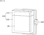
- FIG. 1 is a perspective view showing a storage case of a battery cell according to an embodiment of the present invention
- FIGS. 2 and 3 are perspective views showing a storage case of a battery cell according to another embodiment of the present invention, respectively.
- a storage case of a battery cell may include a case 100 or 110 and a discharge unit 200 or 210.
- the case 100 or 110 accommodates a battery cell 10 or 20 and may include an upper case 101 or 111 of a hollow structure with one opened side and a lower case 102 or 112 of a hollow structure in which the side facing the opened side of the upper case 101 or 111 is opened.
- the case 100 or 110 is not limited in shape and size in plan view, and may be adjusted according to the shape and size of the battery cell 10 or 20 accommodated therein.
- the case 100 when the shape of the battery cell 10 accommodated in the case 100 is cylindrical, the case 100 may also be cylindrical according to the shape of the battery cell 10..
- the case 110 when the shape of the battery cell 20 accommodated in the case 110 is a cube or a cuboid, the case 110 may have a cube or a cuboid shape.
- the upper case 101 or 111 may be coupled to seal the battery cell 10 or 20 accommodated in the lower case 102 or 112.
- the upper case 101 or 111 and the lower case 102 or 112 are not particularly limited as long as they can be firmly coupled, but may be coupled by fixing means such as fixing pins, screws, and bolts.
- an O-ring or the like may be further used between the upper case 101 or 111 and the lower case 102 or 112 to increase the coupling force of the upper case 101 or 111 and the lower case 102 or 112.
- the cases 100 and 110 may be formed of a material including a flame retardant material or an insulating material.
- the inner surface of the case 100 or 110 may be an insulating and heat-insulating material, and a material resistant to high temperature and high pressure, and non-limiting examples thereof may be bakelite, teflon, aerosol, or the like.
- the outer surface surrounding the inner surface may be made of a material such as stainless steel or metal.
- the discharge unit 200 or 210 discharges the battery cell 10 or 20 stored in the case 100 or 110, and is electrically connected to the case 100 or 110, but may be disposed outside the case 100 or 110.
- the case 100 or 110 includes connection terminals electrically connected to the positive electrode terminal and the negative electrode terminal of the accommodated battery cell 10 or 20, and the discharge unit 200 or 210 may be electrically connected to the positive electrode terminal and the negative electrode terminal of the battery cell 10 or 20 by connection terminals of the case 100 or 110.
- the discharge unit 200 or 210 may completely discharge the battery cell 10 or 20, thereby preventing fire or explosion due to charged energy of the battery cell 10 or 20.
- the storage case may further include a switch unit (not shown) which is connected to the discharge unit 200 or 210 and controls discharge of the battery cell 10 or 20.
- the switch unit may be configured to be mounted on the discharge unit 200 or 210 to turn on/off the discharge unit 200 or 210 by mechanical movement.
- the switch unit may discharge the battery cell 10 or 20 by turning the discharge unit 200 or 210 into ON state, or may set not to discharge the battery cell 10 or 20 by turning the discharge unit 200 or 210 into OFF state.
- the discharge unit 200 or 210 may be a lighting element.
- the charged voltage of the battery cell 10 or 20 is applied to the lighting element that is the discharge unit 200 or 210, and the lighting element emits light according to the voltage applied thereto and may indicate that the discharge of the battery cell 10 or 20 is performed.
- the lighting element may indicate that the discharge of the battery cell 10 or 20 is completed by not emitting light.
- the lighting device may be one selected from the group consisting of an incandescent lamp, a fluorescent lamp, and a light emitting diode, but is not limited thereto.
- the discharge unit 200 or 210 may be a circuit module including a discharge circuit for discharging the voltage charged in the battery cell 10 or 20.
- the discharge circuit may include a discharge resistor and a discharge switch connected in series to the discharge resistor.
- the circuit module may include a separate controller for controlling the discharge switch, and the controller may control the discharge switch to discharge the battery cell connected to the discharge circuit.
- a separate display unit 300 may be connected to the discharge unit 200, and the display unit 300 may be connected to the positive electrode of the battery cell 10 and the discharge voltage of the battery cell 10 may be applied.
- the charged voltage of the battery cell 10 may be discharged by the circuit module, which is the discharge unit 200, and the discharge voltage of the battery cell 10 may be applied to the display unit 300.
- the display unit 300 may emit light by the voltage applied thereto to indicate that the discharge of the battery cell 10 is currently performed. Thereafter, when the charged voltage of the battery cell 10 is completely discharged, the display unit 300 may indicate that the discharge of the battery cell 10 has been completed by not emitting light.
- the display unit 300 may be one selected from the group consisting of an incandescent lamp, a fluorescent lamp, and a light emitting diode, but is not limited thereto.
- the battery cell 10 or 20 of the present invention may be a secondary battery in which an electrode assembly having a separator interposed between a positive electrode and a negative electrode is sealed in a battery case of a laminate sheet including a metal layer and a resin layer, and such a battery cell may be a lithium secondary battery.
- the lithium secondary battery may be a cylindrical secondary battery, a square secondary battery, a pouch-type secondary battery, etc. according to the appearance of the battery case.
- the electrode assembly may have a structure in which a plurality of electrodes and a plurality of separators are alternately stacked, and may have one structure selected from the group consisting of folding type, stack type, stack-fold type (SNF), and lamination-stack type (LNS).
- folding type stack type
- stack-fold type SNF
- LNS lamination-stack type
- the electrode assembly of the lamination-stack structure may include one or more electrodes having a laminate laminated on one or both surfaces thereof.
- the electrode assembly of the lamination-stack structure may have a structure in which the separator is bonded to one surface of the positive electrode or the negative electrode.
- the separator may be bonded to both sides of the positive electrode or both sides of the negative electrode.
- the positive electrode, the separator and the negative electrode may be bonded to each other in a state where the separator is interposed between the positive electrode and the negative electrode.
- the positive electrode is prepared by applying a mixture of a positive electrode active material, a conductive material and a binder on a positive electrode current collector, followed by drying. If necessary, a filler may be further added to the mixture.
- the conductive material is usually added in an amount of 1 to 30% by weight based on the total weight of the mixture including the positive electrode active material.
- a conductive material is not particularly limited as long as it has electrical conductivity without causing a chemical change in the battery, and examples thereof include graphite such as natural graphite and artificial graphite; carbon black such as carbon black, acetylene black, Ketjen black, channel black, furnace black, lamp black, and summer black; conductive fibers such as carbon fiber and metal fiber; metal powders such as carbon fluoride, aluminum and nickel powder; conductive whiskey such as zinc oxide and potassium titanate; conductive metal oxides such as titanium oxide; and conductive materials such as polyphenylene derivatives and the like, but the present invention is not limited to these examples.
- the binder is added in an amount of 1 to 30% by weight, on the basis of the total weight of the mixture containing the positive electrode active material, as a component that assists in bonding between the active material and the conductive material and bonding to the current collector.
- binders include polyvinylidene fluoride, polyvinyl alcohol, carboxymethylcellulose (CMC), starch, hydroxypropylcellulose, regenerated cellulose, polyvinylpyrrolidone, tetrafluoroethylene, polyethylene, polypropylene, ethylene-propylene-diene terpolymer (EPDM), sulfonated EPDM, styrene butylene rubber, fluorine rubber, various copolymers and the like.
- the filler is optionally used as a component for inhibiting expansion of a positive electrode, and is not particularly limited as long as it is a fibrous material without causing a chemical change in the battery.
- the filler include olefin polymers such as polyethylene and polypropylene; fibrous materials such as glass fibers and carbon fibers.
- the negative electrode may be formed by coating a negative electrode active material on a negative electrode collector and drying the negative electrode active material.
- the negative electrode may further include the above-described components.
- the negative electrode active material examples include carbon such as non-graphitized carbon and graphite carbon; metal complex oxide such as Li x Fe 2 O 3 (0 ⁇ x ⁇ 1), Li x WO 2 (0 ⁇ x ⁇ 1), Sn x Me 1-x Me' y O z (Me: Mn, Fe, Pb, Ge; Me': Al, B, P, Si, groups 1, 2, and 3 of the periodic table, halogen; 0 ⁇ x ⁇ 1; 1 ⁇ y ⁇ 3; 1 ⁇ z ⁇ 8); lithium alloy; silicon alloy; tin alloy; metal oxides such as SnO, SnO 2 , PbO, PbO 2 , Pb 2 O 3 , Pb 3 O 4 , Sb 2 O 3 , Sb 2 O 4 , Sb 2 O 5 , GeO, GeO 2 , Bi 2 O 3 , Bi 2 O 4 , and Bi 2 O 5 ; conductive polymers such as polyacetylene; and Li-Co-Ni-based materials.
- metal complex oxide such as Li
- the separator may be formed of an insulating thin film having high ion permeability and mechanical strength.
- the process diameter of the separator is generally between 0.01 and 10 ⁇ m, the thickness may be between 5 and 300 ⁇ m.
- Examples of such a separator include olefin-based polymers such as polypropylene which is chemically resistant and hydrophobic; a sheet or a nonwoven fabric made of glass fiber, polyethylene or the like.
- the electrolyte may also serve as a separator.
- a polar organic electrolyte and a lithium salt-containing non-aqueous electrolyte solution containing lithium may have been injected into an electrode assembly housed inside the battery case.
- the electrolyte may be a non-aqueous electrolyte, an organic solid electrolyte, an inorganic solid electrolyte, or the like.
- Non-limiting examples of the non-aqueous liquid electrolyte include N-methyl-2-pyrrolidinone, propylene carbonate, ethylene carbonate, butylenecarbonate, dimethyl carbonate, diethyl carbonate, gamma-Butyrolactone, 1,2-dimethoxyethane, tetrahydroxyfuran, 2-methyltetrahydrofuran, dimethylsulfoxide, 1,3-dioxolane, formamide, dimethylformamide, dioxolane, acetonitrile, nitromethane, methyl formate, methyl acetate, phosphoric acid triester, trimethoxymethane, dioxolane derivatives, sulfolane, methyl sulfolane, 1,3-dimethyl-2-imidazolidinone, propylene carbonate derivatives, tetrahydrofuran derivatives, ethers, methyl pyrophosphate, ethyl propionate, etc.
- organic solid electrolyte examples include a polymer electrolyte such as a polyethylene derivative, a polyethylene oxide derivative, a polypropylene oxide derivative, a phosphate ester polymer, an agitation lysine, a polyester sulfide, a polyvinyl alcohol, a polyvinylidene fluoride, a polymer including an ionic dissociation group, and the like.
- a polymer electrolyte such as a polyethylene derivative, a polyethylene oxide derivative, a polypropylene oxide derivative, a phosphate ester polymer, an agitation lysine, a polyester sulfide, a polyvinyl alcohol, a polyvinylidene fluoride, a polymer including an ionic dissociation group, and the like.
- Examples of the inorganic solid electrolyte include nitrides, halides, and sulfates of Li such as Li 3 N, Lil, Li 5 NI 2 , Li 3 N-LiI-LiOH, LiSiO 4 , LiSiO 4 -LiI-LiOH, Li 2 SiS 3 , Li 4 SiO 4 , Li 4 SiO 4 -Lil-LiOH, and Li 3 PO 4 -Li 2 S-SiS 2 .
- Li 3 N, Lil, Li 5 NI 2 Li 3 N-LiI-LiOH, LiSiO 4 , LiSiO 4 -LiI-LiOH, Li 2 SiS 3 , Li 4 SiO 4 , Li 4 SiO 4 -Lil-LiOH, and Li 3 PO 4 -Li 2 S-SiS 2 .
- the lithium salt is a substance that is soluble in the non-aqueous electrolyte.
- the examples of the lithium salt include LiCl, LiBr, Lil, LiClO 4 , LiBF 4 , LiB 10 Cl 10 LiPF 6 , LiCF 3 SO 3 , LiCF 3 CO 2 , LiAsF 6 , LiSbF 6 , LiAlCl 4 , CH 3 SO 3 Li, CF 3 SO 3 Li, (CF 3 SO 2 ) 2 NLi, chloroborane lithium, lower aliphatic carboxylic acid lithium, lithium 4-phenylborate, imide and the like.
- pyridine, triethylphosphite, triethanolamine, cyclic ether, ethylenediamine, n-glyme, hexaphosphoric triamide, nitrobenzene derivative, sulfur, quinone imine dye, N-substituted oxazolidinone, N-substituted imidazolidine, ethylene glycol dialkyl ether, ammonium salt, pyrrole, 2-methoxyethanol, aluminum trichloride, etc. may be added to the non-aqueous electrolyte.
- a halogen-containing solvent such as carbon tetrachloride or ethylene trifluoride may be further added to impart nonflammability, or a carbon dioxide gas may be further added to improve high temperature storage characteristics.
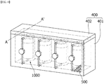
- FIG. 4 is a perspective view showing a storage device of a battery cell according to an embodiment of the present invention
- FIG. 5 is a cross-sectional view illustrating a cross-section taken along line A-A' of FIG. 4
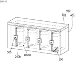
- FIGS. 6 to 8 are perspective views each showing a storage device of a battery cell according to another embodiment of the present invention.
- a storage device of a battery cell may include a chamber 400 or 410 and an exhaust unit 500 or 510.
- the chamber 400 or 410 accommodates storage cases 1000, 1000a or 1000b and may include a chamber body 401 or 411 and a chamber cover 402 or 412.
- the storage cases 1000 of the battery cell are the same as described above, and redundant description will be omitted here.
- the chamber body 401 or 411 may have a hollow structure with an open top.
- the chamber body 401 or 411 is not limited in planar shape and size, and may be a cube or a cuboid in shape and size in which the storage cases 1000 of the battery cell are mounted therein.
- the chamber cover 402 or 412 may be coupled to the opening of the chamber body 401 or 411 to seal the storage cases 1000 mounted in the chamber body 401 or 411.
- the chamber body 401 or 411 and the chamber cover 402 or 412 are not particularly limited as long as the chamber body and the chamber cover can be firmly coupled, but may be coupled by fixing means such as fixing pins, screws, and bolts.
- an O-ring or the like may be further used between the chamber body 401 or 411 and the chamber cover 402 or 412 to increase the coupling force between the chamber body 401 or 411 and the chamber cover 402 or 412.
- the chamber 400 or 401 may be formed of a material including a flame retardant material or an insulating material.
- the inner surface of the chamber 400 or 410 may be an insulating and heat-insulating material, and a material resistant to high temperature and high pressure, and non-limiting examples thereof may be bakelite, teflon, aerosol, or the like.
- the outer surface surrounding the inner surface may be made of a flame retardant material such as stainless steel or metal.
- the chamber 400 has a through hole formed at one side thereof, and the discharge unit 200 of the storage case 1000 may be drawn out of the chamber 400 through the through hole.
- a plurality of partition walls 600 may be formed in the chamber 410 to partition the storage cases 1000. These partition walls 600 prevent a chain reaction to other battery cells due to abnormal operation in some of the battery cells stored in the plurality of storage cases 1000, thereby preventing ignition and explosion due thereto.
- at least one through hole may be formed in each of the partition walls 600. As a result, the partition walls 600 prevent ignition or flame of a battery cell stored in one storage case 1000 from propagating to battery cells stored in other storage cases 1000, and, at the same time, discharge gases by having through holes.
- the exhaust unit 500 or 510 may be formed in at least one portion selected from the group consisting of top, bottom and side surfaces of the chamber 400 or 410. Accordingly, gas generated from the battery cell may be quickly discharged to the outside through the exhaust unit 500 or 510.
- the shape and size of the exhaust unit 500 or 510 are not particularly limited as long as it can exhaust the gas.
- the lighting element which is the discharge unit 200a of the storage case 1000a of the battery cell
- the discharge state of the battery cell stored in the chamber 400 can be checked from the outside, which is an advantage.
- the lighting element, which is the discharge unit 200a may indicate that the discharge of the battery cell is currently performed by emitting light by the voltage of the battery cell applied thereto, and when the charged voltage of the battery cell is applied to the lighting element and the battery cell is completely discharged, the lighting element may indicate that the discharge of the battery cell has been completed by not emitting light.
- the discharge unit 200b of the storage case 1000b of the battery cell may be a circuit module including a discharge circuit for discharging the voltage charged in the battery cell.
- the separate display unit 300 may be connected to the discharge unit 200b, and the display unit 300 may be connected to the positive electrode of the battery cell and the discharge voltage of the battery cell may be applied.
- the charged voltage of the battery cell is discharged by the circuit module, which is the discharge unit 200b, and the discharge voltage of the battery cell may be applied to the display unit 300.
- the display unit 300 may emit light by the voltage applied thereto to indicate that the discharge of the battery cell is currently performed. Thereafter, when the charged voltage of the battery cell is completely discharged, the display unit 300 may indicate that the discharge of the battery cell has been completed by not emitting light.
Landscapes
- Engineering & Computer Science (AREA)
- Chemical & Material Sciences (AREA)
- Chemical Kinetics & Catalysis (AREA)
- Electrochemistry (AREA)
- General Chemical & Material Sciences (AREA)
- Manufacturing & Machinery (AREA)
- Power Engineering (AREA)
- General Engineering & Computer Science (AREA)
- Microelectronics & Electronic Packaging (AREA)
- Mechanical Engineering (AREA)
- Battery Mounting, Suspending (AREA)
Abstract
Description
- This application claims the benefit of priority based on Korean Patent Application No.
10-2018-0160092, filed on December 12, 2018 - The present invention relates to a storage case of a battery cell and a storage device including the same.
- Recently, secondary batteries capable of charging and discharging have been widely used as energy sources of wireless mobile devices. In addition, the secondary battery has attracted attention as an energy source of an electric vehicle, a hybrid electric vehicle, etc., which are proposed as a solution for air pollution of existing gasoline vehicles and diesel vehicles using fossil fuel.
- Small devices such as mobile phones and cameras use small battery packs packed with one secondary battery cell, whereas medium and large devices such as laptops and electric vehicles use medium or large battery packs in which two or more secondary battery cells are connected in parallel and/or in series.
- Such secondary batteries may be classified into lithium ion batteries, lithium ion polymer batteries, lithium polymer batteries, etc., depending on the composition of the electrode and the electrolyte, and among them, the amount of use of lithium-ion polymer batteries that are less likely to leak electrolyte and are easy to manufacture is on the increase.
- On the other hand, the lithium secondary battery has a problem of low stability while having excellent electrical properties. For this reason, many tests have been carried out on products in order to ensure the optimum operating state and stability for secondary batteries.
- Many secondary batteries are stored before the stability test. Such secondary batteries in storage generate heat and gas by causing decomposition reactions of active materials and electrolytes, which are battery components, under abnormal operating conditions such as overcharge, overdischarge, exposure to high temperatures, electrical short circuits, and external shocks. Further, the high temperature and high pressure conditions caused by this may further promote the decomposition reaction, which may cause the air to ignite or explode. In addition, abnormal operation in some of a plurality of secondary batteries may cause a chain reaction to other batteries, and the resulting ignition and explosion may lead to large accidents.
- Thus, in the storage of the secondary battery for the stability test, there is a demand for a method for preventing ignition, explosion, etc. due to external impact, and ensuring stability from the risk of explosion.
- In order to solve the problems of the prior art as described above, an object of the present invention is to provide a storage case of a battery cell that can prevent fire or explosion caused by the charged energy of the battery cell by including a discharge unit for discharging the battery cell.
- In addition, an object of the present invention is to provide a storage device capable of ensuring stability from the risk of explosion, etc. of battery cells by discharging gas that can be generated from battery cell to the outside by including vents while accommodating the storage cases.
- A storage case of a battery cell according to an embodiment of the present invention may include: a case configured to accommodate a battery cell; and a discharge unit configured to be electrically connected to the case and disposed outside the case to discharge the battery cell, wherein the case may include: an upper case of a hollow structure with one opened side; and a lower case having a hollow structure in which a side facing an opening of the upper case is opened.
- The case may include connection terminals electrically connected to a positive electrode terminal and a negative electrode terminal of the battery cell, and the discharge unit may be electrically connected to the positive electrode terminal and the negative electrode terminal of the battery cell by the connection terminals.
- The discharge unit may completely discharge the battery cell.
- The storage case may further include a switch unit which is connected to the battery cell and the discharge unit and controls discharge of the battery cell.
- The discharge unit may be a lighting element, and the lighting element may be one selected from the group consisting of an incandescent lamp, a fluorescent lamp, and a light emitting diode.
- At this time, the battery cell may be discharged by emitting light by the voltage of the battery cell applied to the lighting element.
- On the other hand, the discharge unit may be a circuit module including a discharge circuit for discharging the battery cell.
- Further, the case may be formed of a material including a flame retardant material or an insulating material.
- Further, a storage device of a battery cell according to an embodiment of the present invention may include: a chamber configured to accommodate the storage cases; and exhaust units configured to be formed on at least one portion selected from the group consisting of an upper surface, a lower surface and a side surface of the chamber and discharge gas generated from the battery cell to an outside.
- The chamber may have a through portion formed at one side thereof, and a discharge unit of the storage case may be drawn out to of the chamber through the through portion.
- A plurality of partition walls may be formed inside the chamber to partition the storage cases.
- Herein, at least one through hole may be formed in each of the partition walls.
- Further, the chamber may be formed of a material including a flame retardant material or an insulating material.
- The chamber may include: a chamber body having a hollow structure with an open top; and a chamber cover coupled with an opening of the chamber body to seal the mounted storage case.
- The storage case of the battery cell according to the present invention can prevent the ignition or explosion due to the charged energy possessed by the battery cell by including a discharge unit for discharging the battery cell.
- In addition, The storage device according to the present invention can ensure stability from the risk of explosion, etc. of battery cells by discharging gas that can be generated from battery cell to the outside by including vents while accommodating the storage cases.
-
-
FIG. 1 is a perspective view showing a storage case of a battery cell according to an embodiment of the present invention. -
FIGS. 2 and3 are perspective views showing a storage case of a battery cell according to another embodiment of the present invention, respectively. -
FIG. 4 is a perspective view showing a storage device of a battery cell according to an embodiment of the present invention. -
FIG. 5 is a cross-sectional view illustrating a cross-section taken along line A-A' ofFIG. 4 . -
FIGS. 6 to 8 are perspective views each showing a storage device of a battery cell according to another embodiment of the present invention. - As the inventive concept allows for various changes and numerous embodiments, particular embodiments will be illustrated in the drawings and described in detail in the text. However, this is not intended to limit the present invention to the specific form disclosed, and it should be understood to include all changes, equivalents, and substitutes included in the spirit and scope of the present invention.
- In describing the drawings, similar reference numerals are used for similar elements. In the accompanying drawings, the dimensions of the structures are shown in an enlarged scale for clarity of the invention. Terms such as "first" and "second" may be used to describe various components, but the components should not be limited by the terms. The terms are used only for the purpose of distinguishing one component from another. For example, without departing from the scope of the present invention, a first component may be referred to as a second component, and similarly, the second component may also be referred to as the first component. Singular expressions include plural expressions unless the context clearly indicates otherwise.
- In this application, it should be understood that terms such as "include" or "have" are intended to indicate that there is a feature, number, step, operation, component, part, or a combination thereof described on the specification, and they do not exclude in advance the possibility of the presence or addition of one or more other features or numbers, steps, operations, components, parts or combinations thereof. Also, when a portion such as a layer, a film, an area, a plate, etc. is referred to as being "on" another portion, this includes not only the case where the portion is "directly on" the another portion but also the case where further another portion is interposed therebetween. On the other hand, when a portion such as a layer, a film, an area, a plate, etc. is referred to as being "under" another portion, this includes not only the case where the portion is "directly under" the another portion but also the case where further another portion is interposed therebetween. In addition, to be disposed "on" in the present application may include the case disposed at the bottom as well as the top.
- Hereinafter, an assembled pressurizing jig according to an embodiment of the present invention will be described with reference to the drawings.
-
FIG. 1 is a perspective view showing a storage case of a battery cell according to an embodiment of the present invention, andFIGS. 2 and3 are perspective views showing a storage case of a battery cell according to another embodiment of the present invention, respectively. - A storage case of a battery cell according to an embodiment may include a
case discharge unit - The
case battery cell upper case lower case upper case - The
case battery cell FIG. 1 , when the shape of thebattery cell 10 accommodated in thecase 100 is cylindrical, thecase 100 may also be cylindrical according to the shape of thebattery cell 10.. On the other hand, as shown inFIG. 2 , when the shape of thebattery cell 20 accommodated in thecase 110 is a cube or a cuboid, thecase 110 may have a cube or a cuboid shape. - Meanwhile, the
upper case battery cell lower case upper case lower case upper case lower case upper case lower case - The
cases case - The
discharge unit battery cell case case case case battery cell discharge unit battery cell case discharge unit battery cell battery cell - The storage case may further include a switch unit (not shown) which is connected to the
discharge unit battery cell discharge unit discharge unit battery cell discharge unit battery cell discharge unit - For example, the
discharge unit battery cell discharge unit battery cell battery cell battery cell battery cell - As another example, the
discharge unit battery cell - Meanwhile, as shown in
FIG. 3 , when thedischarge unit 200 is a circuit module, aseparate display unit 300 may be connected to thedischarge unit 200, and thedisplay unit 300 may be connected to the positive electrode of thebattery cell 10 and the discharge voltage of thebattery cell 10 may be applied. Specifically, the charged voltage of thebattery cell 10 may be discharged by the circuit module, which is thedischarge unit 200, and the discharge voltage of thebattery cell 10 may be applied to thedisplay unit 300. Thus, thedisplay unit 300 may emit light by the voltage applied thereto to indicate that the discharge of thebattery cell 10 is currently performed. Thereafter, when the charged voltage of thebattery cell 10 is completely discharged, thedisplay unit 300 may indicate that the discharge of thebattery cell 10 has been completed by not emitting light. In this case, thedisplay unit 300 may be one selected from the group consisting of an incandescent lamp, a fluorescent lamp, and a light emitting diode, but is not limited thereto. - Meanwhile, the
battery cell - Further, the electrode assembly may have a structure in which a plurality of electrodes and a plurality of separators are alternately stacked, and may have one structure selected from the group consisting of folding type, stack type, stack-fold type (SNF), and lamination-stack type (LNS).
- For example, the electrode assembly of the lamination-stack structure may include one or more electrodes having a laminate laminated on one or both surfaces thereof. For example, the electrode assembly of the lamination-stack structure may have a structure in which the separator is bonded to one surface of the positive electrode or the negative electrode. In addition, the separator may be bonded to both sides of the positive electrode or both sides of the negative electrode. In addition, the positive electrode, the separator and the negative electrode may be bonded to each other in a state where the separator is interposed between the positive electrode and the negative electrode.
- The positive electrode is prepared by applying a mixture of a positive electrode active material, a conductive material and a binder on a positive electrode current collector, followed by drying. If necessary, a filler may be further added to the mixture.
- The positive electrode active material may be a layered compound such as lithium cobalt oxide (LiCoO2), lithium nickel oxide (LiNiO2), or a compound substituted with one or more transition metals; lithium manganese oxides such as Ei1+xMn2-xO4 (herein, x is between 0 and 33), LiMnO3, LiMn2O3, and LiMnO2; lithium copper oxide (Li2CuO2); vanadium oxides such as LiV3O8, LiFe3O4, V2O5, and Cu2V2O7; lithium nickel oxide expressed by EiNi1-xMxO2 (herein, M = Co, Mn, Al, Cu, Fe, Mg, B or Ga, and x = 0.01 to 0.3); a lithium manganese compound oxide expressed by LiMn2-xMxO2 (where M = Co, Ni, Fe, Cr, Zn or Ta, x = 0.01 to 0.1) or Li2Mn3MO8 (where M = Fe, Co, Ni, Cu or Zn); LiMn2O4 in which a part of Li is substituted with an alkaline earth metal ion; disulfide compounds; Fe2(MoO4)3, etc., but not limited thereto.

- The conductive material is usually added in an amount of 1 to 30% by weight based on the total weight of the mixture including the positive electrode active material. Such a conductive material is not particularly limited as long as it has electrical conductivity without causing a chemical change in the battery, and examples thereof include graphite such as natural graphite and artificial graphite; carbon black such as carbon black, acetylene black, Ketjen black, channel black, furnace black, lamp black, and summer black; conductive fibers such as carbon fiber and metal fiber; metal powders such as carbon fluoride, aluminum and nickel powder; conductive whiskey such as zinc oxide and potassium titanate; conductive metal oxides such as titanium oxide; and conductive materials such as polyphenylene derivatives and the like, but the present invention is not limited to these examples.
- The binder is added in an amount of 1 to 30% by weight, on the basis of the total weight of the mixture containing the positive electrode active material, as a component that assists in bonding between the active material and the conductive material and bonding to the current collector. Non-limiting examples of such binders include polyvinylidene fluoride, polyvinyl alcohol, carboxymethylcellulose (CMC), starch, hydroxypropylcellulose, regenerated cellulose, polyvinylpyrrolidone, tetrafluoroethylene, polyethylene, polypropylene, ethylene-propylene-diene terpolymer (EPDM), sulfonated EPDM, styrene butylene rubber, fluorine rubber, various copolymers and the like.
- The filler is optionally used as a component for inhibiting expansion of a positive electrode, and is not particularly limited as long as it is a fibrous material without causing a chemical change in the battery. Examples of the filler include olefin polymers such as polyethylene and polypropylene; fibrous materials such as glass fibers and carbon fibers.
- The negative electrode may be formed by coating a negative electrode active material on a negative electrode collector and drying the negative electrode active material. Optionally, the negative electrode may further include the above-described components.
- Examples of the negative electrode active material include carbon such as non-graphitized carbon and graphite carbon; metal complex oxide such as LixFe2O3(0≤x≤1), LixWO2(0≤x≤1), SnxMe1-xMe'yOz (Me: Mn, Fe, Pb, Ge; Me': Al, B, P, Si, groups 1, 2, and 3 of the periodic table, halogen; 0<x≤1; 1<y<3; 1≤z≤8); lithium alloy; silicon alloy; tin alloy; metal oxides such as SnO, SnO2, PbO, PbO2, Pb2O3, Pb3O4, Sb2O3, Sb2O4, Sb2O5, GeO, GeO2, Bi2O3, Bi2O4, and Bi2O5; conductive polymers such as polyacetylene; and Li-Co-Ni-based materials.
- The separator may be formed of an insulating thin film having high ion permeability and mechanical strength. The process diameter of the separator is generally between 0.01 and 10µm, the thickness may be between 5 and 300µm. Examples of such a separator include olefin-based polymers such as polypropylene which is chemically resistant and hydrophobic; a sheet or a nonwoven fabric made of glass fiber, polyethylene or the like. When a solid electrolyte such as a polymer is used as the electrolyte, the solid electrolyte may also serve as a separator.
- Meanwhile, a polar organic electrolyte and a lithium salt-containing non-aqueous electrolyte solution containing lithium may have been injected into an electrode assembly housed inside the battery case. Non-limiting examples of the electrolyte may be a non-aqueous electrolyte, an organic solid electrolyte, an inorganic solid electrolyte, or the like.
- Non-limiting examples of the non-aqueous liquid electrolyte include N-methyl-2-pyrrolidinone, propylene carbonate, ethylene carbonate, butylenecarbonate, dimethyl carbonate, diethyl carbonate, gamma-Butyrolactone, 1,2-dimethoxyethane, tetrahydroxyfuran, 2-methyltetrahydrofuran, dimethylsulfoxide, 1,3-dioxolane, formamide, dimethylformamide, dioxolane, acetonitrile, nitromethane, methyl formate, methyl acetate, phosphoric acid triester, trimethoxymethane, dioxolane derivatives, sulfolane, methyl sulfolane, 1,3-dimethyl-2-imidazolidinone, propylene carbonate derivatives, tetrahydrofuran derivatives, ethers, methyl pyrophosphate, ethyl propionate, etc.
- Examples of the organic solid electrolyte include a polymer electrolyte such as a polyethylene derivative, a polyethylene oxide derivative, a polypropylene oxide derivative, a phosphate ester polymer, an agitation lysine, a polyester sulfide, a polyvinyl alcohol, a polyvinylidene fluoride, a polymer including an ionic dissociation group, and the like.
- Examples of the inorganic solid electrolyte include nitrides, halides, and sulfates of Li such as Li3N, Lil, Li5NI2, Li3N-LiI-LiOH, LiSiO4, LiSiO4-LiI-LiOH, Li2SiS3, Li4SiO4, Li4SiO4-Lil-LiOH, and Li3PO4-Li2S-SiS2.
- The lithium salt is a substance that is soluble in the non-aqueous electrolyte. The examples of the lithium salt include LiCl, LiBr, Lil, LiClO4, LiBF4, LiB10Cl10 LiPF6, LiCF3SO3, LiCF3CO2, LiAsF6, LiSbF6, LiAlCl4, CH3SO3Li, CF3SO3Li, (CF3SO2)2NLi, chloroborane lithium, lower aliphatic carboxylic acid lithium, lithium 4-phenylborate, imide and the like.
- For the purpose of improving charge/discharge characteristics, flame retardancy, etc., pyridine, triethylphosphite, triethanolamine, cyclic ether, ethylenediamine, n-glyme, hexaphosphoric triamide, nitrobenzene derivative, sulfur, quinone imine dye, N-substituted oxazolidinone, N-substituted imidazolidine, ethylene glycol dialkyl ether, ammonium salt, pyrrole, 2-methoxyethanol, aluminum trichloride, etc. may be added to the non-aqueous electrolyte. In some cases, a halogen-containing solvent such as carbon tetrachloride or ethylene trifluoride may be further added to impart nonflammability, or a carbon dioxide gas may be further added to improve high temperature storage characteristics.
- Hereinafter, an storage device of a battery cell according to an embodiment of the present invention will be described with reference to the drawings.
-
FIG. 4 is a perspective view showing a storage device of a battery cell according to an embodiment of the present invention,FIG. 5 is a cross-sectional view illustrating a cross-section taken along line A-A' ofFIG. 4 , andFIGS. 6 to 8 are perspective views each showing a storage device of a battery cell according to another embodiment of the present invention. - A storage device of a battery cell according to an embodiment may include a
chamber exhaust unit - The
chamber storage cases chamber body chamber cover storage cases 1000 of the battery cell are the same as described above, and redundant description will be omitted here. - In this case, the
chamber body chamber body storage cases 1000 of the battery cell are mounted therein. Thechamber cover chamber body storage cases 1000 mounted in thechamber body chamber body chamber cover chamber body chamber cover chamber body chamber cover - The
chamber chamber - In addition, as shown in
FIG. 5 , thechamber 400 has a through hole formed at one side thereof, and thedischarge unit 200 of thestorage case 1000 may be drawn out of thechamber 400 through the through hole. - In addition, as shown in
FIG. 6 , a plurality ofpartition walls 600 may be formed in thechamber 410 to partition thestorage cases 1000. Thesepartition walls 600 prevent a chain reaction to other battery cells due to abnormal operation in some of the battery cells stored in the plurality ofstorage cases 1000, thereby preventing ignition and explosion due thereto. In addition, at least one through hole may be formed in each of thepartition walls 600. As a result, thepartition walls 600 prevent ignition or flame of a battery cell stored in onestorage case 1000 from propagating to battery cells stored inother storage cases 1000, and, at the same time, discharge gases by having through holes. - Meanwhile, the
exhaust unit chamber exhaust unit exhaust unit - Meanwhile, as shown in
FIG. 7 , as the lighting element, which is thedischarge unit 200a of thestorage case 1000a of the battery cell, is drawn out of thechamber 400, the discharge state of the battery cell stored in thechamber 400 can be checked from the outside, which is an advantage. Specifically, the lighting element, which is thedischarge unit 200a, may indicate that the discharge of the battery cell is currently performed by emitting light by the voltage of the battery cell applied thereto, and when the charged voltage of the battery cell is applied to the lighting element and the battery cell is completely discharged, the lighting element may indicate that the discharge of the battery cell has been completed by not emitting light. - As another example, as shown in
FIG. 8 , thedischarge unit 200b of thestorage case 1000b of the battery cell may be a circuit module including a discharge circuit for discharging the voltage charged in the battery cell. In this case, theseparate display unit 300 may be connected to thedischarge unit 200b, and thedisplay unit 300 may be connected to the positive electrode of the battery cell and the discharge voltage of the battery cell may be applied. Thus, the charged voltage of the battery cell is discharged by the circuit module, which is thedischarge unit 200b, and the discharge voltage of the battery cell may be applied to thedisplay unit 300. Thus, thedisplay unit 300 may emit light by the voltage applied thereto to indicate that the discharge of the battery cell is currently performed. Thereafter, when the charged voltage of the battery cell is completely discharged, thedisplay unit 300 may indicate that the discharge of the battery cell has been completed by not emitting light. - Although the above has been described with reference to a preferred embodiment of the present invention, it can be understood that those skilled in the art can make various modifications and changes to the present invention without departing from the spirit and scope of the invention as set forth in the claims below.
- Therefore, the technical scope of the present invention should not be limited to the contents described in the detailed description of the specification but should be defined by the claims.
-
- 1000, 1000a, 1000b:
- storage case
- 100, 110:
- case
- 200, 200a, 200b, 210:
- discharge unit
- 300:
- display unit
- 400, 410:
- chamber
- 500, 510:
- exhaust unit
- 600:
- partition wall
Claims (15)
- A storage case of a battery cell, the storage case comprising:a case configured to accommodate a battery cell; anda discharge unit configured to be electrically connected to the case and disposed outside the case to discharge the battery cell,wherein the case comprises:an upper case of a hollow structure with one opened side; anda lower case having a hollow structure in which a side facing an opening of the upper case is opened.
- The storage case of claim 1, wherein the case includes connection terminals electrically connected to a positive electrode terminal and a negative electrode terminal of the battery cell, and
wherein the discharge unit is electrically connected to the positive electrode terminal and the negative electrode terminal of the battery cell by the connection terminals. - The storage case of claim 1, wherein the discharge unit discharges the battery cell completely.
- The storage case of claim 1, further comprising a switch unit configured to be connected to the battery cell and the discharge unit and control discharge of the battery cell.
- The storage case of claim 1, wherein the discharge unit is a lighting element.
- The storage case of claim 5, wherein the battery cell is discharged by emitting light by the voltage of the battery cell applied to the lighting element.
- The storage case of claim 5, wherein the lighting element is one selected from the group consisting of an incandescent lamp, a fluorescent lamp and a light emitting diode.
- The storage case of claim 1, wherein the discharge unit is a circuit module including a discharge circuit for discharging the battery cell.
- The storage case of claim 1, wherein the case is formed of a material containing a flame retardant material or an insulating material.
- A storage device of a battery cell, the storage device comprising:a chamber configured to accommodate storage cases of the battery cell according to any one of claims 1 to 9; andexhaust units configured to be formed on at least one portion selected from the group consisting of an upper surface, a lower surface and a side surface of the chamber and discharge gas generated from the battery cell to an outside.
- The storage device of claim 10, wherein the chamber has a through portion formed at one side thereof, and a discharge unit of the storage case is drawn out to of the chamber through the through portion.
- The storage device of claim 1, wherein a plurality of partition walls are formed inside the chamber to partition the storage cases.
- The storage device of claim 12, wherein at least one through hole is formed in each of the partition walls.
- The storage device of claim 10, wherein the chamber is formed of a material containing a flame retardant material or an insulating material.
- The storage device of claim 10, wherein the chamber includes: a chamber body having a hollow structure with an open top; and a chamber cover coupled with an opening of the chamber body to seal the mounted storage case.
Applications Claiming Priority (2)
| Application Number | Priority Date | Filing Date | Title |
|---|---|---|---|
| KR1020180160092A KR102497913B1 (en) | 2018-12-12 | 2018-12-12 | Storage case for battery cell and storage device including the same |
| PCT/KR2019/016578 WO2020122474A1 (en) | 2018-12-12 | 2019-11-28 | Battery cell storage case and storage device including same |
Publications (3)
| Publication Number | Publication Date |
|---|---|
| EP3806225A1 true EP3806225A1 (en) | 2021-04-14 |
| EP3806225A4 EP3806225A4 (en) | 2021-09-22 |
| EP3806225B1 EP3806225B1 (en) | 2023-08-23 |
Family
ID=71076981
Family Applications (1)
| Application Number | Title | Priority Date | Filing Date |
|---|---|---|---|
| EP19894799.6A Active EP3806225B1 (en) | 2018-12-12 | 2019-11-28 | Battery cell storage case and storage device including same |
Country Status (6)
| Country | Link |
|---|---|
| US (1) | US11600885B2 (en) |
| EP (1) | EP3806225B1 (en) |
| KR (1) | KR102497913B1 (en) |
| CN (1) | CN112400251B (en) |
| HU (1) | HUE065257T2 (en) |
| WO (1) | WO2020122474A1 (en) |
Families Citing this family (3)
| Publication number | Priority date | Publication date | Assignee | Title |
|---|---|---|---|---|
| US11827110B1 (en) * | 2021-05-24 | 2023-11-28 | Mark Ogram | Protective system for a rechargeable battery |
| KR102684201B1 (en) * | 2022-07-04 | 2024-07-18 | 바테크 주식회사 | Waste battery transport container to protect battery workers |
| KR102724180B1 (en) * | 2023-03-06 | 2024-10-31 | 주식회사 이노벡스 | High-efficiency heat dissipation module and battery cycler having with the same |
Family Cites Families (17)
| Publication number | Priority date | Publication date | Assignee | Title |
|---|---|---|---|---|
| TWI229490B (en) * | 2003-06-20 | 2005-03-11 | Ren-Tang Jang | Structure of power supply for external tool |
| JP5330712B2 (en) * | 2008-02-29 | 2013-10-30 | 三菱重工業株式会社 | Battery storage container and battery pack |
| KR101019220B1 (en) * | 2008-07-15 | 2011-03-03 | 광성전기(주) | Battery with discharge function |
| JP5466906B2 (en) | 2009-09-18 | 2014-04-09 | パナソニック株式会社 | Battery module |
| US8877370B2 (en) | 2010-11-12 | 2014-11-04 | Samsung Sdi Co., Ltd. | Battery pack having a sensor a gas sensor in the cap assembly |
| JP5341156B2 (en) | 2011-09-06 | 2013-11-13 | 三洋電機株式会社 | Power supply |
| US20130343042A1 (en) * | 2012-06-21 | 2013-12-26 | Coast Cutlery Company | Rechargeable flashlight |
| KR101397603B1 (en) | 2012-06-22 | 2014-05-27 | 성진정밀(주) | Impact test device of battery cell |
| JP6332938B2 (en) | 2013-10-24 | 2018-05-30 | 住友重機械搬送システム株式会社 | Charge / discharge inspection equipment |
| KR101800483B1 (en) * | 2013-10-31 | 2017-12-20 | 주식회사 엘지화학 | Jig for charge/discharge battery module and device for charge/discharge battery module using the same |
| KR20170013591A (en) * | 2015-07-28 | 2017-02-07 | 삼성에스디아이 주식회사 | Rechargeable battery including multiful case |
| KR102065126B1 (en) | 2015-11-17 | 2020-01-10 | 주식회사 엘지화학 | Overdischarge test device of secondary battery |
| CN205726608U (en) * | 2016-06-21 | 2016-11-23 | 张帮富 | Inductive lighting lamp with charge function |
| WO2018038369A1 (en) * | 2016-08-25 | 2018-03-01 | 엘지전자 주식회사 | Vacuum |
| KR102256481B1 (en) * | 2017-03-30 | 2021-05-27 | 주식회사 엘지에너지솔루션 | Charging and discharging device for battery cell and inspection system for battery cell comprising the same |
| US20190341585A1 (en) * | 2018-05-07 | 2019-11-07 | Cadenza Innovation, Inc. | Lithium Ion Battery |
| US11448371B2 (en) * | 2019-10-17 | 2022-09-20 | Surefire, Llc | Lighting device power control circuit systems and methods |
-
2018
- 2018-12-12 KR KR1020180160092A patent/KR102497913B1/en active Active
-
2019
- 2019-11-28 CN CN201980045512.0A patent/CN112400251B/en active Active
- 2019-11-28 WO PCT/KR2019/016578 patent/WO2020122474A1/en not_active Ceased
- 2019-11-28 EP EP19894799.6A patent/EP3806225B1/en active Active
- 2019-11-28 HU HUE19894799A patent/HUE065257T2/en unknown
- 2019-11-28 US US17/258,481 patent/US11600885B2/en active Active
Also Published As
| Publication number | Publication date |
|---|---|
| EP3806225A4 (en) | 2021-09-22 |
| KR20200072185A (en) | 2020-06-22 |
| US11600885B2 (en) | 2023-03-07 |
| WO2020122474A1 (en) | 2020-06-18 |
| US20210234224A1 (en) | 2021-07-29 |
| CN112400251A (en) | 2021-02-23 |
| EP3806225B1 (en) | 2023-08-23 |
| HUE065257T2 (en) | 2024-05-28 |
| KR102497913B1 (en) | 2023-02-09 |
| CN112400251B (en) | 2024-05-14 |
Similar Documents
| Publication | Publication Date | Title |
|---|---|---|
| KR101636378B1 (en) | Module Housing for Unit Module Having Heat Radiation Structure and Battery Module Comprising the Same | |
| KR102313058B1 (en) | Secondary Battery Cell with Less Modification of External Form of Battery Case | |
| KR101833540B1 (en) | Battery Cell Having Means For Venting The Gas | |
| KR20170084789A (en) | Safety Member for Battery Cell and Battery Pack Comprising the Same | |
| KR101794939B1 (en) | Battery Cell Comprising Electrode Assemblies of Different Size and Method for Preparing the Same | |
| KR20180081288A (en) | Pouch-typed Battery Cell Comprising Electrode Lead Having Current Breaking Function | |
| KR101751011B1 (en) | Test Device for Battery Cell | |
| KR101414334B1 (en) | Electrochemical cell having high voltage and preparation method the same | |
| EP3806225B1 (en) | Battery cell storage case and storage device including same | |
| KR20100082704A (en) | Pouch type secondary battery having enhanced stability | |
| KR20180106073A (en) | Battery Cell Comprising Extended Terrace Part | |
| KR20170072525A (en) | Method of Manufacturing Cylindrical Battery Cell Comprising Insulating Member | |
| KR101750089B1 (en) | Top Cap For Plasmatic Battery And Battery Pack Comprising the Same | |
| KR101726755B1 (en) | Top Plate For Plasmatic Battery And Battery Pack Comprising the Same | |
| KR101631124B1 (en) | Secondary Battery Having Member for Temperature Measurement | |
| KR101617420B1 (en) | Battery Pack Having Member for Measurement of Cell Voltage | |
| KR101671386B1 (en) | Method of Secondary Battery Using Protective Case | |
| KR20180050842A (en) | Pouch-typed Battery Cell Comprising Electrode Tab and Lead Having Current Breaking Function | |
| EP2871704B1 (en) | Battery module including led device on pcb | |
| KR20160131360A (en) | Battery Pack Containing Cap Members | |
| KR20180047325A (en) | Protection Circuit Board Capable of Easily Checking Welded State between Electrode Terminal and Connection Part thereof and Secondary Battery Pack Comprising the Same | |
| KR20170094646A (en) | Battery Pack Having Battery Cells Integrally Formed in Perpendicular Array | |
| KR20160112417A (en) | Battery Pack Having Overcharge Protection Structure | |
| KR101798929B1 (en) | Battery Case Having Label for Reinforcement and Secondary Battery Comprising the Same | |
| KR102019399B1 (en) | Pouch-typed Battery Cell Having Separation Guide Portion |
Legal Events
| Date | Code | Title | Description |
|---|---|---|---|
| STAA | Information on the status of an ep patent application or granted ep patent |
Free format text: STATUS: THE INTERNATIONAL PUBLICATION HAS BEEN MADE |
|
| PUAI | Public reference made under article 153(3) epc to a published international application that has entered the european phase |
Free format text: ORIGINAL CODE: 0009012 |
|
| STAA | Information on the status of an ep patent application or granted ep patent |
Free format text: STATUS: REQUEST FOR EXAMINATION WAS MADE |
|
| 17P | Request for examination filed |
Effective date: 20210108 |
|
| AK | Designated contracting states |
Kind code of ref document: A1 Designated state(s): AL AT BE BG CH CY CZ DE DK EE ES FI FR GB GR HR HU IE IS IT LI LT LU LV MC MK MT NL NO PL PT RO RS SE SI SK SM TR |
|
| AX | Request for extension of the european patent |
Extension state: BA ME |
|
| A4 | Supplementary search report drawn up and despatched |
Effective date: 20210819 |
|
| RIC1 | Information provided on ipc code assigned before grant |
Ipc: F21V 15/01 20060101ALI20210813BHEP Ipc: B65D 77/22 20060101ALI20210813BHEP Ipc: H02J 7/00 20060101ALI20210813BHEP Ipc: H01M 6/50 20060101ALI20210813BHEP Ipc: H01M 10/42 20060101AFI20210813BHEP |
|
| RAP1 | Party data changed (applicant data changed or rights of an application transferred) |
Owner name: LG ENERGY SOLUTION LTD. |
|
| DAV | Request for validation of the european patent (deleted) | ||
| DAX | Request for extension of the european patent (deleted) | ||
| RAP3 | Party data changed (applicant data changed or rights of an application transferred) |
Owner name: LG ENERGY SOLUTION, LTD. |
|
| GRAP | Despatch of communication of intention to grant a patent |
Free format text: ORIGINAL CODE: EPIDOSNIGR1 |
|
| STAA | Information on the status of an ep patent application or granted ep patent |
Free format text: STATUS: GRANT OF PATENT IS INTENDED |
|
| INTG | Intention to grant announced |
Effective date: 20230321 |
|
| P01 | Opt-out of the competence of the unified patent court (upc) registered |
Effective date: 20230516 |
|
| GRAS | Grant fee paid |
Free format text: ORIGINAL CODE: EPIDOSNIGR3 |
|
| GRAA | (expected) grant |
Free format text: ORIGINAL CODE: 0009210 |
|
| STAA | Information on the status of an ep patent application or granted ep patent |
Free format text: STATUS: THE PATENT HAS BEEN GRANTED |
|
| AK | Designated contracting states |
Kind code of ref document: B1 Designated state(s): AL AT BE BG CH CY CZ DE DK EE ES FI FR GB GR HR HU IE IS IT LI LT LU LV MC MK MT NL NO PL PT RO RS SE SI SK SM TR |
|
| REG | Reference to a national code |
Ref country code: GB Ref legal event code: FG4D |
|
| REG | Reference to a national code |
Ref country code: CH Ref legal event code: EP |
|
| REG | Reference to a national code |
Ref country code: IE Ref legal event code: FG4D |
|
| REG | Reference to a national code |
Ref country code: DE Ref legal event code: R096 Ref document number: 602019035854 Country of ref document: DE |
|
| REG | Reference to a national code |
Ref country code: LT Ref legal event code: MG9D |
|
| REG | Reference to a national code |
Ref country code: NL Ref legal event code: MP Effective date: 20230823 |
|
| REG | Reference to a national code |
Ref country code: AT Ref legal event code: MK05 Ref document number: 1603649 Country of ref document: AT Kind code of ref document: T Effective date: 20230823 |
|
| PG25 | Lapsed in a contracting state [announced via postgrant information from national office to epo] |
Ref country code: GR Free format text: LAPSE BECAUSE OF FAILURE TO SUBMIT A TRANSLATION OF THE DESCRIPTION OR TO PAY THE FEE WITHIN THE PRESCRIBED TIME-LIMIT Effective date: 20231124 |
|
| PG25 | Lapsed in a contracting state [announced via postgrant information from national office to epo] |
Ref country code: IS Free format text: LAPSE BECAUSE OF FAILURE TO SUBMIT A TRANSLATION OF THE DESCRIPTION OR TO PAY THE FEE WITHIN THE PRESCRIBED TIME-LIMIT Effective date: 20231223 |
|
| PG25 | Lapsed in a contracting state [announced via postgrant information from national office to epo] |
Ref country code: SE Free format text: LAPSE BECAUSE OF FAILURE TO SUBMIT A TRANSLATION OF THE DESCRIPTION OR TO PAY THE FEE WITHIN THE PRESCRIBED TIME-LIMIT Effective date: 20230823 Ref country code: RS Free format text: LAPSE BECAUSE OF FAILURE TO SUBMIT A TRANSLATION OF THE DESCRIPTION OR TO PAY THE FEE WITHIN THE PRESCRIBED TIME-LIMIT Effective date: 20230823 Ref country code: PT Free format text: LAPSE BECAUSE OF FAILURE TO SUBMIT A TRANSLATION OF THE DESCRIPTION OR TO PAY THE FEE WITHIN THE PRESCRIBED TIME-LIMIT Effective date: 20231226 Ref country code: NO Free format text: LAPSE BECAUSE OF FAILURE TO SUBMIT A TRANSLATION OF THE DESCRIPTION OR TO PAY THE FEE WITHIN THE PRESCRIBED TIME-LIMIT Effective date: 20231123 Ref country code: NL Free format text: LAPSE BECAUSE OF FAILURE TO SUBMIT A TRANSLATION OF THE DESCRIPTION OR TO PAY THE FEE WITHIN THE PRESCRIBED TIME-LIMIT Effective date: 20230823 Ref country code: LV Free format text: LAPSE BECAUSE OF FAILURE TO SUBMIT A TRANSLATION OF THE DESCRIPTION OR TO PAY THE FEE WITHIN THE PRESCRIBED TIME-LIMIT Effective date: 20230823 Ref country code: LT Free format text: LAPSE BECAUSE OF FAILURE TO SUBMIT A TRANSLATION OF THE DESCRIPTION OR TO PAY THE FEE WITHIN THE PRESCRIBED TIME-LIMIT Effective date: 20230823 Ref country code: IS Free format text: LAPSE BECAUSE OF FAILURE TO SUBMIT A TRANSLATION OF THE DESCRIPTION OR TO PAY THE FEE WITHIN THE PRESCRIBED TIME-LIMIT Effective date: 20231223 Ref country code: HR Free format text: LAPSE BECAUSE OF FAILURE TO SUBMIT A TRANSLATION OF THE DESCRIPTION OR TO PAY THE FEE WITHIN THE PRESCRIBED TIME-LIMIT Effective date: 20230823 Ref country code: GR Free format text: LAPSE BECAUSE OF FAILURE TO SUBMIT A TRANSLATION OF THE DESCRIPTION OR TO PAY THE FEE WITHIN THE PRESCRIBED TIME-LIMIT Effective date: 20231124 Ref country code: FI Free format text: LAPSE BECAUSE OF FAILURE TO SUBMIT A TRANSLATION OF THE DESCRIPTION OR TO PAY THE FEE WITHIN THE PRESCRIBED TIME-LIMIT Effective date: 20230823 Ref country code: AT Free format text: LAPSE BECAUSE OF FAILURE TO SUBMIT A TRANSLATION OF THE DESCRIPTION OR TO PAY THE FEE WITHIN THE PRESCRIBED TIME-LIMIT Effective date: 20230823 |
|
| PG25 | Lapsed in a contracting state [announced via postgrant information from national office to epo] |
Ref country code: PL Free format text: LAPSE BECAUSE OF FAILURE TO SUBMIT A TRANSLATION OF THE DESCRIPTION OR TO PAY THE FEE WITHIN THE PRESCRIBED TIME-LIMIT Effective date: 20230823 |
|
| PG25 | Lapsed in a contracting state [announced via postgrant information from national office to epo] |
Ref country code: ES Free format text: LAPSE BECAUSE OF FAILURE TO SUBMIT A TRANSLATION OF THE DESCRIPTION OR TO PAY THE FEE WITHIN THE PRESCRIBED TIME-LIMIT Effective date: 20230823 |
|
| PG25 | Lapsed in a contracting state [announced via postgrant information from national office to epo] |
Ref country code: SM Free format text: LAPSE BECAUSE OF FAILURE TO SUBMIT A TRANSLATION OF THE DESCRIPTION OR TO PAY THE FEE WITHIN THE PRESCRIBED TIME-LIMIT Effective date: 20230823 Ref country code: RO Free format text: LAPSE BECAUSE OF FAILURE TO SUBMIT A TRANSLATION OF THE DESCRIPTION OR TO PAY THE FEE WITHIN THE PRESCRIBED TIME-LIMIT Effective date: 20230823 Ref country code: ES Free format text: LAPSE BECAUSE OF FAILURE TO SUBMIT A TRANSLATION OF THE DESCRIPTION OR TO PAY THE FEE WITHIN THE PRESCRIBED TIME-LIMIT Effective date: 20230823 Ref country code: EE Free format text: LAPSE BECAUSE OF FAILURE TO SUBMIT A TRANSLATION OF THE DESCRIPTION OR TO PAY THE FEE WITHIN THE PRESCRIBED TIME-LIMIT Effective date: 20230823 Ref country code: DK Free format text: LAPSE BECAUSE OF FAILURE TO SUBMIT A TRANSLATION OF THE DESCRIPTION OR TO PAY THE FEE WITHIN THE PRESCRIBED TIME-LIMIT Effective date: 20230823 Ref country code: CZ Free format text: LAPSE BECAUSE OF FAILURE TO SUBMIT A TRANSLATION OF THE DESCRIPTION OR TO PAY THE FEE WITHIN THE PRESCRIBED TIME-LIMIT Effective date: 20230823 Ref country code: SK Free format text: LAPSE BECAUSE OF FAILURE TO SUBMIT A TRANSLATION OF THE DESCRIPTION OR TO PAY THE FEE WITHIN THE PRESCRIBED TIME-LIMIT Effective date: 20230823 |
|
| REG | Reference to a national code |
Ref country code: DE Ref legal event code: R097 Ref document number: 602019035854 Country of ref document: DE |
|
| REG | Reference to a national code |
Ref country code: HU Ref legal event code: AG4A Ref document number: E065257 Country of ref document: HU |
|
| PG25 | Lapsed in a contracting state [announced via postgrant information from national office to epo] |
Ref country code: IT Free format text: LAPSE BECAUSE OF FAILURE TO SUBMIT A TRANSLATION OF THE DESCRIPTION OR TO PAY THE FEE WITHIN THE PRESCRIBED TIME-LIMIT Effective date: 20230823 |
|
| PLBE | No opposition filed within time limit |
Free format text: ORIGINAL CODE: 0009261 |
|
| STAA | Information on the status of an ep patent application or granted ep patent |
Free format text: STATUS: NO OPPOSITION FILED WITHIN TIME LIMIT |
|
| REG | Reference to a national code |
Ref country code: CH Ref legal event code: PL |
|
| PG25 | Lapsed in a contracting state [announced via postgrant information from national office to epo] |
Ref country code: MC Free format text: LAPSE BECAUSE OF FAILURE TO SUBMIT A TRANSLATION OF THE DESCRIPTION OR TO PAY THE FEE WITHIN THE PRESCRIBED TIME-LIMIT Effective date: 20230823 |
|
| PG25 | Lapsed in a contracting state [announced via postgrant information from national office to epo] |
Ref country code: LU Free format text: LAPSE BECAUSE OF NON-PAYMENT OF DUE FEES Effective date: 20231128 |
|
| PG25 | Lapsed in a contracting state [announced via postgrant information from national office to epo] |
Ref country code: CH Free format text: LAPSE BECAUSE OF NON-PAYMENT OF DUE FEES Effective date: 20231130 |
|
| 26N | No opposition filed |
Effective date: 20240524 |
|
| PG25 | Lapsed in a contracting state [announced via postgrant information from national office to epo] |
Ref country code: MC Free format text: LAPSE BECAUSE OF FAILURE TO SUBMIT A TRANSLATION OF THE DESCRIPTION OR TO PAY THE FEE WITHIN THE PRESCRIBED TIME-LIMIT Effective date: 20230823 Ref country code: LU Free format text: LAPSE BECAUSE OF NON-PAYMENT OF DUE FEES Effective date: 20231128 Ref country code: CH Free format text: LAPSE BECAUSE OF NON-PAYMENT OF DUE FEES Effective date: 20231130 Ref country code: SI Free format text: LAPSE BECAUSE OF FAILURE TO SUBMIT A TRANSLATION OF THE DESCRIPTION OR TO PAY THE FEE WITHIN THE PRESCRIBED TIME-LIMIT Effective date: 20230823 |
|
| REG | Reference to a national code |
Ref country code: BE Ref legal event code: MM Effective date: 20231130 |
|
| REG | Reference to a national code |
Ref country code: IE Ref legal event code: MM4A |
|
| PG25 | Lapsed in a contracting state [announced via postgrant information from national office to epo] |
Ref country code: IE Free format text: LAPSE BECAUSE OF NON-PAYMENT OF DUE FEES Effective date: 20231128 |
|
| PG25 | Lapsed in a contracting state [announced via postgrant information from national office to epo] |
Ref country code: BE Free format text: LAPSE BECAUSE OF NON-PAYMENT OF DUE FEES Effective date: 20231130 |
|
| PG25 | Lapsed in a contracting state [announced via postgrant information from national office to epo] |
Ref country code: IE Free format text: LAPSE BECAUSE OF NON-PAYMENT OF DUE FEES Effective date: 20231128 Ref country code: BE Free format text: LAPSE BECAUSE OF NON-PAYMENT OF DUE FEES Effective date: 20231130 |
|
| PG25 | Lapsed in a contracting state [announced via postgrant information from national office to epo] |
Ref country code: BG Free format text: LAPSE BECAUSE OF FAILURE TO SUBMIT A TRANSLATION OF THE DESCRIPTION OR TO PAY THE FEE WITHIN THE PRESCRIBED TIME-LIMIT Effective date: 20230823 |
|
| PG25 | Lapsed in a contracting state [announced via postgrant information from national office to epo] |
Ref country code: BG Free format text: LAPSE BECAUSE OF FAILURE TO SUBMIT A TRANSLATION OF THE DESCRIPTION OR TO PAY THE FEE WITHIN THE PRESCRIBED TIME-LIMIT Effective date: 20230823 |
|
| PG25 | Lapsed in a contracting state [announced via postgrant information from national office to epo] |
Ref country code: CY Free format text: LAPSE BECAUSE OF FAILURE TO SUBMIT A TRANSLATION OF THE DESCRIPTION OR TO PAY THE FEE WITHIN THE PRESCRIBED TIME-LIMIT; INVALID AB INITIO Effective date: 20191128 |
|
| PG25 | Lapsed in a contracting state [announced via postgrant information from national office to epo] |
Ref country code: TR Free format text: LAPSE BECAUSE OF FAILURE TO SUBMIT A TRANSLATION OF THE DESCRIPTION OR TO PAY THE FEE WITHIN THE PRESCRIBED TIME-LIMIT Effective date: 20230823 |
|
| PGFP | Annual fee paid to national office [announced via postgrant information from national office to epo] |
Ref country code: HU Payment date: 20251127 Year of fee payment: 7 |
|
| PGFP | Annual fee paid to national office [announced via postgrant information from national office to epo] |
Ref country code: DE Payment date: 20251020 Year of fee payment: 7 |
|
| PGFP | Annual fee paid to national office [announced via postgrant information from national office to epo] |
Ref country code: GB Payment date: 20251023 Year of fee payment: 7 |
|
| PGFP | Annual fee paid to national office [announced via postgrant information from national office to epo] |
Ref country code: FR Payment date: 20251021 Year of fee payment: 7 |