EP3806212A1 - Method for controlling catalyst combustion device, and catalyst combustion system - Google Patents
Method for controlling catalyst combustion device, and catalyst combustion system Download PDFInfo
- Publication number
- EP3806212A1 EP3806212A1 EP18920491.0A EP18920491A EP3806212A1 EP 3806212 A1 EP3806212 A1 EP 3806212A1 EP 18920491 A EP18920491 A EP 18920491A EP 3806212 A1 EP3806212 A1 EP 3806212A1
- Authority
- EP
- European Patent Office
- Prior art keywords
- catalytic combustion
- combustion apparatus
- fuel
- heater
- injection amount
- Prior art date
- Legal status (The legal status is an assumption and is not a legal conclusion. Google has not performed a legal analysis and makes no representation as to the accuracy of the status listed.)
- Granted
Links
Images



Classifications
-
- F—MECHANICAL ENGINEERING; LIGHTING; HEATING; WEAPONS; BLASTING
- F23—COMBUSTION APPARATUS; COMBUSTION PROCESSES
- F23N—REGULATING OR CONTROLLING COMBUSTION
- F23N1/00—Regulating fuel supply
- F23N1/02—Regulating fuel supply conjointly with air supply
- F23N1/022—Regulating fuel supply conjointly with air supply using electronic means
-
- H—ELECTRICITY
- H01—ELECTRIC ELEMENTS
- H01M—PROCESSES OR MEANS, e.g. BATTERIES, FOR THE DIRECT CONVERSION OF CHEMICAL ENERGY INTO ELECTRICAL ENERGY
- H01M8/00—Fuel cells; Manufacture thereof
- H01M8/04—Auxiliary arrangements, e.g. for control of pressure or for circulation of fluids
- H01M8/04007—Auxiliary arrangements, e.g. for control of pressure or for circulation of fluids related to heat exchange
- H01M8/04014—Heat exchange using gaseous fluids; Heat exchange by combustion of reactants
-
- F—MECHANICAL ENGINEERING; LIGHTING; HEATING; WEAPONS; BLASTING
- F23—COMBUSTION APPARATUS; COMBUSTION PROCESSES
- F23C—METHODS OR APPARATUS FOR COMBUSTION USING FLUID FUEL OR SOLID FUEL SUSPENDED IN A CARRIER GAS OR AIR
- F23C13/00—Apparatus in which combustion takes place in the presence of catalytic material
-
- F—MECHANICAL ENGINEERING; LIGHTING; HEATING; WEAPONS; BLASTING
- F23—COMBUSTION APPARATUS; COMBUSTION PROCESSES
- F23D—BURNERS
- F23D11/00—Burners using a direct spraying action of liquid droplets or vaporised liquid into the combustion space
- F23D11/24—Burners using a direct spraying action of liquid droplets or vaporised liquid into the combustion space by pressurisation of the fuel before a nozzle through which it is sprayed by a substantial pressure reduction into a space
- F23D11/26—Burners using a direct spraying action of liquid droplets or vaporised liquid into the combustion space by pressurisation of the fuel before a nozzle through which it is sprayed by a substantial pressure reduction into a space with provision for varying the rate at which the fuel is sprayed
-
- F—MECHANICAL ENGINEERING; LIGHTING; HEATING; WEAPONS; BLASTING
- F23—COMBUSTION APPARATUS; COMBUSTION PROCESSES
- F23D—BURNERS
- F23D11/00—Burners using a direct spraying action of liquid droplets or vaporised liquid into the combustion space
- F23D11/36—Details
- F23D11/44—Preheating devices; Vaporising devices
- F23D11/441—Vaporising devices incorporated with burners
- F23D11/448—Vaporising devices incorporated with burners heated by electrical means
-
- F—MECHANICAL ENGINEERING; LIGHTING; HEATING; WEAPONS; BLASTING
- F23—COMBUSTION APPARATUS; COMBUSTION PROCESSES
- F23D—BURNERS
- F23D5/00—Burners in which liquid fuel evaporates in the combustion space, with or without chemical conversion of evaporated fuel
- F23D5/12—Details
- F23D5/126—Catalytic elements
-
- F—MECHANICAL ENGINEERING; LIGHTING; HEATING; WEAPONS; BLASTING
- F23—COMBUSTION APPARATUS; COMBUSTION PROCESSES
- F23D—BURNERS
- F23D5/00—Burners in which liquid fuel evaporates in the combustion space, with or without chemical conversion of evaporated fuel
- F23D5/12—Details
- F23D5/18—Preheating devices
-
- F—MECHANICAL ENGINEERING; LIGHTING; HEATING; WEAPONS; BLASTING
- F23—COMBUSTION APPARATUS; COMBUSTION PROCESSES
- F23K—FEEDING FUEL TO COMBUSTION APPARATUS
- F23K5/00—Feeding or distributing other fuel to combustion apparatus
- F23K5/02—Liquid fuel
- F23K5/08—Preparation of fuel
- F23K5/10—Mixing with other fluids
-
- F—MECHANICAL ENGINEERING; LIGHTING; HEATING; WEAPONS; BLASTING
- F23—COMBUSTION APPARATUS; COMBUSTION PROCESSES
- F23N—REGULATING OR CONTROLLING COMBUSTION
- F23N1/00—Regulating fuel supply
- F23N1/002—Regulating fuel supply using electronic means
-
- F—MECHANICAL ENGINEERING; LIGHTING; HEATING; WEAPONS; BLASTING
- F23—COMBUSTION APPARATUS; COMBUSTION PROCESSES
- F23N—REGULATING OR CONTROLLING COMBUSTION
- F23N1/00—Regulating fuel supply
- F23N1/005—Regulating fuel supply using electrical or electromechanical means
-
- H—ELECTRICITY
- H01—ELECTRIC ELEMENTS
- H01M—PROCESSES OR MEANS, e.g. BATTERIES, FOR THE DIRECT CONVERSION OF CHEMICAL ENERGY INTO ELECTRICAL ENERGY
- H01M8/00—Fuel cells; Manufacture thereof
- H01M8/04—Auxiliary arrangements, e.g. for control of pressure or for circulation of fluids
- H01M8/04007—Auxiliary arrangements, e.g. for control of pressure or for circulation of fluids related to heat exchange
- H01M8/04059—Evaporative processes for the cooling of a fuel cell
-
- H—ELECTRICITY
- H01—ELECTRIC ELEMENTS
- H01M—PROCESSES OR MEANS, e.g. BATTERIES, FOR THE DIRECT CONVERSION OF CHEMICAL ENERGY INTO ELECTRICAL ENERGY
- H01M8/00—Fuel cells; Manufacture thereof
- H01M8/06—Combination of fuel cells with means for production of reactants or for treatment of residues
- H01M8/0606—Combination of fuel cells with means for production of reactants or for treatment of residues with means for production of gaseous reactants
- H01M8/0612—Combination of fuel cells with means for production of reactants or for treatment of residues with means for production of gaseous reactants from carbon-containing material
- H01M8/0618—Reforming processes, e.g. autothermal, partial oxidation or steam reforming
-
- F—MECHANICAL ENGINEERING; LIGHTING; HEATING; WEAPONS; BLASTING
- F23—COMBUSTION APPARATUS; COMBUSTION PROCESSES
- F23C—METHODS OR APPARATUS FOR COMBUSTION USING FLUID FUEL OR SOLID FUEL SUSPENDED IN A CARRIER GAS OR AIR
- F23C2700/00—Special arrangements for combustion apparatus using fluent fuel
- F23C2700/02—Combustion apparatus using liquid fuel
-
- F—MECHANICAL ENGINEERING; LIGHTING; HEATING; WEAPONS; BLASTING
- F23—COMBUSTION APPARATUS; COMBUSTION PROCESSES
- F23C—METHODS OR APPARATUS FOR COMBUSTION USING FLUID FUEL OR SOLID FUEL SUSPENDED IN A CARRIER GAS OR AIR
- F23C2900/00—Special features of, or arrangements for combustion apparatus using fluid fuels or solid fuels suspended in air; Combustion processes therefor
- F23C2900/13001—Details of catalytic combustors
-
- F—MECHANICAL ENGINEERING; LIGHTING; HEATING; WEAPONS; BLASTING
- F23—COMBUSTION APPARATUS; COMBUSTION PROCESSES
- F23K—FEEDING FUEL TO COMBUSTION APPARATUS
- F23K2300/00—Pretreatment and supply of liquid fuel
- F23K2300/10—Pretreatment
- F23K2300/103—Mixing with other fluids
-
- F—MECHANICAL ENGINEERING; LIGHTING; HEATING; WEAPONS; BLASTING
- F23—COMBUSTION APPARATUS; COMBUSTION PROCESSES
- F23N—REGULATING OR CONTROLLING COMBUSTION
- F23N2225/00—Measuring
- F23N2225/08—Measuring temperature
- F23N2225/16—Measuring temperature burner temperature
-
- F—MECHANICAL ENGINEERING; LIGHTING; HEATING; WEAPONS; BLASTING
- F23—COMBUSTION APPARATUS; COMBUSTION PROCESSES
- F23N—REGULATING OR CONTROLLING COMBUSTION
- F23N2237/00—Controlling
- F23N2237/12—Controlling catalytic burners
-
- F—MECHANICAL ENGINEERING; LIGHTING; HEATING; WEAPONS; BLASTING
- F23—COMBUSTION APPARATUS; COMBUSTION PROCESSES
- F23N—REGULATING OR CONTROLLING COMBUSTION
- F23N2237/00—Controlling
- F23N2237/14—Controlling burners with gasification or vaporizer elements
-
- H—ELECTRICITY
- H01—ELECTRIC ELEMENTS
- H01M—PROCESSES OR MEANS, e.g. BATTERIES, FOR THE DIRECT CONVERSION OF CHEMICAL ENERGY INTO ELECTRICAL ENERGY
- H01M2250/00—Fuel cells for particular applications; Specific features of fuel cell system
- H01M2250/20—Fuel cells in motive systems, e.g. vehicle, ship, plane
-
- H—ELECTRICITY
- H01—ELECTRIC ELEMENTS
- H01M—PROCESSES OR MEANS, e.g. BATTERIES, FOR THE DIRECT CONVERSION OF CHEMICAL ENERGY INTO ELECTRICAL ENERGY
- H01M8/00—Fuel cells; Manufacture thereof
- H01M8/04—Auxiliary arrangements, e.g. for control of pressure or for circulation of fluids
- H01M8/04007—Auxiliary arrangements, e.g. for control of pressure or for circulation of fluids related to heat exchange
- H01M8/04014—Heat exchange using gaseous fluids; Heat exchange by combustion of reactants
- H01M8/04022—Heating by combustion
-
- H—ELECTRICITY
- H01—ELECTRIC ELEMENTS
- H01M—PROCESSES OR MEANS, e.g. BATTERIES, FOR THE DIRECT CONVERSION OF CHEMICAL ENERGY INTO ELECTRICAL ENERGY
- H01M8/00—Fuel cells; Manufacture thereof
- H01M8/04—Auxiliary arrangements, e.g. for control of pressure or for circulation of fluids
- H01M8/04298—Processes for controlling fuel cells or fuel cell systems
- H01M8/04694—Processes for controlling fuel cells or fuel cell systems characterised by variables to be controlled
- H01M8/04701—Temperature
- H01M8/04708—Temperature of fuel cell reactants
-
- Y—GENERAL TAGGING OF NEW TECHNOLOGICAL DEVELOPMENTS; GENERAL TAGGING OF CROSS-SECTIONAL TECHNOLOGIES SPANNING OVER SEVERAL SECTIONS OF THE IPC; TECHNICAL SUBJECTS COVERED BY FORMER USPC CROSS-REFERENCE ART COLLECTIONS [XRACs] AND DIGESTS
- Y02—TECHNOLOGIES OR APPLICATIONS FOR MITIGATION OR ADAPTATION AGAINST CLIMATE CHANGE
- Y02E—REDUCTION OF GREENHOUSE GAS [GHG] EMISSIONS, RELATED TO ENERGY GENERATION, TRANSMISSION OR DISTRIBUTION
- Y02E60/00—Enabling technologies; Technologies with a potential or indirect contribution to GHG emissions mitigation
- Y02E60/30—Hydrogen technology
- Y02E60/50—Fuel cells
Definitions
- the present invention relates to a method for controlling a catalytic combustion apparatus having a heater and a catalytic combustion system.
- JP2013-253004A discloses a technique regarding a reformer in which after a heater is electrically energized, the energization of the heater is released if each of temperature of an oxidizing region and a reforming region of a catalytic converter becomes equal to or higher than a predetermined temperature, and then hydrogen-based fuel is supplied.
- the present invention has been made in view of the problem and an object of the present invention is to provide a control method and a catalytic combustion system for activating a catalytic combustion apparatus at an early stage.
- a method for controlling a catalytic combustion apparatus having a heater capable of heating fuel to be supplied to a catalyst includes a step of supplying oxidant gas to the catalytic combustion apparatus, and an injection step of injecting the fuel into the catalytic combustion apparatus.
- the injection step then includes an electric power feeding step of supplying electric power to the heater, and a setting step of setting an injection amount of the fuel to be injected into the catalytic combustion apparatus in response to output of the heater.
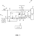
- FIG. 1 is a configuration diagram showing an example of a configuration of a fuel cell system 100 according to an embodiment of the present invention.
- the fuel cell system 100 allows a fuel cell 10 to generate electric power by supplying fuel gas and oxidant gas to the fuel cell 10.
- the fuel cell system 100 is mounted on a mobile body such as a vehicle, an airplane, or a ship. According to this present embodiment, the fuel cell system 100 is mounted on a vehicle such as a hybrid vehicle or an electric vehicle.
- the fuel cell system 100 includes the fuel cell 10, an oxidant supply device 20, a fuel supply device 30, a heating device 40, and a controller 50.
- the fuel cell 10 generates electric power, being supplied with fuel gas and the oxidant gas.
- the fuel cell 10 is realized by a fuel cell such as a solid oxide type or a solid polymer type.
- the fuel cell 10 of the present embodiment is laminated cells in which a plurality of a single solid oxide type fuel cell is stacked.
- the fuel cell 10 generates electric power by a chemical reaction between the fuel gas and the oxidant gas under a temperature of the fuel cell 10 arriving at a range of 600° C. to 700° C.
- the oxidant supply device 20 supplies the oxidant gas to the fuel cell 10, the oxidant gas required for electric power generation of the fuel cell 10.
- the oxidant supply device 20 includes an oxidant supply passage 21, a compressor 22, and an oxidant heat exchanger 23.
- the oxidant supply passage 21 is a passage for supplying the oxidant gas to the fuel cell 10.
- one end of the oxidant supply passage 21 communicates with the outside air, and the other end thereof is connected to an oxidant inlet hole of the fuel cell 10.
- the compressor 22 is an actuator provided in the oxidant supply passage 21.
- the compressor 22 sucks the air as the oxidant gas from the one end of the oxidant supply passage 21.
- the compressor 22 compresses the air and then supplies the air to the fuel cell 10 through the oxidant supply passage 21.
- the compressor 22 is used as the actuator in the present embodiment. Instead of the compressor 22, a blower or the like may be used.
- the oxidant heat exchanger 23 is a heat exchanger that heats the oxidant gas to be supplied to the fuel cell 10, the heating of the oxidant gas is for warming up the fuel cell 10.
- the oxidant heat exchanger 23 performs heat exchange between the high-temperature exhaust gas generated by the heating device 40 and the air from the compressor 22.
- the oxidant heat exchanger 23 outputs the air to the fuel cell 10, the air having been heated by the heat exchange.
- the fuel supply device 30 supplies the fuel gas to the fuel cell 10, the fuel gas required for electric power generation of the fuel cell 10.
- the fuel supply device 30 includes a fuel supply passage 31, a raw fuel tank 32, a fuel pump 33, an injector 34, an evaporator 35, a heater 36, and a reformer 37.
- the fuel supply passage 31 is a passage for supplying the fuel gas to the fuel cell 10.
- one end of the fuel supply passage 31 is connected to the raw fuel tank 32, the other end thereof is connected to a fuel inlet hole of the fuel cell 10.
- the raw fuel tank 32 stores raw fuel required for production of the fuel gas.
- an aqueous solution which contains an oxygen-containing fuel and water, is employed.
- the oxygen-containing fuel is the raw fuel which contains an oxygen-containing compound such as alcohol or methyl tertiary butyl ether (MTBE).
- An ethanol aqueous solution is employed as the raw fuel of the present embodiment.
- the ethanol aqueous solution contains an approximately 40%vol of ethanol.
- the fuel pump 33 supplies the raw fuel to the injector 34, the raw fuel stored in the raw fuel tank 32.
- the fuel pump 33 is provided inside the raw fuel tank 32.
- the fuel pump 33 may be disposed between the raw fuel tank 32 and the injector 34.
- the injector 34 is an injector for injecting the raw fuel.
- the injector 34 injects the raw fuel supplied by the fuel pump 33 into the evaporator 25 at predetermined cycles.
- the evaporator 35 vaporizes the raw fuel injected by the injector 34 and results in generating mixed gas of water vapor and oxygenated fuel gas.
- the evaporator 35 is heated, for example, by utilizing of the exhaust gas of the heating device 40.
- the heater 38 is a heat exchanger for raising the temperature of the mixed gas from the evaporator 35 up to a predetermined temperature required for reforming the mixed gas.
- the heater 26 of the present embodiment heats the mixed gas from the evaporator 25 by utilizing of the exhaust gas from the heating device 40.
- the reformer 39 reforms the mixed gas from the heater 36 and results in generating the fuel gas.
- the reformer 39 then outputs the generated fuel gas to the fuel cell 10.
- the heating device 40 heats the fuel cell 10, the oxidant heat exchanger 23, the evaporator 35, the heater 38, and the reformer 39. Oxidant gas and fuel gas to the fuel cell 10 are thus heated. The raw fuel, which is injected from the injector 34 to the reformer 39, is also heated.
- the heating device 40 includes a raw fuel passage 41, an injector 42, a fuel cell exhaust passage 43, a fuel cell exhaust passage 44, a catalytic combustion apparatus 45, and an exhaust passage 46.
- the raw fuel passage 41 is a passage for supplying the raw fuel to the catalytic combustion apparatus 45. According to the present embodiment, one end of the raw fuel passage 41 is connected to a passage branching from the fuel supply passage 31 at upstream of the injector 34. The other end of the raw fuel passage 41 is connected to the injector 42.
- the injector 42 has the same configuration as the injector 34 and also injects the raw fuel into the catalytic combustion apparatus 45, the raw fuel being supplied by the fuel pump 33.
- the fuel cell exhaust passages 43 and 44 are passages for respectively passing the oxidant gas and the fuel gas to the catalytic combustion apparatus 45, the oxidant gas and the fuel gas discharged from the fuel cell 10.
- one end of the fuel cell exhaust passage 43 is connected to an oxidant discharge hole of the fuel cell 10, and the other end thereof is connected to the catalytic combustion apparatus 45.
- One end of the fuel cell exhaust passage 44 is connected to a fuel discharge hole of the fuel cell 10, and the other end thereof is connected to the combustor 45.
- the catalytic combustion apparatus 45 serves as an exhaust combustor for combusting the mixed gas of the oxidant gas and the fuel gas discharged from the fuel cell 10.
- the catalytic combustion apparatus 45 also serves as a start-up combustor for combusting the raw fuel injected from the injector 42 in order to allow the fuel cell system 100 to start.
- the catalytic combustion apparatus 45 outputs combustion gas to the exhaust passage 46 as exhaust gas, the combustion gas obtained by combusting fuel gas from the fuel cell 10 and the raw fuel from the injector 42.
- the exhaust passage 46 is a passage for discharging the exhaust gas from the catalytic combustion apparatus 45 to outside of the fuel cell system 100.
- the exhaust passage 46 communicates with the outside, with having gone through from the catalytic combustion apparatus 45 to the oxidant heat exchanger 23.
- the exhaust passage 46 may branch from the middle of the path from the catalytic combustion apparatus 45 to the oxidant heat exchanger 23 and communicate with the outside through the reformer 37, the heater 36, and the evaporator 35 in this order.
- the controller 50 is a controller for controlling an operation of the fuel cell system 100, and executing preprogrammed processing.
- the controller 50 is configured by one or more microcomputers, which include a central processing unit (CPU) and a storage device.
- CPU central processing unit
- Detection values of various sensors such as temperature sensors 51-53 are input to the controller 50.
- the temperature sensor 51 is disposed in the fuel cell exhaust passage 44 to detect a temperature of an anode pole of the fuel cell 10.
- the temperature sensor 52 is disposed in the exhaust passage 46 to detect a temperature of the exhaust gas.
- the temperature sensor 53 detects a temperature of the catalytic combustion apparatus 45. Since detection values of the temperature sensors 51 and 52 correlate with the temperature of the catalytic combustion apparatus 45, at least one of the detection values of the temperature sensors 51 and 52 may be used as the temperature of the catalytic combustion apparatus 45 instead of the detection value of the temperature sensor 53.
- the controller 50 stores a program for executing a predetermined process.
- the controller 50 receives a start-up operation by the user for the fuel cell system 100, an electric power request from a load of the fuel cell 10, or the like, the controller 50 executes a start-up process of the fuel cell system 100, the start-up process executed in order to allow the fuel cell 10 to become a state capable of generating electric power.
- the controller 50 operates the compressor 22 and the injector 42 to activate the catalytic combustion apparatus 45.
- the oxidant gas from the compressor 22 is thus supplied to the catalytic combustion apparatus 45 via the fuel cell 10, and the raw fuel is also injected from the injector 42 to the catalytic combustion apparatus 45.
- the raw fuel gas is combusted in the catalytic combustion apparatus 45.
- the heater 36 and the reformer 37 are heated.
- the oxidant heat exchanger 23, the evaporator 35, the heater 36, the reformer 37, and the like are also heated by the exhaust gas from the catalytic combustion apparatus 45.
- a startup process of the fuel cell system 100 completes when the temperature of the fuel cell 10 rises up to a temperature, which allows the fuel cell 10 to generate electric power.
- the controller 50 controls the operation of the compressor 22 and the injector 34 so that each of supply flow rates of the fuel gas and the oxidant gas to the fuel cell 10 becomes a predetermined target value.
- the predetermined target value is set according to a magnitude of the load of the fuel cell 10.
- FIG. 2 is a diagram showing a basic configuration of a catalytic combustion system 101 for starting the catalytic combustion apparatus 45 according to the present embodiment.
- the catalytic combustion system 101 is a part of the fuel cell system 100.
- the catalytic combustion apparatus 45 includes a catalyst 451 for burning the raw fuel and a heater 452 for heating the raw fuel to be supplied to the catalyst 451.
- the catalyst 451 is a combustion catalyst which burns the raw fuel gas which has been vaporized by using the oxidant gas.
- the catalyst 451 and the heater 452 are arranged side by side so that an upstream end face of the catalyst 451 and a downstream end face of the heater 452 are in contact with each other.
- the catalyst 451 is a member in which a catalyst material is supported on a surface of a honeycomb structure, the honeycomb structure serving as a support body.
- the honeycomb structure is formed as a cylindrical member made of metal. Platinum (Pt), palladium (Pd), or the like can be employed as the catalyst material, which is supported on the honeycomb structure.
- the heater 452 is an electric heater that vaporizes the raw fuel injected into the catalyst 451, and is used, for example in a situation where the temperature of the catalyst 451 is lower than the temperature at which the raw fuel can be combusted. Therefore, the heater 452 is not used in a self-sustaining operation state in which a main body temperature of a main body of the catalytic combustion apparatus 45 is sufficiently high.
- the heater 452 is composed of the honeycomb structure served as a body, and an electrode portion provided on an outer periphery of the honeycomb structure.
- the honeycomb structure is formed as a cylindrical member made of metal, and is fixed in the catalytic combustion apparatus 45.
- the electrode portion 452A is provided so as to protrude from inside of the catalytic combustion apparatus 45 toward the outside.
- the honeycomb structure is heated by electrically energizing the electrode portion 452A.
- the controller 50 is configured to supply electric power to the heater 452 by energizing the heater 452 from an electric power source when activating the catalytic combustion apparatus 45, the electric power source such as a battery not shown in drawings.
- the injection of the injector 42 generally has been stopped until the temperature of the catalyst 451 reaches an operating temperature.
- the operating temperature is a temperature at which the injection amount of the raw fuel under the self-sustaining operation can be sufficiently combusted.
- a required time up to the combustion of the raw fuel from a start of the energization of the heater 452, i.e., the time required for starting the catalytic combustion apparatus 45 elongates.
- the controller 50 of the present embodiment is configured to limit the injection amount of the raw fuel from the injector 34 to the catalytic combustion apparatus 45 in order to activate the catalytic combustion apparatus 45, in response to output of the heater 452 under electric power being supplied to the heater 452.
- Figure 3 is a diagram for explaining a relationship between the output of the heater 452 and the injection amount of the injector 34.
- the output of the heater 452 is a value obtained by converting an amount of heat radiated from the heater 452 into electric power [W], which is approximately equivalent to the electric power supplied to the heater 452.
- the injection amount of the injector 42 is adjusted by an injection period [millisecond] of the injector 42.
- the injection amount per one injection by the injector 42 is fixed.
- An upper limit line 453 is defined so as to avoid a drop in the temperature of the catalyst 451.
- the upper limit line 453 indicates an upper limit value for the injection amount of the raw fuel which the injector 42 can inject according to the output of the heater 452.
- the upper limit line 453 is set so that thermal energy, which is the output of the heater 452, exceeds the latent heat of vaporization (energy) of the raw fuel injected from the injector 42.
- the controller 50 of the present embodiment is configured to hold a map shown in the relationship shown in FIG. 3 .
- the controller 50 is configured to increase the injection amount of the injector 42 referring to the above map, as the output of the heater 452 becomes larger within the injected amount of the injector 42 not exceeding the upper limit line 453.
- the controller 50 limits the injection amount of the raw fuel so that the latent heat of vaporization of the raw fuel in the catalytic combustion apparatus 45 becomes equal to or less than the output of the heater 452.
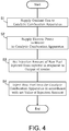
- FIG. 4 is a flowchart showing an example of processing procedures of the control method for the catalytic combustion apparatus 45 according to the present embodiment.
- the processing procedures of the control method are repeatedly executed at a predetermined cycle, for example, several hundred millisecond.
- step S1 the controller 50 supplies the oxidant gas to the catalytic combustion apparatus 45
- the controller 50 drives the compressor 22 to activate the catalytic combustion apparatus 45.
- the air containing the oxidant gas is supplied to the catalytic combustion apparatus 45 via the fuel cell 10
- step S2 the controller 50 supplies electric power to the heater 452 in the catalytic combustion apparatus 45.
- the controller 50 determines whether or not the detected value of the temperature sensor 53 falls below a predetermined combustion threshold, the detected value of the temperature sensor 53 served as the temperature of the catalyst 451 in the catalytic combustion apparatus 45.
- the controller 50 energizes the heater 452 by the electric power supply (not shown).
- the above combustion threshold is set based on the temperature at which the raw fuel gas can be combusted in the catalyst 451.
- the combustion threshold value of the present embodiment is set to a lower limit value of a temperature which allows the combustion reaction of the catalyst 451.
- step S3 the controller 50 sets the injection amount of the raw fuel injected from the injector 34 in response to the output of the heater 452.
- the controller 50 changes the injection period of the injector 34 in response to the detected value of the sensor that for detecting the electric power supplied to the heater 452.
- the sensor for detecting the electric power supplied to the heater 452 at least one of a current sensor for detecting the current supplied to the heater 452 and a voltage sensor for detecting the voltage supplied to the heater 452 is employed.
- the controller 50 shorten the injection period of the injector 42 as the electric power supplied to the heater 452 increases so that the injection amount of the raw fuel by the injector 42 does not exceed the upper limit line 453.
- the injection amount of the injector 34 can be increased within the temperature of the catalyst 451 not being dropped due to the latent heat of vaporization of the raw fuel in the reformer 39.
- step S4 the controller 50 injects the raw fuel into the catalytic combustion apparatus 45 in accordance with the injection amount which is set in step S3.
- the controller 50 injects the raw fuel from the injector 42 into the catalytic combustion apparatus 45 with the injection period corresponding to the electric power supplied to the heater 452.
- step S4 When the processing of step S4 is completed, a series of the processing procedures of the control method for the catalytic combustion apparatus 45 is completed.
- the catalytic combustion apparatus 45 includes the catalyst 451 for combusting the raw fuel, and the heater 452 capable of heating the raw fuel supplied to the catalyst 451.
- the catalytic combustion system 101 for operating the catalytic combustion apparatus 45 includes the compressor 22 as an actuator for supplying the oxidant gas to the catalytic combustion apparatus 45, and the injector 42 as an injector for injecting the raw fuel into the catalytic combustion apparatus 45.
- the catalytic combustion system 101 further includes the controller 50 configured to control the injection amount of the raw fuel to be injected into the catalytic combustion apparatus 45 in response to of the heater 452.
- the controller 50 is configured to execute the process of step S1 of supplying the oxidant gas to the catalytic combustion apparatus 45, and execute the injection step of injecting the raw fuel from the injector 42 to the catalytic combustion apparatus 45.
- the controller 50 is configured to execute the process of step S2 for supplying electric power to the heater 452, and execute the process of step S3 for setting the injection amount of the injector 42 in response to output of the heater 452.
- the controller 50 is configured to inject liquid fuel containing water as the raw fuel from the injector 34.
- the raw fuel is not vaporized and then stays at the bottom in the catalytic combustion apparatus 45 if the latent heat of vaporization of the raw fuel leads to the drop in the temperature of the catalytic combustion apparatus 45.
- the staying raw fuel then immerses the catalyst 451, the portion thereof comes to involve an excessively high concentration and thereby becomes deteriorated.
- the controller 50 of the present embodiment is configured to limit the injection amount of the injector 34 in response to output of the heater 452, it is possible to suppress the temperature drop in the catalytic combustion apparatus 45. Therefore, the raw fuel hardly stays in the bottom portion of the catalytic combustion apparatus 45. As a result, when activating the catalytic combustion apparatus 45, it is possible to promptly produce the fuel gas at the catalyst 451 as well as suppress deterioration of the catalyst 451.
- Fig. 5 is a flowchart illustrating an example of processing procedures of a method for starting-up the fuel cell system 100 in the present embodiment.
- the processing procedures of the control method are repeatedly executed at a predetermined cycle, for example, several hundred millisecond.
- step S11 the controller 50 receives an start-up command of the fuel cell system 100.
- the start-up command of the fuel cell system 100 is issued in response to such as a user's button operation or an electric power requirement from the load of the fuel cell 10.
- step S12 the controller 50 supplies the air to the catalytic combustion apparatus 45 via the fuel cell 10 by driving the compressor 22.
- step S13 the controller 50 energizes the heater 452 in the catalytic combustion apparatus 45.
- the controller 50 sets output of the heater 452 to an upper limit value in order to start the catalytic combustion apparatus 45.
- step S14 the controller 50 detects the temperature of the catalyst 451 in the catalytic combustion apparatus 45 by the temperature sensor 51.
- the temperature sensor 51 a temperature sensor 52 or a temperature sensor 53 may be employed.
- step S15 the controller 50 determines whether or not the temperature of the catalyst 451 is equal to or higher than the combustion threshold Th.
- the combustion threshold Th is set to the lower limit value of the temperature which allows the combustion reaction of the catalyst 451.
- the controller 50 waits until the temperature of the catalyst 451 reaches the combustion threshold Th.
- step S16 when the temperature of the catalyst 451 has risen up to the combustion threshold Th, the controller 50 sets the injection amount of the injector 42 to a predetermined value, and injects the raw fuel to the catalytic combustion apparatus 45 from the injector 42 in accordance with the set value.
- the above-described predetermined value is the injection amount of the raw fuel when the latent heat of vaporization of the raw fuel injected to the catalytic combustion apparatus 45 is equal to or less than output of the heater 452.
- the controller 50 sets the upper limit value of the injection amount corresponding to the upper limit value of output of the heater 452 as the injection amount of the injector 42, in accordance with the upper limit line 453 shown in FIG. 3 .
- step S17 the controller 50 determines whether or not the temperature of the catalyst 451 has risen under electric power being supplied to the heater 452. For example, the controller 50 determines that the temperature of the catalyst 451 has risen when a current value exceeds a previous value. The current value as well as the previous value is with respect to the temperature of the catalyst 451 or with respect to a moving average value thereof. Alternatively, the controller 50 may determine that the temperature of the catalyst 451 has risen when a temperature difference between the temperature of the catalyst 451 at the timing of the injector 42 having started the injection and the current temperature of the catalyst 451 exceeds a predetermined threshold value. When the controller 50 has determined that the temperature of the catalyst 451 has not increased, the controller 50 returns to the process of step S15.
- step S18 the controller 50 increases the injection amount of the injector 42 in accordance with a combustion energy generated by the combustion of the raw fuel in the catalytic combustion apparatus 45. Specifically, the controller 50 increases the injection amount of the injector 42 so that the latent heat of vaporization of the increment in the injection amount of the raw fuel is equal to or less than the combustion energy of the raw fuel before the increase.
- step S19 the controller 50 determines whether or not the temperature of the catalyst 451 has dropped. For example, with respect to the temperature of the catalyst 451 or the moving average value thereof, when the current value falls below the previous value, the controller 50 determines that the temperature of the catalyst 451 has dropped. Alternatively, when the temperature of the catalyst 451 after increase falls below the temperature of the catalyst 451 before increased, the controller 50 may determine that the temperature of the catalyst 451 has dropped.
- step S20 the controller 50 decreases the injection amount of the injector 42 so that the temperature of the catalyst 451 rises. For example, the controller 50 returns the injection amount of the injector 42 to the value set in step S16. Then, the controller 50 returns to the process of step S17.
- step S19 the controller 50 executes a warm-up process for raising the temperature of the fuel cell 10 to the temperature allowing the fuel cell 10 to generate electric power.
- the controller 50 terminates the starting-up method.
- the controller 50 executes the process of step S16 for limiting the injection amount of the injector 42 so that the latent heat of vaporization of the raw fuel in the catalytic combustion apparatus 45 becomes equal to or less than output of the heater 452.
- the controller 50 executes the process of step S18 for increasing the injection amount of the injector 42.
- step S18 it is possible to increase the injection amount of the injector 42 while suppressing the temperature drop in the catalytic combustion apparatus 45.
- the controller 50 increases the injection amount of the injector 42 so that the latent heat of vaporization of the increment in the injection amount of the raw fuel is equal to or less than the combustion energy of the raw fuel before the increase. As a result, it is possible to prevent the temperature of the catalytic combustion apparatus 45 from decreasing while increasing the injection amount of the injector 42.
- the controller 50 executes the process of step S20 for decreasing the injection amount of the injector 42 when the temperature of the catalyst 451 drops after the injection amount increased.
- step S20 for decreasing the injection amount of the injector 42 when the temperature of the catalyst 451 drops after the injection amount increased.
- the evaporator 35 is provided in the fuel cell system 100 in the above embodiment, the evaporator 35 may be omitted and replaced by the heater 36.
Landscapes
- Engineering & Computer Science (AREA)
- Chemical & Material Sciences (AREA)
- Combustion & Propulsion (AREA)
- Mechanical Engineering (AREA)
- General Engineering & Computer Science (AREA)
- Chemical Kinetics & Catalysis (AREA)
- Life Sciences & Earth Sciences (AREA)
- Manufacturing & Machinery (AREA)
- Sustainable Development (AREA)
- Sustainable Energy (AREA)
- Electrochemistry (AREA)
- General Chemical & Material Sciences (AREA)
- Fuel Cell (AREA)
- Feeding And Controlling Fuel (AREA)
Abstract
Description
- The present invention relates to a method for controlling a catalytic combustion apparatus having a heater and a catalytic combustion system.
-
JP2013-253004A - The above-described technique can be applied to a catalytic combustor. There, however, is a problem that the fuel is injected after the temperature of the catalyst being fully raised and thereby results in elongating a required time to activate the apparatus.
- The present invention has been made in view of the problem and an object of the present invention is to provide a control method and a catalytic combustion system for activating a catalytic combustion apparatus at an early stage.
- According to one aspect of the present invention, a method for controlling a catalytic combustion apparatus having a heater capable of heating fuel to be supplied to a catalyst includes a step of supplying oxidant gas to the catalytic combustion apparatus, and an injection step of injecting the fuel into the catalytic combustion apparatus. The injection step then includes an electric power feeding step of supplying electric power to the heater, and a setting step of setting an injection amount of the fuel to be injected into the catalytic combustion apparatus in response to output of the heater.
-
-
FIG. 1 is a diagram for showing a configuration example of a fuel cell system according to a first embodiment of the present invention. -
FIG. 2 is a diagram for showing a configuration example of a catalytic combustion apparatus provided in the fuel cell system. -
FIG. 3 is a diagram for explaining an area in which an injection amount of an injector is limited in accordance with output of the heater constituting the catalytic combustion apparatus. -
FIG. 4 is a flowchart for showing a control method of a catalytic combustion system in which the catalytic combustion apparatus according to the present embodiment is operated. -
FIG. 5 is a flowchart for showing a control method of the fuel cell system to which the catalytic combustion system is applied. - Embodiments of the present invention will be described below with reference to the accompanying drawings.
-
FIG. 1 is a configuration diagram showing an example of a configuration of afuel cell system 100 according to an embodiment of the present invention. - The
fuel cell system 100 allows afuel cell 10 to generate electric power by supplying fuel gas and oxidant gas to thefuel cell 10. Thefuel cell system 100 is mounted on a mobile body such as a vehicle, an airplane, or a ship. According to this present embodiment, thefuel cell system 100 is mounted on a vehicle such as a hybrid vehicle or an electric vehicle. - The
fuel cell system 100 includes thefuel cell 10, anoxidant supply device 20, afuel supply device 30, aheating device 40, and acontroller 50. - The
fuel cell 10 generates electric power, being supplied with fuel gas and the oxidant gas. Thefuel cell 10 is realized by a fuel cell such as a solid oxide type or a solid polymer type. Thefuel cell 10 of the present embodiment is laminated cells in which a plurality of a single solid oxide type fuel cell is stacked. For example, thefuel cell 10 generates electric power by a chemical reaction between the fuel gas and the oxidant gas under a temperature of thefuel cell 10 arriving at a range of 600° C. to 700° C. - The
oxidant supply device 20 supplies the oxidant gas to thefuel cell 10, the oxidant gas required for electric power generation of thefuel cell 10. Theoxidant supply device 20 includes anoxidant supply passage 21, acompressor 22, and anoxidant heat exchanger 23. - The
oxidant supply passage 21 is a passage for supplying the oxidant gas to thefuel cell 10. In the present embodiment, one end of theoxidant supply passage 21 communicates with the outside air, and the other end thereof is connected to an oxidant inlet hole of thefuel cell 10. - The
compressor 22 is an actuator provided in theoxidant supply passage 21. Thecompressor 22 sucks the air as the oxidant gas from the one end of theoxidant supply passage 21. Thecompressor 22 compresses the air and then supplies the air to thefuel cell 10 through theoxidant supply passage 21. Thecompressor 22 is used as the actuator in the present embodiment. Instead of thecompressor 22, a blower or the like may be used. - The
oxidant heat exchanger 23 is a heat exchanger that heats the oxidant gas to be supplied to thefuel cell 10, the heating of the oxidant gas is for warming up thefuel cell 10. In the present embodiment, theoxidant heat exchanger 23 performs heat exchange between the high-temperature exhaust gas generated by theheating device 40 and the air from thecompressor 22. Theoxidant heat exchanger 23 outputs the air to thefuel cell 10, the air having been heated by the heat exchange. - The
fuel supply device 30 supplies the fuel gas to thefuel cell 10, the fuel gas required for electric power generation of thefuel cell 10. Thefuel supply device 30 includes afuel supply passage 31, araw fuel tank 32, a fuel pump 33, aninjector 34, anevaporator 35, aheater 36, and areformer 37. - The
fuel supply passage 31 is a passage for supplying the fuel gas to thefuel cell 10. In the present embodiment, one end of thefuel supply passage 31 is connected to theraw fuel tank 32, the other end thereof is connected to a fuel inlet hole of thefuel cell 10. - The
raw fuel tank 32 stores raw fuel required for production of the fuel gas. As the raw fuel, an aqueous solution, which contains an oxygen-containing fuel and water, is employed. The oxygen-containing fuel is the raw fuel which contains an oxygen-containing compound such as alcohol or methyl tertiary butyl ether (MTBE). An ethanol aqueous solution is employed as the raw fuel of the present embodiment. The ethanol aqueous solution contains an approximately 40%vol of ethanol. - The fuel pump 33 supplies the raw fuel to the
injector 34, the raw fuel stored in theraw fuel tank 32. In the present embodiment, the fuel pump 33 is provided inside theraw fuel tank 32. Alternatively, the fuel pump 33 may be disposed between theraw fuel tank 32 and theinjector 34. - The
injector 34 is an injector for injecting the raw fuel. Theinjector 34 injects the raw fuel supplied by the fuel pump 33 into the evaporator 25 at predetermined cycles. - The
evaporator 35 vaporizes the raw fuel injected by theinjector 34 and results in generating mixed gas of water vapor and oxygenated fuel gas. Theevaporator 35 is heated, for example, by utilizing of the exhaust gas of theheating device 40. - The
heater 38 is a heat exchanger for raising the temperature of the mixed gas from theevaporator 35 up to a predetermined temperature required for reforming the mixed gas. The heater 26 of the present embodiment heats the mixed gas from the evaporator 25 by utilizing of the exhaust gas from theheating device 40. - The
reformer 39 reforms the mixed gas from theheater 36 and results in generating the fuel gas. Thereformer 39 then outputs the generated fuel gas to thefuel cell 10. - The
heating device 40 heats thefuel cell 10, theoxidant heat exchanger 23, theevaporator 35, theheater 38, and thereformer 39. Oxidant gas and fuel gas to thefuel cell 10 are thus heated. The raw fuel, which is injected from theinjector 34 to thereformer 39, is also heated. - The
heating device 40 includes araw fuel passage 41, aninjector 42, a fuelcell exhaust passage 43, a fuelcell exhaust passage 44, acatalytic combustion apparatus 45, and anexhaust passage 46. - The
raw fuel passage 41 is a passage for supplying the raw fuel to thecatalytic combustion apparatus 45. According to the present embodiment, one end of theraw fuel passage 41 is connected to a passage branching from thefuel supply passage 31 at upstream of theinjector 34. The other end of theraw fuel passage 41 is connected to theinjector 42. - The
injector 42 has the same configuration as theinjector 34 and also injects the raw fuel into thecatalytic combustion apparatus 45, the raw fuel being supplied by the fuel pump 33. - The fuel
cell exhaust passages catalytic combustion apparatus 45, the oxidant gas and the fuel gas discharged from thefuel cell 10. In the present embodiment, and one end of the fuelcell exhaust passage 43 is connected to an oxidant discharge hole of thefuel cell 10, and the other end thereof is connected to thecatalytic combustion apparatus 45. One end of the fuelcell exhaust passage 44 is connected to a fuel discharge hole of thefuel cell 10, and the other end thereof is connected to thecombustor 45. - The
catalytic combustion apparatus 45 serves as an exhaust combustor for combusting the mixed gas of the oxidant gas and the fuel gas discharged from thefuel cell 10. Thecatalytic combustion apparatus 45 also serves as a start-up combustor for combusting the raw fuel injected from theinjector 42 in order to allow thefuel cell system 100 to start. Thecatalytic combustion apparatus 45 outputs combustion gas to theexhaust passage 46 as exhaust gas, the combustion gas obtained by combusting fuel gas from thefuel cell 10 and the raw fuel from theinjector 42. - The
exhaust passage 46 is a passage for discharging the exhaust gas from thecatalytic combustion apparatus 45 to outside of thefuel cell system 100. Theexhaust passage 46 communicates with the outside, with having gone through from thecatalytic combustion apparatus 45 to theoxidant heat exchanger 23. Theexhaust passage 46 may branch from the middle of the path from thecatalytic combustion apparatus 45 to theoxidant heat exchanger 23 and communicate with the outside through thereformer 37, theheater 36, and theevaporator 35 in this order. - The
controller 50 is a controller for controlling an operation of thefuel cell system 100, and executing preprogrammed processing. Thecontroller 50 is configured by one or more microcomputers, which include a central processing unit (CPU) and a storage device. - Detection values of various sensors such as temperature sensors 51-53 are input to the
controller 50. For example, thetemperature sensor 51 is disposed in the fuelcell exhaust passage 44 to detect a temperature of an anode pole of thefuel cell 10. Thetemperature sensor 52 is disposed in theexhaust passage 46 to detect a temperature of the exhaust gas. - The
temperature sensor 53 detects a temperature of thecatalytic combustion apparatus 45. Since detection values of thetemperature sensors catalytic combustion apparatus 45, at least one of the detection values of thetemperature sensors catalytic combustion apparatus 45 instead of the detection value of thetemperature sensor 53. - The
controller 50 stores a program for executing a predetermined process. When thecontroller 50 receives a start-up operation by the user for thefuel cell system 100, an electric power request from a load of thefuel cell 10, or the like, thecontroller 50 executes a start-up process of thefuel cell system 100, the start-up process executed in order to allow thefuel cell 10 to become a state capable of generating electric power. - Specifically, the
controller 50 operates thecompressor 22 and theinjector 42 to activate thecatalytic combustion apparatus 45. The oxidant gas from thecompressor 22 is thus supplied to thecatalytic combustion apparatus 45 via thefuel cell 10, and the raw fuel is also injected from theinjector 42 to thecatalytic combustion apparatus 45. As a result, the raw fuel gas is combusted in thecatalytic combustion apparatus 45. - Since the
catalytic combustion apparatus 45 per se generates heat due to the combustion of the raw fuel gas, theheater 36 and thereformer 37 are heated. Theoxidant heat exchanger 23, theevaporator 35, theheater 36, thereformer 37, and the like are also heated by the exhaust gas from thecatalytic combustion apparatus 45. A startup process of thefuel cell system 100 completes when the temperature of thefuel cell 10 rises up to a temperature, which allows thefuel cell 10 to generate electric power. - Upon the completion of the startup process of the
fuel cell system 100, thecontroller 50 controls the operation of thecompressor 22 and theinjector 34 so that each of supply flow rates of the fuel gas and the oxidant gas to thefuel cell 10 becomes a predetermined target value. For example, the predetermined target value is set according to a magnitude of the load of thefuel cell 10. -
FIG. 2 is a diagram showing a basic configuration of acatalytic combustion system 101 for starting thecatalytic combustion apparatus 45 according to the present embodiment. Thecatalytic combustion system 101 is a part of thefuel cell system 100. - The
catalytic combustion apparatus 45 includes acatalyst 451 for burning the raw fuel and aheater 452 for heating the raw fuel to be supplied to thecatalyst 451. - The
catalyst 451 is a combustion catalyst which burns the raw fuel gas which has been vaporized by using the oxidant gas. Thecatalyst 451 and theheater 452 are arranged side by side so that an upstream end face of thecatalyst 451 and a downstream end face of theheater 452 are in contact with each other. Thecatalyst 451 is a member in which a catalyst material is supported on a surface of a honeycomb structure, the honeycomb structure serving as a support body. The honeycomb structure is formed as a cylindrical member made of metal. Platinum (Pt), palladium (Pd), or the like can be employed as the catalyst material, which is supported on the honeycomb structure. - The
heater 452 is an electric heater that vaporizes the raw fuel injected into thecatalyst 451, and is used, for example in a situation where the temperature of thecatalyst 451 is lower than the temperature at which the raw fuel can be combusted. Therefore, theheater 452 is not used in a self-sustaining operation state in which a main body temperature of a main body of thecatalytic combustion apparatus 45 is sufficiently high. - The
heater 452 is composed of the honeycomb structure served as a body, and an electrode portion provided on an outer periphery of the honeycomb structure. The honeycomb structure is formed as a cylindrical member made of metal, and is fixed in thecatalytic combustion apparatus 45. Theelectrode portion 452A is provided so as to protrude from inside of thecatalytic combustion apparatus 45 toward the outside. The honeycomb structure is heated by electrically energizing theelectrode portion 452A. - The
controller 50 is configured to supply electric power to theheater 452 by energizing theheater 452 from an electric power source when activating thecatalytic combustion apparatus 45, the electric power source such as a battery not shown in drawings. - When electric power is supplied to the
heater 452, that is, under theheater 452 heating thecatalyst 451, the injection of theinjector 42 generally has been stopped until the temperature of thecatalyst 451 reaches an operating temperature. The operating temperature is a temperature at which the injection amount of the raw fuel under the self-sustaining operation can be sufficiently combusted. Under such a waiting time being provided, a required time up to the combustion of the raw fuel from a start of the energization of theheater 452, i.e., the time required for starting thecatalytic combustion apparatus 45 elongates. - On the other hand, when the raw fuel is injected from the
injector 34 to thecatalytic combustion apparatus 45 under thecatalyst 451 heated by theheater 452, the combustion reaction may not occur because latent heat of vaporization of the raw fuel leads to a drop in the temperature of thecatalyst 451. In such a situation, when liquid raw fuel stays at the bottom of thecatalytic combustion apparatus 45 and the staying raw fuel comes into contact with thecatalyst 451, a concentration of the raw fuel becomes excessively high in the portion. Thecatalyst 451 thus deteriorates. - The
controller 50 of the present embodiment is configured to limit the injection amount of the raw fuel from theinjector 34 to thecatalytic combustion apparatus 45 in order to activate thecatalytic combustion apparatus 45, in response to output of theheater 452 under electric power being supplied to theheater 452. -
Figure 3 is a diagram for explaining a relationship between the output of theheater 452 and the injection amount of theinjector 34. - The output of the
heater 452 is a value obtained by converting an amount of heat radiated from theheater 452 into electric power [W], which is approximately equivalent to the electric power supplied to theheater 452. - The injection amount of the
injector 42 is adjusted by an injection period [millisecond] of theinjector 42. In the present embodiment, the injection amount per one injection by theinjector 42 is fixed. Thus, the shorter the injection period [millisecond] is, the more the injection amount from theinjector 42 is increased. - An
upper limit line 453 is defined so as to avoid a drop in the temperature of thecatalyst 451. Theupper limit line 453 indicates an upper limit value for the injection amount of the raw fuel which theinjector 42 can inject according to the output of theheater 452. Theupper limit line 453 is set so that thermal energy, which is the output of theheater 452, exceeds the latent heat of vaporization (energy) of the raw fuel injected from theinjector 42. - The
controller 50 of the present embodiment is configured to hold a map shown in the relationship shown inFIG. 3 . When electric power is supplied to theheater 452, thecontroller 50 is configured to increase the injection amount of theinjector 42 referring to the above map, as the output of theheater 452 becomes larger within the injected amount of theinjector 42 not exceeding theupper limit line 453. - In this manner, when electric power is supplied to the
heater 452, thecontroller 50 limits the injection amount of the raw fuel so that the latent heat of vaporization of the raw fuel in thecatalytic combustion apparatus 45 becomes equal to or less than the output of theheater 452. -
FIG. 4 is a flowchart showing an example of processing procedures of the control method for thecatalytic combustion apparatus 45 according to the present embodiment. The processing procedures of the control method are repeatedly executed at a predetermined cycle, for example, several hundred millisecond. - In step S1, the
controller 50 supplies the oxidant gas to thecatalytic combustion apparatus 45 In this embodiment, thecontroller 50 drives thecompressor 22 to activate thecatalytic combustion apparatus 45. Thus, the air containing the oxidant gas is supplied to thecatalytic combustion apparatus 45 via thefuel cell 10 - In step S2, the
controller 50 supplies electric power to theheater 452 in thecatalytic combustion apparatus 45. In the present embodiment, thecontroller 50 determines whether or not the detected value of thetemperature sensor 53 falls below a predetermined combustion threshold, the detected value of thetemperature sensor 53 served as the temperature of thecatalyst 451 in thecatalytic combustion apparatus 45. When the temperature of thecatalyst 451 falls below the combustion threshold, thecontroller 50 energizes theheater 452 by the electric power supply (not shown). - The above combustion threshold is set based on the temperature at which the raw fuel gas can be combusted in the
catalyst 451. The combustion threshold value of the present embodiment is set to a lower limit value of a temperature which allows the combustion reaction of thecatalyst 451. - In step S3, the
controller 50 sets the injection amount of the raw fuel injected from theinjector 34 in response to the output of theheater 452. In the present embodiment, thecontroller 50 changes the injection period of theinjector 34 in response to the detected value of the sensor that for detecting the electric power supplied to theheater 452. - As the sensor for detecting the electric power supplied to the
heater 452, at least one of a current sensor for detecting the current supplied to theheater 452 and a voltage sensor for detecting the voltage supplied to theheater 452 is employed. - For example, as shown in
FIG. 3 , thecontroller 50 shorten the injection period of theinjector 42 as the electric power supplied to theheater 452 increases so that the injection amount of the raw fuel by theinjector 42 does not exceed theupper limit line 453. Thus, as the electric power supplied to theheater 452 increases, the injection amount of theinjector 34 can be increased within the temperature of thecatalyst 451 not being dropped due to the latent heat of vaporization of the raw fuel in thereformer 39. - In step S4, the
controller 50 injects the raw fuel into thecatalytic combustion apparatus 45 in accordance with the injection amount which is set in step S3. In the present embodiment, thecontroller 50 injects the raw fuel from theinjector 42 into thecatalytic combustion apparatus 45 with the injection period corresponding to the electric power supplied to theheater 452. - When the processing of step S4 is completed, a series of the processing procedures of the control method for the
catalytic combustion apparatus 45 is completed. - According to the first embodiment of the present invention, as shown in
FIG. 2 , thecatalytic combustion apparatus 45 includes thecatalyst 451 for combusting the raw fuel, and theheater 452 capable of heating the raw fuel supplied to thecatalyst 451. Thecatalytic combustion system 101 for operating thecatalytic combustion apparatus 45 includes thecompressor 22 as an actuator for supplying the oxidant gas to thecatalytic combustion apparatus 45, and theinjector 42 as an injector for injecting the raw fuel into thecatalytic combustion apparatus 45. Thecatalytic combustion system 101 further includes thecontroller 50 configured to control the injection amount of the raw fuel to be injected into thecatalytic combustion apparatus 45 in response to of theheater 452. - Then, in the control method of the
catalytic combustion apparatus 45, as shown inFIG. 4 , thecontroller 50 is configured to execute the process of step S1 of supplying the oxidant gas to thecatalytic combustion apparatus 45, and execute the injection step of injecting the raw fuel from theinjector 42 to thecatalytic combustion apparatus 45. In the injection step, thecontroller 50 is configured to execute the process of step S2 for supplying electric power to theheater 452, and execute the process of step S3 for setting the injection amount of theinjector 42 in response to output of theheater 452. - Thus, when electric power is supplied to the
heater 452, for example in a scene that thecatalytic combustion apparatus 45 is activated, it is possible to limit the injection amount of theinjector 34 in response to output of theheater 452. As a result, it is possible to suppress a drop in the temperature of thecatalytic combustion apparatus 45. Therefore, since it is not necessary to wait for the injection of the raw fuel until the temperature of thecatalytic combustion apparatus 45 reaches the operating temperature suitable for the combustion reaction in thecatalyst 451, it is possible to activate thecatalytic combustion apparatus 45 early. - According to the present embodiment, the
controller 50 is configured to inject liquid fuel containing water as the raw fuel from theinjector 34. In such a scene that the liquid fuel is employed as the raw fuel, the raw fuel is not vaporized and then stays at the bottom in thecatalytic combustion apparatus 45 if the latent heat of vaporization of the raw fuel leads to the drop in the temperature of thecatalytic combustion apparatus 45. When the staying raw fuel then immerses thecatalyst 451, the portion thereof comes to involve an excessively high concentration and thereby becomes deteriorated. - On the other hand, since the
controller 50 of the present embodiment is configured to limit the injection amount of theinjector 34 in response to output of theheater 452, it is possible to suppress the temperature drop in thecatalytic combustion apparatus 45. Therefore, the raw fuel hardly stays in the bottom portion of thecatalytic combustion apparatus 45. As a result, when activating thecatalytic combustion apparatus 45, it is possible to promptly produce the fuel gas at thecatalyst 451 as well as suppress deterioration of thecatalyst 451. - Next, operation of the
catalytic combustion apparatus 45 applied to thefuel cell system 100 as the second embodiment of the present invention will be described. -
Fig. 5 is a flowchart illustrating an example of processing procedures of a method for starting-up thefuel cell system 100 in the present embodiment. The processing procedures of the control method are repeatedly executed at a predetermined cycle, for example, several hundred millisecond. - In step S11, the
controller 50 receives an start-up command of thefuel cell system 100. The start-up command of thefuel cell system 100 is issued in response to such as a user's button operation or an electric power requirement from the load of thefuel cell 10. - In step S12, the
controller 50 supplies the air to thecatalytic combustion apparatus 45 via thefuel cell 10 by driving thecompressor 22. - In step S13, the
controller 50 energizes theheater 452 in thecatalytic combustion apparatus 45. In the present embodiment, thecontroller 50 sets output of theheater 452 to an upper limit value in order to start thecatalytic combustion apparatus 45. - In step S14, the
controller 50 detects the temperature of thecatalyst 451 in thecatalytic combustion apparatus 45 by thetemperature sensor 51. Instead of thetemperature sensor 51, atemperature sensor 52 or atemperature sensor 53 may be employed. - In step S15, the
controller 50 determines whether or not the temperature of thecatalyst 451 is equal to or higher than the combustion threshold Th. In the present embodiment, the combustion threshold Th is set to the lower limit value of the temperature which allows the combustion reaction of thecatalyst 451. When the temperature of thecatalyst 451 is lower than the combustion threshold Th, thecontroller 50 waits until the temperature of thecatalyst 451 reaches the combustion threshold Th. - In step S16, when the temperature of the
catalyst 451 has risen up to the combustion threshold Th, thecontroller 50 sets the injection amount of theinjector 42 to a predetermined value, and injects the raw fuel to thecatalytic combustion apparatus 45 from theinjector 42 in accordance with the set value. - The above-described predetermined value is the injection amount of the raw fuel when the latent heat of vaporization of the raw fuel injected to the
catalytic combustion apparatus 45 is equal to or less than output of theheater 452. In the present embodiment, thecontroller 50 sets the upper limit value of the injection amount corresponding to the upper limit value of output of theheater 452 as the injection amount of theinjector 42, in accordance with theupper limit line 453 shown inFIG. 3 . - In step S17, the
controller 50 determines whether or not the temperature of thecatalyst 451 has risen under electric power being supplied to theheater 452. For example, thecontroller 50 determines that the temperature of thecatalyst 451 has risen when a current value exceeds a previous value. The current value as well as the previous value is with respect to the temperature of thecatalyst 451 or with respect to a moving average value thereof. Alternatively, thecontroller 50 may determine that the temperature of thecatalyst 451 has risen when a temperature difference between the temperature of thecatalyst 451 at the timing of theinjector 42 having started the injection and the current temperature of thecatalyst 451 exceeds a predetermined threshold value. When thecontroller 50 has determined that the temperature of thecatalyst 451 has not increased, thecontroller 50 returns to the process of step S15. - When the
controller 50 has determined that the temperature of thecatalyst 451 has risen, in step S18, thecontroller 50 increases the injection amount of theinjector 42 in accordance with a combustion energy generated by the combustion of the raw fuel in thecatalytic combustion apparatus 45. Specifically, thecontroller 50 increases the injection amount of theinjector 42 so that the latent heat of vaporization of the increment in the injection amount of the raw fuel is equal to or less than the combustion energy of the raw fuel before the increase. - In step S19, the
controller 50 determines whether or not the temperature of thecatalyst 451 has dropped. For example, with respect to the temperature of thecatalyst 451 or the moving average value thereof, when the current value falls below the previous value, thecontroller 50 determines that the temperature of thecatalyst 451 has dropped. Alternatively, when the temperature of thecatalyst 451 after increase falls below the temperature of thecatalyst 451 before increased, thecontroller 50 may determine that the temperature of thecatalyst 451 has dropped. - When the
controller 50 has determined that the temperature of thecatalyst 451 has dropped, in step S20, thecontroller 50 decreases the injection amount of theinjector 42 so that the temperature of thecatalyst 451 rises. For example, thecontroller 50 returns the injection amount of theinjector 42 to the value set in step S16. Then, thecontroller 50 returns to the process of step S17. - When the
controller 50 has determined that the temperature of thecatalyst 451 has not dropped in step S19, thecontroller 50 executes a warm-up process for raising the temperature of thefuel cell 10 to the temperature allowing thefuel cell 10 to generate electric power. When the warm-up process is completed, thecontroller 50 terminates the starting-up method. - According to the second embodiment of the present invention, when the temperature of the
catalytic combustion apparatus 45 exceeds the predetermined threshold value, thecontroller 50 executes the process of step S16 for limiting the injection amount of theinjector 42 so that the latent heat of vaporization of the raw fuel in thecatalytic combustion apparatus 45 becomes equal to or less than output of theheater 452. - As a result, it is possible to prevent the raw fuel from being injected into the
catalytic combustion apparatus 45 before the temperature of thecatalyst 451 rises up to the temperature which allows the raw fuel gas to be combusted by thecatalyst 451. Therefore, it is possible to suppress the raw fuel from staying at the bottom of thecatalytic combustion apparatus 45, and to suppress deterioration of thecatalyst 451. - According to the present embodiment, when the temperature of the
catalytic combustion apparatus 45 rises after starting of the injection of the raw fuel under electric power being supplied to theheater 452, thecontroller 50 executes the process of step S18 for increasing the injection amount of theinjector 42. As a result, it is possible to increase the injection amount of theinjector 42 while suppressing the temperature drop in thecatalytic combustion apparatus 45. - Further, according to the present embodiment, the
controller 50 increases the injection amount of theinjector 42 so that the latent heat of vaporization of the increment in the injection amount of the raw fuel is equal to or less than the combustion energy of the raw fuel before the increase. As a result, it is possible to prevent the temperature of thecatalytic combustion apparatus 45 from decreasing while increasing the injection amount of theinjector 42. - According to the present embodiment, the
controller 50 executes the process of step S20 for decreasing the injection amount of theinjector 42 when the temperature of thecatalyst 451 drops after the injection amount increased. Thus, it is possible to promptly suppress the temperature drop in thecatalytic combustion apparatus 45 and also to avoid the deterioration of thecatalyst 451. - While embodiments of the present invention have been described above, the above-described embodiments only show a part of the application example of the present invention, and the technical scope of the present invention is not intended to limit to the specific configurations of the above-described embodiments.
- For example, although the
evaporator 35 is provided in thefuel cell system 100 in the above embodiment, theevaporator 35 may be omitted and replaced by theheater 36. - The above-described embodiments can be combined as appropriate.
Claims (7)
- A method for controlling a catalytic combustion apparatus having a heater capable of heating fuel to be supplied to a catalyst, comprising:a step of supplying oxidant gas to the catalytic combustion apparatus; andan injection step of injecting the fuel into the catalytic combustion apparatus,wherein the injection step comprises:an electric power feeding step of supplying electric power to the heater, anda setting step of setting an injection amount of the fuel to be injected into the catalytic combustion apparatus in response to output of the heater.
- A method for controlling the catalytic combustion apparatus according to claim 1, wherein
the injection step comprises injecting liquid fuel as the fuel, the liquid fuel containing water. - A method for controlling the catalytic combustion apparatus according to claim 1 or 2, wherein
the setting step comprises limiting the injection amount when a temperature of the catalytic combustion apparatus exceeds a predetermined threshold, the injection amount limited so that a latent heat of vaporization of the fuel supplied to the catalytic combustion apparatus is equal to or less than the output of the heater. - A method for controlling the catalytic combustion apparatus according to claim 3, wherein
the setting step comprises increasing the injection amount when the temperature of the catalytic combustion apparatus rises after start of the injection of the fuel under electric power being supplied to the heater. - A method for controlling the catalytic combustion apparatus according to claim 4, wherein
the injection step comprises increasing the injection amount so that the latent heat of vaporization in an increment in the injection amount of the fuel is less than a combustion energy of the fuel. - A method for controlling the catalytic combustion apparatus according to claim 4 or 5, wherein
the setting step comprises decreasing the injection amount when the temperature drops under the injection amount having been increased. - A catalytic combustion system comprising:a catalytic combustion apparatus having a heater capable of heating fuel supplied to a catalyst;an actuator supplying oxidant gas to the catalytic combustion apparatus;an injector injecting the fuel into the catalytic combustion apparatus; anda controller configured to control an injection amount of the fuel to be injected into the catalytic combustion apparatus in response to output of the heater.
Applications Claiming Priority (1)
| Application Number | Priority Date | Filing Date | Title |
|---|---|---|---|
| PCT/JP2018/021265 WO2019229994A1 (en) | 2018-06-01 | 2018-06-01 | Method for controlling catalyst combustion device, and catalyst combustion system |
Publications (3)
| Publication Number | Publication Date |
|---|---|
| EP3806212A1 true EP3806212A1 (en) | 2021-04-14 |
| EP3806212A4 EP3806212A4 (en) | 2021-06-09 |
| EP3806212B1 EP3806212B1 (en) | 2024-04-17 |
Family
ID=68697941
Family Applications (1)
| Application Number | Title | Priority Date | Filing Date |
|---|---|---|---|
| EP18920491.0A Active EP3806212B1 (en) | 2018-06-01 | 2018-06-01 | Method for controlling a catalytic combustion apparatus, and catalytic combustion system |
Country Status (5)
| Country | Link |
|---|---|
| US (1) | US11898750B2 (en) |
| EP (1) | EP3806212B1 (en) |
| JP (1) | JP7111158B2 (en) |
| CN (1) | CN112136238B (en) |
| WO (1) | WO2019229994A1 (en) |
Family Cites Families (24)
| Publication number | Priority date | Publication date | Assignee | Title |
|---|---|---|---|---|
| JPS5245739A (en) * | 1975-10-09 | 1977-04-11 | Toshiba Electric Appliance Co Ltd | Pot type combustion device |
| JPS60233414A (en) * | 1984-05-07 | 1985-11-20 | Matsushita Electric Ind Co Ltd | Catalyst combustion device |
| JPH0526130A (en) * | 1991-07-19 | 1993-02-02 | Ngk Spark Plug Co Ltd | Fuel supply device with heater |
| JP3657675B2 (en) * | 1994-12-06 | 2005-06-08 | 松下電器産業株式会社 | Combustion equipment |
| DE69528513T2 (en) | 1994-12-06 | 2003-02-13 | Matsushita Electric Industrial Co., Ltd. | combustion device |
| JPH1122916A (en) * | 1997-07-04 | 1999-01-26 | Matsushita Electric Ind Co Ltd | Combustion equipment |
| JP2000191304A (en) * | 1998-12-25 | 2000-07-11 | Ishikawajima Harima Heavy Ind Co Ltd | Liquid fuel evaporator and fuel cell reformer using the same |
| JP3578002B2 (en) * | 1999-07-09 | 2004-10-20 | 日産自動車株式会社 | Fuel cell system combustor |
| JP3582062B2 (en) * | 2000-07-06 | 2004-10-27 | 本田技研工業株式会社 | Fuel evaporator warm-up device |
| JP3398862B2 (en) * | 2000-07-06 | 2003-04-21 | 本田技研工業株式会社 | How to warm up the fuel evaporator |
| JP3480451B2 (en) * | 2001-05-22 | 2003-12-22 | 日産自動車株式会社 | Fuel cell system |
| JP2003193936A (en) * | 2001-12-25 | 2003-07-09 | Toyota Motor Corp | Fuel injection valve |
| US6913004B2 (en) * | 2002-03-22 | 2005-07-05 | Chrysalis Technologies Incorporated | Fuel system for an internal combustion engine and method for controlling same |
| JP4346575B2 (en) * | 2005-03-30 | 2009-10-21 | 株式会社東芝 | Fuel reformer and fuel cell system |
| JP5203652B2 (en) * | 2007-08-02 | 2013-06-05 | 本田技研工業株式会社 | Catalytic combustion device |
| JP5325403B2 (en) * | 2007-08-29 | 2013-10-23 | Jx日鉱日石エネルギー株式会社 | Starting method of fuel cell system |
| JP2009162162A (en) * | 2008-01-08 | 2009-07-23 | Honda Motor Co Ltd | Exhaust gas purification device for internal combustion engine |
| JP5619024B2 (en) * | 2008-12-26 | 2014-11-05 | ジーエイチティー・グローバル・ヒーティング・テクノロジーズ・ゲーエムベーハー | Jet cavity catalyst heating device |
| SE536578C2 (en) * | 2012-05-15 | 2014-03-04 | Reformtech Heating Holding Ab | Fuel injection system for use in a catalytic heater and reactor for conducting catalytic combustion liquid fuels |
| JP5806979B2 (en) * | 2012-06-08 | 2015-11-10 | 株式会社豊田自動織機 | Reformer |
| CN103887545B (en) * | 2012-12-21 | 2016-04-27 | 中国科学院大连化学物理研究所 | A kind of high-temp liquid fuel cell start-up method |
| WO2015141752A1 (en) * | 2014-03-18 | 2015-09-24 | 京セラ株式会社 | Fuel battery device |
| JP6529391B2 (en) * | 2015-08-31 | 2019-06-12 | 日立造船株式会社 | Heating device and fuel cell system |
| JP6759573B2 (en) * | 2015-12-15 | 2020-09-23 | 日産自動車株式会社 | Fuel cell system control method and fuel cell system |
-
2018
- 2018-06-01 EP EP18920491.0A patent/EP3806212B1/en active Active
- 2018-06-01 CN CN201880093560.2A patent/CN112136238B/en active Active
- 2018-06-01 JP JP2020522553A patent/JP7111158B2/en active Active
- 2018-06-01 WO PCT/JP2018/021265 patent/WO2019229994A1/en not_active Ceased
- 2018-06-01 US US17/059,652 patent/US11898750B2/en active Active
Also Published As
| Publication number | Publication date |
|---|---|
| US20210262662A1 (en) | 2021-08-26 |
| CN112136238B (en) | 2024-02-27 |
| JPWO2019229994A1 (en) | 2021-06-17 |
| JP7111158B2 (en) | 2022-08-02 |
| WO2019229994A1 (en) | 2019-12-05 |
| EP3806212A4 (en) | 2021-06-09 |
| EP3806212B1 (en) | 2024-04-17 |
| US11898750B2 (en) | 2024-02-13 |
| CN112136238A (en) | 2020-12-25 |
Similar Documents
| Publication | Publication Date | Title |
|---|---|---|
| EP3392950B1 (en) | Fuel cell system and control method for fuel cell system | |
| JP6627888B2 (en) | Solid oxide fuel cell system and method of controlling solid oxide fuel cell system | |
| CN108432016B (en) | Fuel cell system and control method thereof | |
| JP2001229953A (en) | Fuel cell system | |
| EP3392948A1 (en) | Fuel cell system and control method for fuel cell system | |
| US11898750B2 (en) | Control method for a catalytic combustion apparatus and a catalytic combustion system | |
| JP7344723B2 (en) | fuel cell system | |
| EP3664207A1 (en) | Fuel cell system and control system for same | |
| JP5203652B2 (en) | Catalytic combustion device | |
| JP6996154B2 (en) | Fuel supply device | |
| CN110959213B (en) | Fuel cell system and control method of fuel cell system | |
| JP7848285B1 (en) | Fuel cell system | |
| JP6939282B2 (en) | Fuel cell system and start control method | |
| CN113169363B (en) | Combustion system and combustion system control method | |
| JP7353158B2 (en) | fuel cell system | |
| EP3664208B1 (en) | Fuel cell system control method and fuel cell system | |
| JP6981089B2 (en) | Fuel cell system and control method of fuel cell system | |
| WO2021116725A1 (en) | Method for controlling fuel cell system and fuel cell system | |
| JPWO2019229877A1 (en) | Fuel cell system and how to operate it | |
| TW200826349A (en) | Fuel cell system with lower initiation current |
Legal Events
| Date | Code | Title | Description |
|---|---|---|---|
| STAA | Information on the status of an ep patent application or granted ep patent |
Free format text: STATUS: THE INTERNATIONAL PUBLICATION HAS BEEN MADE |
|
| PUAI | Public reference made under article 153(3) epc to a published international application that has entered the european phase |
Free format text: ORIGINAL CODE: 0009012 |
|
| STAA | Information on the status of an ep patent application or granted ep patent |
Free format text: STATUS: REQUEST FOR EXAMINATION WAS MADE |
|
| 17P | Request for examination filed |
Effective date: 20201216 |
|
| AK | Designated contracting states |
Kind code of ref document: A1 Designated state(s): AL AT BE BG CH CY CZ DE DK EE ES FI FR GB GR HR HU IE IS IT LI LT LU LV MC MK MT NL NO PL PT RO RS SE SI SK SM TR |
|
| AX | Request for extension of the european patent |
Extension state: BA ME |
|
| A4 | Supplementary search report drawn up and despatched |
Effective date: 20210507 |
|
| RIC1 | Information provided on ipc code assigned before grant |
Ipc: H01M 8/06 20160101AFI20210430BHEP Ipc: H01M 8/04 20160101ALI20210430BHEP Ipc: F23D 11/26 20060101ALI20210430BHEP Ipc: F23D 11/44 20060101ALI20210430BHEP Ipc: F23N 1/00 20060101ALI20210430BHEP Ipc: H01M 8/04701 20160101ALI20210430BHEP |
|
| DAV | Request for validation of the european patent (deleted) | ||
| DAX | Request for extension of the european patent (deleted) | ||
| STAA | Information on the status of an ep patent application or granted ep patent |
Free format text: STATUS: EXAMINATION IS IN PROGRESS |
|
| 17Q | First examination report despatched |
Effective date: 20220706 |
|
| REG | Reference to a national code |
Ref country code: DE Ref legal event code: R079 Free format text: PREVIOUS MAIN CLASS: H01M0008060000 Ipc: H01M0008040000 Ref country code: DE Ref legal event code: R079 Ref document number: 602018068390 Country of ref document: DE Free format text: PREVIOUS MAIN CLASS: H01M0008060000 Ipc: H01M0008040000 |
|
| GRAP | Despatch of communication of intention to grant a patent |
Free format text: ORIGINAL CODE: EPIDOSNIGR1 |
|
| STAA | Information on the status of an ep patent application or granted ep patent |
Free format text: STATUS: GRANT OF PATENT IS INTENDED |
|
| RIC1 | Information provided on ipc code assigned before grant |
Ipc: F23D 11/26 20060101ALI20231030BHEP Ipc: F23D 11/44 20060101ALI20231030BHEP Ipc: F23N 1/00 20060101ALI20231030BHEP Ipc: H01M 8/06 20160101ALI20231030BHEP Ipc: H01M 8/04 20160101AFI20231030BHEP |
|
| INTG | Intention to grant announced |
Effective date: 20231114 |
|
| GRAJ | Information related to disapproval of communication of intention to grant by the applicant or resumption of examination proceedings by the epo deleted |
Free format text: ORIGINAL CODE: EPIDOSDIGR1 |
|
| STAA | Information on the status of an ep patent application or granted ep patent |
Free format text: STATUS: EXAMINATION IS IN PROGRESS |
|
| GRAP | Despatch of communication of intention to grant a patent |
Free format text: ORIGINAL CODE: EPIDOSNIGR1 |
|
| STAA | Information on the status of an ep patent application or granted ep patent |
Free format text: STATUS: GRANT OF PATENT IS INTENDED |
|
| INTC | Intention to grant announced (deleted) | ||
| INTG | Intention to grant announced |
Effective date: 20240205 |
|
| GRAS | Grant fee paid |
Free format text: ORIGINAL CODE: EPIDOSNIGR3 |
|
| GRAA | (expected) grant |
Free format text: ORIGINAL CODE: 0009210 |
|
| STAA | Information on the status of an ep patent application or granted ep patent |
Free format text: STATUS: THE PATENT HAS BEEN GRANTED |
|
| AK | Designated contracting states |
Kind code of ref document: B1 Designated state(s): AL AT BE BG CH CY CZ DE DK EE ES FI FR GB GR HR HU IE IS IT LI LT LU LV MC MK MT NL NO PL PT RO RS SE SI SK SM TR |
|
| REG | Reference to a national code |
Ref country code: GB Ref legal event code: FG4D |
|
| REG | Reference to a national code |
Ref country code: CH Ref legal event code: EP |
|
| REG | Reference to a national code |
Ref country code: DE Ref legal event code: R096 Ref document number: 602018068390 Country of ref document: DE |
|
| REG | Reference to a national code |
Ref country code: IE Ref legal event code: FG4D |
|
| REG | Reference to a national code |
Ref country code: LT Ref legal event code: MG9D |
|
| REG | Reference to a national code |
Ref country code: NL Ref legal event code: MP Effective date: 20240417 |
|
| REG | Reference to a national code |
Ref country code: AT Ref legal event code: MK05 Ref document number: 1678148 Country of ref document: AT Kind code of ref document: T Effective date: 20240417 |
|
| PG25 | Lapsed in a contracting state [announced via postgrant information from national office to epo] |
Ref country code: NL Free format text: LAPSE BECAUSE OF FAILURE TO SUBMIT A TRANSLATION OF THE DESCRIPTION OR TO PAY THE FEE WITHIN THE PRESCRIBED TIME-LIMIT Effective date: 20240417 |
|
| PG25 | Lapsed in a contracting state [announced via postgrant information from national office to epo] |
Ref country code: NL Free format text: LAPSE BECAUSE OF FAILURE TO SUBMIT A TRANSLATION OF THE DESCRIPTION OR TO PAY THE FEE WITHIN THE PRESCRIBED TIME-LIMIT Effective date: 20240417 |
|
| PG25 | Lapsed in a contracting state [announced via postgrant information from national office to epo] |
Ref country code: IS Free format text: LAPSE BECAUSE OF FAILURE TO SUBMIT A TRANSLATION OF THE DESCRIPTION OR TO PAY THE FEE WITHIN THE PRESCRIBED TIME-LIMIT Effective date: 20240817 |
|
| PG25 | Lapsed in a contracting state [announced via postgrant information from national office to epo] |
Ref country code: BG Free format text: LAPSE BECAUSE OF FAILURE TO SUBMIT A TRANSLATION OF THE DESCRIPTION OR TO PAY THE FEE WITHIN THE PRESCRIBED TIME-LIMIT Effective date: 20240417 |
|
| PG25 | Lapsed in a contracting state [announced via postgrant information from national office to epo] |
Ref country code: HR Free format text: LAPSE BECAUSE OF FAILURE TO SUBMIT A TRANSLATION OF THE DESCRIPTION OR TO PAY THE FEE WITHIN THE PRESCRIBED TIME-LIMIT Effective date: 20240417 Ref country code: FI Free format text: LAPSE BECAUSE OF FAILURE TO SUBMIT A TRANSLATION OF THE DESCRIPTION OR TO PAY THE FEE WITHIN THE PRESCRIBED TIME-LIMIT Effective date: 20240417 |
|
| PG25 | Lapsed in a contracting state [announced via postgrant information from national office to epo] |
Ref country code: GR Free format text: LAPSE BECAUSE OF FAILURE TO SUBMIT A TRANSLATION OF THE DESCRIPTION OR TO PAY THE FEE WITHIN THE PRESCRIBED TIME-LIMIT Effective date: 20240718 |
|
| PG25 | Lapsed in a contracting state [announced via postgrant information from national office to epo] |
Ref country code: PT Free format text: LAPSE BECAUSE OF FAILURE TO SUBMIT A TRANSLATION OF THE DESCRIPTION OR TO PAY THE FEE WITHIN THE PRESCRIBED TIME-LIMIT Effective date: 20240819 |
|
| PG25 | Lapsed in a contracting state [announced via postgrant information from national office to epo] |
Ref country code: ES Free format text: LAPSE BECAUSE OF FAILURE TO SUBMIT A TRANSLATION OF THE DESCRIPTION OR TO PAY THE FEE WITHIN THE PRESCRIBED TIME-LIMIT Effective date: 20240417 |
|
| PG25 | Lapsed in a contracting state [announced via postgrant information from national office to epo] |
Ref country code: AT Free format text: LAPSE BECAUSE OF FAILURE TO SUBMIT A TRANSLATION OF THE DESCRIPTION OR TO PAY THE FEE WITHIN THE PRESCRIBED TIME-LIMIT Effective date: 20240417 |
|
| PG25 | Lapsed in a contracting state [announced via postgrant information from national office to epo] |
Ref country code: PL Free format text: LAPSE BECAUSE OF FAILURE TO SUBMIT A TRANSLATION OF THE DESCRIPTION OR TO PAY THE FEE WITHIN THE PRESCRIBED TIME-LIMIT Effective date: 20240417 |
|
| PG25 | Lapsed in a contracting state [announced via postgrant information from national office to epo] |
Ref country code: LV Free format text: LAPSE BECAUSE OF FAILURE TO SUBMIT A TRANSLATION OF THE DESCRIPTION OR TO PAY THE FEE WITHIN THE PRESCRIBED TIME-LIMIT Effective date: 20240417 |
|
| PG25 | Lapsed in a contracting state [announced via postgrant information from national office to epo] |
Ref country code: PT Free format text: LAPSE BECAUSE OF FAILURE TO SUBMIT A TRANSLATION OF THE DESCRIPTION OR TO PAY THE FEE WITHIN THE PRESCRIBED TIME-LIMIT Effective date: 20240819 Ref country code: PL Free format text: LAPSE BECAUSE OF FAILURE TO SUBMIT A TRANSLATION OF THE DESCRIPTION OR TO PAY THE FEE WITHIN THE PRESCRIBED TIME-LIMIT Effective date: 20240417 Ref country code: NO Free format text: LAPSE BECAUSE OF FAILURE TO SUBMIT A TRANSLATION OF THE DESCRIPTION OR TO PAY THE FEE WITHIN THE PRESCRIBED TIME-LIMIT Effective date: 20240717 Ref country code: LV Free format text: LAPSE BECAUSE OF FAILURE TO SUBMIT A TRANSLATION OF THE DESCRIPTION OR TO PAY THE FEE WITHIN THE PRESCRIBED TIME-LIMIT Effective date: 20240417 Ref country code: IS Free format text: LAPSE BECAUSE OF FAILURE TO SUBMIT A TRANSLATION OF THE DESCRIPTION OR TO PAY THE FEE WITHIN THE PRESCRIBED TIME-LIMIT Effective date: 20240817 Ref country code: HR Free format text: LAPSE BECAUSE OF FAILURE TO SUBMIT A TRANSLATION OF THE DESCRIPTION OR TO PAY THE FEE WITHIN THE PRESCRIBED TIME-LIMIT Effective date: 20240417 Ref country code: GR Free format text: LAPSE BECAUSE OF FAILURE TO SUBMIT A TRANSLATION OF THE DESCRIPTION OR TO PAY THE FEE WITHIN THE PRESCRIBED TIME-LIMIT Effective date: 20240718 Ref country code: FI Free format text: LAPSE BECAUSE OF FAILURE TO SUBMIT A TRANSLATION OF THE DESCRIPTION OR TO PAY THE FEE WITHIN THE PRESCRIBED TIME-LIMIT Effective date: 20240417 Ref country code: ES Free format text: LAPSE BECAUSE OF FAILURE TO SUBMIT A TRANSLATION OF THE DESCRIPTION OR TO PAY THE FEE WITHIN THE PRESCRIBED TIME-LIMIT Effective date: 20240417 Ref country code: BG Free format text: LAPSE BECAUSE OF FAILURE TO SUBMIT A TRANSLATION OF THE DESCRIPTION OR TO PAY THE FEE WITHIN THE PRESCRIBED TIME-LIMIT Effective date: 20240417 Ref country code: AT Free format text: LAPSE BECAUSE OF FAILURE TO SUBMIT A TRANSLATION OF THE DESCRIPTION OR TO PAY THE FEE WITHIN THE PRESCRIBED TIME-LIMIT Effective date: 20240417 Ref country code: RS Free format text: LAPSE BECAUSE OF FAILURE TO SUBMIT A TRANSLATION OF THE DESCRIPTION OR TO PAY THE FEE WITHIN THE PRESCRIBED TIME-LIMIT Effective date: 20240717 |
|
| PG25 | Lapsed in a contracting state [announced via postgrant information from national office to epo] |
Ref country code: DK Free format text: LAPSE BECAUSE OF FAILURE TO SUBMIT A TRANSLATION OF THE DESCRIPTION OR TO PAY THE FEE WITHIN THE PRESCRIBED TIME-LIMIT Effective date: 20240417 |
|
| REG | Reference to a national code |
Ref country code: DE Ref legal event code: R097 Ref document number: 602018068390 Country of ref document: DE |
|
| PG25 | Lapsed in a contracting state [announced via postgrant information from national office to epo] |
Ref country code: EE Free format text: LAPSE BECAUSE OF FAILURE TO SUBMIT A TRANSLATION OF THE DESCRIPTION OR TO PAY THE FEE WITHIN THE PRESCRIBED TIME-LIMIT Effective date: 20240417 |
|
| PG25 | Lapsed in a contracting state [announced via postgrant information from national office to epo] |
Ref country code: CZ Free format text: LAPSE BECAUSE OF FAILURE TO SUBMIT A TRANSLATION OF THE DESCRIPTION OR TO PAY THE FEE WITHIN THE PRESCRIBED TIME-LIMIT Effective date: 20240417 |
|
| PG25 | Lapsed in a contracting state [announced via postgrant information from national office to epo] |
Ref country code: SK Free format text: LAPSE BECAUSE OF FAILURE TO SUBMIT A TRANSLATION OF THE DESCRIPTION OR TO PAY THE FEE WITHIN THE PRESCRIBED TIME-LIMIT Effective date: 20240417 Ref country code: RO Free format text: LAPSE BECAUSE OF FAILURE TO SUBMIT A TRANSLATION OF THE DESCRIPTION OR TO PAY THE FEE WITHIN THE PRESCRIBED TIME-LIMIT Effective date: 20240417 |
|
| PG25 | Lapsed in a contracting state [announced via postgrant information from national office to epo] |
Ref country code: SM Free format text: LAPSE BECAUSE OF FAILURE TO SUBMIT A TRANSLATION OF THE DESCRIPTION OR TO PAY THE FEE WITHIN THE PRESCRIBED TIME-LIMIT Effective date: 20240417 |
|
| PG25 | Lapsed in a contracting state [announced via postgrant information from national office to epo] |
Ref country code: SM Free format text: LAPSE BECAUSE OF FAILURE TO SUBMIT A TRANSLATION OF THE DESCRIPTION OR TO PAY THE FEE WITHIN THE PRESCRIBED TIME-LIMIT Effective date: 20240417 Ref country code: SK Free format text: LAPSE BECAUSE OF FAILURE TO SUBMIT A TRANSLATION OF THE DESCRIPTION OR TO PAY THE FEE WITHIN THE PRESCRIBED TIME-LIMIT Effective date: 20240417 Ref country code: RO Free format text: LAPSE BECAUSE OF FAILURE TO SUBMIT A TRANSLATION OF THE DESCRIPTION OR TO PAY THE FEE WITHIN THE PRESCRIBED TIME-LIMIT Effective date: 20240417 Ref country code: EE Free format text: LAPSE BECAUSE OF FAILURE TO SUBMIT A TRANSLATION OF THE DESCRIPTION OR TO PAY THE FEE WITHIN THE PRESCRIBED TIME-LIMIT Effective date: 20240417 Ref country code: DK Free format text: LAPSE BECAUSE OF FAILURE TO SUBMIT A TRANSLATION OF THE DESCRIPTION OR TO PAY THE FEE WITHIN THE PRESCRIBED TIME-LIMIT Effective date: 20240417 Ref country code: CZ Free format text: LAPSE BECAUSE OF FAILURE TO SUBMIT A TRANSLATION OF THE DESCRIPTION OR TO PAY THE FEE WITHIN THE PRESCRIBED TIME-LIMIT Effective date: 20240417 Ref country code: MC Free format text: LAPSE BECAUSE OF FAILURE TO SUBMIT A TRANSLATION OF THE DESCRIPTION OR TO PAY THE FEE WITHIN THE PRESCRIBED TIME-LIMIT Effective date: 20240417 |
|
| REG | Reference to a national code |
Ref country code: CH Ref legal event code: PL |
|
| PG25 | Lapsed in a contracting state [announced via postgrant information from national office to epo] |
Ref country code: IT Free format text: LAPSE BECAUSE OF FAILURE TO SUBMIT A TRANSLATION OF THE DESCRIPTION OR TO PAY THE FEE WITHIN THE PRESCRIBED TIME-LIMIT Effective date: 20240417 |
|
| PG25 | Lapsed in a contracting state [announced via postgrant information from national office to epo] |
Ref country code: LU Free format text: LAPSE BECAUSE OF NON-PAYMENT OF DUE FEES Effective date: 20240601 |
|
| PLBE | No opposition filed within time limit |
Free format text: ORIGINAL CODE: 0009261 |
|
| STAA | Information on the status of an ep patent application or granted ep patent |
Free format text: STATUS: NO OPPOSITION FILED WITHIN TIME LIMIT |
|
| 26N | No opposition filed |
Effective date: 20250120 |
|
| PG25 | Lapsed in a contracting state [announced via postgrant information from national office to epo] |
Ref country code: IE Free format text: LAPSE BECAUSE OF NON-PAYMENT OF DUE FEES Effective date: 20240601 |
|
| PG25 | Lapsed in a contracting state [announced via postgrant information from national office to epo] |
Ref country code: SI Free format text: LAPSE BECAUSE OF FAILURE TO SUBMIT A TRANSLATION OF THE DESCRIPTION OR TO PAY THE FEE WITHIN THE PRESCRIBED TIME-LIMIT Effective date: 20240417 Ref country code: BE Free format text: LAPSE BECAUSE OF NON-PAYMENT OF DUE FEES Effective date: 20240630 Ref country code: CH Free format text: LAPSE BECAUSE OF NON-PAYMENT OF DUE FEES Effective date: 20240630 |
|
| REG | Reference to a national code |
Ref country code: BE Ref legal event code: MM Effective date: 20240630 |
|
| PGFP | Annual fee paid to national office [announced via postgrant information from national office to epo] |
Ref country code: DE Payment date: 20250520 Year of fee payment: 8 |
|
| PGFP | Annual fee paid to national office [announced via postgrant information from national office to epo] |
Ref country code: GB Payment date: 20250520 Year of fee payment: 8 |
|
| PGFP | Annual fee paid to national office [announced via postgrant information from national office to epo] |
Ref country code: FR Payment date: 20250520 Year of fee payment: 8 |
|
| PG25 | Lapsed in a contracting state [announced via postgrant information from national office to epo] |
Ref country code: SE Free format text: LAPSE BECAUSE OF FAILURE TO SUBMIT A TRANSLATION OF THE DESCRIPTION OR TO PAY THE FEE WITHIN THE PRESCRIBED TIME-LIMIT Effective date: 20240417 |
|
| PG25 | Lapsed in a contracting state [announced via postgrant information from national office to epo] |
Ref country code: CY Free format text: LAPSE BECAUSE OF FAILURE TO SUBMIT A TRANSLATION OF THE DESCRIPTION OR TO PAY THE FEE WITHIN THE PRESCRIBED TIME-LIMIT; INVALID AB INITIO Effective date: 20180601 |
|
| PG25 | Lapsed in a contracting state [announced via postgrant information from national office to epo] |
Ref country code: HU Free format text: LAPSE BECAUSE OF FAILURE TO SUBMIT A TRANSLATION OF THE DESCRIPTION OR TO PAY THE FEE WITHIN THE PRESCRIBED TIME-LIMIT; INVALID AB INITIO Effective date: 20180601 |