EP3806177A1 - Cover assembly of secondary battery and secondary battery - Google Patents
Cover assembly of secondary battery and secondary battery Download PDFInfo
- Publication number
- EP3806177A1 EP3806177A1 EP20827974.5A EP20827974A EP3806177A1 EP 3806177 A1 EP3806177 A1 EP 3806177A1 EP 20827974 A EP20827974 A EP 20827974A EP 3806177 A1 EP3806177 A1 EP 3806177A1
- Authority
- EP
- European Patent Office
- Prior art keywords
- air hole
- blocker
- secondary battery
- fastener
- cover plate
- Prior art date
- Legal status (The legal status is an assumption and is not a legal conclusion. Google has not performed a legal analysis and makes no representation as to the accuracy of the status listed.)
- Granted
Links
Images


Classifications
-
- H—ELECTRICITY
- H01—ELECTRIC ELEMENTS
- H01M—PROCESSES OR MEANS, e.g. BATTERIES, FOR THE DIRECT CONVERSION OF CHEMICAL ENERGY INTO ELECTRICAL ENERGY
- H01M50/00—Constructional details or processes of manufacture of the non-active parts of electrochemical cells other than fuel cells, e.g. hybrid cells
- H01M50/10—Primary casings; Jackets or wrappings
- H01M50/147—Lids or covers
- H01M50/148—Lids or covers characterised by their shape
-
- H—ELECTRICITY
- H01—ELECTRIC ELEMENTS
- H01M—PROCESSES OR MEANS, e.g. BATTERIES, FOR THE DIRECT CONVERSION OF CHEMICAL ENERGY INTO ELECTRICAL ENERGY
- H01M50/00—Constructional details or processes of manufacture of the non-active parts of electrochemical cells other than fuel cells, e.g. hybrid cells
- H01M50/30—Arrangements for facilitating escape of gases
- H01M50/342—Non-re-sealable arrangements
-
- H—ELECTRICITY
- H01—ELECTRIC ELEMENTS
- H01M—PROCESSES OR MEANS, e.g. BATTERIES, FOR THE DIRECT CONVERSION OF CHEMICAL ENERGY INTO ELECTRICAL ENERGY
- H01M50/00—Constructional details or processes of manufacture of the non-active parts of electrochemical cells other than fuel cells, e.g. hybrid cells
- H01M50/10—Primary casings; Jackets or wrappings
- H01M50/183—Sealing members
- H01M50/184—Sealing members characterised by their shape or structure
-
- H—ELECTRICITY
- H01—ELECTRIC ELEMENTS
- H01M—PROCESSES OR MEANS, e.g. BATTERIES, FOR THE DIRECT CONVERSION OF CHEMICAL ENERGY INTO ELECTRICAL ENERGY
- H01M50/00—Constructional details or processes of manufacture of the non-active parts of electrochemical cells other than fuel cells, e.g. hybrid cells
- H01M50/10—Primary casings; Jackets or wrappings
- H01M50/183—Sealing members
- H01M50/186—Sealing members characterised by the disposition of the sealing members
-
- H—ELECTRICITY
- H01—ELECTRIC ELEMENTS
- H01M—PROCESSES OR MEANS, e.g. BATTERIES, FOR THE DIRECT CONVERSION OF CHEMICAL ENERGY INTO ELECTRICAL ENERGY
- H01M50/00—Constructional details or processes of manufacture of the non-active parts of electrochemical cells other than fuel cells, e.g. hybrid cells
- H01M50/10—Primary casings; Jackets or wrappings
- H01M50/183—Sealing members
- H01M50/19—Sealing members characterised by the material
- H01M50/193—Organic material
-
- H—ELECTRICITY
- H01—ELECTRIC ELEMENTS
- H01M—PROCESSES OR MEANS, e.g. BATTERIES, FOR THE DIRECT CONVERSION OF CHEMICAL ENERGY INTO ELECTRICAL ENERGY
- H01M50/00—Constructional details or processes of manufacture of the non-active parts of electrochemical cells other than fuel cells, e.g. hybrid cells
- H01M50/30—Arrangements for facilitating escape of gases
- H01M50/375—Vent means sensitive to or responsive to temperature
-
- H—ELECTRICITY
- H01—ELECTRIC ELEMENTS
- H01M—PROCESSES OR MEANS, e.g. BATTERIES, FOR THE DIRECT CONVERSION OF CHEMICAL ENERGY INTO ELECTRICAL ENERGY
- H01M2200/00—Safety devices for primary or secondary batteries
- H01M2200/10—Temperature sensitive devices
-
- H—ELECTRICITY
- H01—ELECTRIC ELEMENTS
- H01M—PROCESSES OR MEANS, e.g. BATTERIES, FOR THE DIRECT CONVERSION OF CHEMICAL ENERGY INTO ELECTRICAL ENERGY
- H01M2220/00—Batteries for particular applications
- H01M2220/10—Batteries in stationary systems, e.g. emergency power source in plant
-
- H—ELECTRICITY
- H01—ELECTRIC ELEMENTS
- H01M—PROCESSES OR MEANS, e.g. BATTERIES, FOR THE DIRECT CONVERSION OF CHEMICAL ENERGY INTO ELECTRICAL ENERGY
- H01M50/00—Constructional details or processes of manufacture of the non-active parts of electrochemical cells other than fuel cells, e.g. hybrid cells
- H01M50/10—Primary casings; Jackets or wrappings
- H01M50/147—Lids or covers
- H01M50/148—Lids or covers characterised by their shape
- H01M50/15—Lids or covers characterised by their shape for prismatic or rectangular cells
-
- H—ELECTRICITY
- H01—ELECTRIC ELEMENTS
- H01M—PROCESSES OR MEANS, e.g. BATTERIES, FOR THE DIRECT CONVERSION OF CHEMICAL ENERGY INTO ELECTRICAL ENERGY
- H01M50/00—Constructional details or processes of manufacture of the non-active parts of electrochemical cells other than fuel cells, e.g. hybrid cells
- H01M50/10—Primary casings; Jackets or wrappings
- H01M50/147—Lids or covers
- H01M50/155—Lids or covers characterised by the material
- H01M50/157—Inorganic material
- H01M50/159—Metals
-
- H—ELECTRICITY
- H01—ELECTRIC ELEMENTS
- H01M—PROCESSES OR MEANS, e.g. BATTERIES, FOR THE DIRECT CONVERSION OF CHEMICAL ENERGY INTO ELECTRICAL ENERGY
- H01M50/00—Constructional details or processes of manufacture of the non-active parts of electrochemical cells other than fuel cells, e.g. hybrid cells
- H01M50/30—Arrangements for facilitating escape of gases
- H01M50/308—Detachable arrangements, e.g. detachable vent plugs or plug systems
-
- H—ELECTRICITY
- H01—ELECTRIC ELEMENTS
- H01M—PROCESSES OR MEANS, e.g. BATTERIES, FOR THE DIRECT CONVERSION OF CHEMICAL ENERGY INTO ELECTRICAL ENERGY
- H01M50/00—Constructional details or processes of manufacture of the non-active parts of electrochemical cells other than fuel cells, e.g. hybrid cells
- H01M50/30—Arrangements for facilitating escape of gases
- H01M50/317—Re-sealable arrangements
- H01M50/325—Re-sealable arrangements comprising deformable valve members, e.g. elastic or flexible valve members
-
- Y—GENERAL TAGGING OF NEW TECHNOLOGICAL DEVELOPMENTS; GENERAL TAGGING OF CROSS-SECTIONAL TECHNOLOGIES SPANNING OVER SEVERAL SECTIONS OF THE IPC; TECHNICAL SUBJECTS COVERED BY FORMER USPC CROSS-REFERENCE ART COLLECTIONS [XRACs] AND DIGESTS
- Y02—TECHNOLOGIES OR APPLICATIONS FOR MITIGATION OR ADAPTATION AGAINST CLIMATE CHANGE
- Y02E—REDUCTION OF GREENHOUSE GAS [GHG] EMISSIONS, RELATED TO ENERGY GENERATION, TRANSMISSION OR DISTRIBUTION
- Y02E60/00—Enabling technologies; Technologies with a potential or indirect contribution to GHG emissions mitigation
- Y02E60/10—Energy storage using batteries
Definitions
- Embodiments of this application relate to the technical field of energy storage devices, and in particular, to a cover assembly of a secondary battery and a secondary battery.
- Safety performance is extremely important for a secondary battery that serves as an important component of a new energy vehicle.
- gas may be generated inside the secondary battery, and excessively high air pressure may cause an explosion of the secondary battery. Therefore, an explosion-proof valve based on air pressure control can be disposed on a cover plate of the secondary battery.
- a plurality of secondary batteries usually need to be arranged into a battery module for use because one secondary battery has a small capacity or power.
- This application provides a cover assembly of a secondary battery and a secondary battery from various aspects to resolve the problem in the prior art and improve safety performance of secondary batteries.
- a first aspect of this application provides a cover assembly of a secondary battery, including:
- a melting point of the fastener ranges from 80°C to 200°C
- the blocker is a metal block.
- the blocker includes a body and a connection portion
- the blocker further includes a limiting element
- both the connection portion and the limiting element have an annular structure; and an outer diameter of the limiting element is greater than an outer diameter of the connection portion.
- a projection of the limiting element along a thickness direction Z of the cover assembly is within a projection of the air hole along the thickness direction Z of the cover assembly.
- an annular sink is provided in the cover plate; the sink surrounds the air hole and extends along a radial direction of the air hole; and the body is accommodated in the sink.
- an annular groove is provided in the cover plate; the groove surrounds the air hole and recesses from a bottom surface of the sink towards a side facing away from the body; and at least a part of the sealing member is accommodated in the groove.
- the cover assembly further includes an insulation plate, and the insulation plate is disposed on an inner side of the cover plate; and the fastener and the insulation plate are integrally formed.
- a second aspect of this application provides a secondary battery, including:
- the blocker of the cover assembly of the secondary battery blocks the air hole, and the blocker is connected to the cover plate through the fastener.
- the fastener is configured to get deformed in response to the temperature rise, so that the blocker exits the state of blocking the air hole.
- the blocker no longer blocks the air hole as a temperature inside the housing of the secondary battery rises, so as to discharge gas from the housing through the air hole. In this way, the secondary battery can be prevented from an explosion because of reduced air pressure inside the housing, while partial heat can be taken away through gas discharge, thereby slowing down thermal runaway in the secondary battery and providing enough escaping time for passengers.
- the sealing member is disposed between the blocker and the cover plate, surrounding the air hole and configured to seal the gap between the blocker and the cover plate, thereby improving sealing performance of the blocker to protect the secondary battery in a normal working state from electrolyte leakage and prevent external water vapor from entering the housing, and further improving the safety performance and service life of the secondary battery.
- the blocker extends into and blocks the air hole, and the fastener is disposed inside the air hole; therefore, the blocker can securely block the air hole and is not prone to falling off in a case of no thermal runaway in the secondary battery. Moreover, no additional fastening object such as a press block is required to secure the blocker, reducing occupation space and improving energy density of the secondary battery.
- FIG. 1 is a schematic structural diagram of a secondary battery according to an embodiment of this application.
- FIG. 2 is a main cross-sectional view of a structure of a secondary battery according to an embodiment of this application. As shown in FIGs. 1 and 2 , the embodiments of this application provide a secondary battery 100, including a housing 2, an electrode assembly 3, and a cover assembly 1.
- the housing 2 may be of a hexahedron shape or another shape, and an accommodating cavity is formed inside the housing 2 to accommodate the electrode assembly 3 and an electrolyte. An opening is provided at one end of the housing 2, so that the electrode assembly 3 can be placed in the accommodating cavity of the housing 2 through the opening. A plurality of electrode assemblies 3 may be disposed in the accommodating cavity, and the plurality of electrode assemblies 3 are stacked.
- the housing 2 may be made of a metal material, such as aluminum or aluminum alloy, or may be made of an insulation material, such as plastic.
- the electrode assembly 3 includes an electrode unit and a tab.
- the electrode unit includes a negative electrode plate, a positive electrode plate, and a separator.
- the separator is located between the negative electrode plate and the positive electrode plate that are adjacent to each other, to separate the negative electrode plate from the positive electrode plate.
- the negative electrode plate, the separator, and the positive electrode plate are sequentially stacked and wound to form the electrode unit of the electrode assembly 3, that is, the electrode unit has a winding structure.
- the negative electrode plate, the separator, and the positive electrode plate are sequentially stacked to form the electrode unit of the electrode assembly 3, that is, the electrode unit has a stack structure. There is a gap in the formed electrode unit. The electrolyte is able to enter the electrode unit through the gap to immerse the negative electrode plate and the positive electrode plate.
- the negative electrode plate includes a negative electrode current collector (for example, copper foil) and a negative electrode active material layer (for example, carbon or silicon) coated on a surface of the negative electrode current collector.
- the positive electrode plate includes a positive electrode current collector (for example, aluminum foil) and a positive electrode active material layer (for example, a ternary material, lithium iron phosphate, or lithium cobalt oxide) coated on a surface of the positive electrode current collector.
- the negative tab is connected to the negative electrode plate and extends from the electrode unit. The negative tab may be directly cut from the negative electrode current collector.
- the positive tab is connected to the positive electrode plate and extends from the electrode unit. The positive tab may be directly cut from the positive electrode current collector.
- FIG. 3 is an exploded structural diagram of a cover assembly of a secondary battery according to an embodiment of this application.
- the cover assembly 1 includes a cover plate 11 and an electrode terminal 17.
- the cover plate 11 is secured to the opening of the housing 2, containing the electrode assembly 3 and the electrolyte inside the accommodating cavity of the housing 2.
- the electrode terminal 17 is disposed on the cover plate 11 and includes a negative electrode terminal 17 and a positive electrode terminal 17.
- the two electrode terminals 17 and corresponding tabs are electrically connected through an adapting sheet 4.
- An explosion-proof hole 111 is provided in the cover plate 11, and an explosion-proof sheet 12 covers the explosion-proof hole 111.
- the adapting sheet 4 is located between the electrode unit of the electrode assembly 3 and the cover plate 11.
- the adapting sheet 4 includes a negative adapting sheet 4 and a positive adapting sheet 4.
- the negative adapting sheet 4 is configured to connect the negative tab and the negative electrode terminal 17.
- the positive adapting sheet 4 is configured to connect the positive tab and the positive electrode terminal 17.
- a plurality of the secondary batteries 100 can form a battery module. If thermal runaway occurs in one secondary battery 100 of the battery module, heat is transferred to an adjacent secondary battery 100, causing thermal runaway in surrounding secondary batteries 100.
- FIG. 4 is a main view of a cover assembly of a secondary battery according to an embodiment of this application.
- FIG. 5 is a cross-sectional view of FIG. 4 in an A-A direction.
- FIG. 6 is an enlarged view of position B in FIG. 5 .
- the cover assembly 1 includes a cover plate 11, a blocker 13, a sealing member 14, and a fastener 15.
- the cover plate 11 has an air hole 112, and the blocker 13 extends into and blocks the air hole 112.
- the sealing member 14 is disposed between the blocker 13 and the cover plate 11, surrounding the air hole 112 and configured to seal a gap between the blocker 13 and the cover plate 11.
- the fastener 15 is disposed inside the air hole 112.
- the fastener 15 is connected to the cover plate 11, and the blocker 13 is connected to the cover plate 11 through the fastener 15.
- the fastener 15 is configured to get deformed in response to a temperature rise, so that the blocker 13 exits a state of blocking the air hole 112.
- the blocker 13 blocks the air hole 112, and the blocker 13 is connected to the cover plate 11 through the fastener 15.
- the fastener 15 is configured to get deformed in response to the temperature rise, so that the blocker 13 exits the state of blocking the air hole 112.
- the blocker 13 no longer blocks the air hole 112 as a temperature inside the housing 2 of the secondary battery 100 rises, so as to discharge gas from the housing 2 through the air hole 112.
- the secondary battery 100 can be prevented from an explosion because of reduced air pressure inside the housing 2, while partial heat can be taken away through gas discharge, thereby slowing down thermal runaway in the secondary battery 100 and providing enough escaping time for passengers.
- the sealing member 14 is disposed between the blocker 13 and the cover plate 11, surrounding the air hole 112 and configured to seal the gap between the blocker 13 and the cover plate 11, thereby improving sealing performance of the blocker 13 to protect the secondary battery 100 in a normal working state from electrolyte leakage and prevent external water vapor from entering the housing 2, and further improving the safety performance and service life of the secondary battery 100.
- the blocker 13 extends into and blocks the air hole 112, and the fastener 15 is disposed inside the air hole 112; therefore, the blocker 13 can securely block the air hole 112 and is not prone to falling off in a case of no thermal runaway in the secondary battery 100. Moreover, no additional fastening object such as a press block is required to secure the blocker 13, reducing occupation space and improving energy density of the secondary battery 100.
- the fastener 15 has a melting point lower than that of the cover plate 11.
- a material of the fastener 15 may be PP (polypropylene, polypropylene), PE (polyethylene, polyethylene), or the like.
- the fastener 15 is deformed, that is, getting melted or softened.
- the blocker 13 exits the state of blocking the air hole 112, so that the air hole 112 is opened to discharge the gas inside the housing 2 of the secondary battery 100 out of the housing 2 through the air hole 112.
- a melting point of the fastener 15 ranges from 80°C to 200°C
- the blocker 13 is a metal block.
- the blocker 13 of a metal material can prevent water vapor or other gas outside the housing 2 from penetrating into the housing 2, and also prevent the electrolyte inside the housing 2 of the secondary battery 100 from permeating out of the housing 2, thereby improving the service life of the secondary battery 100.
- the blocker 13 includes a body 131 and a connection portion 132.
- the body 131 is flat-plate shaped, and the body 131 completely covers the air hole 112 and is located on an outer side of the cover plate 11.
- One end of the connection portion 132 is connected to the body 131, and the other end of the connection portion 132 extends into the air hole 112 and is connected to the fastener 15.
- Completely covering the air hole 112 by the body 131 can further prevent water vapor or other gas outside the housing 2 from penetrating into the housing 2, and further prevent the electrolyte in the housing 2 of the secondary battery 100 from permeating out of the housing 2.
- the other end of the connection portion 132 extends into the air hole 112 and is connected to the fastener 15, so that the blocker 13 can be securely connected to the air hole 112, not requiring an additional fastening object. This reduces space of the secondary battery 100 and improves energy density of the secondary battery 100.
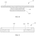
- FIG. 7 is a schematic diagram of fitting another type of blocker to a cover plate and a fastener.
- FIG. 8 is a main cross-sectional view of a structure of another type of blocker.
- the blocker 13 further includes a limiting element 133.
- the limiting element 133 is connected to an end of the connection portion 132 facing away from the body 131.
- a limiting step 151 is disposed on a side of the fastener 15 facing away from the body 131.
- the limiting element 133 abuts against the limiting step 151.
- the limiting element 133 may be formed by riveting. In a case of no thermal runaway in the secondary battery 100, disposition of the limiting element 133 can prevent the body 131 and the connection portion 132 from falling off the air hole 112.
- both the connection portion 132 and the limiting element 133 have an annular structure.
- An outer diameter of the limiting element 133 is greater than an outer diameter of the connection portion 132.
- the air hole 112 is a circular hole, and the connection portion 132 is fitted to the air hole 112.
- the limiting element 133 may be formed by riveting and abut against the limiting step 151. Because the outer diameter of the limiting element 133 is greater than the outer diameter of the connection portion 132, the body 131 and the connection portion 132 can be prevented from falling off the air hole 112 in a case of no thermal runaway in the secondary battery 100.
- a projection of the limiting element 133 along a thickness direction Z of the cover assembly 1 is within a projection of the air hole 112 along the thickness direction Z of the cover assembly 1.
- the outer diameter of the limiting element 133 is smaller than an aperture of the air hole 112. In this way, when the fastener 15 becomes deformed in response to a temperature rise, the blocker 13 is able to fall off the air hole 112, instead of interfering with the air hole 112 to affect gas discharge.
- FIG. 9 is a schematic diagram of a partial structure of the cover plate in FIG. 7 .
- an annular sink 114 is provided in the cover plate 11.
- the sink 114 surrounds the air hole 112 and extends along a radial direction of the air hole 112.
- the body 131 is accommodated in the sink 114.
- the annular sink 114 is provided on the cover plate 11, so that the body 131 is accommodated in the sink 114. In this way, the body 131 of the blocker 13 does not occupy excessive space outside the cover plate 11, conducive to weight reduction and miniaturization of the secondary battery 100.
- an annular groove 113 is provided in the cover plate 11.
- the groove 113 surrounds the air hole 112 and recesses from a bottom surface of the sink 114 towards a side facing away from the body 131. At least a part of the sealing member 14 is accommodated in the groove 113.
- the annular groove 113 is provided on the cover plate 11, so that at least a part of the sealing member 14 is accommodated in the groove 113. In this way, the sealing member 14 does not occupy excessive space outside the cover plate 11, conducive to weight reduction and miniaturization of the secondary battery 100. The sealing member 14 does not occupy space on a side, close to the electrode assembly 3, inside the cover plate 11, thereby improving the energy density of the secondary battery 100.
- the cover assembly 1 further includes an insulation plate 16.
- the insulation plate 16 is disposed on an inner side of the cover plate 11; and the fastener 15 and the insulation plate 16 are integrally formed.
- the insulation plate 16 can insulate and isolate the cover plate 11 from the electrode assembly 3 in the housing 2.
- the fastener 15 and the insulation plate 16 are integrally formed, simplifying a process. In one embodiment, the fastener 15 and the insulation plate 16 are integrally formed by using a same material. In another embodiment, the fastener 15 and the insulation plate 16 are integrally formed by using different materials.
Landscapes
- Chemical & Material Sciences (AREA)
- Chemical Kinetics & Catalysis (AREA)
- Electrochemistry (AREA)
- General Chemical & Material Sciences (AREA)
- Sealing Battery Cases Or Jackets (AREA)
Abstract
Description
- This application claims priority to Chinese Patent Application No.
201921326582.7 - Embodiments of this application relate to the technical field of energy storage devices, and in particular, to a cover assembly of a secondary battery and a secondary battery.
- Safety performance is extremely important for a secondary battery that serves as an important component of a new energy vehicle. During charging and discharging of the secondary battery, gas may be generated inside the secondary battery, and excessively high air pressure may cause an explosion of the secondary battery. Therefore, an explosion-proof valve based on air pressure control can be disposed on a cover plate of the secondary battery.
- A plurality of secondary batteries usually need to be arranged into a battery module for use because one secondary battery has a small capacity or power. Once thermal runaway occurs in one secondary battery of the battery module, generated heat is quickly transferred to other secondary batteries in the battery module to cause thermal runaway in the other secondary batteries, resulting in a sharp rise in temperature and air pressure. During thermal runaway, the existing explosion-proof valve based on air pressure control has a risk of failing to release the pressure in a timely manner and resulting in an explosion of the secondary battery.
- Therefore, it is necessary to design a new secondary battery to resolve the foregoing problem and improve safety performance of secondary batteries.
- This application provides a cover assembly of a secondary battery and a secondary battery from various aspects to resolve the problem in the prior art and improve safety performance of secondary batteries.
- A first aspect of this application provides a cover assembly of a secondary battery, including:
- a cover plate with an air hole;
- a blocker extending into and blocking the air hole;
- a sealing member disposed between the blocker and the cover plate, surrounding the air hole, and configured to seal a gap between the blocker and the cover plate; and
- a fastener disposed inside the air hole, where the fastener is connected to the cover plate, the blocker is connected to the cover plate through the fastener, and the fastener is configured to get deformed in response to a temperature rise, so that the blocker exits a state of blocking the air hole.
- In a possible design, a melting point of the fastener ranges from 80°C to 200°C, and the blocker is a metal block.
- In a possible design, the blocker includes a body and a connection portion;
- the body is flat-plate shaped, and the body completely covers the air hole and is located on an outer side of the cover plate; and
- one end of the connection portion is connected to the body, and the other end of the connection portion extends into the air hole and is connected to the fastener.
- In a possible design, the blocker further includes a limiting element;
- the limiting element is connected to an end of the connection portion facing away from the body;
- a limiting step is disposed on a side of the fastener facing away from the body; and
- the limiting element abuts against the limiting step.
- In a possible design, both the connection portion and the limiting element have an annular structure; and
an outer diameter of the limiting element is greater than an outer diameter of the connection portion. - In a possible design, a projection of the limiting element along a thickness direction Z of the cover assembly is within a projection of the air hole along the thickness direction Z of the cover assembly.
- In a possible design, an annular sink is provided in the cover plate;
the sink surrounds the air hole and extends along a radial direction of the air hole; and
the body is accommodated in the sink. - In a possible design, an annular groove is provided in the cover plate;
the groove surrounds the air hole and recesses from a bottom surface of the sink towards a side facing away from the body; and
at least a part of the sealing member is accommodated in the groove. - In a possible design, the cover assembly further includes an insulation plate, and the insulation plate is disposed on an inner side of the cover plate; and
the fastener and the insulation plate are integrally formed. - A second aspect of this application provides a secondary battery, including:
- a housing with an opening;
- an electrode assembly accommodated in the housing; and
- the cover assembly according to any one of the foregoing designs, where the cover assembly covers the opening of the housing to contain the electrode assembly inside the housing.
- According to the cover assembly of a secondary battery and the secondary battery described above, the blocker of the cover assembly of the secondary battery blocks the air hole, and the blocker is connected to the cover plate through the fastener. The fastener is configured to get deformed in response to the temperature rise, so that the blocker exits the state of blocking the air hole. The blocker no longer blocks the air hole as a temperature inside the housing of the secondary battery rises, so as to discharge gas from the housing through the air hole. In this way, the secondary battery can be prevented from an explosion because of reduced air pressure inside the housing, while partial heat can be taken away through gas discharge, thereby slowing down thermal runaway in the secondary battery and providing enough escaping time for passengers.
- The sealing member is disposed between the blocker and the cover plate, surrounding the air hole and configured to seal the gap between the blocker and the cover plate, thereby improving sealing performance of the blocker to protect the secondary battery in a normal working state from electrolyte leakage and prevent external water vapor from entering the housing, and further improving the safety performance and service life of the secondary battery.
- The blocker extends into and blocks the air hole, and the fastener is disposed inside the air hole; therefore, the blocker can securely block the air hole and is not prone to falling off in a case of no thermal runaway in the secondary battery. Moreover, no additional fastening object such as a press block is required to secure the blocker, reducing occupation space and improving energy density of the secondary battery.
- It should be understood that the foregoing general descriptions and the following detailed descriptions are merely examples, and do not constitute any limitation on this application.
- To describe the technical solutions in specific implementations of this application or the prior art more clearly, the following briefly describes the accompanying drawings required for describing the specific implementations or the prior art. Apparently, the accompanying drawings in the following description show merely some implementations of this application, and a person of ordinary skill in the art may still derive other drawings from these accompanying drawings without creative efforts.
-
FIG. 1 is a schematic structural diagram of a secondary battery according to an embodiment of this application; -
FIG. 2 is a main cross-sectional view of a structure of a secondary battery according to an embodiment of this application; -
FIG. 3 is an exploded structural diagram of a cover assembly of a secondary battery according to an embodiment of this application; -
FIG. 4 is a main view of a cover assembly of a secondary battery according to an embodiment of this application; -
FIG. 5 is a cross-sectional view ofFIG. 4 in an A-A direction; -
FIG. 6 is an enlarged view of position B inFIG. 5 ; -
FIG. 7 is a schematic diagram of fitting another type of blocker to a cover plate and a fastener; -
FIG. 8 is a main cross-sectional view of a structure of another type of blocker; and -
FIG. 9 is a schematic diagram of a partial structure of the cover plate inFIG. 7 . - 100. secondary battery;
- cover assembly;
- 11. cover plate;
- 111. explosion-proof hole;
- 112. air hole;
- 113. groove;
- 114. sink;
- 12. explosion-proof sheet;
- 13. blocker;
- 131. body;
- 132. connection portion;
- 133. limiting element;
- 14. sealing member;
- 15. fastener;
151. limiting step; - 16. insulation plate;
- 17. electrode terminal;
- 11. cover plate;
- housing;
- electrode assembly; and
- adapting sheet.
- The accompanying drawings herein are incorporated into and constitute a part of the specification. They show embodiments that conform to this application, and are used in combination with the specification to explain rationale of this application.
- The following clearly and completely describes the technical solutions in this application with reference to the accompanying drawings. Apparently, the described embodiments are some but not all of the embodiments of this application. All other embodiments obtained by a person of ordinary skill in the art based on the embodiments of this application without creative efforts fall within the protection scope of this application.
- The terms used in the embodiments of this application are merely for the purpose of illustrating specific embodiments, and are not intended to limit this application. The terms "a", "the" and "this" of singular forms used in the embodiments and the appended claims of this application are also intended to include plural forms, unless otherwise specified in the context clearly.
- It should be understood that in this specification, the term "and/or" is only an associative relationship for describing associated objects, indicating that three relationships may exist. For example, A and/or B may indicate three situations: A exists independently; A and B exist simultaneously; and B exists independently. In addition, the character "/" in this specification generally indicates an "or" relationship between contextually associated objects.
- It should be noted that the directional terms such as "up", "down", "left", and "right" described in the embodiments of this application are described as seen from the angles shown in the accompanying drawings, and should not be understood as a limitation to the embodiments of this application. In addition, in the context, it should be further understood that when an element is referred to as being "above" or "under" another element, the element can not only be directly connected "above" or "under" the another element, but also be indirectly connected "above" or "under" the another element through an intermediate element.
-
FIG. 1 is a schematic structural diagram of a secondary battery according to an embodiment of this application.FIG. 2 is a main cross-sectional view of a structure of a secondary battery according to an embodiment of this application. As shown inFIGs. 1 and 2 , the embodiments of this application provide asecondary battery 100, including ahousing 2, anelectrode assembly 3, and acover assembly 1. - The
housing 2 may be of a hexahedron shape or another shape, and an accommodating cavity is formed inside thehousing 2 to accommodate theelectrode assembly 3 and an electrolyte. An opening is provided at one end of thehousing 2, so that theelectrode assembly 3 can be placed in the accommodating cavity of thehousing 2 through the opening. A plurality ofelectrode assemblies 3 may be disposed in the accommodating cavity, and the plurality ofelectrode assemblies 3 are stacked. Thehousing 2 may be made of a metal material, such as aluminum or aluminum alloy, or may be made of an insulation material, such as plastic. - The
electrode assembly 3 includes an electrode unit and a tab. The electrode unit includes a negative electrode plate, a positive electrode plate, and a separator. The separator is located between the negative electrode plate and the positive electrode plate that are adjacent to each other, to separate the negative electrode plate from the positive electrode plate. - In a possible design, the negative electrode plate, the separator, and the positive electrode plate are sequentially stacked and wound to form the electrode unit of the
electrode assembly 3, that is, the electrode unit has a winding structure. In another possible design, the negative electrode plate, the separator, and the positive electrode plate are sequentially stacked to form the electrode unit of theelectrode assembly 3, that is, the electrode unit has a stack structure. There is a gap in the formed electrode unit. The electrolyte is able to enter the electrode unit through the gap to immerse the negative electrode plate and the positive electrode plate. - The negative electrode plate includes a negative electrode current collector (for example, copper foil) and a negative electrode active material layer (for example, carbon or silicon) coated on a surface of the negative electrode current collector. The positive electrode plate includes a positive electrode current collector (for example, aluminum foil) and a positive electrode active material layer (for example, a ternary material, lithium iron phosphate, or lithium cobalt oxide) coated on a surface of the positive electrode current collector. The negative tab is connected to the negative electrode plate and extends from the electrode unit. The negative tab may be directly cut from the negative electrode current collector. The positive tab is connected to the positive electrode plate and extends from the electrode unit. The positive tab may be directly cut from the positive electrode current collector.
-
FIG. 3 is an exploded structural diagram of a cover assembly of a secondary battery according to an embodiment of this application. As shown inFIGs. 1 to 3 , thecover assembly 1 includes acover plate 11 and anelectrode terminal 17. Thecover plate 11 is secured to the opening of thehousing 2, containing theelectrode assembly 3 and the electrolyte inside the accommodating cavity of thehousing 2. Theelectrode terminal 17 is disposed on thecover plate 11 and includes anegative electrode terminal 17 and apositive electrode terminal 17. The twoelectrode terminals 17 and corresponding tabs are electrically connected through an adaptingsheet 4. An explosion-proof hole 111 is provided in thecover plate 11, and an explosion-proof sheet 12 covers the explosion-proof hole 111. - Specifically, for the
secondary battery 100 with tabs extending from the top of the electrode unit, the adaptingsheet 4 is located between the electrode unit of theelectrode assembly 3 and thecover plate 11. The adaptingsheet 4 includes anegative adapting sheet 4 and apositive adapting sheet 4. Thenegative adapting sheet 4 is configured to connect the negative tab and thenegative electrode terminal 17. Thepositive adapting sheet 4 is configured to connect the positive tab and thepositive electrode terminal 17. - A plurality of the
secondary batteries 100 can form a battery module. If thermal runaway occurs in onesecondary battery 100 of the battery module, heat is transferred to an adjacentsecondary battery 100, causing thermal runaway in surroundingsecondary batteries 100. - To resolve this problem, an embodiment of this application provides a
cover assembly 1 of thesecondary battery 100.FIG. 4 is a main view of a cover assembly of a secondary battery according to an embodiment of this application.FIG. 5 is a cross-sectional view ofFIG. 4 in an A-A direction.FIG. 6 is an enlarged view of position B inFIG. 5 . - As shown in
FIGs. 3 to 6 , thecover assembly 1 includes acover plate 11, ablocker 13, a sealingmember 14, and afastener 15. - The
cover plate 11 has anair hole 112, and theblocker 13 extends into and blocks theair hole 112. The sealingmember 14 is disposed between theblocker 13 and thecover plate 11, surrounding theair hole 112 and configured to seal a gap between theblocker 13 and thecover plate 11. Thefastener 15 is disposed inside theair hole 112. Thefastener 15 is connected to thecover plate 11, and theblocker 13 is connected to thecover plate 11 through thefastener 15. Thefastener 15 is configured to get deformed in response to a temperature rise, so that theblocker 13 exits a state of blocking theair hole 112. - According to the
cover assembly 1 of thesecondary battery 100 provided in the embodiments of this application, theblocker 13 blocks theair hole 112, and theblocker 13 is connected to thecover plate 11 through thefastener 15. Thefastener 15 is configured to get deformed in response to the temperature rise, so that theblocker 13 exits the state of blocking theair hole 112. Theblocker 13 no longer blocks theair hole 112 as a temperature inside thehousing 2 of thesecondary battery 100 rises, so as to discharge gas from thehousing 2 through theair hole 112. In this way, thesecondary battery 100 can be prevented from an explosion because of reduced air pressure inside thehousing 2, while partial heat can be taken away through gas discharge, thereby slowing down thermal runaway in thesecondary battery 100 and providing enough escaping time for passengers. - The sealing
member 14 is disposed between theblocker 13 and thecover plate 11, surrounding theair hole 112 and configured to seal the gap between theblocker 13 and thecover plate 11, thereby improving sealing performance of theblocker 13 to protect thesecondary battery 100 in a normal working state from electrolyte leakage and prevent external water vapor from entering thehousing 2, and further improving the safety performance and service life of thesecondary battery 100. - Because the
blocker 13 extends into and blocks theair hole 112, and thefastener 15 is disposed inside theair hole 112; therefore, theblocker 13 can securely block theair hole 112 and is not prone to falling off in a case of no thermal runaway in thesecondary battery 100. Moreover, no additional fastening object such as a press block is required to secure theblocker 13, reducing occupation space and improving energy density of thesecondary battery 100. - In a possible implementation, the
fastener 15 has a melting point lower than that of thecover plate 11. For example, a material of thefastener 15 may be PP (polypropylene, polypropylene), PE (polyethylene, polyethylene), or the like. When the temperature inside thehousing 2 exceeds the melting point of thefastener 15, thefastener 15 is deformed, that is, getting melted or softened. In this case, theblocker 13 exits the state of blocking theair hole 112, so that theair hole 112 is opened to discharge the gas inside thehousing 2 of thesecondary battery 100 out of thehousing 2 through theair hole 112. - In a possible implementation, a melting point of the
fastener 15 ranges from 80°C to 200°C, and theblocker 13 is a metal block. Theblocker 13 of a metal material can prevent water vapor or other gas outside thehousing 2 from penetrating into thehousing 2, and also prevent the electrolyte inside thehousing 2 of thesecondary battery 100 from permeating out of thehousing 2, thereby improving the service life of thesecondary battery 100. - In a possible implementation, as shown in
FIG. 6 , theblocker 13 includes abody 131 and aconnection portion 132. Thebody 131 is flat-plate shaped, and thebody 131 completely covers theair hole 112 and is located on an outer side of thecover plate 11. One end of theconnection portion 132 is connected to thebody 131, and the other end of theconnection portion 132 extends into theair hole 112 and is connected to thefastener 15. - Completely covering the
air hole 112 by thebody 131 can further prevent water vapor or other gas outside thehousing 2 from penetrating into thehousing 2, and further prevent the electrolyte in thehousing 2 of thesecondary battery 100 from permeating out of thehousing 2. The other end of theconnection portion 132 extends into theair hole 112 and is connected to thefastener 15, so that theblocker 13 can be securely connected to theair hole 112, not requiring an additional fastening object. This reduces space of thesecondary battery 100 and improves energy density of thesecondary battery 100. -
FIG. 7 is a schematic diagram of fitting another type of blocker to a cover plate and a fastener.FIG. 8 is a main cross-sectional view of a structure of another type of blocker. As shown inFIGs. 7 and8 , in a possible implementation, theblocker 13 further includes a limitingelement 133. The limitingelement 133 is connected to an end of theconnection portion 132 facing away from thebody 131. A limitingstep 151 is disposed on a side of thefastener 15 facing away from thebody 131. The limitingelement 133 abuts against the limitingstep 151. - The limiting
element 133 may be formed by riveting. In a case of no thermal runaway in thesecondary battery 100, disposition of the limitingelement 133 can prevent thebody 131 and theconnection portion 132 from falling off theair hole 112. - In a possible implementation, both the
connection portion 132 and the limitingelement 133 have an annular structure. An outer diameter of the limitingelement 133 is greater than an outer diameter of theconnection portion 132. Correspondingly, theair hole 112 is a circular hole, and theconnection portion 132 is fitted to theair hole 112. The limitingelement 133 may be formed by riveting and abut against the limitingstep 151. Because the outer diameter of the limitingelement 133 is greater than the outer diameter of theconnection portion 132, thebody 131 and theconnection portion 132 can be prevented from falling off theair hole 112 in a case of no thermal runaway in thesecondary battery 100. - In a possible implementation, a projection of the limiting
element 133 along a thickness direction Z of thecover assembly 1 is within a projection of theair hole 112 along the thickness direction Z of thecover assembly 1. Specifically, when the limitingelement 133 has an annular structure, the outer diameter of the limitingelement 133 is smaller than an aperture of theair hole 112. In this way, when thefastener 15 becomes deformed in response to a temperature rise, theblocker 13 is able to fall off theair hole 112, instead of interfering with theair hole 112 to affect gas discharge. -
FIG. 9 is a schematic diagram of a partial structure of the cover plate inFIG. 7 . As shown inFIG. 9 , in a possible implementation, anannular sink 114 is provided in thecover plate 11. Thesink 114 surrounds theair hole 112 and extends along a radial direction of theair hole 112. Thebody 131 is accommodated in thesink 114. - The
annular sink 114 is provided on thecover plate 11, so that thebody 131 is accommodated in thesink 114. In this way, thebody 131 of theblocker 13 does not occupy excessive space outside thecover plate 11, conducive to weight reduction and miniaturization of thesecondary battery 100. - In a possible implementation, as shown in
FIG. 9 , anannular groove 113 is provided in thecover plate 11. Thegroove 113 surrounds theair hole 112 and recesses from a bottom surface of thesink 114 towards a side facing away from thebody 131. At least a part of the sealingmember 14 is accommodated in thegroove 113. - The
annular groove 113 is provided on thecover plate 11, so that at least a part of the sealingmember 14 is accommodated in thegroove 113. In this way, the sealingmember 14 does not occupy excessive space outside thecover plate 11, conducive to weight reduction and miniaturization of thesecondary battery 100. The sealingmember 14 does not occupy space on a side, close to theelectrode assembly 3, inside thecover plate 11, thereby improving the energy density of thesecondary battery 100. - In a possible implementation, the
cover assembly 1 further includes aninsulation plate 16. Theinsulation plate 16 is disposed on an inner side of thecover plate 11; and thefastener 15 and theinsulation plate 16 are integrally formed. - The
insulation plate 16 can insulate and isolate thecover plate 11 from theelectrode assembly 3 in thehousing 2. Thefastener 15 and theinsulation plate 16 are integrally formed, simplifying a process. In one embodiment, thefastener 15 and theinsulation plate 16 are integrally formed by using a same material. In another embodiment, thefastener 15 and theinsulation plate 16 are integrally formed by using different materials. - The foregoing is merely optional embodiments of this application, and is not intended to limit this application. A person skilled in the art understands that this application may have various modifications and variations. Any modification, equivalent replacement, or improvement made without departing from the spirit and principle of this application shall fall within the protection scope of this application.
Claims (10)
- A cover assembly (1) of a secondary battery (100), comprising:a cover plate (11) with an air hole (112);a blocker (13) extending into and blocking the air hole (112);a sealing member (14) disposed between the blocker (13) and the cover plate (11), surrounding the air hole (112), and configured to seal a gap between the blocker (13) and the cover plate (11); anda fastener (15) disposed inside the air hole (112), wherein the fastener (15) is connected to the cover plate (11), the blocker (13) is connected to the cover plate (11) through the fastener (15), and the fastener (15) is configured to get deformed in response to a temperature rise, so that the blocker (13) exits a state of blocking the air hole (112).
- The cover assembly (1) according to claim 1, wherein a melting point of the fastener (15) ranges from 80°C to 200°C, and the blocker (13) is a metal block.
- The cover assembly (1) according to claim 2, wherein the blocker (13) comprises a body (131) and a connection portion (132);
the body (131) is flat-plate shaped, and the body (131) completely covers the air hole (112) and is located on an outer side of the cover plate (11); and
one end of the connection portion (132) is connected to the body (131), and the other end of the connection portion (132) extends into the air hole (112) and is connected to the fastener (15). - The cover assembly (1) according to claim 3, wherein the blocker (13) further comprises a limiting element (133);
the limiting element (133) is connected to an end of the connection portion (132) facing away from the body (131);
a limiting step (151) is disposed on a side of the fastener (15) facing away from the body (131); and
the limiting element (133) abuts against the limiting step (151). - The cover assembly (1) according to claim 4, wherein both the connection portion (132) and the limiting element (133) have an annular structure; and
an outer diameter of the limiting element (133) is greater than an outer diameter of the connection portion (132). - The cover assembly (1) according to claim 4 or 5, wherein a projection of the limiting element (133) along a thickness direction (Z) of the cover assembly (1) is within a projection of the air hole (112) along the thickness direction (Z) of the cover assembly (1).
- The cover assembly (1) according to any one of claims 3 to 6, wherein an annular sink (114) is provided in the cover plate (11);
the sink (114) surrounds the air hole (112) and extends along a radial direction of the air hole (112); and
the body (131) is accommodated in the sink (114). - The cover assembly (1) according to claim 7, wherein an annular groove (113) is provided in the cover plate (11);
the groove (113) surrounds the air hole (112) and recesses from a bottom surface of the sink (114) towards a side facing away from the body (131); and
at least a part of the sealing member (14) is accommodated in the groove (113). - The cover assembly (1) according to any one of claims 1 to 8, wherein the cover assembly (1) further comprises an insulation plate (16), and the insulation plate (16) is disposed on an inner side of the cover plate (11); and
the fastener (15) and the insulation plate (16) are integrally formed. - A secondary battery (100), comprising:a housing (2) with an opening;an electrode assembly (3) accommodated in the housing (2); andthe cover assembly (1) according to any one of claims 1 to 9, wherein the cover assembly (1) covers the opening of the housing (2) to contain the electrode assembly (3) inside the housing (2).
Applications Claiming Priority (2)
| Application Number | Priority Date | Filing Date | Title |
|---|---|---|---|
| CN201921326582.7U CN209981287U (en) | 2019-08-15 | 2019-08-15 | Lid assembly for secondary battery and secondary battery |
| PCT/CN2020/102827 WO2021027489A1 (en) | 2019-08-15 | 2020-07-17 | Cover assembly of secondary battery and secondary battery |
Publications (3)
| Publication Number | Publication Date |
|---|---|
| EP3806177A1 true EP3806177A1 (en) | 2021-04-14 |
| EP3806177A4 EP3806177A4 (en) | 2021-07-14 |
| EP3806177B1 EP3806177B1 (en) | 2023-08-16 |
Family
ID=69251793
Family Applications (1)
| Application Number | Title | Priority Date | Filing Date |
|---|---|---|---|
| EP20827974.5A Active EP3806177B1 (en) | 2019-08-15 | 2020-07-17 | Cover assembly of secondary battery and secondary battery |
Country Status (5)
| Country | Link |
|---|---|
| US (1) | US11916249B2 (en) |
| EP (1) | EP3806177B1 (en) |
| CN (1) | CN209981287U (en) |
| HU (1) | HUE064030T2 (en) |
| WO (1) | WO2021027489A1 (en) |
Cited By (4)
| Publication number | Priority date | Publication date | Assignee | Title |
|---|---|---|---|---|
| CN113777508A (en) * | 2021-11-11 | 2021-12-10 | 聊城中翔泰电子科技有限公司 | Testing device and testing method for storage battery |
| CN114843667A (en) * | 2022-05-24 | 2022-08-02 | 厦门海辰新能源科技有限公司 | Cover plate assembly of battery and battery |
| EP4318748A3 (en) * | 2022-08-03 | 2024-05-22 | CALB Group Co., Ltd. | Battery cover plate assembly, battery and manufacturing method of battery cover plate assembly |
| EP4300654A4 (en) * | 2022-05-16 | 2025-02-26 | Contemporary Amperex Technology (Hong Kong) Limited | END CAP, BATTERY CELL, BATTERY AND ELECTRICAL DEVICE |
Families Citing this family (7)
| Publication number | Priority date | Publication date | Assignee | Title |
|---|---|---|---|---|
| CN209981287U (en) | 2019-08-15 | 2020-01-21 | 宁德时代新能源科技股份有限公司 | Lid assembly for secondary battery and secondary battery |
| EP3958386A4 (en) * | 2020-06-18 | 2023-05-03 | Dongguan Poweramp Technology Limited | BATTERY PACK AND ELECTRIC VEHICLE |
| CN111682130A (en) * | 2020-06-30 | 2020-09-18 | 瑞声科技(南京)有限公司 | button battery |
| WO2022252108A1 (en) * | 2021-06-01 | 2022-12-08 | 宁德时代新能源科技股份有限公司 | End cover assembly, battery cell, battery and power-consuming apparatus |
| WO2022252114A1 (en) * | 2021-06-01 | 2022-12-08 | 宁德时代新能源科技股份有限公司 | End cover assembly, battery cell, battery, and manufacturing device and method for battery cell |
| CN115885410B (en) * | 2021-07-29 | 2025-09-05 | 宁德时代新能源科技股份有限公司 | Battery, electrical device, method and device for preparing battery |
| CN114754916B (en) | 2022-05-11 | 2024-01-09 | 北京七星华创流量计有限公司 | Pressure sensor and manufacturing method |
Family Cites Families (12)
| Publication number | Priority date | Publication date | Assignee | Title |
|---|---|---|---|---|
| KR100591421B1 (en) * | 2004-09-07 | 2006-06-21 | 삼성에스디아이 주식회사 | Lithium Ion Secondary Battery with Shape Memory Safety Vent |
| CN201673952U (en) * | 2010-05-20 | 2010-12-15 | 东莞市科锐机电设备有限公司 | Double-safety explosion-proof device for power lithium battery |
| CN107112473B (en) * | 2014-10-17 | 2021-02-26 | 金山电池国际有限公司 | Battery with a battery cell |
| JP2017091721A (en) * | 2015-11-06 | 2017-05-25 | トヨタ自動車株式会社 | Manufacturing method of secondary battery |
| CN206610837U (en) | 2017-03-23 | 2017-11-03 | 浙江谷神能源科技股份有限公司 | A kind of lithium ion battery cover board with nanometer burst disk |
| CN109817853B (en) * | 2017-11-21 | 2021-08-17 | 宁德时代新能源科技股份有限公司 | Top cover assembly of secondary battery and secondary battery |
| KR102019682B1 (en) * | 2017-12-08 | 2019-09-09 | 주식회사 엘지화학 | Secondary Battery Case Having Vent Filled with Thermoplastic Resin |
| CN208111552U (en) * | 2018-04-09 | 2018-11-16 | 浙江零跑科技有限公司 | A kind of power battery pack explosion-proof decompression device |
| CN109980149B (en) * | 2019-04-02 | 2024-06-11 | 常州微宙电子科技有限公司 | Explosion-proof housing for an energy storage device and energy storage device |
| CN110429214B (en) * | 2019-08-07 | 2021-12-07 | 宁德时代新能源科技股份有限公司 | Cap assembly for secondary battery and secondary battery |
| CN110391367B (en) * | 2019-08-08 | 2022-01-28 | 宁德时代新能源科技股份有限公司 | Cap assembly for secondary battery and secondary battery |
| CN209981287U (en) * | 2019-08-15 | 2020-01-21 | 宁德时代新能源科技股份有限公司 | Lid assembly for secondary battery and secondary battery |
-
2019
- 2019-08-15 CN CN201921326582.7U patent/CN209981287U/en active Active
-
2020
- 2020-07-17 WO PCT/CN2020/102827 patent/WO2021027489A1/en not_active Ceased
- 2020-07-17 HU HUE20827974A patent/HUE064030T2/en unknown
- 2020-07-17 EP EP20827974.5A patent/EP3806177B1/en active Active
- 2020-12-24 US US17/134,012 patent/US11916249B2/en active Active
Cited By (5)
| Publication number | Priority date | Publication date | Assignee | Title |
|---|---|---|---|---|
| CN113777508A (en) * | 2021-11-11 | 2021-12-10 | 聊城中翔泰电子科技有限公司 | Testing device and testing method for storage battery |
| EP4300654A4 (en) * | 2022-05-16 | 2025-02-26 | Contemporary Amperex Technology (Hong Kong) Limited | END CAP, BATTERY CELL, BATTERY AND ELECTRICAL DEVICE |
| CN114843667A (en) * | 2022-05-24 | 2022-08-02 | 厦门海辰新能源科技有限公司 | Cover plate assembly of battery and battery |
| CN114843667B (en) * | 2022-05-24 | 2023-09-22 | 厦门海辰储能科技股份有限公司 | Cover plate assembly of battery and battery |
| EP4318748A3 (en) * | 2022-08-03 | 2024-05-22 | CALB Group Co., Ltd. | Battery cover plate assembly, battery and manufacturing method of battery cover plate assembly |
Also Published As
| Publication number | Publication date |
|---|---|
| WO2021027489A1 (en) | 2021-02-18 |
| EP3806177B1 (en) | 2023-08-16 |
| US20210119300A1 (en) | 2021-04-22 |
| US11916249B2 (en) | 2024-02-27 |
| CN209981287U (en) | 2020-01-21 |
| HUE064030T2 (en) | 2024-02-28 |
| EP3806177A4 (en) | 2021-07-14 |
Similar Documents
| Publication | Publication Date | Title |
|---|---|---|
| US11916249B2 (en) | Cover assembly of secondary battery and secondary battery | |
| US11949119B2 (en) | Cover assembly of secondary battery and secondary battery | |
| US12113234B2 (en) | Cover assembly of secondary battery and secondary battery | |
| US12451559B2 (en) | Pressure relief apparatus, battery cell, battery, and power consuming device | |
| CN114175377B (en) | Battery and related device, preparation method and preparation equipment thereof | |
| CN213782158U (en) | Batteries, devices including batteries and apparatus for making batteries | |
| US12080908B2 (en) | Top cover assembly, secondary battery and apparatus using battery | |
| CN214898799U (en) | End cover assembly, battery and power consumption device | |
| US8642196B2 (en) | Rechargeable battery | |
| EP3570344B1 (en) | Secondary battery and top cover assembly thereof | |
| EP2846378B1 (en) | Rechargeable battery having a fuse | |
| US20250183419A1 (en) | Battery cell and battery module including the same | |
| KR102955997B1 (en) | Secondary battery and battery module including the same | |
| EP4553978A1 (en) | Secondary battery | |
| KR20160032547A (en) | Lithium secondary battery | |
| CN121416707A (en) | End cap assemblies, energy storage devices and electrical equipment |
Legal Events
| Date | Code | Title | Description |
|---|---|---|---|
| STAA | Information on the status of an ep patent application or granted ep patent |
Free format text: STATUS: UNKNOWN |
|
| STAA | Information on the status of an ep patent application or granted ep patent |
Free format text: STATUS: THE INTERNATIONAL PUBLICATION HAS BEEN MADE |
|
| PUAI | Public reference made under article 153(3) epc to a published international application that has entered the european phase |
Free format text: ORIGINAL CODE: 0009012 |
|
| STAA | Information on the status of an ep patent application or granted ep patent |
Free format text: STATUS: REQUEST FOR EXAMINATION WAS MADE |
|
| 17P | Request for examination filed |
Effective date: 20201229 |
|
| AK | Designated contracting states |
Kind code of ref document: A1 Designated state(s): AL AT BE BG CH CY CZ DE DK EE ES FI FR GB GR HR HU IE IS IT LI LT LU LV MC MK MT NL NO PL PT RO RS SE SI SK SM TR |
|
| AX | Request for extension of the european patent |
Extension state: BA ME |
|
| A4 | Supplementary search report drawn up and despatched |
Effective date: 20210616 |
|
| RIC1 | Information provided on ipc code assigned before grant |
Ipc: H01M 50/148 20210101AFI20210610BHEP Ipc: H01M 50/184 20210101ALI20210610BHEP Ipc: H01M 50/186 20210101ALI20210610BHEP Ipc: H01M 50/193 20210101ALI20210610BHEP Ipc: H01M 50/375 20210101ALI20210610BHEP Ipc: H01M 50/15 20210101ALN20210610BHEP Ipc: H01M 50/308 20210101ALN20210610BHEP Ipc: H01M 50/325 20210101ALN20210610BHEP |
|
| STAA | Information on the status of an ep patent application or granted ep patent |
Free format text: STATUS: EXAMINATION IS IN PROGRESS |
|
| 17Q | First examination report despatched |
Effective date: 20220803 |
|
| DAV | Request for validation of the european patent (deleted) | ||
| DAX | Request for extension of the european patent (deleted) | ||
| REG | Reference to a national code |
Ref country code: DE Free format text: PREVIOUS MAIN CLASS: H99Z9999999999 Ref country code: DE Ref legal event code: R079 Ref document number: 602020015975 Country of ref document: DE Free format text: PREVIOUS MAIN CLASS: H99Z9999999999 Ipc: H01M0050148000 |
|
| GRAP | Despatch of communication of intention to grant a patent |
Free format text: ORIGINAL CODE: EPIDOSNIGR1 |
|
| STAA | Information on the status of an ep patent application or granted ep patent |
Free format text: STATUS: GRANT OF PATENT IS INTENDED |
|
| RIC1 | Information provided on ipc code assigned before grant |
Ipc: H01M 50/325 20210101ALN20230428BHEP Ipc: H01M 50/308 20210101ALN20230428BHEP Ipc: H01M 50/15 20210101ALN20230428BHEP Ipc: H01M 50/375 20210101ALI20230428BHEP Ipc: H01M 50/193 20210101ALI20230428BHEP Ipc: H01M 50/186 20210101ALI20230428BHEP Ipc: H01M 50/184 20210101ALI20230428BHEP Ipc: H01M 50/148 20210101AFI20230428BHEP |
|
| INTG | Intention to grant announced |
Effective date: 20230515 |
|
| GRAS | Grant fee paid |
Free format text: ORIGINAL CODE: EPIDOSNIGR3 |
|
| GRAA | (expected) grant |
Free format text: ORIGINAL CODE: 0009210 |
|
| STAA | Information on the status of an ep patent application or granted ep patent |
Free format text: STATUS: THE PATENT HAS BEEN GRANTED |
|
| P01 | Opt-out of the competence of the unified patent court (upc) registered |
Effective date: 20230612 |
|
| AK | Designated contracting states |
Kind code of ref document: B1 Designated state(s): AL AT BE BG CH CY CZ DE DK EE ES FI FR GB GR HR HU IE IS IT LI LT LU LV MC MK MT NL NO PL PT RO RS SE SI SK SM TR |
|
| REG | Reference to a national code |
Ref country code: CH Ref legal event code: EP |
|
| REG | Reference to a national code |
Ref country code: DE Ref legal event code: R096 Ref document number: 602020015975 Country of ref document: DE |
|
| REG | Reference to a national code |
Ref country code: IE Ref legal event code: FG4D |
|
| REG | Reference to a national code |
Ref country code: LT Ref legal event code: MG9D |
|
| REG | Reference to a national code |
Ref country code: NL Ref legal event code: MP Effective date: 20230816 |
|
| REG | Reference to a national code |
Ref country code: AT Ref legal event code: MK05 Ref document number: 1600971 Country of ref document: AT Kind code of ref document: T Effective date: 20230816 |
|
| PG25 | Lapsed in a contracting state [announced via postgrant information from national office to epo] |
Ref country code: GR Free format text: LAPSE BECAUSE OF FAILURE TO SUBMIT A TRANSLATION OF THE DESCRIPTION OR TO PAY THE FEE WITHIN THE PRESCRIBED TIME-LIMIT Effective date: 20231117 |
|
| PG25 | Lapsed in a contracting state [announced via postgrant information from national office to epo] |
Ref country code: IS Free format text: LAPSE BECAUSE OF FAILURE TO SUBMIT A TRANSLATION OF THE DESCRIPTION OR TO PAY THE FEE WITHIN THE PRESCRIBED TIME-LIMIT Effective date: 20231216 |
|
| PG25 | Lapsed in a contracting state [announced via postgrant information from national office to epo] |
Ref country code: SE Free format text: LAPSE BECAUSE OF FAILURE TO SUBMIT A TRANSLATION OF THE DESCRIPTION OR TO PAY THE FEE WITHIN THE PRESCRIBED TIME-LIMIT Effective date: 20230816 Ref country code: RS Free format text: LAPSE BECAUSE OF FAILURE TO SUBMIT A TRANSLATION OF THE DESCRIPTION OR TO PAY THE FEE WITHIN THE PRESCRIBED TIME-LIMIT Effective date: 20230816 Ref country code: PT Free format text: LAPSE BECAUSE OF FAILURE TO SUBMIT A TRANSLATION OF THE DESCRIPTION OR TO PAY THE FEE WITHIN THE PRESCRIBED TIME-LIMIT Effective date: 20231218 Ref country code: NO Free format text: LAPSE BECAUSE OF FAILURE TO SUBMIT A TRANSLATION OF THE DESCRIPTION OR TO PAY THE FEE WITHIN THE PRESCRIBED TIME-LIMIT Effective date: 20231116 Ref country code: NL Free format text: LAPSE BECAUSE OF FAILURE TO SUBMIT A TRANSLATION OF THE DESCRIPTION OR TO PAY THE FEE WITHIN THE PRESCRIBED TIME-LIMIT Effective date: 20230816 Ref country code: LV Free format text: LAPSE BECAUSE OF FAILURE TO SUBMIT A TRANSLATION OF THE DESCRIPTION OR TO PAY THE FEE WITHIN THE PRESCRIBED TIME-LIMIT Effective date: 20230816 Ref country code: LT Free format text: LAPSE BECAUSE OF FAILURE TO SUBMIT A TRANSLATION OF THE DESCRIPTION OR TO PAY THE FEE WITHIN THE PRESCRIBED TIME-LIMIT Effective date: 20230816 Ref country code: IS Free format text: LAPSE BECAUSE OF FAILURE TO SUBMIT A TRANSLATION OF THE DESCRIPTION OR TO PAY THE FEE WITHIN THE PRESCRIBED TIME-LIMIT Effective date: 20231216 Ref country code: HR Free format text: LAPSE BECAUSE OF FAILURE TO SUBMIT A TRANSLATION OF THE DESCRIPTION OR TO PAY THE FEE WITHIN THE PRESCRIBED TIME-LIMIT Effective date: 20230816 Ref country code: GR Free format text: LAPSE BECAUSE OF FAILURE TO SUBMIT A TRANSLATION OF THE DESCRIPTION OR TO PAY THE FEE WITHIN THE PRESCRIBED TIME-LIMIT Effective date: 20231117 Ref country code: FI Free format text: LAPSE BECAUSE OF FAILURE TO SUBMIT A TRANSLATION OF THE DESCRIPTION OR TO PAY THE FEE WITHIN THE PRESCRIBED TIME-LIMIT Effective date: 20230816 Ref country code: AT Free format text: LAPSE BECAUSE OF FAILURE TO SUBMIT A TRANSLATION OF THE DESCRIPTION OR TO PAY THE FEE WITHIN THE PRESCRIBED TIME-LIMIT Effective date: 20230816 |
|
| REG | Reference to a national code |
Ref country code: HU Ref legal event code: AG4A Ref document number: E064030 Country of ref document: HU |
|
| PG25 | Lapsed in a contracting state [announced via postgrant information from national office to epo] |
Ref country code: PL Free format text: LAPSE BECAUSE OF FAILURE TO SUBMIT A TRANSLATION OF THE DESCRIPTION OR TO PAY THE FEE WITHIN THE PRESCRIBED TIME-LIMIT Effective date: 20230816 |
|
| PG25 | Lapsed in a contracting state [announced via postgrant information from national office to epo] |
Ref country code: ES Free format text: LAPSE BECAUSE OF FAILURE TO SUBMIT A TRANSLATION OF THE DESCRIPTION OR TO PAY THE FEE WITHIN THE PRESCRIBED TIME-LIMIT Effective date: 20230816 |
|
| PG25 | Lapsed in a contracting state [announced via postgrant information from national office to epo] |
Ref country code: SM Free format text: LAPSE BECAUSE OF FAILURE TO SUBMIT A TRANSLATION OF THE DESCRIPTION OR TO PAY THE FEE WITHIN THE PRESCRIBED TIME-LIMIT Effective date: 20230816 Ref country code: RO Free format text: LAPSE BECAUSE OF FAILURE TO SUBMIT A TRANSLATION OF THE DESCRIPTION OR TO PAY THE FEE WITHIN THE PRESCRIBED TIME-LIMIT Effective date: 20230816 Ref country code: ES Free format text: LAPSE BECAUSE OF FAILURE TO SUBMIT A TRANSLATION OF THE DESCRIPTION OR TO PAY THE FEE WITHIN THE PRESCRIBED TIME-LIMIT Effective date: 20230816 Ref country code: EE Free format text: LAPSE BECAUSE OF FAILURE TO SUBMIT A TRANSLATION OF THE DESCRIPTION OR TO PAY THE FEE WITHIN THE PRESCRIBED TIME-LIMIT Effective date: 20230816 Ref country code: DK Free format text: LAPSE BECAUSE OF FAILURE TO SUBMIT A TRANSLATION OF THE DESCRIPTION OR TO PAY THE FEE WITHIN THE PRESCRIBED TIME-LIMIT Effective date: 20230816 Ref country code: CZ Free format text: LAPSE BECAUSE OF FAILURE TO SUBMIT A TRANSLATION OF THE DESCRIPTION OR TO PAY THE FEE WITHIN THE PRESCRIBED TIME-LIMIT Effective date: 20230816 Ref country code: SK Free format text: LAPSE BECAUSE OF FAILURE TO SUBMIT A TRANSLATION OF THE DESCRIPTION OR TO PAY THE FEE WITHIN THE PRESCRIBED TIME-LIMIT Effective date: 20230816 |
|
| REG | Reference to a national code |
Ref country code: DE Ref legal event code: R097 Ref document number: 602020015975 Country of ref document: DE |
|
| PLBE | No opposition filed within time limit |
Free format text: ORIGINAL CODE: 0009261 |
|
| STAA | Information on the status of an ep patent application or granted ep patent |
Free format text: STATUS: NO OPPOSITION FILED WITHIN TIME LIMIT |
|
| 26N | No opposition filed |
Effective date: 20240517 |
|
| PG25 | Lapsed in a contracting state [announced via postgrant information from national office to epo] |
Ref country code: IT Free format text: LAPSE BECAUSE OF FAILURE TO SUBMIT A TRANSLATION OF THE DESCRIPTION OR TO PAY THE FEE WITHIN THE PRESCRIBED TIME-LIMIT Effective date: 20230816 Ref country code: SI Free format text: LAPSE BECAUSE OF FAILURE TO SUBMIT A TRANSLATION OF THE DESCRIPTION OR TO PAY THE FEE WITHIN THE PRESCRIBED TIME-LIMIT Effective date: 20230816 |
|
| REG | Reference to a national code |
Ref country code: DE Ref legal event code: R081 Ref document number: 602020015975 Country of ref document: DE Owner name: CONTEMPORARY AMPEREX TECHNOLOGY (HONG KONG) LI, HK Free format text: FORMER OWNER: CONTEMPORARY AMPEREX TECHNOLOGY CO., LTD., NINGDE CITY, FUJIAN, CN |
|
| REG | Reference to a national code |
Ref country code: GB Ref legal event code: 732E Free format text: REGISTERED BETWEEN 20240808 AND 20240814 |
|
| REG | Reference to a national code |
Ref country code: HU Ref legal event code: GB9C Owner name: CONTEMPORARY AMPEREX TECHNOLOGY (HONG KONG) LIMITED, HK Free format text: FORMER OWNER(S): CONTEMPORARY AMPEREX TECHNOLOGY CO., LIMITED, CN Ref country code: HU Ref legal event code: FH1C Free format text: FORMER REPRESENTATIVE(S): DANUBIA SZABADALMI ES JOGI IRODA KFT., HU Representative=s name: DANUBIA SZABADALMI ES JOGI IRODA KFT., HU |
|
| PG25 | Lapsed in a contracting state [announced via postgrant information from national office to epo] |
Ref country code: BG Free format text: LAPSE BECAUSE OF FAILURE TO SUBMIT A TRANSLATION OF THE DESCRIPTION OR TO PAY THE FEE WITHIN THE PRESCRIBED TIME-LIMIT Effective date: 20230816 |
|
| PG25 | Lapsed in a contracting state [announced via postgrant information from national office to epo] |
Ref country code: BG Free format text: LAPSE BECAUSE OF FAILURE TO SUBMIT A TRANSLATION OF THE DESCRIPTION OR TO PAY THE FEE WITHIN THE PRESCRIBED TIME-LIMIT Effective date: 20230816 |
|
| PG25 | Lapsed in a contracting state [announced via postgrant information from national office to epo] |
Ref country code: MC Free format text: LAPSE BECAUSE OF FAILURE TO SUBMIT A TRANSLATION OF THE DESCRIPTION OR TO PAY THE FEE WITHIN THE PRESCRIBED TIME-LIMIT Effective date: 20230816 |
|
| REG | Reference to a national code |
Ref country code: CH Ref legal event code: PL |
|
| PG25 | Lapsed in a contracting state [announced via postgrant information from national office to epo] |
Ref country code: LU Free format text: LAPSE BECAUSE OF NON-PAYMENT OF DUE FEES Effective date: 20240717 |
|
| PG25 | Lapsed in a contracting state [announced via postgrant information from national office to epo] |
Ref country code: LU Free format text: LAPSE BECAUSE OF NON-PAYMENT OF DUE FEES Effective date: 20240717 |
|
| PG25 | Lapsed in a contracting state [announced via postgrant information from national office to epo] |
Ref country code: BE Free format text: LAPSE BECAUSE OF NON-PAYMENT OF DUE FEES Effective date: 20240731 Ref country code: CH Free format text: LAPSE BECAUSE OF NON-PAYMENT OF DUE FEES Effective date: 20240731 |
|
| REG | Reference to a national code |
Ref country code: BE Ref legal event code: MM Effective date: 20240731 |
|
| PG25 | Lapsed in a contracting state [announced via postgrant information from national office to epo] |
Ref country code: IE Free format text: LAPSE BECAUSE OF NON-PAYMENT OF DUE FEES Effective date: 20240717 |
|
| PGFP | Annual fee paid to national office [announced via postgrant information from national office to epo] |
Ref country code: HU Payment date: 20250702 Year of fee payment: 6 |
|
| PGFP | Annual fee paid to national office [announced via postgrant information from national office to epo] |
Ref country code: DE Payment date: 20250724 Year of fee payment: 6 |
|
| PGFP | Annual fee paid to national office [announced via postgrant information from national office to epo] |
Ref country code: GB Payment date: 20250722 Year of fee payment: 6 |
|
| PGFP | Annual fee paid to national office [announced via postgrant information from national office to epo] |
Ref country code: FR Payment date: 20250722 Year of fee payment: 6 |
|
| PG25 | Lapsed in a contracting state [announced via postgrant information from national office to epo] |
Ref country code: CY Free format text: LAPSE BECAUSE OF FAILURE TO SUBMIT A TRANSLATION OF THE DESCRIPTION OR TO PAY THE FEE WITHIN THE PRESCRIBED TIME-LIMIT; INVALID AB INITIO Effective date: 20200717 |