EP3806041A1 - Method and apparatus for jointly calibrating external parameters of multiple cameras, device and medium - Google Patents
Method and apparatus for jointly calibrating external parameters of multiple cameras, device and medium Download PDFInfo
- Publication number
- EP3806041A1 EP3806041A1 EP20177981.6A EP20177981A EP3806041A1 EP 3806041 A1 EP3806041 A1 EP 3806041A1 EP 20177981 A EP20177981 A EP 20177981A EP 3806041 A1 EP3806041 A1 EP 3806041A1
- Authority
- EP
- European Patent Office
- Prior art keywords
- point
- camera
- loss function
- external parameter
- current
- Prior art date
- Legal status (The legal status is an assumption and is not a legal conclusion. Google has not performed a legal analysis and makes no representation as to the accuracy of the status listed.)
- Granted
Links
Images
Classifications
-
- H—ELECTRICITY
- H04—ELECTRIC COMMUNICATION TECHNIQUE
- H04N—PICTORIAL COMMUNICATION, e.g. TELEVISION
- H04N23/00—Cameras or camera modules comprising electronic image sensors; Control thereof
- H04N23/60—Control of cameras or camera modules
- H04N23/62—Control of parameters via user interfaces
-
- G—PHYSICS
- G06—COMPUTING OR CALCULATING; COUNTING
- G06F—ELECTRIC DIGITAL DATA PROCESSING
- G06F17/00—Digital computing or data processing equipment or methods, specially adapted for specific functions
- G06F17/10—Complex mathematical operations
- G06F17/18—Complex mathematical operations for evaluating statistical data, e.g. average values, frequency distributions, probability functions, regression analysis
-
- G—PHYSICS
- G06—COMPUTING OR CALCULATING; COUNTING
- G06T—IMAGE DATA PROCESSING OR GENERATION, IN GENERAL
- G06T7/00—Image analysis
- G06T7/80—Analysis of captured images to determine intrinsic or extrinsic camera parameters, i.e. camera calibration
-
- G—PHYSICS
- G06—COMPUTING OR CALCULATING; COUNTING
- G06T—IMAGE DATA PROCESSING OR GENERATION, IN GENERAL
- G06T7/00—Image analysis
- G06T7/80—Analysis of captured images to determine intrinsic or extrinsic camera parameters, i.e. camera calibration
- G06T7/85—Stereo camera calibration
-
- G—PHYSICS
- G06—COMPUTING OR CALCULATING; COUNTING
- G06T—IMAGE DATA PROCESSING OR GENERATION, IN GENERAL
- G06T2207/00—Indexing scheme for image analysis or image enhancement
- G06T2207/30—Subject of image; Context of image processing
- G06T2207/30204—Marker
-
- G—PHYSICS
- G06—COMPUTING OR CALCULATING; COUNTING
- G06T—IMAGE DATA PROCESSING OR GENERATION, IN GENERAL
- G06T2207/00—Indexing scheme for image analysis or image enhancement
- G06T2207/30—Subject of image; Context of image processing
- G06T2207/30244—Camera pose
-
- Y—GENERAL TAGGING OF NEW TECHNOLOGICAL DEVELOPMENTS; GENERAL TAGGING OF CROSS-SECTIONAL TECHNOLOGIES SPANNING OVER SEVERAL SECTIONS OF THE IPC; TECHNICAL SUBJECTS COVERED BY FORMER USPC CROSS-REFERENCE ART COLLECTIONS [XRACs] AND DIGESTS
- Y02—TECHNOLOGIES OR APPLICATIONS FOR MITIGATION OR ADAPTATION AGAINST CLIMATE CHANGE
- Y02T—CLIMATE CHANGE MITIGATION TECHNOLOGIES RELATED TO TRANSPORTATION
- Y02T10/00—Road transport of goods or passengers
- Y02T10/10—Internal combustion engine [ICE] based vehicles
- Y02T10/40—Engine management systems
Definitions
- the present disclosure relates to image processing technology and is applicable in the field of autonomous driving, specifically relates to a camera external parameter calibration technology, and more specifically to a method and apparatus for jointly calibrating external parameters of multiple cameras, device and medium.
- Camera external parameter calibration refers to that after a camera is installed, a transformation matrix (composed of a rotation matrix and a translation vector) of the world coordinate system to the camera coordinate system is obtained by a certain method.
- This transformation matrix is the external parameter of a camera.
- the external parameter of the camera is a necessary condition to connect the position of an object in the real world and a pixel position in an image. It is very important in the fields where the position of an object in the image needs to be located, such as autonomous driving or security. Therefore, it is necessary to calculate accurate external parameter of the camera.
- Embodiments of the present disclosure provide a method and apparatus for jointly calibrating external parameters of multiple cameras, device and medium, so as to reduce an overlay error of the multi-camera external parameter.
- An embodiment of the present disclosure provides a method for jointly calibrating external parameters of multiple cameras, the method including: determining an overlapped area of angles of view of cameras, and obtaining a two-dimensional (2D) verification point set in an image of the overlapped area, the 2D verification point set comprising at least one verification point; performing external parameter calibration for each camera separately to obtain a current external parameter of each camera; calculating coordinates of a three-dimensional (3D) point corresponding to each verification point in a world coordinate system using the current external parameter of each camera separately, and calculating a loss function based on the coordinates of the 3D point, the loss function being used to measure an overlay error of calibration of the cameras under the current external parameter; and performing joint calibration based on the loss function to obtain a target external parameter of each camera.
- the above embodiment of the disclosure has the following advantages or beneficial effects: by adding a verification link on the basis of the existing technology, a loss function is calculated based on the 3D point of a verification point mapped back to the world coordinate system, and the loss function is used to measure an overlay error of calibration of the cameras under the current external parameters, thus playing certain verification function, and multi-camera joint calibration is performed based on the loss function to determine a final target external parameter, which largely eliminates the overlay of multi-camera errors and provides a good basis for subsequent multi-camera fusion.
- the performing joint calibration based on the loss function to obtain a target external parameter of each cameras includes: executing repeatedly following operations until a number of executions meets a preset threshold, and using an external parameter of an cameras corresponding to a loss function whose value satisfies a preset condition in loss functions obtained by calculation as the target external parameter of the camera: performing external parameter calibration for each camera separately to obtain the current external parameter of each camera; and calculating the coordinates of the 3D point corresponding to each verification point in the world coordinate system using the current external parameter of each camera separately, and calculating the loss function based on the coordinates of the 3D point.
- the above embodiment of the disclosure has the following advantages or beneficial effects: by iterating a plurality of times to find each loss function, and finding the optimal solution from the loss functions, the optimal camera external parameters are obtained.
- calculating the loss function based on the coordinates of the 3D point includes: using any verification point as a current verification point, and calculating a variance based on coordinates of a 3D point of the current verification point obtained by calculation corresponding to each camera; and summing variances obtained by calculation corresponding to verification points, and using a sum value as the loss function.
- the above embodiment of the disclosure has the following advantages or beneficial effects: without knowing the true value of the verification point in the world coordinate system, the calculation of the variance is used to measure the degree of convergence of the 3D points mapped by the cameras for the same verification point in the world coordinate system.
- calculating the loss function based on the coordinates of the 3D point includes: using any verification point as a current verification point, determining a distance between a 3D point of the current verification point obtained by calculation corresponding to each camera and the true value based on a truth value of the current verification point in the world coordinate system, and calculating a mean of the distance; calculating a variance based on coordinates of the 3D point of the current verification point obtained by calculation corresponding to each camera combining the truth value; weighting and summing the variance and the mean obtained by calculation corresponding to the current verification point; and summing results of the weighting and summing obtained by calculation corresponding to verification points, and using a sum value as the loss function.
- the above embodiment of the disclosure has the following advantages or beneficial effects: in the case that the true value of the verification point in the world coordinate system can be obtained, the mean and variance are together used as part of the loss function.
- the variance may measure the degree of convergence of the 3D points, and the mean may measure the distance between the 3D points and the true value.
- the overlay error of calibration of the cameras are further measured from the two angles of convergence degree and distance from the true value.
- calculating the loss function based on the coordinates of the 3D point further includes: determining a minimum distance value between any two 3D points in 3D points of the current verification point obtained by calculation corresponding to each camera; and adding the loss function to the distance value corresponding to each verification point obtained by calculation, on the basis of the loss function obtained by calculation.
- the above embodiment of the disclosure has the following advantages or beneficial effects: on the basis of calculating the loss function through the variance and the mean, an additional dimension is added, that is, the distance between any two 3D points, because if the distance between any two 3D points is smaller, the dimension indicates that the overlay error of the external parameters is smaller, thereby further improving the accuracy of measuring the overlay error by the loss function.
- the performing external parameter calibration for each camera separately to obtain the current external parameter of each camera includes: performing external parameter calibration for each camera separately using a closest point matching method and a minimized reprojection error method to obtain the current external parameter of each camera.
- an embodiment of the present disclosure provides an apparatus for jointly calibrating external parameters of multiple cameras, the apparatus including: a verification point set acquisition module, configured to determine an overlapped area of angles of view of cameras, and obtain a two-dimensional (2D) verification point set in an image of the overlapped area, the 2D verification point set including at least one verification point; a single camera external parameter calibration module, configured to perform external parameter calibration for each camera separately to obtain a current external parameter of each cameras; a loss function calculation module, configured to calculate a coordinate of a three-dimensional (3D) point corresponding to each verification point in a world coordinate system using the current external parameter of each cameras separately, and calculate a loss function based on the coordinates of the 3D point, the loss function being used to measure an overlay error of calibration of the cameras under the current external parameter; and a multi-camera joint calibration module, configured to perform joint calibration based on the loss function to obtain a target external parameter of each camera.
- a verification point set acquisition module configured to determine an overlapped area of angles of view of cameras, and obtain a
- an embodiment of the present disclosure provides an electronic device, including: at least one processor; and a storage apparatus, in communication connection with the at least one processor; the storage apparatus, storing instructions executable by the at least one processor, the instructions, when executed by the at least one processor, cause the at least one processor to implement the method for jointly calibrating external parameters of multiple cameras according to any embodiment of the present disclosure.
- Embodiments of the disclosure have the following advantages or beneficial effects: by adding a verification link on the basis of the existing technology, and determining the optimal external parameter of the camera joint calibration through the result of the verification point set back to 3D, it solves the limitation problem of considering only single camera reprojection error in single camera calibration in the past, which largely eliminates the overlay of multi-camera errors and provides a good basis for subsequent multi-camera fusion.
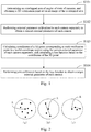
- Fig. 1 is a schematic flowchart of a method for jointly calibrating external parameters of multiple cameras according to the first embodiment of the present disclosure.
- the present embodiment is applicable to the case of joint calibration of external parameters of multiple cameras, for example, a plurality of cameras arranged in a distributed mode in a drive test perception application scenario.
- the method may be performed by an apparatus for jointly calibrating external parameters of multiple cameras, which is implemented in software and/or hardware, and is preferably configured in an electronic device, such as a computer device or a server.
- the method specifically includes the following steps.
- a distributed multi-camera scenario such as a drive test perceived application scenario
- usually a plurality of cameras are used to simultaneously capture a given location or target, such as a certain intersection. Therefore, there may be the overlapped area of the angles of view of the cameras, that is, an area that may be captured by each camera.
- the selected 2D verification point may be a point in the overlapped area, or may be a plurality of points, preferably is a point that does not participate in the calibration of camera external parameter in S102, so as to have a verification function.
- any method in the prior art may be used to separately perform external parameter calibration for a single camera, for example, a method combining the closest point matching with the minimized reprojection error to minimize the error of reprojection.
- calibration may alternatively be performed combining a specific marker, or an additional sensor to assist in calibration.
- the embodiments of the present disclosure do not make any limitation in this regard.
- the result of performing closest point matching and BA for a plurality of times has a certain randomness. For example, for a given target point on a camera image, if the 3D point corresponding to the target point in the world coordinate system is calculated based on the external parameter obtained in each calibration, as shown in (a) in Fig. 2 , point A is the true value point of the target point, and the other points are calculated 3D points corresponding to each calibration. It may be found that when the errors are the same, these 3D points may appear at different positions of the true point A.
- the ground equation and the internal parameter of the camera also need to be combined.
- the ground equation and the internal parameter of the camera may be considered as fixed truth values.
- point A is the true value point of the target point, taking the calibration of 4 cameras as an example, and the other 4 points are 3D points corresponding to the target point in the world coordinate system calculated separately based on the respective external parameters of the 4 cameras. It may be seen from (b) that when the 4 cameras independently obtain external parameters, although the error of each camera meets a requirement, the maximum error may be overlapped due to the different error directions of the cameras, such as shown by the dotted line in (b), the length of the dotted line may be used to measure the size of the overlay error.
- a verification link is added, that is, the coordinates of the 3D point corresponding to each verification point in the world coordinate system are calculated using the current external parameters of the cameras separately, and the loss function is calculated based on the coordinates of these 3D points.
- the loss function is used to measure the overlay error of calibration of the cameras under the current external parameters. That is, the smaller the loss function, the smaller the overlay error. For example, the loss function verifies whether the error between the 3D point of the verification point back to the world coordinate system and the true value of the verification point meets the requirement under the currently calculated external parameter.
- the 3D point corresponding to the verification point calculated for each camera may be obtained, and then the mean, variance or distance from the true value of these 3D points may be calculated, etc. to determine the loss function, so as to measure the overlay error in the multi-camera external parameter joint calibration process, and then determine whether the current external parameters of the cameras meet the requirement, or find a global optimal solution of joint calibration of the multi-camera external parameter through multiple iterations, so as to greatly reduce the overlay error of the external parameters.
- calculating the loss function based on the coordinates of the 3D point includes: using any verification point as a current verification point, and calculating a variance based on coordinates of a 3D point of the current verification point obtained by calculation corresponding to each camera; summing variances obtained by calculation corresponding to verification points, and using a sum value as the loss function.
- the coordinates of the 3D points of the verification point in the world coordinate system are calculated directly based on the external parameter of each camera, and the variance is calculated based on the coordinates of the 3D points to obtain the loss function.
- each verification point needs to be calculated separately. Specifically, any verification point may be used as the current verification point, and then the coordinates of the 3D points of the current verification point in the world coordinate system are calculated based on the external parameter of each camera, and the variance is calculated based on the coordinates of the respective 3D points. According to this method, after calculating each verification point separately, the calculated variances corresponding to the verification points are determined, and these variances are summed to obtain the loss function.
- the true value of the verification point in the world coordinate system may be obtained, the true value may be used as an expected value of the 3D points corresponding to the verification point, and then the variance is calculated based on the distance between the 3D points and the true value.
- the mean of the 3D points in the three directions of x, y, and z may be calculated first to obtain an optimal estimate of the true value, and then the variance is calculated based on the distance between the 3D points and the optimal estimate.
- calculating the loss function based on the coordinate of the 3D point includes: using any verification point as a current verification point, determining a distance between a 3D point of the current verification point obtained by calculation corresponding to each camera and the true value based on a truth value of the current verification point in the world coordinate system, and calculating a mean of the distance; calculating a variance based on coordinates of the 3D point of the current verification point obtained by calculation corresponding to each camera combining the truth value; weighting and summing the variance and the mean obtained by calculation corresponding to the current verification point; and summing results of the weighting and summing obtained by calculation corresponding to verification points, and using a sum value as the loss function.
- the truth value of the current verification point in the world coordinate system can be obtained.
- the distance between the 3D points and the truth value may be calculated first, and the mean of the distance may be calculated.
- the true value is used as the expected value of the 3D points corresponding to the current verification point, and the variance is calculated based on the distance between the 3D points and the true value.
- the variance obtained by calculation and the mean corresponding to the current verification point are weighted and summed, and finally, the results of the weighting and summing obtained by calculation corresponding to the verification points are summed, and the sum value is used as the loss function.
- the mean and the variance are used as part of the loss function.
- the variance may measure the degree of convergence of the 3D points
- the mean may measure the distance between the 3D points and the true value.
- the weight may be used to set the importance of both the variance and the mean to the overlay error, so as to further measure the overlay error of calibration of the cameras from the two aspects of convergence and distance from the true value, in order to improve the accuracy of finding the optimal solution of the external parameter.
- calculating the loss function based on the coordinate of the 3D point further includes: determining a minimum distance value between any two 3D points in 3D points of the current verification point obtained by calculation corresponding to each camera; and adding the loss function to the distance value corresponding to each verification point obtained by calculation, on the basis of the loss function obtained by calculation.
- another dimension is superimposed, that is, the minimum distance value between any two 3D points. Because the distance between two points may also measure the size of the overlay error, if the loss function includes this dimension, then the overlay error may be further measured from the perspective of the size of the overlay error, and similarly, the smaller the loss function, the smaller the overlay error, the better the corresponding camera external parameter.
- respective weights may alternatively be set for the three dimensions of variance, mean and distance value, and the final sum value is obtained as the loss function by weighted summation.
- the loss function is calculated based on the 3D point of a verification point mapped back to the world coordinate system, and the loss function is used to measure an overlay error of calibration of the cameras under the current external parameters.
- the loss function is the smallest, the difference of error direction of the external parameters of the current cameras may be calibrated as the smallest, which greatly reduces the overlay of errors and reduces the overlay error, so as to perform joint calibration of multi-camera based on the loss function to determine the final target external parameter and provide a good basis for subsequent multi-camera fusion.
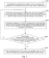
- Fig. 3 is a schematic flowchart of the method for jointly calibrating external parameters of multiple cameras according to the second embodiment of the present disclosure.
- the present embodiment is further optimized on the basis of the above embodiment.
- the method specifically includes the following steps.
- the loss function with the smallest value is selected in the loss functions obtained by multiple time of calculation, and the camera external parameter corresponding to the loss function with the smallest value is selected as the optimal solution, that is, the target external parameter.
- the number of iterations may be set in advance.
- the first iteration calibrates the external parameters of the cameras
- the loss function of this iteration is calculated based on the external parameters
- the second iteration calibrates the external parameters of the cameras
- the loss function of this iteration is calculated based on the external parameters
- the two loss functions of the first iteration and the second iteration are compared to determine which value is the smaller, and the loss function with the smaller value is saved.
- the third iteration is performed, and then the loss function corresponding to the third iteration is compared with the loss function saved last time, and the loss function with the smaller current value is saved.
- the above operation is repeated until the number of iterations meets the threshold, and the external parameters corresponding to the loss function saved at this time is used as the optimal solution.
- the loss function is calculated based on the 3D point of a verification point mapped back to the world coordinate system, and the loss function is used to measure an overlay error of calibration of the cameras under the current external parameters.
- the optimal solution is compared and selected based on the loss function obtained through multiple iterations, to find the global optimal solution of joint calibration of the multi-camera external parameter, and constrain the direction of multi-camera reprojection error in the same direction, thereby greatly reducing the overlay error of the external parameters to obtain the optimal target external parameters, which provides a good basis for subsequent multi-camera fusion.
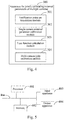
- Fig. 4 is a schematic structural diagram of an apparatus for jointly calibrating external parameters of multiple cameras according to the third embodiment of the present disclosure.
- the present embodiment is applicable to the case of joint calibration of multi-camera external parameter, for example, a plurality of cameras arranged in a distributed mode in a drive test perception application scenario.
- the apparatus may implement the method for jointly calibrating external parameters of multiple cameras described in any embodiment of the present disclosure. As shown in Fig.
- the apparatus 300 specifically includes: a verification point set acquisition module 301, configured to determine an overlapped area of angles of view of cameras, and obtain a 2D verification point set in an image of the overlapped area, the 2D verification point set including at least one verification point; a single camera external parameter calibration module 302, configured to perform external parameter calibration for each camera separately to obtain a current external parameter of each camera; a loss function calculation module 303, configured to calculate coordinates of a 3D point corresponding to each verification point in a world coordinate system using the current external parameter of each camera separately, and calculate a loss function based on the coordinates of the 3D point, the loss function being used to measure an overlay error of calibration of the cameras under the current external parameter; and a multi-camera joint calibration module 304, configured to perform joint calibration based on the loss function to obtain a target external parameter of each camera.
- a verification point set acquisition module 301 configured to determine an overlapped area of angles of view of cameras, and obtain a 2D verification point set in an image of the overlapped area, the 2D
- the multi-camera joint calibration module 304 is specifically configured to: execute repeatedly following operations until a number of executions meets a preset threshold, and using an external parameter of a camera corresponding to a loss function whose value satisfies a preset condition in loss functions obtained by calculation as the target external parameter of the camera: performing external parameter calibration for each camera separately to obtain the current external parameter of each cameras; and calculating the coordinates of the 3D point corresponding to each verification point in the world coordinate system using the current external parameter of each camera separately, and calculating the loss function based on the coordinate of the 3D point.
- the loss function calculation module 303 includes: a 3D point coordinate calculation unit, configured to calculate the coordinates of the 3D point corresponding to each verification point in the world coordinate system using the current external parameter of each camera separately; and a first loss function calculation unit, specifically configured to: use any verification point as a current verification point, and calculate a variance based on coordinates of a 3D point of the current verification point obtained by calculation corresponding to each camera; and sum variances obtained by calculation corresponding to verification points, and use a sum value as the loss function.
- a 3D point coordinate calculation unit configured to calculate the coordinates of the 3D point corresponding to each verification point in the world coordinate system using the current external parameter of each camera separately
- a first loss function calculation unit specifically configured to: use any verification point as a current verification point, and calculate a variance based on coordinates of a 3D point of the current verification point obtained by calculation corresponding to each camera; and sum variances obtained by calculation corresponding to verification points, and use a sum value as the loss function.
- the loss function calculation module 303 includes: a 3D point coordinate calculation unit, configured to calculate the coordinates of the 3D point corresponding to each verification point in the world coordinate system using the current external parameter of each camera separately; and a second loss function calculation unit, configured to: use any verification point as a current verification point, determine a distance between a 3D point of the current verification point obtained by calculation corresponding to each camera and the true value based on a truth value of the current verification point in the world coordinate system, and calculate a mean of the distance; calculate a variance based on coordinates of the 3D point of the current verification point obtained by calculation corresponding to each camera combining the truth value; weight and sum the variance and the mean obtained by calculation corresponding to the current verification point; and sum results of the weighting and summing obtained by calculation corresponding to verification points, and use a sum value as the loss function.
- a 3D point coordinate calculation unit configured to calculate the coordinates of the 3D point corresponding to each verification point in the world coordinate system using the current external parameter of each camera separately
- the loss function calculation module further includes a third loss function calculation unit, configured to: determine a minimum distance value between any two 3D points in 3D points of the current verification point obtained by calculation corresponding to each camera; and add the loss function to the distance value corresponding to each verification point obtained by calculation, on the basis of the loss function obtained by calculation by the first loss function calculation unit or the second loss function calculation unit.
- a third loss function calculation unit configured to: determine a minimum distance value between any two 3D points in 3D points of the current verification point obtained by calculation corresponding to each camera; and add the loss function to the distance value corresponding to each verification point obtained by calculation, on the basis of the loss function obtained by calculation by the first loss function calculation unit or the second loss function calculation unit.
- the single camera external parameter calibration module 302 is specifically configured to: perform external parameter calibration for each camera separately using a closest point matching method and a minimized reprojection error method to obtain the current external parameter of each camera.
- the apparatus 300 for jointly calibrating external parameters of multiple cameras provided by an embodiment of the present disclosure may execute the method for jointly calibrating external parameters of multiple cameras provided by any embodiment of the present disclosure, and has the corresponding function modules and beneficial effects to execute the method.
- the apparatus 300 for jointly calibrating external parameters of multiple cameras provided by any embodiment of the present disclosure may execute the method for jointly calibrating external parameters of multiple cameras provided by any embodiment of the present disclosure, and has the corresponding function modules and beneficial effects to execute the method.
- embodiments of the present disclosure also provide an electronic device and a readable storage medium.
- FIG. 5 is a block diagram of an electronic device for implementing the method for jointly calibrating external parameters of multiple cameras according to an embodiment of the present disclosure.
- the electronic device is intended to represent various forms of digital computers, such as laptop computers, desktop computers, workbenches, personal digital assistants, servers, blade servers, mainframe computers, and other suitable computers.
- the electronic device may also represent various forms of mobile apparatuses, such as personal digital processing, cellular phones, smart phones, wearable devices, and other similar computing apparatuses.
- the components shown herein, their connections and relationships, and their functions are merely examples, and are not intended to limit the implementation of the present disclosure described and/or claimed herein.
- the electronic device includes: one or more processors 401, a memory 402, and interfaces for connecting various components, including a high-speed interface and a low-speed interface.
- the various components are connected to each other using different buses and may be installed on a common motherboard or in other methods as needed.
- the processor may process instructions executed within the electronic device, including instructions stored in or on the memory to display GUI graphical information on an external input/output apparatus such as a display device coupled to the interface.
- a plurality of processors and/or a plurality of buses may be used with a plurality of memories if needed.
- a plurality of electronic devices may be connected, and each device provides some necessary operations (for example, as a server array, a set of blade servers, or a multi-processor system).
- One processor 401 is used as an example in Fig. 5 .
- the memory 402 is a non-transitory computer readable storage medium provided by an embodiment of the present disclosure.
- the memory stores instructions executable by at least one processor, so that the at least one processor performs the method for jointly calibrating external parameters of multiple cameras provided by the embodimens of the present disclosure.
- the non-transitory computer readable storage medium of the embodiment of the present disclosure stores computer instructions, to cause the computer to perform the method for jointly calibrating external parameters of multiple cameras provided by the present disclosure.
- the memory 402 as a non-transitory computer readable storage medium may be used to store non-transitory software programs, non-transitory computer executable programs and modules, such as program instructions/modules (for example, the verification point set acquisition module 301, the single camera external parameter calibration module 302, the loss function calculation module 303 and the multi-camera joint calibration module 304 shown in Fig. 4 ) corresponding to the method for jointly calibrating external parameters of multiple cameras in the embodiments of the present disclosure.
- the processor 401 executes non-transitory software programs, instructions, and modules stored in the memory 402 to execute various functional applications and data processing of the server, that is, to implement the method for jointly calibrating external parameters of multiple cameras in the foregoing method embodiments.
- the memory 402 may include a program storage area and a data storage area.
- the program storage area may store an operating system and an application required for at least one function.
- the data storage area may store data and the like created according to the usage of a terminal device.
- the memory 402 may include a high-speed random access memory, and may also include a non-transitory memory, e.g., at least one disk storage device, a flash memory device or other non-volatile solid-state storage devices.
- the memory 402 may further include memories remotely arranged relative to the processor 401, where the remote memories may be connected to the terminal device by a network.
- An example of the above network includes but not limited to, the Internet, an enterprise intranet, a local area network, a mobile communications network, and a combination thereof.
- the electronic device of the method for jointly calibrating external parameters of multiple cameras of the embodiments of the present disclosure may further include: an input apparatus 403 and an output apparatus 404.
- the processor 401, the memory 402, the input apparatus 403, and the output apparatus 404 may be connected via the bus or in other methods. In Fig. 4 , connection via the bus is used as an example.
- the input apparatus 403 may receive input digital or character information, and generate key signal input related to implementing user settings and function control of the electronic device of the method for jointly calibrating external parameters of multiple cameras of the embodiments of the present disclosure, for example, an input apparatuses such as a touch screen, keypad, mouse, trackpad, touchpad, pointing stick, one or more mouse buttons, trackball, or joystick.
- the output apparatus 404 may include a display device, an auxiliary lighting apparatus (for example, LED), a tactile feedback apparatus (for example, a vibration motor), or the like.
- the display device may include, but is not limited to, a liquid crystal display (LCD), a light emitting diode (LED) display, and a plasma display. In some embodiments, the display device may be a touch screen.
- Various embodiments of the systems and technologies described herein may be implemented in a digital electronic circuit system, an integrated circuit system, a dedicated ASIC (application specific integrated circuit), computer hardware, firmware, software, and/or combinations thereof. These various embodiments may include: being implemented in one or more computer programs, which may be executed and/or interpreted on a programmable system including at least one programmable processor.
- the programmable processor may be a dedicated or general-purpose programmable processor, which may receive data and instructions from a storage system, at least one input apparatus, and at least one output apparatus, and transmit the data and instructions to the storage system, the at least one input apparatus, and the at least one output apparatus.
- These computing programs include machine instructions of the programmable processor, and may use high-level processes and/or object-oriented programming languages, and/or assembly/machine languages to implement these computing programs.
- machine readable medium and “computer readable medium” refer to any computer program product, device, and/or apparatus (for example, magnetic disk, optical disk, memory, programmable logic device (PLD)) used to provide machine instructions and/or data to the programmable processor, including machine readable medium that receives machine instructions as machine readable signals.
- machine readable signal refers to any signal used to provide the machine instructions and/or data to the programmable processor.
- the systems and technologies described herein may be implemented on a computer, and the computer has: a display apparatus (e.g., CRT (cathode ray tube) or LCD (liquid crystal display) monitor) for displaying information to the user; and a keyboard and a pointing apparatus (for example, a mouse or trackball), and the user may use the keyboard and the pointing apparatus to provide input to the computer.
- a display apparatus e.g., CRT (cathode ray tube) or LCD (liquid crystal display) monitor
- a keyboard and a pointing apparatus for example, a mouse or trackball
- Other kinds of apparatuses may also be used to provide interaction with the user; for example, the feedback provided to the user may be any form of sensory feedback (for example, visual feedback, auditory feedback, or tactile feedback); and may use any form (including acoustic input, voice input, or tactile input) to receive input from the user.
- the systems and technologies described herein may be implemented in a computing system (e.g., as a data server) that includes back-end components, or a computing system (e.g., an application server) that includes middleware components, or a computing system (for example, a user computer with a graphical user interface or a web browser, through which the user may interact with the embodiments of the systems and technologies described herein) that includes front-end components, or a computing system that includes any combination of such back-end components, middleware components, or front-end components.
- the components of the system may be interconnected by any form or medium of digital data communication (e.g., a communication network). Examples of the communication network include: local area network (LAN), wide area network (WAN), and Internet.
- the computer system may include a client and a server.
- the client and the server are generally far from each other and usually interact through a communication network.
- the client and server relationship is generated by computer programs operating on the corresponding computer and having client-server relationship with each other.
- a loss function is calculated based on the 3D point of a verification point mapped back to the world coordinate system, and the loss function is used to measure an overlay error of calibration of the cameras under the current external parameters, thus playing certain verification function, and multi-camera joint calibration is performed based on the loss function to determine a final target external parameter, which largely eliminates the overlay of multi-camera errors and provides a good basis for subsequent multi-camera fusion.
Landscapes
- Engineering & Computer Science (AREA)
- Physics & Mathematics (AREA)
- General Physics & Mathematics (AREA)
- Theoretical Computer Science (AREA)
- Computer Vision & Pattern Recognition (AREA)
- Data Mining & Analysis (AREA)
- Pure & Applied Mathematics (AREA)
- Computational Mathematics (AREA)
- Mathematical Physics (AREA)
- Mathematical Optimization (AREA)
- Mathematical Analysis (AREA)
- Operations Research (AREA)
- Databases & Information Systems (AREA)
- Evolutionary Biology (AREA)
- General Engineering & Computer Science (AREA)
- Bioinformatics & Computational Biology (AREA)
- Bioinformatics & Cheminformatics (AREA)
- Probability & Statistics with Applications (AREA)
- Software Systems (AREA)
- Algebra (AREA)
- Life Sciences & Earth Sciences (AREA)
- Human Computer Interaction (AREA)
- Signal Processing (AREA)
- Multimedia (AREA)
- Studio Devices (AREA)
Abstract
Description
- This application claims priority to Chinese Patent Application No.
201910955707.0, filed on October 9, 2019 - The present disclosure relates to image processing technology and is applicable in the field of autonomous driving, specifically relates to a camera external parameter calibration technology, and more specifically to a method and apparatus for jointly calibrating external parameters of multiple cameras, device and medium.
- Camera external parameter calibration refers to that after a camera is installed, a transformation matrix (composed of a rotation matrix and a translation vector) of the world coordinate system to the camera coordinate system is obtained by a certain method. This transformation matrix is the external parameter of a camera. The external parameter of the camera is a necessary condition to connect the position of an object in the real world and a pixel position in an image. It is very important in the fields where the position of an object in the image needs to be located, such as autonomous driving or security. Therefore, it is necessary to calculate accurate external parameter of the camera.
- Embodiments of the present disclosure provide a method and apparatus for jointly calibrating external parameters of multiple cameras, device and medium, so as to reduce an overlay error of the multi-camera external parameter.
- An embodiment of the present disclosure provides a method for jointly calibrating external parameters of multiple cameras, the method including: determining an overlapped area of angles of view of cameras, and obtaining a two-dimensional (2D) verification point set in an image of the overlapped area, the 2D verification point set comprising at least one verification point; performing external parameter calibration for each camera separately to obtain a current external parameter of each camera; calculating coordinates of a three-dimensional (3D) point corresponding to each verification point in a world coordinate system using the current external parameter of each camera separately, and calculating a loss function based on the coordinates of the 3D point, the loss function being used to measure an overlay error of calibration of the cameras under the current external parameter; and performing joint calibration based on the loss function to obtain a target external parameter of each camera.
- The above embodiment of the disclosure has the following advantages or beneficial effects: by adding a verification link on the basis of the existing technology, a loss function is calculated based on the 3D point of a verification point mapped back to the world coordinate system, and the loss function is used to measure an overlay error of calibration of the cameras under the current external parameters, thus playing certain verification function, and multi-camera joint calibration is performed based on the loss function to determine a final target external parameter, which largely eliminates the overlay of multi-camera errors and provides a good basis for subsequent multi-camera fusion.
- Alternatively, the performing joint calibration based on the loss function to obtain a target external parameter of each cameras, includes: executing repeatedly following operations until a number of executions meets a preset threshold, and using an external parameter of an cameras corresponding to a loss function whose value satisfies a preset condition in loss functions obtained by calculation as the target external parameter of the camera: performing external parameter calibration for each camera separately to obtain the current external parameter of each camera; and calculating the coordinates of the 3D point corresponding to each verification point in the world coordinate system using the current external parameter of each camera separately, and calculating the loss function based on the coordinates of the 3D point.
- The above embodiment of the disclosure has the following advantages or beneficial effects: by iterating a plurality of times to find each loss function, and finding the optimal solution from the loss functions, the optimal camera external parameters are obtained.
- Alternatively, calculating the loss function based on the coordinates of the 3D point, includes: using any verification point as a current verification point, and calculating a variance based on coordinates of a 3D point of the current verification point obtained by calculation corresponding to each camera; and summing variances obtained by calculation corresponding to verification points, and using a sum value as the loss function.
- The above embodiment of the disclosure has the following advantages or beneficial effects: without knowing the true value of the verification point in the world coordinate system, the calculation of the variance is used to measure the degree of convergence of the 3D points mapped by the cameras for the same verification point in the world coordinate system. The better the degree of convergence is, it shows that the reprojection errors of the cameras are more tend to be in the same direction, and the smaller the overlay error is, so that it plays a measuring and verifying function to the overlay error of calibration of the cameras under the current external parameters through the loss function.
- Alternatively, calculating the loss function based on the coordinates of the 3D point, includes: using any verification point as a current verification point, determining a distance between a 3D point of the current verification point obtained by calculation corresponding to each camera and the true value based on a truth value of the current verification point in the world coordinate system, and calculating a mean of the distance; calculating a variance based on coordinates of the 3D point of the current verification point obtained by calculation corresponding to each camera combining the truth value; weighting and summing the variance and the mean obtained by calculation corresponding to the current verification point; and summing results of the weighting and summing obtained by calculation corresponding to verification points, and using a sum value as the loss function.
- The above embodiment of the disclosure has the following advantages or beneficial effects: in the case that the true value of the verification point in the world coordinate system can be obtained, the mean and variance are together used as part of the loss function. The variance may measure the degree of convergence of the 3D points, and the mean may measure the distance between the 3D points and the true value. In order to improve the accuracy of finding the optimal solution of the external parameter, the overlay error of calibration of the cameras are further measured from the two angles of convergence degree and distance from the true value.
- Alternatively, calculating the loss function based on the coordinates of the 3D point, further includes: determining a minimum distance value between any two 3D points in 3D points of the current verification point obtained by calculation corresponding to each camera; and adding the loss function to the distance value corresponding to each verification point obtained by calculation, on the basis of the loss function obtained by calculation.
- The above embodiment of the disclosure has the following advantages or beneficial effects: on the basis of calculating the loss function through the variance and the mean, an additional dimension is added, that is, the distance between any two 3D points, because if the distance between any two 3D points is smaller, the dimension indicates that the overlay error of the external parameters is smaller, thereby further improving the accuracy of measuring the overlay error by the loss function.
- Alternatively, the performing external parameter calibration for each camera separately to obtain the current external parameter of each camera, includes: performing external parameter calibration for each camera separately using a closest point matching method and a minimized reprojection error method to obtain the current external parameter of each camera.
- In a second aspect, an embodiment of the present disclosure provides an apparatus for jointly calibrating external parameters of multiple cameras, the apparatus including: a verification point set acquisition module, configured to determine an overlapped area of angles of view of cameras, and obtain a two-dimensional (2D) verification point set in an image of the overlapped area, the 2D verification point set including at least one verification point; a single camera external parameter calibration module, configured to perform external parameter calibration for each camera separately to obtain a current external parameter of each cameras; a loss function calculation module, configured to calculate a coordinate of a three-dimensional (3D) point corresponding to each verification point in a world coordinate system using the current external parameter of each cameras separately, and calculate a loss function based on the coordinates of the 3D point, the loss function being used to measure an overlay error of calibration of the cameras under the current external parameter; and a multi-camera joint calibration module, configured to perform joint calibration based on the loss function to obtain a target external parameter of each camera.
- In a third aspect, an embodiment of the present disclosure provides an electronic device, including: at least one processor; and a storage apparatus, in communication connection with the at least one processor; the storage apparatus, storing instructions executable by the at least one processor, the instructions, when executed by the at least one processor, cause the at least one processor to implement the method for jointly calibrating external parameters of multiple cameras according to any embodiment of the present disclosure.
- Embodiments of the disclosure have the following advantages or beneficial effects: by adding a verification link on the basis of the existing technology, and determining the optimal external parameter of the camera joint calibration through the result of the verification point set back to 3D, it solves the limitation problem of considering only single camera reprojection error in single camera calibration in the past, which largely eliminates the overlay of multi-camera errors and provides a good basis for subsequent multi-camera fusion.
- Other effects possessed by the above alternative methods will be described below in conjunction with specific embodiments.
- The accompanying drawings are used to better understand the present solution and do not constitute a limitation of the present disclosure.
-
Fig. 1 is a schematic flowchart of a method for jointly calibrating external parameters of multiple cameras according to a first embodiment of the present disclosure; -
Fig. 2 is a schematic diagram of an overlay error of multi-camera calibration in the first embodiment of the present disclosure; -
Fig. 3 is a schematic flowchart of the method for jointly calibrating external parameters of multiple cameras according to a second embodiment of the present disclosure; -
Fig. 4 is a schematic structural diagram of an apparatus for jointly calibrating external parameters of multiple cameras according to a third embodiment of the present disclosure; and -
Fig. 5 is a block diagram of an electronic device for implementing the method for jointly calibrating a external parameters of multiple cameras according to an embodiment of the present disclosure. - The following describes exemplary embodiments of the present disclosure with reference to the accompanying drawings, which includes various details of embodiments of the present disclosure to facilitate understanding, and they should be considered as merely exemplary. Therefore, those of ordinary skills in the art should recognize that various changes and modifications may be made to the embodiments described herein without departing from the scope and spirit of the present disclosure. Also, for clarity and conciseness, descriptions of well-known functions and structures are omitted in the following description.
- In scenarios of calculating camera external parameters, there are some application scenarios that require distributed multi-camera to shoot the same scenario from different positions and angles, such as roadside perception, that is, a plurality of cameras are distributed at the intersection, subsequently, multi-camera fusion is then performed to locate the target in this scenario. However, there may be error in the external parameter calibration of a single camera, then in distributed multi-camera calibration, the maximum error of the external parameter calibration of different cameras may be overlapped, resulting in inaccuracy of the target returning to 3D position, which may affect subsequent multi-camera fusion. However, in embodiments of the present disclosure, by adding a verification link on the basis of the existing technology, and determining the optimal external parameter of the camera joint calibration through the result of the verification point set back to 3D, it solves the limitation problem of considering only single camera reprojection error in single camera calibration in the past, which largely eliminates the overlay of multi-camera errors and provides a good basis for subsequent multi-camera fusion.
-
Fig. 1 is a schematic flowchart of a method for jointly calibrating external parameters of multiple cameras according to the first embodiment of the present disclosure. The present embodiment is applicable to the case of joint calibration of external parameters of multiple cameras, for example, a plurality of cameras arranged in a distributed mode in a drive test perception application scenario. The method may be performed by an apparatus for jointly calibrating external parameters of multiple cameras, which is implemented in software and/or hardware, and is preferably configured in an electronic device, such as a computer device or a server. As shown inFig. 1 , the method specifically includes the following steps. - S101, determining an overlapped area of angles of view of cameras, and obtaining a two-dimensional (2D) verification point set in an image of the overlapped area, the 2D verification point set including at least one verification point.
- In a distributed multi-camera scenario, such as a drive test perceived application scenario, usually a plurality of cameras are used to simultaneously capture a given location or target, such as a certain intersection. Therefore, there may be the overlapped area of the angles of view of the cameras, that is, an area that may be captured by each camera. The selected 2D verification point may be a point in the overlapped area, or may be a plurality of points, preferably is a point that does not participate in the calibration of camera external parameter in S102, so as to have a verification function.
- S102, performing external parameter calibration for each camera separately to obtain a current external parameters of each camera.
- Here, any method in the prior art may be used to separately perform external parameter calibration for a single camera, for example, a method combining the closest point matching with the minimized reprojection error to minimize the error of reprojection. In addition, calibration may alternatively be performed combining a specific marker, or an additional sensor to assist in calibration. The embodiments of the present disclosure do not make any limitation in this regard.
- S103, calculating coordinates of a three-dimensional (3D) point corresponding to each verification point in a world coordinate system using the current external parameter of each camera separately, and calculating a loss function based on the coordinate of the 3D point, the loss function being used to measure an overlay error of calibration of the camera under the current external parameter.
- S104, performing joint calibration based on the loss function to obtain a target external parameter of each camera.
- For example, performing external parameter calibration using the method of closest point matching combined with solution to minimize reprojection error (BA, Bundle Adjustment). Due to the uncertainty of closest point matching, the result of performing closest point matching and BA for a plurality of times has a certain randomness. For example, for a given target point on a camera image, if the 3D point corresponding to the target point in the world coordinate system is calculated based on the external parameter obtained in each calibration, as shown in (a) in
Fig. 2 , point A is the true value point of the target point, and the other points are calculated 3D points corresponding to each calibration. It may be found that when the errors are the same, these 3D points may appear at different positions of the true point A. It should also be noted that, in the process of calculating the 3D points corresponding to the world coordinate system based on the external parameters, the ground equation and the internal parameter of the camera also need to be combined. In the embodiments of the present disclosure, the ground equation and the internal parameter of the camera may be considered as fixed truth values. - Further, as shown in (b) of
Fig. 2 , similarly, point A is the true value point of the target point, taking the calibration of 4 cameras as an example, and the other 4 points are 3D points corresponding to the target point in the world coordinate system calculated separately based on the respective external parameters of the 4 cameras. It may be seen from (b) that when the 4 cameras independently obtain external parameters, although the error of each camera meets a requirement, the maximum error may be overlapped due to the different error directions of the cameras, such as shown by the dotted line in (b), the length of the dotted line may be used to measure the size of the overlay error. - Therefore, in the embodiments of the present disclosure, after calculating the external parameter of a single camera, a verification link is added, that is, the coordinates of the 3D point corresponding to each verification point in the world coordinate system are calculated using the current external parameters of the cameras separately, and the loss function is calculated based on the coordinates of these 3D points. The loss function is used to measure the overlay error of calibration of the cameras under the current external parameters. That is, the smaller the loss function, the smaller the overlay error. For example, the loss function verifies whether the error between the 3D point of the verification point back to the world coordinate system and the true value of the verification point meets the requirement under the currently calculated external parameter. Furthermore, in the joint calibration of multi-camera external parameter, the 3D point corresponding to the verification point calculated for each camera may be obtained, and then the mean, variance or distance from the true value of these 3D points may be calculated, etc. to determine the loss function, so as to measure the overlay error in the multi-camera external parameter joint calibration process, and then determine whether the current external parameters of the cameras meet the requirement, or find a global optimal solution of joint calibration of the multi-camera external parameter through multiple iterations, so as to greatly reduce the overlay error of the external parameters.
- As an embodiment of calculating the loss function, calculating the loss function based on the coordinates of the 3D point includes: using any verification point as a current verification point, and calculating a variance based on coordinates of a 3D point of the current verification point obtained by calculation corresponding to each camera; summing variances obtained by calculation corresponding to verification points, and using a sum value as the loss function.
- If only one verification point is included in the verification point set, the coordinates of the 3D points of the verification point in the world coordinate system are calculated directly based on the external parameter of each camera, and the variance is calculated based on the coordinates of the 3D points to obtain the loss function.
- If more than two verification points are included in the verification point set, each verification point needs to be calculated separately. Specifically, any verification point may be used as the current verification point, and then the coordinates of the 3D points of the current verification point in the world coordinate system are calculated based on the external parameter of each camera, and the variance is calculated based on the coordinates of the respective 3D points. According to this method, after calculating each verification point separately, the calculated variances corresponding to the verification points are determined, and these variances are summed to obtain the loss function.
- Here, it should be noted that by calculating the variance, it is possible to measure the degree of convergence of the 3D points mapped by the cameras for the same verification point in the world coordinate system. It may be seen from (c) in
Fig. 2 that the better the degree of convergence, the reprojection errors of the cameras are more tend to be in the same direction, and the smaller the overlay error (as shown by the dotted line in the figure). Thereby, it plays a measuring and verifying function to the overlay error of calibration of the cameras under the current external parameters through the loss function, that is, the smaller the loss function, the smaller the overlay error, and the corresponding external parameter is optimal. - In addition, regarding the calculation of the variance, two cases may be included. For the case where the true value of the verification point in the world coordinate system can be obtained, the true value may be used as an expected value of the 3D points corresponding to the verification point, and then the variance is calculated based on the distance between the 3D points and the true value. For the case where the true value of the verification point cannot be obtained, the mean of the 3D points in the three directions of x, y, and z may be calculated first to obtain an optimal estimate of the true value, and then the variance is calculated based on the distance between the 3D points and the optimal estimate.
- As another embodiment of calculating the loss function, calculating the loss function based on the coordinate of the 3D point includes: using any verification point as a current verification point, determining a distance between a 3D point of the current verification point obtained by calculation corresponding to each camera and the true value based on a truth value of the current verification point in the world coordinate system, and calculating a mean of the distance; calculating a variance based on coordinates of the 3D point of the current verification point obtained by calculation corresponding to each camera combining the truth value; weighting and summing the variance and the mean obtained by calculation corresponding to the current verification point; and summing results of the weighting and summing obtained by calculation corresponding to verification points, and using a sum value as the loss function.
- In this embodiment, the truth value of the current verification point in the world coordinate system can be obtained. In this regard, the distance between the 3D points and the truth value may be calculated first, and the mean of the distance may be calculated. Then, similarly, the true value is used as the expected value of the 3D points corresponding to the current verification point, and the variance is calculated based on the distance between the 3D points and the true value. The variance obtained by calculation and the mean corresponding to the current verification point are weighted and summed, and finally, the results of the weighting and summing obtained by calculation corresponding to the verification points are summed, and the sum value is used as the loss function.
- It should be noted that, in the case that the true value of the verification point in the world coordinate system can be obtained, the mean and the variance are used as part of the loss function. The variance may measure the degree of convergence of the 3D points, and the mean may measure the distance between the 3D points and the true value. The weight may be used to set the importance of both the variance and the mean to the overlay error, so as to further measure the overlay error of calibration of the cameras from the two aspects of convergence and distance from the true value, in order to improve the accuracy of finding the optimal solution of the external parameter.
- In addition, in another embodiment, calculating the loss function based on the coordinate of the 3D point, further includes: determining a minimum distance value between any two 3D points in 3D points of the current verification point obtained by calculation corresponding to each camera; and adding the loss function to the distance value corresponding to each verification point obtained by calculation, on the basis of the loss function obtained by calculation.
- Specifically, in this embodiment, on the basis of the loss function that has been calculated, another dimension is superimposed, that is, the minimum distance value between any two 3D points. Because the distance between two points may also measure the size of the overlay error, if the loss function includes this dimension, then the overlay error may be further measured from the perspective of the size of the overlay error, and similarly, the smaller the loss function, the smaller the overlay error, the better the corresponding camera external parameter. In addition, respective weights may alternatively be set for the three dimensions of variance, mean and distance value, and the final sum value is obtained as the loss function by weighted summation.
- The technical solution of the embodiments of the present disclosure, by adding a verification link on the basis of the existing technology, the loss function is calculated based on the 3D point of a verification point mapped back to the world coordinate system, and the loss function is used to measure an overlay error of calibration of the cameras under the current external parameters. When the loss function is the smallest, the difference of error direction of the external parameters of the current cameras may be calibrated as the smallest, which greatly reduces the overlay of errors and reduces the overlay error, so as to perform joint calibration of multi-camera based on the loss function to determine the final target external parameter and provide a good basis for subsequent multi-camera fusion.
-
Fig. 3 is a schematic flowchart of the method for jointly calibrating external parameters of multiple cameras according to the second embodiment of the present disclosure. The present embodiment is further optimized on the basis of the above embodiment. As shown inFig. 3 , the method specifically includes the following steps. - S201, determining an overlapped area of angles of view of cameras, and obtaining a 2D verification point set in an image of the overlapped area, the 2D verification point set including at least one verification point.
- S202, performing external parameter calibration for each camera separately using a closest point matching method and a minimized reprojection error method to obtain a current external parameter of each camera.
- S203, calculating coordinates of a 3D point corresponding to each verification point in a world coordinate system using the current external parameters of the cameras separately, and calculating a loss function based on the coordinates of the 3D point.
- S204, determining and saving a loss function with the smallest current value, and determining whether the current number of executions meets a preset threshold, if not, return to execute step S202, and if yes, execute step S205.
- S205, using external parameters of the cameras corresponding to the currently saved loss function as the target external parameters of the cameras.
- In the present embodiment, through multiple iterations of the camera external parameter, the loss function with the smallest value is selected in the loss functions obtained by multiple time of calculation, and the camera external parameter corresponding to the loss function with the smallest value is selected as the optimal solution, that is, the target external parameter.
- Specifically, the number of iterations may be set in advance. For example, the first iteration calibrates the external parameters of the cameras, the loss function of this iteration is calculated based on the external parameters, and the second iteration calibrates the external parameters of the cameras, the loss function of this iteration is calculated based on the external parameters, then the two loss functions of the first iteration and the second iteration are compared to determine which value is the smaller, and the loss function with the smaller value is saved. Then, the third iteration is performed, and then the loss function corresponding to the third iteration is compared with the loss function saved last time, and the loss function with the smaller current value is saved. The above operation is repeated until the number of iterations meets the threshold, and the external parameters corresponding to the loss function saved at this time is used as the optimal solution.
- The technical solution of the embodiments of the present disclosure, by adding a verification to obtain the optimal solution link on the basis of the existing technology, the loss function is calculated based on the 3D point of a verification point mapped back to the world coordinate system, and the loss function is used to measure an overlay error of calibration of the cameras under the current external parameters. The optimal solution is compared and selected based on the loss function obtained through multiple iterations, to find the global optimal solution of joint calibration of the multi-camera external parameter, and constrain the direction of multi-camera reprojection error in the same direction, thereby greatly reducing the overlay error of the external parameters to obtain the optimal target external parameters, which provides a good basis for subsequent multi-camera fusion.
-
Fig. 4 is a schematic structural diagram of an apparatus for jointly calibrating external parameters of multiple cameras according to the third embodiment of the present disclosure. The present embodiment is applicable to the case of joint calibration of multi-camera external parameter, for example, a plurality of cameras arranged in a distributed mode in a drive test perception application scenario. The apparatus may implement the method for jointly calibrating external parameters of multiple cameras described in any embodiment of the present disclosure. As shown inFig. 4 , theapparatus 300 specifically includes: a verification point setacquisition module 301, configured to determine an overlapped area of angles of view of cameras, and obtain a 2D verification point set in an image of the overlapped area, the 2D verification point set including at least one verification point; a single camera externalparameter calibration module 302, configured to perform external parameter calibration for each camera separately to obtain a current external parameter of each camera; a lossfunction calculation module 303, configured to calculate coordinates of a 3D point corresponding to each verification point in a world coordinate system using the current external parameter of each camera separately, and calculate a loss function based on the coordinates of the 3D point, the loss function being used to measure an overlay error of calibration of the cameras under the current external parameter; and a multi-camerajoint calibration module 304, configured to perform joint calibration based on the loss function to obtain a target external parameter of each camera. - Alternatively, the multi-camera
joint calibration module 304 is specifically configured to: execute repeatedly following operations until a number of executions meets a preset threshold, and using an external parameter of a camera corresponding to a loss function whose value satisfies a preset condition in loss functions obtained by calculation as the target external parameter of the camera: performing external parameter calibration for each camera separately to obtain the current external parameter of each cameras; and calculating the coordinates of the 3D point corresponding to each verification point in the world coordinate system using the current external parameter of each camera separately, and calculating the loss function based on the coordinate of the 3D point. - Alternatively, the loss
function calculation module 303 includes: a 3D point coordinate calculation unit, configured to calculate the coordinates of the 3D point corresponding to each verification point in the world coordinate system using the current external parameter of each camera separately; and a first loss function calculation unit, specifically configured to: use any verification point as a current verification point, and calculate a variance based on coordinates of a 3D point of the current verification point obtained by calculation corresponding to each camera; and sum variances obtained by calculation corresponding to verification points, and use a sum value as the loss function. - Alternatively, the loss
function calculation module 303 includes: a 3D point coordinate calculation unit, configured to calculate the coordinates of the 3D point corresponding to each verification point in the world coordinate system using the current external parameter of each camera separately; and a second loss function calculation unit, configured to: use any verification point as a current verification point, determine a distance between a 3D point of the current verification point obtained by calculation corresponding to each camera and the true value based on a truth value of the current verification point in the world coordinate system, and calculate a mean of the distance; calculate a variance based on coordinates of the 3D point of the current verification point obtained by calculation corresponding to each camera combining the truth value; weight and sum the variance and the mean obtained by calculation corresponding to the current verification point; and sum results of the weighting and summing obtained by calculation corresponding to verification points, and use a sum value as the loss function. - Alternatively, the loss function calculation module further includes a third loss function calculation unit, configured to: determine a minimum distance value between any two 3D points in 3D points of the current verification point obtained by calculation corresponding to each camera; and add the loss function to the distance value corresponding to each verification point obtained by calculation, on the basis of the loss function obtained by calculation by the first loss function calculation unit or the second loss function calculation unit.
- Alternatively, the single camera external
parameter calibration module 302 is specifically configured to: perform external parameter calibration for each camera separately using a closest point matching method and a minimized reprojection error method to obtain the current external parameter of each camera. - The
apparatus 300 for jointly calibrating external parameters of multiple cameras provided by an embodiment of the present disclosure may execute the method for jointly calibrating external parameters of multiple cameras provided by any embodiment of the present disclosure, and has the corresponding function modules and beneficial effects to execute the method. For content that is not described in detail in the present embodiment, reference may be made to the description in any method embodiment of the present disclosure. - According to the embodiments of the present disclosure, embodiments of the present disclosure also provide an electronic device and a readable storage medium.
- As shown in
Fig. 5 , is a block diagram of an electronic device for implementing the method for jointly calibrating external parameters of multiple cameras according to an embodiment of the present disclosure. The electronic device is intended to represent various forms of digital computers, such as laptop computers, desktop computers, workbenches, personal digital assistants, servers, blade servers, mainframe computers, and other suitable computers. The electronic device may also represent various forms of mobile apparatuses, such as personal digital processing, cellular phones, smart phones, wearable devices, and other similar computing apparatuses. The components shown herein, their connections and relationships, and their functions are merely examples, and are not intended to limit the implementation of the present disclosure described and/or claimed herein. - As shown in
Fig. 5 , the electronic device includes: one ormore processors 401, amemory 402, and interfaces for connecting various components, including a high-speed interface and a low-speed interface. The various components are connected to each other using different buses and may be installed on a common motherboard or in other methods as needed. The processor may process instructions executed within the electronic device, including instructions stored in or on the memory to display GUI graphical information on an external input/output apparatus such as a display device coupled to the interface. In other embodiments, a plurality of processors and/or a plurality of buses may be used with a plurality of memories if needed. Similarly, a plurality of electronic devices may be connected, and each device provides some necessary operations (for example, as a server array, a set of blade servers, or a multi-processor system). Oneprocessor 401 is used as an example inFig. 5 . - The
memory 402 is a non-transitory computer readable storage medium provided by an embodiment of the present disclosure. Here, the memory stores instructions executable by at least one processor, so that the at least one processor performs the method for jointly calibrating external parameters of multiple cameras provided by the embodimens of the present disclosure. The non-transitory computer readable storage medium of the embodiment of the present disclosure stores computer instructions, to cause the computer to perform the method for jointly calibrating external parameters of multiple cameras provided by the present disclosure. - The
memory 402 as a non-transitory computer readable storage medium may be used to store non-transitory software programs, non-transitory computer executable programs and modules, such as program instructions/modules (for example, the verification point setacquisition module 301, the single camera externalparameter calibration module 302, the lossfunction calculation module 303 and the multi-camerajoint calibration module 304 shown inFig. 4 ) corresponding to the method for jointly calibrating external parameters of multiple cameras in the embodiments of the present disclosure. Theprocessor 401 executes non-transitory software programs, instructions, and modules stored in thememory 402 to execute various functional applications and data processing of the server, that is, to implement the method for jointly calibrating external parameters of multiple cameras in the foregoing method embodiments. - The
memory 402 may include a program storage area and a data storage area. The program storage area may store an operating system and an application required for at least one function. The data storage area may store data and the like created according to the usage of a terminal device. In addition, thememory 402 may include a high-speed random access memory, and may also include a non-transitory memory, e.g., at least one disk storage device, a flash memory device or other non-volatile solid-state storage devices. In some embodiments, thememory 402 may further include memories remotely arranged relative to theprocessor 401, where the remote memories may be connected to the terminal device by a network. An example of the above network includes but not limited to, the Internet, an enterprise intranet, a local area network, a mobile communications network, and a combination thereof. - The electronic device of the method for jointly calibrating external parameters of multiple cameras of the embodiments of the present disclosure may further include: an
input apparatus 403 and anoutput apparatus 404. Theprocessor 401, thememory 402, theinput apparatus 403, and theoutput apparatus 404 may be connected via the bus or in other methods. InFig. 4 , connection via the bus is used as an example. - The
input apparatus 403 may receive input digital or character information, and generate key signal input related to implementing user settings and function control of the electronic device of the method for jointly calibrating external parameters of multiple cameras of the embodiments of the present disclosure, for example, an input apparatuses such as a touch screen, keypad, mouse, trackpad, touchpad, pointing stick, one or more mouse buttons, trackball, or joystick. Theoutput apparatus 404 may include a display device, an auxiliary lighting apparatus (for example, LED), a tactile feedback apparatus (for example, a vibration motor), or the like. The display device may include, but is not limited to, a liquid crystal display (LCD), a light emitting diode (LED) display, and a plasma display. In some embodiments, the display device may be a touch screen. - Various embodiments of the systems and technologies described herein may be implemented in a digital electronic circuit system, an integrated circuit system, a dedicated ASIC (application specific integrated circuit), computer hardware, firmware, software, and/or combinations thereof. These various embodiments may include: being implemented in one or more computer programs, which may be executed and/or interpreted on a programmable system including at least one programmable processor. The programmable processor may be a dedicated or general-purpose programmable processor, which may receive data and instructions from a storage system, at least one input apparatus, and at least one output apparatus, and transmit the data and instructions to the storage system, the at least one input apparatus, and the at least one output apparatus.
- These computing programs (also referred to as programs, software, software applications, or codes) include machine instructions of the programmable processor, and may use high-level processes and/or object-oriented programming languages, and/or assembly/machine languages to implement these computing programs. As used herein, the terms "machine readable medium" and "computer readable medium" refer to any computer program product, device, and/or apparatus (for example, magnetic disk, optical disk, memory, programmable logic device (PLD)) used to provide machine instructions and/or data to the programmable processor, including machine readable medium that receives machine instructions as machine readable signals. The term "machine readable signal" refers to any signal used to provide the machine instructions and/or data to the programmable processor.
- In order to provide interaction with a user, the systems and technologies described herein may be implemented on a computer, and the computer has: a display apparatus (e.g., CRT (cathode ray tube) or LCD (liquid crystal display) monitor) for displaying information to the user; and a keyboard and a pointing apparatus (for example, a mouse or trackball), and the user may use the keyboard and the pointing apparatus to provide input to the computer. Other kinds of apparatuses may also be used to provide interaction with the user; for example, the feedback provided to the user may be any form of sensory feedback (for example, visual feedback, auditory feedback, or tactile feedback); and may use any form (including acoustic input, voice input, or tactile input) to receive input from the user.
- The systems and technologies described herein may be implemented in a computing system (e.g., as a data server) that includes back-end components, or a computing system (e.g., an application server) that includes middleware components, or a computing system (for example, a user computer with a graphical user interface or a web browser, through which the user may interact with the embodiments of the systems and technologies described herein) that includes front-end components, or a computing system that includes any combination of such back-end components, middleware components, or front-end components. The components of the system may be interconnected by any form or medium of digital data communication (e.g., a communication network). Examples of the communication network include: local area network (LAN), wide area network (WAN), and Internet.
- The computer system may include a client and a server. The client and the server are generally far from each other and usually interact through a communication network. The client and server relationship is generated by computer programs operating on the corresponding computer and having client-server relationship with each other.
- The technical solution according to the embodiments of the present disclosure, by adding a verification link on the basis of the existing technology, a loss function is calculated based on the 3D point of a verification point mapped back to the world coordinate system, and the loss function is used to measure an overlay error of calibration of the cameras under the current external parameters, thus playing certain verification function, and multi-camera joint calibration is performed based on the loss function to determine a final target external parameter, which largely eliminates the overlay of multi-camera errors and provides a good basis for subsequent multi-camera fusion.
- It should be understood that various forms of processes shown above may be used to reorder, add, or delete steps. For example, the steps described in the present disclosure may be performed in parallel, sequentially, or in different orders, as long as the desired results of the technical solution disclosed in the present disclosure can be achieved, no limitation is made herein.
- The above specific embodiments do not constitute a limitation on the protection scope of the present disclosure. Those skilled in the art should understand that various modifications, combinations, sub-combinations and substitutions may be made according to design requirements and other factors. Any modification, and improvement made within the principle of the present disclosure shall be included in the protection scope of the present disclosure.
Claims (13)
- A method for jointly calibrating external parameters of multiple cameras, the method comprising:determining (S101) an overlapped area of angles of view of cameras, and obtaining a two-dimensional, 2D, verification point set in an image of the overlapped area, the 2D verification point set comprising at least one verification point;performing (S102) external parameter calibration for each camera separately to obtain a current external parameter of each camera;calculating (S103) coordinates of a three-dimensional, 3D, point corresponding to each verification point in a world coordinate system using the current external parameter of each camera separately, and calculating a loss function based on the coordinates of the 3D point, the loss function being used to measure an overlay error of calibration of the cameras under the current external parameter; andperforming (S104) joint calibration based on the loss function to obtain a target external parameter of each camera.
- The method according to claim 1, wherein the performing joint calibration based on the loss function to obtain a target external parameter of each cameras, comprises:
executing repeatedly following operations until a number of executions meets a preset threshold, and using an external parameter of an cameras corresponding to a loss function whose value satisfies a preset condition in loss functions obtained by calculation as the target external parameter of the camera:performing external parameter calibration for each camera separately to obtain the current external parameter of each camera; andcalculating the coordinates of the 3D point corresponding to each verification point in the world coordinate system using the current external parameter of each camera separately, and calculating the loss function based on the coordinates of the 3D point. - The method according to claim 1 or 2, wherein calculating the loss function based on the coordinates of the 3D point, comprises:using any verification point as a current verification point, determining a distance between a 3D point of the current verification point obtained by calculation corresponding to each camera and the true value based on a truth value of the current verification point in the world coordinate system, and calculating a mean of the distance;calculating a variance based on coordinates of the 3D point of the current verification point obtained by calculation corresponding to each camera combining the truth value;weighting and summing the variance and the mean obtained by calculation corresponding to the current verification point; andsumming results of the weighting and summing obtained by calculation corresponding to verification points, and using a sum value as the loss function.
- The method according to claim 1 or 2, wherein calculating the loss function based on the coordinates of the 3D point, comprises:using any verification point as a current verification point, and calculating a variance based on coordinates of a 3D point of the current verification point obtained by calculation corresponding to each camera; andsumming variances obtained by calculation corresponding to verification points, and using a sum value as the loss function.
- The method according to claim 3 or 4, wherein calculating the loss function based on the coordinates of the 3D point, further comprises:determining a minimum distance value between any two 3D points in 3D points of the current verification point obtained by calculation corresponding to each camera; andadding the loss function to the distance value corresponding to each verification point obtained by calculation, on the basis of the loss function obtained by calculation.
- The method according to any one of claims 1 to 5, wherein the performing external parameter calibration for each camera separately to obtain the current external parameter of each camera, comprises:
performing external parameter calibration for each camera separately using a closest point matching method and a minimized reprojection error method to obtain the current external parameter of each camera. - An apparatus for jointly calibrating external parameters of multiple cameras, the apparatus comprising:a verification point set acquisition module (301), configured to determine an overlapped area of angles of view of cameras, and obtain a two-dimensional, 2D, verification point set in an image of the overlapped area, the 2D verification point set comprising at least one verification point;a single camera external parameter calibration module (302), configured to perform external parameter calibration for each camera separately to obtain a current external parameter of each cameras;a loss function calculation module (303), configured to calculate a coordinate of a three-dimensional, 3D, point corresponding to each verification point in a world coordinate system using the current external parameter of each cameras separately, and calculate a loss function based on the coordinates of the 3D point, the loss function being used to measure an overlay error of calibration of the cameras under the current external parameter; anda multi-camera joint calibration module (304), configured to perform joint calibration based on the loss function to obtain a target external parameter of each camera.
- The apparatus according to claim 7, wherein the multi-camera joint calibration module (304) is specifically configured to:
execute repeatedly following operations until a number of executions meets a preset threshold, and using an external parameter of an cameras corresponding to a loss function whose value satisfies a preset condition in loss functions obtained by calculation as the target external parameter of the camera:performing external parameter calibration for each camera separately to obtain the current external parameters of each camera; andcalculating the coordinates of the 3D point corresponding to each verification point in the world coordinate system using the current external parameter of each camera separately, and calculating the loss function based on the coordinates of the 3D point. - The apparatus according to claim 7 or 8, wherein the loss function calculation module comprises:a 3D point coordinate calculation unit, configured to calculate the coordinates of the 3D point corresponding to each verification point in the world coordinate system using the current external parameter of each cameras separately; anda second loss function calculation unit configured to:use any verification point as a current verification point, determine a distance between a 3D point of the current verification point obtained by calculation corresponding to each camera and the true value based on a truth value of the current verification point in the world coordinate system, and calculate a mean of the distance;calculate a variance based on coordinates of the 3D point of the current verification point obtained by calculation corresponding to each camera combining the truth value;weight and sum the variance and the mean obtained by calculation corresponding to the current verification point; andsum results of the weighting and summing obtained by calculation corresponding to verification points, and use a sum value as the loss function.
- The apparatus according to claim 7 or 8, wherein the loss function calculation module comprises:a 3D point coordinate calculation unit, configured to calculate the coordinates of the 3D point corresponding to each verification point in the world coordinate system using the current external parameters of each camera separately; anda first loss function calculation unit, configured to:
use any verification point as a current verification point, and calculate a variance based on coordinates of a 3D point of the current verification point obtained by calculation corresponding to each camera; and sum variances obtained by calculation corresponding to verification points, and use a sum value as the loss function. - The apparatus according to claim 9 or 10, wherein the loss function calculation module further comprises a third loss function calculation unit, configured to:determine a minimum distance value between any two 3D points in 3D points of the current verification point obtained by calculation corresponding to each camera; andadd the loss function to the distance value corresponding to each verification point obtained by calculation, on the basis of the loss function obtained by calculation by the first loss function calculation unit or the second loss function calculation unit.
- The apparatus according to any one of claims 7 to 11, wherein the single camera external parameter calibration module is specifically configured to:
perform external parameter calibration for each camera separately using a closest point matching method and a minimized reprojection error method to obtain the current external parameter of each camera. - A non-transitory computer-readable storage medium, storing computer instructions, the computer instructions, being used to cause the computer to implement the method for jointly calibrating external parameters of multiple cameras according to any one of claims 1 to 6.
Applications Claiming Priority (1)
| Application Number | Priority Date | Filing Date | Title |
|---|---|---|---|
| CN201910955707.0A CN110689585B (en) | 2019-10-09 | 2019-10-09 | Multi-phase external parameter combined calibration method, device, equipment and medium |
Publications (2)
| Publication Number | Publication Date |
|---|---|
| EP3806041A1 true EP3806041A1 (en) | 2021-04-14 |
| EP3806041B1 EP3806041B1 (en) | 2022-12-07 |
Family
ID=69111824
Family Applications (1)
| Application Number | Title | Priority Date | Filing Date |
|---|---|---|---|
| EP20177981.6A Active EP3806041B1 (en) | 2019-10-09 | 2020-06-03 | Method and apparatus for jointly calibrating external parameters of multiple cameras, device and medium |
Country Status (3)
| Country | Link |
|---|---|
| US (1) | US11394872B2 (en) |
| EP (1) | EP3806041B1 (en) |
| CN (3) | CN114663528A (en) |
Cited By (2)
| Publication number | Priority date | Publication date | Assignee | Title |
|---|---|---|---|---|
| CN113470116A (en) * | 2021-06-16 | 2021-10-01 | 杭州海康威视数字技术股份有限公司 | Method, device, equipment and storage medium for verifying calibration data of camera device |
| CN115439555A (en) * | 2022-08-29 | 2022-12-06 | 佛山职业技术学院 | Multi-phase machine external parameter calibration method without public view field |
Families Citing this family (39)
| Publication number | Priority date | Publication date | Assignee | Title |
|---|---|---|---|---|
| CN114663528A (en) * | 2019-10-09 | 2022-06-24 | 阿波罗智能技术(北京)有限公司 | Multi-phase external parameter combined calibration method, device, equipment and medium |
| CN111398923A (en) * | 2020-04-28 | 2020-07-10 | 东风汽车集团有限公司 | Multi-millimeter wave radar combined self-calibration method and system |
| CN111768364B (en) * | 2020-05-15 | 2022-09-20 | 成都飞机工业(集团)有限责任公司 | Aircraft surface quality detection system calibration method |
| CN111612852B (en) * | 2020-05-20 | 2023-06-09 | 阿波罗智联(北京)科技有限公司 | Method and apparatus for verifying camera parameters |
| JP7435779B2 (en) * | 2020-07-03 | 2024-02-21 | 日本電気株式会社 | Distance measurement error calculation device, distance measurement error calculation method, and program |
| CN113989598B (en) * | 2020-07-10 | 2025-09-05 | 华为技术有限公司 | Image-based recognition method, device, and vehicle |
| CN114170302B (en) * | 2020-08-20 | 2024-10-29 | 北京达佳互联信息技术有限公司 | Camera external parameter calibration method and device, electronic equipment and storage medium |
| CN112102417B (en) * | 2020-09-15 | 2024-04-19 | 阿波罗智联(北京)科技有限公司 | Method and device for determining world coordinates |
| CN112381889B (en) * | 2020-11-19 | 2024-05-07 | 阿波罗智联(北京)科技有限公司 | Camera inspection method, device, equipment and storage medium |
| CN112509064B (en) * | 2020-12-22 | 2024-06-04 | 阿波罗智联(北京)科技有限公司 | Method, device, equipment and storage medium for displaying camera calibration progress |
| CN112767496B (en) * | 2021-01-22 | 2023-04-07 | 阿里巴巴集团控股有限公司 | Calibration method, device and system |
| CN112907654B (en) * | 2021-02-08 | 2024-03-26 | 上海汽车集团股份有限公司 | Method and device for optimizing external parameters of multi-camera, electronic equipment and storage medium |
| CN113160336B (en) * | 2021-05-11 | 2023-07-07 | 北京易航远智科技有限公司 | A calibration method for vehicle-mounted surround-view cameras in a simple calibration environment |
| CN113223159B (en) * | 2021-05-27 | 2022-08-23 | 哈尔滨工程大学 | Single remote sensing image three-dimensional modeling method based on target texture virtualization processing |
| CN115482286B (en) * | 2021-05-31 | 2025-09-26 | 北京字跳网络技术有限公司 | Camera intrinsic parameter calibration and verification method, device, equipment and medium |
| CN113284194B (en) * | 2021-06-22 | 2024-06-11 | 智道网联科技(北京)有限公司 | Calibration method, device and equipment for multiple RS devices |
| CN113658269B (en) * | 2021-08-06 | 2023-10-13 | 湖南视比特机器人有限公司 | High-precision multi-camera combined calibration method and system for large-size workpiece measurement |
| CN113884089B (en) * | 2021-09-09 | 2023-08-01 | 武汉中海庭数据技术有限公司 | Camera lever arm compensation method and system based on curve matching |
| CN115810050A (en) * | 2021-09-14 | 2023-03-17 | 北京小米移动软件有限公司 | Parameter processing method and device of imaging equipment and readable storage medium |
| CN113822944B (en) * | 2021-09-26 | 2023-10-31 | 中汽创智科技有限公司 | External parameter calibration method and device, electronic equipment and storage medium |
| CN114037765B (en) * | 2021-10-25 | 2026-02-03 | 中德(珠海)人工智能研究院有限公司 | Automatic calibration method and device for laser camera and spherical screen camera and server |
| CN114283203B (en) * | 2021-12-08 | 2023-11-21 | 北京元客方舟科技有限公司 | Calibration method and system of multi-camera system |
| CN114387353B (en) * | 2022-01-17 | 2025-08-05 | 上海术之道机器人有限公司 | Camera calibration method, calibration device and computer-readable storage medium |
| CN114565683B (en) * | 2022-03-02 | 2022-09-27 | 禾多科技(北京)有限公司 | Precision determination method, device, equipment, medium and product |
| US12323574B2 (en) * | 2022-05-09 | 2025-06-03 | Zoox, Inc. | Sensor calibration validation |
| CN115018931A (en) * | 2022-06-13 | 2022-09-06 | 智道网联科技(北京)有限公司 | External parameter calibration method and device for multi-road-side camera, electronic equipment and storage medium |
| CN115018932A (en) * | 2022-06-17 | 2022-09-06 | 深圳市普渡科技有限公司 | Camera calibration method and device, electronic equipment and storage medium |
| CN115439552B (en) * | 2022-08-24 | 2026-05-12 | 浙江吉利控股集团有限公司 | Multi-camera external parameter calibration method and device and electronic equipment |
| CN115187658B (en) * | 2022-08-29 | 2023-03-24 | 合肥埃科光电科技股份有限公司 | Multi-camera visual large target positioning method, system and equipment |
| CN115439556A (en) * | 2022-09-02 | 2022-12-06 | 阿波罗智联(北京)科技有限公司 | Parameter calibration method, device, equipment and storage medium of roadside sensor |
| CN115514894B (en) * | 2022-09-30 | 2024-05-28 | 联想(北京)有限公司 | A processing method and electronic device |
| US20240193815A1 (en) * | 2022-12-09 | 2024-06-13 | Google Llc | Verification of a multi-camera calibration |
| CN116263340A (en) * | 2022-12-20 | 2023-06-16 | 浙江中控信息产业股份有限公司 | A virtual map generation method based on traffic scene |
| CN115830145B (en) * | 2022-12-30 | 2026-05-08 | 凌云光技术股份有限公司 | A method and system for iterative calculation of extrinsic parameters of structured light |
| CN116128973A (en) * | 2023-01-04 | 2023-05-16 | 浙江零跑科技股份有限公司 | Calibration method for multiple vehicle-mounted cameras and intelligent automobile |
| CN116128980A (en) * | 2023-03-13 | 2023-05-16 | 酷哇科技有限公司 | Automatic calibration method and system for camera inner and outer parameters based on self-encoder |
| CN116363225A (en) * | 2023-03-20 | 2023-06-30 | 蔚来汽车科技(安徽)有限公司 | Calibration external parameter value verification method, equipment and medium of camera |
| US20260017823A1 (en) * | 2024-07-11 | 2026-01-15 | Novatek Microelectronics Corp. | Image calibration system and image calibration method for calibrating image capturing device |
| CN119378231B (en) * | 2024-10-12 | 2025-11-07 | 北京世冠金洋科技发展有限公司 | Method and device for determining steady-state parameters |
Citations (3)
| Publication number | Priority date | Publication date | Assignee | Title |
|---|---|---|---|---|
| CN108564629A (en) * | 2018-03-23 | 2018-09-21 | 广州小鹏汽车科技有限公司 | A kind of scaling method and system of vehicle-mounted camera external parameter |
| EP3392836A1 (en) * | 2017-04-18 | 2018-10-24 | Panasonic Intellectual Property Management Co., Ltd. | Camera calibration method, recording medium, and camera calibration apparatus |
| US20180316905A1 (en) * | 2017-04-28 | 2018-11-01 | Panasonic Intellectual Property Management Co., Ltd. | Camera parameter set calculation method, recording medium, and camera parameter set calculation apparatus |
Family Cites Families (29)
| Publication number | Priority date | Publication date | Assignee | Title |
|---|---|---|---|---|
| CN101226638B (en) * | 2007-01-18 | 2010-05-19 | 中国科学院自动化研究所 | A calibration method and device for a multi-camera system |
| CN102072706B (en) * | 2009-11-20 | 2013-04-17 | 深圳先进技术研究院 | Multi-camera positioning and tracking method and system |
| JP5707185B2 (en) * | 2011-03-14 | 2015-04-22 | 株式会社トプコン | All-around field for multi-camera calibration |
| CN104766291B (en) * | 2014-01-02 | 2018-04-10 | 株式会社理光 | Multiple cameras scaling method and system |
| CA2942258A1 (en) * | 2015-09-22 | 2017-03-22 | The Governors Of The University Of Alberta | Underwater 3d image reconstruction utilizing triple wavelength dispersion and camera system thereof |
| US20180213217A1 (en) * | 2017-01-23 | 2018-07-26 | Multimedia Image Solution Limited | Equipment and method for promptly performing calibration and verification of intrinsic and extrinsic parameters of a plurality of image capturing elements installed on electronic device |
| CN106898025A (en) * | 2017-02-24 | 2017-06-27 | 上海坤辕检测科技有限公司 | It is a kind of to be based on 8 camera displacement transformation matrix scaling methods of coding maker |
| WO2018181249A1 (en) * | 2017-03-31 | 2018-10-04 | パナソニックIpマネジメント株式会社 | Imaging system and correction method |
| CN107146254A (en) * | 2017-04-05 | 2017-09-08 | 西安电子科技大学 | The Camera extrinsic number scaling method of multicamera system |
| CN109215082B (en) * | 2017-06-30 | 2021-06-22 | 杭州海康威视数字技术股份有限公司 | A camera parameter calibration method, device, equipment and system |
| CN107358633A (en) * | 2017-07-12 | 2017-11-17 | 北京轻威科技有限责任公司 | A Calibration Method of Internal and External Parameters of Multiple Cameras Based on Three-point Calibration Objects |
| WO2019050417A1 (en) * | 2017-09-06 | 2019-03-14 | Auckland Uniservices Limited | Stereoscopic system calibration and method |
| CN109523597B (en) * | 2017-09-18 | 2022-06-03 | 百度在线网络技术(北京)有限公司 | Method and device for calibrating external parameters of camera |
| CN107862719B (en) * | 2017-11-10 | 2020-10-27 | 未来机器人(深圳)有限公司 | Method and device for calibrating external parameters of camera, computer equipment and storage medium |
| CN107977997B (en) * | 2017-11-29 | 2020-01-17 | 北京航空航天大学 | A camera self-calibration method combined with lidar 3D point cloud data |
| CN108010085B (en) * | 2017-11-30 | 2019-12-31 | 西南科技大学 | Target recognition method based on binocular visible light camera and thermal infrared camera |
| CN108288294A (en) * | 2018-01-17 | 2018-07-17 | 视缘(上海)智能科技有限公司 | A kind of outer ginseng scaling method of a 3D phases group of planes |
| CN108537876B (en) * | 2018-03-05 | 2020-10-16 | 清华-伯克利深圳学院筹备办公室 | Three-dimensional reconstruction method, device, equipment and storage medium |
| CN108447097B (en) * | 2018-03-05 | 2021-04-27 | 清华-伯克利深圳学院筹备办公室 | Depth camera calibration method and device, electronic equipment and storage medium |
| CN108717714B (en) * | 2018-05-23 | 2021-06-11 | 曜科智能科技(上海)有限公司 | Multi-camera calibration method, calibration system, storage medium and electronic device |
| CN108921907B (en) * | 2018-07-26 | 2022-03-08 | 上海慧子视听科技有限公司 | Exercise test scoring method, device, equipment and storage medium |
| CN109064404A (en) * | 2018-08-10 | 2018-12-21 | 西安电子科技大学 | It is a kind of based on polyphaser calibration panorama mosaic method, panoramic mosaic system |
| CN109242915A (en) * | 2018-09-29 | 2019-01-18 | 合肥工业大学 | Multicamera system scaling method based on multi-face solid target |
| CN109598765B (en) * | 2018-12-21 | 2023-01-03 | 浙江大学 | Monocular camera and millimeter wave radar external parameter combined calibration method based on spherical calibration object |
| CN109754432B (en) * | 2018-12-27 | 2020-09-22 | 深圳市瑞立视多媒体科技有限公司 | A kind of camera automatic calibration method and optical motion capture system |
| CN109917356B (en) * | 2019-03-13 | 2022-10-28 | 武汉际上导航科技有限公司 | Airborne laser scanning system error calibration method |
| CN110189382A (en) * | 2019-05-31 | 2019-08-30 | 东北大学 | A kind of more binocular cameras movement scaling method based on no zone of mutual visibility domain |
| CN114663528A (en) * | 2019-10-09 | 2022-06-24 | 阿波罗智能技术(北京)有限公司 | Multi-phase external parameter combined calibration method, device, equipment and medium |
| US11172193B1 (en) * | 2020-12-04 | 2021-11-09 | Argo AI, LLC | Method and system to calibrate camera devices of a vehicle vision system using a programmable calibration target device |
-
2019
- 2019-10-09 CN CN202210286190.2A patent/CN114663528A/en active Pending
- 2019-10-09 CN CN201910955707.0A patent/CN110689585B/en active Active
- 2019-10-09 CN CN202210237001.2A patent/CN114581532B/en active Active
-
2020
- 2020-06-03 EP EP20177981.6A patent/EP3806041B1/en active Active
- 2020-06-09 US US16/896,294 patent/US11394872B2/en active Active
Patent Citations (3)
| Publication number | Priority date | Publication date | Assignee | Title |
|---|---|---|---|---|
| EP3392836A1 (en) * | 2017-04-18 | 2018-10-24 | Panasonic Intellectual Property Management Co., Ltd. | Camera calibration method, recording medium, and camera calibration apparatus |
| US20180316905A1 (en) * | 2017-04-28 | 2018-11-01 | Panasonic Intellectual Property Management Co., Ltd. | Camera parameter set calculation method, recording medium, and camera parameter set calculation apparatus |
| CN108564629A (en) * | 2018-03-23 | 2018-09-21 | 广州小鹏汽车科技有限公司 | A kind of scaling method and system of vehicle-mounted camera external parameter |
Cited By (3)
| Publication number | Priority date | Publication date | Assignee | Title |
|---|---|---|---|---|
| CN113470116A (en) * | 2021-06-16 | 2021-10-01 | 杭州海康威视数字技术股份有限公司 | Method, device, equipment and storage medium for verifying calibration data of camera device |
| CN113470116B (en) * | 2021-06-16 | 2023-09-01 | 杭州海康威视数字技术股份有限公司 | Verification method, device, equipment and storage medium for calibration data of camera device |
| CN115439555A (en) * | 2022-08-29 | 2022-12-06 | 佛山职业技术学院 | Multi-phase machine external parameter calibration method without public view field |
Also Published As
| Publication number | Publication date |
|---|---|
| CN114581532A (en) | 2022-06-03 |
| US20210112190A1 (en) | 2021-04-15 |
| US11394872B2 (en) | 2022-07-19 |
| CN110689585B (en) | 2022-06-21 |
| CN114663528A (en) | 2022-06-24 |
| CN110689585A (en) | 2020-01-14 |
| EP3806041B1 (en) | 2022-12-07 |
| CN114581532B (en) | 2025-06-03 |
Similar Documents
| Publication | Publication Date | Title |
|---|---|---|
| EP3806041B1 (en) | Method and apparatus for jointly calibrating external parameters of multiple cameras, device and medium | |
| US11828606B2 (en) | Method and apparatus for updating point cloud | |
| US11875535B2 (en) | Method, apparatus, electronic device and computer readable medium for calibrating external parameter of camera | |
| CN111612852B (en) | Method and apparatus for verifying camera parameters | |
| JP7189270B2 (en) | Three-dimensional object detection method, three-dimensional object detection device, electronic device, storage medium, and computer program | |
| US11688177B2 (en) | Obstacle detection method and device, apparatus, and storage medium | |
| US11514607B2 (en) | 3-dimensional reconstruction method, 3-dimensional reconstruction device, and storage medium | |
| US10069186B2 (en) | Method and device for obtaining antenna engineering parameter and system | |
| CN111177869B (en) | Method, device and equipment for determining sensor layout scheme | |
| KR20210116186A (en) | Method and apparatus for detecting obstacle, electronic device and storage medium | |
| KR20210040876A (en) | Method, apparatus, system, and storage medium for calibrating exterior parameter of on-board camera | |
| CN111708033B (en) | Coordinate system calibration method, device, electronic equipment and storage medium | |
| CN111932611B (en) | Object position acquisition method and device | |
| US11436709B2 (en) | Three-dimensional reconstruction method, electronic device and storage medium | |
| CN114998433B (en) | Position calculation method, device, storage medium and electronic device | |
| CN112102417B (en) | Method and device for determining world coordinates | |
| CN112509058B (en) | Calculation method, device, electronic equipment and storage medium of external parameters | |
| KR20210139202A (en) | Loop detection method, device, equipment and medium and computer prgram based on laser radar map | |
| KR20210042278A (en) | Method and apparatus for generating information, electronic device, storage medium and program | |
| CN114926549B (en) | Three-dimensional point cloud processing method, device, equipment and storage medium | |
| Huo et al. | A novel algorithm for pose estimation based on generalized orthogonal iteration with uncertainty-weighted measuring error of feature points | |
| CN113240745B (en) | Point cloud data calibration method, device, computer equipment and storage medium | |
| CN120279114B (en) | Multi-constraint-fused non-overlapping vision field camera global pose calibration method | |
| CN116843869A (en) | Image display method, device, equipment and storage medium | |
| CN117961910A (en) | A hand-eye calibration method, device and electronic device based on environmental information |
Legal Events
| Date | Code | Title | Description |
|---|---|---|---|
| PUAI | Public reference made under article 153(3) epc to a published international application that has entered the european phase |
Free format text: ORIGINAL CODE: 0009012 |
|
| STAA | Information on the status of an ep patent application or granted ep patent |
Free format text: STATUS: REQUEST FOR EXAMINATION WAS MADE |
|
| 17P | Request for examination filed |
Effective date: 20200603 |
|
| AK | Designated contracting states |
Kind code of ref document: A1 Designated state(s): AL AT BE BG CH CY CZ DE DK EE ES FI FR GB GR HR HU IE IS IT LI LT LU LV MC MK MT NL NO PL PT RO RS SE SI SK SM TR |
|
| AX | Request for extension of the european patent |
Extension state: BA ME |
|
| RAP1 | Party data changed (applicant data changed or rights of an application transferred) |
Owner name: APOLLO INTELLIGENT DRIVING TECHNOLOGY (BEIJING) CO., LTD. |
|
| STAA | Information on the status of an ep patent application or granted ep patent |
Free format text: STATUS: EXAMINATION IS IN PROGRESS |
|
| 17Q | First examination report despatched |
Effective date: 20211216 |
|
| GRAP | Despatch of communication of intention to grant a patent |
Free format text: ORIGINAL CODE: EPIDOSNIGR1 |
|
| STAA | Information on the status of an ep patent application or granted ep patent |
Free format text: STATUS: GRANT OF PATENT IS INTENDED |
|
| INTG | Intention to grant announced |
Effective date: 20220802 |
|
| RIN1 | Information on inventor provided before grant (corrected) |
Inventor name: HU, XING Inventor name: SHI, YIFENG Inventor name: JIA, JINRANG |
|
| GRAS | Grant fee paid |
Free format text: ORIGINAL CODE: EPIDOSNIGR3 |
|
| GRAA | (expected) grant |
Free format text: ORIGINAL CODE: 0009210 |
|
| STAA | Information on the status of an ep patent application or granted ep patent |
Free format text: STATUS: THE PATENT HAS BEEN GRANTED |
|
| AK | Designated contracting states |
Kind code of ref document: B1 Designated state(s): AL AT BE BG CH CY CZ DE DK EE ES FI FR GB GR HR HU IE IS IT LI LT LU LV MC MK MT NL NO PL PT RO RS SE SI SK SM TR |
|
| REG | Reference to a national code |
Ref country code: GB Ref legal event code: FG4D |
|
| REG | Reference to a national code |
Ref country code: CH Ref legal event code: EP Ref country code: AT Ref legal event code: REF Ref document number: 1536754 Country of ref document: AT Kind code of ref document: T Effective date: 20221215 |
|
| REG | Reference to a national code |
Ref country code: DE Ref legal event code: R096 Ref document number: 602020006730 Country of ref document: DE |
|
| REG | Reference to a national code |
Ref country code: IE Ref legal event code: FG4D |
|
| REG | Reference to a national code |
Ref country code: LT Ref legal event code: MG9D |
|
| REG | Reference to a national code |
Ref country code: NL Ref legal event code: MP Effective date: 20221207 |
|
| PG25 | Lapsed in a contracting state [announced via postgrant information from national office to epo] |
Ref country code: SE Free format text: LAPSE BECAUSE OF FAILURE TO SUBMIT A TRANSLATION OF THE DESCRIPTION OR TO PAY THE FEE WITHIN THE PRESCRIBED TIME-LIMIT Effective date: 20221207 Ref country code: NO Free format text: LAPSE BECAUSE OF FAILURE TO SUBMIT A TRANSLATION OF THE DESCRIPTION OR TO PAY THE FEE WITHIN THE PRESCRIBED TIME-LIMIT Effective date: 20230307 Ref country code: LT Free format text: LAPSE BECAUSE OF FAILURE TO SUBMIT A TRANSLATION OF THE DESCRIPTION OR TO PAY THE FEE WITHIN THE PRESCRIBED TIME-LIMIT Effective date: 20221207 Ref country code: FI Free format text: LAPSE BECAUSE OF FAILURE TO SUBMIT A TRANSLATION OF THE DESCRIPTION OR TO PAY THE FEE WITHIN THE PRESCRIBED TIME-LIMIT Effective date: 20221207 Ref country code: ES Free format text: LAPSE BECAUSE OF FAILURE TO SUBMIT A TRANSLATION OF THE DESCRIPTION OR TO PAY THE FEE WITHIN THE PRESCRIBED TIME-LIMIT Effective date: 20221207 |
|
| REG | Reference to a national code |
Ref country code: AT Ref legal event code: MK05 Ref document number: 1536754 Country of ref document: AT Kind code of ref document: T Effective date: 20221207 |
|
| PG25 | Lapsed in a contracting state [announced via postgrant information from national office to epo] |
Ref country code: RS Free format text: LAPSE BECAUSE OF FAILURE TO SUBMIT A TRANSLATION OF THE DESCRIPTION OR TO PAY THE FEE WITHIN THE PRESCRIBED TIME-LIMIT Effective date: 20221207 Ref country code: PL Free format text: LAPSE BECAUSE OF FAILURE TO SUBMIT A TRANSLATION OF THE DESCRIPTION OR TO PAY THE FEE WITHIN THE PRESCRIBED TIME-LIMIT Effective date: 20221207 Ref country code: LV Free format text: LAPSE BECAUSE OF FAILURE TO SUBMIT A TRANSLATION OF THE DESCRIPTION OR TO PAY THE FEE WITHIN THE PRESCRIBED TIME-LIMIT Effective date: 20221207 Ref country code: HR Free format text: LAPSE BECAUSE OF FAILURE TO SUBMIT A TRANSLATION OF THE DESCRIPTION OR TO PAY THE FEE WITHIN THE PRESCRIBED TIME-LIMIT Effective date: 20221207 Ref country code: GR Free format text: LAPSE BECAUSE OF FAILURE TO SUBMIT A TRANSLATION OF THE DESCRIPTION OR TO PAY THE FEE WITHIN THE PRESCRIBED TIME-LIMIT Effective date: 20230308 |
|
| PG25 | Lapsed in a contracting state [announced via postgrant information from national office to epo] |
Ref country code: NL Free format text: LAPSE BECAUSE OF FAILURE TO SUBMIT A TRANSLATION OF THE DESCRIPTION OR TO PAY THE FEE WITHIN THE PRESCRIBED TIME-LIMIT Effective date: 20221207 |
|
| P01 | Opt-out of the competence of the unified patent court (upc) registered |
Effective date: 20230526 |
|
| PG25 | Lapsed in a contracting state [announced via postgrant information from national office to epo] |
Ref country code: SM Free format text: LAPSE BECAUSE OF FAILURE TO SUBMIT A TRANSLATION OF THE DESCRIPTION OR TO PAY THE FEE WITHIN THE PRESCRIBED TIME-LIMIT Effective date: 20221207 Ref country code: RO Free format text: LAPSE BECAUSE OF FAILURE TO SUBMIT A TRANSLATION OF THE DESCRIPTION OR TO PAY THE FEE WITHIN THE PRESCRIBED TIME-LIMIT Effective date: 20221207 Ref country code: PT Free format text: LAPSE BECAUSE OF FAILURE TO SUBMIT A TRANSLATION OF THE DESCRIPTION OR TO PAY THE FEE WITHIN THE PRESCRIBED TIME-LIMIT Effective date: 20230410 Ref country code: EE Free format text: LAPSE BECAUSE OF FAILURE TO SUBMIT A TRANSLATION OF THE DESCRIPTION OR TO PAY THE FEE WITHIN THE PRESCRIBED TIME-LIMIT Effective date: 20221207 Ref country code: CZ Free format text: LAPSE BECAUSE OF FAILURE TO SUBMIT A TRANSLATION OF THE DESCRIPTION OR TO PAY THE FEE WITHIN THE PRESCRIBED TIME-LIMIT Effective date: 20221207 Ref country code: AT Free format text: LAPSE BECAUSE OF FAILURE TO SUBMIT A TRANSLATION OF THE DESCRIPTION OR TO PAY THE FEE WITHIN THE PRESCRIBED TIME-LIMIT Effective date: 20221207 |
|
| PGFP | Annual fee paid to national office [announced via postgrant information from national office to epo] |
Ref country code: FR Payment date: 20230530 Year of fee payment: 4 |
|
| PG25 | Lapsed in a contracting state [announced via postgrant information from national office to epo] |
Ref country code: SK Free format text: LAPSE BECAUSE OF FAILURE TO SUBMIT A TRANSLATION OF THE DESCRIPTION OR TO PAY THE FEE WITHIN THE PRESCRIBED TIME-LIMIT Effective date: 20221207 Ref country code: IS Free format text: LAPSE BECAUSE OF FAILURE TO SUBMIT A TRANSLATION OF THE DESCRIPTION OR TO PAY THE FEE WITHIN THE PRESCRIBED TIME-LIMIT Effective date: 20230407 Ref country code: AL Free format text: LAPSE BECAUSE OF FAILURE TO SUBMIT A TRANSLATION OF THE DESCRIPTION OR TO PAY THE FEE WITHIN THE PRESCRIBED TIME-LIMIT Effective date: 20221207 |
|
| REG | Reference to a national code |
Ref country code: DE Ref legal event code: R097 Ref document number: 602020006730 Country of ref document: DE |
|
| PLBE | No opposition filed within time limit |
Free format text: ORIGINAL CODE: 0009261 |
|
| STAA | Information on the status of an ep patent application or granted ep patent |
Free format text: STATUS: NO OPPOSITION FILED WITHIN TIME LIMIT |
|
| PG25 | Lapsed in a contracting state [announced via postgrant information from national office to epo] |
Ref country code: DK Free format text: LAPSE BECAUSE OF FAILURE TO SUBMIT A TRANSLATION OF THE DESCRIPTION OR TO PAY THE FEE WITHIN THE PRESCRIBED TIME-LIMIT Effective date: 20221207 |
|
| 26N | No opposition filed |
Effective date: 20230908 |
|
| PG25 | Lapsed in a contracting state [announced via postgrant information from national office to epo] |
Ref country code: SI Free format text: LAPSE BECAUSE OF FAILURE TO SUBMIT A TRANSLATION OF THE DESCRIPTION OR TO PAY THE FEE WITHIN THE PRESCRIBED TIME-LIMIT Effective date: 20221207 |
|
| PG25 | Lapsed in a contracting state [announced via postgrant information from national office to epo] |
Ref country code: MC Free format text: LAPSE BECAUSE OF FAILURE TO SUBMIT A TRANSLATION OF THE DESCRIPTION OR TO PAY THE FEE WITHIN THE PRESCRIBED TIME-LIMIT Effective date: 20221207 |
|
| PG25 | Lapsed in a contracting state [announced via postgrant information from national office to epo] |
Ref country code: MC Free format text: LAPSE BECAUSE OF FAILURE TO SUBMIT A TRANSLATION OF THE DESCRIPTION OR TO PAY THE FEE WITHIN THE PRESCRIBED TIME-LIMIT Effective date: 20221207 |
|
| REG | Reference to a national code |
Ref country code: CH Ref legal event code: PL |
|
| REG | Reference to a national code |
Ref country code: BE Ref legal event code: MM Effective date: 20230630 |
|
| PG25 | Lapsed in a contracting state [announced via postgrant information from national office to epo] |
Ref country code: LU Free format text: LAPSE BECAUSE OF NON-PAYMENT OF DUE FEES Effective date: 20230603 |
|
| REG | Reference to a national code |
Ref country code: IE Ref legal event code: MM4A |
|
| PG25 | Lapsed in a contracting state [announced via postgrant information from national office to epo] |
Ref country code: LU Free format text: LAPSE BECAUSE OF NON-PAYMENT OF DUE FEES Effective date: 20230603 |
|
| PG25 | Lapsed in a contracting state [announced via postgrant information from national office to epo] |
Ref country code: IE Free format text: LAPSE BECAUSE OF NON-PAYMENT OF DUE FEES Effective date: 20230603 |
|
| PG25 | Lapsed in a contracting state [announced via postgrant information from national office to epo] |
Ref country code: IE Free format text: LAPSE BECAUSE OF NON-PAYMENT OF DUE FEES Effective date: 20230603 Ref country code: CH Free format text: LAPSE BECAUSE OF NON-PAYMENT OF DUE FEES Effective date: 20230630 |
|
| PG25 | Lapsed in a contracting state [announced via postgrant information from national office to epo] |
Ref country code: IT Free format text: LAPSE BECAUSE OF FAILURE TO SUBMIT A TRANSLATION OF THE DESCRIPTION OR TO PAY THE FEE WITHIN THE PRESCRIBED TIME-LIMIT Effective date: 20221207 Ref country code: BE Free format text: LAPSE BECAUSE OF NON-PAYMENT OF DUE FEES Effective date: 20230630 |
|
| PG25 | Lapsed in a contracting state [announced via postgrant information from national office to epo] |
Ref country code: BG Free format text: LAPSE BECAUSE OF FAILURE TO SUBMIT A TRANSLATION OF THE DESCRIPTION OR TO PAY THE FEE WITHIN THE PRESCRIBED TIME-LIMIT Effective date: 20221207 |
|
| PG25 | Lapsed in a contracting state [announced via postgrant information from national office to epo] |
Ref country code: BG Free format text: LAPSE BECAUSE OF FAILURE TO SUBMIT A TRANSLATION OF THE DESCRIPTION OR TO PAY THE FEE WITHIN THE PRESCRIBED TIME-LIMIT Effective date: 20221207 |
|
| GBPC | Gb: european patent ceased through non-payment of renewal fee |
Effective date: 20240603 |
|
| PG25 | Lapsed in a contracting state [announced via postgrant information from national office to epo] |
Ref country code: FR Free format text: LAPSE BECAUSE OF NON-PAYMENT OF DUE FEES Effective date: 20240630 |
|
| PG25 | Lapsed in a contracting state [announced via postgrant information from national office to epo] |
Ref country code: GB Free format text: LAPSE BECAUSE OF NON-PAYMENT OF DUE FEES Effective date: 20240603 |
|
| PGFP | Annual fee paid to national office [announced via postgrant information from national office to epo] |
Ref country code: DE Payment date: 20250618 Year of fee payment: 6 |
|
| PG25 | Lapsed in a contracting state [announced via postgrant information from national office to epo] |
Ref country code: CY Free format text: LAPSE BECAUSE OF FAILURE TO SUBMIT A TRANSLATION OF THE DESCRIPTION OR TO PAY THE FEE WITHIN THE PRESCRIBED TIME-LIMIT; INVALID AB INITIO Effective date: 20200603 |
|
| PG25 | Lapsed in a contracting state [announced via postgrant information from national office to epo] |
Ref country code: HU Free format text: LAPSE BECAUSE OF FAILURE TO SUBMIT A TRANSLATION OF THE DESCRIPTION OR TO PAY THE FEE WITHIN THE PRESCRIBED TIME-LIMIT; INVALID AB INITIO Effective date: 20200603 |
|
| PG25 | Lapsed in a contracting state [announced via postgrant information from national office to epo] |
Ref country code: TR Free format text: LAPSE BECAUSE OF FAILURE TO SUBMIT A TRANSLATION OF THE DESCRIPTION OR TO PAY THE FEE WITHIN THE PRESCRIBED TIME-LIMIT Effective date: 20221207 |