EP3805987A1 - Annotating a sparsely sampled data set - Google Patents
Annotating a sparsely sampled data set Download PDFInfo
- Publication number
- EP3805987A1 EP3805987A1 EP19202196.2A EP19202196A EP3805987A1 EP 3805987 A1 EP3805987 A1 EP 3805987A1 EP 19202196 A EP19202196 A EP 19202196A EP 3805987 A1 EP3805987 A1 EP 3805987A1
- Authority
- EP
- European Patent Office
- Prior art keywords
- environment
- data point
- new data
- model
- data points
- Prior art date
- Legal status (The legal status is an assumption and is not a legal conclusion. Google has not performed a legal analysis and makes no representation as to the accuracy of the status listed.)
- Granted
Links
Images


Classifications
-
- G—PHYSICS
- G01—MEASURING; TESTING
- G01S—RADIO DIRECTION-FINDING; RADIO NAVIGATION; DETERMINING DISTANCE OR VELOCITY BY USE OF RADIO WAVES; LOCATING OR PRESENCE-DETECTING BY USE OF THE REFLECTION OR RERADIATION OF RADIO WAVES; ANALOGOUS ARRANGEMENTS USING OTHER WAVES
- G01S13/00—Systems using the reflection or reradiation of radio waves, e.g. radar systems; Analogous systems using reflection or reradiation of waves whose nature or wavelength is irrelevant or unspecified
- G01S13/88—Radar or analogous systems specially adapted for specific applications
- G01S13/93—Radar or analogous systems specially adapted for specific applications for anti-collision purposes
- G01S13/931—Radar or analogous systems specially adapted for specific applications for anti-collision purposes of land vehicles
-
- G—PHYSICS
- G01—MEASURING; TESTING
- G01S—RADIO DIRECTION-FINDING; RADIO NAVIGATION; DETERMINING DISTANCE OR VELOCITY BY USE OF RADIO WAVES; LOCATING OR PRESENCE-DETECTING BY USE OF THE REFLECTION OR RERADIATION OF RADIO WAVES; ANALOGOUS ARRANGEMENTS USING OTHER WAVES
- G01S17/00—Systems using the reflection or reradiation of electromagnetic waves other than radio waves, e.g. lidar systems
- G01S17/88—Lidar systems specially adapted for specific applications
- G01S17/93—Lidar systems specially adapted for specific applications for anti-collision purposes
- G01S17/931—Lidar systems specially adapted for specific applications for anti-collision purposes of land vehicles
-
- G—PHYSICS
- G06—COMPUTING OR CALCULATING; COUNTING
- G06V—IMAGE OR VIDEO RECOGNITION OR UNDERSTANDING
- G06V10/00—Arrangements for image or video recognition or understanding
- G06V10/40—Extraction of image or video features
- G06V10/46—Descriptors for shape, contour or point-related descriptors, e.g. scale invariant feature transform [SIFT] or bags of words [BoW]; Salient regional features
- G06V10/469—Contour-based spatial representations, e.g. vector-coding
- G06V10/476—Contour-based spatial representations, e.g. vector-coding using statistical shape modelling, e.g. point distribution models
-
- G—PHYSICS
- G06—COMPUTING OR CALCULATING; COUNTING
- G06V—IMAGE OR VIDEO RECOGNITION OR UNDERSTANDING
- G06V10/00—Arrangements for image or video recognition or understanding
- G06V10/40—Extraction of image or video features
- G06V10/52—Scale-space analysis, e.g. wavelet analysis
-
- G—PHYSICS
- G06—COMPUTING OR CALCULATING; COUNTING
- G06V—IMAGE OR VIDEO RECOGNITION OR UNDERSTANDING
- G06V10/00—Arrangements for image or video recognition or understanding
- G06V10/70—Arrangements for image or video recognition or understanding using pattern recognition or machine learning
- G06V10/77—Processing image or video features in feature spaces; using data integration or data reduction, e.g. principal component analysis [PCA] or independent component analysis [ICA] or self-organising maps [SOM]; Blind source separation
- G06V10/774—Generating sets of training patterns; Bootstrap methods, e.g. bagging or boosting
- G06V10/7753—Incorporation of unlabelled data, e.g. multiple instance learning [MIL]
-
- G—PHYSICS
- G06—COMPUTING OR CALCULATING; COUNTING
- G06V—IMAGE OR VIDEO RECOGNITION OR UNDERSTANDING
- G06V20/00—Scenes; Scene-specific elements
- G06V20/50—Context or environment of the image
- G06V20/56—Context or environment of the image exterior to a vehicle by using sensors mounted on the vehicle
-
- G—PHYSICS
- G01—MEASURING; TESTING
- G01S—RADIO DIRECTION-FINDING; RADIO NAVIGATION; DETERMINING DISTANCE OR VELOCITY BY USE OF RADIO WAVES; LOCATING OR PRESENCE-DETECTING BY USE OF THE REFLECTION OR RERADIATION OF RADIO WAVES; ANALOGOUS ARRANGEMENTS USING OTHER WAVES
- G01S13/00—Systems using the reflection or reradiation of radio waves, e.g. radar systems; Analogous systems using reflection or reradiation of waves whose nature or wavelength is irrelevant or unspecified
- G01S13/86—Combinations of radar systems with non-radar systems, e.g. sonar, direction finder
- G01S13/865—Combination of radar systems with lidar systems
-
- G—PHYSICS
- G01—MEASURING; TESTING
- G01S—RADIO DIRECTION-FINDING; RADIO NAVIGATION; DETERMINING DISTANCE OR VELOCITY BY USE OF RADIO WAVES; LOCATING OR PRESENCE-DETECTING BY USE OF THE REFLECTION OR RERADIATION OF RADIO WAVES; ANALOGOUS ARRANGEMENTS USING OTHER WAVES
- G01S7/00—Details of systems according to groups G01S13/00, G01S15/00, G01S17/00
- G01S7/02—Details of systems according to groups G01S13/00, G01S15/00, G01S17/00 of systems according to group G01S13/00
- G01S7/41—Details of systems according to groups G01S13/00, G01S15/00, G01S17/00 of systems according to group G01S13/00 using analysis of echo signal for target characterisation; Target signature; Target cross-section
- G01S7/415—Identification of targets based on measurements of movement associated with the target
Definitions
- the present disclosure relates to methods and devices for annotating data points in a data set.
- the disclosed techniques are applicable, e.g., to sparsely sampled Light Detection and Ranging (LIDAR) data in vehicular applications, and for scan matching or pose registration in general.
- LIDAR Light Detection and Ranging
- sensors sample their surrounding environment sparsely, which means that an object in the environment is only represented by a single or by a few data points that are output from the sensor to represent the entire object.
- a stretch of road surface may for instance only be seen as a single data point in a cloud of data points, not as a continuous surface.
- the sampled data points associated with the object are likely to change, causing the object to appear as if it is moving even though it is a stationary object.
- LIDAR sensors often sample the surrounding environment sparsely.
- Higher layer systems and control algorithms may have problems interpreting and classifying such sparsely sampled data.
- the higher layer algorithms may require significant processing resources in order to classify samples as belonging to a stationary object vs belonging to a non-stationary object due to the apparent motion effects from the sparse sampling.
- a method for annotating data points in a data set comprises obtaining a set of data points associated with an environment sampled by a vehicle sensor and determining a static model of the environment based on the set of data points, wherein the static model of the environment comprises a collection of local statistical models.
- the method further comprises obtaining a new data point associated with the environment, associating the new data point to a corresponding local statistical model comprised in the static model of the environment, and annotating the new data point as a stable data point in case the new data point agrees with the corresponding local statistical model.
- samples or groups of samples can be annotated as stable or stationary despite possible presence of apparent motion effects due to sparse sampling. This helps in classifying the nature of movements with respect to previously accumulated data.
- a label may be a part of sensor output, and can therefore be used as a temporal feature for subsequent sensor fusion systems.
- a static object, such as a tree can be labelled as 'stable' on the macro scale, even though it is considered 'unstable' on a smaller scale.
- the data points comprise light detection and ranging, LIDAR sensor data and/or radio detection and ranging, RADAR, sensor data.
- the present disclosure is thus applicable for data from a broad variety of vehicle sensors.
- the collection of local statistical models describes local distributions of data points in the environment.
- a new data point can be annotated as a stable or unstable data point in dependence of if the new data point is considered close to, or resembling, a current distribution.
- a local statistical model comprises a Normal Distribution Transform (NDT) over data points comprised in the associated local area, wherein a covariance of each local area represents a local distribution of the static model of the environment.
- NDT Normal Distribution Transform
- the annotating is based on a statistical distance metric from the new data point to the corresponding local statistical model.
- a new data point can be annotated as a stable or unstable data point in dependence of if the new data point is considered close to a current distribution.
- the static model of the environment comprises an octree, a quadtree, or an octree map representation.
- each cell of the octree, quadtree or octree map is associated with a local statistical model.
- the local distribution is selected from any of; a plane, a sphere, or a cuboid.
- the method comprises extending the static model of the environment based on the new data point in case no corresponding local statistical model is available.
- a new data point that for example corresponds to a region in the static model of the environment in which no previous data points have been obtained, i.e., the region is new ground, can be handled.
- a new local model based can for example be started on the new data point.
- This new data point may optionally be annotated as unstable in case no other data is available indicating that the data point is associated with a dynamic object or the like.
- the method comprises updating the static model of the environment based on the new data point in case the new data point does not agree with the corresponding local statistical model.
- the method comprises excluding the new data point from the static model of the environment in case the new data point is detected as corresponding to a non-stationary object in the environment.
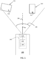
- FIG 1 shows a schematic top view of a vehicle 100 equipped with a vehicle sensor system 140.
- the vehicle moves in a direction with velocity vector v ego .
- the vehicle sensor system 140 comprises a vehicle sensor 110 and a control unit 120.
- An optional storage module 130 may also be comprised in the control unit 120. The storage module 130 will be discussed in more detail below.
- the control unit 120 is arranged to control operation of the vehicle sensor 110, and to obtain data from the vehicle sensor, such as detections or data points corresponding to objects 150, 160 in the vicinity of the vehicle 100.
- the vehicle sensor 110 may comprise a single sensor unit or a plurality of sensor units, potentially of different type and/or of different configuration.
- the vehicle sensor 110 may comprise any of a LIDAR sensor, a RADAR sensor, a camera sensor, or an ultrasound sensor.
- the vehicle sensor 110 may also comprise any of a TOF camera system, a structured light system, and a stereo vision system.
- the vehicle sensor 110 is arranged to generate a number of data points comprising coordinates in a relative coordinate system, i.e., relative to the location and orientation of the sensor.
- the coordinates may be Cartesian coordinates or they may be polar coordinates.
- the data points may also comprise additional information, such as light intensity values, colour data, signal strength values, frequency values, and measures of signal-to-noise ratio (SNR).
- SNR signal-to-noise ratio
- One or more time-stamps may also be associated with the detections.
- the time stamps may be assigned per data point or be common to a set of data points. A LIDAR system using a rolling shutter would most likely assign one-time stamp per data point, but it is also plausible to assign a single time stamp per scan or per data set, albeit with loss of accuracy.
- a data point in general, is a value or collection of values representing a configuration of an object or part of an object in an environment, such as in a vicinity of a vehicle.
- a data point may comprise a value indicating a range and an angle from the LIDAR sensor transceiver, or a set of coordinates describing a point in three-dimensional space.
- a data point may also comprise a velocity estimate obtained from a Doppler shift of a received waveform, and an angle or bearing obtained from an angle of arrival of a reflected sensor signal waveform.
- the velocity data may in some cases be quantized into moving or stationary, since some aspects of the methods disclosed herein comprises discarding data points related to moving objects.
- a sensor data point is at times referred to as a sample or as a detection. These terms are considered equivalent unless otherwise explicitly stated.
- the storage module 130 may store map data comprising information about a surrounding environment of the vehicle 100.
- New data points are produced more or less continuously by the sensor in cycles or scans.
- Most sensor systems generate detection data on a regular basis, with a cycle interval of T seconds.
- the interval T may correspond to a frame length of a radar signal, or to an image processing duration of a camera-based sensor, or to a scan period of a laser scanner.
- Detections may be stored by the storage module 130 and retrieved for processing as needed.
- At least one of the sensors may be arranged to sparsely sample the surrounding environment.
- to sparsely sample means that an object having an extension in space will only be represented by a single or a few data points each time update or scan. The data point or points representing an object may move over time (over cycles or scans) due to the effects of the sparse sampling. Sparse sampling will be discussed in more detail below in connection to Figures 4a and 4b .
- the vehicle sensor 110 is associated with a field of view 115, which may be a 360-degree field of view, or a more limited field of view as shown in Figure 1 .
- Two objects 150, 160 are located in the field of view 115.
- a first object 160 generates a data point marked by a star 161.
- a second object 150 generates a data point marked by a square 151.
- the first object 160 and the second object 150 may be tracked over time by a tracking algorithm which associates obtained data points with the different objects and continuously estimates, e.g., location and heading of the first and second object.
- a tracking algorithm which associates obtained data points with the different objects and continuously estimates, e.g., location and heading of the first and second object.
- Such tracking algorithms may robustly estimate the heading of a tracked object over time even if signal to noise ratio temporarily is reduced, or only a few detections are obtained in some cycles. Examples of such tracking algorithms include Kalman filters, extended Kalman filters, and Particle filters.
- the data points 151, 161 exhibit motion effects due to the sparse sampling, which means that the data points may move from scan to scan even though the objects 150, 160 are stationary objects. This motion may cause problems in higher layer algorithms such as tracking algorithms, which may need to spend significant processing power to classify the objects 150, 160 and associate detections 151, 161 to different objects.
- the techniques proposed herein aim at annotating data points or groups of data points as being associated with a stationary object if this is the case, even though the data points exhibit some motion. This way, the higher layer algorithms can more easily handle apparent motion effects.
- One of the main ideas behind the present disclosure is to define a feature or region as stable or stationary if its temporal variations correspond to a previously computed model of the region - and to provide this feature as external output from the vehicle sensor 110 or from the vehicle control unit 120.
- SLAM simultaneous localization and mapping
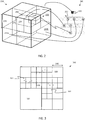
- Figure 2 illustrates an example hierarchical data structure 200 which can be used to represent a surrounding environment.
- the structure in Figure 2 is known as an octree.
- An octree is a hierarchical tree data structure in which each node or cell has eight children.
- Octrees are often used to partition a three-dimensional space by recursively subdividing it into eight cells 210a, 210b, 220, 230, or octants.
- the Octree can also be visualized by a tree structure 240, where a trunk node 250 has eight branches. Each branch leads to a node or cell 255 at a next level which again branches out into eight new branches.
- Each cell 210a, 210b, 220, 230 is associated with a cell range 270, 271, where the different cell ranges partition a space at different resolutions.
- a data point 260 is associated with a unique cell 220 at any given level of the octree based on the data point value and on the cell ranges at the different levels.
- a quadtree 300 schematically illustrated in Figure 3 , is a two-dimensional version of the octree. Like the octree, a quadtree divides a two-dimensional space into cells 310, 320, 330 having cell ranges 340 at different resolutions at different levels of the quadtree. Data points 301, 302 are again associated with unique cells at each level in the quadtree.
- hierarchical data structures such as the octree and quadtree data structures
- can be efficiently processed by discarding irrelevant cells e.g., by inserting null pointers at appropriate locations in a memory structure.
- cells not associated with any data points, or cells not associated with enough data points to determine a relevant cell feature such as a normal vector may be discarded to improve processing efficiency.
- cell 310 does not contain any data points, and could therefore potentially be ignored during further processing. It may also be advantageous to discard cells comprising data points associated with moving objects, since such data points may impact the end result, according to some aspects an end transformation, negatively.
- Hierarchical data structures include VDB trees, i.e., Volumetric Dynamic grid B-trees, and B+trees.
- VDB trees i.e., Volumetric Dynamic grid B-trees, and B+trees.
- the disclosed techniques are particularly suitable for use with Octrees and similar data structures but are not dependent on any particular type of data structure. Rather, the techniques disclosed herein are applicable together with a wide range of different data structures.
- the techniques disclosed herein can be used together with an octree-representation of the world model.
- the octree subdivides the world into cells of different sizes.
- NDT Normal Distribution Transform
- the covariance of each cell will represent the local distribution of the 3D world model. If the distribution resembles a plane, any new measurement will be considered 'stable' if its distance to the plane is low. If the distribution resembles a sphere, a new measurement will be considered 'stable' if the new point is statistically likely to be a part of the distribution.
- the subdivision of the octree into scale levels makes it possible to find regions that are stable on a large-scale level, but unstable on a smaller scale level, which is an advantage associated with the proposed techniques. A new measurement can therefore both be stable and unstable but on different levels.
- Each local region in the data structure comprises a statistical representation of the data points corresponding to the particular region.
- the cells in the octree may comprise information about a centroid value and a covariance matrix. These statistical measures can be used to determine of the data points in a given region corresponds to a planar structure of to a cuboid structure, or perhaps a spherical structure. Given such local statistical models, a new data point can be compared to the local statistical model to which it corresponds.
- a new data point may be obtained and associated to cell 210a.
- the previous data points associated to this cell may exhibit a statistical distribution with a variance indicating that the data points all lie on or at least close to a planar structure.
- the new data point is close to this planar structure, then it can be annotated as stable or stationary and optionally also as belonging to the planar structure.
- the new data point is not in agreement with the local statistical distribution, then the data point may not correspond to the planar structure and should therefore not be labelled as stable or stationary.
- oscillating centroids can be annotated as 'stable' if they move according to the model of the underlying surface
- Figure 4a-4c illustrate examples showing the effects of sparse sampling of an environment, and the application of the proposed annotation techniques.
- Figure 4a illustrates a scenario where a vehicle 100 obtains a new data point 420 corresponding to a patch of road surface 410.
- the patch of road surface is relatively flat, which means that the statistical distribution of data points obtained from this local area can be expected to show a statistical distribution in agreement with a planar structure.
- Figure 4b shows a scenario where the vehicle 100 has travelled some distance towards the flat patch of road surface 410.
- the vehicle 100 obtains a new data point 440 which agrees with the local statistical model comprised in the static model of the environment.
- This newly obtained data point 440 is therefore annotated as stationary even though it differs from the previously obtained data point 420.
- the vehicle 100 may also obtain a data point 460 which is located some distance away from the patch of road surface.
- This newly obtained data point 460 is not in agreement with the local statistical model, and should therefore not be annotated as stable, at least until more information is available.
- the newly obtained data point 460 has been generated by some other stationary object that is just coming into view of the sensor and which has not yet made an impact on the static model of the environment which the vehicle is maintaining.
- FIG. 5 is a flow chart showing methods that summarize the discussions above.
- the method comprises obtaining S1 a set of data points associated with an environment sampled by a vehicle sensor 110.
- the obtaining may, e.g., be mostly based on sensing data points by on-board vehicle sensors. However, the obtaining may also optionally comprise downloading data from a remote server or receiving data from other vehicles.
- the method also comprises determining S2 a static model 200, 300 of the environment based on the set of data points, wherein the static model of the environment comprises a collection of local statistical models.
- the static model of the environment may, e.g., be based on an Octree representation as discussed in connection to Figures 2 and 3 above.
- Each cell at each hierarchical level is then associated with a statistical model, which represents a local statistical model.
- the method further comprises obtaining S3 a new data point associated with the environment.
- the new data point may, e.g., be obtained as a recent sample from a vehicle sensor, or it may be obtained as a sensor sample sensed by some other vehicle or downloaded from a remote server.
- the method comprises associating S4 the new data point to a corresponding local statistical model comprised in the static model of the environment.
- the associating may comprise determining a distance metric between the new data point and the local statistical model in the corresponding region of the static model of the environment.
- One such distance metric is the probability of sensing the new data point given the local statistical model of data points in the region.
- Another such distance metric is a Gaussian distance metric given as; exp ⁇ 1 2 x ⁇ ⁇ T W ⁇ 1 x ⁇ ⁇ , where x is the data point, ⁇ is the mean of an assumed local statistical distribution, and W is an assumed covariance matrix of the assumed local statistical distribution.
- a local statistical model may be based on a Normal Distribution Transform, NDT, over data points comprised in the associated local area, or Octree cell if that representation is used.
- NDT Normal Distribution Transform
- a covariance of each local area then represents a local distribution of the static model of the environment.
- the local area may, e.g., be a cell in an Octree structure, in which case the NDT is applied on data points associated with the cell.
- the annotating is based on a statistical distance metric from the new data point to the corresponding local statistical model.
- the collection of local statistical models describes local distributions of data points in the environment.
- the method also comprises annotating S5 the new data point as a stable data point in case the new data point agrees with the corresponding local statistical model.
- the 'agreement' can be implemented in many different ways as is realized by the skilled person. For instance, agreement may be taken to mean that the above-mentioned distance metric should be below some predetermined threshold in order to indicate agreement and to not indicate agreement otherwise.
- the data points comprise light detection and ranging, LIDAR sensor data S11 and/or radio detection and ranging, RADAR, sensor data S12.
- each cell of the octree, quadtree or octree map is associated with a local statistical model.
- the local distribution is selected from any of; a plane, a sphere, or a cuboid.
- the method also comprises extending S6 the static model of the environment based on the new data point in case no corresponding local statistical model is available.
- a new data point may correspond to a region in the static model of the environment in which no previous data points have been obtained, i.e., the region is new ground. In this case, it may be reasonable to start a new local model based on the new data point.
- This new data point may optionally be annotated as unstable in case no other data is available indicating that the data point is associated with a dynamic object or the like.
- the method also comprises updating S7 the static model of the environment based on the new data point in case the new data point does not agree with the corresponding local statistical model.
- the new data point is the first data point associated with some static structure that is just coming into view by the sensor 110. In this case it makes sense to update the local statistical model to eventually allow more data points from the new structure to be annotated as stable or stationary. According to some aspects, this is done when the updated model has been determined to have a higher certainty than the model before updating. This can according to some aspects be due to the fact that more measurements fit the updated model, and/or that the model before updating has expired time-wise.
- the method also comprises excluding S8 the new data point from the static model of the environment in case the new data point is detected as corresponding to a non-stationary object in the environment.
- Dynamic data points may be indicated by, e.g., Doppler data. These data points are necessarily not comprised in a static object.
- the method also comprises providing S9 the annotated data points as an output from a control unit 120.
- objects that are moving in a scene may also have 'stable' and 'unstable' regions. Then, the annotation may be done with respect to the local coordinate-system of the vehicle instead of the static world map.
- FIG. 6 schematically illustrates, in terms of a number of functional units, the components of a control unit 120 according to an embodiment of the above discussions.
- Processing circuitry 610 is provided using any combination of one or more of a suitable central processing unit CPU, multiprocessor, microcontroller, digital signal processor DSP, etc., capable of executing software instructions stored in a computer program product, e.g. in the form of a storage medium 630.
- the processing circuitry 610 may further be provided as at least one application specific integrated circuit ASIC, or field programmable gate array FPGA.
- the processing circuitry 610 is configured to cause the control unit 120 to perform a set of operations, or steps.
- the storage medium 630 may store the set of operations
- the processing circuitry 610 may be configured to retrieve the set of operations from the storage medium 630 to cause the control unit 120 to perform the set of operations.
- the set of operations may be provided as a set of executable instructions.
- the processing circuitry 610 is thereby arranged to execute methods as herein disclosed.
- the storage medium 630 may also comprise persistent storage, which, for example, can be any single one or combination of magnetic memory, optical memory, solid state memory or even remotely mounted memory.
- the control unit 120 may further comprise a communications interface 620 for communications with at least one external device, such as a vehicle sensor 110.
- the communication interface 620 may comprise one or more transmitters and receivers, comprising analogue and digital components and a suitable number of ports for wireline or wireless communication.
- the processing circuitry 610 controls the general operation of the control unit 120 e.g. by sending data and control signals to the communication interface 620 and the storage medium 630, by receiving data and reports from the communication interface 620, and by retrieving data and instructions from the storage medium 630.
- Other components, as well as the related functionality, of the control unit 120 are omitted in order not to obscure the concepts presented herein.
- the control unit 120 is configured to annotate data points 151, 161 in a data set. To achieve this, the control unit 120 is adapted to obtain a set of data points associated with an environment sampled by a vehicle sensor 110 and to determine a static model 200, 300 of the environment based on the set of data points, wherein the static model of the environment comprises a collection of local statistical models. The control unit 120 is further adapted to obtain a new data point associated with the environment, to associate the new data point to a corresponding local statistical model comprised in the static model of the environment, and to annotate the new data point as a stable data point in case the new data point agrees with the corresponding local statistical model.
- Figure 7 shows a computer program product 700 comprising computer executable instructions 710.
- the computer executable instructions may, e.g., be executed by a control unit 120 as described above to perform the herein disclosed methods.
Landscapes
- Engineering & Computer Science (AREA)
- Physics & Mathematics (AREA)
- General Physics & Mathematics (AREA)
- Theoretical Computer Science (AREA)
- Radar, Positioning & Navigation (AREA)
- Remote Sensing (AREA)
- Multimedia (AREA)
- Databases & Information Systems (AREA)
- Electromagnetism (AREA)
- Computer Networks & Wireless Communication (AREA)
- Computer Vision & Pattern Recognition (AREA)
- Software Systems (AREA)
- Evolutionary Computation (AREA)
- General Health & Medical Sciences (AREA)
- Medical Informatics (AREA)
- Computing Systems (AREA)
- Artificial Intelligence (AREA)
- Health & Medical Sciences (AREA)
- Life Sciences & Earth Sciences (AREA)
- Bioinformatics & Cheminformatics (AREA)
- Bioinformatics & Computational Biology (AREA)
- Evolutionary Biology (AREA)
- Probability & Statistics with Applications (AREA)
- Traffic Control Systems (AREA)
- Optical Radar Systems And Details Thereof (AREA)
Abstract
Description
- The present disclosure relates to methods and devices for annotating data points in a data set. The disclosed techniques are applicable, e.g., to sparsely sampled Light Detection and Ranging (LIDAR) data in vehicular applications, and for scan matching or pose registration in general.
- Many different types of sensors sample their surrounding environment sparsely, which means that an object in the environment is only represented by a single or by a few data points that are output from the sensor to represent the entire object. A stretch of road surface may for instance only be seen as a single data point in a cloud of data points, not as a continuous surface. As the sensor moves in relation to the object, the sampled data points associated with the object are likely to change, causing the object to appear as if it is moving even though it is a stationary object. LIDAR sensors often sample the surrounding environment sparsely.
- Higher layer systems and control algorithms may have problems interpreting and classifying such sparsely sampled data. For instance, the higher layer algorithms may require significant processing resources in order to classify samples as belonging to a stationary object vs belonging to a non-stationary object due to the apparent motion effects from the sparse sampling.
- It is an object of the present disclosure to present methods and devices for annotating a sparsely sampled data set, whereby samples or groups of samples are annotated as stable or stationary despite presence of apparent motion effects due to sparse sampling.
- This object is achieved by a method for annotating data points in a data set, where the method comprises obtaining a set of data points associated with an environment sampled by a vehicle sensor and determining a static model of the environment based on the set of data points, wherein the static model of the environment comprises a collection of local statistical models. The method further comprises obtaining a new data point associated with the environment, associating the new data point to a corresponding local statistical model comprised in the static model of the environment, and annotating the new data point as a stable data point in case the new data point agrees with the corresponding local statistical model.
- This means that samples or groups of samples can be annotated as stable or stationary despite possible presence of apparent motion effects due to sparse sampling. This helps in classifying the nature of movements with respect to previously accumulated data. A label may be a part of sensor output, and can therefore be used as a temporal feature for subsequent sensor fusion systems. A static object, such as a tree, can be labelled as 'stable' on the macro scale, even though it is considered 'unstable' on a smaller scale.
- According to some aspects, the data points comprise light detection and ranging, LIDAR sensor data and/or radio detection and ranging, RADAR, sensor data.
- The present disclosure is thus applicable for data from a broad variety of vehicle sensors.
- According to some aspects, the collection of local statistical models describes local distributions of data points in the environment.
- This means that a new data point can be annotated as a stable or unstable data point in dependence of if the new data point is considered close to, or resembling, a current distribution.
- According to some aspects, a local statistical model comprises a Normal Distribution Transform (NDT) over data points comprised in the associated local area, wherein a covariance of each local area represents a local distribution of the static model of the environment.
- A well-known transform, can thus be used.
- According to some aspects, the annotating is based on a statistical distance metric from the new data point to the corresponding local statistical model.
- This means that a new data point can be annotated as a stable or unstable data point in dependence of if the new data point is considered close to a current distribution.
- According to some aspects, the static model of the environment comprises an octree, a quadtree, or an octree map representation.
- Well-known and effective representations can thus be used for the present disclosure.
- According to some aspects, each cell of the octree, quadtree or octree map is associated with a local statistical model.
- According to some aspects, the local distribution is selected from any of; a plane, a sphere, or a cuboid.
- According to some aspects, the method comprises extending the static model of the environment based on the new data point in case no corresponding local statistical model is available.
- In this way, a new data point that for example corresponds to a region in the static model of the environment in which no previous data points have been obtained, i.e., the region is new ground, can be handled. A new local model based can for example be started on the new data point. This new data point may optionally be annotated as unstable in case no other data is available indicating that the data point is associated with a dynamic object or the like.
- According to some aspects, the method comprises updating the static model of the environment based on the new data point in case the new data point does not agree with the corresponding local statistical model.
- In this way, a new data point that is the first data point associated with some static structure that is just coming into view by a vehicle sensor can be handled.
- According to some aspects, the method comprises excluding the new data point from the static model of the environment in case the new data point is detected as corresponding to a non-stationary object in the environment.
- In this manner, a new data point can be annotated as unstable.
- This object is also achieved by means of a control unit and a vehicle which are associated with the above advantages.
- The present disclosure will now be described in detail with reference to the appended drawings, where:
-
Figure 1 shows a schematic top view of a vehicle with a sensor system; -
Figures 2-3 illustrate examples of hierarchical data structures; -
Figure 4a-4c illustrate effects of sparse sampling; -
Figure 5 is a flow chart illustrating methods; -
Figure 6 schematically illustrates a control unit; and -
Figure 7 shows an example computer program product. - Aspects of the present disclosure will now be described more fully hereinafter with reference to the accompanying drawings. The different devices, systems, computer programs and methods disclosed herein can, however, be realized in many different forms and should not be construed as being limited to the aspects set forth herein. Like numbers in the drawings refer to like elements throughout.
- The terminology used herein is for describing aspects of the disclosure only and is not intended to limit the invention. As used herein, the singular forms "a", "an" and "the" are intended to include the plural forms as well, unless the context clearly indicates otherwise.
-
Figure 1 shows a schematic top view of avehicle 100 equipped with avehicle sensor system 140. The vehicle moves in a direction with velocity vector vego. Thevehicle sensor system 140 comprises avehicle sensor 110 and acontrol unit 120. Anoptional storage module 130 may also be comprised in thecontrol unit 120. Thestorage module 130 will be discussed in more detail below. - The
control unit 120 is arranged to control operation of thevehicle sensor 110, and to obtain data from the vehicle sensor, such as detections or data points corresponding toobjects vehicle 100. - The
vehicle sensor 110 may comprise a single sensor unit or a plurality of sensor units, potentially of different type and/or of different configuration. For instance, thevehicle sensor 110 may comprise any of a LIDAR sensor, a RADAR sensor, a camera sensor, or an ultrasound sensor. Thevehicle sensor 110 may also comprise any of a TOF camera system, a structured light system, and a stereo vision system. - The
vehicle sensor 110 is arranged to generate a number of data points comprising coordinates in a relative coordinate system, i.e., relative to the location and orientation of the sensor. The coordinates may be Cartesian coordinates or they may be polar coordinates. - The data points may also comprise additional information, such as light intensity values, colour data, signal strength values, frequency values, and measures of signal-to-noise ratio (SNR). One or more time-stamps may also be associated with the detections. The time stamps may be assigned per data point or be common to a set of data points. A LIDAR system using a rolling shutter would most likely assign one-time stamp per data point, but it is also plausible to assign a single time stamp per scan or per data set, albeit with loss of accuracy.
- A data point, in general, is a value or collection of values representing a configuration of an object or part of an object in an environment, such as in a vicinity of a vehicle. For instance, in case of a LIDAR sensor, a data point may comprise a value indicating a range and an angle from the LIDAR sensor transceiver, or a set of coordinates describing a point in three-dimensional space. A data point may also comprise a velocity estimate obtained from a Doppler shift of a received waveform, and an angle or bearing obtained from an angle of arrival of a reflected sensor signal waveform. The velocity data may in some cases be quantized into moving or stationary, since some aspects of the methods disclosed herein comprises discarding data points related to moving objects.
- Herein, a sensor data point is at times referred to as a sample or as a detection. These terms are considered equivalent unless otherwise explicitly stated.
- The
storage module 130 may store map data comprising information about a surrounding environment of thevehicle 100. - New data points are produced more or less continuously by the sensor in cycles or scans. Most sensor systems generate detection data on a regular basis, with a cycle interval of T seconds. For instance, the interval T may correspond to a frame length of a radar signal, or to an image processing duration of a camera-based sensor, or to a scan period of a laser scanner. Detections may be stored by the
storage module 130 and retrieved for processing as needed. - At least one of the sensors may be arranged to sparsely sample the surrounding environment. Herein, to sparsely sample means that an object having an extension in space will only be represented by a single or a few data points each time update or scan. The data point or points representing an object may move over time (over cycles or scans) due to the effects of the sparse sampling. Sparse sampling will be discussed in more detail below in connection to
Figures 4a and 4b . - The
vehicle sensor 110 is associated with a field ofview 115, which may be a 360-degree field of view, or a more limited field of view as shown inFigure 1 . Twoobjects view 115. Afirst object 160 generates a data point marked by astar 161. Asecond object 150 generates a data point marked by a square 151. - The
first object 160 and thesecond object 150 may be tracked over time by a tracking algorithm which associates obtained data points with the different objects and continuously estimates, e.g., location and heading of the first and second object. Such tracking algorithms may robustly estimate the heading of a tracked object over time even if signal to noise ratio temporarily is reduced, or only a few detections are obtained in some cycles. Examples of such tracking algorithms include Kalman filters, extended Kalman filters, and Particle filters. - The data points 151, 161 exhibit motion effects due to the sparse sampling, which means that the data points may move from scan to scan even though the
objects objects associate detections - To aid higher layer algorithms, the techniques proposed herein aim at annotating data points or groups of data points as being associated with a stationary object if this is the case, even though the data points exhibit some motion. This way, the higher layer algorithms can more easily handle apparent motion effects. One of the main ideas behind the present disclosure is to define a feature or region as stable or stationary if its temporal variations correspond to a previously computed model of the region - and to provide this feature as external output from the
vehicle sensor 110 or from thevehicle control unit 120. - In order to make use of acquired data points, new data sets must often first be aligned with a reference coordinate system or be registered relative to another data set. Such scan matching plays a crucial role in, e.g., simultaneous localization and mapping (SLAM) applications.
-
Figure 2 illustrates an examplehierarchical data structure 200 which can be used to represent a surrounding environment. The structure inFigure 2 is known as an octree. An octree is a hierarchical tree data structure in which each node or cell has eight children. Octrees are often used to partition a three-dimensional space by recursively subdividing it into eightcells tree structure 240, where atrunk node 250 has eight branches. Each branch leads to a node orcell 255 at a next level which again branches out into eight new branches. - Each
cell cell range data point 260 is associated with aunique cell 220 at any given level of the octree based on the data point value and on the cell ranges at the different levels. Aquadtree 300, schematically illustrated inFigure 3 , is a two-dimensional version of the octree. Like the octree, a quadtree divides a two-dimensional space intocells - It is appreciated that hierarchical data structures, such as the octree and quadtree data structures, can be efficiently processed by discarding irrelevant cells, e.g., by inserting null pointers at appropriate locations in a memory structure. For instance, cells not associated with any data points, or cells not associated with enough data points to determine a relevant cell feature such as a normal vector, may be discarded to improve processing efficiency. In the example of
Figure 3 ,cell 310 does not contain any data points, and could therefore potentially be ignored during further processing. It may also be advantageous to discard cells comprising data points associated with moving objects, since such data points may impact the end result, according to some aspects an end transformation, negatively. - Other examples of hierarchical data structures include VDB trees, i.e., Volumetric Dynamic grid B-trees, and B+trees. The disclosed techniques are particularly suitable for use with Octrees and similar data structures but are not dependent on any particular type of data structure. Rather, the techniques disclosed herein are applicable together with a wide range of different data structures.
- The techniques disclosed herein can be used together with an octree-representation of the world model. The octree subdivides the world into cells of different sizes. By, for example, computing a Normal Distribution Transform (NDT) over the octree, the covariance of each cell will represent the local distribution of the 3D world model. If the distribution resembles a plane, any new measurement will be considered 'stable' if its distance to the plane is low. If the distribution resembles a sphere, a new measurement will be considered 'stable' if the new point is statistically likely to be a part of the distribution. The subdivision of the octree into scale levels makes it possible to find regions that are stable on a large-scale level, but unstable on a smaller scale level, which is an advantage associated with the proposed techniques. A new measurement can therefore both be stable and unstable but on different levels.
- Each local region in the data structure comprises a statistical representation of the data points corresponding to the particular region. For example, the cells in the octree may comprise information about a centroid value and a covariance matrix. These statistical measures can be used to determine of the data points in a given region corresponds to a planar structure of to a cuboid structure, or perhaps a spherical structure. Given such local statistical models, a new data point can be compared to the local statistical model to which it corresponds.
- For instance, a new data point may be obtained and associated to
cell 210a. The previous data points associated to this cell may exhibit a statistical distribution with a variance indicating that the data points all lie on or at least close to a planar structure. Now, if also the new data point is close to this planar structure, then it can be annotated as stable or stationary and optionally also as belonging to the planar structure. However, if the new data point is not in agreement with the local statistical distribution, then the data point may not correspond to the planar structure and should therefore not be labelled as stable or stationary. - According to some aspects, oscillating centroids can be annotated as 'stable' if they move according to the model of the underlying surface
-
Figure 4a-4c illustrate examples showing the effects of sparse sampling of an environment, and the application of the proposed annotation techniques.Figure 4a illustrates a scenario where avehicle 100 obtains anew data point 420 corresponding to a patch ofroad surface 410. The patch of road surface is relatively flat, which means that the statistical distribution of data points obtained from this local area can be expected to show a statistical distribution in agreement with a planar structure. -
Figure 4b shows a scenario where thevehicle 100 has travelled some distance towards the flat patch ofroad surface 410. Thevehicle 100 obtains anew data point 440 which agrees with the local statistical model comprised in the static model of the environment. This newly obtaineddata point 440 is therefore annotated as stationary even though it differs from the previously obtaineddata point 420. - However, as shown in
Figure 4c , thevehicle 100 may also obtain adata point 460 which is located some distance away from the patch of road surface. This newly obtaineddata point 460 is not in agreement with the local statistical model, and should therefore not be annotated as stable, at least until more information is available. Perhaps the newly obtaineddata point 460 has been generated by some other stationary object that is just coming into view of the sensor and which has not yet made an impact on the static model of the environment which the vehicle is maintaining. -
Figure 5 is a flow chart showing methods that summarize the discussions above. There is illustrated a method for annotatingdata points vehicle sensor 110. The obtaining may, e.g., be mostly based on sensing data points by on-board vehicle sensors. However, the obtaining may also optionally comprise downloading data from a remote server or receiving data from other vehicles. The method also comprises determining S2 astatic model Figures 2 and 3 above. Each cell at each hierarchical level is then associated with a statistical model, which represents a local statistical model. - The method further comprises obtaining S3 a new data point associated with the environment. The new data point may, e.g., be obtained as a recent sample from a vehicle sensor, or it may be obtained as a sensor sample sensed by some other vehicle or downloaded from a remote server.
- The method comprises associating S4 the new data point to a corresponding local statistical model comprised in the static model of the environment. For example, the associating may comprise determining a distance metric between the new data point and the local statistical model in the corresponding region of the static model of the environment. One such distance metric is the probability of sensing the new data point given the local statistical model of data points in the region. Another such distance metric is a Gaussian distance metric given as;

- As another example, a local statistical model may be based on a Normal Distribution Transform, NDT, over data points comprised in the associated local area, or Octree cell if that representation is used. A covariance of each local area then represents a local distribution of the static model of the environment. The local area may, e.g., be a cell in an Octree structure, in which case the NDT is applied on data points associated with the cell.
- In other words, according to some aspects, the annotating is based on a statistical distance metric from the new data point to the corresponding local statistical model. According to other aspects, the collection of local statistical models describes local distributions of data points in the environment.
- The method also comprises annotating S5 the new data point as a stable data point in case the new data point agrees with the corresponding local statistical model. The 'agreement' can be implemented in many different ways as is realized by the skilled person. For instance, agreement may be taken to mean that the above-mentioned distance metric should be below some predetermined threshold in order to indicate agreement and to not indicate agreement otherwise.
- According to aspects, the data points comprise light detection and ranging, LIDAR sensor data S11 and/or radio detection and ranging, RADAR, sensor data S12.
- According to aspects, each cell of the octree, quadtree or octree map is associated with a local statistical model.
- According to aspects, the local distribution is selected from any of; a plane, a sphere, or a cuboid.
- According to aspects, the method also comprises extending S6 the static model of the environment based on the new data point in case no corresponding local statistical model is available. For instance, a new data point may correspond to a region in the static model of the environment in which no previous data points have been obtained, i.e., the region is new ground. In this case, it may be reasonable to start a new local model based on the new data point. This new data point may optionally be annotated as unstable in case no other data is available indicating that the data point is associated with a dynamic object or the like.
- According to aspects, the method also comprises updating S7 the static model of the environment based on the new data point in case the new data point does not agree with the corresponding local statistical model. Perhaps the new data point is the first data point associated with some static structure that is just coming into view by the
sensor 110. In this case it makes sense to update the local statistical model to eventually allow more data points from the new structure to be annotated as stable or stationary. According to some aspects, this is done when the updated model has been determined to have a higher certainty than the model before updating. This can according to some aspects be due to the fact that more measurements fit the updated model, and/or that the model before updating has expired time-wise. - According to aspects, the method also comprises excluding S8 the new data point from the static model of the environment in case the new data point is detected as corresponding to a non-stationary object in the environment. Dynamic data points may be indicated by, e.g., Doppler data. These data points are necessarily not comprised in a static object.
- According to aspects, the method also comprises providing S9 the annotated data points as an output from a
control unit 120. - It is appreciated that objects that are moving in a scene (e.g. other vehicles etc.) may also have 'stable' and 'unstable' regions. Then, the annotation may be done with respect to the local coordinate-system of the vehicle instead of the static world map.
- The methods and techniques discussed above can be realized in various forms of hardware.
Figure 6 schematically illustrates, in terms of a number of functional units, the components of acontrol unit 120 according to an embodiment of the above discussions.Processing circuitry 610 is provided using any combination of one or more of a suitable central processing unit CPU, multiprocessor, microcontroller, digital signal processor DSP, etc., capable of executing software instructions stored in a computer program product, e.g. in the form of astorage medium 630. Theprocessing circuitry 610 may further be provided as at least one application specific integrated circuit ASIC, or field programmable gate array FPGA. - Particularly, the
processing circuitry 610 is configured to cause thecontrol unit 120 to perform a set of operations, or steps. For example, thestorage medium 630 may store the set of operations, and theprocessing circuitry 610 may be configured to retrieve the set of operations from thestorage medium 630 to cause thecontrol unit 120 to perform the set of operations. The set of operations may be provided as a set of executable instructions. Thus, theprocessing circuitry 610 is thereby arranged to execute methods as herein disclosed. - The
storage medium 630 may also comprise persistent storage, which, for example, can be any single one or combination of magnetic memory, optical memory, solid state memory or even remotely mounted memory. - The
control unit 120 may further comprise acommunications interface 620 for communications with at least one external device, such as avehicle sensor 110. As such, thecommunication interface 620 may comprise one or more transmitters and receivers, comprising analogue and digital components and a suitable number of ports for wireline or wireless communication. - The
processing circuitry 610 controls the general operation of thecontrol unit 120 e.g. by sending data and control signals to thecommunication interface 620 and thestorage medium 630, by receiving data and reports from thecommunication interface 620, and by retrieving data and instructions from thestorage medium 630. Other components, as well as the related functionality, of thecontrol unit 120 are omitted in order not to obscure the concepts presented herein. - The
control unit 120 is configured to annotatedata points control unit 120 is adapted to obtain a set of data points associated with an environment sampled by avehicle sensor 110 and to determine astatic model control unit 120 is further adapted to obtain a new data point associated with the environment, to associate the new data point to a corresponding local statistical model comprised in the static model of the environment, and to annotate the new data point as a stable data point in case the new data point agrees with the corresponding local statistical model. -
Figure 7 shows acomputer program product 700 comprising computerexecutable instructions 710. The computer executable instructions may, e.g., be executed by acontrol unit 120 as described above to perform the herein disclosed methods.
Claims (14)
obtaining (S1) a set of data points associated with an environment sampled by a vehicle sensor (110);
determining (S2) a static model (200, 300) of the environment based on the set of data points, wherein the static model of the environment comprises a collection of local statistical models;
obtaining (S3) a new data point associated with the environment;
associating (S4) the new data point to a corresponding local statistical model comprised in the static model of the environment;
annotating (S5) the new data point as a stable data point in case the new data point agrees with the corresponding local statistical model.
Priority Applications (1)
| Application Number | Priority Date | Filing Date | Title |
|---|---|---|---|
| EP19202196.2A EP3805987B1 (en) | 2019-10-09 | 2019-10-09 | Annotating a sparsely sampled data set |
Applications Claiming Priority (1)
| Application Number | Priority Date | Filing Date | Title |
|---|---|---|---|
| EP19202196.2A EP3805987B1 (en) | 2019-10-09 | 2019-10-09 | Annotating a sparsely sampled data set |
Publications (2)
| Publication Number | Publication Date |
|---|---|
| EP3805987A1 true EP3805987A1 (en) | 2021-04-14 |
| EP3805987B1 EP3805987B1 (en) | 2024-10-02 |
Family
ID=68242456
Family Applications (1)
| Application Number | Title | Priority Date | Filing Date |
|---|---|---|---|
| EP19202196.2A Active EP3805987B1 (en) | 2019-10-09 | 2019-10-09 | Annotating a sparsely sampled data set |
Country Status (1)
| Country | Link |
|---|---|
| EP (1) | EP3805987B1 (en) |
Cited By (1)
| Publication number | Priority date | Publication date | Assignee | Title |
|---|---|---|---|---|
| CN114280626A (en) * | 2021-12-17 | 2022-04-05 | 成都朴为科技有限公司 | Laser radar SLAM method and system based on local structure information expansion |
-
2019
- 2019-10-09 EP EP19202196.2A patent/EP3805987B1/en active Active
Non-Patent Citations (2)
| Title |
|---|
| C. STAUFFER ET AL: "Adaptive background mixture models for real-time tracking", PROCEEDINGS OF THE 1999 IEEE COMPUTER SOCIETY CONFERENCE ON COMPUTER VISION AND PATTERN RECOGNITION, JUNE 23-25, 1999; FORT COLLINS, COLORADO, 1 January 1999 (1999-01-01), US, pages 246 - 252, XP055549596, ISBN: 978-0-7695-0149-9, DOI: 10.1109/CVPR.1999.784637 * |
| RALF KÄSTNER ET AL: "A Bayesian Approach to Learning 3D Representations of Dynamic Environments", 12TH INTERNATIONAL SYMPOSIUM ON EXPERIMENTAL ROBOTICS (ISER 2010), 21 December 2010 (2010-12-21), XP055684775, DOI: 10.3929/ethz-a-010034936 * |
Cited By (1)
| Publication number | Priority date | Publication date | Assignee | Title |
|---|---|---|---|---|
| CN114280626A (en) * | 2021-12-17 | 2022-04-05 | 成都朴为科技有限公司 | Laser radar SLAM method and system based on local structure information expansion |
Also Published As
| Publication number | Publication date |
|---|---|
| EP3805987B1 (en) | 2024-10-02 |
Similar Documents
| Publication | Publication Date | Title |
|---|---|---|
| CN108319655B (en) | Method and device for generating grid map | |
| CN109521756B (en) | Method and device for generating obstacle motion information for unmanned vehicles | |
| Vandapel et al. | Natural terrain classification using 3-d ladar data | |
| EP3252657B1 (en) | Information processing device and information processing method | |
| CN112379674B (en) | Automatic driving equipment and system | |
| CN112379393B (en) | Train collision early warning method and device | |
| CN117808689A (en) | Depth completion method based on fusion of millimeter wave radar and camera | |
| CN111045000A (en) | Monitoring system and method | |
| JP6322564B2 (en) | Point cloud analysis processing apparatus, method, and program | |
| EP3798665A1 (en) | Method and system for aligning radar detection data | |
| CN112781599B (en) | Method for determining the position of a vehicle | |
| CN114384486B (en) | Data processing method and device | |
| CN115147333A (en) | Target detection method and device | |
| CN119705368B (en) | Collision warning method, device and medium based on fusion sensor | |
| CN116203577A (en) | Target detection method and device based on multi-signal fusion | |
| CN114119465B (en) | Point cloud data processing method and device | |
| CN111856499A (en) | Map construction method and device based on laser radar | |
| JP2024014785A (en) | Target object prediction method, computer equipment and storage medium | |
| JP4984659B2 (en) | Own vehicle position estimation device | |
| CN120044516A (en) | Foundation unmanned aerial vehicle positioning scheme based on high-frequency fusion of event camera and millimeter wave radar | |
| WO2022162616A1 (en) | Systems and methods for combining multiple depth maps | |
| EP3805987B1 (en) | Annotating a sparsely sampled data set | |
| CN116594009A (en) | A detection system and method for detecting objects in an observation environment | |
| CN119156548A (en) | Point cloud evaluation method and device | |
| CN116888502A (en) | Object position detection device and method |
Legal Events
| Date | Code | Title | Description |
|---|---|---|---|
| PUAI | Public reference made under article 153(3) epc to a published international application that has entered the european phase |
Free format text: ORIGINAL CODE: 0009012 |
|
| STAA | Information on the status of an ep patent application or granted ep patent |
Free format text: STATUS: THE APPLICATION HAS BEEN PUBLISHED |
|
| AK | Designated contracting states |
Kind code of ref document: A1 Designated state(s): AL AT BE BG CH CY CZ DE DK EE ES FI FR GB GR HR HU IE IS IT LI LT LU LV MC MK MT NL NO PL PT RO RS SE SI SK SM TR |
|
| AX | Request for extension of the european patent |
Extension state: BA ME |
|
| STAA | Information on the status of an ep patent application or granted ep patent |
Free format text: STATUS: REQUEST FOR EXAMINATION WAS MADE |
|
| 17P | Request for examination filed |
Effective date: 20210902 |
|
| RBV | Designated contracting states (corrected) |
Designated state(s): AL AT BE BG CH CY CZ DE DK EE ES FI FR GB GR HR HU IE IS IT LI LT LU LV MC MK MT NL NO PL PT RO RS SE SI SK SM TR |
|
| STAA | Information on the status of an ep patent application or granted ep patent |
Free format text: STATUS: EXAMINATION IS IN PROGRESS |
|
| 17Q | First examination report despatched |
Effective date: 20230206 |
|
| REG | Reference to a national code |
Ref country code: DE Ref legal event code: R079 Ref document number: 602019059675 Country of ref document: DE Free format text: PREVIOUS MAIN CLASS: G06K0009620000 Ipc: G06V0020560000 |
|
| RAP3 | Party data changed (applicant data changed or rights of an application transferred) |
Owner name: MAGNA ELECTRONICS SWEDEN AB |
|
| RIC1 | Information provided on ipc code assigned before grant |
Ipc: G01S 17/931 20200101ALI20240321BHEP Ipc: G01S 13/931 20200101ALI20240321BHEP Ipc: G01S 7/41 20060101ALI20240321BHEP Ipc: G01S 13/86 20060101ALI20240321BHEP Ipc: G06V 10/52 20220101ALI20240321BHEP Ipc: G06V 10/46 20220101ALI20240321BHEP Ipc: G06V 10/774 20220101ALI20240321BHEP Ipc: G06V 20/56 20220101AFI20240321BHEP |
|
| GRAP | Despatch of communication of intention to grant a patent |
Free format text: ORIGINAL CODE: EPIDOSNIGR1 |
|
| STAA | Information on the status of an ep patent application or granted ep patent |
Free format text: STATUS: GRANT OF PATENT IS INTENDED |
|
| INTG | Intention to grant announced |
Effective date: 20240430 |
|
| RAP3 | Party data changed (applicant data changed or rights of an application transferred) |
Owner name: MAGNA ELECTRONICS SWEDEN AB |
|
| GRAS | Grant fee paid |
Free format text: ORIGINAL CODE: EPIDOSNIGR3 |
|
| GRAA | (expected) grant |
Free format text: ORIGINAL CODE: 0009210 |
|
| STAA | Information on the status of an ep patent application or granted ep patent |
Free format text: STATUS: THE PATENT HAS BEEN GRANTED |
|
| AK | Designated contracting states |
Kind code of ref document: B1 Designated state(s): AL AT BE BG CH CY CZ DE DK EE ES FI FR GB GR HR HU IE IS IT LI LT LU LV MC MK MT NL NO PL PT RO RS SE SI SK SM TR |
|
| REG | Reference to a national code |
Ref country code: GB Ref legal event code: FG4D |
|
| REG | Reference to a national code |
Ref country code: CH Ref legal event code: EP |
|
| REG | Reference to a national code |
Ref country code: IE Ref legal event code: FG4D |
|
| REG | Reference to a national code |
Ref country code: DE Ref legal event code: R096 Ref document number: 602019059675 Country of ref document: DE |
|
| REG | Reference to a national code |
Ref country code: SE Ref legal event code: TRGR |
|
| REG | Reference to a national code |
Ref country code: LT Ref legal event code: MG9D |
|
| REG | Reference to a national code |
Ref country code: NL Ref legal event code: MP Effective date: 20241002 |
|
| REG | Reference to a national code |
Ref country code: AT Ref legal event code: MK05 Ref document number: 1729034 Country of ref document: AT Kind code of ref document: T Effective date: 20241002 |
|
| PG25 | Lapsed in a contracting state [announced via postgrant information from national office to epo] |
Ref country code: NL Free format text: LAPSE BECAUSE OF FAILURE TO SUBMIT A TRANSLATION OF THE DESCRIPTION OR TO PAY THE FEE WITHIN THE PRESCRIBED TIME-LIMIT Effective date: 20241002 |
|
| PG25 | Lapsed in a contracting state [announced via postgrant information from national office to epo] |
Ref country code: NL Free format text: LAPSE BECAUSE OF FAILURE TO SUBMIT A TRANSLATION OF THE DESCRIPTION OR TO PAY THE FEE WITHIN THE PRESCRIBED TIME-LIMIT Effective date: 20241002 |
|
| PG25 | Lapsed in a contracting state [announced via postgrant information from national office to epo] |
Ref country code: PT Free format text: LAPSE BECAUSE OF FAILURE TO SUBMIT A TRANSLATION OF THE DESCRIPTION OR TO PAY THE FEE WITHIN THE PRESCRIBED TIME-LIMIT Effective date: 20250203 Ref country code: HR Free format text: LAPSE BECAUSE OF FAILURE TO SUBMIT A TRANSLATION OF THE DESCRIPTION OR TO PAY THE FEE WITHIN THE PRESCRIBED TIME-LIMIT Effective date: 20241002 Ref country code: IS Free format text: LAPSE BECAUSE OF FAILURE TO SUBMIT A TRANSLATION OF THE DESCRIPTION OR TO PAY THE FEE WITHIN THE PRESCRIBED TIME-LIMIT Effective date: 20250202 |
|
| PG25 | Lapsed in a contracting state [announced via postgrant information from national office to epo] |
Ref country code: FI Free format text: LAPSE BECAUSE OF FAILURE TO SUBMIT A TRANSLATION OF THE DESCRIPTION OR TO PAY THE FEE WITHIN THE PRESCRIBED TIME-LIMIT Effective date: 20241002 |
|
| PG25 | Lapsed in a contracting state [announced via postgrant information from national office to epo] |
Ref country code: BG Free format text: LAPSE BECAUSE OF FAILURE TO SUBMIT A TRANSLATION OF THE DESCRIPTION OR TO PAY THE FEE WITHIN THE PRESCRIBED TIME-LIMIT Effective date: 20241002 |
|
| PG25 | Lapsed in a contracting state [announced via postgrant information from national office to epo] |
Ref country code: ES Free format text: LAPSE BECAUSE OF FAILURE TO SUBMIT A TRANSLATION OF THE DESCRIPTION OR TO PAY THE FEE WITHIN THE PRESCRIBED TIME-LIMIT Effective date: 20241002 |
|
| PG25 | Lapsed in a contracting state [announced via postgrant information from national office to epo] |
Ref country code: NO Free format text: LAPSE BECAUSE OF FAILURE TO SUBMIT A TRANSLATION OF THE DESCRIPTION OR TO PAY THE FEE WITHIN THE PRESCRIBED TIME-LIMIT Effective date: 20250102 |
|
| PG25 | Lapsed in a contracting state [announced via postgrant information from national office to epo] |
Ref country code: LV Free format text: LAPSE BECAUSE OF FAILURE TO SUBMIT A TRANSLATION OF THE DESCRIPTION OR TO PAY THE FEE WITHIN THE PRESCRIBED TIME-LIMIT Effective date: 20241002 Ref country code: AT Free format text: LAPSE BECAUSE OF FAILURE TO SUBMIT A TRANSLATION OF THE DESCRIPTION OR TO PAY THE FEE WITHIN THE PRESCRIBED TIME-LIMIT Effective date: 20241002 Ref country code: GR Free format text: LAPSE BECAUSE OF FAILURE TO SUBMIT A TRANSLATION OF THE DESCRIPTION OR TO PAY THE FEE WITHIN THE PRESCRIBED TIME-LIMIT Effective date: 20250103 |
|
| PG25 | Lapsed in a contracting state [announced via postgrant information from national office to epo] |
Ref country code: CZ Free format text: LAPSE BECAUSE OF FAILURE TO SUBMIT A TRANSLATION OF THE DESCRIPTION OR TO PAY THE FEE WITHIN THE PRESCRIBED TIME-LIMIT Effective date: 20241002 Ref country code: PL Free format text: LAPSE BECAUSE OF FAILURE TO SUBMIT A TRANSLATION OF THE DESCRIPTION OR TO PAY THE FEE WITHIN THE PRESCRIBED TIME-LIMIT Effective date: 20241002 |
|
| PG25 | Lapsed in a contracting state [announced via postgrant information from national office to epo] |
Ref country code: RS Free format text: LAPSE BECAUSE OF FAILURE TO SUBMIT A TRANSLATION OF THE DESCRIPTION OR TO PAY THE FEE WITHIN THE PRESCRIBED TIME-LIMIT Effective date: 20250102 |
|
| REG | Reference to a national code |
Ref country code: CH Ref legal event code: PL |
|
| PG25 | Lapsed in a contracting state [announced via postgrant information from national office to epo] |
Ref country code: SM Free format text: LAPSE BECAUSE OF FAILURE TO SUBMIT A TRANSLATION OF THE DESCRIPTION OR TO PAY THE FEE WITHIN THE PRESCRIBED TIME-LIMIT Effective date: 20241002 |
|
| REG | Reference to a national code |
Ref country code: DE Ref legal event code: R097 Ref document number: 602019059675 Country of ref document: DE |
|
| PG25 | Lapsed in a contracting state [announced via postgrant information from national office to epo] |
Ref country code: MC Free format text: LAPSE BECAUSE OF FAILURE TO SUBMIT A TRANSLATION OF THE DESCRIPTION OR TO PAY THE FEE WITHIN THE PRESCRIBED TIME-LIMIT Effective date: 20241002 |
|
| PG25 | Lapsed in a contracting state [announced via postgrant information from national office to epo] |
Ref country code: DK Free format text: LAPSE BECAUSE OF FAILURE TO SUBMIT A TRANSLATION OF THE DESCRIPTION OR TO PAY THE FEE WITHIN THE PRESCRIBED TIME-LIMIT Effective date: 20241002 |
|
| PG25 | Lapsed in a contracting state [announced via postgrant information from national office to epo] |
Ref country code: LU Free format text: LAPSE BECAUSE OF NON-PAYMENT OF DUE FEES Effective date: 20241009 Ref country code: BE Free format text: LAPSE BECAUSE OF NON-PAYMENT OF DUE FEES Effective date: 20241031 |
|
| PG25 | Lapsed in a contracting state [announced via postgrant information from national office to epo] |
Ref country code: EE Free format text: LAPSE BECAUSE OF FAILURE TO SUBMIT A TRANSLATION OF THE DESCRIPTION OR TO PAY THE FEE WITHIN THE PRESCRIBED TIME-LIMIT Effective date: 20241002 |
|
| PG25 | Lapsed in a contracting state [announced via postgrant information from national office to epo] |
Ref country code: CH Free format text: LAPSE BECAUSE OF NON-PAYMENT OF DUE FEES Effective date: 20241031 |
|
| PG25 | Lapsed in a contracting state [announced via postgrant information from national office to epo] |
Ref country code: RO Free format text: LAPSE BECAUSE OF FAILURE TO SUBMIT A TRANSLATION OF THE DESCRIPTION OR TO PAY THE FEE WITHIN THE PRESCRIBED TIME-LIMIT Effective date: 20241002 |
|
| PG25 | Lapsed in a contracting state [announced via postgrant information from national office to epo] |
Ref country code: SK Free format text: LAPSE BECAUSE OF FAILURE TO SUBMIT A TRANSLATION OF THE DESCRIPTION OR TO PAY THE FEE WITHIN THE PRESCRIBED TIME-LIMIT Effective date: 20241002 |
|
| PG25 | Lapsed in a contracting state [announced via postgrant information from national office to epo] |
Ref country code: IT Free format text: LAPSE BECAUSE OF FAILURE TO SUBMIT A TRANSLATION OF THE DESCRIPTION OR TO PAY THE FEE WITHIN THE PRESCRIBED TIME-LIMIT Effective date: 20241002 |
|
| REG | Reference to a national code |
Ref country code: BE Ref legal event code: MM Effective date: 20241031 |
|
| PLBE | No opposition filed within time limit |
Free format text: ORIGINAL CODE: 0009261 |
|
| STAA | Information on the status of an ep patent application or granted ep patent |
Free format text: STATUS: NO OPPOSITION FILED WITHIN TIME LIMIT |
|
| 26N | No opposition filed |
Effective date: 20250703 |
|
| GBPC | Gb: european patent ceased through non-payment of renewal fee |
Effective date: 20250102 |
|
| PG25 | Lapsed in a contracting state [announced via postgrant information from national office to epo] |
Ref country code: GB Free format text: LAPSE BECAUSE OF NON-PAYMENT OF DUE FEES Effective date: 20250102 |
|
| PG25 | Lapsed in a contracting state [announced via postgrant information from national office to epo] |
Ref country code: IE Free format text: LAPSE BECAUSE OF NON-PAYMENT OF DUE FEES Effective date: 20241009 |
|
| PGFP | Annual fee paid to national office [announced via postgrant information from national office to epo] |
Ref country code: DE Payment date: 20251020 Year of fee payment: 7 |
|
| PGFP | Annual fee paid to national office [announced via postgrant information from national office to epo] |
Ref country code: FR Payment date: 20251023 Year of fee payment: 7 |
|
| PGFP | Annual fee paid to national office [announced via postgrant information from national office to epo] |
Ref country code: SE Payment date: 20251023 Year of fee payment: 7 |
|
| PG25 | Lapsed in a contracting state [announced via postgrant information from national office to epo] |
Ref country code: CY Free format text: LAPSE BECAUSE OF FAILURE TO SUBMIT A TRANSLATION OF THE DESCRIPTION OR TO PAY THE FEE WITHIN THE PRESCRIBED TIME-LIMIT; INVALID AB INITIO Effective date: 20191009 |
|
| PG25 | Lapsed in a contracting state [announced via postgrant information from national office to epo] |
Ref country code: HU Free format text: LAPSE BECAUSE OF FAILURE TO SUBMIT A TRANSLATION OF THE DESCRIPTION OR TO PAY THE FEE WITHIN THE PRESCRIBED TIME-LIMIT; INVALID AB INITIO Effective date: 20191009 |
|
| PG25 | Lapsed in a contracting state [announced via postgrant information from national office to epo] |
Ref country code: TR Free format text: LAPSE BECAUSE OF FAILURE TO SUBMIT A TRANSLATION OF THE DESCRIPTION OR TO PAY THE FEE WITHIN THE PRESCRIBED TIME-LIMIT Effective date: 20241002 |
|
| PG25 | Lapsed in a contracting state [announced via postgrant information from national office to epo] |
Ref country code: SI Free format text: LAPSE BECAUSE OF FAILURE TO SUBMIT A TRANSLATION OF THE DESCRIPTION OR TO PAY THE FEE WITHIN THE PRESCRIBED TIME-LIMIT Effective date: 20241002 |
|
| PG25 | Lapsed in a contracting state [announced via postgrant information from national office to epo] |
Ref country code: LT Free format text: LAPSE BECAUSE OF FAILURE TO SUBMIT A TRANSLATION OF THE DESCRIPTION OR TO PAY THE FEE WITHIN THE PRESCRIBED TIME-LIMIT Effective date: 20241002 |