EP3805905A1 - Actuator and tactile sensation presentation device - Google Patents
Actuator and tactile sensation presentation device Download PDFInfo
- Publication number
- EP3805905A1 EP3805905A1 EP19812615.3A EP19812615A EP3805905A1 EP 3805905 A1 EP3805905 A1 EP 3805905A1 EP 19812615 A EP19812615 A EP 19812615A EP 3805905 A1 EP3805905 A1 EP 3805905A1
- Authority
- EP
- European Patent Office
- Prior art keywords
- diaphragm
- actuator
- tactile sensation
- plate
- piezoelectric element
- Prior art date
- Legal status (The legal status is an assumption and is not a legal conclusion. Google has not performed a legal analysis and makes no representation as to the accuracy of the status listed.)
- Granted
Links
Images




Classifications
-
- G—PHYSICS
- G08—SIGNALLING
- G08B—SIGNALLING SYSTEMS, e.g. PERSONAL CALLING SYSTEMS; ORDER TELEGRAPHS; ALARM SYSTEMS
- G08B6/00—Tactile signalling systems, e.g. tactile personal calling systems
-
- B—PERFORMING OPERATIONS; TRANSPORTING
- B06—GENERATING OR TRANSMITTING MECHANICAL VIBRATIONS IN GENERAL
- B06B—METHODS OR APPARATUS FOR GENERATING OR TRANSMITTING MECHANICAL VIBRATIONS OF INFRASONIC, SONIC, OR ULTRASONIC FREQUENCY, e.g. FOR PERFORMING MECHANICAL WORK IN GENERAL
- B06B1/00—Methods or apparatus for generating mechanical vibrations of infrasonic, sonic, or ultrasonic frequency
- B06B1/02—Methods or apparatus for generating mechanical vibrations of infrasonic, sonic, or ultrasonic frequency making use of electrical energy
- B06B1/06—Methods or apparatus for generating mechanical vibrations of infrasonic, sonic, or ultrasonic frequency making use of electrical energy operating with piezoelectric effect or with electrostriction
- B06B1/0644—Methods or apparatus for generating mechanical vibrations of infrasonic, sonic, or ultrasonic frequency making use of electrical energy operating with piezoelectric effect or with electrostriction using a single piezoelectric element
-
- G—PHYSICS
- G06—COMPUTING OR CALCULATING; COUNTING
- G06F—ELECTRIC DIGITAL DATA PROCESSING
- G06F3/00—Input arrangements for transferring data to be processed into a form capable of being handled by the computer; Output arrangements for transferring data from processing unit to output unit, e.g. interface arrangements
- G06F3/01—Input arrangements or combined input and output arrangements for interaction between user and computer
- G06F3/016—Input arrangements with force or tactile feedback as computer generated output to the user
-
- H—ELECTRICITY
- H02—GENERATION; CONVERSION OR DISTRIBUTION OF ELECTRIC POWER
- H02N—ELECTRIC MACHINES NOT OTHERWISE PROVIDED FOR
- H02N2/00—Electric machines in general using piezoelectric effect, electrostriction or magnetostriction
- H02N2/02—Electric machines in general using piezoelectric effect, electrostriction or magnetostriction producing linear motion, e.g. actuators; Linear positioners ; Linear motors
- H02N2/04—Constructional details
Definitions
- the present disclosure relates to an actuator and a tactile sensation providing apparatus.
- apparatuses to provide a tactile sensation to a user are known (e.g., PTL 1 set forth below).
- the apparatus described in the PTL 1 provides a tactile sensation to a user who is touching a vibration object, by vibrating the vibration object such as a touch sensor using an actuator.
- An actuator includes a piezoelectric element and a diaphragm that has the piezoelectric element connected thereto and vibrates according to an expanding and contracting displacement of the piezoelectric element.
- the diaphragm converts the expanding and contracting displacement of the piezoelectric element into a vibration in a predetermined direction.
- the diaphragm supports a vibration object for providing a tactile sensation, in a displaceable manner.
- a tactile sensation providing apparatus includes a vibration object for providing a tactile sensation and an actuator.
- the actuator includes a piezoelectric element and a diaphragm that has the piezoelectric element connected thereto and vibrates according to an expanding and contracting displacement of the piezoelectric element.
- the diaphragm converts the expanding and contracting displacement of the piezoelectric element into a vibration in a predetermined direction.
- the diaphragm supports the vibration object for providing a tactile sensation, in a displaceable manner.
- the present disclosure aims to provide an actuator and a tactile sensation providing apparatus that can reduce the number of elements.
- an actuator and a tactile sensation providing apparatus that can reduce the number of elements can be provided.
- FIG. 1 is a diagram illustrating an exterior configuration of a tactile sensation providing apparatus 1 according to an embodiment of the present disclosure.
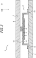
- FIG. 2 is an XY plane cross-sectional view of the tactile sensation providing apparatus 1 taken along line L-L illustrated in FIG. 1 .
- the tactile sensation providing apparatus 1 has a rectangular parallelepiped shape in appearance.
- a thickness direction of the tactile sensation providing apparatus 1 will be referred to as an X-axis direction in FIG. 1 and FIG. 2 .
- a longitudinal direction of the tactile providing apparatus 1 will be referred to as a Y-axis direction.
- a transverse direction of the tactile sensation providing apparatus 1 will be referred to as a Z-axis direction.
- the tactile sensation providing apparatus 1 vibrates a vibration object 2 and thus provides a tactile sensation to a user who is touching a main surface 2a of the vibration object 2.
- Examples of the tactile sensation providing apparatus 1 include a vehicle-mounted apparatus such as a car navigation system, a steering wheel, or a power window switch, or the like.
- examples of the tactile sensation providing apparatus 1 include a mobile phone, a smartphone, a tablet PC (Personal Computer), or a notebook PC.
- the tactile sensation providing apparatus 1 is not limited thereto.
- the tactile sensation providing apparatus 1 may be various electronic apparatuses including a desktop PC, a home electric appliance, an industrial apparatus (FA (Factory Automation) apparatus), a dedicated terminal, or the like.
- FA Fractory Automation
- the tactile sensation providing apparatus 1 includes the vibration object 2, a housing 3, and an actuator 10, as illustrated in FIG. 1 and FIG. 2 .
- the vibration object 2 includes the main surface 2a.
- the user touches the main surface 2a with a finger or the like.
- the vibration object 2 may be a touch sensor arranged in a display panel.
- the vibration object 2 is not limited to the touch sensor.
- the vibration object 2 may be a switch.
- a vibration of the actuator 10 is transmitted to the vibration object 2.
- the vibration object 2 is vibrated when the vibration object 2 receives the vibration of the actuator 10.
- a vibrating direction of the vibration object 2 includes, for example, an in-plane direction and an out-of-plane direction.
- the in-plane direction is a direction substantially parallel to the main surface 2a of the vibration object 2.
- the in-plane direction is a direction parallel to a ZY plane in FIG. 1 .
- a vibration in the in-plane direction corresponds to, for example, a vibration in the Z-axis direction in FIG. 1 .
- the out-of-plane direction is a direction orthogonal to the main surface 2a of the vibration object 2.
- a vibration in the out-of-plane direction corresponds to a vibration in the X-axis direction in FIG. 1 .
- the vibration in the in-plane direction will also be referred to as "transverse vibration”.
- the vibration in the out-of-plane direction will also be referred to as "longitudinal vibration”.
- the housing 3 may be formed from metal, synthetic resin, or the like.
- the housing 3 protects the internal structure of the tactile sensation providing apparatus 1.
- the housing 3 may enclose the actuator 10, a controller, a memory, and the like.
- the controller may be a processor, a microcomputer or the like that is capable of executing application software.
- the controller is connected to the actuator 10.
- the controller outputs a driving signal for vibrating the actuator 10 to the actuator 10.
- the driving signal may be a voltage signal or a current signal.
- the memory may be a semiconductor memory, a magnetic memory, or the like.
- the memory stores various information and programs for operating the controller.
- the controller and the memory may be provided external to the housing 3.
- the actuator 10 is arranged between the vibration object 2 and the housing 3, as illustrated in FIG. 2 .
- Actuators 10 may be arranged at four corners of the tactile sensation providing apparatus 1 having a rectangular parallelepiped shape as illustrated in FIG. 1 .
- the actuator 10 converts the voltage signal output by the controller of the tactile sensation providing apparatus 1 into a vibration.
- the vibration converted by the actuator 10 is transmitted to the vibration object 2.
- the actuator 10 vertically vibrates the vibration object 2.
- the vibration object 2 may be laterally vibrated by appropriately changing the arrangement of the actuator 10.
- FIG. 3 is a perspective view of the actuator 10 illustrated in FIG. 2 as viewed from a side on which the vibration object 2 is located.
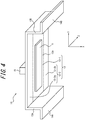
- FIG. 4 is a perspective view of the actuator 10 illustrated in FIG. 2 as viewed from a side on which the housing 3 is located.
- the actuator 10 includes a piezoelectric element 11, a diaphragm 12, supporting portions 13A and 13B, fixing portions 14A and 14B, and a retainer 15.
- the diaphragm 12, the support portions 13A and 13B, and the fixing portions 14A and 14B may be integrally formed by, for example, bending one thin plate.
- the diaphragm 12, the support portions 13A and 13B, and the fixing portions 14A and 14B may be formed from separate members.
- the diaphragm 12, the support portions 13A and 13B, and the fixing portions 14A and 14B are formed from separate members, the diaphragm 12, the support portions 13A and 13B, and the fixing portions 14A and 14B may be integrated by welding or the like.
- the piezoelectric element 11 has, for example, a rectangular shape.
- the voltage signal output from the controller of the tactile sensation providing apparatus 1 is applied to the piezoelectric element 11.
- the piezoelectric element 11 is displaced expanding and contracting in the longitudinal direction according to the voltage signal applied thereto.
- the piezoelectric element 11 may be a piezoelectric film or a piezoelectric ceramic.
- the piezoelectric ceramic can generate a vibration with greater vibrational energy than a piezoelectric film.
- the piezoelectric element 11 may be substituted by a magnetostrictor.
- the magnetostrictor expands and contracts according to a magnetic field applied thereto.
- the actuator 10 may include a coil or the like that converts the driving signal output from the controller of the tactile sensation providing apparatus 1 illustrated in FIG. 1 into a magnetic field.
- the diaphragm 12 is a plate having elasticity such as, for example, a shim plate.
- the diaphragm 12 may be a plate-like member having a predetermined thickness.
- the diaphragm 12 may be formed from metal, resin, or a composite material of metal, resin, and the like.
- One end of the diaphragm 12 is supported by the support portion 13A.
- the other end of the diaphragm 12 is supported by the support portion 13B.
- main surface 12a a surface facing the housing 3
- a surface facing the vibration object 2 will also be referred to as "main surface 12b".
- the diaphragm 12 converts the expanding and contracting displacement of the piezoelectric element 11 into a vibration in a predetermined direction.
- the mechanism in which the diaphragm 12 converts the expanding and contracting displacement of the piezoelectric element 11 into the vibration in the predetermined direction will also be referred to as "conversion mechanism”.
- the diaphragm 12 supports the vibration object 2 illustrated in FIG. 2 described above with respect to the housing 3 in a displaceable manner.
- the mechanism in which the diaphragm 12 supports the vibration object 2 in the displaceable manner will also be referred to as "support mechanism”.
- the conversion mechanism is assumed to be implemented by a first plate 12-1 of the diaphragm 12, for convenience of description.
- the support mechanism is assumed to be implemented by a second plate 12-2 of the diaphragm 12.
- the diaphragm 12 as a whole may implement the conversion mechanism and the support mechanism.
- the first plate 12-1 and the second plate 12-2 may be formed from the same material or different materials.
- the first plate 12-1 implements the conversion mechanism.
- the piezoelectric element 11 may be provided on the main surface 12a of the first plate 12-1.
- the piezoelectric element 11 may be provided on the main surface 12a of the first plate 12-1 so that the longitudinal direction of the piezoelectric element 11 matches the longitudinal direction of the diaphragm 12.
- the piezoelectric element 11 may be bonded to the main surface 12a of the first plate 12-1 via an adhesive or the like.
- the structure in which the piezoelectric element is provided on the main surface 12a of the first plate 12-1 is a so-called unimorph.
- the first plate 12-1 vibrates so that the amplitude in the normal of the main surface 12a in the vicinity of the center of the first plate 12-1 is maximized.
- the first plate 12-1 converts the expanding and contracting displacement of the piezoelectric element 11 into a vibration in the normal (X-axis direction) of the main surface 12a in the vicinity of the center of the first plate 12-1.
- the first plate 12-1 has a first spring constant K1.
- the first spring constant K1 may be determined based on a desired amplitude (a maximum displacement value) in the normal of the main surface 12a in the vicinity of the center of the first plate 12-1.
- the first spring constant K1 may be calculated by dividing a force applied to the first plate 12-1 when the expanding and contracting displacement of the piezoelectric element 11 is maximized, by a desired amplitude in the normal of the main surface 12a in the vicinity of the center of the first plate 12-1.
- the first spring constant K1 can be calculated from the following equation (1).
- K 1 F 1 / U 1
- F1 is a force applied to the first plate 12-1 when the expanding and contracting displacement of the piezoelectric element 11 is maximized.
- U1 is a desired amplitude in the normal of the main surface 12a in the vicinity of the center of the first plate 12-1.
- the second plate 12-2 implements a support mechanism.
- the second plate 12-2 supports the vibration object 2 such that the vibration of the first plate 12-1 is transmitted to the vibration object 2 and whereby the vibration object 2 is displaced with respect to the housing 3, namely, the vibration object 2 is vibrated. That is, the second plate 12-2 supports the vibration object 2 so that the vibration object 2 vibrates and thus provides a tactile sensation to the user.
- the second plate 12-2 may have a plate 12-2a located on one side of the first plate 12-1 and a plate 12-2b located on the other side of the first plate 12-2.
- the second plate 12-2 has a second spring constant K2.
- the second spring constant K2 may be a sum of a spring constant of the plate 12-2a and a spring constant of the plate 12-2b.
- the second spring constant K2 may be determined based on a desired amplitude of the vibration object 2.
- the second spring constant K2 may be calculated by dividing a force applied to the second plate 12-2 when the expanding and contracting displacement of the piezoelectric element 11 is maximized, by the desired amplitude of the vibration object 2.
- the second spring constant K2 can be calculated from the following equation (2).
- K 2 F 2 ⁇ F 1 / U 2
- F2 is a force applied to the diaphragm 12 when the expanding and contracting displacement of the piezoelectric element 11 is maximized.
- a force applied to the second plate 12-2 when the expanding and contracting displacement of the piezoelectric element 11 is maximized can be calculated from a formula (F2-F1).
- U2 is the desired amplitude of the vibration object 2.
- a spring constant Ku of the diaphragm 12 is a sum of the first spring constant K1 and the second spring constant K2.
- the spring constant Ku can be calculated from an equation (3).
- Ku K 1 + K 2
- FIG. 5 illustrates a driving characteristic of the actuator 10.
- the horizontal axis represents a displacement.
- the vertical axis represents a force.
- a characteristic C1 represents a driving characteristic of a configuration in which the piezoelectric element 11 is bonded to the main surface 12a of the first plate 12-1, i.e., a driving characteristic of the unimorph.
- a characteristic C2 represents a characteristic of a load applied to the unimorph by the vibration object 2 or the like via the diaphragm 12.
- F0 is, for example, a maximum value of the force generated in the unimorph when a maximum value of the voltage is applied to the piezoelectric element 11.
- F0 is a force generated in the piezoelectric element 11 when the displacement of the first plate 12-1 is 0.
- Umax is a maximum value of the displacement of unimorph, that is, an amplitude in the normal of the main surface 12a in the vicinity of the center of the first plate 12-1.
- the actuator 10 operates at a point where the force generated in the unimorph and the load applied to the unimorph are in balance.
- an operating point of the actuator 10 is an intersection P of the characteristic C1 and the characteristic C2.
- a maximum displacement value of the actuator 10, i.e., the amplitude (maximum displacement) of the vibration object 2 is U2.
- the load applied to the unimorph by the vibration object 2 and the like via the diaphragm 12 is F2.
- the support portion 13A illustrated in FIG. 3 and FIG. 4 is provided at one end of the longitudinal direction of the diaphragm 12. One end of the support 13A is connected to the diaphragm 12. The other end of the support portion 13A is connected to the fixing portion 14A.
- the support portion 13B is provided on the other end of the longitudinal direction of the diaphragm 12. One end of the support portion 13B is connected to the diaphragm 12. The other end of the support 13B is connected to the fixing portion 14B.
- the supporting portions 13A and 13B support the diaphragm 12 in a manner so that a gap is formed between the piezoelectric element 11 and the housing 3.
- the gap formed between the piezoelectric element 11 and the housing 3 can suppress the piezoelectric element 11 from colliding with the housing 3 when the diaphragm 12 is vibrated according to the vibration of the piezoelectric element 11.
- the support portions 13A and 13B may be formed from the same material as the diaphragm 12 or a material different from that of the diaphragm 12.
- the fixing portions 14A and 14B are fixed to the housing 3.
- the fixing portions 14A and 14B may be fixed to the housing 3 via, for example, a fastening member such as a screw or an adhesive.
- the fixing portions 14A and 14B may be formed from the same material as the diaphragm 12 or a material different from that of the diaphragm 12.
- the retainer 15 supports the vibration object 2.
- the retainer 15 may be formed from a metal, a resin, or a composite material of metal, resin, and the like.
- the retainer 15 is provided in the vicinity the center of the main surface 12b of the diaphragm 12.
- the retainer 15 is connected to the diaphragm 12 via an adhesive or the like. Further, the vibration object 2 is bonded to the retainer 15 with an adhesive or the like.
- FIG. 6 is a cross-sectional view of a tactile sensation providing apparatus 1X according to a comparative example.
- FIG. 6 corresponds to FIG. 2 described above.
- the tactile sensation providing apparatus 1X according to the comparative example includes the vibration object 2, the housing 3, an actuator 10X, and an elastic member 20X.
- the actuator 10X includes the piezoelectric element 11, a diaphragm 12X, the support portions 13A and 13B, the fixing portions 14A and 14B, and the retainer 15.
- the diaphragm 12X has the same shape as the first plate 12-1 illustrated in FIG. 3 and FIG. 4 described above.
- the diaphragm 12X corresponds to the first plate 12-1.
- the diaphragm 12X converts the expanding and contracting displacement of the piezoelectric element 11 into a vibration in a predetermined direction, in a manner similar to the first plate 12-1.
- the diaphragm 12X has a first spring constant K1, in a manner similar to the first plate 12-1.
- the elastic member 20X is, for example, a coil spring.
- the elastic member 20X is connected between the vibration object 2 and the housing 3.
- the elastic member 20X corresponds to the second plate 12-2 illustrated in FIG. 3 and FIG. 4 described above. In other words, the elastic member 20X supports the vibration object 2 with respect to the housing 3 in a displaceable manner, in a manner similar to the second plate 12-2.
- the elastic member 20X has a second spring constant K2, in a manner similar to the second plate 12-2.
- the actuator 10X and the elastic member 20X are connected in parallel between the vibration object 2 and the housing 3.
- the tactile sensation providing apparatus 1X can provide a tactile sensation to the user by vibrating the vibration object 2 using the actuator 10X and the elastic member 20X, in a manner similar to the tactile sensation providing apparatus 1 according to the present embodiment.
- the tactile sensation providing apparatus 1X according to the comparative example includes an elastic member 20X in addition to the actuator 10X. This increases the number of elements used in the tactile sensation providing apparatus 1X according to the comparative example. An increase in the number of elements used in the tactile providing apparatus 1X may lead to an increase in an assembly process or the manufacturing cost of the tactile providing apparatus 1X.
- the tactile sensation providing apparatus 1 can cause the actuator 10 to vibrate the vibration object 2 such that a tactile sensation is provided to the user, without using the elastic member 20X.
- the present embodiment can reduce the number of elements used in the tactile sensation providing apparatus 1. According to the present embodiment, by reducing the number of elements used in the tactile providing apparatus 1, the probability to increase an assembly process and the manufacturing cost of the tactile sensation providing apparatus 1 can be reduced.
- the elastic member 20X needs to be mounted on the housing 3 or the like in addition to the actuator 10X. This may increase a mounting area of elements or the like in the tactile sensation providing apparatus 1X according to the comparative example.
- the present embodiment does not need the elastic member 20X to be mounted on the housing 3 or the like.
- the present embodiment can reduce the probability to increase the mounting area of elements or the like.
- FIG. 7 is a perspective view of an actuator 110 according to another embodiment of the present disclosure.
- the actuator 110 includes the piezoelectric element 11, a diaphragm 112, support portions 113A, 113B, 113C and 113D, and fixing portions 114A, 114B, 114C and 114D.
- the diaphragm 112 has a cross shape.
- the diaphragm 112 has a first plate 12-1 and a second plate 12-3.
- the second plate 12-3 extends from the vicinity of the center of the first plate 12-1.
- the second plate 12-3 has a support mechanism, in a manner similar to the second plate 12-2 illustrated in FIG. 3 .
- the second plate 12-3 has a second spring constant K2.
- a spring constant Ku of the diaphragm 112 is based on a first spring constant K1 and the second spring constant K2, in a manner similar to the diaphragm 12 illustrated in FIG. 3 described above.
- the first plate 12-1 and the second plate 12-3 are connected in parallel between the vibration object 2 and the housing 3 via the supporting portions 113A to 113D, the fixing portions 114A to 114E, and the retainer 15.
- the spring constant Ku of the diaphragm 112 is given by the sum of the first spring constant K1 and the second spring constant K2, in a manner similar to the diaphragm 12 illustrated in FIG. 3 .
- the support portion 113A is provided at one end of the longitudinal direction of the first plate 12-1. One end of the support 113A is connected to the first plate 12-1. The other end of the support portion 113A is connected to the fixing portion 114A.
- the support portion 113B is provided at the other end of the longitudinal direction of the first plate 12-1. One end of the supporting portion 113B is connected to the first plate 12-1. The other end of the support 113B is connected to the fixing 114B.
- the support portion 113C is provided at one end of the longitudinal direction of the second plate 12-3. One end of the support 113C is connected to the second plate 12-3. The other end of the support portion 113C is connected to the fixing portion 114C.
- the support 113D is provided at the other end of the longitudinal direction of the second plate 12-3. One end of the support portion 113C is connected to the second plate 12-3. The other end of the support portion 113C is connected to the fixing portion 114D.
- the fixing portions 114A to 114D are fixed to the housing 3 illustrated in FIG. 2 described above.
- the fixing portions 114A to 114D may be fixed to the housing 3 via a fastening member such as, for example, a screw or an adhesive.
- the actuator 110 as described above can exert an effect similar to that of the actuator 10 illustrated in FIG. 2 described above.
- FIG. 8 is a perspective view of an actuator 210 according to still another embodiment of the present disclosure.
- the actuator 210 includes the piezoelectric element 11, a diaphragm 212, and the retainer 15.
- the diaphragm 212 has a first plate 212-1 and a second plate 12-2.
- the first plate 212-1 has the conversion function, in a manner similar to the first plate 12-1 illustrated in FIG. 3 described above.
- the first plate 212-1 has a first spring constant K1, in a manner similar to the first plate 12-1 illustrated in FIG. 3 described above.
- a through hole 12A is formed at one end of the first plate 212-1.
- a through hole 12B is formed on the other side of the first plate 212-1.
- Fixing members 30A and 30B are arranged between the diaphragm 212 and the housing 3.
- the fixing member 30A has a through hole 31A.
- the fixing member 30B has a through hole 31B.
- One end of the diaphragm 212 is fixed to the housing 3 via the fixing member 30A.
- a fastening member 40A such as, for example, a bolt or the like is inserted into a through hole 3A, the through hole 31A, and the through hole 12A of the housing 3, and a nut 41A is screwed into the fastening member 40A, whereby one end of the diaphragm 212 is fixed to the housing 3 via the fixing member 30A.
- the other end of the diaphragm 212 is fixed to the housing 3 via the fixing member 30B.
- a fastening member 40B such as, for example, a bolt or the like is inserted into the through hole 3B, the through hole 31B, and the through hole 12B of the housing 3, and a nut 41B is screwed into the fastening member 40B, whereby the other end of the diaphragm 212 is fixed to the housing 3 via the fixing member 30B.
- the actuator 210 configured as described above can exert an effect similar to that of the actuator 10 illustrated in FIG. 2 described above.
- the diaphragm 12 has been described to include the first plate 12-1 for implementing the conversion mechanism and the second plate 12-2 for implementing the support mechanism, for convenience of description.
- the diaphragm 12 as a whole may implement the conversion mechanism and the support mechanism.
- the spring constant Ku of the diaphragm 12 may be appropriately adjusted by appropriately determining the shape of the diaphragm 12 as a whole or the material of the diaphragm 12.
- the vibration object 2 is vibrated in the longitudinal direction by the actuator 10.
- the vibration object 2 may be vibrated in the lateral direction by the actuator 10.
- the actuator 10 may be arranged between the vibration object 2 and the housing 3 so that the main surface 12a illustrated in FIG. 4 is perpendicular to the main surface 2a of the vibration object 2 illustrated in FIG. 2 .
- the fixing portions 14A and 14B of the actuator 10 are described to be fixed to the housing 3 of the tactile sensation providing apparatus 1.
- the fixing portions 14A and 14B of the actuator 10 may be fixed to a member other than the housing 3.
- the fixing portions 14A and 14B of the actuator 10 may be fixed to a frame of the vehicle. The same applies to the fixing portions 114A to 11D of the actuator 110.
Landscapes
- Engineering & Computer Science (AREA)
- General Engineering & Computer Science (AREA)
- Theoretical Computer Science (AREA)
- Physics & Mathematics (AREA)
- General Physics & Mathematics (AREA)
- Human Computer Interaction (AREA)
- Mechanical Engineering (AREA)
- Apparatuses For Generation Of Mechanical Vibrations (AREA)
- User Interface Of Digital Computer (AREA)
Abstract
Description
- This application claims priority to and the benefit of Japanese Patent Application No.
2018-101813 filed on May 28, 2018 - The present disclosure relates to an actuator and a tactile sensation providing apparatus.
- Conventionally, apparatuses to provide a tactile sensation to a user are known (e.g., PTL 1 set forth below). The apparatus described in the PTL 1 provides a tactile sensation to a user who is touching a vibration object, by vibrating the vibration object such as a touch sensor using an actuator.
- PTL 1:
JP-A-2017-175874 - An actuator according to one embodiment includes a piezoelectric element and a diaphragm that has the piezoelectric element connected thereto and vibrates according to an expanding and contracting displacement of the piezoelectric element. The diaphragm converts the expanding and contracting displacement of the piezoelectric element into a vibration in a predetermined direction. The diaphragm supports a vibration object for providing a tactile sensation, in a displaceable manner.
- A tactile sensation providing apparatus includes a vibration object for providing a tactile sensation and an actuator. The actuator includes a piezoelectric element and a diaphragm that has the piezoelectric element connected thereto and vibrates according to an expanding and contracting displacement of the piezoelectric element. The diaphragm converts the expanding and contracting displacement of the piezoelectric element into a vibration in a predetermined direction. The diaphragm supports the vibration object for providing a tactile sensation, in a displaceable manner.
- In the accompanying drawings:
-
FIG. 1 is a diagram illustrating an exterior configuration of a tactile sensation providing apparatus according to an embodiment of the present disclosure; -
FIG. 2 is an XY plane cross-sectional view of the tactile sensation providing apparatus taken along line L-L illustrated inFIG. 1 ; -
FIG. 3 is a perspective view of an actuator illustrated inFIG. 2 as viewed from a vibration object side; -
FIG. 4 is a perspective view of the actuator illustrated inFIG. 2 as viewed from a housing side; -
FIG. 5 is a graph illustrating a driving characteristic of the actuator; -
FIG. 6 is a cross-sectional view of a tactile sensation providing apparatus according to a comparative example; -
FIG. 7 is a perspective view of an actuator according to another embodiment of the present disclosure; and -
FIG. 8 is a perspective view of an actuator according to still another embodiment of the present disclosure. - Conventional apparatuses are required to reduce the number of elements used therein for cost reduction and simplification of an assembly process.
- The present disclosure aims to provide an actuator and a tactile sensation providing apparatus that can reduce the number of elements.
- According to the present disclosure, an actuator and a tactile sensation providing apparatus that can reduce the number of elements can be provided.
- Hereinafter, embodiments according to the present disclosure will be described with reference to the drawings. Hereinafter, the same reference numerals will be given to common elements in each drawing. Note that the drawings used in the following description are merely schematic. The drawings are not necessarily drawn to scale.
-
FIG. 1 is a diagram illustrating an exterior configuration of a tactile sensation providing apparatus 1 according to an embodiment of the present disclosure.FIG. 2 is an XY plane cross-sectional view of the tactile sensation providing apparatus 1 taken along line L-L illustrated inFIG. 1 . As illustrated inFIG. 1 , the tactile sensation providing apparatus 1 has a rectangular parallelepiped shape in appearance. Hereinafter, a thickness direction of the tactile sensation providing apparatus 1 will be referred to as an X-axis direction inFIG. 1 andFIG. 2 . A longitudinal direction of the tactile providing apparatus 1 will be referred to as a Y-axis direction. A transverse direction of the tactile sensation providing apparatus 1 will be referred to as a Z-axis direction. - The tactile sensation providing apparatus 1 vibrates a
vibration object 2 and thus provides a tactile sensation to a user who is touching amain surface 2a of thevibration object 2. Examples of the tactile sensation providing apparatus 1 include a vehicle-mounted apparatus such as a car navigation system, a steering wheel, or a power window switch, or the like. Further, examples of the tactile sensation providing apparatus 1 include a mobile phone, a smartphone, a tablet PC (Personal Computer), or a notebook PC. However, the tactile sensation providing apparatus 1 is not limited thereto. The tactile sensation providing apparatus 1 may be various electronic apparatuses including a desktop PC, a home electric appliance, an industrial apparatus (FA (Factory Automation) apparatus), a dedicated terminal, or the like. - The tactile sensation providing apparatus 1 includes the
vibration object 2, ahousing 3, and anactuator 10, as illustrated inFIG. 1 andFIG. 2 . - The
vibration object 2 includes themain surface 2a. The user touches themain surface 2a with a finger or the like. Thevibration object 2 may be a touch sensor arranged in a display panel. However, thevibration object 2 is not limited to the touch sensor. For example, thevibration object 2 may be a switch. A vibration of theactuator 10 is transmitted to thevibration object 2. Thevibration object 2 is vibrated when thevibration object 2 receives the vibration of theactuator 10. - A vibrating direction of the
vibration object 2 includes, for example, an in-plane direction and an out-of-plane direction. The in-plane direction is a direction substantially parallel to themain surface 2a of thevibration object 2. For example, the in-plane direction is a direction parallel to a ZY plane inFIG. 1 . Thus, a vibration in the in-plane direction corresponds to, for example, a vibration in the Z-axis direction inFIG. 1 . The out-of-plane direction is a direction orthogonal to themain surface 2a of thevibration object 2. Thus, a vibration in the out-of-plane direction corresponds to a vibration in the X-axis direction inFIG. 1 . Hereinafter, the vibration in the in-plane direction will also be referred to as "transverse vibration". Also, the vibration in the out-of-plane direction will also be referred to as "longitudinal vibration". - The
housing 3 may be formed from metal, synthetic resin, or the like. Thehousing 3 protects the internal structure of the tactile sensation providing apparatus 1. Thehousing 3 may enclose theactuator 10, a controller, a memory, and the like. The controller may be a processor, a microcomputer or the like that is capable of executing application software. The controller is connected to theactuator 10. The controller outputs a driving signal for vibrating theactuator 10 to theactuator 10. The driving signal may be a voltage signal or a current signal. The memory may be a semiconductor memory, a magnetic memory, or the like. The memory stores various information and programs for operating the controller. The controller and the memory may be provided external to thehousing 3. - The
actuator 10 is arranged between thevibration object 2 and thehousing 3, as illustrated inFIG. 2 .Actuators 10 may be arranged at four corners of the tactile sensation providing apparatus 1 having a rectangular parallelepiped shape as illustrated inFIG. 1 . Theactuator 10 converts the voltage signal output by the controller of the tactile sensation providing apparatus 1 into a vibration. The vibration converted by theactuator 10 is transmitted to thevibration object 2. Theactuator 10 vertically vibrates thevibration object 2. Thevibration object 2 may be laterally vibrated by appropriately changing the arrangement of theactuator 10. -
FIG. 3 is a perspective view of theactuator 10 illustrated inFIG. 2 as viewed from a side on which thevibration object 2 is located.FIG. 4 is a perspective view of theactuator 10 illustrated inFIG. 2 as viewed from a side on which thehousing 3 is located. - The
actuator 10 includes apiezoelectric element 11, adiaphragm 12, supportingportions portions retainer 15. Thediaphragm 12, thesupport portions portions diaphragm 12, thesupport portions portions diaphragm 12, thesupport portions portions diaphragm 12, thesupport portions portions - The
piezoelectric element 11 has, for example, a rectangular shape. The voltage signal output from the controller of the tactile sensation providing apparatus 1 is applied to thepiezoelectric element 11. Thepiezoelectric element 11 is displaced expanding and contracting in the longitudinal direction according to the voltage signal applied thereto. Thepiezoelectric element 11 may be a piezoelectric film or a piezoelectric ceramic. The piezoelectric ceramic can generate a vibration with greater vibrational energy than a piezoelectric film. - The
piezoelectric element 11 may be substituted by a magnetostrictor. The magnetostrictor expands and contracts according to a magnetic field applied thereto. In a case in which thepiezoelectric element 11 is substituted by the magnetostrictor, theactuator 10 may include a coil or the like that converts the driving signal output from the controller of the tactile sensation providing apparatus 1 illustrated inFIG. 1 into a magnetic field. - The
diaphragm 12 is a plate having elasticity such as, for example, a shim plate. Thediaphragm 12 may be a plate-like member having a predetermined thickness. Thediaphragm 12 may be formed from metal, resin, or a composite material of metal, resin, and the like. One end of thediaphragm 12 is supported by thesupport portion 13A. The other end of thediaphragm 12 is supported by thesupport portion 13B. Hereinafter, of the two surfaces of thediaphragm 12, a surface facing thehousing 3 will also be referred to as "main surface 12a". Further, of the two surfaces of thediaphragm 12, a surface facing thevibration object 2 will also be referred to as "main surface 12b". - The
diaphragm 12 converts the expanding and contracting displacement of thepiezoelectric element 11 into a vibration in a predetermined direction. Hereinafter, the mechanism in which thediaphragm 12 converts the expanding and contracting displacement of thepiezoelectric element 11 into the vibration in the predetermined direction will also be referred to as "conversion mechanism". Also, thediaphragm 12 supports thevibration object 2 illustrated inFIG. 2 described above with respect to thehousing 3 in a displaceable manner. Hereinafter, the mechanism in which thediaphragm 12 supports thevibration object 2 in the displaceable manner will also be referred to as "support mechanism". Hereinafter, the conversion mechanism is assumed to be implemented by a first plate 12-1 of thediaphragm 12, for convenience of description. Also, the support mechanism is assumed to be implemented by a second plate 12-2 of thediaphragm 12. However, thediaphragm 12 as a whole may implement the conversion mechanism and the support mechanism. The first plate 12-1 and the second plate 12-2 may be formed from the same material or different materials. - The first plate 12-1 implements the conversion mechanism. The
piezoelectric element 11 may be provided on themain surface 12a of the first plate 12-1. Thepiezoelectric element 11 may be provided on themain surface 12a of the first plate 12-1 so that the longitudinal direction of thepiezoelectric element 11 matches the longitudinal direction of thediaphragm 12. Thepiezoelectric element 11 may be bonded to themain surface 12a of the first plate 12-1 via an adhesive or the like. The structure in which the piezoelectric element is provided on themain surface 12a of the first plate 12-1 is a so-called unimorph. For example, when thepiezoelectric element 11 is displaced expanding and contracting, the first plate 12-1 vibrates so that the amplitude in the normal of themain surface 12a in the vicinity of the center of the first plate 12-1 is maximized. In other words, the first plate 12-1 converts the expanding and contracting displacement of thepiezoelectric element 11 into a vibration in the normal (X-axis direction) of themain surface 12a in the vicinity of the center of the first plate 12-1. - The first plate 12-1 has a first spring constant K1. The first spring constant K1 may be determined based on a desired amplitude (a maximum displacement value) in the normal of the
main surface 12a in the vicinity of the center of the first plate 12-1. For example, the first spring constant K1 may be calculated by dividing a force applied to the first plate 12-1 when the expanding and contracting displacement of thepiezoelectric element 11 is maximized, by a desired amplitude in the normal of themain surface 12a in the vicinity of the center of the first plate 12-1. In this case, the first spring constant K1 can be calculated from the following equation (1).
- In the equation (1), F1 is a force applied to the first plate 12-1 when the expanding and contracting displacement of the
piezoelectric element 11 is maximized. U1 is a desired amplitude in the normal of themain surface 12a in the vicinity of the center of the first plate 12-1. - The second plate 12-2 implements a support mechanism. For example, the second plate 12-2 supports the
vibration object 2 such that the vibration of the first plate 12-1 is transmitted to thevibration object 2 and whereby thevibration object 2 is displaced with respect to thehousing 3, namely, thevibration object 2 is vibrated. That is, the second plate 12-2 supports thevibration object 2 so that thevibration object 2 vibrates and thus provides a tactile sensation to the user. The second plate 12-2 may have a plate 12-2a located on one side of the first plate 12-1 and a plate 12-2b located on the other side of the first plate 12-2. - The second plate 12-2 has a second spring constant K2. The second spring constant K2 may be a sum of a spring constant of the plate 12-2a and a spring constant of the plate 12-2b. The second spring constant K2 may be determined based on a desired amplitude of the
vibration object 2. For example, the second spring constant K2 may be calculated by dividing a force applied to the second plate 12-2 when the expanding and contracting displacement of thepiezoelectric element 11 is maximized, by the desired amplitude of thevibration object 2. For example, the second spring constant K2 can be calculated from the following equation (2).
- In the equation (2), F2 is a force applied to the
diaphragm 12 when the expanding and contracting displacement of thepiezoelectric element 11 is maximized. A force applied to the second plate 12-2 when the expanding and contracting displacement of thepiezoelectric element 11 is maximized can be calculated from a formula (F2-F1). U2 is the desired amplitude of thevibration object 2. - Here, a spring constant Ku of the
diaphragm 12 is a sum of the first spring constant K1 and the second spring constant K2. For example, the spring constant Ku can be calculated from an equation (3).
-
FIG. 5 illustrates a driving characteristic of theactuator 10. InFIG. 5 , the horizontal axis represents a displacement. The vertical axis represents a force. A characteristic C1 represents a driving characteristic of a configuration in which thepiezoelectric element 11 is bonded to themain surface 12a of the first plate 12-1, i.e., a driving characteristic of the unimorph. A characteristic C2 represents a characteristic of a load applied to the unimorph by thevibration object 2 or the like via thediaphragm 12. F0 is, for example, a maximum value of the force generated in the unimorph when a maximum value of the voltage is applied to thepiezoelectric element 11. In other words, F0 is a force generated in thepiezoelectric element 11 when the displacement of the first plate 12-1 is 0. Umax is a maximum value of the displacement of unimorph, that is, an amplitude in the normal of themain surface 12a in the vicinity of the center of the first plate 12-1. Theactuator 10 operates at a point where the force generated in the unimorph and the load applied to the unimorph are in balance. Thus, an operating point of theactuator 10 is an intersection P of the characteristic C1 and the characteristic C2. Accordingly, a maximum displacement value of theactuator 10, i.e., the amplitude (maximum displacement) of thevibration object 2 is U2. Further, when the displacement of thevibration object 2 is the maximum value of U2, the load applied to the unimorph by thevibration object 2 and the like via thediaphragm 12 is F2. - The
support portion 13A illustrated inFIG. 3 andFIG. 4 is provided at one end of the longitudinal direction of thediaphragm 12. One end of thesupport 13A is connected to thediaphragm 12. The other end of thesupport portion 13A is connected to the fixingportion 14A. Thesupport portion 13B is provided on the other end of the longitudinal direction of thediaphragm 12. One end of thesupport portion 13B is connected to thediaphragm 12. The other end of thesupport 13B is connected to the fixingportion 14B. - The supporting
portions diaphragm 12 in a manner so that a gap is formed between thepiezoelectric element 11 and thehousing 3. The gap formed between thepiezoelectric element 11 and thehousing 3 can suppress thepiezoelectric element 11 from colliding with thehousing 3 when thediaphragm 12 is vibrated according to the vibration of thepiezoelectric element 11. Thesupport portions diaphragm 12 or a material different from that of thediaphragm 12. - The fixing
portions housing 3. The fixingportions housing 3 via, for example, a fastening member such as a screw or an adhesive. The fixingportions diaphragm 12 or a material different from that of thediaphragm 12. - The
retainer 15 supports thevibration object 2. Theretainer 15 may be formed from a metal, a resin, or a composite material of metal, resin, and the like. Theretainer 15 is provided in the vicinity the center of themain surface 12b of thediaphragm 12. Theretainer 15 is connected to thediaphragm 12 via an adhesive or the like. Further, thevibration object 2 is bonded to theretainer 15 with an adhesive or the like. -
FIG. 6 is a cross-sectional view of a tactilesensation providing apparatus 1X according to a comparative example.FIG. 6 corresponds toFIG. 2 described above. The tactilesensation providing apparatus 1X according to the comparative example includes thevibration object 2, thehousing 3, anactuator 10X, and anelastic member 20X. - The
actuator 10X includes thepiezoelectric element 11, adiaphragm 12X, thesupport portions portions retainer 15. - The
diaphragm 12X has the same shape as the first plate 12-1 illustrated inFIG. 3 andFIG. 4 described above. Thediaphragm 12X corresponds to the first plate 12-1. In other words, thediaphragm 12X converts the expanding and contracting displacement of thepiezoelectric element 11 into a vibration in a predetermined direction, in a manner similar to the first plate 12-1. Thediaphragm 12X has a first spring constant K1, in a manner similar to the first plate 12-1. - The
elastic member 20X is, for example, a coil spring. Theelastic member 20X is connected between thevibration object 2 and thehousing 3. - The
elastic member 20X corresponds to the second plate 12-2 illustrated inFIG. 3 andFIG. 4 described above. In other words, theelastic member 20X supports thevibration object 2 with respect to thehousing 3 in a displaceable manner, in a manner similar to the second plate 12-2. Theelastic member 20X has a second spring constant K2, in a manner similar to the second plate 12-2. - The
actuator 10X and theelastic member 20X are connected in parallel between thevibration object 2 and thehousing 3. Thus, a combined spring constant of theactuator 10X and theelastic member 20X coincides with the spring constant Ku (=K1+K2) of thediaphragm 12. Accordingly, the tactilesensation providing apparatus 1X according to the comparative example also can realize the same characteristics as the tactile sensation providing apparatus 1 according to the present embodiment. - As described above, the tactile
sensation providing apparatus 1X according to the comparative example can provide a tactile sensation to the user by vibrating thevibration object 2 using theactuator 10X and theelastic member 20X, in a manner similar to the tactile sensation providing apparatus 1 according to the present embodiment. - However, the tactile
sensation providing apparatus 1X according to the comparative example includes anelastic member 20X in addition to theactuator 10X. This increases the number of elements used in the tactilesensation providing apparatus 1X according to the comparative example. An increase in the number of elements used in the tactile providingapparatus 1X may lead to an increase in an assembly process or the manufacturing cost of the tactile providingapparatus 1X. - On the other hand, the tactile sensation providing apparatus 1 according to the present embodiment can cause the
actuator 10 to vibrate thevibration object 2 such that a tactile sensation is provided to the user, without using theelastic member 20X. Thus, the present embodiment can reduce the number of elements used in the tactile sensation providing apparatus 1. According to the present embodiment, by reducing the number of elements used in the tactile providing apparatus 1, the probability to increase an assembly process and the manufacturing cost of the tactile sensation providing apparatus 1 can be reduced. - In the tactile
sensation providing apparatus 1X according to the comparative example, further, theelastic member 20X needs to be mounted on thehousing 3 or the like in addition to theactuator 10X. This may increase a mounting area of elements or the like in the tactilesensation providing apparatus 1X according to the comparative example. - On the other hand, the present embodiment does not need the
elastic member 20X to be mounted on thehousing 3 or the like. Thus, the present embodiment can reduce the probability to increase the mounting area of elements or the like. -
FIG. 7 is a perspective view of anactuator 110 according to another embodiment of the present disclosure. Theactuator 110 includes thepiezoelectric element 11, a diaphragm 112,support portions portions - The diaphragm 112 has a cross shape. The diaphragm 112 has a first plate 12-1 and a second plate 12-3.
- The second plate 12-3 extends from the vicinity of the center of the first plate 12-1. The second plate 12-3 has a support mechanism, in a manner similar to the second plate 12-2 illustrated in
FIG. 3 . The second plate 12-3 has a second spring constant K2. - A spring constant Ku of the diaphragm 112 is based on a first spring constant K1 and the second spring constant K2, in a manner similar to the
diaphragm 12 illustrated inFIG. 3 described above. The first plate 12-1 and the second plate 12-3 are connected in parallel between thevibration object 2 and thehousing 3 via the supportingportions 113A to 113D, the fixingportions 114A to 114E, and theretainer 15. Thus, the spring constant Ku of the diaphragm 112 is given by the sum of the first spring constant K1 and the second spring constant K2, in a manner similar to thediaphragm 12 illustrated inFIG. 3 . - The
support portion 113A is provided at one end of the longitudinal direction of the first plate 12-1. One end of thesupport 113A is connected to the first plate 12-1. The other end of thesupport portion 113A is connected to the fixingportion 114A. Thesupport portion 113B is provided at the other end of the longitudinal direction of the first plate 12-1. One end of the supportingportion 113B is connected to the first plate 12-1. The other end of thesupport 113B is connected to the fixing 114B. - The
support portion 113C is provided at one end of the longitudinal direction of the second plate 12-3. One end of thesupport 113C is connected to the second plate 12-3. The other end of thesupport portion 113C is connected to the fixingportion 114C. Thesupport 113D is provided at the other end of the longitudinal direction of the second plate 12-3. One end of thesupport portion 113C is connected to the second plate 12-3. The other end of thesupport portion 113C is connected to the fixingportion 114D. - The fixing
portions 114A to 114D are fixed to thehousing 3 illustrated inFIG. 2 described above. The fixingportions 114A to 114D may be fixed to thehousing 3 via a fastening member such as, for example, a screw or an adhesive. - The
actuator 110 as described above can exert an effect similar to that of theactuator 10 illustrated inFIG. 2 described above. -
FIG. 8 is a perspective view of anactuator 210 according to still another embodiment of the present disclosure. Theactuator 210 includes thepiezoelectric element 11, adiaphragm 212, and theretainer 15. - The
diaphragm 212 has a first plate 212-1 and a second plate 12-2. The first plate 212-1 has the conversion function, in a manner similar to the first plate 12-1 illustrated inFIG. 3 described above. The first plate 212-1 has a first spring constant K1, in a manner similar to the first plate 12-1 illustrated inFIG. 3 described above. - A through
hole 12A is formed at one end of the first plate 212-1. A throughhole 12B is formed on the other side of the first plate 212-1. - Fixing
members diaphragm 212 and thehousing 3. The fixingmember 30A has a throughhole 31A. The fixingmember 30B has a throughhole 31B. - One end of the
diaphragm 212 is fixed to thehousing 3 via the fixingmember 30A. For example, afastening member 40A such as, for example, a bolt or the like is inserted into a throughhole 3A, the throughhole 31A, and the throughhole 12A of thehousing 3, and anut 41A is screwed into thefastening member 40A, whereby one end of thediaphragm 212 is fixed to thehousing 3 via the fixingmember 30A. - The other end of the
diaphragm 212 is fixed to thehousing 3 via the fixingmember 30B. For example, afastening member 40B such as, for example, a bolt or the like is inserted into the throughhole 3B, the throughhole 31B, and the throughhole 12B of thehousing 3, and anut 41B is screwed into thefastening member 40B, whereby the other end of thediaphragm 212 is fixed to thehousing 3 via the fixingmember 30B. - The
actuator 210 configured as described above can exert an effect similar to that of theactuator 10 illustrated inFIG. 2 described above. - Although the disclosure has been described based on the figures and the embodiments, it is to be understood that various changes and modifications may be implemented based on the present disclosure by those who are ordinarily skilled in the art. Accordingly, such changes and modifications are included in the scope of the disclosure herein. For example, functions and the like included in each functional unit may be rearranged without logical inconsistency. A plurality of functional units may be combined together or subdivided. Each of the embodiments of the disclosure described above does not need to be practiced strictly following the description thereof but may be implemented by appropriately combining or partially omitting features.
- For example, in the embodiments described above, the
diaphragm 12 has been described to include the first plate 12-1 for implementing the conversion mechanism and the second plate 12-2 for implementing the support mechanism, for convenience of description. However, thediaphragm 12 as a whole may implement the conversion mechanism and the support mechanism. In this case, the spring constant Ku of thediaphragm 12 may be appropriately adjusted by appropriately determining the shape of thediaphragm 12 as a whole or the material of thediaphragm 12. - For example, in the embodiments described above the
vibration object 2 is vibrated in the longitudinal direction by theactuator 10. However, thevibration object 2 may be vibrated in the lateral direction by theactuator 10. In this case, theactuator 10 may be arranged between thevibration object 2 and thehousing 3 so that themain surface 12a illustrated inFIG. 4 is perpendicular to themain surface 2a of thevibration object 2 illustrated inFIG. 2 . The same applies to theactuators - For example, in the embodiments described above the fixing
portions actuator 10 are described to be fixed to thehousing 3 of the tactile sensation providing apparatus 1. However, the fixingportions actuator 10 may be fixed to a member other than thehousing 3. For example, in a case in which the tactile sensation providing apparatus 1 is implemented in a vehicle, the fixingportions actuator 10 may be fixed to a frame of the vehicle. The same applies to the fixingportions 114A to 11D of theactuator 110. -
- 1, 1X
- tactile sensation providing apparatus
- 2
- vibration object
- 2a
- main surface
- 3
- housing
- 10, 10X, 110, 210
- actuator
- 11
- piezoelectric element
- 12, 12X, 112, 212
- diaphragm
- 12-1,212-1
- first plate
- 12-2, 12 -3
- second plate
- 13A, 13B, 113A, 113B, 113C, 113D
- supporting portion
- 14A, 14B, 114A, 114B, 114C, 114D
- fixing portion
- 15
- retainer
- 20X
- elastic member
- 30A, 30B
- fixing member
- 3A, 3B, 12A, 12B, 31A, 31B
- through hole
- 40A, 40B
- fastening member
- 41A, 41B
- nut
Claims (4)
- An actuator comprising:a piezoelectric element; anda diaphragm that has the piezoelectric element attached thereto and vibrates according to an expanding and contracting displacement of the piezoelectric element,wherein the diaphragm is configured to convert the expanding and contracting displacement of the piezoelectric element into a vibration in a predetermined direction, andthe diaphragm is configured to support a vibration object for providing a tactile sensation, in a displaceable manner.
- The actuator according to claim 1,
wherein a spring constant of the diaphragm is a sum of a first spring constant determined based on a predetermined amplitude of the diaphragm in a predetermined direction and a second spring constant determined based on a predetermined amplitude of the vibration object. - A tactile sensation providing apparatus comprising:a vibration object for providing a tactile sensation and an actuator,wherein the actuator includesa piezoelectric element; anda diaphragm that has the piezoelectric element attached thereto and vibrates according to an expanding and contracting displacement of the piezoelectric element,wherein the diaphragm is configured to convert the expanding and contracting displacement of the piezoelectric element into a vibration in a predetermined direction, andthe diaphragm is configured to support a vibration object for providing a tactile sensation, in a displaceable manner.
- The tactile sensation providing apparatus according to claim 3, wherein the tactile sensation providing apparatus does not include an elastic member.
Applications Claiming Priority (2)
| Application Number | Priority Date | Filing Date | Title |
|---|---|---|---|
| JP2018101813A JP7154040B2 (en) | 2018-05-28 | 2018-05-28 | Actuator and tactile presentation device |
| PCT/JP2019/019090 WO2019230367A1 (en) | 2018-05-28 | 2019-05-14 | Actuator and tactile sensation presentation device |
Publications (3)
| Publication Number | Publication Date |
|---|---|
| EP3805905A1 true EP3805905A1 (en) | 2021-04-14 |
| EP3805905A4 EP3805905A4 (en) | 2022-03-09 |
| EP3805905B1 EP3805905B1 (en) | 2024-04-10 |
Family
ID=68698622
Family Applications (1)
| Application Number | Title | Priority Date | Filing Date |
|---|---|---|---|
| EP19812615.3A Active EP3805905B1 (en) | 2018-05-28 | 2019-05-14 | Actuator and tactile sensation presentation device |
Country Status (4)
| Country | Link |
|---|---|
| US (1) | US11620882B2 (en) |
| EP (1) | EP3805905B1 (en) |
| JP (1) | JP7154040B2 (en) |
| WO (1) | WO2019230367A1 (en) |
Families Citing this family (2)
| Publication number | Priority date | Publication date | Assignee | Title |
|---|---|---|---|---|
| JP7072492B2 (en) * | 2018-11-22 | 2022-05-20 | 京セラ株式会社 | Actuator and tactile presentation device |
| US11694831B2 (en) * | 2019-09-23 | 2023-07-04 | Apple Inc. | Haptic actuator including outwardly extending terminals from first and second housing shells and related methods |
Family Cites Families (5)
| Publication number | Priority date | Publication date | Assignee | Title |
|---|---|---|---|---|
| WO2007026736A1 (en) | 2005-08-31 | 2007-03-08 | Nec Corporation | Piezoelectric actuator, acoustic element, and electronic device |
| WO2014098429A1 (en) * | 2012-12-17 | 2014-06-26 | (주) 테라다인 | Piezo actuator |
| KR20170108046A (en) * | 2015-01-30 | 2017-09-26 | 임머숀 코퍼레이션 | An electrostatic haptic actuator, and a electrostatic haptic actuator |
| JP2017175805A (en) * | 2016-03-24 | 2017-09-28 | 京セラ株式会社 | Actuator and tactile sensation presentation device |
| JP6955843B2 (en) | 2016-03-25 | 2021-10-27 | 京セラ株式会社 | Actuator and tactile presentation device |
-
2018
- 2018-05-28 JP JP2018101813A patent/JP7154040B2/en active Active
-
2019
- 2019-05-14 EP EP19812615.3A patent/EP3805905B1/en active Active
- 2019-05-14 US US17/057,928 patent/US11620882B2/en active Active
- 2019-05-14 WO PCT/JP2019/019090 patent/WO2019230367A1/en not_active Ceased
Also Published As
| Publication number | Publication date |
|---|---|
| JP7154040B2 (en) | 2022-10-17 |
| WO2019230367A1 (en) | 2019-12-05 |
| US20210312770A1 (en) | 2021-10-07 |
| JP2019207504A (en) | 2019-12-05 |
| EP3805905A4 (en) | 2022-03-09 |
| US11620882B2 (en) | 2023-04-04 |
| EP3805905B1 (en) | 2024-04-10 |
Similar Documents
| Publication | Publication Date | Title |
|---|---|---|
| EP3086207B1 (en) | Electronic device for generating vibrations | |
| US9466783B2 (en) | Suspension element having integrated piezo material for providing haptic effects to a touch screen | |
| EP3442109B1 (en) | Tactile sensation presentation device | |
| JP2014509117A (en) | Flexure apparatus, system, and method | |
| EP3805905B1 (en) | Actuator and tactile sensation presentation device | |
| EP3725094A1 (en) | Reinforced actuators for distributed mode loudspeakers | |
| US10936103B2 (en) | Touch panel-equipped display device | |
| EP3885881B1 (en) | Actuator and tactile presentation device | |
| WO2020110654A1 (en) | Actuator and tactile presentation device | |
| US11318498B2 (en) | Unit and tactile sensation providing apparatus | |
| EP3798803B1 (en) | Tactile sensation providing device | |
| CN221782663U (en) | Vibration structure, panel module and frame module | |
| JP2022164198A (en) | Display device with touch panel |
Legal Events
| Date | Code | Title | Description |
|---|---|---|---|
| STAA | Information on the status of an ep patent application or granted ep patent |
Free format text: STATUS: THE INTERNATIONAL PUBLICATION HAS BEEN MADE |
|
| PUAI | Public reference made under article 153(3) epc to a published international application that has entered the european phase |
Free format text: ORIGINAL CODE: 0009012 |
|
| STAA | Information on the status of an ep patent application or granted ep patent |
Free format text: STATUS: REQUEST FOR EXAMINATION WAS MADE |
|
| 17P | Request for examination filed |
Effective date: 20201124 |
|
| AK | Designated contracting states |
Kind code of ref document: A1 Designated state(s): AL AT BE BG CH CY CZ DE DK EE ES FI FR GB GR HR HU IE IS IT LI LT LU LV MC MK MT NL NO PL PT RO RS SE SI SK SM TR |
|
| AX | Request for extension of the european patent |
Extension state: BA ME |
|
| DAV | Request for validation of the european patent (deleted) | ||
| DAX | Request for extension of the european patent (deleted) | ||
| A4 | Supplementary search report drawn up and despatched |
Effective date: 20220203 |
|
| RIC1 | Information provided on ipc code assigned before grant |
Ipc: G06F 3/01 20060101ALI20220128BHEP Ipc: G06F 3/041 20060101AFI20220128BHEP |
|
| P01 | Opt-out of the competence of the unified patent court (upc) registered |
Effective date: 20230505 |
|
| GRAP | Despatch of communication of intention to grant a patent |
Free format text: ORIGINAL CODE: EPIDOSNIGR1 |
|
| STAA | Information on the status of an ep patent application or granted ep patent |
Free format text: STATUS: GRANT OF PATENT IS INTENDED |
|
| INTG | Intention to grant announced |
Effective date: 20231106 |
|
| GRAS | Grant fee paid |
Free format text: ORIGINAL CODE: EPIDOSNIGR3 |
|
| GRAA | (expected) grant |
Free format text: ORIGINAL CODE: 0009210 |
|
| STAA | Information on the status of an ep patent application or granted ep patent |
Free format text: STATUS: THE PATENT HAS BEEN GRANTED |
|
| AK | Designated contracting states |
Kind code of ref document: B1 Designated state(s): AL AT BE BG CH CY CZ DE DK EE ES FI FR GB GR HR HU IE IS IT LI LT LU LV MC MK MT NL NO PL PT RO RS SE SI SK SM TR |
|
| REG | Reference to a national code |
Ref country code: GB Ref legal event code: FG4D |
|
| REG | Reference to a national code |
Ref country code: CH Ref legal event code: EP |
|
| REG | Reference to a national code |
Ref country code: DE Ref legal event code: R096 Ref document number: 602019050127 Country of ref document: DE |
|
| REG | Reference to a national code |
Ref country code: IE Ref legal event code: FG4D |
|
| REG | Reference to a national code |
Ref country code: LT Ref legal event code: MG9D |
|
| REG | Reference to a national code |
Ref country code: NL Ref legal event code: MP Effective date: 20240410 |
|
| REG | Reference to a national code |
Ref country code: AT Ref legal event code: MK05 Ref document number: 1675573 Country of ref document: AT Kind code of ref document: T Effective date: 20240410 |
|
| PG25 | Lapsed in a contracting state [announced via postgrant information from national office to epo] |
Ref country code: NL Free format text: LAPSE BECAUSE OF FAILURE TO SUBMIT A TRANSLATION OF THE DESCRIPTION OR TO PAY THE FEE WITHIN THE PRESCRIBED TIME-LIMIT Effective date: 20240410 |
|
| PG25 | Lapsed in a contracting state [announced via postgrant information from national office to epo] |
Ref country code: NL Free format text: LAPSE BECAUSE OF FAILURE TO SUBMIT A TRANSLATION OF THE DESCRIPTION OR TO PAY THE FEE WITHIN THE PRESCRIBED TIME-LIMIT Effective date: 20240410 |
|
| PG25 | Lapsed in a contracting state [announced via postgrant information from national office to epo] |
Ref country code: IS Free format text: LAPSE BECAUSE OF FAILURE TO SUBMIT A TRANSLATION OF THE DESCRIPTION OR TO PAY THE FEE WITHIN THE PRESCRIBED TIME-LIMIT Effective date: 20240810 |
|
| PG25 | Lapsed in a contracting state [announced via postgrant information from national office to epo] |
Ref country code: BG Free format text: LAPSE BECAUSE OF FAILURE TO SUBMIT A TRANSLATION OF THE DESCRIPTION OR TO PAY THE FEE WITHIN THE PRESCRIBED TIME-LIMIT Effective date: 20240410 |
|
| PG25 | Lapsed in a contracting state [announced via postgrant information from national office to epo] |
Ref country code: HR Free format text: LAPSE BECAUSE OF FAILURE TO SUBMIT A TRANSLATION OF THE DESCRIPTION OR TO PAY THE FEE WITHIN THE PRESCRIBED TIME-LIMIT Effective date: 20240410 Ref country code: FI Free format text: LAPSE BECAUSE OF FAILURE TO SUBMIT A TRANSLATION OF THE DESCRIPTION OR TO PAY THE FEE WITHIN THE PRESCRIBED TIME-LIMIT Effective date: 20240410 |
|
| PG25 | Lapsed in a contracting state [announced via postgrant information from national office to epo] |
Ref country code: GR Free format text: LAPSE BECAUSE OF FAILURE TO SUBMIT A TRANSLATION OF THE DESCRIPTION OR TO PAY THE FEE WITHIN THE PRESCRIBED TIME-LIMIT Effective date: 20240711 |
|
| PG25 | Lapsed in a contracting state [announced via postgrant information from national office to epo] |
Ref country code: PT Free format text: LAPSE BECAUSE OF FAILURE TO SUBMIT A TRANSLATION OF THE DESCRIPTION OR TO PAY THE FEE WITHIN THE PRESCRIBED TIME-LIMIT Effective date: 20240812 |
|
| PG25 | Lapsed in a contracting state [announced via postgrant information from national office to epo] |
Ref country code: ES Free format text: LAPSE BECAUSE OF FAILURE TO SUBMIT A TRANSLATION OF THE DESCRIPTION OR TO PAY THE FEE WITHIN THE PRESCRIBED TIME-LIMIT Effective date: 20240410 |
|
| PG25 | Lapsed in a contracting state [announced via postgrant information from national office to epo] |
Ref country code: AT Free format text: LAPSE BECAUSE OF FAILURE TO SUBMIT A TRANSLATION OF THE DESCRIPTION OR TO PAY THE FEE WITHIN THE PRESCRIBED TIME-LIMIT Effective date: 20240410 |
|
| PG25 | Lapsed in a contracting state [announced via postgrant information from national office to epo] |
Ref country code: PL Free format text: LAPSE BECAUSE OF FAILURE TO SUBMIT A TRANSLATION OF THE DESCRIPTION OR TO PAY THE FEE WITHIN THE PRESCRIBED TIME-LIMIT Effective date: 20240410 |
|
| PG25 | Lapsed in a contracting state [announced via postgrant information from national office to epo] |
Ref country code: LV Free format text: LAPSE BECAUSE OF FAILURE TO SUBMIT A TRANSLATION OF THE DESCRIPTION OR TO PAY THE FEE WITHIN THE PRESCRIBED TIME-LIMIT Effective date: 20240410 |
|
| PG25 | Lapsed in a contracting state [announced via postgrant information from national office to epo] |
Ref country code: PT Free format text: LAPSE BECAUSE OF FAILURE TO SUBMIT A TRANSLATION OF THE DESCRIPTION OR TO PAY THE FEE WITHIN THE PRESCRIBED TIME-LIMIT Effective date: 20240812 Ref country code: PL Free format text: LAPSE BECAUSE OF FAILURE TO SUBMIT A TRANSLATION OF THE DESCRIPTION OR TO PAY THE FEE WITHIN THE PRESCRIBED TIME-LIMIT Effective date: 20240410 Ref country code: NO Free format text: LAPSE BECAUSE OF FAILURE TO SUBMIT A TRANSLATION OF THE DESCRIPTION OR TO PAY THE FEE WITHIN THE PRESCRIBED TIME-LIMIT Effective date: 20240710 Ref country code: LV Free format text: LAPSE BECAUSE OF FAILURE TO SUBMIT A TRANSLATION OF THE DESCRIPTION OR TO PAY THE FEE WITHIN THE PRESCRIBED TIME-LIMIT Effective date: 20240410 Ref country code: IS Free format text: LAPSE BECAUSE OF FAILURE TO SUBMIT A TRANSLATION OF THE DESCRIPTION OR TO PAY THE FEE WITHIN THE PRESCRIBED TIME-LIMIT Effective date: 20240810 Ref country code: HR Free format text: LAPSE BECAUSE OF FAILURE TO SUBMIT A TRANSLATION OF THE DESCRIPTION OR TO PAY THE FEE WITHIN THE PRESCRIBED TIME-LIMIT Effective date: 20240410 Ref country code: GR Free format text: LAPSE BECAUSE OF FAILURE TO SUBMIT A TRANSLATION OF THE DESCRIPTION OR TO PAY THE FEE WITHIN THE PRESCRIBED TIME-LIMIT Effective date: 20240711 Ref country code: FI Free format text: LAPSE BECAUSE OF FAILURE TO SUBMIT A TRANSLATION OF THE DESCRIPTION OR TO PAY THE FEE WITHIN THE PRESCRIBED TIME-LIMIT Effective date: 20240410 Ref country code: ES Free format text: LAPSE BECAUSE OF FAILURE TO SUBMIT A TRANSLATION OF THE DESCRIPTION OR TO PAY THE FEE WITHIN THE PRESCRIBED TIME-LIMIT Effective date: 20240410 Ref country code: BG Free format text: LAPSE BECAUSE OF FAILURE TO SUBMIT A TRANSLATION OF THE DESCRIPTION OR TO PAY THE FEE WITHIN THE PRESCRIBED TIME-LIMIT Effective date: 20240410 Ref country code: AT Free format text: LAPSE BECAUSE OF FAILURE TO SUBMIT A TRANSLATION OF THE DESCRIPTION OR TO PAY THE FEE WITHIN THE PRESCRIBED TIME-LIMIT Effective date: 20240410 Ref country code: RS Free format text: LAPSE BECAUSE OF FAILURE TO SUBMIT A TRANSLATION OF THE DESCRIPTION OR TO PAY THE FEE WITHIN THE PRESCRIBED TIME-LIMIT Effective date: 20240710 |
|
| REG | Reference to a national code |
Ref country code: CH Ref legal event code: PL |
|
| REG | Reference to a national code |
Ref country code: DE Ref legal event code: R097 Ref document number: 602019050127 Country of ref document: DE |
|
| PG25 | Lapsed in a contracting state [announced via postgrant information from national office to epo] |
Ref country code: DK Free format text: LAPSE BECAUSE OF FAILURE TO SUBMIT A TRANSLATION OF THE DESCRIPTION OR TO PAY THE FEE WITHIN THE PRESCRIBED TIME-LIMIT Effective date: 20240410 |
|
| PG25 | Lapsed in a contracting state [announced via postgrant information from national office to epo] |
Ref country code: LU Free format text: LAPSE BECAUSE OF NON-PAYMENT OF DUE FEES Effective date: 20240514 |
|
| PG25 | Lapsed in a contracting state [announced via postgrant information from national office to epo] |
Ref country code: EE Free format text: LAPSE BECAUSE OF FAILURE TO SUBMIT A TRANSLATION OF THE DESCRIPTION OR TO PAY THE FEE WITHIN THE PRESCRIBED TIME-LIMIT Effective date: 20240410 |
|
| PG25 | Lapsed in a contracting state [announced via postgrant information from national office to epo] |
Ref country code: CZ Free format text: LAPSE BECAUSE OF FAILURE TO SUBMIT A TRANSLATION OF THE DESCRIPTION OR TO PAY THE FEE WITHIN THE PRESCRIBED TIME-LIMIT Effective date: 20240410 |
|
| PG25 | Lapsed in a contracting state [announced via postgrant information from national office to epo] |
Ref country code: RO Free format text: LAPSE BECAUSE OF FAILURE TO SUBMIT A TRANSLATION OF THE DESCRIPTION OR TO PAY THE FEE WITHIN THE PRESCRIBED TIME-LIMIT Effective date: 20240410 Ref country code: SK Free format text: LAPSE BECAUSE OF FAILURE TO SUBMIT A TRANSLATION OF THE DESCRIPTION OR TO PAY THE FEE WITHIN THE PRESCRIBED TIME-LIMIT Effective date: 20240410 |
|
| PG25 | Lapsed in a contracting state [announced via postgrant information from national office to epo] |
Ref country code: SM Free format text: LAPSE BECAUSE OF FAILURE TO SUBMIT A TRANSLATION OF THE DESCRIPTION OR TO PAY THE FEE WITHIN THE PRESCRIBED TIME-LIMIT Effective date: 20240410 |
|
| PG25 | Lapsed in a contracting state [announced via postgrant information from national office to epo] |
Ref country code: SM Free format text: LAPSE BECAUSE OF FAILURE TO SUBMIT A TRANSLATION OF THE DESCRIPTION OR TO PAY THE FEE WITHIN THE PRESCRIBED TIME-LIMIT Effective date: 20240410 Ref country code: SK Free format text: LAPSE BECAUSE OF FAILURE TO SUBMIT A TRANSLATION OF THE DESCRIPTION OR TO PAY THE FEE WITHIN THE PRESCRIBED TIME-LIMIT Effective date: 20240410 Ref country code: RO Free format text: LAPSE BECAUSE OF FAILURE TO SUBMIT A TRANSLATION OF THE DESCRIPTION OR TO PAY THE FEE WITHIN THE PRESCRIBED TIME-LIMIT Effective date: 20240410 Ref country code: LU Free format text: LAPSE BECAUSE OF NON-PAYMENT OF DUE FEES Effective date: 20240514 Ref country code: EE Free format text: LAPSE BECAUSE OF FAILURE TO SUBMIT A TRANSLATION OF THE DESCRIPTION OR TO PAY THE FEE WITHIN THE PRESCRIBED TIME-LIMIT Effective date: 20240410 Ref country code: DK Free format text: LAPSE BECAUSE OF FAILURE TO SUBMIT A TRANSLATION OF THE DESCRIPTION OR TO PAY THE FEE WITHIN THE PRESCRIBED TIME-LIMIT Effective date: 20240410 Ref country code: CZ Free format text: LAPSE BECAUSE OF FAILURE TO SUBMIT A TRANSLATION OF THE DESCRIPTION OR TO PAY THE FEE WITHIN THE PRESCRIBED TIME-LIMIT Effective date: 20240410 Ref country code: MC Free format text: LAPSE BECAUSE OF FAILURE TO SUBMIT A TRANSLATION OF THE DESCRIPTION OR TO PAY THE FEE WITHIN THE PRESCRIBED TIME-LIMIT Effective date: 20240410 Ref country code: CH Free format text: LAPSE BECAUSE OF NON-PAYMENT OF DUE FEES Effective date: 20240531 |
|
| PG25 | Lapsed in a contracting state [announced via postgrant information from national office to epo] |
Ref country code: IT Free format text: LAPSE BECAUSE OF FAILURE TO SUBMIT A TRANSLATION OF THE DESCRIPTION OR TO PAY THE FEE WITHIN THE PRESCRIBED TIME-LIMIT Effective date: 20240410 |
|
| PLBE | No opposition filed within time limit |
Free format text: ORIGINAL CODE: 0009261 |
|
| STAA | Information on the status of an ep patent application or granted ep patent |
Free format text: STATUS: NO OPPOSITION FILED WITHIN TIME LIMIT |
|
| REG | Reference to a national code |
Ref country code: BE Ref legal event code: MM Effective date: 20240531 |
|
| 26N | No opposition filed |
Effective date: 20250113 |
|
| PG25 | Lapsed in a contracting state [announced via postgrant information from national office to epo] |
Ref country code: IE Free format text: LAPSE BECAUSE OF NON-PAYMENT OF DUE FEES Effective date: 20240514 |
|
| PG25 | Lapsed in a contracting state [announced via postgrant information from national office to epo] |
Ref country code: SI Free format text: LAPSE BECAUSE OF FAILURE TO SUBMIT A TRANSLATION OF THE DESCRIPTION OR TO PAY THE FEE WITHIN THE PRESCRIBED TIME-LIMIT Effective date: 20240410 Ref country code: BE Free format text: LAPSE BECAUSE OF NON-PAYMENT OF DUE FEES Effective date: 20240531 |
|
| PGFP | Annual fee paid to national office [announced via postgrant information from national office to epo] |
Ref country code: DE Payment date: 20250402 Year of fee payment: 7 |
|
| PGFP | Annual fee paid to national office [announced via postgrant information from national office to epo] |
Ref country code: FR Payment date: 20250401 Year of fee payment: 7 |
|
| PG25 | Lapsed in a contracting state [announced via postgrant information from national office to epo] |
Ref country code: CY Free format text: LAPSE BECAUSE OF FAILURE TO SUBMIT A TRANSLATION OF THE DESCRIPTION OR TO PAY THE FEE WITHIN THE PRESCRIBED TIME-LIMIT; INVALID AB INITIO Effective date: 20190514 |
|
| PG25 | Lapsed in a contracting state [announced via postgrant information from national office to epo] |
Ref country code: HU Free format text: LAPSE BECAUSE OF FAILURE TO SUBMIT A TRANSLATION OF THE DESCRIPTION OR TO PAY THE FEE WITHIN THE PRESCRIBED TIME-LIMIT; INVALID AB INITIO Effective date: 20190514 |
|
| PG25 | Lapsed in a contracting state [announced via postgrant information from national office to epo] |
Ref country code: SE Free format text: LAPSE BECAUSE OF FAILURE TO SUBMIT A TRANSLATION OF THE DESCRIPTION OR TO PAY THE FEE WITHIN THE PRESCRIBED TIME-LIMIT Effective date: 20240410 |
|
| PGFP | Annual fee paid to national office [announced via postgrant information from national office to epo] |
Ref country code: GB Payment date: 20260323 Year of fee payment: 8 |